Status LEDs and Buttons
This section contains information for interpreting LED states.
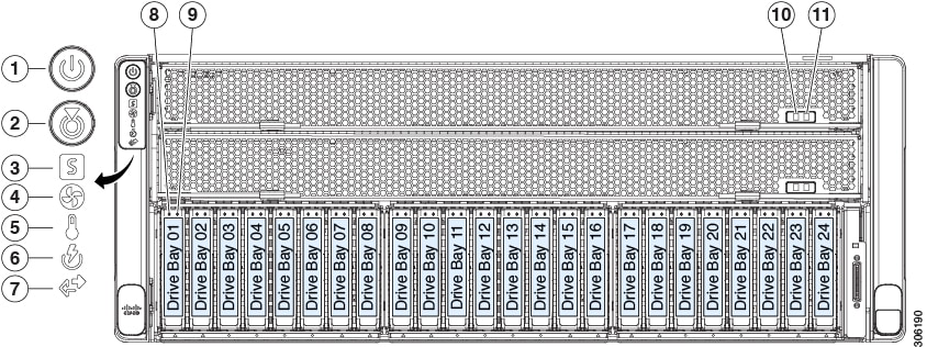
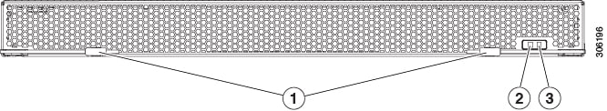
Front-Panel LEDs
|
LED Name |
States |
|||
|
1 |
Power button/LED |
|
||
|
2 |
Unit identification button/LED |
|
||
|
3 |
System status LED |
|
||
|
4 |
Fan status LED |
|
||
|
5 |
Temperature status LED |
|
||
|
6 |
Power supply status LED |
|
||
|
7 |
Network link activity LED |
|
||
|
8 SAS |
SAS/SATA drive fault LED
|
|
||
|
9 SAS |
SAS/SATA drive activity LED |
|
||
|
8 NVMe |
NVMe SSD drive fault LED
|
|
||
|
9 NVMe |
NVMe SSD activity LED |
|
||
|
10 |
CPU module power status LED |
|
||
|
11 |
CPU module fault LED |
|
||
|
- |
DVD drive activity LED (optional DVD module not shown) |
|
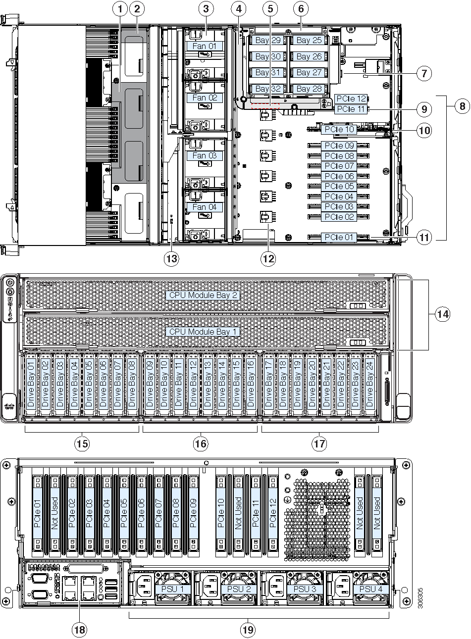
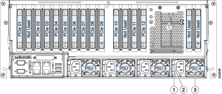
Rear-Panel LEDs

|
LED Name |
States |
|
|
1 |
1-Gb/10-Gb Ethernet link speed (on both LAN1 and LAN2) These ports auto-negotiate link speed based on the link-partner capability. |
|
|
2 |
1-Gb/10-Gb Ethernet link status (on both LAN1 and LAN2) |
|
|
3 |
1-Gb Ethernet dedicated management link speed |
|
|
4 |
1-Gb Ethernet dedicated management link status |
|
|
5 |
Rear unit identification |
|
|
6 |
Power supply status (one LED each power supply unit) |
AC power supplies:
|
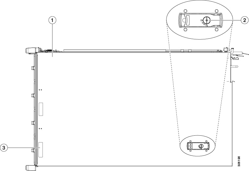
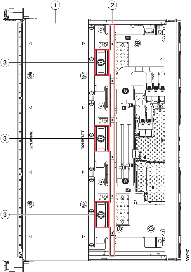
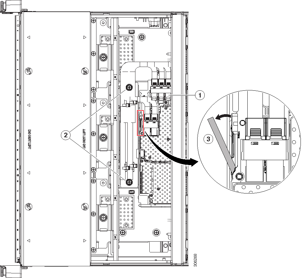
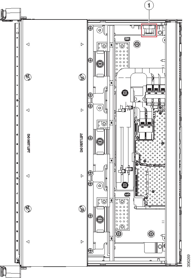
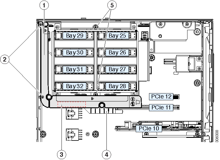
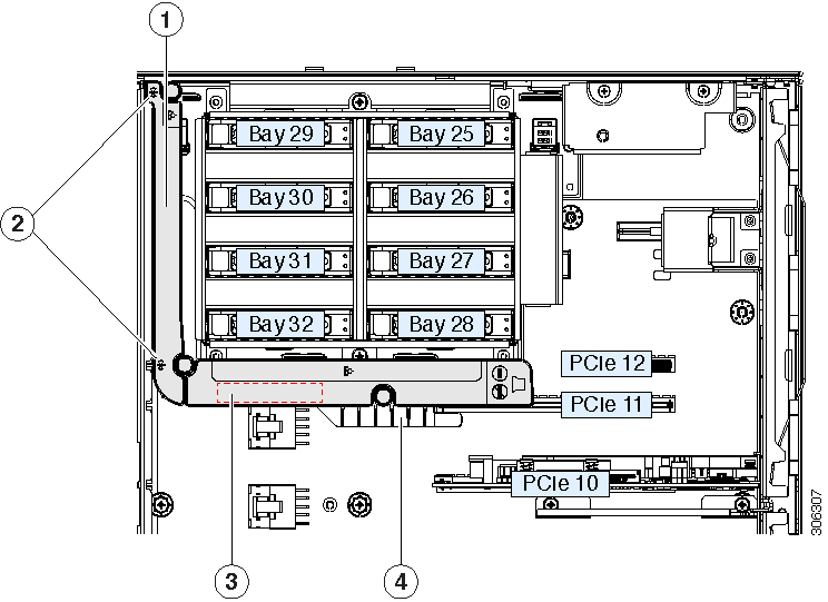
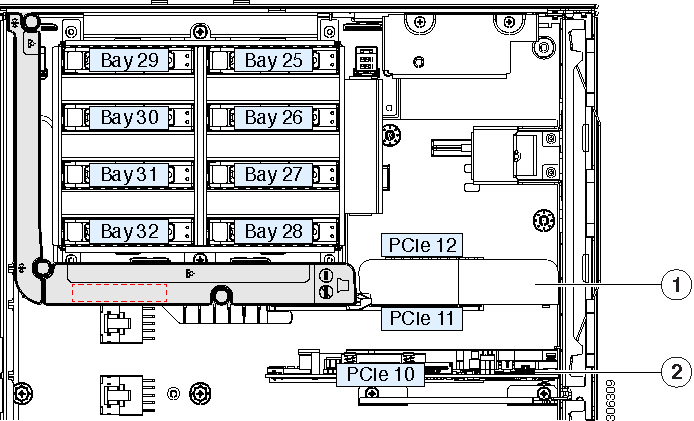
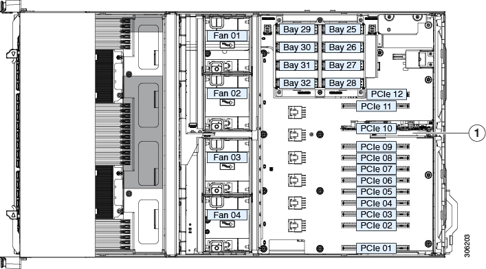
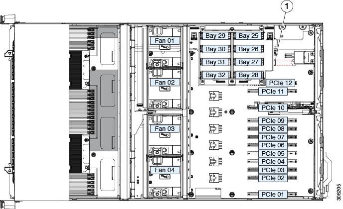
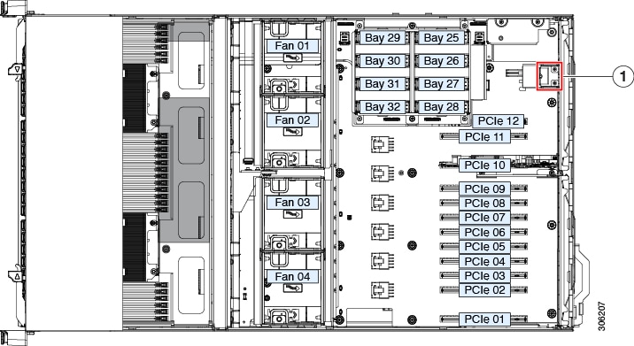
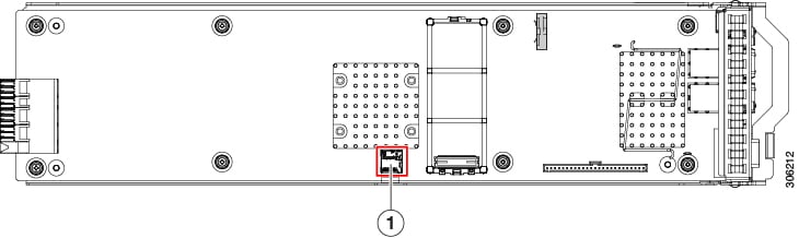
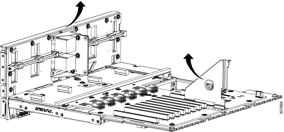
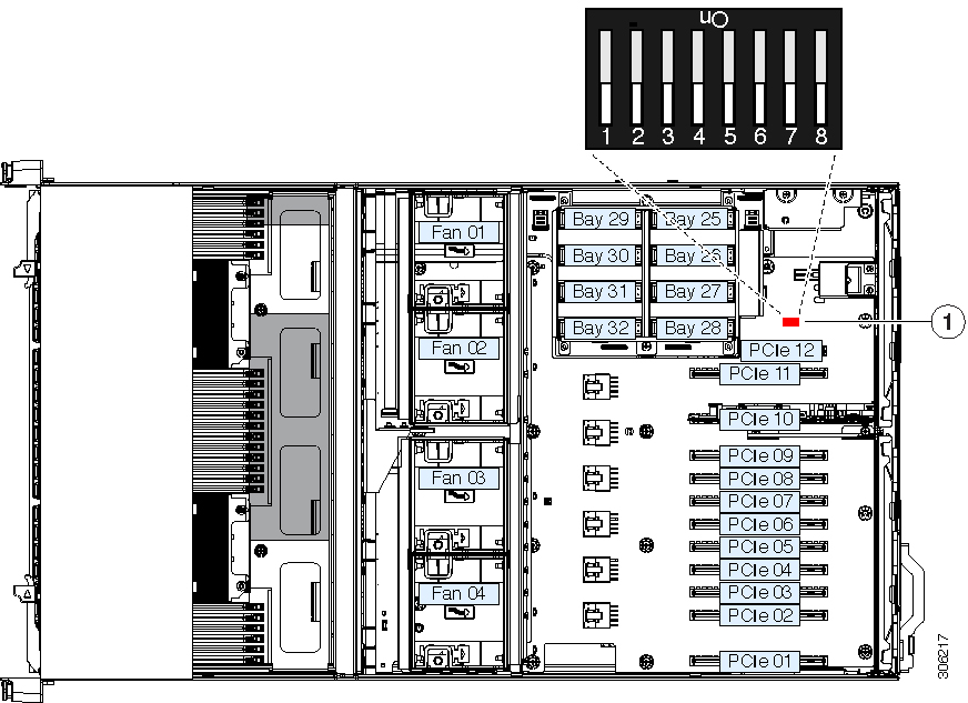
Internal Diagnostic LEDs
The system has the following internal fault LEDs to help with identifying a failing component:
-
Each chassis fan module has a fault LED on top of the module. These fan LEDs operate only when the system is in standby power mode.
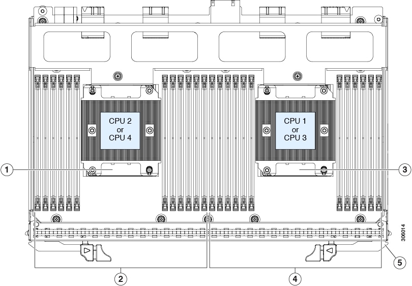
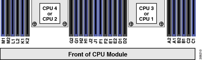
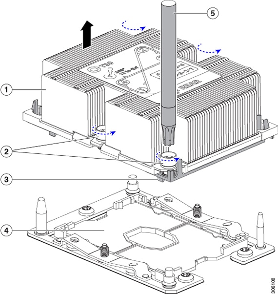
-
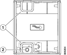
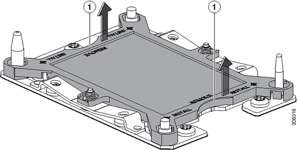
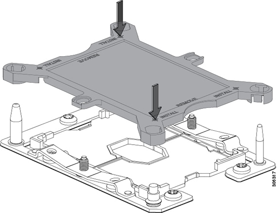
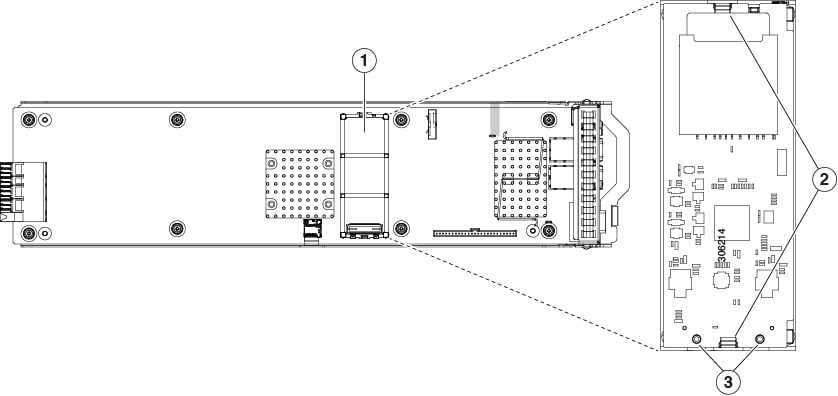
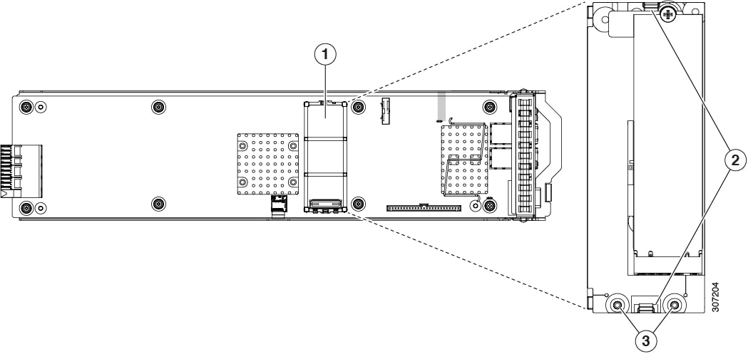
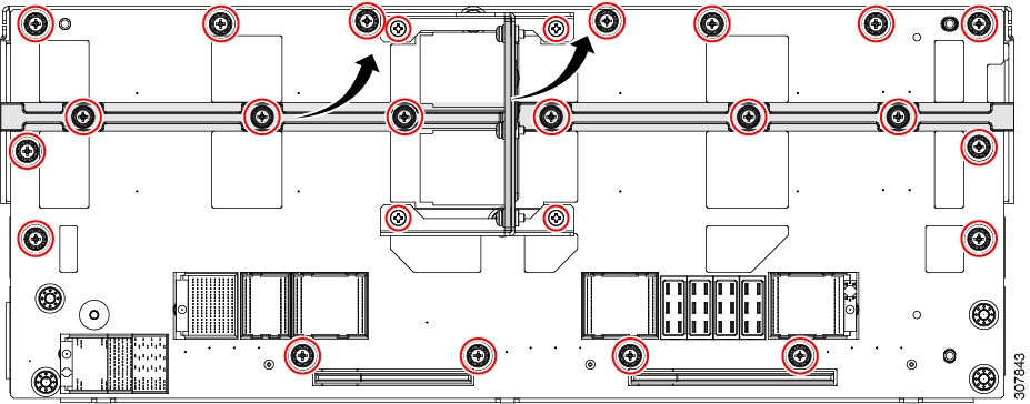
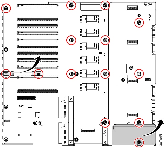
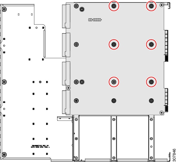
The CPU module has internal fault LEDs for CPUs and DIMMs on the CPU module board. POST and runtime error detection routines are stored in on-board registers. The contents of the registers are preserved for a limited time by a supercap voltage source.
To operate the LEDs, press switch SW1 on the board after the CPU module is removed from the chassis.

|
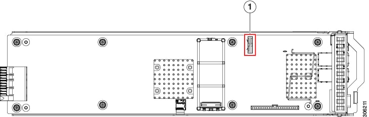
1 |
CPU fault LEDs (one behind each CPU socket on the board).
|
3 |
DIMM fault LEDs (one next to each DIMM socket on the board)
|
|
2 |
Switch SW1 SW1 is labeled, " PRESS HERE TO SEE FAULTS". |
- |


 Feedback