Cisco and Hitachi Adaptive Solutions for Converged Infrastructure as a Stretched Data Center
Available Languages

Cisco and Hitachi Adaptive Solutions for Converged Infrastructure as a Stretched Data Center
Design and Implementation Guide for Cisco and Hitachi Adaptive Solutions with Cisco ACI Multi-Pod and Hitachi Global-Active Device
Last Updated: December 20, 2019

About the Cisco Validated Design Program
The Cisco Validated Design (CVD) program consists of systems and solutions designed, tested, and documented to facilitate faster, more reliable, and more predictable customer deployments. For more information, go to:
http://www.cisco.com/go/designzone.
ALL DESIGNS, SPECIFICATIONS, STATEMENTS, INFORMATION, AND RECOMMENDATIONS (COLLECTIVELY, "DESIGNS") IN THIS MANUAL ARE PRESENTED "AS IS," WITH ALL FAULTS. CISCO AND ITS SUPPLIERS DISCLAIM ALL WARRANTIES, INCLUDING, WITHOUT LIMITATION, THE WARRANTY OF MERCHANTABILITY, FITNESS FOR A PARTICULAR PURPOSE AND NONINFRINGEMENT OR ARISING FROM A COURSE OF DEALING, USAGE, OR TRADE PRACTICE. IN NO EVENT SHALL CISCO OR ITS SUPPLIERS BE LIABLE FOR ANY INDIRECT, SPECIAL, CONSEQUENTIAL, OR INCIDENTAL DAMAGES, INCLUDING, WITHOUT LIMITATION, LOST PROFITS OR LOSS OR DAMAGE TO DATA ARISING OUT OF THE USE OR INABILITY TO USE THE DESIGNS, EVEN IF CISCO OR ITS SUPPLIERS HAVE BEEN ADVISED OF THE POSSIBILITY OF SUCH DAMAGES.
THE DESIGNS ARE SUBJECT TO CHANGE WITHOUT NOTICE. USERS ARE SOLELY RESPONSIBLE FOR THEIR APPLICATION OF THE DESIGNS. THE DESIGNS DO NOT CONSTITUTE THE TECHNICAL OR OTHER PROFESSIONAL ADVICE OF CISCO, ITS SUPPLIERS OR PARTNERS. USERS SHOULD CONSULT THEIR OWN TECHNICAL ADVISORS BEFORE IMPLEMENTING THE DESIGNS. RESULTS MAY VARY DEPENDING ON FACTORS NOT TESTED BY CISCO.
CCDE, CCENT, Cisco Eos, Cisco Lumin, Cisco Nexus, Cisco StadiumVision, Cisco TelePresence, Cisco WebEx, the Cisco logo, DCE, and Welcome to the Human Network are trademarks; Changing the Way We Work, Live, Play, and Learn and Cisco Store are service marks; and Access Registrar, Aironet, AsyncOS, Bringing the Meeting To You, Catalyst, CCDA, CCDP, CCIE, CCIP, CCNA, CCNP, CCSP, CCVP, Cisco, the Cisco Certified Internetwork Expert logo, Cisco IOS, Cisco Press, Cisco Systems, Cisco Systems Capital, the Cisco Systems logo, Cisco Unified Computing System (Cisco UCS), Cisco UCS B-Series Blade Servers, Cisco UCS C-Series Rack Servers, Cisco UCS S-Series Storage Servers, Cisco UCS Manager, Cisco UCS Management Software, Cisco Unified Fabric, Cisco Application Centric Infrastructure, Cisco Nexus 9000 Series, Cisco Nexus 7000 Series. Cisco Prime Data Center Network Manager, Cisco NX-OS Software, Cisco MDS Series, Cisco Unity, Collaboration Without Limitation, EtherFast, EtherSwitch, Event Center, Fast Step, Follow Me Browsing, FormShare, GigaDrive, HomeLink, Internet Quotient, IOS, iPhone, iQuick Study, LightStream, Linksys, MediaTone, MeetingPlace, MeetingPlace Chime Sound, MGX, Networkers, Networking Academy, Network Registrar, PCNow, PIX, PowerPanels, ProConnect, ScriptShare, SenderBase, SMARTnet, Spectrum Expert, StackWise, The Fastest Way to Increase Your Internet Quotient, TransPath, WebEx, and the WebEx logo are registered trademarks of Cisco Systems, Inc. and/or its affiliates in the United States and certain other countries.
All other trademarks mentioned in this document or website are the property of their respective owners. The use of the word partner does not imply a partnership relationship between Cisco and any other company. (0809R)
© 2019 Cisco Systems, Inc. All rights reserved.
Table of Contents
Cisco and Hitachi Adaptive Solutions for CI Overview
Cisco ACI Multi-Pod Design with ACI 4.2
Cisco Workload Optimization Manager
APIC Controller Considerations
Hitachi Global-Active Device (GAD)
Cisco UCS Domain Configuration
Deployment Hardware and Software
DC1 Physical Cabling for the Cisco UCS 6454 with the VSP 5100
DC2 Physical Cabling for the Cisco UCS 6454 with the VSP G370
Cisco ACI Multi-Pod Deployment
Deploy Inter-Pod Network (IPN)
Setup ACI Fabric for Multi-Pod
Setup Pod-2 Spine Switches, Leaf Switches, and APIC(s)
Physical Connectivity - Inter-Pod Network
Setup ACI Fabric for Multi-Pod – Using Configuration Wizard
Configure Inter-Pod Connectivity
Add Physical Pod – Second Pod or Site (Pod-2)
Configure DHCP Relay on IPN Devices
Configure OSPF Interface Profile for Spines in Pod-2
Setup Fabric Access Policies for Spine Switches in Pod-1
Deploy Spine and Leaf Switches in Pod-2
Configure NTP for Pod-2 using Out-of-Band Management
Update BGP Route Reflector Policy for Pod-2
Update Pod Profile to Apply Pod Policies
Setup Fabric Access Policies for Spine Switches in Pod-2
Verify Pod-2 Switches are Part of the ACI Fabric
Verify Pod-2 APIC is Part of the APIC Cluster
Add Pod-2 APIC as DHCP Relay Destination
Verify ACI Multi-Pod Fabric Setup
Verify OSPF Status on Spine Switches
Verify MP-BGP EVPN Status on Spine Switches
Verify COOP Status on Spine Switches
Deploy Shared Layer 3 Connectivity to Outside – Pod-2
Create VLAN Pool for External Routed Domain
Configure Domain Type for External Routed Domain
Create Attachable Access Entity Profile for External Routed Domain
Configure Interfaces to External Routed Domain
Configure Tenant Networking for Shared L3Out
Configure External Routed Networks under Tenant Common
Create Contracts for External Routed Networks from Tenant (common)
Provide Contracts for External Routed Networks from Tenant (common)
Configure External Gateways in the Outside Network
Physical VSP Connections at Data Centers 1, 2 and 3
Configure Fibre Channel Ports at DC1 for Local Boot LUNs and VMFS Storage
Configure Fibre Channel Ports at DC2 for Local Boot LUNs and VMFS Storage
Deploy Hitachi GAD with RAIDCOM
Create a GAD Pair with HORCM Files
Cisco Validated Designs (CVDs) are systems and solutions that are designed, tested, and documented to facilitate and accelerate customer deployments. CVDs incorporate a wide range of technologies, products and best-practices into a portfolio of solutions that address the business needs of our customers.
Cisco and Hitachi are working together to deliver a converged infrastructure solution that helps enterprise businesses meet the challenges of today and position themselves for the future. This CVD expands the previously released Cisco and Hitachi Adaptive Solutions with Cisco ACI CVD which is a Virtual Server Infrastructure (VSI) incorporating the Cisco Application Centric Infrastructure (ACI). This reimplementation creates a stretched data center utilizing the Cisco ACI Multi-Pod design for a seamless network between locations, Hitachi Global-Active Device (GAD) for active/active storage across these same locations and features the new Hitachi VSP 5100.
This document explains the design and implementation of the Cisco and Hitachi Adaptive Solutions for Converged Infrastructure as a Virtual Server Infrastructure (VSI) using Cisco ACI and Hitachi GAD to create a private cloud extended across multiple locations. The recommended solution architecture is built on the Cisco Unified Computing System (Cisco UCS) using the unified software release to support the Cisco UCS hardware platforms for the Cisco UCS B-Series Blade Server, Cisco UCS 6400 or 6300 Fabric Interconnects, Cisco Nexus 9000 Series switches, Cisco MDS 9000 Multilayer switches, and Hitachi Virtual Storage Platform (VSP) 5000 system along with other enterprise VSP systems.
Introduction
Modernizing your data center can be overwhelming, and it’s vital to select a trusted technology partner with proven expertise. With Cisco and Hitachi as partners, companies can build for the future by enhancing systems of record, supporting systems of innovation, and growing their business. Organizations need an agile solution, free from operational inefficiencies, to deliver continuous data availability, meet SLAs, and prioritize innovation.
Cisco and Hitachi Adaptive Solutions for Converged Infrastructure as a Stretched Data Center is a best practice data center architecture extended between locations as a seamless environment for the underlying network, storage hypervisor-based compute infrastructure. This architecture expands the Cisco and Hitachi Adaptive Solutions with Cisco ACI utilizing the Cisco ACI Multi-Pod design for a uniform network and incorporates Hitachi GAD for storage resiliency between locations and complies with the VMware vSphere Metro Storage Cluster (vMSC) specifications.
This design also features the introduction of the Hitachi VSP 5100 for both NVMe and SAS flash storage. The Hitachi VSP connects through the Cisco MDS Multilayer Switch to Cisco UCS and is enabled within the ACI network using the Cisco Nexus family of switches.
The reference architecture covers specifics of products utilized within the Cisco validation lab, but the solution is considered relevant for equivalent supported components listed within Cisco and Hitachi Vantara’s published compatibility matrixes. Supported adjustments from the example validated build must be evaluated with care as their implementation instructions may differ.
Audience
The audience for this document includes, but is not limited to; sales engineers, field consultants, professional services, IT managers, partner engineers, and customers who want to modernize their infrastructure to meet SLAs and their business needs at any scale.
Purpose of this Document
This document discusses the design and implementation of the Cisco and Hitachi Adaptive Solutions for Converged Infrastructure as a Stretched Data Center. This solution features a validated reference architecture composed of:
· Cisco UCS Compute
· Cisco Nexus Switches with ACI implementing the Cisco ACI Multi-Pod design
· Cisco MDS Multilayer Fabric Switches
· Hitachi Virtual Storage Platform
· Hitachi GAD
The design and technology decisions that went into this solution directly extend the previously published Cisco and Hitachi Adaptive Solutions for Converged Infrastructure with Cisco ACI Design Guide and the Cisco and Hitachi Adaptive Solutions for Converged Infrastructure with Cisco ACI Deployment Guide.
Solution Summary
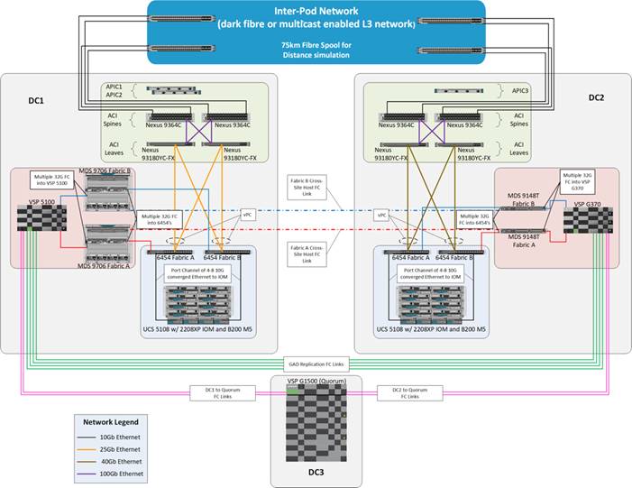
The Cisco and Hitachi Adaptive Solutions for CI as a Stretched Data Center is a validated reference architecture incorporating Cisco and Hitachi products to produce a resilient uniform data center infrastructure spanning multiple locations, keeping with the VMware restraints of the vMSC specification. In this validation, the IP network was displaced with a series of 75KM fibre spools and the SAN network was connected with shorter multimode fibre, relying on the independent validation of long-distance FC connections supported by both Cisco and Hitachi. The topology of this lab environment is shown in Figure 1.
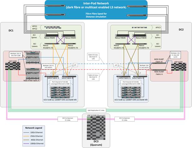
Table 1 lists the hardware deployed in this reference architecture.
Table 1 Reference Architecture Hardware
| DC1 |
DC2 |
| Hitachi VSP 5100 |
Hitachi VSP G370 |
| Cisco MDS 9706 Multilayer Director Switches |
Cisco MDS 9148T Multilayer Fabric Switches |
| Cisco UCS B200 M5 Blade Servers |
Cisco UCS B200 M5 Blade Servers |
| Cisco UCS 6454 Fabric Interconnects |
Cisco UCS 6454 Fabric Interconnects |
| Cisco ACI Application Policy Infrastructure Controllers |
Cisco ACI Application Policy Infrastructure Controller |
| Cisco Nexus 93180YC-FX Switches (Leaf) |
Cisco Nexus 93180YC-FX Switches (Leaf) |
| Cisco Nexus 9364C Switches (Spine) |
Cisco Nexus 9364C Switches (Spine) |
| Cisco Nexus 93180YC-EX Switches (NX-OS Standalone Mode Data Center Interconnect/ Existing Network connectivity as implemented for lab simulation) |
Cisco Nexus 93180YC-EX Switches (NX-OS Standalone Mode Data Center Interconnect/ Existing Network connectivity as implemented for lab simulation) |
Cisco and Hitachi Adaptive Solutions for CI Overview
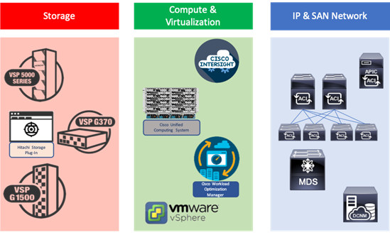
This Adaptive Solutions for CI release extends the previous Adaptive Solutions for CI with Cisco ACI CVD, adding new products from both Cisco and Hitachi to create the uniform stretched data center solution. Figure 2 illustrate the summary of the technologies used in this validated design. A full list of products and product references can be found in the Appendix: Solution References section.
Figure 2 Components in Adaptive Solutions for CI as a Stretched Data Center
What’s New in this Release?
Cisco ACI Multi-Pod Design with ACI 4.2
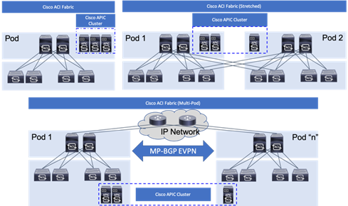
Cisco ACI is a holistic architecture that introduces hardware and software innovations built upon the Cisco Nexus 9000® Series product line. Cisco ACI provides a centralized policy-driven application deployment architecture that is managed through the Cisco Application Policy Infrastructure Controller (APIC). The Cisco ACI Multi-Pod design allows this architecture to extend the ACI Fabric in a uniform manner across multiple locations, defined as Pods, without the spine-leaf mesh requirements across pods implemented with the Stretched design of the ACI Fabric.
A thorough explanation of the ACI Multi-Pod design can be found in the ACI Multi-Pod White Paper.
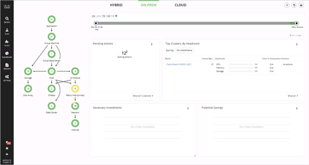
Cisco Workload Optimization Manager
The Cisco Workload Optimization Manager (CWOM) is software that continuously analyzes workload consumption, costs, and compliance constraints and automatically allocates resources in real-time, on-premises and in the cloud. As an optional component to the Adaptive Solutions infrastructure, it brings planning and efficiency to resource use and expansion needs. The CWOM can do the following:
· Deliver better application response time
· Increase utilization by 20% or more
· Reduce user generated tickets by 20% or more
· Show a ROI within 90 days or less
To learn more about CWOM, go to: https://www.cisco.com/c/en/us/products/servers-unified-computing/workload-optimization-manager/index.html.
Hitachi GAD Technology
GAD enables you to create and maintain synchronous, remote copies of data volumes. A Virtual Storage Machine (VSM) is configured in the primary and secondary storage systems using the actual information of the primary storage system, and the GAD primary and secondary volumes are assigned the same virtual LDEV (Logical Device) number in the VSM. This enables the host to see the pair volumes as a single volume on a single storage system, and both volumes receive the same data from the host. A quorum disk, which can be in a third and external storage system or in an iSCSI-attached host server, is used to monitor the GAD pair volumes. The quorum disk acts as a heartbeat for the GAD pair, with both storage systems accessing the quorum disk to check on each other. A communication failure between systems results in a series of checks with the quorum disk to identify the problem so the system can receive host updates.
Figure 3 Global Active Device between Primary and Secondary Data Centers
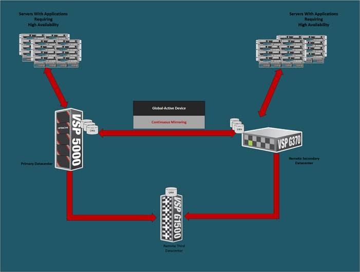
VMware Native Multi-Pathing (NMP) on the host runs in the Active/Active configuration. While this configuration works well at campus distances, at metro distances Asymmetric Logical Unit Access (ALUA) is required to support optimized/nonoptimized paths and ensure that the shortest path is used. If the host cannot access the primary volume (P-VOL) or secondary volume (S-VOL), host I/O is redirected by the alternate path software to the appropriate volume without any impact to the host applications.
Hitachi Virtual Storage Platform 5000 Series
The Hitachi Virtual Storage Platform 5000 series is comprised of the following:
· Hitachi VSP 5000 Series – The Foundation for a Modern Storage Infrastructure. A completely new, enterprise-class, flash array and the next evolution of the Hitachi VSP series. Its innovative, scale-out design is optimized for NVMe (non-volatile memory express) and SCM (Storage class memory).
· SVOS RF - Legendary Hitachi Resilience and Performance, Optimized for NVMe. A new version of SVOS RF (v.9.x) which has been optimized for the VSP 5000 series scale-out, NVMe design. It incorporates AI and ML to reduce cost with intelligent tiering that automates data placement to assure that your data always resides on the most optimized tier.
To ensure the best possible customer experiences, Hitachi Virtual Storage Platform (VSP) 5000 series reliably delivers more data faster than ever for open systems and mainframe applications. The enterprise-level VSP 5000 series starts as small as 3.8TB and grows to 69PB of raw capacity. With scalability to handle up to 21 million IOPS, multiple application workloads can be consolidated for cost savings. All models in the VSP 5000 series are backed by the industry’s most comprehensive 100 percent data availability guarantee to ensure that your operations are always up and running. Hitachi Remote Ops monitoring system and Hitachi Ops Center Analyzer enable industry-leading uptime.
Challenges to digital business initiatives include sprawling storage resources that operate in silos, slow response times that frustrate you, inadequate security and lengthy deployment processes for new IT services. VSP 5000 series was designed to meet these challenges head-on.
NVMe Done Right
The all-flash VSP 5000 series is the best choice for blazing flash performance with response times as low as 70 microseconds.
Cost-Saving Capacity Efficiency
Adaptive data reduction (ADR), provided by Hitachi Storage Virtualization Operating System RF (SVOS RF), enables organizations to improve storage utilization, reduce storage footprint and control costs. ADR offers selectable compression and deduplication for all media, which can be enabled at a volume level, making the system tunable. With guaranteed total efficiency rates of up to 7:1, you save on not only capacity purchases but also floor-space consumption, utility charges and support costs.
Optimize Operations with Artificial Intelligence
All VSP systems are packaged with Hitachi Ops Center Analytics. Our AI-powered solution constantly analyzes telemetry to optimize application performance and prevent extended outages. It works with Hitachi Ops Center Automator to maintain best practices and quality of service (QoS). Manual administrative tasks are streamlined and implemented with fewer errors, speeding addition of new applications and expansion of existing applications.
Simple, Easy-to-Use Management
The VSP family can be set up quickly and managed with ease using Hitachi Ops Center Administrator and its intuitive graphical user interface. RESTAPIs allow integration with existing toolsets and automation templates to further consolidate management tasks. Reduce complexity of steps needed to deploy, monitor and reconfigure storage resources to centralize administrative operations.
Protect Your Data from Unauthorized Access
The VSP 5000 models are hardened to prevent any leaks of physical data and unauthorized system access. Additional measures are available to ensure quick recovery from ransomware attacks.
Resiliency You Can Rely On
Leveraging hot-swappable components, nondisruptive upgrades and outstanding data protection, the VSP 5000 series offers complete system redundancy and is backed by our 100% data availability guarantee. Quadruple redundancy protects against failures even during routine maintenance.
Virtualized Storage Management and Monitoring
Consolidate existing silos and simplify IT by virtualizing all storage under a single pane. External storage systems benefit from the data services that the VSP 5000 series delivers, including data reduction, metro clustering and Automation.
Modernized Consumption Models
In addition to standard capital expenditure (capex) and leasing models, we offer pay-per-use utility pricing and cloud-based consumption services to reduce upfront acquisition costs and better align what you pay with what you use.
Enjoy Peace of Mind
Comprehensive business continuity can be assured with active-active clustering via GAD. Enabling robust business-continuity solutions across multiple data centers, GAD offers zero downtime: Performance stays high, even when data protection is running.
Requirements
Each site needs to be deployed following the steps detailed in the Deployment Guide for Cisco and Hitachi Adaptive Solutions for Converged Infrastructure with Cisco ACI.
· The Primary site (DC1 in our reference), will conform as closely to the Deployment Guide as is appropriate to the customer environment.
· The Multi-Pod configuration section below to configure the IPN and the Spines/Leaf Switches in the Secondary site (DC2 in our reference).
· When the ACI fabric is setup/extended to the second site, DC2 can be completed with some minor changes that will be noted in this document.
These sites need to be connected by fibre or a multicast enabled L3 network for IP traffic, supported long reach fibre channel connections, and conform to the following requirements:
· Less than 10ms RTT for communication for IP and fibre channel traffic.
· GAD compliant VSP devices at each location.
· A third independent location hosting a VSP resource to act as a mediator.
· Processor compatibility between Cisco UCS servers across the differing sites to be able to support vMotion across sites (optionally configure vSphere EVC if there is a disparity).
Physical Topology
The physical topology is based on the design detailed in the Adaptive Solutions for Converged Infrastructure with Cisco ACI Design Guide, as shown in Figure 4.
Figure 4 Adaptive Solutions for Converged Infrastructure with Cisco ACI
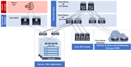
This data center architecture is powerful and resilient, and can be implemented in multiple locations but would be limited in base connectivity as to what might be available through a connecting WAN as shown in Figure 5.
Figure 5 Adaptive Solutions at Multiple Locations
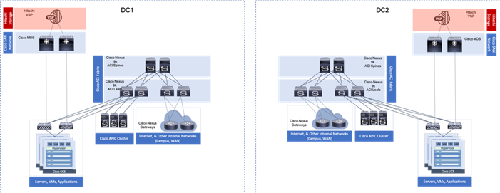
Provisioning in this manner may work for locations with greatly differing functions, and little need for collaboration. Industry trends toward collaboration speak of a much different need, with groups commonly dispersed across locations and a need to maintain functionality in the event of an entire location facing a disruption.
These needs for greater collaboration and resiliency across locations can be met by building a uniform experience between locations stretching the storage, network, and compute resources between data center resources as shown in Figure 6.
Figure 6 A Uniform Stretched Data Center
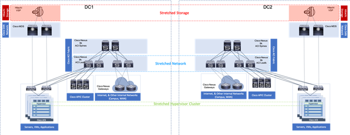
With the Adaptive Solutions Stretched Data Center architecture, the technologies of Hitachi GAD and Cisco ACI Multi-Pod are incorporated to expand the original architecture into a uniform and resilient infrastructure of stretched storage, network and compute, extended across potentially geographically displaced locations as shown in Figure 7.
Figure 7 Adaptive Solutions Stretched Data Center with Cisco Multi-Pod and Hitachi GAD
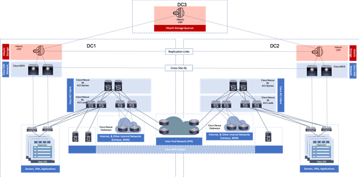
This reference architecture has been validated in Cisco labs with the assistance of Hitachi Vantara. Components and configurations shown should not always be considered to be prescriptive to the solution as the customer will have options for hardware and software not specified in this document. However, the interoperability guidelines from both companies should be referred to when departing from the validated design.
Network Design
The ACI design in this architecture leverages Multi-Pod by implementing an Inter-Pod Network (IPN) to enable traffic across the leaves and spines of separated pods without requiring a direct mesh topology. The IPN is not part of the ACI fabric, but it connects to each pod through one or more spine switches within each pod. The design specifics of the pods within each DC of the stretched architecture can be found in the previously mentioned Adaptive Solutions for Converged Infrastructure with Cisco ACI Design Guide.
ACI Multi-Pod Design
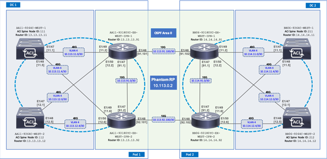
The ACI Multi-Pod design used in this CVD is shown in Figure 8.
Figure 8 Adaptive Solutions ACI Multi-Pod Design
IPN Configuration
The IPN consists of two Nexus switches in each data center connected using a 10Gbps 75 km long fiber. The dual link design provides high availability in case of a link failure. Each spine is connected to each of the Nexus using a 10Gbps connection for a fully redundant setup.
Each Nexus is configured for the following features to support the Multi-Pod network:
PIM Bidir Configuration
In addition to unicast communication, Layer 2 multi-destination flows belonging to bridge domains that are extended across Pods must also be supported. This type of traffic is usually referred to as Broadcast, Unknown Unicast and Multicast (BUM) traffic and it is exchanged by leveraging VXLAN data plane encapsulation between leaf nodes. Inside a Pod (or ACI fabric), BUM traffic is encapsulated into a VXLAN multicast frame and it is always transmitted to all the local leaf nodes. In order to flood the BUM traffic across Pods, the same multicast used inside the Pod is also extended through the IPN network. PIM bidir enables this functionality on the IPN devices.
OSPF Configuration
OSPF is enabled on Spine switches and IPN devices to exchange routing information between the Spine switches and IPN devices.
DHCP Relay Configuration
In order to support auto-provisioning of configuration for all the ACI devices across multiple Pods, the IPN devices connected to the spines must be able to relay DHCP requests generated from ACI devices in remote Pods toward the APIC node(s) active in the first Pod.
Interface VLAN Encapsulation
The IPN device interfaces connecting to the ACI Spines are configured as sun-interfaces with VLAN encapsulation value set to 4.
MTU Configuration
The IPN devices are configured for maximum supported MTU value of 9216 to handle the VxLAN overhead.
TEP Pools and Interfaces
In Cisco ACI Multi-Pod setup, unique Tunnel Endpoint (TEP) Pools are defined on each site. In this CVD, these pools are 10.11.0.0/16 and 10.12.0.0/16 for the two data centers.
External TEP
The pod connection profile uses a VXLAN TEP (VTEP) address called the External TEP (ETEP) as the anycast shared address across all spine switches in a pod. This IP address should not be part of the TEP pool assigned to each pod and is therefore selected outside the two networks listed above. The IP addresses used in the two data centers are 10.241.249.1 and 10.242.249.1.
APIC Controller Considerations
The ACI Multi-Pod fabric brings interesting considerations for the deployment of the APIC controller cluster managing the solution. To increase the scalability and resiliency of the design, APIC supports data sharding for data stored in the APIC. The basic idea behind sharding is that the data repository is split into several database units, known as ‘shards’ and the shard is then replicated three times, with each copy assigned to a specific APIC appliance. In a three node APIC cluster, one replica of each shard exists on every node. In this scenario, if two of the three nodes become unavailable, the shards in third node become read-only because of lack of quorum and stay in read-only mode until the other nodes become accessible again.
Figure 9 APIC Nodes and Data Sharding
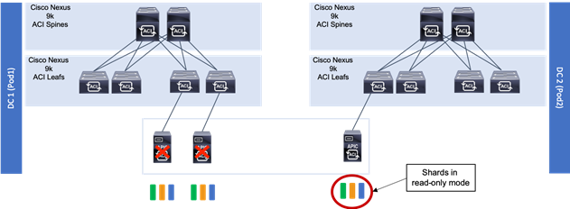
In Figure 9, the three APIC nodes are distributed across the two data centers. In case of a split-brain scenario where two data centers cannot communicate to each other over the IPN, this implies that the shards on the APIC nodes in Pod1 would remain in full ‘read-write’ mode, allowing a user connected there to make configuration changes however the shards in Pod2 will move to a ‘read-only’ mode. Once the connectivity issues are resolved and the two Pods regain full connectivity, the APIC cluster would come back together and any change made to the shards in majority mode would be applied also to the rejoining APIC nodes.
To mitigate this scenario, customers can deploy a 3 nodes APIC cluster with two nodes in Pod1 and one node in Pod2 and then add a fourth backup APIC node in Pod2 to handle the full site failure scenario. The backup APIC server however should only be brought into action if a long-term connectivity outage or data center maintenance is expected. For typical short-term outages, three node cluster should suffice in most scenarios.
For more information about APIC cluster and sizing recommendations, consult the Multi-Pod design white paper: https://www.cisco.com/c/en/us/solutions/collateral/data-center-virtualization/application-centric-infrastructure/white-paper-c11-737855.html
Management Network Considerations
The management networks used for virtualization between the two sites will be configured in what can be summarized as either a Brown Field scenario (integrating with existing infrastructure), or Green Field scenario (new placement originating from the ACI fabric).
Figure 10 Brown Field Management Source External to the ACI Fabric
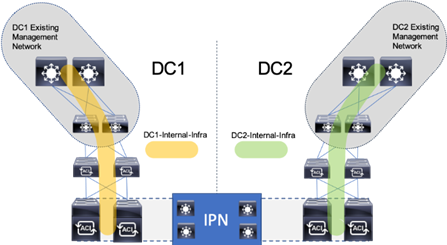
The Brown Field situation was configured in the previous single DC ACI design. The management network, referred to as an In Band Management (DC[1,2]-IB within ESX/UCS and DC[1,2]-Internal-Infra within ACI) in the CVD, came in from an external switch and routing for that network was managed by a router upstream of that switch. Continuation of a Brown Field model can occur as shown in Figure 10, but some routing will need to be worked out external to the fabric if this implementation persists as traffic will need to traverse cross site.
Figure 11 Green Field Management from the ACI Fabric
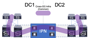
A single unified Cross Data Center Management EPG illustrated in Figure 12 (referenced as Common in the deployment), provides the default connectivity needed for vCenter and other management VMs to exist within either site. As an option, site specific management that is configured within, or ported into the ACI fabric can valid. If site specific management is created or ported into the ACI fabric, it will need have one of the management EPGs extended as was mentioned previously.
These options are not prescriptive and should be selected as appropriate to the deployed environment. In the validated architecture, a mixture of these two scenarios was implemented as shown in Figure 12.
Figure 12 Cross DC Mgmt along with DC Specific Management
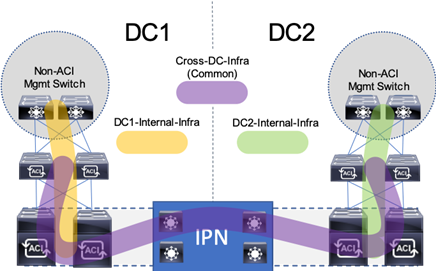
The above configuration sets up DC specific EPGs for physical and virtual infrastructure that wouldn’t be appropriate to exist outside of the specific DC, while maintaining the L3 gateway for these EPGs to set the availability to these resources through contracts and filters specified by the ACI fabric.
The Cross DC management network and the DC Internal Infra appropriate to the DC will be extended into the respective UCS domain for the location, and the hypervisors hosted within the UCS domain.
Storage Design
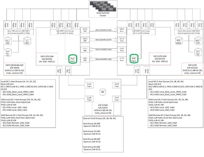
The solution explained in this CVD presents a VMware Metro Storage Cluster (vMSC) – compatible two-site stretched cluster utilizing Hitachi VSP storage, Cisco compute, and Cisco MDS Multilayer Fabric Switches. This architecture will allow synchronous active-active remote copies between your primary VSP G5100 at DC1 and VSP G370 at DC2. VSP G1500 is used as the 3rd quorum system at data center 3 to verify data consistency between data centers in respect to data in flight. GAD and vMSC allows storage high availability across both sites for enhanced protection of mission critical VM’s and applications running on the cluster. With this design, in the event of a path, replication link, primary system, secondary system, or wide area network (WAN) failure, the data being replicated with GAD will stay online and consistent, preventing down time. Utilizing VMware vSphere vCenter 6.7 U2 native multipathing (NMP), ALUA settings are honored from the Hitachi VSP’s for seamless failover to remove/standby hosts in the event of an outage. Figure 13 illustrates a fully built-out environment with Cisco VSI infrastructure utilizing Hitachi VSP 5000 with GAD technology.
Figure 13 Storage Configuration Between Systems Performing GAD Replication
Hitachi Global-Active Device (GAD)
As part of Hitachi SVOS, VSM technology ensures two physical systems are logically presented as one system. GAD feature implements cross-mirrored storage volumes between two Virtual Storage Platform systems accepting read/write I/Os on both sides that are continuously updated. If a disk controller failure occurs at one site, the controller at the other site automatically takes over and accepts read/write I/Os. It enables production workloads on both systems, while maintaining full data consistency and protection. The GAD feature assures that an active and up to date storage volume is available to a production application despite the loss of a virtualized controller, system or site.
During an outage, GAD by design will block I/O to the respective site where the failure occurred by pushing status PSUE (Pair Split under Error) to the volume and redirects all I/O to the alternate site automatically by honoring ALUA settings with the use of NPM.
For more information about GAD, go to:
https://knowledge.hitachivantara.com/Documents/Management_Software/SVOS/9.1.x/Global-Active_Device
During an outage where pairs are suspended to either a PSUE or PSUS (Pair Split under Suspend) state, you must correct the cause of the outage and resync the active-active volume set so the same data is consistent at the primary site as well as the secondary site. For information on disaster recovery of GAD go to:
Optionally, you have the choice between using data center specific storage or highly available GAD datasets, within this deployment you will be able to use other Hitachi management products to allocate a VMFS datastore to your virtual environment.
VMware vSphere Metro Storage Cluster (vMSC)
A vMSC environment on Hitachi Virtual Storage Platform G and F series storage systems provides an ideal solution for maximizing availability and uptime. It clusters physical data centers within metro distances. This Metro Storage Cluster solution from Hitachi Vantara consists of storage systems presenting replicated storage as a single LUN from different geographically distributed sites. This design enables high availability of services by allowing virtual machine migration between sites with no downtime. A combination of software and hardware products from Hitachi Vantara provides the following key functions to a vSphere infrastructure:
· Host multipathing
· Internal and externalized storage provisioning
· Synchronous storage replication across metro cluster distances
· Transparent storage failover
· Host access via uniform (recommended) or non-uniform topology
These functions work together with VMware vSphere vMotion, VMware vSphere High Availability, and VMware vSphere Distributed Resource Scheduler to build this reference architecture for vMSC. The advanced functions found in Hitachi Virtual Storage Platform G and F series storage systems do the following:
· Fulfill the requirements of a virtual infrastructure
· Lessen the need for additional hardware that may be required in traditional Metro Storage Cluster solutions
vMSC supports Stretched Storage, leveraging GAD which provides a single stretched datastore across the data center. Within this design VM Component Protection (VMCP) is used to protect virtual machines from storage related events, such as Permanent Device Loss (PDL) and All Paths Down (APD). This paper shows the pre-designed, pre-configured, and pre-validated solution as a reference architecture that is comprised of both a VMware vSphere stack and Stretched Storage stack, leveraging vMSC and GAD on Cisco UCS VSI infrastructure.
VMware Support
Hitachi VSP F series and G series are aligned with the VMware software-defined storage vision, providing the following support:
· vMSC: Using Hitachi GAD, you can create and maintain synchronous, remote copies of data volumes. A VSM is configured in the primary and secondary storage systems using the actual information of the primary storage system, and the GAD primary and secondary volumes are assigned the same virtual LDEV number in the VSM. This enables the host to see the pair volumes as a single volume on a single storage system, and both volumes receive the same data from the host. Configuring GAD as the backend storage for a vMSC provides an ideal solution for maximizing availability and uptime by clustering physical data centers that reside within metro distances of each other.
· Hitachi Storage Provider for VMware vCenter: Hitachi Storage Provider works with VMware vSphere API for Storage Awareness (VASA) to provide access to Hitachi VSP F series and G series. Storage Provider enables policy-based storage management using VMware Storage Policy-based Management (SPBM) and VMware Virtual Volumes (VVols). Storage Provider provides a simplified method for VMware admins and storage admins to deliver effective storage that meets advanced VM requirements.
· vSphere Storage APIs - Array Integration (VAAI): VAAI enables multiple storage functions (primitives) within vSphere to be offloaded to certified storage hardware. This reduces ESXi processor utilization by allowing certified storage hardware to perform these functions on the storage systems themselves. In many cases, VAAI accelerates these functions allowing them to complete in less time as compared to performing the functions within software on the ESXi host.
· Hitachi Storage Replication Adapter (SRA): Hitachi Storage Replication Adapter (SRA) for VMware Site Recovery Manager provides a disaster recovery (DR) solution that works with both your storage environment and your VMware environment. Arrays at both sites are "paired" during Site Recovery Manager configuration, and VMware administrators use the Site Recovery Manager application to manage the configuration and definition of the DR plan.
· vStorage API for Multipathing (VAMP): Hitachi VSP F series and G series support VAMP to provide enhanced control of I/O path selection and failover.
· vStorage API for Data Protection (VADP): Hitachi VSP F series and G series support VADP to enable backup applications to perform file-level or VM-level backup of running virtual machines.
Multipathing
VMware Native Multi-Pathing (NMP) is the multipathing software that integrates with GAD to provide load balancing, path optimization, path failover, and path failback capabilities for vSphere hosts. NMP will load-balance I/O between all available preferred paths (Active) from P-VOL and keep all paths to S-VOL as active non-optimized paths. NMP rules for the Hitachi VSP are now enabled by default within vSphere, this allows for reduction in time to production when deploying new vSphere ESXi clusters connected to Hitachi Storage. The rules will handle devices configured with ALUA to be used for GAD. In this guide, VMware’s Native Multi-Pathing is used.
Virtual Storage Machine (VSM)
The VSM is the unit that is used to manage virtualized storage system resources. You create a VSM within a physical storage system to enable the host server to recognize two storage systems as one virtual storage system.
When GAD is used to provide nondisruptive host access to volumes that reside on different storage systems, a VSM for the storage system that contains the primary volumes (P-VOLs) of the GAD pairs is created in the secondary storage system. For GAD, the primary storage system is the virtualized storage system.
Figure 14 illustrates the relationship between a (physical) storage system and VSM’s.
Figure 14 VSM Emulation Between Systems Performing GAD Replication
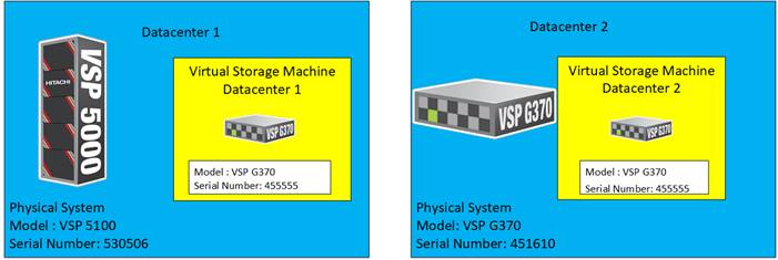
In this design, a common VSM model of VSP G370 was emulated. To learn more about VSM emulation types, go to:
Quorum
A quorum entity that is external to either system is normally in a separate location is used to determine the operational control when certain failure occurs to avoid split-brain scenarios. In a vMSC using VSP platform, there are various options for providing quorum services including a separate Storage system (including any supported 3rd party storage that can be attached to VSP G/F platform) or presenting an iSCSI disk from physical/virtual machine from 3rd site or cloud. In the case of this design guide, it is recommended to keep the quorum system at a third site. This is utilized in disaster situations where the primary or secondary data center is offline and the quorum is used to maintain data consistency between VSPs in GAD replication, and to verify fail over.
Example: External storage system: A 20GB LUN is created on an external storage array such as VSP G1500 or other supported external 3rd party storage array for use as a quorum disk. This LUN is presented to the Site 1 VSP and Site 2 VSP as externalized storage by virtue of VSP G/F platform SVOS virtualization device capability. The quorum disk stores continually updated information about data consistency in Hitachi GAD P-VOLs and S-VOLs for use during site failover operations. GAD uses the information in the event of a failure, to direct host operations to the other volume within the pair.
Quorum Links
In this design, two External Paths are configured between DC1 VSP 5100 storage and VSP G1500 quorum storage, and two more External paths between site 2 VSP G370 storage and VSP G1500 quorum storage.
Replication Links Main Control Unit and Remote Control Unit (MCU/RCU)
A storage replication link consists of bidirectional ports on the DC1 storage system connected to a remote-control unit bidirectional port that is defined on the DC2 storage system. It represents a bidirectional remote copy connection from the primary data volume (P-VOL) on the DC1 storage system to the secondary data volume (S-VOL) on the DC2 storage system. Within this design 2 sets of MCU/RCU paths are defined for storage replication.
Cisco MDS
The SAN of the Adaptive Solutions Stretched Data Center uses pairs of MDS switches at each location. These switches operate as parallel networks within each location and are connected across the data centers to their location counterparts with Inter-switch Links (ISL) as shown in Figure 15.
Figure 15 Adaptive Solutions SAN Connecting the Two Data Centers
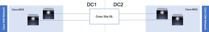
Symmetry is not required between the differing MDS pairs across the two locations, with DC1 using a pair of director class MDS 9700 series switches, and DC2 utilizing a pair of 9148Ts. Also, these switches across the extended SAN can be easily managed for both Zones and Devices Aliases through an optional DCNM implementation supporting both sites.
The zoning utilized within the MDS will enable access to boot LUNs, GAD VMFS datastores, as well as non-GAD VMFS datastores. The GAD resources from the opposing DC will be presented within the zoning to enable VMFS continuity in the event of an availability incident in the DC that is somehow specific to the VSP.
Figure 16 MDS A zoning for an example DC1 host
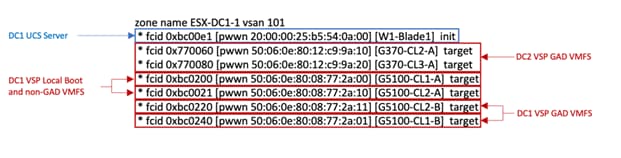
Created zonesets are shared across the DCs through the ISL connected SAN fabrics. Zones created for a host initiator in one DC will have its zone present across the ISL in the opposing DC to expose the VSP GAD targets from both sides.
Compute Design
Cisco UCS Domain Configuration
The Cisco UCS compute for both environments were configured in an identical manner, relying on the respective DC internal infra networks for the Cisco UCS FI management interfaces.
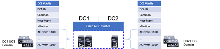
The ACI-vmm-[#] networks are configured to each UCS domain as needed through the ACI UCSM Integration. Both UCS domains are set as Switch Managers for the ACI Virtual Machine Manager (VMM) configured for the vCenter spanning both data centers. When an EPG is associated to the VMM, the VLAN allocated to it within the VMM is configured on the Cisco UCS FI uplinks, and appropriate vNIC templates associated with the hypervisor uplinks connected to the VMM managed vDS.
Consistency of the UCS Service Profiles between the two UCS domains was handled manually during the deployment, but could have been more efficiently synchronized by utilizing Cisco UCS Central (not explained in this validation) to create Global Service Profiles.
Cisco Management Components
Additional benefits are brought to the solution with the optional inclusion of CWOM and Cisco Intersight.
· Registering the Cisco UCS Fabric Interconnects and the vCenter to CWOM gives scaling visibility to components, tracking resources that are constrained or under used within the infrastructure.
· Registering the UCS Fabric Interconnect to Intersight gives extensive visibility into the UCS domain health, firmware revision compliance, and expedited support with Cisco TAC.
Virtualization Design
The virtualization design includes topics already mentioned in the previous storage and compute design sections, with additional specifics explained in the published Adaptive Solutions for Converged Infrastructure with Cisco ACI Design Guide.
Figure 17 vSphere Cluster in the Adaptive Solutions Stretched Data Center
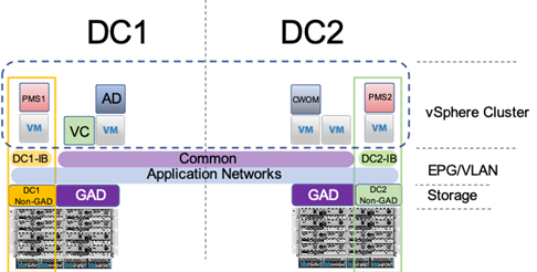
The deployment example shown in Figure 17 is shown with a single vSphere DRS cluster spanning both data center locations. Within this cluster there are three categories of VMs:
· VMs that should stay in DC1
· VMs that should stay in DC2
· VMs that can reside in either DC
VMs that will be specific to a DC are deployed to the Non-GAD storage associated with that DC, while all cross DC VMs will be deployed to GAD storage. The network port-groups will similarly need to be mapped to VMs appropriate for either mobility between locations, or an affinity to a specific DC. With these factors accounted for, VM Groups and Host Group pairings are created to lock VMs to the ESXi hosts of a particular DC if they should not traverse between DC locations either through DRS or an HA event.
Both the vCenter instance and the Active Director server participated in this cluster during the validation, residing on GAD storage and associated with the Common network to be available in either DC during the event of a site down scenario during testing. vSphere HA rules are negotiated by the hypervisor hosts during an event, so the availability of vCenter is not required for VM powerups to occur. This example is not intended to be a requirement of the deployment, but exists as an example of the resiliency that the solution can provide.
Architecture
Cisco and Hitachi Adaptive Solutions for Converged Infrastructure is a validated reference architecture targeting Virtual Server Infrastructure (VSI) implementations. The architecture was originally built for a single data center around the Cisco Unified Computing System (Cisco UCS) and the Hitachi Virtual Storage Platform (VSP) connected together by Cisco MDS Multilayer SAN Switches, and with the Cisco Application Centric Infrastructure using Cisco Nexus Switches. This single data center design is stretched across two potentially geographically displaced locations using the technologies of the Cisco Multi-Pod Design and Hitachi GAD, which will both be explained in these deployment instructions.
Deployment
The Adaptive Solutions Stretched Data Center utilizes the deployment guide of the published Adaptive Solutions for Converged Infrastructure with ACI for each of the DC placements shown in the architecture.
Cisco and Hitachi Adaptive Solutions for Converged Infrastructure with Cisco ACI Deployment Guide
You must complete the first DC setup using the steps and specifications found in the deployment guide and it’s required before beginning the Multi-Pod Deployment. This deployment guide will be referred to going forward as the DC1 Deployment Guide,
These deployments will differ slightly from the DC1 Deployment Guide, and components changed will be noted as follows:
Table 2 Validated Hardware and Software
| Component |
DC Location |
Software Version/Firmware Version |
|
| Network |
Cisco Nexus 93180YC-FX (leaf) |
Both |
14.2(1j) [14.1(2g) in initial release] |
| Cisco Nexus 9364C (spine) |
Both |
14.2(1j) [14.1(2g) in initial release] |
|
| Cisco APIC M2 |
Both |
4.2(1j) [4.1(2g) in initial release] |
|
| Cisco ExternalSwitch |
Shared |
1.1 [1.0 in initial release] |
|
| Compute |
Cisco UCS Fabric Interconnect 6454 |
Both |
4.0(4d) [4.0(4b) in initial release] |
| Cisco UCS 2208XP IOM |
Both |
4.0(4d) [4.0(4b) in initial release] |
|
| Cisco UCS B200 M5 |
Both |
4.0(4d) [4.0(4b) in initial release] |
|
| VMware vSphere |
Both |
6.7 U2 VMware_ESXi_6.7.0_13006603_Custom_Cisco_6.7.2.1.iso |
|
| ESXi 6.7 U2 nenic |
Both |
1.0.29.0 |
|
| ESXi 6.7 U2 nfnic |
Both |
4.0.0.40 [4.0.0.38 in initial release] |
|
| VMware vCenter Server Appliance |
Shared |
6.7 U2 |
|
| VM Virtual Hardware Version |
Both |
13 |
|
| Storage |
Hitachi VSP 5100 |
DC1 |
90-01-61 (SVOS 9.1.3) |
| Hitachi VSP G370 |
DC2 |
88-03-23 (SVOS 8.3.1) |
|
| Hitachi Storage Plugin for vCenter |
Shared |
4.1.0 [3.10.0 in initial release] |
|
| Hitachi Command Control Interface (CCI) |
|
01-52-03/01 |
|
| Cisco MDS 9706 |
DC1 |
8.3(2) [8.3(1) in initial release] |
|
| Cisco MDS 9148T |
DC2 |
8.3(2) |
|
| Cisco DCNM |
DC1 |
11.2(1) |
|
The VLANs used in each environment will be nearly identical, with the exception of the insertion of a DC2 specific VLAN for infrastructure placed in DC2 as opposed to DC1.
Table 3 VLANs used in the Deployment
| VLAN Name |
VLAN Purpose |
ID Used in Validating this Document |
Note |
| DC1-IB |
DC1 VLAN for Internal Infrastructure (UCSM/VSP) |
119 |
Referred to as Internal-Infra in the initial release, but will be utilized for physical and virtual infrastructure specific to DC1 |
| DC2-IB |
DC2 VLAN for Internal Infrastructure (UCSM/VSP) |
219 |
|
| Common |
VLAN for Shared Infrastructure (AD/DNS) |
319 |
|
| Host-Mgmt |
VLAN for Hypervisor Hosts (ESXi) |
419 |
|
| vMotion |
VLAN for vSphere vMotion traffic |
519 |
|
| Native |
VLAN to which untagged frames are assigned |
2 |
|
| App-vDS-[1-100] |
VLAN for Application VM Interfaces residing in vDS based port groups |
1100-1199 |
|
DC1 Physical Cabling for the Cisco UCS 6454 with the VSP 5100
Figure 18 Cabling Configuration used in the DC1 Design Featuring the Cisco UCS 6454 and the VSP 5100
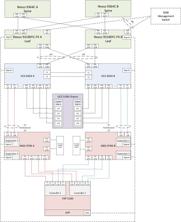
Table 4 Cisco Nexus 93180YC-FX A Cabling Information for DC1
| Local Device |
Local Port |
Connection |
Remote Device |
Remote Port |
| Cisco Nexus 93180YC-FX A |
Eth1/1 |
GbE |
GbE |
Any |
| Eth1/47 |
25GbE |
Cisco UCS 6454 FI A |
Eth 1/47 |
|
| Eth1/48 |
25GbE |
Cisco UCS 6454 FI B |
Eth 1/47 |
|
| Eth1/53 |
40GbE or 100GbE |
Cisco 9364C A (Spine) |
Eth 1/41 |
|
| Eth1/54 |
40GbE or 100GbE |
Cisco 9364C B (Spine) |
Eth 1/41 |
|
| MGMT0 |
GbE |
GbE management switch |
Any |
Table 5 Cisco Nexus 93180YC-FX B Cabling Information for DC1
| Local Device |
Local Port |
Connection |
Remote Device |
Remote Port |
| Cisco Nexus 93180YC-FX B |
Eth1/1 |
GbE |
GbE |
Any |
| Eth1/47 |
25GbE |
Cisco UCS 6454 FI A |
Eth 1/48 |
|
| Eth1/48 |
25GbE |
Cisco UCS 6454 FI B |
Eth 1/48 |
|
| Eth1/53 |
40GbE or 100GbE |
Cisco 9364C A (Spine) |
Eth 1/42 |
|
| Eth1/54 |
40GbE or 100GbE |
Cisco 9364C B (Spine) |
Eth 1/42 |
|
| MGMT0 |
GbE |
GbE management switch |
Any |
Table 6 Cisco UCS 6454 FI A Cabling Information for DC1
| Local Device |
Local Port |
Connection |
Remote Device |
Remote Port |
| Cisco UCS 6454 FI A |
FC 1/1 |
32Gb FC |
MDS 9706 A |
FC1/5 |
| FC 1/2 |
32Gb FC |
MDS 9706 A |
FC1/6 |
|
| Eth1/9 |
10GbE |
Cisco UCS Chassis 2208XP FEX A |
IOM 1/1 |
|
| Eth1/10 |
10GbE |
Cisco UCS Chassis 2208XP FEX A |
IOM 1/2 |
|
| Eth1/11 |
10GbE |
Cisco UCS Chassis 2208XP FEX A |
IOM 1/3 |
|
| Eth1/12 |
10GbE |
Cisco UCS Chassis 2208XP FEX A |
IOM 1/4 |
|
| Eth1/47 |
25GbE |
Cisco Nexus 93180YC-FX A |
Eth1/47 |
|
| Eth1/48 |
25GbE |
Cisco Nexus 93180YC-FX B |
Eth1/47 |
|
| L1 |
GbE |
Cisco UCS 6454 FI B |
L1 |
|
| L2 |
GbE |
Cisco UCS 6454 FI B |
L2 |
|
| MGMT0 |
GbE |
GbE management switch |
Any |
Table 7 Cisco UCS 6454 FI B Cabling Information for DC1
| Local Device |
Local Port |
Connection |
Remote Device |
Remote Port |
| Cisco UCS 6454 FI B |
FC 1/1 |
32Gb FC |
MDS 9706 A |
FC1/5 |
| FC 1/2 |
32Gb FC |
MDS 9706 A |
FC1/6 |
|
| Eth1/9 |
10GbE |
Cisco UCS Chassis 2208XP FEX B |
IOM 1/1 |
|
| Eth1/10 |
10GbE |
Cisco UCS Chassis 2208XP FEX B |
IOM 1/2 |
|
| Eth1/11 |
10GbE |
Cisco UCS Chassis 2208XP FEX B |
IOM 1/3 |
|
| Eth1/12 |
10GbE |
Cisco UCS Chassis 2208XP FEX B |
IOM 1/4 |
|
| Eth1/47 |
25GbE |
Cisco Nexus 93180YC-FX A |
Eth1/48 |
|
| Eth1/48 |
25GbE |
Cisco Nexus 93180YC-FX B |
Eth1/48 |
|
| L1 |
GbE |
Cisco UCS 6454 FI B |
L1 |
|
| L2 |
GbE |
Cisco UCS 6454 FI B |
L2 |
|
| MGMT0 |
GbE |
GbE management switch |
Any |
Table 8 Cisco MDS 9706 A Cabling Information for DC1
| Local Device |
Local Port |
Connection |
Remote Device |
Remote Port |
| Cisco MDS 9706 A |
FC 1/5 |
32Gb FC |
Cisco UCS 6454 FI A |
FC1/1 |
| FC 1/6 |
32Gb FC |
Cisco UCS 6454 FI A |
FC1/2 |
|
| FC 1/11 |
32Gb FC |
VSP 5100 Controller 1 |
CL1-A |
|
| FC 1/12 |
32Gb FC |
VSP 5100 Controller 2 |
CL2-A |
|
| FC 1/13 |
32Gb FC |
VSP 5100 Controller 1 |
CL1-B |
|
| FC 1/14 |
32Gb FC |
VSP 5100 Controller 2 |
CL2-B |
|
| FC 1/15 |
32Gb FC |
MDS 9148 T A |
FC 1/15 |
|
| FC 1/16 |
32Gb FC |
MDS 9148 T A |
FC 1/16 |
|
| Sup1 MGMT0 |
GbE |
GbE management switch |
Any |
|
| Sup2 MGMT0 |
GbE |
GbE management switch |
Any |
Table 9 Cisco MDS 9706 B Cabling Information for DC1
| Local Device |
Local Port |
Connection |
Remote Device |
Remote Port |
| Cisco MDS 9706 B |
FC 1/5 |
32Gb FC |
Cisco UCS 6454 FI B |
FC1/1 |
| FC 1/6 |
32Gb FC |
Cisco UCS 6454 FI B |
FC1/2 |
|
| FC 1/11 |
32Gb FC |
VSP 5100 Controller 1 |
CL1-C |
|
| FC 1/12 |
32Gb FC |
VSP 5100 Controller 2 |
CL2-C |
|
| FC 1/13 |
32Gb FC |
VSP 5100 Controller 1 |
CL1-D |
|
| FC 1/14 |
32Gb FC |
VSP 5100 Controller 2 |
CL2-D |
|
| FC 1/15 |
32Gb FC |
MDS 9148 T B |
FC 1/15 |
|
| FC 1/16 |
32Gb FC |
MDS 9148 T B |
FC 1/16 |
|
| Sup1 MGMT0 |
GbE |
GbE management switch |
Any |
|
| Sup2 MGMT0 |
GbE |
GbE management switch |
Any |
DC2 Physical Cabling for the Cisco UCS 6454 with the VSP G370
Figure 19 Cabling Configuration used in the DC2 Design Featuring the Cisco UCS 6454 and the VSP G370
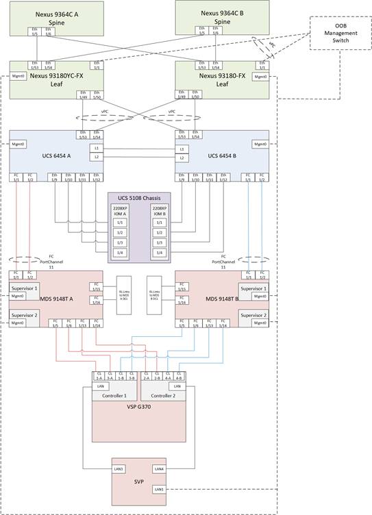
Table 10 Cisco Nexus 93180YC-FX A Cabling Information for DC2
| Local Device |
Local Port |
Connection |
Remote Device |
Remote Port |
| Cisco Nexus 93180YC-FX A |
Eth1/1 |
GbE |
GbE |
Any |
| Eth1/49 |
40GbE |
Cisco UCS 6454 FI A |
Eth 1/53 |
|
| Eth1/50 |
40GbE |
Cisco UCS 6454 FI B |
Eth 1/53 |
|
| Eth1/53 |
40GbE or 100GbE |
Cisco 9364C A (Spine) |
Eth 1/5 |
|
| Eth1/54 |
40GbE or 100GbE |
Cisco 9364C B (Spine) |
Eth 1/5 |
|
| MGMT0 |
GbE |
GbE management switch |
Any |
Table 11 Cisco Nexus 93180YC-FX B Cabling Information for DC2
| Local Device |
Local Port |
Connection |
Remote Device |
Remote Port |
| Cisco Nexus 93180YC-FX B |
Eth1/1 |
GbE |
GbE |
Any |
| Eth1/49 |
40GbE |
Cisco UCS 6454 FI A |
Eth 1/54 |
|
| Eth1/50 |
40GbE |
Cisco UCS 6454 FI B |
Eth 1/54 |
|
| Eth1/53 |
40GbE or 100GbE |
Cisco 9364C A (Spine) |
Eth 1/6 |
|
| Eth1/54 |
40GbE or 100GbE |
Cisco 9364C B (Spine) |
Eth 1/6 |
|
| MGMT0 |
GbE |
GbE management switch |
Any |
![]() The connections for the 93180YC-FX switches to the Cisco UCS 6454 are using 40G ports in these cabling diagrams instead of the more readily available 25G ports from each platform. This is not a requirement, but intends to show that there is some potential capacity to use the higher bandwidth ports in this topology. Prior to use in this manner, the 40G 93180YC-FX ports will need to be converted to Downlink ports from the APIC.
The connections for the 93180YC-FX switches to the Cisco UCS 6454 are using 40G ports in these cabling diagrams instead of the more readily available 25G ports from each platform. This is not a requirement, but intends to show that there is some potential capacity to use the higher bandwidth ports in this topology. Prior to use in this manner, the 40G 93180YC-FX ports will need to be converted to Downlink ports from the APIC.
Table 12 Cisco UCS 6454 FI A Cabling Information for DC2
| Local Device |
Local Port |
Connection |
Remote Device |
Remote Port |
| Cisco UCS 6454 FI A |
FC 1/1 |
32Gb FC |
MDS 9148T A |
FC1/1 |
| FC 1/2 |
32Gb FC |
MDS 9148T A |
FC1/2 |
|
| Eth1/9 |
10GbE |
Cisco UCS Chassis 2208XP FEX A |
IOM 1/1 |
|
| Eth1/10 |
10GbE |
Cisco UCS Chassis 2208XP FEX A |
IOM 1/2 |
|
| Eth1/11 |
10GbE |
Cisco UCS Chassis 2208XP FEX A |
IOM 1/3 |
|
| Eth1/12 |
10GbE |
Cisco UCS Chassis 2208XP FEX A |
IOM 1/4 |
|
| Eth1/53 |
25GbE |
Cisco Nexus 93180YC-FX A |
Eth1/49 |
|
| Eth1/54 |
25GbE |
Cisco Nexus 93180YC-FX B |
Eth1/49 |
|
| L1 |
GbE |
Cisco UCS 6454 FI B |
L1 |
|
| L2 |
GbE |
Cisco UCS 6454 FI B |
L2 |
|
| MGMT0 |
GbE |
GbE management switch |
Any |
Table 13 Cisco UCS 6454 FI B Cabling Information for Cisco UCS 6454 to VSP G370
| Local Device |
Local Port |
Connection |
Remote Device |
Remote Port |
| Cisco UCS 6454 FI B |
FC 1/1 |
32Gb FC |
MDS 9148T B |
FC1/1 |
| FC 1/2 |
32Gb FC |
MDS 9148T B |
FC1/2 |
|
| Eth1/9 |
10GbE |
Cisco UCS Chassis 2208XP FEX B |
IOM 1/1 |
|
| Eth1/10 |
10GbE |
Cisco UCS Chassis 2208XP FEX B |
IOM 1/2 |
|
| Eth1/11 |
10GbE |
Cisco UCS Chassis 2208XP FEX B |
IOM 1/3 |
|
| Eth1/12 |
10GbE |
Cisco UCS Chassis 2208XP FEX B |
IOM 1/4 |
|
| Eth1/53 |
25GbE |
Cisco Nexus 93180YC-FX A |
Eth1/50 |
|
| Eth1/54 |
25GbE |
Cisco Nexus 93180YC-FX B |
Eth1/50 |
|
| L1 |
GbE |
Cisco UCS 6454 FI B |
L1 |
|
| L2 |
GbE |
Cisco UCS 6454 FI B |
L2 |
|
| MGMT0 |
GbE |
GbE management switch |
Any |
Table 14 Cisco MDS 9148 T A Cabling Information for Cisco UCS 6454 to VSP G370
| Local Device |
Local Port |
Connection |
Remote Device |
Remote Port |
| Cisco MDS 9148 T A |
FC 1/1 |
32Gb FC |
Cisco UCS 6454 FI A |
FC1/1 |
| FC 1/2 |
32Gb FC |
Cisco UCS 6454 FI A |
FC1/2 |
|
| FC 1/5 |
32Gb FC |
VSP G370 Controller 1 |
CL1-A |
|
| FC 1/6 |
32Gb FC |
VSP G370 Controller 2 |
CL2-B |
|
| FC 1/13 |
32Gb FC |
VSP G370 Controller 1 |
CL3-A |
|
| FC 1/14 |
32Gb FC |
VSP G370 Controller 2 |
CL2-A |
|
| FC 1/15 |
32Gb FC |
MDS 9706 A |
FC 1/15 |
|
| FC 1/16 |
32Gb FC |
MDS 9706 A |
FC 1/16 |
|
| Sup1 MGMT0 |
GbE |
GbE management switch |
Any |
|
| Sup2 MGMT0 |
GbE |
GbE management switch |
Any |
Table 15 Cisco MDS 9148 T B Cabling Information for Cisco UCS 6454 to VSP G370
| Local Device |
Local Port |
Connection |
Remote Device |
Remote Port |
| Cisco MDS 9148 T B |
FC 1/1 |
32Gb FC |
Cisco UCS 6454 FI B |
FC1/1 |
| FC 1/2 |
32Gb FC |
Cisco UCS 6454 FI B |
FC1/2 |
|
| FC 1/5 |
32Gb FC |
VSP G370 Controller 1 |
CL3-B |
|
| FC 1/6 |
32Gb FC |
VSP G370 Controller 2 |
CL4-A |
|
| FC 1/13 |
32Gb FC |
VSP G370 Controller 1 |
CL1-B |
|
| FC 1/14 |
32Gb FC |
VSP G370 Controller 2 |
CL4-B |
|
| FC 1/15 |
32Gb FC |
MDS 9706 B |
FC 1/15 |
Cisco ACI Multi-Pod Deployment
The Adaptive Solutions Stretched Data Center leverages a Cisco Multi-Pod ACI fabric design to extend the ACI fabric and the vSphere cluster across two data centers to provide business continuity in the event of a disaster. The ACI Pods can be in the same data center location or in different geographical sites. This design assumes the two Pods are in two different geographical locations that was validated in the Cisco labs using a 75km fiber spool to interconnect the data centers.
This section provides detailed procedures for setting up the Cisco ACI Multi-Pod Fabric. An Inter-Pod network is first deployed to provide connectivity between data centers, followed by the ACI fabric in the second DC location.
The procedures outlined in this section are specific to deploying a Cisco ACI Multi-Pod fabric.
Prerequisites
Before ACI Multi-Pod can be deployed, the first ACI fabric (or Pod-1) should be up and running with Spine switches, Leaf switches and APICs.
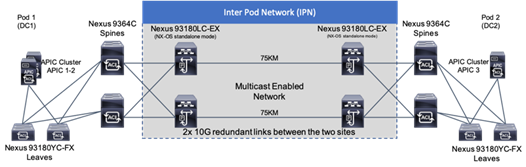
Topology
Figure 20 shows the connectivity between Pods through the IPN and the connectivity from each Pod to the IPN. The connectivity between IPN devices uses 10GbE but the Spine switches in each Pod connect to the IPN devices using 40GbE links. Multiple nodes and links are used from each Pod to IPN and between IPNs to provide a redundant paths between Pods in the event of failures.
Figure 20 ACI Multi-Pod Fabric
Deployment Overview
A high-level overview of the steps involved in deploying an ACI Multi-Pod fabric is summarized below.
Physical Connectivity
The following are the steps involved to set up the physical connectivity:
· Complete the physical connectivity within the Inter-Pod Network (IPN) to provide connectivity between the sites.
· Deploy Spine switches, Leaf switches and APIC(s) in the second ACI Pod. For discovery and auto-provisioning of the fabric in a new Pod, a Spine switch must have at least one link up to a Leaf switch.
· Complete the physical connectivity to connect Spine switches to the IPN in each Pod. It is not necessary to connect all Spines in a Pod to the IPN. For redundancy, two Spines in each Pod should be connected to the IPN. The connected Spine switches will be seen as equal cost paths to the Pod TEP addresses so connecting more Spine switches to the IPN also increases the number of Equal-Cost Multi-Paths (ECMP) routes to Pod networks. This leads to a greater distribution of traffic load.
Deploy Inter-Pod Network (IPN)
The following are the steps involved to deploy the inter-pod network:
· (Optional) Configure a VRF for ACI Multi-Pod traffic on all IPN devices and put the relevant interfaces in the VRF. This isolates the ACI Multi-Pod traffic and protects the ACI underlay network that is now exposed through the IPN. The IPN can be thought of as an extension of the ACI underlay infrastructure in each Pod. The underlay is necessary for establishing VXLAN tunnels between leaf switches and spine switches in each Pod. VXLAN tunnels enable seamless forwarding of Layer 2 and Layer 3 data plane traffic between Pods. The VXLAN overlay is essential for ensuring that the interconnected Pods function as a single ACI fabric.
· Configure Layer 2 encapsulation, Layer 2 protocols (LLDP, CDP), MTU (Jumbo) and IP addressing on relevant interfaces of the IPN devices that provide connectivity within the IPN, and between the IPN and Spines in each Pod. The Spine switches will tag all traffic towards the IPN using VLAN 4. Therefore, IPN devices must be configured for trunking using VLAN 4 on the interfaces connecting to the Spine. Enabling LLDP (preferred) or CDP on IPN interfaces is recommended for determining which ports connect to which devices. Encapsulating traffic in VXLAN adds 50 Bytes of overhead so in order to transport Jumbo (9000 Bytes) frames from endpoints across the IPN, the MTU on the IPN interfaces should be set to at least 50 Bytes higher to avoid fragmentation. MTU used in validation is 9216B as it is commonly used as a default jumbo MTU on many Cisco platforms, including Cisco UCS.
· Enable routing within the IPN and on the connections to Spines to advertise TEP pools between Pods. Each Pod uses a unique TEP pool that must be advertised to the other Pod in order to establish VXLAN Tunnels from one Pod to the other. The Spines in each Pod that connect to the IPN also use Proxy TEP addressing that are also advertised to the other Pods. The proxy TEP addressing enables each Spine to advertise equal cost routes for the Pod subnets to the IPN routers. IPN will use the ECMP to the Spines to distribute traffic to the Pod subnets. Loopback interfaces are used on IPN nodes are used as the router-id for the routing protocol. Currently, OSPFv2 is the only routing protocol supported. Note that underlay infrastructure in an ACI Pod uses ISIS and not OSPF. If the IPN is an extensive L3 network that is already using another routing protocol, it is not necessary to use OSPF everywhere in the IPN – it is only necessary between the Spine switches and IPN devices.
· Enable IP Multicast routing using Bidirectional PIM (BIDIR-PIM) to forward Broadcast, Unknown Unicast and Multicast (BUM) traffic between Pods. This is necessary when endpoints in the same Bridge Domain are distributed across both Pods, to enable seamless East-West (DC1 to DC2) communication between endpoints for multi-destination or non-unicast traffic. BUM traffic is encapsulated in a VXLAN multicast frame to transport it within or between Pods. In an ACI fabric, a multicast traffic within each Bridge Domain is sent to a unique IP multicast group address. The multicast address for the bridge domain is assigned when the bridge domain is first defined in ACI. The address is allocated from a pool of multicast addresses, known as Global IP Outside (GIPo) in ACI. To forward BUM traffic between Pods, the IPN needs to support IP multicast, specifically BIDIR-PIM. In ACI Multi-Pod, when a Bridge Domain is activated within a Pod, an IGMP Join is forwarded to the IPN to receive BUM traffic from remote endpoints in the same Pod. The multicast address pool used for BUM traffic for bridge domains that span the IPN can be the same as the infrastructure GIPo range used within a Pod or different pool can be allocated for this. BIDIR-PIM requires a Rendezvous Point (RP) to be defined. For RP resiliency, a phantom RP can be used. For distributing the RP load,
· Configure DHCP Relay on IPN devices to enable auto-configuration of Spines and APICs in Pod-2 from Pod-1.
Setup ACI Fabric for Multi-Pod
The following are the steps involved to set up the ACI fabric for Multi-Pod:
· Configure IP connectivity to connect Spine Interfaces to IPN devices in Pod-1.
· Configure Routing Protocols (OSPF, BGP) on the Spine Switches. OSPF will provide IP reachability between Pods, specifically between TEP address pools in each Pod. ACI Fabric will redistribute routes from IS-IS used within each Pod to OSPF and vice-versa. This effectively extends the underlay network (VRF overlay-1 in ACI Fabric) to the IPN. BGP will be used to advertise learned MAC and IP addresses of endpoints and their locations. The endpoint information is maintained on separate Counsel of Oracle Protocol (COOP) database on Spine switches on each Pod. Endpoints learned on each local Pod is advertised across the BGP-EVPN peering between Pods. The peering is directly between Spine switches in the Pods. When multiple Pods are connected across the IPN, BGP route-reflectors can be deployed in the IPN rather than direct peering between Pods.
· Configure External TEP Addresses for Spine switches to use for Spine-to-Spine connections across the IPN.
· Add a second Pod to the ACI fabric.
Setup Pod-2 Spine Switches, Leaf Switches, and APIC(s)
The following are the steps involved to set up the Pod-2 spine switches, leaf switches, and APIC(s):
· Configure ACI Fabric access policies to enable connectivity from Pod-1 Spines switches to the IPN.
· Configure newly discovered Spine and Leaf switches in Pod-2 from the first Pod.
· Configure ACI Fabric Access Policies to enable connectivity from Pod-2 Spines switches to the IPN.
· Deploy APIC(s) in Pod-2 to the APIC cluster that manages the fabric.
For additional information about ACI Multi-Pod, see the References section of this document and the ACI product documentation.
Deployment Guidelines
The following are the deployment guidelines:
· IPN must support an MTU of 50 Bytes higher than the MTU used by the endpoints in the deployment. In this design, the ACI Multi-Pod Fabric uses, by default, an MTU of 9000 Bytes or Jumbo frames for vMotion traffic. It is also possible for other (for example, Management, Applications) traffic to use Jumbo frames. The minimum MTU the IPN must support is therefore, 9050 Bytes but 9216 Bytes is recommended, in order to keep it consistent with default MTU on other Cisco platforms such as Cisco UCS.
· ACI Multi-Pod Fabric uses a VLAN ID of 4 for connectivity between Spine Switches and IPN devices in each Pod. This is system defined and cannot be changed – the IPN devices connecting to the Spines must therefore be configured to use VLAN 4.
· IPN device must support a BIDIR-PIM range of at least /15. First generation Nexus 9000 series switches cannot be used as IPN devices as the ASICS used on these support a max BIDIR-PIM range of /24.
· For auto-discovery and auto-configuration of newly added Spine switches to work, at least one Leaf switch must be online and connected to the Spine switch in the remote Pod. The Spine switch should be able to see the Leaf switch via LLDP.
· A Multi-Pod ACI fabric deployment requires the 239.255.255.240 (System GIPo) to be configured as a BIDIR-PIM range on the IPN devices. This configuration is not required when using the Infra GIPo as System GIPo feature. The APIC and switches must be running releases that support this feature.
· Spine switches from each Pod cannot be directly connected to each other – they must go through at least one IPN router/switch.
· It is not necessary to connect all Spines switches in a Pod to the IPN. If possible, connect at least two Spine switches from each Pod to the IPN to provide node redundancy in the event of a Spine switch failure. Traffic is distributed across all the spine switches that are connected to the IPN so more spine switches can be connected to distribute the load even further.
Deploy Inter-Pod Network
This section provides the configuration for deploying Inter-Pod switches that provide Pod-to-Pod connectivity. The IPN is not managed by the APIC. IPN can be thought of as an extension of the ACI underlay network. IPN devices must be enabled for L3 forwarding with VRF Lite (recommended), OSPF, DHCP Relay and BIDIR-PIM. LACP is also required when link bundling is deployed. LLDP is optional but recommended to verify connectivity to peers and ports used for the connection.
Deployment Overview
The high-level steps involved in the setting up the Inter-Pod Network is as follows:
· Complete the physical connectivity to connect devices in the IPN, to IPN devices in remote Pod and to Spine switches in local Pod
· Identify the information required to setup the IPN
· Configure IPN Devices in Pod-1 (DC1)
· Configure IPN Devices in Pod-2 (DC2)
Physical Connectivity - Inter-Pod Network
Figure 21 illustrates the IPN connectivity between IPN devices and to Spine switches in each Pod. The connectivity between IPN devices uses 10GbE and 40GbE to Spine switches.
Figure 21 Inter-Pod Network Connectivity
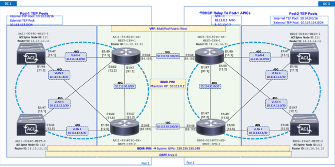
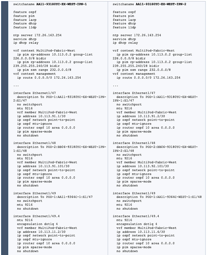
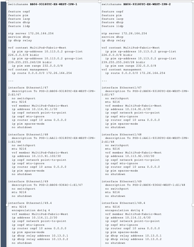
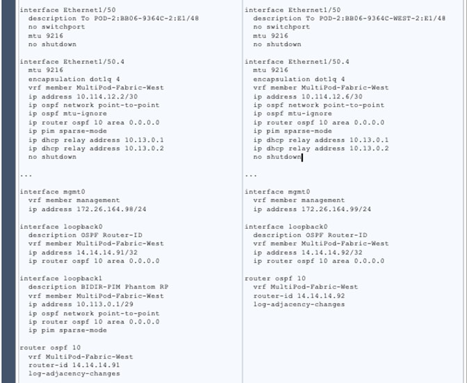
Table 16 Configure IPN Devices in Pod-1 and Pod-2

Setup ACI Fabric for Multi-Pod – Using Configuration Wizard
In APIC Release 4.0(1) and higher, ACI Multi-Pod can be deployed using a configuration wizard that configures the fabric for Multi-Pod.
Prerequisites
The Inter-Pod network should be setup prior to configuring the ACI fabric for Multi-Pod.
Deployment Overview
Deploying ACI Multi-Pod using the APIC Configuration Wizard consists of the following high-level activities:
· Configure Interpod Connectivity - For connecting the first Pod or site to IPN and setting up Multi-Pod
· Add Physical Pod - For adding a second Pod or site in the Multi-Pod setup
The Configure Interpod Connectivity portion of the wizard is for setting up the first Pod or site (Pod-1) for the following:
· IP Connectivity from Spines in Pod-1 to the Inter-Pod network. This includes configuring the Spine interfaces that connect to the IPN for IP connectivity. The APIC on the back-end will take the minimal information provided to the wizard, to configure the necessary fabric access policies for connecting devices to the ACI fabric. This includes configuration of interface and switch-level, policies and profiles on the Spines connecting to the IPN.
· Routing Protocols to enable IP Routing on the Spines in Pod-1 towards the IPN. This includes OSPF-based underlay network for exchanging routes between the Pods and MP-BGP based overlay network for exchanging endpoint location information using MP-BGP EVPN.
· External TEP addressing for Pod-1 to communicate with other Pods or sites. This includes specifying a routable External TEP Pool for the first Pod or site.
The Add Physical Pod portion of the wizard is for adding the second Pod or site (Pod-2) and consists of the following:
· Pod Fabric information for creating a second Pod. This includes specifying a unique Pod ID and TEP Pool for the new Pod. It also includes parameters for configuring IP connectivity from Spines in Pod-2 to the Inter-Pod network, similar to the information used in Pod-1 for connecting the Spines in Pod-1 to IPN.
· External TEP addressing for Pod-2 to communicate with other Pods or sites. This includes specifying a routable External TEP Pool for the second Pod or site.
· Configure DHCP Relay on the IPN devices to point to the APIC TEP IP Addresses.
· Configure OSPF interface policies for Pod-2 Spine switches that connect to the IPN
The setup information and deployment steps for configuring Interpod connectivity and adding a Physical Pod using the Wizard are covered in the next sections.
Configure Inter-Pod Connectivity
Follow the procedures in this section to configure Inter-Pod connectivity to connect the Spine switches in Pod-1 to IPN and set up ACI Fabric for Multi-Pod.
IP Connectivity
IP Connectivity section of the wizard provides the physical interface and IP configuration on the Spines switches in Pod-1 that connect to IPN devices. The parameters used in this CVD for this portion of the configuration is provided in Table 17 .
Table 17 IP Connectivity Information for Pod-1
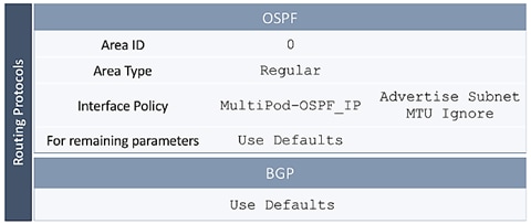
Routing Protocols
Routing Protocols section of the wizard provides the routing protocol (OSPF, BGP) configuration on the Spine switches in Pod-1 that connect to IPN to enable the OSPF based underlay network and MP-BGP based overlay. The parameters used in this CVD for this portion of the configuration is provided in Table 18 .
Table 18 Routing Protocols Information for Pod-1
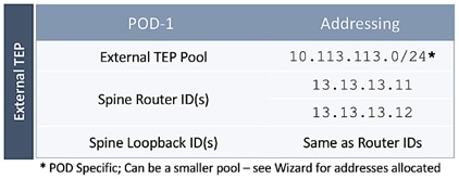
External TEP
External TEP section of the wizard provides the addressing configuration on the Spine switches to enabled Pod-to-Pod connectivity across the Inter-Pod network. The parameters used in this CVD for this portion of the configuration is provided in the Table 19 .
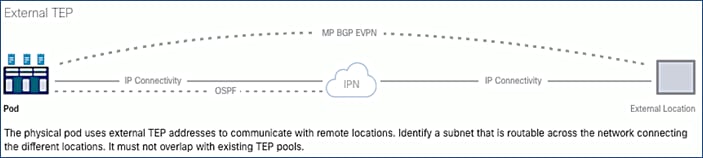
Table 19 External TEP Information for Pod-1
Run Configuration Wizard for IPN Connectivity
To enable IPN connectivity for the Spines in Pod-1, follow these steps:
1. Use a browser to navigate to the APIC GUI. Log in using admin account.
2. From the top navigation menu, select Fabric > Inventory.
3. From the left navigation pane, expand and select Quick Start > Add Pod.
4. From the right window, click Add Pod.
5. In the pop-up window for Configure Interpod Connectivity wizard, review the Overview. Collect the Setup Information for IP Connectivity, Routing Protocols and External TEP. For the parameters used in validating this CVD, see the Setup Information for Pod-1 tables in the previous section. Click Get Started.
6. In the Step 2 > IP Connectivity window of the wizard, for each Spine switch connecting to IPN devices, specify the Spine ID (for example, 111), interface (for example, e1/47), IP Address (for example, 10.13.11.1/30) and MTU (for example, 9216) that matches the MTU on the interfaces on the IPN devices that these interfaces connect to. ACI Multi-Pod requires a minimum of 9150 bytes but many Cisco devices incudes the IP header in the MTU specified and therefore, 9216 bytes is used.
7. Click [+] to the right of the MTU to add more interfaces.
8. Click [+] to the right of the Spine ID to add more Spine switches.
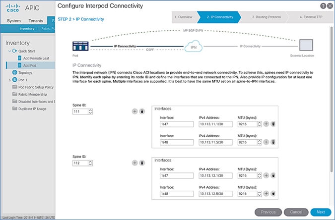
9. Click Next.
10. In the Step 3 > Routing Protocol window of the wizard, for the Spine switches in Pod-1 connecting to the IPN devices, leave checkbox Use Defaults enabled, specify the Area ID (for example, 0), Area Type (for example, Regular) and for Interface Policy, click the drop-down list and select Create OSPF Interface Policy.
11. In the Create OSPF Interface Policy pop-up window, specify a Name (for example, MultiPod-OSPF_IP) for the interface policy. Specify the OSPF Network Type (for example, Point-to-point). For Interface Controls, select the checkbox for Advertise subnet and MTU ignore.
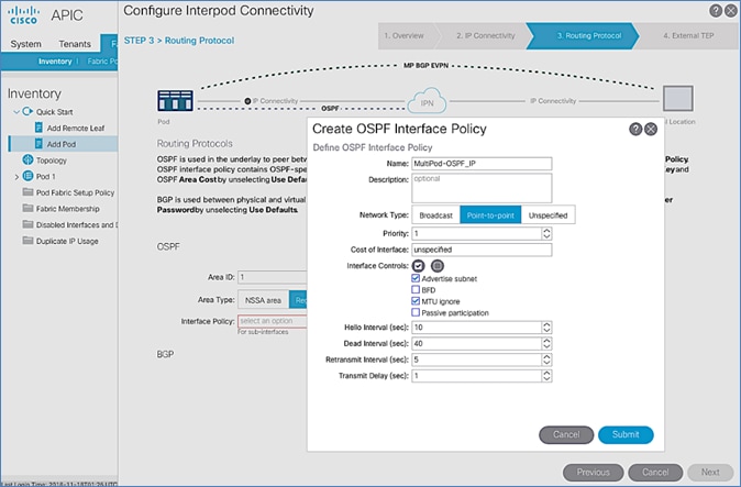
12. Click Submit.
13. For BGP, leave the Use Defaults checkbox enabled.
![]()
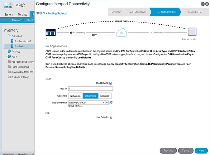
14. Click Next.
15. In the Step 3 > External TEP section of the wizard, for the Spine switches in Pod-1 connecting to the IPN devices, leave the checkbox Use Defaults enabled. Specify the External TEP Pool (for example, 10.113.113.0/24) and Router IDs (for example, 13.13.13.11, 13.13.13.12) for the Spines.
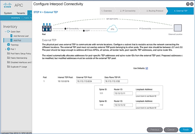
16. Click Finish to complete the Inter-Pod connectivity setup for Spine switches in the first Pod or site (Pod-1).
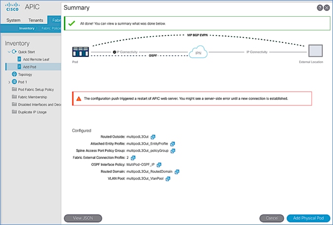
17. In the Summary window, review the information provided.
18. (Optional) Click Add Physical Pod to continue to the next stage of the configuration now or come back to this at a later time. See the next section to add physical pods and to add the second pod or site.
Add Physical Pod – Second Pod or Site (Pod-2)
Table 20 Pod Configuration
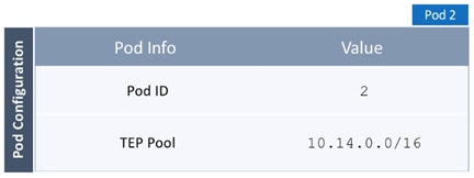
Table 21 IP Connectivity
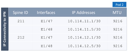
Table 22 External TEP
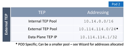
![]() To add the second Pod in the ACI Multi-Pod setup, follow the steps below. If continuing immediately from the previous section, click Add Physical Pod from the last step and proceed directly to step 5 below.
To add the second Pod in the ACI Multi-Pod setup, follow the steps below. If continuing immediately from the previous section, click Add Physical Pod from the last step and proceed directly to step 5 below.
1. Use a browser to navigate to the APIC GUI. Log in using the admin account.
2. From the top navigation menu, select Fabric > Inventory.
3. From the left navigation pane, expand and select Quick Start > Add Pod.
4. From the right window, click Add Pod.
5. In the pop-up window for Add Physical Pod wizard, review the Overview. Collect the Setup Information for the new Pod, IP Connectivity and External TEP. For the parameters used in validating this CVD, see the Setup Information for Pod-2 section. Click Get Started.
6. In the Step 2 > Pod Fabric window of the wizard, for the new Pod, specify a Pod ID (for example, 2) and Pod TEP Pool (for example, 10.14.0.0/16).
![]() Please make sure TEP Pool subnet is correct and not overlapping.
Please make sure TEP Pool subnet is correct and not overlapping.
7. For each Spine switch in Pod-2 connecting to IPN devices, specify the Spine ID (for example, 211), interface (for example, e1/47), IP Address (for example, 10.14.11.1/30) and MTU (for example, 9216) that matches the MTU on the interfaces on the IPN devices that these interfaces connect to. ACI Multi-Pod requires a minimum of 9150 bytes but many Cisco devices includes the IP header in the MTU specified and therefore, 9216 bytes is used.
8. Click [+] to the right of the MTU field to add more interfaces.
9. Click [+] to the right of the Spine ID to add more Spine switches.
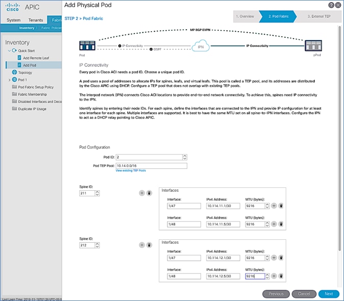
10. In the Step 3 > External TEP window of the wizard, for the Spine switches in Pod-2 connecting to the IPN devices, leave checkbox Use Defaults enabled. Specify the External TEP Pool for Pod-2 (for example, 10.114.114.0/24) and Router IDs (for example, 14.14.14.11, 14.14.14.12) for the Spines.
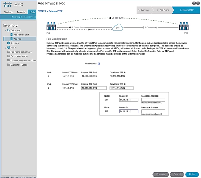
11. Click Finish to complete the Inter-Pod connectivity setup for the Spine switches in the second Pod or site (Pod-2).
12. In the Summary window, review the information provided.
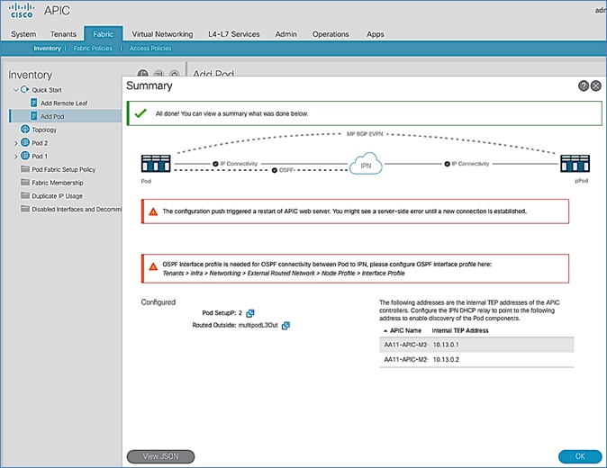
13. Proceed to the next section to configure DHCP relay on the IPN devices if it hasn’t been configured yet. Confirm that the DHCP relay points to the APIC IP addresses listed in the above Summary window.
Configure DHCP Relay on IPN Devices
Per the recommendations from the Configuration Wizard Summary page, add DHCP relay statements on IPN devices. DHCP should be relayed to the TEP IP Addresses of the APICs in Pod-1 and should match the addresses listed on the same Summary page. The configuration should be added to Pod-facing interfaces on IPN devices.
![]() This was completed in the Deploy Inter-Pod Network section but verify the APIC IP addresses and the interfaces to which it is applied.
This was completed in the Deploy Inter-Pod Network section but verify the APIC IP addresses and the interfaces to which it is applied.
Proceed to the next section to configure the OSPF Interface Profile as per the message displayed on the Summary page.
Configure OSPF Interface Profile for Spines in Pod-2
Per the Summary of recommendations at the end of the Configuration Wizard for adding a Pod, create the OSPF Interface Profiles for all Spine switches that connect to the IPN.
To create the OSPF Interface Profile, follow these steps:
1. From the top navigation menu, select Tenants > infra.
2. From the left navigation pane, expand and select Tenant Infra > Networking > External Routed Networks > multipodL3Out > Logical Node Profiles.
3. Select the Node profile (for example, LNodeP_211) for the first Pod-2 Spine switch.
4. Expand the Node profile for the selected node and select the profile for that Spine node. Right-click and select Create OSPF Interface Profile from the menu.
5. In the pop-up window for Add Physical Pod wizard, navigate to Tenants > Infra from the top navigation menu.
6. For the OSPF Policy, select the previously created policy from the drop-down list.
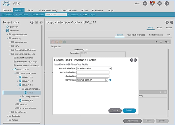
7. Click Submit to complete.
8. Repeat steps 1-7 for the second Spine node in Pod-2 as shown below.
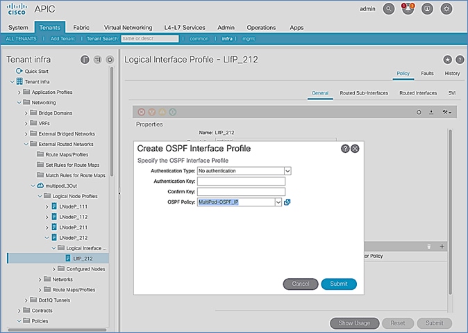
9. Click Submit to complete.
Setup Fabric Access Policies for Spine Switches in Pod-1
In ACI, access policies define the port configuration. In this section, access policies are configured for all interfaces on the spine switches in Pod-1 that connect to the IPN. The access policies enable connectivity between the Spine switches and IPN in Pod-1. The access policies are grouped and applied to specific interfaces and switches using interface and switch profiles respectively.
Deployment Overview
The deployment workflow for configuring Spines to connect to IPN is similar to configuring ACI Leaf switches for connectivity to access layer devices such as Cisco UCS. The configuration in both cases is done through Fabric Access Policies. The workflow for creating Fabric Access Policies for connecting Spines to IPN devices in Pod-1 is shown in Figure 22.
Figure 22 Fabric Access Policies – For Spine Switch Connectivity to IPN in Pod-1
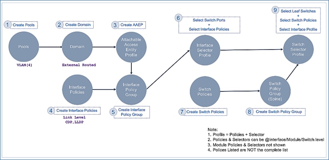
Setup Information
The information for configuring fabric access policies to connect Spine switches in Pod-1 to IPN is provided below.
![]() VLAN Pool, L3 Routed Domain, AAEP, and Interface Policy Group listed below are configured by the Configuration Wizard during the Multi-Pod setup. For details, see section Setup ACI Fabric for Multi-Pod – Using Configuration Wizard.
VLAN Pool, L3 Routed Domain, AAEP, and Interface Policy Group listed below are configured by the Configuration Wizard during the Multi-Pod setup. For details, see section Setup ACI Fabric for Multi-Pod – Using Configuration Wizard.
Figure 23 Setup Information – Fabric Access Policies on Pod-1 Spine Switches
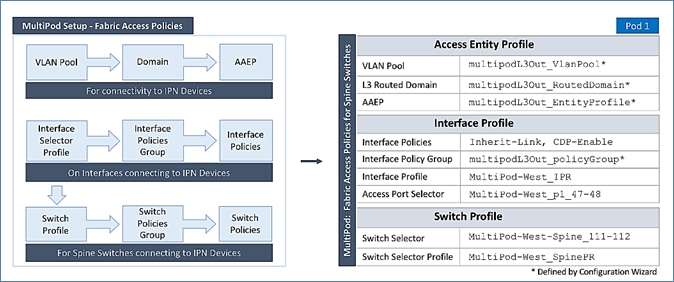
Deployment Steps
Complete the procedures outlined in this section to configure access policies on Spine switch interfaces to enable connectivity to IPN in Pod-1. Unlike other access layer connections in this design, the access layer policies here are applied to interfaces on Spine switches and represent fabric-to-fabric connectivity across a L3 network.
Update Interface Policy Group
The interface policy group was created by the APIC configuration wizard as a part of the Multi-Pod setup. In this section, the policy group is updated to include some additional policies. The policies are among the pre-configured Fabric Access Policies completed earlier in the setup.
To update the interface policy group, follow these steps:
1. Use a browser to navigate to the APIC GUI. Log in using the admin account.
2. From the top menu, select Fabric > Access Policies.
3. From the left navigation pane, select and expand Policies > Interfaces > Spine Interfaces > Policy Groups.
4. Select the previously created policy group (for example, multipodL3Out_policyGroup).
5. In the right window pane, for Link Level Policy, select the Inherit-Link policy that was created earlier. For CDP Policy, select CDP-Enabled.
![]() Enabling CDP is optional. LLDP should be enabled by default.
Enabling CDP is optional. LLDP should be enabled by default.
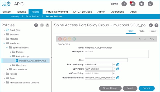
6. Click Submit and Submit Changes to complete.
Create Interface (Selector) Profile for Spine Connectivity to IPN
The same interface profile can be re-used to configure other access layer connections that share the same interface selectors. In this design, Pod-2 Spine switches connect to the IPN on the same ports as Pod-1 switches and therefore will use this profile.
To create interface (selector) profile for the access layer connections from Spine switches to IPN in Pod-1, follow these steps:
1. Use a browser to navigate to the APIC GUI. Log in using the admin account.
2. From the top menu, select Fabric > Access Policies.
3. From the left navigation pane, select and expand Policies > Interfaces > Spine Interfaces > Profiles.
4. Right-click Profiles and select Create Spine Interface Profile.
5. In the Create Spine Interface Profile pop-up window, specify a profile Name (for example, MultiPod-West_IPR).
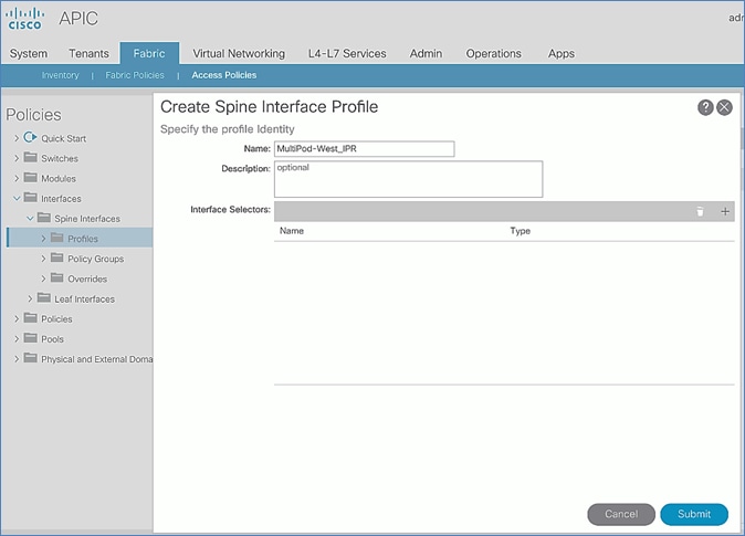
6. For the Interface Selectors, click the [+] on the right-side of the window to select access ports connecting to IPN devices. In the Create Spine Access Port Selector pop-up window, specify a selector Name (for example, MultiPod-West_p1_47-48). For the Interface IDs, add the ports that connect to IPN devices. For Interface Policy Group, select the previously created Interface Policy Group.
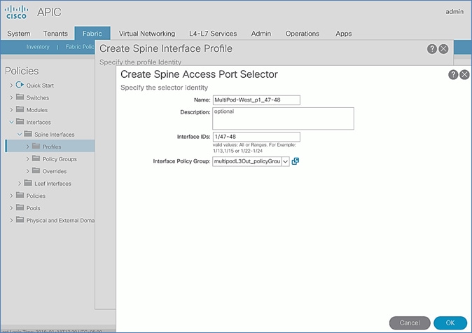
7. Click OK and Submit to complete.
Create Switch Profile for Spine connectivity to IPN
To create Switch profile for the access layer connections from Spine switches to IPN in Pod-1, follow these steps:
1. Use a browser to navigate to the APIC GUI. Log in using admin account.
2. From the top menu, select Fabric > Access Policies.
3. From the left navigation pane, select and expand Policies > Switches > Spine Switches > Profiles.
4. Right-click and select Create Spine Profile.
5. In the Create Spine Profile pop-up window, specify a profile Name (for example, MultiPod-West_SpinePR). For the Spine Selectors, click the [+] on the right-side of the window to select the Spine switches to apply the interface profile to. Specify a selector Name (for example, MultiPod-West-Spine_111-112 and under the Blocks column, select the Spine Switch IDs from the drop-down list (for example, 111,112). Click Update. Click Next.
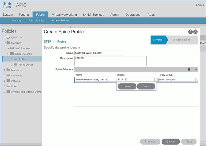
6. In the Step 2 > Associations window, for the Interface Selector Profile, select the previously created Interface Profile.

7. Click Finish to complete.
Deploy ACI Fabric in Pod-2
Deployment Overview
A high-level overview of the steps involved in deploying Pod-2 is summarized below:
· Complete the physical connectivity to connect all the devices in Pod-2. The fabric should have a minimum of two Spine and Leaf switches, and three APICs in a cluster. Since the APIC cluster is part of an ACI Multi-Pod fabric, two APICs are deployed in Pod-1 and one in Pod-2. CIMC management to the APIC in Pod-2 to access the console and out-of-band management connectivity to the switches and APIC should also be in place.
· Deploy Spine and Leaf switches in Pod-1. APICs are connected to the Leaf switches. The leaf switches are also border leaf switches that enable connectivity to networks outside the ACI fabric from Pod-1.
· Setup and configure the third APIC in the cluster. The first two APICs are deployed in Pod-1.
· Configure Out-of-Management (OOB) IP addresses for all switches in Pod-2.
· Configure Pod for NTP, BGP Route Reflector function, Fabric Profiles, and so on.
Physical Connectivity
Complete the cabling required to deploy Pod-2 in the ACI Multi-Pod Fabric as shown in Figure 24. The connectivity for OOB management for all the devices and CIMC management for the third APIC (not shown below) should also be completed.
Figure 24 Physical Connectivity Details for Pod-2
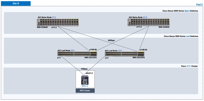
Deploy Spine and Leaf Switches in Pod-2
When the Multi-Pod setup is complete, Pod-2 Spine and Leaf switches should discoverable by the APIC(s) in the first site. In this section, verify the Spines in Pod-2 are being discovered by the APIC(s) in Pod-1. They will be discovered if the IPN connectivity and Multi-Pod setup is correct. Once discovered, the Spines and Leaf switches are added to the ACI Fabric.
Prerequisites
The following are the prerequisites to deploy the spine and leaf switches in Pod-2:
· Confirm that all Spine and Leaf switches in Pod-2 are running software that is compatible with the APIC release running in the ACI Fabric. Failure to do so can impact the discovery and addition of these switches to the Fabric.
· The Spine switches must be connected to at least one Leaf switch before it can be discovered. The Spine switch must be able to see the Leaf switch via LLDP.
Deployment Overview
The high-level steps for deploying Pod-2 switches to the ACI Fabric are summarized below:
· Discover and add Spine switches in Pod-2
· Discover and add Leaf switches in Pod-2
· Configure Out-of-band Management for Pod-2 switches
· Configure NTP for Pod-2 using Out-of-Band Management
· Update BGP Route Reflector Policy with Pod-2 Spine Switches
Table 23 Spine Switches in Pod-2
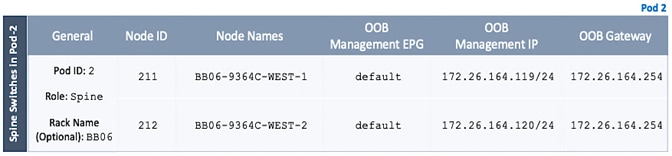
Table 24 Leaf Switches in Pod-2
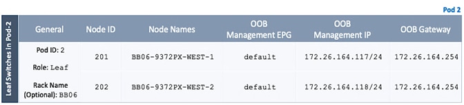
![]() These 9372PX leaves are shown as an example of initial leaves added to the fabric and are used as border leaves for uplinking the APIC and connecting to the non-ACI network. Having the function of these border leaves sitting independent of the production workload leaves is not a requirement, but represents what was configured in the lab environment.
These 9372PX leaves are shown as an example of initial leaves added to the fabric and are used as border leaves for uplinking the APIC and connecting to the non-ACI network. Having the function of these border leaves sitting independent of the production workload leaves is not a requirement, but represents what was configured in the lab environment.
Verify APIC and the Spine Switches In Pod-2
To verify that APIC can see Leaf and Spine switches in Pod-2 to the ACI Fabric, follow these steps:
1. Use a browser to navigate to the APIC GUI. Log in using admin account.
2. From the top menu, select Fabric > Inventory.
3. From the left navigation pane, navigate to Fabric Membership.
4. In the right navigation pane, go to the Nodes Pending Registration tab.
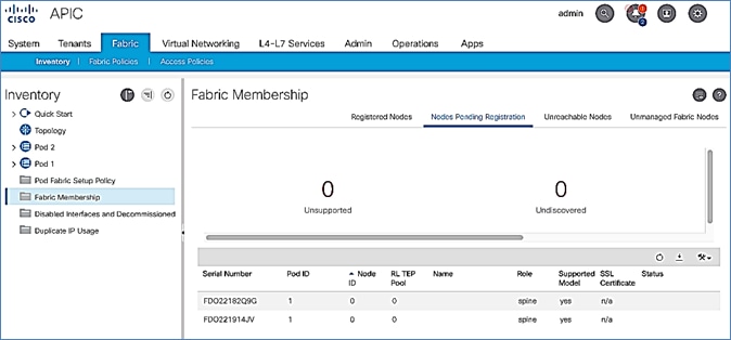
5. Confirm that you see all the Spine switches that are directly connected to the IPN devices.
6. Identify the spine switches based on their serial numbers and collect the corresponding setup information. Proceed to the next section to configure the Spine switches.
Add Spine Switches in Pod-2 to the ACI Fabric
To add spine switches in Pod-2 to the ACI fabric, follow these steps:
1. Use a browser to navigate to the APIC GUI. Log in using admin account.
2. From the top menu, select Fabric > Inventory.
3. From the left navigation pane, navigate to Fabric Membership.
4. In the right navigation pane, go to the Nodes Pending Registration tab.
5. Identify the Serial number of the Spine switch in Pod-2 that should be configured first.
6. Select the switch from the list. Right-click and select Register.
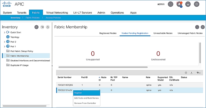
7. In the Register pop-up window, specify the Pod ID (for example, 2), Node Id (for example, 211), Node Name for example, BB06-9364C-WEST-1) and Rack Name (for example, BB06).
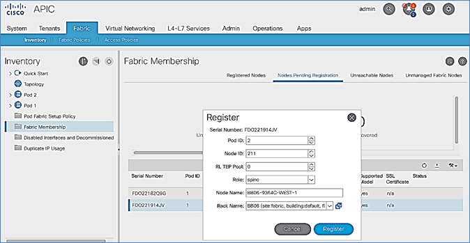
8. Click Register.
9. Click the Registered Nodes tab.
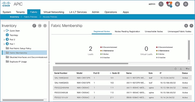
10. The newly configured Spine should show up in the registered list. It should transition to Active status after a few minutes.
11. In the right navigation pane, go to the Nodes Pending Registration tab.
12. You should now see the remaining Spine switches that need to be registered and configured. Note that you will also start to see any discovered Leaf switches that were connected to the Pod-2 Spine. You will configure Leaf switches in the next section after all the Spine switches have been configured.
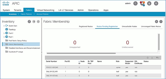
13. Select the next Spine switch in the list and repeat the above steps to register the switch.
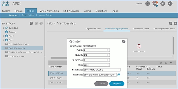
14. Both Pod-2 Spine switches will now show up under the Registered Nodes tab.
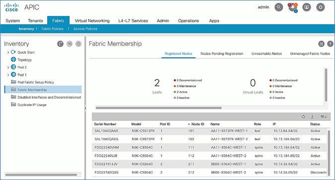
15. In the Nodes Pending Registration tab, you should now see all the Leaf switches that were discovered as a result of registering the Spine switches that they connect to.
Upgrade Firmware on Spine Switches in Pod-2 (Optional)
To upgrade the firmware on the spine switches in Pod-2, follow these steps:
1. From the top menu, navigate to Admin > Firmware.
2. Select the tabs for Infrastructure > Nodes.
3. Check the Current Firmware version column for the newly deployed Spine switches to verify they are compatible with the APIC version running.
4. If an upgrade is not required, proceed to the next section but if an upgrade is required, use the product documentation to upgrade the switches.
Verify that APIC Can See the Leaf Switches In Pod-2
To verify that APIC can see the leaf switches in Pod-2, follow these steps:
1. Use a browser to navigate to the APIC GUI. Log in using admin account.
2. From the top menu, select Fabric > Inventory.
3. From the left navigation pane, navigate to Fabric Membership.
4. In the right navigation pane, go to the Nodes Pending Registration tab.
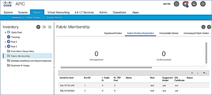
5. Confirm that you see all the Leaf switches in Pod-2.
6. Identify the Leaf switches based on their serial numbers and collect the corresponding setup information. Proceed to the next section to configure the Leaf switches.
Add Leaf Switches in Pod-2 to the ACI Fabric
To add the leaf switches in Pod-2 to the ACI fabric, follow these steps:
1. Use a browser to navigate to the APIC GUI. Log in using admin account.
2. From the top menu, select Fabric > Inventory.
3. From the left navigation pane, navigate to Fabric Membership.
4. In the right navigation pane, go to the Nodes Pending Registration tab.
5. Identify the Serial number of the Leaf switch in Pod-2 that should be configured first.
6. Select the switch from the list. Right-click and select Register.
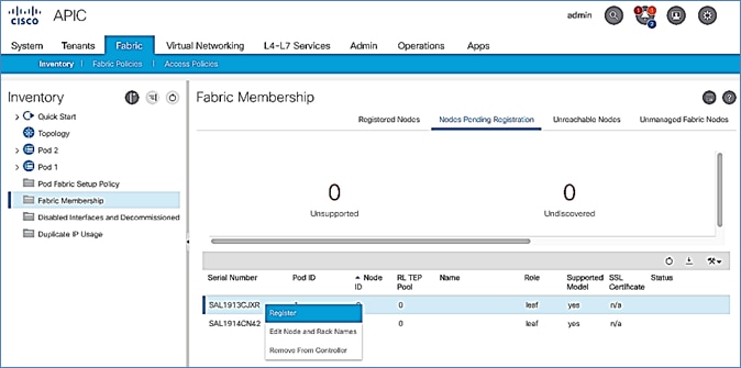
7. In the Register pop-up window, specify the Pod ID (for example, 2), Node Id (for example, 201), Node Name for example, BB06-9372PX-WEST-1) and Rack Name (for example, BB06).
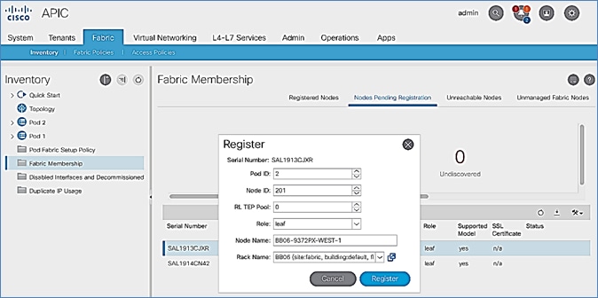
8. Click Register.
9. Click the Registered Nodes tab and the newly configured Leaf switch should now show up in the registered list. It will transition to Active after a few minutes.
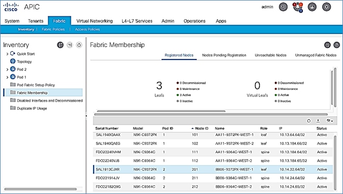
10. In the right navigation pane, click the Nodes Pending Registration tab.
11. Select the next Leaf switch in the list and repeat steps 1-10 to register the switch.
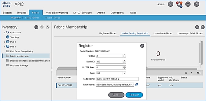
12. All registered Leaf switches will show up under the Registered Nodes tab.
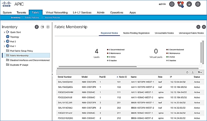
Upgrade Firmware on Leaf Switches in Pod-2 (Optional)
To upgrade the firmware on the leaf switches in Pod-2, follow these steps:
1. From the top menu, navigate to Admin > Firmware.
2. Select the tabs for Infrastructure > Nodes.
3. Check the Current Firmware version column for the newly deployed Leaf switches to verify they are compatible with the APIC version running.
4. If an upgrade is not required, proceed to the next section but if an upgrade is required, use the product documentation to upgrade the switches.
Configure Out-of-Band Management for Pod-2 Switches
To configure out-of-band Management for Pod-2 Spine and Leaf switches, follow these steps using the setup information in Table 23 and Table 24 :
1. Use a browser to navigate to the APIC GUI. Log in using admin account.
2. From the top menu, select Tenants > mgmt.
3. From the left navigation pane, expand and select Tenant mgmt > Node Management Addresses > Static Node Management Addresses.
4. Right-click and select Create Static Node Management Addresses.
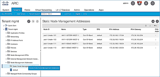
5. In the Create Static Node Management Addresses pop-up window, specify a Node Range (for example, 201-202), for Config: select the box for Out-of-Band Addresses.
6. For Out-of-Band Management EPG, select default from the drop-down list.
7. Specify the Out-of-Band Management IPv4 Address for the first node in the specified range.
8. Specify the Out-of-Band Management IPv4 Gateway.
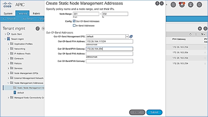
9. Click Submit to complete.
10. Click Yes in the Confirm pop-up window to assign the IP address to the range of nodes specified.
11. Repeat steps 1-10 for the remaining Spine and Leaf switches in Pod-2.
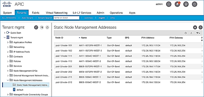
The switches can now be accessed directly using SSH.
Configure NTP for Pod-2 using Out-of-Band Management
To configure NTP for Pod-2, follow these steps using the setup information provided below:
· NTP Policy Name: Pod2-West-NTP_Policy
· NTP Server: 172.26.164.254
· Management EPG: default (Out-of-Band)
1. Use a browser to navigate to the APIC GUI. Log in using admin account.
2. From the top menu, select Fabric > Fabric Policies.
3. From the left navigation pane, navigate to Policies > Pod > Date and Time.
4. Right-click and select Create Date and Time Policy.
5. In the Create Date and Time Policy pop-up window, specify a Name for Pod-2’s NTP Policy. Verify that the Administrative State is enabled.
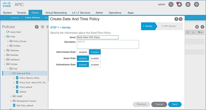
6. Click Next.
7. In Step 2 > NTP Servers, add NTP server(s) for Pod-2 using the [+] to the right of the list of servers.
8. In the Create Providers pop-up window, specify the Hostname/IP of the NTP server in the Name field. If multiple NTP Providers are being created for Pod-2, select the checkbox for Preferred when creating the preferred provider. For the Management EPG, select default (Out-of-Band) from the drop-down list.
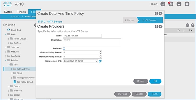
9. Click OK.
10. Click Finish.
![]() The NTP policy is not in effect until it is applied using a Pod Profile.
The NTP policy is not in effect until it is applied using a Pod Profile.
Update BGP Route Reflector Policy for Pod-2
In an ACI fabric with multiple Spine switches, a pair of Spine switches are configured as Route Reflectors (RR) to redistribute routes from external domains into the fabric. In a Multi-Pod ACI fabric, each Pod has a pair of RR nodes. This section provides enabling the RR functionality on Spine switches in Pod-2.
To enable BGP Route Reflector functionality on Spine switches in Pod-2, follow these steps using the setup information provided below:
· BGP Route-Reflector Policy Name: default
· Pod-2 Spine ID: 211,212
1. Use a browser to navigate to the APIC GUI. Log in using admin account.
2. From the top menu, select System > System Settings.
3. From the left navigation pane, navigate to BGP Route Reflector.
4. In the right window pane, in the Route Reflector Nodes section, click the [+] on the right to Create Route Reflector Node.
5. In the Create Route Reflector Node pop-up window, for Spine Node, specify the Node ID (for example, 211) for the first Spine in Pod-2.
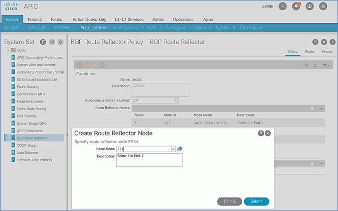
6. Click Submit.
7. Repeat steps 1-6 to add second Spine in Pod-2.
8. You should now see two Spines as Route Reflectors for each Pod in the deployment.
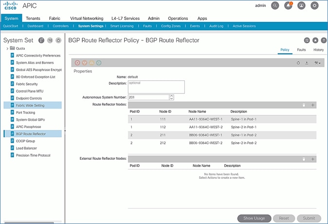
Update Pod Profile to Apply Pod Policies
In ACI, Pod Policies (for example, BGP Route Reflector policy from previous section) are applied through a Pod Profile. A separate Pod Policy Group is used to group policies for each Pod and then they are applied using the Pod Profile. In this design, different NTP servers are used in each Pod. This policy is applied to Pod-2 policy group and then applied to the Pod Profile. A single Pod Profile is used to apply Pod policies for both Pod-1 and Pod-2. This section explains how to apply Pod Policies to Pod-2.
Setup Information
· Pod Policy Group for Pod-2: Pod2-West_PPG
· Pod Selector Name for Pod-2: Pod2-West
· Pod Profile: default
· ID for Pod-2: 2
· Names of Pod Policies to be applied: Pod2-West-NTP_Policy
Deployment Steps
To apply Pod policies on Spine switches in Pod-2, follow these steps:
1. Use a browser to navigate to the APIC GUI. Log in using admin account.
2. From the top menu, select Fabric > Fabric Policies.
3. From the left navigation pane, navigate to Pods > Policy Groups.
4. Right-click and select Create Pod Policy Group, click the [+] on the right to Create Route Reflector Node.
5. In the Create Pod Policy Group pop-up window, for the Name, specify a Pod Policy Name (for example, Pod2-West_PPG). For the Date Time Policy, select the previously created NTP policy for Pod-2 (for example, Pod2-West-NTP_Policy). For the different policies, select the default policy from the drop-down list, including the BGP Route Reflector Policy that was configured in the previous section.
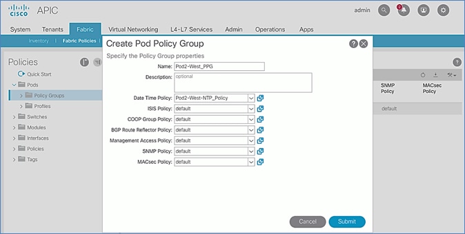
6. Click Submit.
7. From the left navigation pane, navigate to Pods > Profiles > Pod Profile default .
8. In the right window pane, in the Pod Selectors section, click the [+] to add a Pod Selector.
9. In the newly created row, specify a Name (for example, Pod2-West). For Type, select Range. For Blocks, specify the Pod Id for Pod-2 (for example, 2). For Policy Group, select the previously created Policy Group for Pod2 (for example, Pod2-West_PPG).
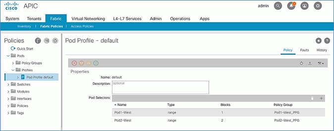
10. Click Submit to apply the Fabric Policies to Pod-2.
Setup Fabric Access Policies for Spine Switches in Pod-2
In ACI, access policies define the port configuration. In this section, access policies are configured for all interfaces on the spine switches in Pod-2 that connect to the IPN. The access policies enable connectivity between the Spine switches and IPN in Pod-2. The access policies are grouped and applied to specific interfaces and switches using interface and switch profiles respectively.
Deployment Overview
The deployment workflow for configuring Spines to connect to IPN is similar to configuring ACI Leaf switches for connectivity to access layer devices such as Cisco UCS. The configuration in both cases is done through Fabric Access Policies. The workflow for creating Fabric Access Policies for connecting Spines to IPN devices in Pod-2 is shown in Figure 25.
Figure 25 Fabric Access Policies – For Spine Switch Connectivity to IPN in Pod-2
Setup Information
The information for configuring fabric access policies to connect Spine switches to IPN in Pod-2 is provided below.
![]() VLAN Pool, L3 Routed Domain, AAEP and Interface Policy Group listed below are configured by the Configuration Wizard during Multi-Pod setup.
VLAN Pool, L3 Routed Domain, AAEP and Interface Policy Group listed below are configured by the Configuration Wizard during Multi-Pod setup.
Figure 26 Setup Information – Fabric Access Policies on Pod-2 Spine Switches
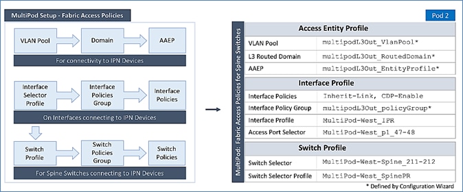
Deployment Steps
Follow the procedures outlined in this section to configure access policies on Spine switch interfaces to enable connectivity to IPN in Pod-2. Pod-2 leverages the same interface profile as Pod-1 to enable connectivity to IPN devices in Pod-2. This is possible because Pod-2 Spine switches connect to the IPN on the same ports and use the same policies as Pod-1 switches in this design, see Fabric Access Policies configuration in Pod-1 for more information.
Update Switch Profile for Spine connectivity to IPN
In this design, the same switch profile is used to configure all Spine switches that connect to the IPN. This is possible because the policies, ports and all other parameters are the same for all Spine switches except that they are all different Spine switches. However, the switch selector profile can be used to select the different switches and apply them to the same switch profile.
To update the switch profile used by Pod-1 Spine switches to include Pod-2 switches, follow these steps:
1. Use a browser to navigate to the APIC GUI. Log in using admin account.
2. From the top menu, select Fabric > Access Policies.
3. From the left navigation pane, select and expand Policies > Switches > Spine Switches > Profiles.
4. Select the previously created profile (for example, MultiPod-West_SpinePR).
5. In the right window pane, for Spine Selectors, click the [+] on the right-side of the window to add Pod-2 Spine switches to apply the interface profile to. Specify a selector Name (for example, MultiPod-West-Spine_211-212 and under the Blocks column, select the Spine Switch IDs from the drop-down list (for example, 211,212). Click Update. Click Next.
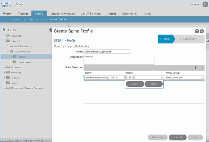
6. In the Step 2 > Associations window, for the Interface Selector Profile, select the previously created Interface Profile.
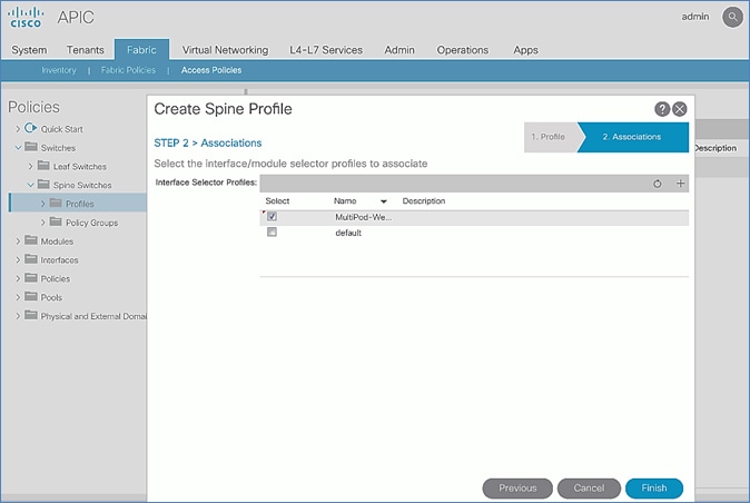
7. Click Finish.
8. Review the switch profile to confirm that Spines in both Pods are selected in the profile.
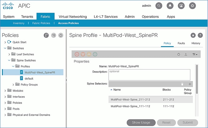
Deploy APIC(s) in Pod-2
This section explains the procedures for deploying an APIC (Pod-2) to the existing APIC (Pod-1) cluster. The new APIC is connected to Pod-2 Leaf switches deployed in the previous section.
![]() For disaster avoidance, at least one APIC should be deployed in Pod-2.
For disaster avoidance, at least one APIC should be deployed in Pod-2.
Prerequisites
The following are the prerequisites to deploy APIC(s) in Pod-2:
· All Spine and Leaf switches in Pod-2 should be part of the ACI Fabric and in Active state. APIC should be redundantly connected to an Active Leaf switch pair.
· Pod-2 APIC should run a compatible server firmware version – see APIC release notes for the recommended server firmware. The server firmware version can be seen from the CIMC GUI. See the Initial Setup of Pod-2 APIC section for the versions used in this CVD.
· APIC in Pod-2 should run the same version of software as other APICs in the cluster APIC cluster. APIC can be upgraded after joining the cluster, but to join the cluster, the software must still be a compatible version.
Deployment Overview
The high-level steps for deploying Pod-2 switches to the ACI Fabric are summarized below:
· Verify that the Pod-2 Spine and Leaf switches are part of the ACI Fabric.
· Complete the initial setup of Pod-2 APIC.
· Verify that the new Pod-2 APIC is part of the APIC cluster.
· Add Pod-2 APIC as a destination for DHCP relay on the IPN devices.
Verify Pod-2 Switches are Part of the ACI Fabric
Table 25 Pod-2 Switches ACI Fabric Information
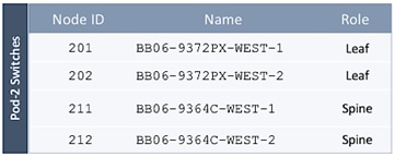
To confirm that the Pod-2 Spine and Leaf switches are part of the ACI Fabric, follow these steps:
1. Use a browser to navigate to the APIC GUI. Log in using admin account.
2. From the top menu, select Fabric > Inventory.
3. From the left navigation pane, navigate to Fabric Membership.
4. In the right navigation pane, go to the Registered Nodes tab.
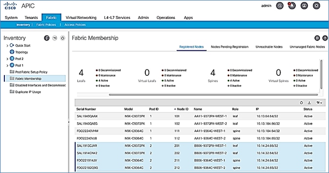
5. Confirm that the status is Active for all Leaf and Spine switches in Pod-2. For this CVD, the new APIC will be dual-homed to both Leaf switches in Pod-2.
Initial Setup of Pod-2 APIC
Follow the procedures outlined in this section to do an initial setup and configuration of the third APIC in the APIC cluster that will manage the ACI fabric. In this design, two APICs are deployed in Pod-1 and a third APIC in Pod-2.
Prerequisites
KVM Console access is necessary to do an initial setup and configuration of a new APIC. KVM access is available through CIMC Management and therefore access to CIMC Management on the APIC server is required.
Setup Information
The initial setup of APIC in Pod-2 requires the information provided in this section.
· CIMC Management IP Addresses
· CIMC login credentials for the APIC being setup
![]() The TEP Address Pool is the APIC TEP pool and should be the same for all APICs in a cluster regardless of their location.
The TEP Address Pool is the APIC TEP pool and should be the same for all APICs in a cluster regardless of their location.
![]() BD Multicast Address (GIPO) is configured only once, during the initial setup of APIC-1. APIC-1 refers to the first controller in the cluster. The remaining controllers and switches sync to the configuration on APIC-1.
BD Multicast Address (GIPO) is configured only once, during the initial setup of APIC-1. APIC-1 refers to the first controller in the cluster. The remaining controllers and switches sync to the configuration on APIC-1.
![]() The APIC username and password is configured only once, during the initial setup of APIC-1 or the first controller in the cluster. The remaining controllers and switches sync to the configuration on APIC-1.
The APIC username and password is configured only once, during the initial setup of APIC-1 or the first controller in the cluster. The remaining controllers and switches sync to the configuration on APIC-1.
Table 26 Setup Parameters for Pod-2 APIC
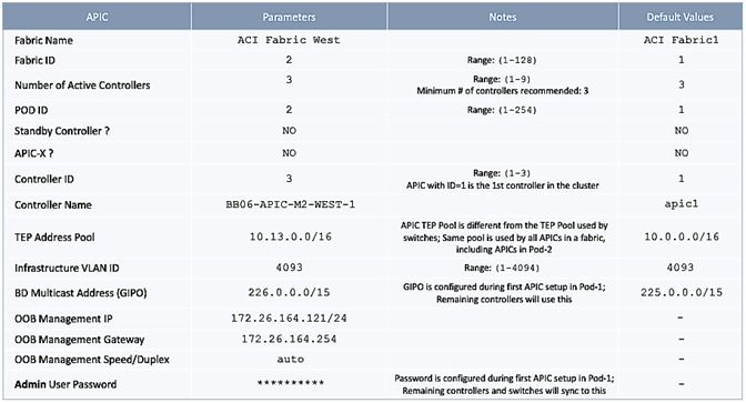
Deployment Steps
To setup a new APIC in Pod-2, follow these steps:
1. Use a browser to navigate to the CIMC IP address of the new APIC. Log in using admin account.
2. From the top menu, click Launch KVM. Select HTML based KVM from the drop-down list.
3. When the KVM Application launches, the initial APIC setup screen should be visible. Press any key to start the Setup Utility. Use the Setup information provided above to step through the initial APIC configuration as shown below.
![]() If the APIC was previously configured, reset it to factory defaults and wipe it clean before proceeding.
If the APIC was previously configured, reset it to factory defaults and wipe it clean before proceeding.
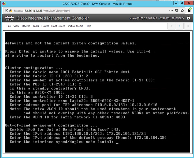
4. Press Enter to accept [auto] as the default for the last question.
5. Review the configured information.
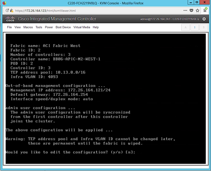
6. Click y if necessary to go back and make changes, otherwise press Enter to accept the configuration.
Verify Pod-2 APIC is Part of the APIC Cluster
To confirm that the Pod-2 APIC was successfully added to the APIC cluster, follow these steps:
1. Use a browser to navigate to the APIC GUI. Log in using admin account.
2. From the top menu, select System > Controllers.
3. From the left navigation pane, navigate to Controllers.
4. From the left navigation pane, select and expand one of the Pod-1 APICs. Navigate to Cluster as Seen by Node.
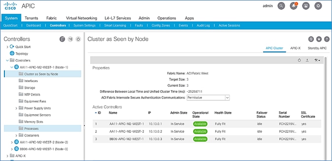
5. Verify that the newly deployed Pod-2 APIC is In Service, Available and Fully Fit as shown above.
6. Note the TEP IP Address of the newly deployed APIC (for example, 10.13.0.3). This address will be used to configure DHCP Relay on IPN routers to point to the new APIC. For Pod-1 APICs, DHCP relay was configured as a part of the initial IPN configuration.
Add Pod-2 APIC as DHCP Relay Destination
In this section, DHCP Relay is configured on the IPN routers to point to the newly deployed APIC. DHCP Relay should be configured for all APICs in the cluster.
Setup Information
· Pod-2 APIC TEP IP Address: 10.13.0.3
Use the above information to configure DHCP relay on IPN routers to point to the newly deployed APIC in Pod-2.
Configure DHCP Relay for New APIC on IPN Devices in Pod-1
| POD-1: IPN Router#1 |
POD-1: IPN Router#2 |
|
...
interface Ethernet1/49 description To POD-1:AA11-9364C-1:E1/47 no switchport mtu 9216 no shutdown
interface Ethernet1/49.4 mtu 9216 encapsulation dot1q 4 vrf member MultiPod-Fabric-West ip address 10.113.11.2/30 ip ospf network point-to-point ip ospf mtu-ignore ip router ospf 10 area 0.0.0.0 ip pim sparse-mode ip dhcp relay address 10.13.0.1 ip dhcp relay address 10.13.0.2 ip dhcp relay address 10.13.0.3 no shutdown
interface Ethernet1/50 description To POD-1:AA11-9364C-2:E1/47 no switchport mtu 9216 no shutdown
interface Ethernet1/50.4 mtu 9216 encapsulation dot1q 4 vrf member MultiPod-Fabric-West ip address 10.113.12.2/30 ip ospf network point-to-point ip ospf mtu-ignore ip router ospf 10 area 0.0.0.0 ip pim sparse-mode ip dhcp relay address 10.13.0.1 ip dhcp relay address 10.13.0.2 ip dhcp relay address 10.13.0.3 no shutdown |
...
interface Ethernet1/49 description To POD-1:AA11-9364C-WEST-1:E1/48 no switchport mtu 9216 no shutdown
interface Ethernet1/49.4 mtu 9216 encapsulation dot1q 4 vrf member MultiPod-Fabric-West ip address 10.113.11.6/30 ip ospf network point-to-point ip ospf mtu-ignore ip router ospf 10 area 0.0.0.0 ip pim sparse-mode ip dhcp relay address 10.13.0.1 ip dhcp relay address 10.13.0.2 ip dhcp relay address 10.13.0.3 no shutdown
interface Ethernet1/50 description To POD-1:AA11-9364C-WEST-2:E1/48 no switchport mtu 9216 no shutdown
interface Ethernet1/50.4 mtu 9216 encapsulation dot1q 4 vrf member MultiPod-Fabric-West ip address 10.113.12.6/30 ip ospf network point-to-point ip ospf mtu-ignore ip router ospf 10 area 0.0.0.0 ip pim sparse-mode ip dhcp relay address 10.13.0.1 ip dhcp relay address 10.13.0.2 ip dhcp relay address 10.13.0.3 no shutdown
|
Configure DHCP Relay for New APIC on IPN Devices in Pod-2
| POD-2: IPN Router#1 |
POD-2: IPN Router#2 |
|
…
interface Ethernet1/49 description To POD-2:BB06-9364C-1:E1/47 no switchport mtu 9216 no shutdown
interface Ethernet1/49.4 mtu 9216 encapsulation dot1q 4 vrf member MultiPod-Fabric-West ip address 10.114.11.2/30 ip ospf network point-to-point ip ospf mtu-ignore ip router ospf 10 area 0.0.0.0 ip pim sparse-mode ip dhcp relay address 10.13.0.1 ip dhcp relay address 10.13.0.2 ip dhcp relay address 10.13.0.3 no shutdown
interface Ethernet1/50 description To POD-2:BB06-9364C-2:E1/48 no switchport mtu 9216 no shutdown
interface Ethernet1/50.4 mtu 9216 encapsulation dot1q 4 vrf member MultiPod-Fabric-West ip address 10.114.12.2/30 ip ospf network point-to-point ip ospf mtu-ignore ip router ospf 10 area 0.0.0.0 ip pim sparse-mode ip dhcp relay address 10.13.0.1 ip dhcp relay address 10.13.0.2 ip dhcp relay address 10.13.0.3 no shutdown
|
...
interface Ethernet1/49 description To POD-2:BB06-9364C-WEST-1:E1/48 no switchport mtu 9216 no shutdown
interface Ethernet1/49.4 mtu 9216 encapsulation dot1q 4 vrf member MultiPod-Fabric-West ip address 10.114.11.6/30 ip ospf network point-to-point ip ospf mtu-ignore ip router ospf 10 area 0.0.0.0 ip pim sparse-mode ip dhcp relay address 10.13.0.1 ip dhcp relay address 10.13.0.2 ip dhcp relay address 10.13.0.3 no shutdown
interface Ethernet1/50 description To POD-2:BB06-9364C-WEST-2:E1/48 no switchport mtu 9216 no shutdown
interface Ethernet1/50.4 mtu 9216 encapsulation dot1q 4 vrf member MultiPod-Fabric-West ip address 10.114.12.6/30 ip ospf network point-to-point ip ospf mtu-ignore ip router ospf 10 area 0.0.0.0 ip pim sparse-mode ip dhcp relay address 10.13.0.1 ip dhcp relay address 10.13.0.2 ip dhcp relay address 10.13.0.3 no shutdown
|
Verify ACI Multi-Pod Fabric Setup
This section provides a few GUI and CLI commands that can be used to verify that the protocols are working correctly before proceeding to the next stage of the deployment.
Verify OSPF Status on Spine Switches
OSPF is running between Spine switches and IPN devices in each Pod. To verify that OSPF is setup and working correctly between Pods, follow these steps:
1. Use a browser to navigate to the APIC GUI. Log in using admin account.
2. From the top menu, select Fabric > Inventory.
3. From the left navigation pane, select and expand Inventory > Pod 1 > (Name_of_Spine_switch_in_Pod_1) > Protocols > OSPF > OSPF for VRF-overlay-1.
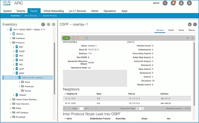
4. In the right window pane, under the General tab, the top left icon indicates the Health for OSPF in VRF overlay-1. Confirm that the OSPF health is at 100 indicating there are no faults or errors for OSPF. Navigate to the Neighbors section and confirm for each IPN neighbor in the same Pod, neighbor state is Up and the OSPF State is Full.
5. Repeat steps 1-4 to verify OSPF on other Spine switches in the Pod that connect to the IPN.
6. You can also verify that OSPF is setup correctly by executing the following commands from CLI. SSH into the Spine switches and log in using the admin account:
- show ip ospf neighbors vrf overlay-1
- show ip ospf route vrf overlay-1
- show ip route vrf overlay-1
Verify MP-BGP EVPN Status on Spine Switches
MP-BGP sessions run between Spine switches in each Pod that connect to the IPN. To verify that MP-BGP EVPN is setup and working correctly between Pods, follow these steps:
1. Use a browser to navigate to the APIC GUI. Log in using admin account.
2. From the top menu, select Fabric > Inventory.
3. From the left navigation pane, select and expand Inventory > Pod 1 > (Name_of_Spine_switch_in_Pod_1) > Protocols > BGP > BGP for VRF-overlay-1 > Neighbors.
4. In the right window pane, select and expand the router ID (for example, 14.14.14.11) for the peer Spines in Pod-2.
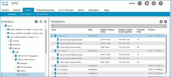
5. Verify that the State is Established and for L2Vpn EVpn address family, paths are being learned. Also confirm that the BGP health is at 100 indicating there are no faults or errors for BGP in VRF overlay-1 by navigating back to BGP for VRF-overlay-1 in the left navigation pane.
6. Repeat steps 1-5 to verify BGP on other Spine switches in the Pod that connect to the IPN.
7. You can also verify that MP-BGP EVPN is setup correctly by executing the following commands from CLI. SSH into the Spine switches and log in using the admin account.
- show bgp l2vpn evpn summary vrf overlay-1
Verify COOP Status on Spine Switches
Council of Oracles Protocol (COOP) database maintained on Spines in each Pod, is a database of all endpoints learned. This includes endpoints learned from within the Pod as well as the addresses learned through the tunnel between spine switches in different pods. The ETEP used by MP-BGP EVPN will be used by COOP to identify a remote pod's set of anycast addresses.
To verify that COOP database is learning addresses from the remote Pod, follow these steps:
1. Use a browser to navigate to the APIC GUI. Log in using admin account.
2. From the top menu, select Fabric > Inventory.
3. From the left navigation pane, select and expand Inventory > Pod 1 > (Name_of_Spine_switch_in_Pod_1) > Protocols > COOP > COOP for VRF-overlay-1.
4. In the right window pane, under the General tab, the top left icon indicates the Health for COOP in VRF overlay-1. Confirm that the COOP health is at 100 indicating there are no faults or errors.
5. From the left navigation pane, select and expand Inventory > Pod 1 > (Name_of_Spine_switch_in_Pod_1) > Protocols > COOP > COOP for VRF-overlay-1 > Endpoint Database.
6. In the right window pane, verify that endpoints from Pod-2 are being learned (for example, 10.1.167.168).
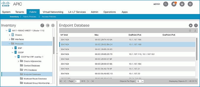
7. Double-click one endpoint to get additional details. Note that the Publisher ID is the ETEP address (for example, 10.114.114.1) of a Spine in Pod-2.
8. Repeat steps 1-7 to verify COOP on other Spine switches in the Pod that connect to the IPN.
9. You can also verify that COOP is functioning correctly by executing the following commands from CLI. SSH into the Spine switches and log in using the admin account.
- show coop internal info ip-db
Deploy Shared Layer 3 Connectivity to Outside – Pod-2
Complete the steps outlined in this section to establish Layer 3 connectivity or a Shared L3Out from Pod-2 to networks outside the ACI fabric.
Deployment Overview
The Shared L3Out connection is established in the system-defined common Tenant as a common resource that can be shared by multiple tenants in the ACI fabric. In this design, the Shared L3out design in Pod-2 is same as that of Pod-1. For additional details, see the Shared L3Out deployment section for Pod-1. Some specifics of the Pod-2 deployment are summarized below:
· Pair of Border Leaf switches in Pod-2 connect to a pair of Nexus 7000 routers outside the ACI fabric using 4 x 10GbE links. Nexus 7000 routers serve as a gateway to the networks outside the fabric.
· Routing protocol use to exchange routes between the ACI fabric and networks outside ACI is OSPF
· VLAN tagging is used for connectivity across the 4 links – a total of 4 VLANs for the 4 x 10GbE links. VLANs are configured on separate sub-interfaces.
· Fabric Access Policies are configured on ACI Leaf switches to connect to the External Routed domain using VLAN pool (vlans: 315-318).
· Pod-2 uses the same Tenant (common), VRF (common-SharedL3Out_VRF) and Bridge Domain (common-SharedL3Out_BD) as Pod-1 for Shared L3Out.
· The shared L3Out created in common Tenant “provides” an external connectivity contract that can be “consumed” from any tenant.
· The Nexus 7000s connected to Pod-2 are configured to originate and send a default route via OSPF to the border leaf switches in Pod-2.
· ACI leaf switches in Pod-2 advertise tenant subnets back to Nexus 7000 switches.
· In ACI 4.0, ACI leaf switches can also advertise host-routes if it is enabled.
Create VLAN Pool for External Routed Domain
In this section, a VLAN pool is created to enable connectivity to the external networks, outside the ACI fabric. The VLANs in the pool are for the four links that connect ACI Border Leaf switches to the Nexus Gateway routers in the non-ACI portion of the customer’s network.
Table 27 VLAN Pool for Shared L3Out in Pod-2
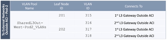
To configure a VLAN pool to connect to external gateway routers outside the ACI fabric, follow these steps:
1. Use a browser to navigate to the APIC GUI. Log in using the admin account.
2. From the top navigation menu, select Fabric > Access Policies.
3. From the left navigation pane, expand and select Pools > VLAN.
4. Right-click and select Create VLAN Pool.
5. In the Create VLAN Pool pop-up window, specify a Name (for example, SharedL3Out-West-Pod2_VLANs) and for Allocation Mode, select Static Allocation.
6. For Encap Blocks, use the [+] button on the right to add VLANs to the VLAN Pool. In the Create Ranges pop-up window, configure the VLANs that need to be configured from the Border Leaf switches to the external gateways outside the ACI fabric. Leave the remaining parameters as-is.
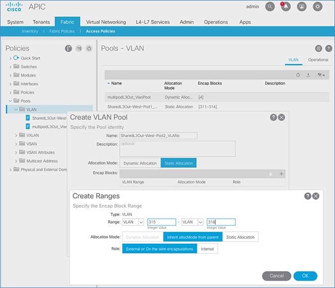
7. Click OK. Use the same VLAN ranges on the external gateway routers to connect to the ACI Fabric.
8. Click Submit to complete.
Configure Domain Type for External Routed Domain
Table 28 Domain Type for Shared L3Out in Pod-2
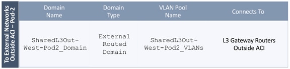
To specify the domain type to connect to external gateway routers outside the ACI fabric, follow these steps:
1. Use a browser to navigate to the APIC GUI. Log in using the admin account.
2. From the top navigation menu, select Fabric > Access Policies.
3. From the left navigation pane, expand and select Physical and External Domains > External Routed Domains.
4. Right-click External Routed Domains and select Create Layer 3 Domain.
5. In the Create Layer 3 Domain pop-up window, specify a Name for the domain. For the VLAN Pool, select the previously created VLAN Pool from the drop-down list.
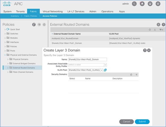
6. Click Submit to complete.
Create Attachable Access Entity Profile for External Routed Domain
Table 29 Attachable Access Entity Profile (AAEP) for Shared L3Out in Pod-2
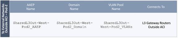
To create an Attachable Access Entity Profile (AAEP) to connect to external gateway routers outside the ACI fabric, follow these steps:
1. Use a browser to navigate to the APIC GUI. Log in using the admin account.
2. From the top navigation menu, select Fabric > Access Policies.
3. From the left navigation pane, expand and select Policies > Global > Attachable Access Entity Profiles.
4. Right-click and select Create Attachable Access Entity Profile.
5. In the Create Attachable Access Entity Profile pop-up window, specify a Name (for example, SharedL3Out-West-Pod2_AAEP).
6. For the Domains, click the [+] on the right-side of the window and select the previously created domain from the drop-down list below Domain Profile.
7. Click Update.
You should now see the selected domain and the associated VLAN Pool as shown below:
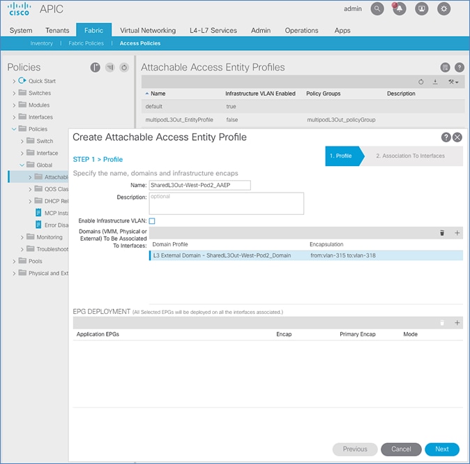
8. Click Next. This profile is not associated with any interfaces at this time. They can be associated once the interfaces are configured in an upcoming section.
9. Click Finish to complete.
Configure Interfaces to External Routed Domain
Border Leaf switches (Node ID: 201,202) in Pod-2 connect to External Gateways (Nexus 7000 series switches) using 10Gbps links, on ports 1/47 and 1/48.
Figure 27 Fabric Access Policies for Shared L3Out in Pod-2
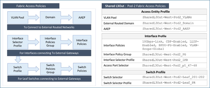
Create Interface Policy Group for Interfaces to External Routed Domain
To create an interface policy group to connect to external gateways outside the ACI fabric, follow these steps:
1. Use a browser to navigate to the APIC GUI. Log in using the admin account.
2. From the top navigation menu, select Fabric > Access Policies.
3. From the left navigation pane, expand and select Interfaces > Leaf Interfaces > Policy Groups > Leaf Access Port.
4. Right-click and select Create Leaf Access Port Policy Group.
5. In the Create Leaf Access Port Policy Group pop-up window, specify a Name and select the applicable interface policies from the drop-down list for each field.
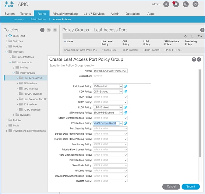
6. For the Attached Entity Profile, select the previously created AAEP to external routed domain.
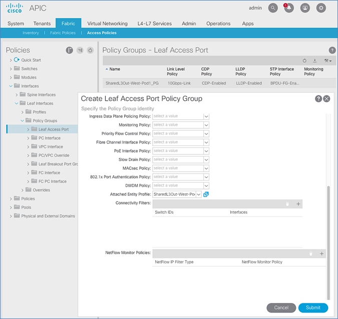
7. Click Submit to complete.
You should now see the policy groups for both Pods as shown below:
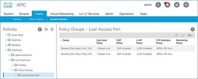
Create Interface Profile for Interfaces to External Routed Domain
To create an interface profile to connect to external gateways outside the ACI fabric, follow these steps:
1. Use a browser to navigate to the APIC GUI. Log in using the admin account.
2. From the top navigation menu, select Fabric > Access Policies.
3. From the left navigation menu, expand and select Interfaces > Leaf Interfaces > Profiles.
4. Right-click and select Create Leaf Interface Profile.
5. In the Create Leaf Interface Profile pop-up window, specify a Name . For Interface Selectors, click the [+] to select access ports to apply interface policies to. In this case, the interfaces are access ports that connect Border Leaf switches to gateways outside ACI.
6. In the Create Access Port Selector pop-up window, specify a selector Name. For the Interface IDs, specify the access ports connecting to the two external gateways. For the Interface Policy Group, select the previously created Policy Group from the drop-down list.
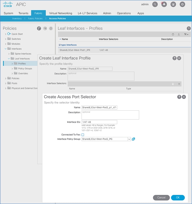
7. Click OK to complete and close the Create Access Port Selector pop-up window.
8. Click Submit to complete and close the Create Leaf Interface Profile pop-up window.
You should now see the Interface profiles for both Pods as shown below:
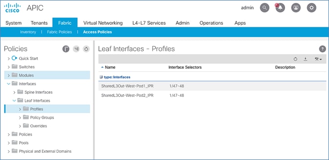
Create Leaf Switch Profile to External Routed Domain
To create a leaf switch profile to configure connectivity to external gateway routers outside the ACI fabric, follow these steps:
1. Use a browser to navigate to the APIC GUI. Log in using the admin account.
2. From the top navigation menu, select Fabric > Access Policies.
3. From the left navigation menu, expand and select Switches > Leaf Switches > Profiles.
4. Right-click and select Create Leaf Profile.
5. In the Create Leaf Profile pop-up window, specify a profile Name. For Leaf Selectors, click the [+] to select the Leaf switches to apply the policies to. In this case, the Leaf switches are the Border Leaf switches that connect to the gateways outside ACI.
6. Specify a Leaf Selector Name. For the Interface IDs, specify the access ports connecting to the two external gateways. For Blocks, select the Node IDs of the Border Leaf switches from the drop-down list. Click Update.
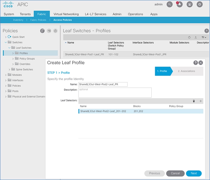
7. Click Next.
8. In the Associations window, select the previously created Interface Selector Profiles from the list.
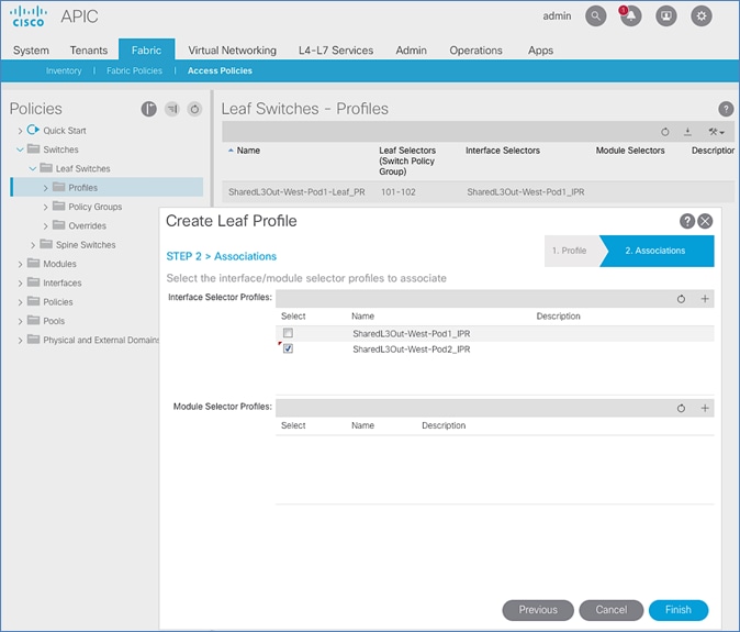
9. Click Finish to complete.
You should now see the profiles for both Pods as shown below:
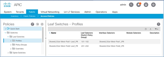
Configure Tenant Networking for Shared L3Out
Pod-2 uses the same Tenant , VRF and Bridge Domain as Pod-1 for Shared L3Out. No additional configuration is therefore necessary to enable Tenant Networking in Pod-2. Table 30 lists the Tenant networking for Shared L3Out that was configured during Pod-1 setup.
Table 30 Tenant Networking for Shared L3Out
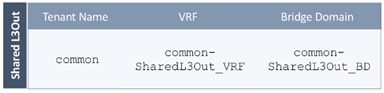
Configure External Routed Networks under Tenant Common
Table 31 Routed Outside – Pod-1
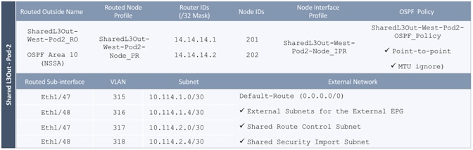
To specify the domain type to connect to external gateway routers outside the ACI fabric, follow these steps:
1. Use a browser to navigate to the APIC GUI. Log in using the admin account.
2. From the top navigation menu, select Tenants > common.
3. In the left navigation pane, select and expand Tenant common > Networking > External Routed Networks.
4. Right-click and select Create Routed Outside.
5. In the Create Routed Outside pop-up window, specify a Name (for example, SharedL3Out-West-Pod2_RO). Select the check box next to OSPF. For the OSPF Area ID, enter 0.0.0.10 (should match the external gateway configuration). For the VRF, select the previously created VRF from the drop-down list. For the External Routed Domain, select the previously created domain from the drop-down list. For Nodes and Interfaces Protocol Profiles, click [+] to add a Node Profile.
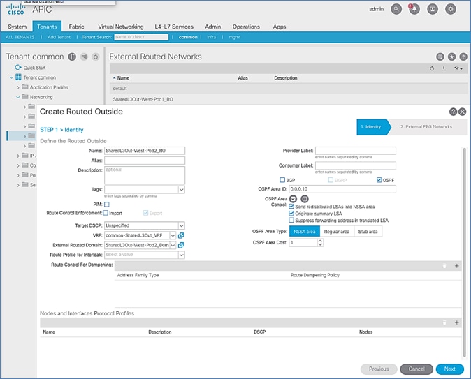
6. In the Create Node Profile pop-up window, specify a profile Name (for example, SharedL3Out-West-Pod2-Node_PR). For Nodes, click [+] to add a Node.
7. In the Select Node pop-up window, for the Node ID, select first Border Leaf switch from the drop-down list. For the Router ID, specify the router ID for the first Border Leaf Switch (for example, 14.14.14.1). Click OK to complete selecting the Node. Repeat to add the second Border Leaf to the list of Nodes. For OSPF Interface Profiles, click [+] to add a profile.
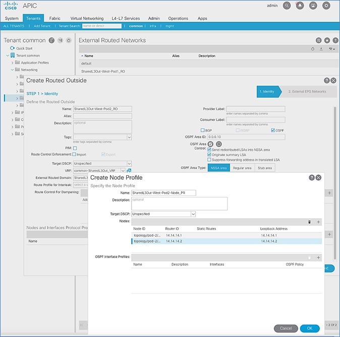
8. In the Create Interface Profile pop-up window, for Step 1 > Identity, specify a Name (for example, SharedL3Out-West-Pod2-Node_IPR). Click Next. In Step 2 > Protocol Profiles, for the OSPF Policy, use the drop-down list to select Create OSPF Interface Policy.
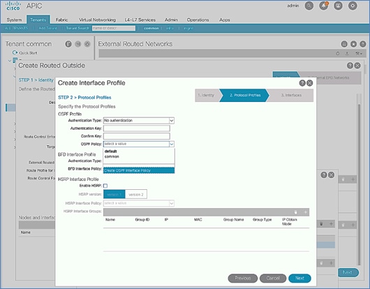
9. In the Create OSPF Interface Policy pop-up window, specify a Name (for example, SharedL3Out-West-Pod2-OSPF_Policy). For Network Type, select Point-to-Point. For Interface Controls, select the checkbox for MTU ignore.
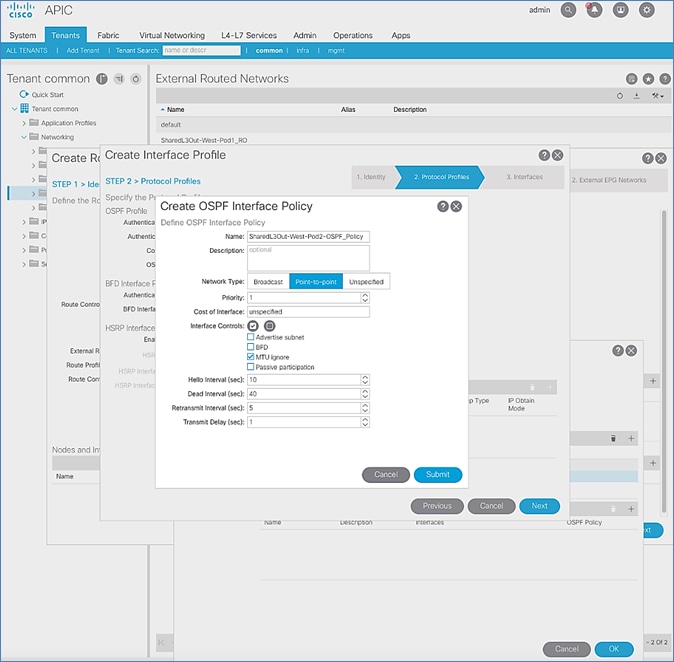
10. Click Submit to complete creating the OSPF policy.
11. In the Create Interface Profile pop-up window, for the OSPF Policy, the newly created policy should now show up as the policy.
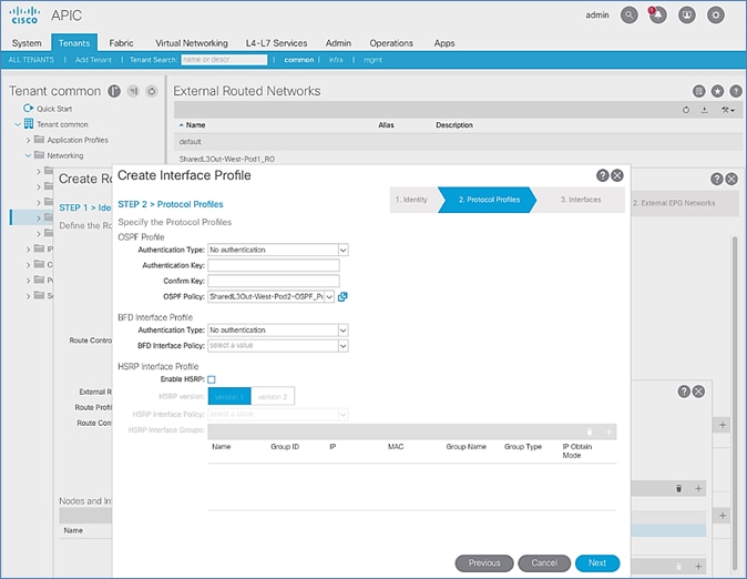
12. Click Next.
13. For STEP 3 > Interfaces, select the tab for Routed Sub-Interface. Click [+] on the right side of the window to add a routed sub-interface.
14. In the Select Routed Sub-Interface pop-up window, for Node, select the first Border Leaf. For Path, select the interface (for example, 1/47) on the first Border Leaf that connects to the first external gateway. For Encap, specify the VLAN (for example, 315). For IPv4 Primary / IPv6 Preferred Address, specify the address (for example, 10.114.1.1/30).
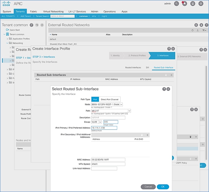
15. Click OK to complete configuring the first routed sub-interface.
16. In STEP 3 > Interfaces, under Routed Sub-Interface tab, click [+] again to create the next sub-interface that connects the first Border Leaf to the second Gateway.
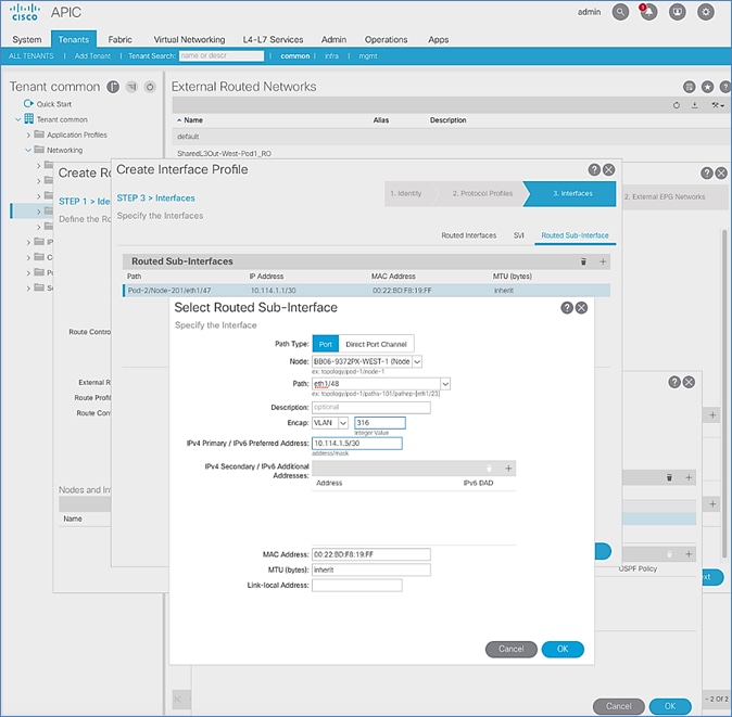
17. Click OK to complete configuring the first routed sub-interface.
18. Repeat steps 1-17 to create two more sub-interfaces on the second Border Leaf switch to connect to the two external gateways.
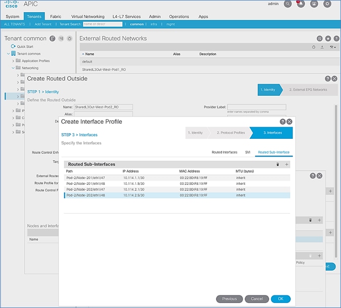
19. Click OK to complete the Interface Profile configuration and to close the Create Interface Profile pop-up window.
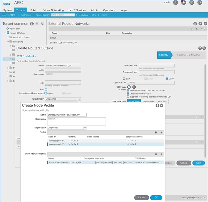
20. Click OK to complete the Node Profile configuration and to close the Create Node Profile pop-up window.
21. In the Create Routed Outside pop-up window, click Next. In STEP 2 > External EPG Networks, for External EPG Networks, click [+] to add an external network.
22. In the Created External Network pop-up window, specify a Name (for example, Default-Route). For Subnet, click [+] to add a Subnet.
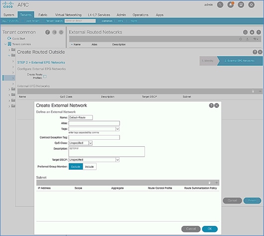
23. In the Create Subnet pop-up window, for the IP Address, enter a route (for example, 0.0.0.0/0). Select the checkboxes for External Subnets for the External EPG, Shared Route Control Subnet, and Shared Security Import Subnet.
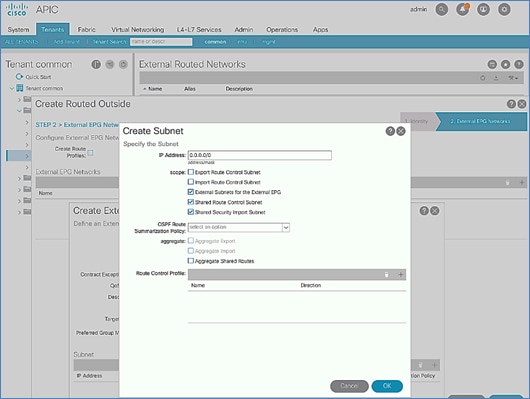
24. Click OK to complete creating the subnet and close the Create Subnet pop-up window.
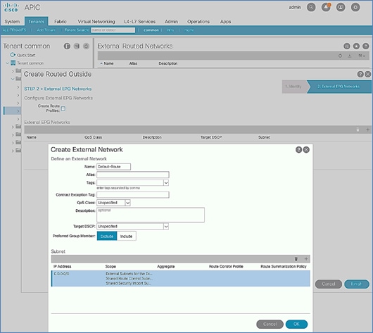
25. Click OK again to complete creating the external network and close the Create External Network pop-up window.
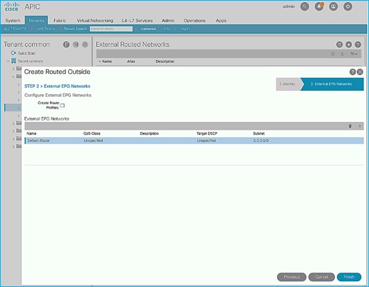
26. Click Finish to complete creating the Routed Outside.
Create Contracts for External Routed Networks from Tenant (common)
Table 32 Contracts for External Routed Networks
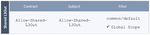
To create contracts for external routed networks from Tenant common, follow these steps:
1. Use a browser to navigate to the APIC GUI. Log in using the admin account.
2. From the top navigation menu, select Tenants > common.
3. In the left navigation pane, select and expand Tenant common > Contracts.
4. Right-click Contracts and select Create Contract.
5. In the Create Contract pop-up window, specify a Name (for example, Allow-Shared-L3Out).
6. For Scope, select Global from the drop-down list to allow the contract to be consumed by all tenants.
7. For Subjects, click [+] on the right side to add a contract subject.
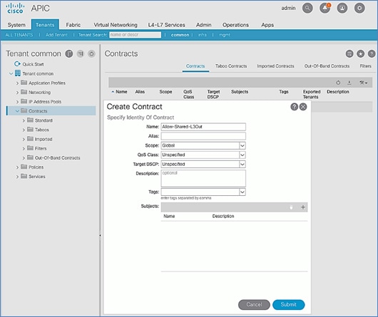
8. In the Create Contract Subject pop-up window, specify a Name (for example, Allow-Shared-L3Out).
9. For Filters, click [+] on the right side to add a filter.
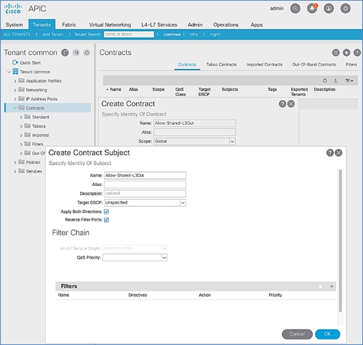
10. In the Filters section of the window, for Name, select default (common) from the drop-down list to create a default filter for Tenant common.
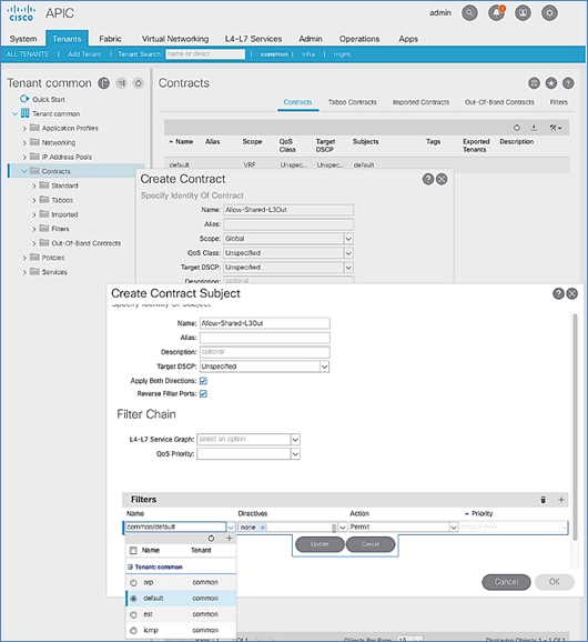
11. Click Update.
12. Click OK to complete creating the contract subject.
13. Click Submit to complete creating the contract.
Provide Contracts for External Routed Networks from Tenant (common)
Table 33 Contracts for External Routed Networks
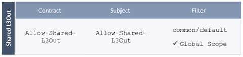
To provide contracts for external routed networks from Tenant common, follow these steps:
1. Use a browser to navigate to the APIC GUI. Log in using the admin account.
2. From the top navigation menu, select Tenants > common.
3. In the left navigation pane, select and expand Tenant common > Networking > External Routed Networks.
4. Select and expand the recently created External Routed Network for SharedL3out or Routed Outside network (for example, SharedL3Out-West-Pod1_RO).
5. Select and expand Networks.
6. Select the recently created route (for example, Default-Route).
7. In the right window pane, select the tab for Policy and then Contracts.
8. Under the Provided Contracts tab, click [+] on the right to add a Provided Contract.
9. For Name, select the previously created contract (for example, common/Allow-Shared-L3Out) from the drop-down list.
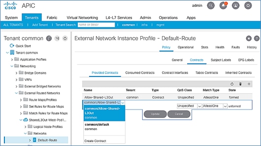
10. Click Update.
11. Other Tenants can now ‘consume’ the Allow-Shared-L3Out contract to route traffic outside the ACI fabric. This deployment example shows a default filter to allow all traffic. More restrictive contracts can be created for a more restrictive access to destinations outside the fabric.
Configure External Gateways in the Outside Network
This section provides a sample configuration from the Nexus switches that serve as external Layer 3 Gateways for Pod-2. The gateways are in the external network and peer with ACI border leaf switches in Pod-2 using OSPF. The gateway configuration shown below shows only the relevant portion of the configuration – it is not the complete configuration .
Enable Protocols
The protocols used between the ACI border leaf switches and external gateways have to be explicitly enabled on Nexus platforms used as external gateways in this design. The configuration to enable these protocols are provided below:
Table 34 External Gateways for Pod-2 – Protocols
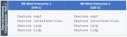
Configure OSPF
OSPF is used between the external gateways and ACI border leaf switches to exchange routing between the two domains. The global configuration for OSPF is provided below. Loopback is used as the router IDs for OSPF. Note that interfaces between ACI border leaf switches will be in OSPF Area 10.
Table 35 External Gateways for Pod-2 – Protocols
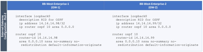
Configure Interfaces
The interface level configuration for connectivity between external gateways and ACI border leaf switches is provided below. Note that interfaces between ACI border leaf switches are in OSPF Area 10 while the loopbacks and port-channel links between the gateways are in OSPF Area 0.
Table 36 Interface Configuration – To ACI Border Leaf Switches
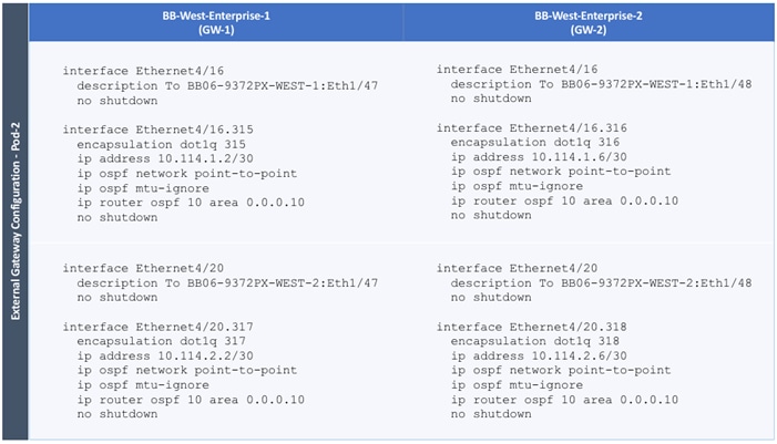
The configuration on the port-channel with 2x10GbE links that provide direct connectivity between the external gateways is provided below.
Table 37 Interface Configuration – Between External Gateways
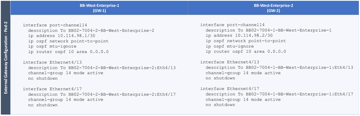
Pod-2 Configuration Completion
The DC2 93180YC-FX leaf switches will be added using the Cisco ACI Fabric Discovery steps found in the DC1 Deployment Guide: https://www.cisco.com/c/en/us/td/docs/unified_computing/ucs/UCS_CVDs/cisco_hitachi_adaptivesolutions_ci_ssaci.html#_Toc19636179
The verification and policy setup steps following the leaf switch discovery can be ignored, and the DC2 completion of Pod-2 setup can continue from the DC1 Deployment Guide beginning at the vPC creation process for any external management switches used in DC2: https://www.cisco.com/c/en/us/td/docs/unified_computing/ucs/UCS_CVDs/cisco_hitachi_adaptivesolutions_ci_ssaci.html#_Toc19636195
Changes for this remaining Pod-2 deployment are for the following sections:
· Create Virtual Port Channels (vPCs)
- vPC – Management Switch
Table 11 Site1-IB-Mgmt <119>, will be DC2-IB <219>
The VPC Domain Id for the example leaf pair will be a unique number for a newly deployed leaf.
- vPC – Cisco UCS Fabric Interconnects
Table 12 Site1-Infra <119>, will be DC2-IB <219>
Cisco MDS Deployment
The Cisco MDS deployment for DC2 is configured with the same steps outlined in the DC1 Deployment Guide here: https://www.cisco.com/c/en/us/td/docs/unified_computing/ucs/UCS_CVDs/cisco_hitachi_adaptivesolutions_ci_ssaci.html#_Toc19636216
The zoning and device aliases can be implemented by the same DCNM instance if one has been utilized. When using DCNM, the established device-aliases, zones and zonesets will become active once the Cross Site ISL is activated between switches.
Figure 28 MDS ISL connections between datacenters
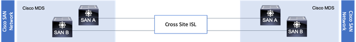
The Inter-Switch Links (ISL) were created by connecting the corresponding switch ports of the SAN A and SAN B MDS switches of each site to each other and enabling these ports within the vsan database for the appropriate VSANs. Ports shown below in example are 1/15 and 1/16 on each switch, and VSAN 101 is used for fabric A and VSAN 102 is used for fabric B:
Cisco MDS 9706 A
aa19-9706-1(config)# vsan database
aa19-9706-1(config-vsan-db)# vsan 101 interface fc1/15
aa19-9706-1(config-vsan-db)# vsan 101 interface fc1/16
Cisco MDS 9706 B
aa19-9706-2(config)# vsan database
aa19-9706-2(config-vsan-db)# vsan 102 interface fc1/15
aa19-9706-2(config-vsan-db)# vsan 102 interface fc1/16
Cisco MDS 9148T A
bb22-9148-1(config)# vsan database
bb22-9148-1 (config-vsan-db)# vsan 101 interface fc1/15
bb22-9148-1 (config-vsan-db)# vsan 101 interface fc1/16
Cisco MDS 9148T B
bb22-9148-2(config)# vsan database
bb22-9148-2 (config-vsan-db)# vsan 102 interface fc1/15
bb22-9148-2 (config-vsan-db)# vsan 102 interface fc1/16
To configure these ISL connections for greater resiliency, they can be bundled into SAN Port Channels. Example of the steps required to run on each switch below (vsan appropriate to the SAN fabric should be specified):
AA19-9706-1(config)# int port-channel 115
AA19-9706-1(config-if) # switchport rate-mode dedicated
AA19-9706-1(config-if) # vsan database
AA19-9706-1(config-vsan-db)# vsan 101 interface port-channel 115
AA19-9706-1(config-vsan-db)# int fc1/15-16
AA19-9706-1(config-if)# channel-group 115 force
AA19-9706-1(config-if)# no shut
The fibre channel connections between these datacenter switches did not implement any distance simulation during the validation, and instead are relying on the established validations of specific long reach fibre channel options within Cisco. These options include specific fibre channel transceivers as well as FCIP switch options within the MDS family of products.
Supported Transceivers for long distance options: https://www.cisco.com/c/en/us/products/collateral/storage-networking/mds-9000-series-multilayer-switches/product_data_sheet09186a00801bc698.html
MDS 9700 Series SAN Extension Module: https://www.cisco.com/c/en/us/products/collateral/storage-networking/mds-9700-series-multilayer-directors/datasheet-c78-737857.html
MDS 9250i Multiservice Switch: https://www.cisco.com/c/en/us/products/collateral/storage-networking/mds-9250i-multiservice-fabric-switch/data_sheet_c78-727493.html
Cisco UCS Deployment
The Cisco UCS deployment will follow the basic steps of the DC1 Deployment Guide beginning at: https://www.cisco.com/c/en/us/td/docs/unified_computing/ucs/UCS_CVDs/cisco_hitachi_adaptivesolutions_ci_ssaci.html#_Toc19636226
These steps will create the same Service Profile Templates, and the remaining DC1 Deployment Guide will need to be stepped through to allocate FC boot LUNs and zoning on the DC2 MDS as needed.
The following information needs to be noted when setting up the DC2 UCS Domain:
· DC2-IB VLAN will need to be added instead of Site-Infra as a VLAN of the LAN Cloud within UCS
· DC2-IB will need to be included in the vNIC_Mgmt_A and vNIC_Mgmt_B vNIC Templates
· The SAN Targets configured for the Boot Policy used by the Service Profile Template will need to be configured for the appropriate VSP WWN targets
Cisco UCS Manager Integration
With Cisco UCS in DC2 configured, a return to the APIC is need to configure the Cisco UCS Manager Integration with ACI to allow the VMM to trigger changes within the DC2 FIs.
Before beginning the configuration, the Cisco-ExternalSwitch can be downloaded and upgraded to 1.1 for this deployment from:
https://dcappcenter.cisco.com/externalswitch.html
For the Cisco UCS Integration to cover the DC2 UCS domain, an adjustment will need to occur to the DC1 Attachable Access Entity Profile (AEP) that was created during the creation of the DC1 UCS vPC and is associated with the name used for the External Bridge Domain specified for the UCS vPC. The example name given to in the DC1 Deployment Guide External Bridge Domain was CHV-Site1-UCS, which created an AEP with the name of CHV-Site1-UCS_AttEntityP.
This adjustment is needed because the VMM used for integrating with the vCenter is only associated with one AEP through the APIC.
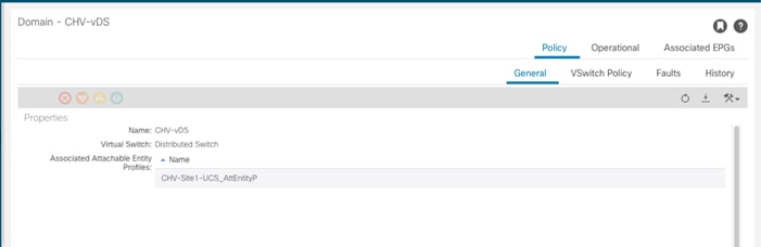
To make this adjustment, follow these steps:
1. Open the AEP for CHV-Site1-UCS_AttEntityP within the APIC:
Fabric > Access Policies > Policies > Global > Attachable Access Entity Profiles
2. Click the + icon on the Domains line to add the L2 External Bridge Domain associated with the DC2 UCS vPC.
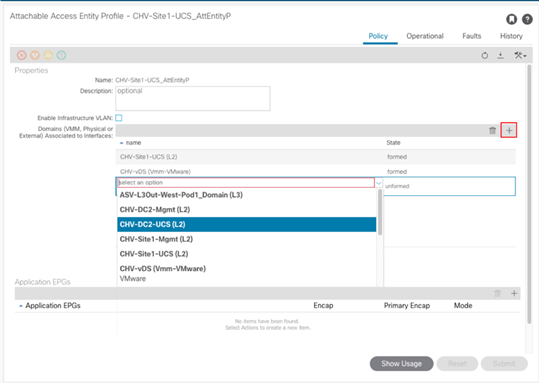
3. Click Update.
The Cisco UCS Manager Integration section is here: https://www.cisco.com/c/en/us/td/docs/unified_computing/ucs/UCS_CVDs/cisco_hitachi_adaptivesolutions_ci_ssaci.html#_Toc19636290 and go to section “Create and Configure an Integration Group” for the DC2 UCSM. Within this section the following requirements are needed:
· DC2 appropriate Integration Group name – CHV-6454-DC2
· DC2 appropriate Name for the UCSM
· DC2 Device IP/FQDN for the UCSM
· DC2 Username/Password
With the DC2 Integration Manager created, to add the Integration Manager to the existing VMM, follow these steps:
1. Open the existing DC1 VMM (CHV-vDS) within the APIC:
Virtual Networking > VMM Domains > VMware > CHV-VC
2. Select the VC Controller (CHV-VC) within the VMM.
3. Click the + icon of the Associated Switch Managers section.
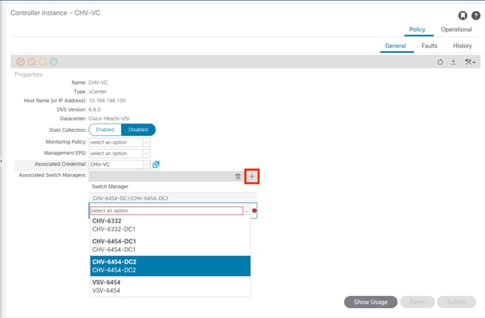
4. Select the DC2 Integration from the drop-down list.
5. Click Update.
When you complete these steps, the VMM managed vDS will communicate to both UCSM Integrations associated with the two DC UCS domains, creating EPG allocated VLANs within the uplinks of the FIs in both DCs, as well as the vNIC Templates used by the ESXi hosts in both DCs.
Hitachi GAD Deployment
![]() Do not continue until all physical cabling between VSPs, MDS, MCU/RCU, and quorum are completed.
Do not continue until all physical cabling between VSPs, MDS, MCU/RCU, and quorum are completed.
During this deployment procedure you must deploy the following:
· Correct port settings for GAD, non-GAD, and quorum on each respective VSP.
· Boot, non-GAD, local and remote GAD, and quorum host groups on each respective VSP.
· Back end Pools for boot LUNs and VMFS LDEVs on systems at data center DC1 and DC2.
· VSM creation and emulation with the reservation of common components between the two VSPs that are perform GAD replication via RAIDCOM.
· Replication Hitachi Online Replication Manager (HORCM) file for replication.
Physical VSP Connections at Data Centers 1, 2 and 3
The following tables indicate the physical connections for each VSP system used within this validation for the MDS and remote VSP systems. Throughout the deployment the following tables will be referenced:
Table 38 DC1 VSP 5100 Connections
| Local Device |
Local Port |
Used For |
Connection |
Remote Device |
Remote Port |
| Hitachi VSP 5100 |
CL1-A |
Boot LUNs/Non-GAD |
32Gb FC |
Cisco MDS 9706 A |
FC 1/11 |
| CL1-C |
Boot LUNs/Non-GAD |
32Gb FC |
Cisco MDS 9706 B |
FC 1/11 |
|
| CL2-A |
Boot LUNs/Non-GAD |
32Gb FC |
Cisco MDS 9706 A |
FC 1/12 |
|
| CL2-C |
Boot LUNs/Non-GAD |
32Gb FC |
Cisco MDS 9706 B |
FC 1/12 |
|
| CL1-B |
GAD VMFS |
32Gb FC |
Cisco MDS 9706 A |
FC 1/13 |
|
| CL1-D |
GAD VMFS |
32Gb FC |
Cisco MDS 9706 B |
FC 1/13 |
|
| CL2-B |
GAD VMFS |
32Gb FC |
Cisco MDS 9706 A |
FC 1/14 |
|
| CL2-D |
GAD VMFS |
32Gb FC |
Cisco MDS 9706 B |
FC 1/14 |
|
| CL7-A |
MCU-RCU |
32Gb FC |
VSP G370 |
CL8-A |
|
| CL8-A |
MCU-RCU |
32Gb FC |
VSP G370 |
CL7-A |
|
| CL7-C |
RCU-MCU |
32Gb FC |
VSP G370 |
CL8-B |
|
| CL8-C |
RCU-MCU |
32Gb FC |
VSP G370 |
CL7-B |
|
| CL7-D |
RCU-Quorum |
16Gb FC |
VSP G1500 |
CL1-K |
|
| CL8-D |
RCU-Quorum |
16Gb FC |
VSP G1500 |
CL1-B |
|
| SVP LAN |
|
GbE |
GbE management switch |
Any |
Table 39 DC2 VSP G370 Connections
| Local Port |
Used For |
Connection |
Remote Device |
Remote Port |
|
| Hitachi VSP G370 |
CL1-A |
Boot LUNs/Non-GAD |
32Gb FC |
Cisco MDS 9148T A |
FC 1/5 |
| CL3-B |
Boot LUNs/Non-GAD |
32Gb FC |
Cisco MDS 9148T B |
FC 1/5 |
|
| CL2-B |
Boot LUNs/Non-GAD |
32Gb FC |
Cisco MDS 9148T A |
FC 1/6 |
|
| CL4-A |
Boot LUNs/Non-GAD |
32Gb FC |
Cisco MDS 9148T B |
FC 1/6 |
|
| CL3-A |
GAD VMFS |
32Gb FC |
Cisco MDS 9148T A |
FC 1/15 |
|
| CL1-B |
GAD VMFS |
32Gb FC |
Cisco MDS 9148T B |
FC 1/15 |
|
| CL2-A |
GAD VMFS |
32Gb FC |
Cisco MDS 9148T A |
FC 1/16 |
|
| CL4-B |
GAD VMFS |
32Gb FC |
Cisco MDS 9148T B |
FC 1/16 |
|
| CL8-A |
MCU-RCU |
32Gb FC |
VSP 5100 |
CL7-A |
|
| CL7-A |
MCU-RCU |
32Gb FC |
VSP 5100 |
CL8-A |
|
| CL8-B |
RCU-MCU |
32Gb FC |
VSP 5100 |
CL7-C |
|
| CL7-B |
RCU-MCU |
32Gb FC |
VSP 5100 |
CL8-C |
|
| CL5-B |
MCU-Quorum |
16Gb FC |
VSP G1500 |
CL4-B |
|
| CL6-B |
MCU-Quorum |
16Gb FC |
VSP G1500 |
CL4-K |
|
| Cont1 LAN |
|
GbE |
SVP |
LAN 3 |
|
| Cont2 LAN |
|
GbE |
SVP |
LAN 4 |
Table 40 Remote Quorum VSP G1500 Connections:
| Local Device |
Local Port |
Used For |
Connection |
Remote Device |
Remote Port |
| VSP G1500 |
CL1-K |
MCU-Quorum |
16Gb FC |
VSP 5100 |
CL7-D |
| CL1-B |
MCU-Quorum |
16Gb FC |
VSP 5100 |
CL8-D |
|
| CL4-B |
RCU-Quorum |
16Gb FC |
VSP G370 |
CL5-B |
|
| CL4-K |
RCU-Quorum |
16Gb FC |
VSP G370 |
CL6-B |
|
| SVP LAN |
|
GbE |
GbE management switch |
Any |
These connections represent ports needed to support GAD connectivity, and the VSP to VSP connections shown above were used in the validation lab without any FC distance simulation present. In a production deployment, Hitachi Professional Services should be involved to discuss the replication technologies and distances supported.
For VSP system interoperability for replication technologies, refer to:
For extended replication for the interoperability between xWDM devices, refer to :
Configure Fibre Channel Ports at DC1 for Local Boot LUNs and VMFS Storage
For Hitachi Virtual Storage Platform fibre channel ports to be exposed properly for to the Cisco UCS components, modification of the ports from their default values must be performed. Prior to beginning this section, ensure that you have credentials on the Hitachi Virtual Storage Platform that have at least the Administrator role permissions within Hitachi Storage Navigator. Your partner or Hitachi services personnel provide credentials to your Hitachi Virtual Storage Platform after initial setup and configuration of the storage system.
Configure VSP 5100 Boot LUN and Non-GAD Storage Port Attributes
Attributes for ports used for provisioning host server boot LUNs and non-GAD storage have modified port settings. To define boot LUN and non-GAD port attributes follow these steps:
1. Access Hitachi Storage Navigator through a web browser. With the VSP 5000 series, the Storage Navigator interface will follow this format: https://<IP of Storage System SVP>/sanproject/emergency.do. For example, if the Storage System SVP IP address is 10.0.0.2, the URL would be: https://10.0.0.2/sanproject/emergency.do
2. Log into Hitachi Storage Navigator.
3. From the left Explorer pane, select the Storage Systems tab.
4. Expand the storage system being configured. Highlight the Ports/Host Groups/iSCSI Targets element in the navigation tree, then click the Ports tab in the main configuration pane.

5. Select the checkboxes for the ports being used for boot LUN and non-GAD provisioning within the solution, then click the Edit Ports button to instantiate the Edit Ports dialog box.
6. Select checkboxes to edit the following settings to modify the selected ports:
a. Port Attribute: Target
b. Port Security: Enabled
c. Port Speed: 32GB
d. Fabric: ON
e. Connection Type: P-to-P
7. Example ports used as boot lun and non-GAD ports for VSP 5100 in this design are listed in Table 13 .

8. Click OK for any warning that appears.
9. Click Finish.
10. Review the changes to be made and check the Go to tasks window for status box, then click Apply.
Configure Fibre Channel Ports at DC2 for Local Boot LUNs and VMFS Storage
The respective remote system at DC2 must also have modified port attributes based off design requirements, modification of the ports from their default values must be performed. Prior to beginning this section, ensure that you have credentials on the Hitachi Virtual Storage Platform that have at least the Administrator role permissions within Hitachi Storage Navigator. Your partner or Hitachi services personnel provide credentials to your Hitachi Virtual Storage Platform after initial setup and configuration of the storage system.
Configure VSP G370 Boot LUNs and Non-GAD Storage Port Attributes
Attributes for ports used for provisioning host server boot LUNs and Non-GAD storage on the VSP G370 at DC2 will require modified settings. See section Configure Fibre Channel Ports on Hitachi Virtual Storage Platform found in the Cisco and Hitachi Adaptive Solutions for Converged Infrastructure with Cisco ACI Deployment Guide.
Configure Host Connectivity and Presentation for Storage on Hitachi Virtual Storage Platform at DC1 and DC2
Create Boot LUN and Non-GAD Volume Host Groups for DC1 VSP 5100
Individual host groups must be created on each physical fibre channel port on the VSP for each vHBA attached to its respective fabric. The number of host groups created depend on the number of paths per LDEV. Make sure you have documented the specific ports on each fabric used on the VSP, their WWNs, and each vHBA WWPN before you proceed with this section and make sure that all initiators for the UCS Service Profiles you will be creating host groups for display as logged into the respective VSP fibre channel ports. The following host groups will contain the boot luns and non-GAD related VMFS datastores for DC1.
To check the initiator logins and to create boot local host groups for DC1, follow these steps:
1. Navigate to the SVP IP address and login.
2. From the navigation tree, select Ports/Host Groups/iSCSI Targets.
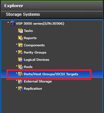
3. Select the Login WWNs/iSCSI Names tab.
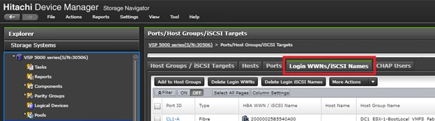
4. Review the list of WWNs and associated ports. You should be able to see each vHBA assigned to each fabric associated with each port on the VSP to which it is zoned.
5. Click the column names to sort the information to make this task easier or utilize the Filter feature to limit the number of records displayed. If any vHBA WWNs do not show in the list, go back and double-check the zoning configuration on the MDS.
6. With the Ports/Host Groups/iSCSI Targets element in the navigation tree still selected, click the Host Groups/iSCSI Targets tab.
7. Click Create Host Groups to instantiate the Create Host Groups dialog box.
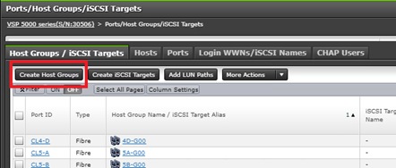
8. Host groups will be created separately for fabric A and fabric B vHBAs. Start with the fabric A host group for an individual UCS Service Profile and modify the following within the Create Host Groups dialog box:
- Host Group Name: Provide a descriptive name for the host and ensure there is an identifier for the fabric you are configuring, data center, server and provisioning type (i.e., DC1_ESX-1-BootLocal_VMFS_Fab_A, DC1_ESX-1-BootLocal_VMFS_Fab_B)
- Host Mode: Select 21 [VMware Extension] from the drop-down list.
- Host Mode Options: For each of the following Host Mode Options, find the Mode Number in the pane, select the checkbox, and click the Enable button:
§ 54 – (VAAI) Support Option for the EXTENDED COPY command
§ 63 – (VAAI) Support option for vStorage APIs based on T10 standards
§ 114 – The automatic asynchronous reclamation on ESXi6.5 or later
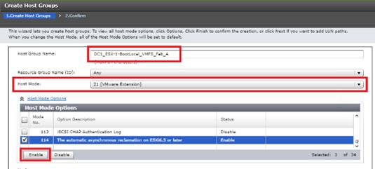
9. Write down the WWN information from the previous Create Device Aliases section.
10. Within the Available Hosts section, click Filter.
11. Create an Attribute/Value filter of:
a. HBA WWN
b. Using “contains” as a qualifier
c. Using the last four characters of the Fabric A initiator for the host
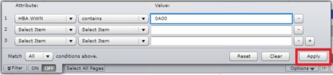
12. Click Apply.
13. Click Filter again to hide the filter rules dialog box.
14. Select the checkbox for the first port shown in the filtered list within the Available Hosts section.
15. Within the Available Ports section, check the checkboxes for all ports zoned to the host within Fabric A only, Click Add.
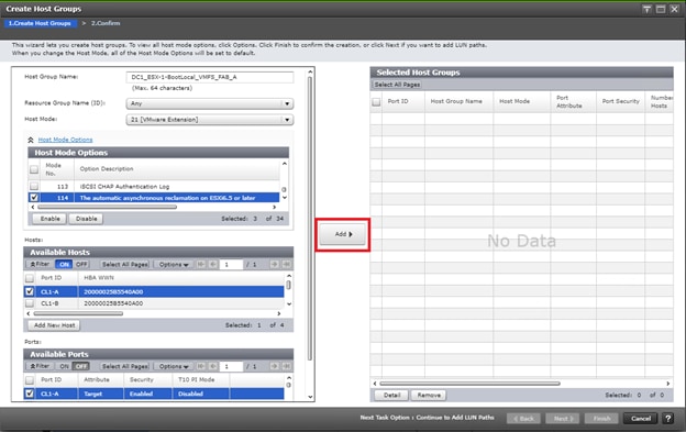
16. Click Finish.
![]()
17. Review the host group configuration for the Fabric A host groups for the UCS Service Profile being configured.
18. Click Apply.

19. Repeat steps 1-18 to create the host groups for all remaining initiator WWN at DC1 from the Fabric A and Fabric B tables for boot local host groups, be sure to use a descriptive names for the hosts based off data center, Fabric A or B, host number as well as an identifier to represent local boot LUNs along with non-GAD volumes.
Create Boot LUN and Non-GAD Volume Host Groups for DC2 VSP G370
Once the DC1 host groups are made, you will need to create host groups which hold boot LUNs and Non-GAD volumes on the DC2 array. To do so, follow section Create Host Groups for Cisco UCS Server vHBAs on Each Fabric found in the Cisco and Hitachi Adaptive Solutions for Converged Infrastructure with Cisco ACI Deployment Guide.
![]() Provide a descriptive name for the host and make sure there is an identifier for the fabric you are configuring (for example., DC2_ESX-1-BootLocal_VMFS_Fab_A, DC2_ESX-1-BootLocal_VMFS_Fab_B )
Provide a descriptive name for the host and make sure there is an identifier for the fabric you are configuring (for example., DC2_ESX-1-BootLocal_VMFS_Fab_A, DC2_ESX-1-BootLocal_VMFS_Fab_B )
Create a Hitachi Dynamic Provisioning Pool for Cisco UCS Server Boot LDEVs for DC1 VSP 5100
The configuration steps in this section assume that parity groups and LDEVs have been configured on the Hitachi VSP as part of the solution build/configuration by a partner or Hitachi professional services. If parity groups have not been configured on the Hitachi VSP, please reference the Hitachi Storage Virtualization Operating System documentation for creating parity groups before continuing with this section.
Make sure that you have planned which parity groups and LDEVs to use for your specific storage requirements. Your configuration may vary based on the types of drives ordered with your VSP and the parity groups configured on it.
To begin the provisioning process to create the boot LDEVs that will be used as boot LUNs for DC1, follow these steps:
1. Log into Hitachi Storage Navigator.

2. From the left Explorer pane select the Storage Systems tab and select Pools.
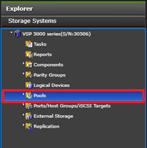
3. Click Create Pools to instantiate the Create Pools dialog box.
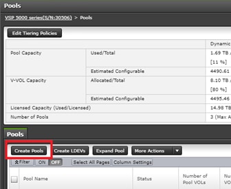
4. Configure the following items in the Create Pools dialog box:
a. Pool Type : Dynamic Provisioning
b. System Type : Open [Only an option when configuring the VSP 5x00 or VSP G1x00 systems]
c. Multi-Tier Pool : Disable
d. Data Direct Mapping: Disable
e. Pool Volume Selection: Manual
5. Click Select Pool VOLs.
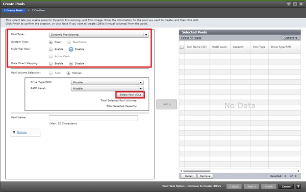
6. Within the left pane of the Select Pool VOLs dialog box, select the checkbox next to the LDEVs to be used for the UCS server boot LDEV dynamic provisioning pool.
7. Click Add to move the selected LDEV to the right pane of the dialog, then click OK to return to the Create Pools dialog box.
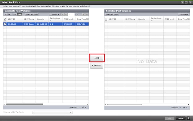
8. You should now see values for Total Selected Pool Volumes and Total Selected Capacity shown under the Select Pool VOLs button. Give the dynamic provisioning pool a descriptive Pool Name, then click Add to add the pool to be created to the Selected Pools pane in the dialog.
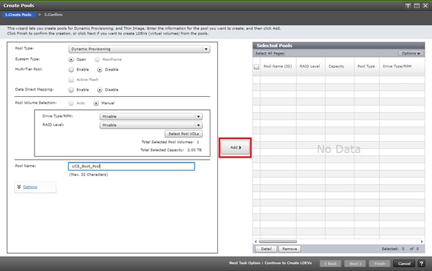
9. Click Finish.
10. Review the configuration for the pool to be created in the Create Pools confirmation dialog box and ensure the Go to tasks window for status checkbox is checked, then click Apply.
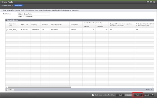
11. The tasks status window will appear, wait for the task status to show complete before moving onto the next step.
Create a Hitachi Dynamic Provisioning Pool for Cisco UCS Server Boot LDEVs for DC2 VSP G370
The configuration steps in this section assume that parity groups and LDEVs have been configured on the Hitachi VSP as part of the solution build/configuration by a partner or Hitachi professional services. If parity groups have not been configured on the Hitachi VSP, please reference the Hitachi Storage Virtualization Operating System documentation for creating parity groups before continuing with this section.
Make sure that you have planned which parity groups and LDEVs to use for your specific storage requirements. Your configuration may vary based on the types of drives ordered with your VSP and the parity groups configured on it.
In the Cisco and Hitachi Adaptive Solutions for Converged Infrastructure with Cisco ACI Deployment Guide, follow the steps in section Create a Hitachi Dynamic Provisioning Pool for UCS Server Boot LDEVs to create an HDP pool on VSP G370 at DC2.
Create Boot LDEVs for Each Cisco UCS Service Profile and Add LDEV Paths at DC1 VSP 5100
Individual boot LDEVs must be created for each Cisco UCS Service Profile for the ESXi hypervisor to be installed onto. Prior to beginning these steps, make sure you have identified the fibre channel ports on the Hitachi VSP that will be used for presentation of the boot LDEVs to the Cisco UCS servers. Please note that a maximum of four paths can be used within the Cisco UCS Service Profile (two on each fabric) as boot targets. After creating a pool that will supply boot LDEVs for DC1 hosts, you must create the boot LDEVs and map them to the respective host groups for DC1 system.
To create boot LDEVs and to Add LDEV paths to the host groups, follow these steps:
1. Log into Storage Navigator for the respective VSP 5100 system at datacenter 1.
2. From the left Explorer pane within Hitachi Storage Navigator, select the Storage Systems tab and expand the storage system being configured.
3. Expand the Pools element in the navigation tree and highlight the UCS Boot pool previously created for use as the backing storage for the UCS boot LDEVs.
4. Select the Virtual Volumes tab in the right-hand pane and click Create LDEVs to instantiate the Create LDEVs dialog.
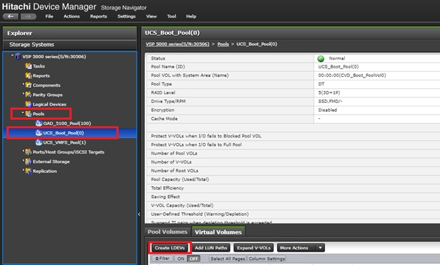
5. Modify the following within the Create LDEVs dialog:
a. LDEV Capacity: Enter the capacity desired for the UCS Service Profile boot LDEV. Note that ESXi requires a minimum of 5.2GB for a boot LDEV as documented by VMware.
b. Number of LDEVs: 1
c. LDEV Name: Provide a descriptive name and numeric identifier for the boot LDEV. For ease of identification, it is recommended that the server name or other identifier specific to the service profile being configured be entered in the Prefix field.
6. Click Add and verify that the boot LDEV is listed in the right-hand Selected LDEVs pane, then click Next.
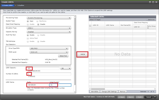
7. The Select LDEVs screen shows the selected LDEVs to which the paths will be added.
8. Make sure the newly created boot LDEV is the only LDEV in the Selected LDEVs pane, then click Next.
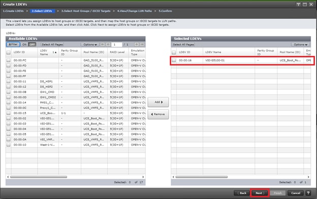
9. The Select Host Groups/iSCSI Targets screen shows all the host groups that can be assigned to the boot LDEV as a path.
10. Click Filter, then create an Attribute/Value filter:
a. Host Group Name
b. Using “Contains” as a qualifier
c. Value <ESX-X-BootLocal> which contains text unique to UCS server profile
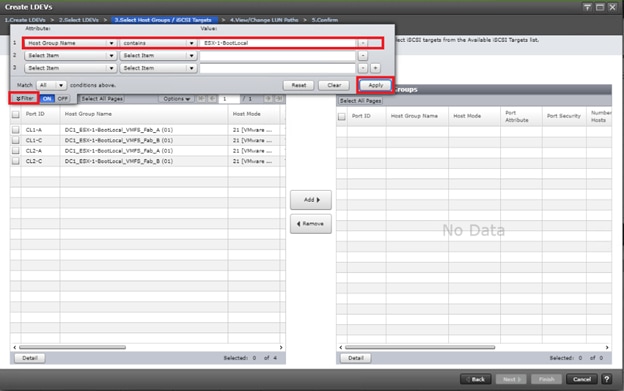
11. Click Apply.
12. Click Filter again to hide the filter rules dialog box.
13. Select the checkboxes for the ports being used as boot LDEV paths in your configuration. Depending on the pathing design used, you may have fewer than four paths for the boot LDEV, but there should be a minimum of one path per fabric used.
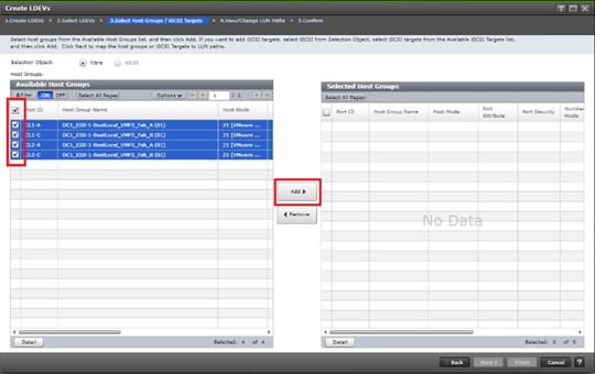
14. Click Add to populate the Selected Host Groups pane with the selected host groups, then click Next.
15. The View/Change LUN Paths screen shows the LDEV you are adding paths to and the associated host LUN ID that will be presented to the host on a per path basis.
16. Use the scrollbar at the bottom of this screen to review the LUN ID assigned and ensure that all LUN IDs are set to zero, then click Finish.
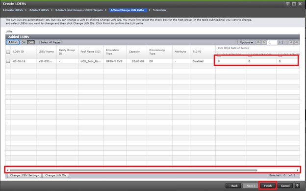
17. Review the LDEV details and LUN ID configuration of the boot LDEV being created, then click Apply to create the LDEV and add paths to the UCS Service Profile.
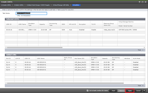
18. Repeat steps 1-16 to create the boot LDEVs and to assign paths for all other UCS Service Profiles for DC1 hosts, using a unique LDEV name and associated Host Group Name associated to each UCS Service Profile.
Create Boot LDEVs for Each Cisco UCS Service Profile and Add LDEV Paths DC2 VSP G370
Individual boot LDEVs must be created for each UCS Service Profile for the ESXi hypervisor to be installed. Prior to beginning these steps, make sure you have identified the fibre channel ports on the Hitachi VSP that will be used for the presentation of the boot LDEVs to the UCS servers. Please note that a maximum of four paths can be used within the UCS Service Profile (two on each fabric) as boot targets. After creating a pool that will supply boot LDEVs for DC2 hosts, you must create boot the LDEVs and map them to the respective host groups for the DC2 system.
Follow the steps in section Create Boot LDEVs for EACH UCS Service Profile and ADD LDEV Paths found in the Cisco and Hitachi Adaptive Solutions for Converged Infrastructure with Cisco ACI Deployment Guide.
Create a Hitachi Dynamic Provisioning Pool for Cisco UCS Server VMFS Volume LDEVs for DC1 VSP 5100
Follow the steps in section Create a Hitachi Dynamic Provisioning Pool for Cisco UCS Server Boot LDEVs for DC1 VSP 5100 to create the dynamic provisioning pool for the Cisco UCS Server VMFS volume LDEVs, selecting the Drive Type/RPM, RAID Level, and number of Pool VOLs desired for the pool backing the VMFS volumes in the solution.
Create a Hitachi Dynamic Provisioning Pool for Cisco UCS Server VMFS Volume LDEVs for DC2 VSP G370
Follow the steps in section Create a Hitachi Dynamic Provisioning Pool for Cisco UCS Server Boot LDEVs for DC2 VSP G370 system to create the dynamic provisioning pool for the UCS Server VMFS volume LDEVs, selecting the Drive Type/RPM, RAID Level, and number of Pool VOLs desired for the pool backing the VMFS volumes in the solution.
Create a Shared VMFS Non-GAD LDEV and Add LUN Paths with DC1 VSP 5100
VMFS LDEVs need to be created for shared VMFS volumes used for virtual machine storage across multiple ESXi servers which share resources within a vSphere cluster. Prior to beginning these steps, make sure you have identified the fibre channel ports on the Hitachi VSP that will be used for presentation of the VMFS LDEVs to the UCS servers. Depending on the pathing design you are using, additional or fewer paths may be configured as compared to the steps below.
To allocate a VMFS datastore to DC1 hosts for non-GAD VMFS storage, follow these steps:
![]() A minimum of two paths should be used for shared VMFS LDEVs (one path per fabric).
A minimum of two paths should be used for shared VMFS LDEVs (one path per fabric).
1. From the left Explorer pane within Hitachi Storage Navigator, select the Storage Systems tab and expand the storage system being configured.
2. Expand the Pools element in the navigation tree and highlight the pool previously created for use as the backing storage for VMFS volumes, select the Virtual Volumes tab in the right-hand pane, and click Create LDEVs to instantiate the Create LDEVs dialog.
3. Modify the following within the Create LDEVs dialog:
a. LDEV Capacity: Enter the capacity desired for the VMFS LDEV.
b. Number of LDEVs: 1
c. LDEV Name: Provide a descriptive name and numeric identifier for the VMFS LDEV. For ease of identification, it is recommended that the cluster name or other identifier specific to the VMFS volume being configured be entered in the Prefix field.
4. Click Add and verify that the VMFS LDEV is listed in the right-hand Selected LDEVs pane, then click Next.
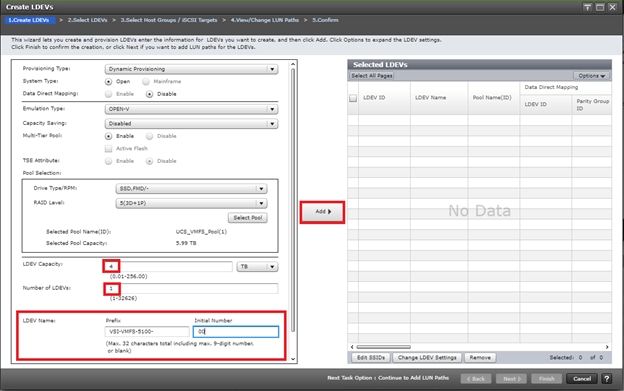
5. The Select LDEVs screenshot shows the selected LDEVs to which the paths will be added.
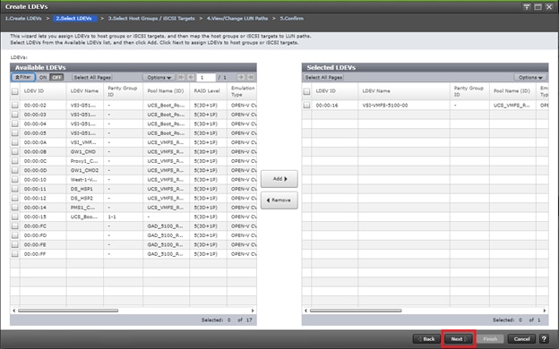
6. Make sure the newly created VMFS LDEV is the only LDEV in the Selected LDEVs pane, then click Next.
7. The Select Host Groups/iSCSI Targets screen shows all the host groups that can be assigned to the VMFS LDEV as a path.
8. Click Filter, then create multiple Attribute/Value:
a. Host Group Name
b. Using “contains” as a qualifier
c. Value <BootLocal> which contains text unique to UCS server profiles to use the VMFS volume
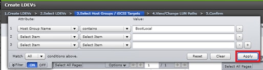
9. Click Apply.
10. Click Filter to hide the filter rules dialog box.
11. Select the checkboxes for the ports being used as VMFS LDEV paths in your configuration.
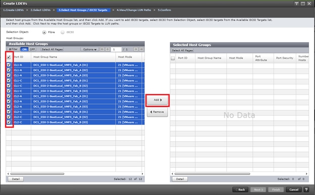
![]() Depending on the pathing design used, you may have additional or fewer than four paths for the VMFS LDEV, but there should be a minimum of one path per fabric used.
Depending on the pathing design used, you may have additional or fewer than four paths for the VMFS LDEV, but there should be a minimum of one path per fabric used.
12. Click Add to populate the Selected Host Groups pane with the selected host groups, then click Next.
The View/Change LUN Paths screen displays the LDEV you are adding paths to and the associated host LUN ID that will be presented to the host on a per path basis.
13. Use the scrollbar at the bottom of this screen to review the LUN ID assigned and ensure that all LUN IDs are set to a consistent value other than zero for all paths.
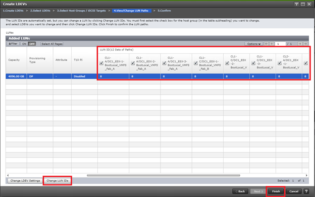
![]() If other LDEVs have been assigned to one host but not others, you will need to modify the Host LUN ID assignment to the next Host LUN ID that is consecutive across all hosts/paths.
If other LDEVs have been assigned to one host but not others, you will need to modify the Host LUN ID assignment to the next Host LUN ID that is consecutive across all hosts/paths.
14. Make sure you use the scrollbar at the bottom of the dialog to double-check that all Host LUN IDs are set consistently across all paths.
15. Select the checkbox for all ports/paths listed, select the checkbox for the LDEV ID on the left side of the pane, then click Change LUN IDs.
16. The Change LUN IDs dialog will appear; enter the next Host LUN ID available across all paths, then click Finish.
17. Review the LDEV details and LUN ID configuration of the VMFS LDEV being created.
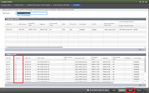
![]() If the output is long enough, use the scrollbar on the right side of the Added LUNs window to make sure the LUN ID column contains the same LUN ID for each port listed.
If the output is long enough, use the scrollbar on the right side of the Added LUNs window to make sure the LUN ID column contains the same LUN ID for each port listed.
18. Click Apply to create the LDEV and add paths to the UCS Service Profiles which will share this LDEV as a VMFS volume.
19. Repeat steps 1-19 to create additional shared VMFS LDEVs and to assign paths for all UCS Service Profiles which will share access to the VMFS LDEVs used for VMFS volumes.
Create a Shared VMFS Non-GAD LDEV and Add LUN Paths with DC2 VSP G370
VMFS LDEVs need to be created for shared VMFS volumes used for virtual machine storage across multiple ESXi servers which share resources within a vSphere cluster. Prior to beginning these steps, make sure you have identified the fibre channel ports on the Hitachi VSP that will be used for presentation of the VMFS LDEVs to the UCS servers. Depending on the pathing design you are using, additional or fewer paths may be configured.
![]() A minimum of two paths should be used for shared VMFS LDEVs (one path per fabric).
A minimum of two paths should be used for shared VMFS LDEVs (one path per fabric).
To allocate a VMFS datastore to DC2 hosts for non-GAD VMFS storage, follow the steps in section Create Shared VMFS LDEVs and Add LDEV paths found in the Cisco and Hitachi Adaptive Solutions for Converged Infrastructure with Cisco ACI Deployment Guide.
Prepare for GAD Pair Creation
Pair Management Server
A pair management server runs on a Windows or Linux operating systems and allows you to have a direct line of communication with Hitachi RAID storage systems to orchestrate system settings as well as replication pairs. A pair management server consists of the following:
· Hitachi Command Control Interface (CCI) Software
· Command Device (CMD) IP or Physical
· Hitachi Online Replication Control Manager Files (HORCM)
CMD make this possible by allowing HORCM to directly communicate with the array using the binaries installed via the CCI library. HORCM Files define both the connection method to an array and any replication to be controlled. A HORCM file can only control a single storage system, therefore it is very important to know which instance you are working with.
There are two types of HORCM files, one type specifically for RAIDCOM (Hitachi’s CLI configuration utility), and one for controlling replication. HORCM, when started, becomes a daemon which will listen on a specified UDP port as defined within each HORCM file. All remote replication tasks including high availability GAD requires a secondary instance to communicate with.
In a Raidcom Specific HORCM file there is one section required as indicated by the following:
· HORCM_CMD
- Defines the local CMDs, or the Remote IP Address of a singular array
Figure 29 Representation of a RAIDCOM HORCM File

In a traditional HORCM file used for replication, there are four sections which need to be defined and configured:
1. HORCM_MON. Defines the host IP Address to listen on, UDP Port, and timeout values
2. HORCM_CMD. Defines the local CMDs, or the Remote IP Address of a singular array
3. HORCM_LDEV / HORCM_LDEVG / HORCM_DEV. Defines one or more lists of devices participating in replication
4. HORCM_INST. The remote location of the list of devices
Figure 30 Representation of a Replication HORCM File
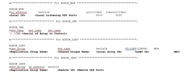
CCI operations can be performed using either the in-band method (all storage systems) or the out-of-band method (VSP and later).
· In-band (host-based) method. CCI commands are transferred from the client or server to the CMD in the storage system via the host fibre-channel or iSCSI interface. The CMD must be defined in the configuration definition file, as shown in the following figure.
· Out-of-band (LAN-based) method. CCI commands are transferred from a client PC via the LAN. For CCI on models after VSP, you can create a virtual CMD in the SVP by specifying the IP address in the configuration definition file. For CCI on VSP Gx00 models and VSP Fx00 models, you can create a virtual CMD in GUM in a storage system by specifying the IP address of a storage system. By creating a virtual CMD, you can execute the same script as the in-band method from a client PC which is not connected directly to a storage system. CCI commands are transferred to the virtual CMD from the client PC, and then executed in storage systems. A virtual CMD can also be created on the CCI server, which is a remote CCI installation that is connected by LAN. The location of the virtual CMD depends on the type of storage system. Figure 31 shows the example communication for In-band and Out-of-band system communication.
Figure 31 Example of In-band and Out-of-band Communication with HORCM Configuration
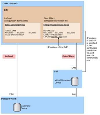
This guide explains the procedures on how to setup a pair management server on a Windows operating system, which HORCM files for both RAIDCOM and pair replication management. It is assumed that the Windows server has already been installed and is able to communicate with the network.
Install Hitachi Command Control Interface (CCI) on Pair Management Server
To begin the setup of Hitachi’s CCI software, follow these steps:
1. Login into your Windows server with a user with Administrative privileges.
2. Locate and expand on the imported CCI binaries.
3. Select and launch Setup.exe.
4. On the welcome screen select Next.
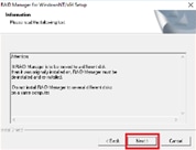
5. On the next page, read and confirm the banner message, click Next.
6. Define the destination installation folder as the default value C:\HORCM, click Next to complete installation of CCI.
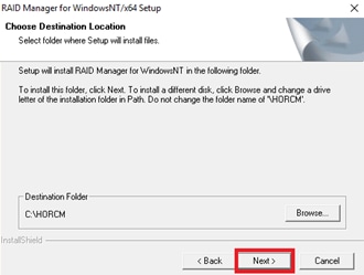
7. Repeat steps 1-6 to install CCI on your secondary pair management server.
Create LDEV for CMD on DC1 VSP 5100
After installing CCI, a CMD must be allocated to the server in which you have installed your CCI binaries to be able to communicate with your RAID subsystem.
![]() Make sure the device that will be set as a CMD does not contain any user data. Once a volume is set as a CMD, it is inaccessible to the host.
Make sure the device that will be set as a CMD does not contain any user data. Once a volume is set as a CMD, it is inaccessible to the host.
To create a LDEV to be used as a CMD, follow these steps:
1. Log into Hitachi Storage Navigator.
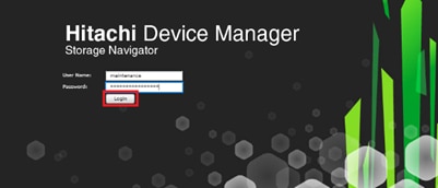
2. From the left Explorer pane select the Storage Systems tab.
3. Expand the storage system begin configured. Highlight Logical Devices in the navigation tree and click Create LDEVs.
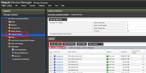
4. In the create LDEV wizard select your Provisioning Type as Dynamic Provisioning.
5. Select an available pool from the Drive Type/RPM Raid Level drop-down list and click Select Pools.
6. From the available pools list select a pool and click OK.
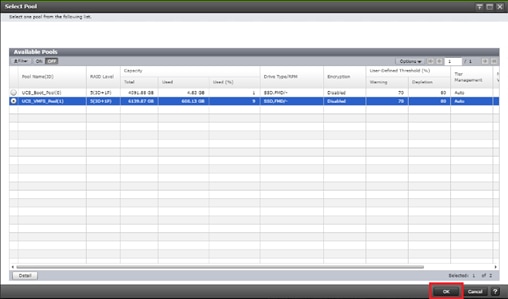
7. Define LDEV capacity as <100MB, set the number of LDEVs to 1, and define an applicable LDEV name.
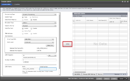
8. Click Add to define out the selected LDEVs.
9. Click Finish to view task summary.
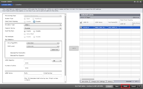
10. 10. Click Apply to kick of CMD creation.
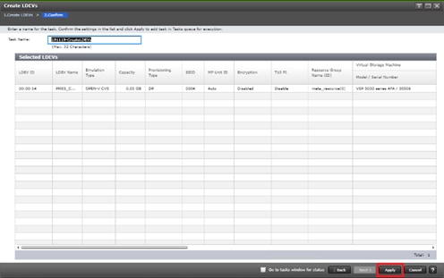
Create LDEV for CMD on DC2 VSP G370
After installing CCI, a CMD must be allocated to the server in which you have installed your CCI binaries to communicated with your RAID subsystem.
To create a LDEV to be used as a CMD, follow these steps:
1. Log into Hitachi Storage Navigator.

2. From the left Explorer pane select the Storage Systems tab.
3. Expand the storage system begin configured. Highlight Logical Devices in the navigation tree and click Create LDEVs.
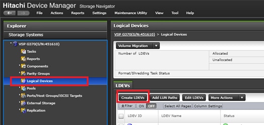
4. In the create LDEV wizard select your Provisioning Type as Dynamic Provisioning.
5. Select an available pool from the Drive Type/RPM Raid Level drop down and click Select Pools.
6. From the available pools list select a pool and click OK.
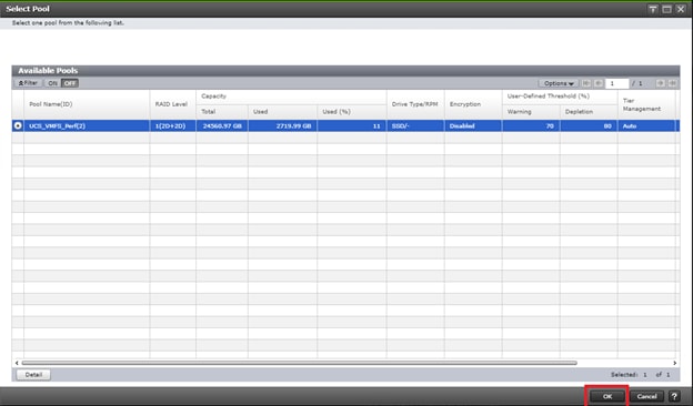
7. Define LDEV capacity as <100MB, set the number of LDEVs to 1, and define an applicable LDEV name.
8. Click Add to define out the selected LDEVs.
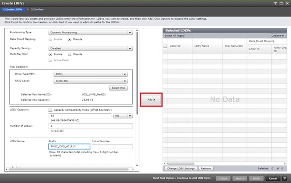
9. Click Finish to view task summary.
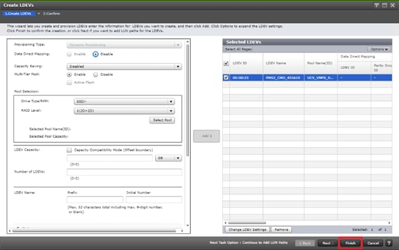
10. Click Apply to kick of CMD creation.
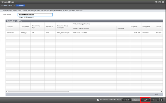
Define a New LDEV as a CMD
Once you have created a LDEV, you must select it and enable the CMD attribute. This process can be followed on both VSP 5100 and VSP G370 at DC1 and DC2.
To create the CMD, follow these steps.
1. Select the Logical Devices container from the navigation tree.
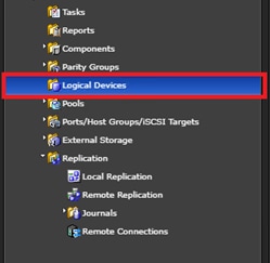
2. Find the newly created LDEV and select it for your CMD.
3. From the more actions drop-down list, choose Edit Command Devices.
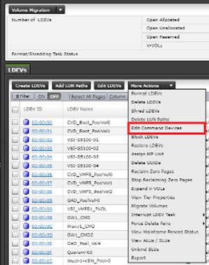
4. From the edit Command Devices wizard, set Command Device to Enabled, and Enable User Authentication. Click Finish.
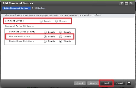
5. Execute the task by clicking Apply.
6. Repeat steps 1-5 on the alternate storage system.
Allocate the CMD to the Pair Management Server 1
Once you have configured your LDEV as a CMD, you must allocate it to your virtual server.
![]() Boot local host groups must be made prior using Storage Navigator.
Boot local host groups must be made prior using Storage Navigator.
To allocate the CMD via Storage Navigator for DC1 VSP 5100, follow these steps:
1. Select the Logical Devices container from the Navigation tree.
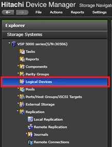
2. Select your CMD and select Add LUN Paths.
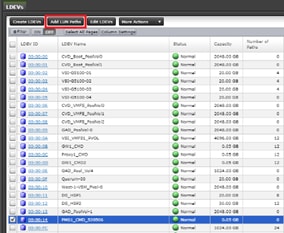
3. Using the Add LUN Paths wizard select Next.
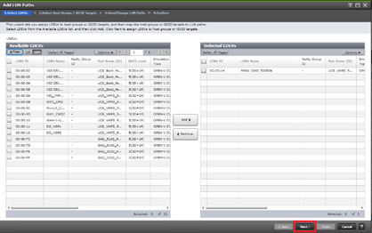
4. Click Filter, then create multiple Attribute/Value:
a. Host Group Name
b. Using “contains” as a qualifier
c. Value <BootLocal> which contains text unique to UCS server profiles to use the VMFS volume

5. On the Select Host Groups / iSCSI Targets select DC1 (DC1) boot local host groups and select Add.
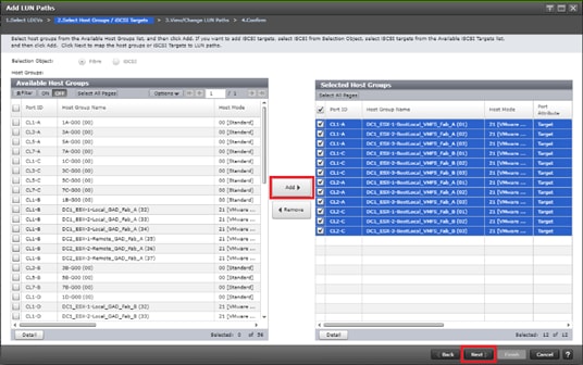
6. Finalize your selection by clicking Next.
7. On the Add LUN Paths window, confirm consistent LUN ID allocation. If your LUN ID is not consistent, select your paths along with the LDEV and click Change LUN IDs.
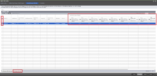
8. In the change LUN IDs window, update LUN ID to desired value. Click OK.
9. Select Finish to view a summary of the task.
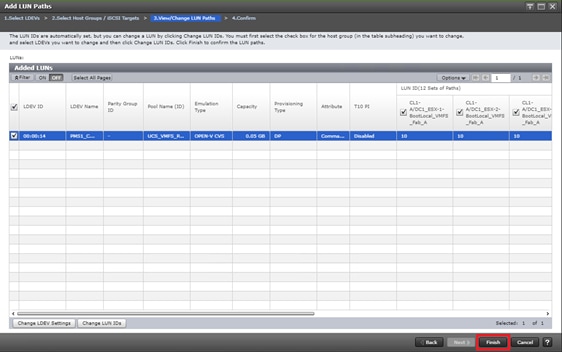
10. Click Apply to execute task.
Allocate the CMD to the Pair Management Server 2
Once you have configured your LDEV as a CMD, you must allocate it to your virtual server.
![]() Boot local host groups must be made prior using Storage Navigator.
Boot local host groups must be made prior using Storage Navigator.
To allocate the CMD using Storage Navigator for DC2 VSP G370, follow these steps:
1. Select the Logical Devices container from the Navigation tree.
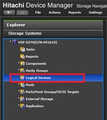
2. Select your CMD and select Add LUN Paths.
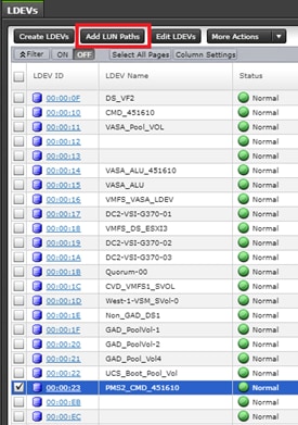
3. Using the Add LUN Paths wizard select Next.
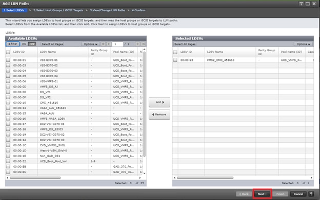
4. Click Filter, then create multiple Attribute/Value:
a. Host Group Name
b. Using “contains” as a qualifier
c. Value <BootLocal> which contains text unique to UCS server profiles to use the VMFS volume
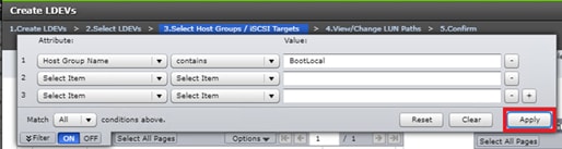
5. On the Select Host Groups / iSCSI Targets select DC2 boot local host groups and select Add.
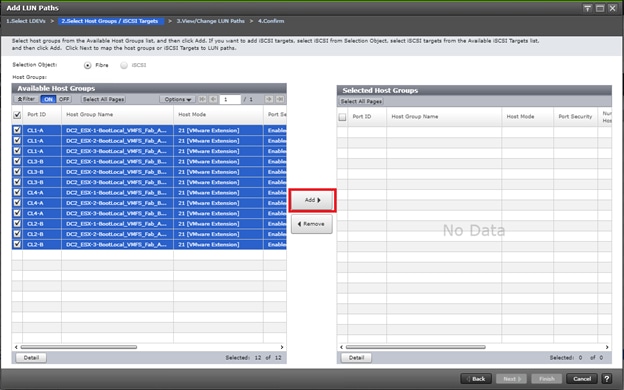
6. Finalize your selection by clicking Next.
7. On the Add LUN Paths window, confirm consistent LUN ID allocation. If your LUN ID is not consistent, select your paths along with the LDEV and click Change LUN IDs.
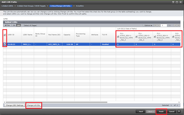
8. In the change LUN IDs window, update LUN ID to desired value. Click OK.
9. Select Finish to view a summary of the task
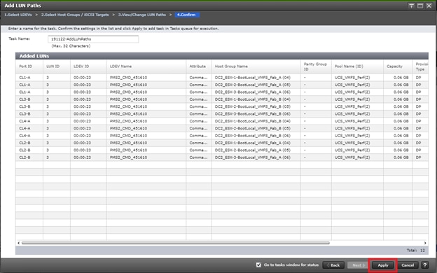
10. Click Apply to execute task.
Onboard the CMD to Pair Management Server as RAW Device Map using vCenter
Once a CMD is defined from your RAID subsystem and have provisioned to respective local and boot LUN host groups, you must onboard your CMD to your Pair Management Server at DC1 and DC2.
To map your CMD to your Pair Management Server via RAW device map, follow these steps:
1. Login to vSphere vCenter Server.
2. From the host and cluster view, right-click your Pair Management Server 1 and select Edit Settings…
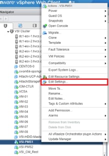
3. Using the new device drop-down list, select RDM Disk.
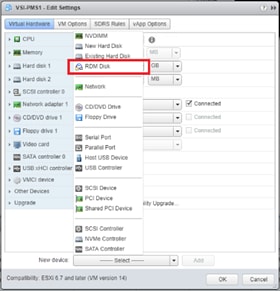
4. Select Add.
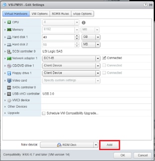
5. From the Select Target LUN list choose your presented CMD. Click OK.
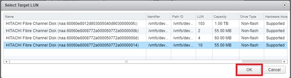
6. Using the Edit Settings menu finalize your selection by clicking OK. Your CMD is now presented to the operating system.
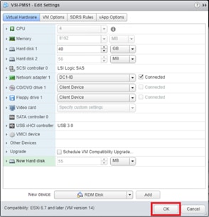
7. Repeat steps 1-6 for secondary subsystem CMD on Pair Management Server 2.
Setup CMD on Windows OS
After allocating a CMD to the Windows OS, you must verify its visibility.
![]() The following example utilizes the Windows 2016 Data Center operating system. To access components using different generations of a Windows operating system, you can utilize the following executables using RUN:
The following example utilizes the Windows 2016 Data Center operating system. To access components using different generations of a Windows operating system, you can utilize the following executables using RUN:
Diskmgmt.msc (Disk Management)
Cmd.exe (Command Prompt)
CMDs allow HORCM to communicate directly with the storage sub-system. To verify the CMD using the Windows 2016 Data Center, follow these steps:
1. Log into the Windows host.
2. From the desktop, right click on start and select Disk Management.
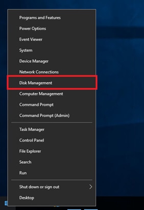
3. Using Disk Management, you will be able to see the CMD that you have RAW device mapped in the previous step. You do not have to online and initialize this volume. There is no further action needed.
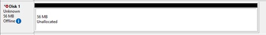
Verify CMD Physical Drive Details on Window OS with CCI
Once you have installed CCI binaries and have allocated a CMD device to your Windows host, you can verify CMD attributes using CCI.
To confirm CMD attributes, follow these steps:
1. Right-click the windows Start icon and select Command Prompt (Admin).
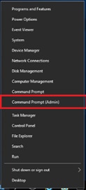
2. You must first navigate to the directory to which you have installed CCI. To access CCI binaries, change your Windows directory to C:\HORCM\ect.
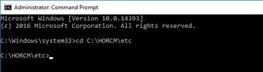
3. Run command raidscan -x findcmddev #(0-25), this will scan your system for any CMD s with drive numbers 0 to 25. In this case you can see your CMD is from our VSP 5100 system with serial 530506 linked to physical drive 1.
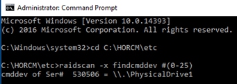
Create a RAIDCOM HORCM File with IP CMD for VSP 5100 DC1 Array Communication
Creating a RAIDCOM HORCM file will allow you to communicate with a Hitachi RAID subsystem and modify attributes. With a VSP 5100 system, you will specify the IP address of the SVP. Remember, a HORCM file administers a single array.
To create a RAIDCOM HORCM file, follow these steps:
1. Run windows command prompt as an administrator.

2. Use the administrative command prompt and open notepad.
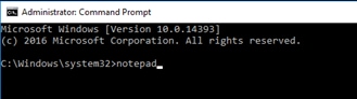
3. Within your notepad instance, write out the format for HORCM_CMD, by providing the IP address of the RAID system you would like to control. With a VSP 5100 system, you specify the IP address of the SVP.
![]()
4. Using Notepad, select File, Save As.
5. Navigate and save your HORCM file to C:\Windows.
6. Save your file as horcm10.conf, with type selection as All Files, click Save.
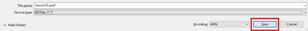
Create a RAIDCOM HORCM File with IP CMD for VSP G370 Data Center 2 Array Communication
To create a RAIDCOM HORCM file, follow these steps:
1. Run windows command prompt as an administrator.
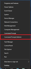
2. Using the administrative command prompt, open notepad.
3. Within your notepad instance, write out the format for HORCM_CMD, by providing the IP address of the RAID system you would like to control. With Hitachi’s G350, G370, G700, G900 systems you define both controller IP’s within the HORCM file.
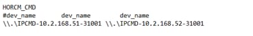
4. Using Notepad select File, Save As.
5. Navigate and save your HORCM file to C:\Windows.
6. Save your file as horcm11.conf, with type selection as All Files, click Save.
Start HORCM Files on Pair Management Server 1 and 2
Once HORCM files are defined, you must start the HORCM file to be able to communicate with the RAID Subsystem. To start a HORCM file follow these steps:
1. Navigate to the directory to which you have installed CCI. To access CCI binaries, change your windows directory to C:\HORCM\ect.
2. From the C:\HORCM\ect directory issue horcmstart.exe followed by the HORCM instance you want online.
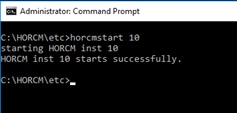
3. You can now issue command sets to the RAID subsystem to administer and modify components to the specified RAID system based off the defined HORCM file.
4. Repeat steps 1-3 for the HORCM file 11 on Pair Management Server 2.
Windows Firewall Settings for HORCM UDP Ports
Within production environments that utilize firewalls, you must configure a passthrough of UDP listener ports that is being utilized on each Pair Management Server via HORCM files.
To create windows firewall rules to allow HORCM UDP ports, follow these steps.
1. Log into your Pair Management Server, right-click Start.
2. Select Control Panel.
3. Click System and Security.
4. Click Windows Firewall.
5. Select Advanced settings.
6. Click Inbound Rules.
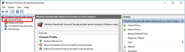
7. Click New Rule…
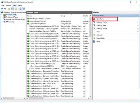
8. From the New Inbound Rule Wizard, select Port. Click Next.
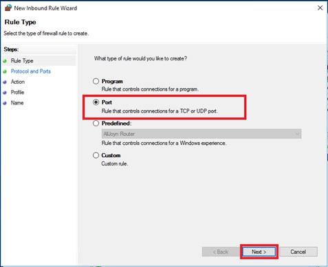
9. Select UDP and specify your local listening UDP port as defined in HORCM files. Click Next.
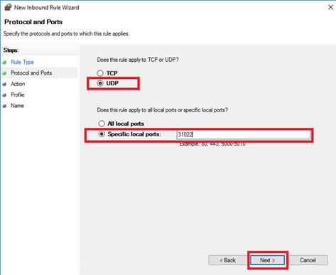
10. Select and apply the inbound rule to Domain, Private, and Public. Click Next.
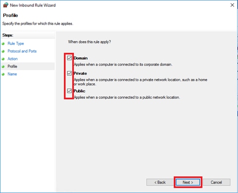
11. Select Allow the connection, click Next.
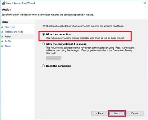
12. Finalize the rule by applying the name, click Finish.
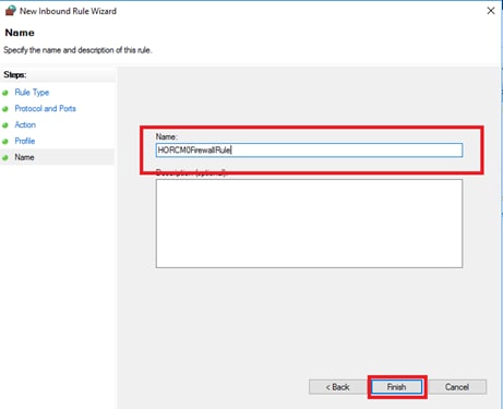
13. Confirm rule creation, using the inbound rules list.
14. Repeat steps 1-13 to create additional Windows Firewall rules for UDP listener ports utilized by HORCM files on Pair Management Server 1 and 2.
Configure VSP 5100 MCU/RCU port attributes
MCU and RCU ports between systems in replication carry production data to each VSP controller at DC1 or DC2. To configure the MCU and RCU fibre channel ports used for system replication within the VSP 5100 storage system, follow these steps:
1. Log into Hitachi Storage Navigator.
2. From the left Explorer pane, select the Storage System tab.
3. Expand the storage system being configured. Highlight the Ports/Host Groups/iSCSI Targets element in the navigation tree, then click the Ports tab in the main configuration pane.
4. Select the checkboxes for the ports being used for MCU/RCU system replication within the solution, then click Edit Ports to instantiate the Edit Ports dialog box.
5. Select checkboxes to edit the following settings to modify the selected ports:
a. Port Attribute: Bidirectional
b. Port Security: Disabled
c. Port Speed: Auto
d. Fabric: OFF
e. Connection Type: P-to-P
![]() Example ports used as MCU/RCU ports between VSP 5100 and VSP G370 in this design are listed in Table 13 .
Example ports used as MCU/RCU ports between VSP 5100 and VSP G370 in this design are listed in Table 13 .
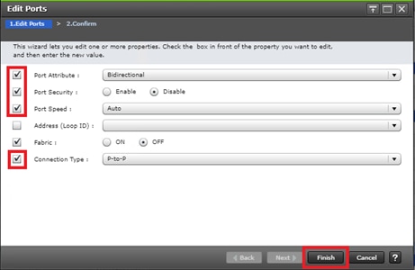
6. Click OK for any warning that appears.
7. Click Finish.
8. Review the changes to be made and check the Go to tasks window for status box, then click Apply.
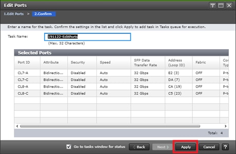
Configure VSP 5100 GAD Port attribute
There are specific ports for GAD storage allocation on data center 1 VSP 5100. The attributes for ports used for the GAD allocation will have different settings compared to the MCU/RCU ports. To define the GAD port attributes, follow these steps:
1. Log into Hitachi Storage Navigator.
2. From the left Explorer pane, select the Storage System tab.
3. Expand the storage system being configured. Highlight the Ports/Host Groups/iSCSI Targets element in the navigation tree, then click the Ports tab in the main configuration pane.
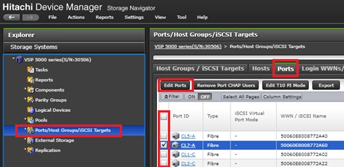
4. Select the checkboxes for the ports being used for GAD system replication within the solution, then click Edit Ports to instantiate the Edit Ports dialog box.
5. Select the checkboxes to edit the following settings to modify the selected ports:
a. Port Attribute: Target
b. Port Security: Enabled
c. Port Speed: 32GB
d. Fabric: ON
e. Connection Type: P-to-P
![]() Example ports used as GAD ports for VSP 5100 in this design are listed in Table 13 .
Example ports used as GAD ports for VSP 5100 in this design are listed in Table 13 .
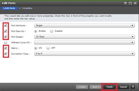
6. Click OK for any warning that appears.
7. Click Finish.
8. Review the changes to be made and check the Go to tasks window for status box, then click Apply.
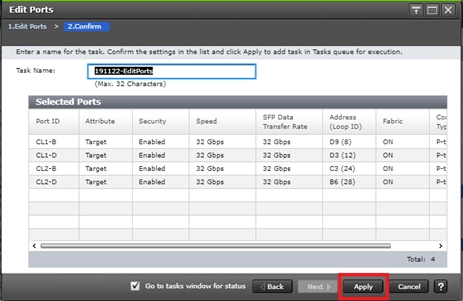
Configure VSP 5100 Quorum Port Attributes
Attributes for the ports used for the Quorum disk have custom settings when compared to the MCU/RCU and GAD/non-GAD ports. To define quorum port attributes, follow these steps:
1. Log into Hitachi Storage Navigator.
2. From the left Explorer pane, select the Storage System tab.
3. Expand the storage system being configured. Highlight the Ports/Host Groups/iSCSI Targets element in the navigation tree, then click the Ports tab in the main configuration pane.

4. Select the checkboxes for the ports being used for Quorum within the solution, then click Edit Ports to instantiate the Edit Ports dialog box.
5. Select checkboxes to edit the following settings to modify the selected ports:
a. Port Attribute: Bidirectional
b. Port Security: Enabled
c. Port Speed: 16GB
d. Fabric: OFF
e. Connection Type: P-to-P
![]() Example ports used as Quorum ports for VSP 5100 in this design are listed in Table 13 .
Example ports used as Quorum ports for VSP 5100 in this design are listed in Table 13 .

6. Click OK for any warnings that appear.
7. Click Finish.
8. Review the changes to be made and check the Go to tasks window for status box, then click Apply.
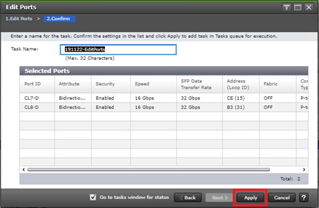
Configure VSP G370 MCU/RCU Port Attributes
MCU and RCU ports between systems in replication carry production data to each VSP controller at DC1 or DC2. To configure the MCU and RCU fibre channel ports for the VSP G370 storage system, follow these steps:
1. Log into Hitachi Storage Navigator.

2. From the left Explorer pane, select the Storage Systems tab.
3. Expand the storage system being configured. Highlight the Ports/Host Groups/iSCSI Targets element in the navigation tree, then click the Ports tab in the main configuration pane.

4. Select the checkboxes for the ports being used for MCU/RCU replication, then click Edit Ports to instantiate the Edit Ports dialog box.
5. Select checkboxes to edit the following settings to modify the selected ports:
a. Port Security: Disabled
b. Port Speed: Auto
c. Fabric: OFF
d. Connection Type: P-to-P
6. Example ports used as MCU/RCU ports between VSP 5100 and VSP G370 in this design are listed in Table 14 .
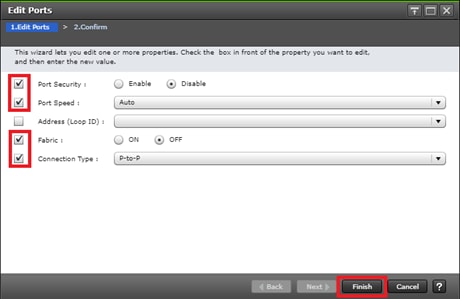
7. Click OK for any warning that appears.
8. Click Finish.
9. Review the changes to be made and check the Go to tasks window for status box, then click Apply.
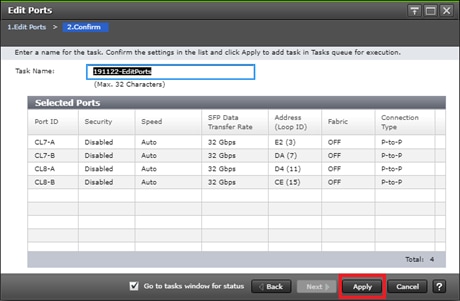
Configure VSP G370 GAD Port attributes
There are specific ports for the GAD storage allocation on DC2 VSP G370. The attributes for the ports used for GAD provisioning have different settings compared to MCU/RCU. To define the GAD port attributes on the VSP G370, follow these steps:
1. Log into Hitachi Storage Navigator.

2. From the left Explorer pane, select the Storage Systems tab.
3. Expand the storage system being configured. Highlight the Ports/Host Groups/iSCSI Targets element in the navigation tree, then click the Ports tab in the main configuration pane.
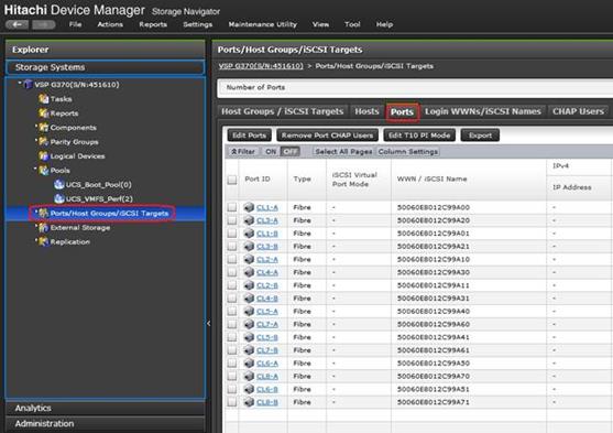
4. Select the checkboxes for the ports being used for MCU/RCU replication, then click Edit Ports to instantiate the Edit Ports dialog box.
5. Select checkboxes to edit the following settings to modify the selected ports:
a. Port Security: Enabled
b. Port Speed: Auto
c. Fabric: ON
d. Connection Type: P-to-P
6. Example ports used as GAD ports between VSP 5100 and VSP G370 in this design are listed in Table 14 .
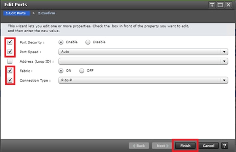
7. Click OK for any warning that appears.
8. Click Finish.
9. Review the changes to be made and check the Go to tasks window for status box, then click Apply.
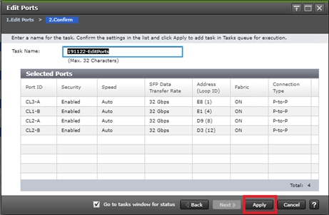
Configure VSP G370 Quorum Port Attributes
The attributes for the ports used for the Quorum disk allocation have specific settings when compared to MCU/RCU and GAD/non-GAD ports. To define Quorum port attributes, follow these steps:
1. Log into Hitachi Storage Navigator.

2. From the left Explorer pane, select the Storage Systems tab.
3. Expand the storage system being configured. Highlight the Ports/Host Groups/iSCSI Targets element in the navigation tree, then click the Ports tab in the main configuration pane.
4. Select the checkboxes for the ports being used for MCU/RCU replication, then click Edit Ports to instantiate the Edit Ports dialog box.
5. Select checkboxes to edit the following settings to modify the selected ports:
a. Port Security: Enabled
b. Port Speed: 16GB
c. Fabric: OFF
d. Connection Type: P-to-P
6. Example ports used as Quorum ports between VSP G1500 and VSP G370 in this design are listed in Table 15 .
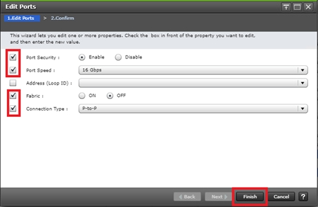
7. Click OK for any warning that appears.
8. Click Finish.
9. Review the changes to be made and check the Go to tasks window for status box, then click Apply.
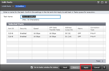
Configure VSP G1500 Quorum Port Attributes
The attributes for the ports used for the Quorum disk LUN needs to be modified prior to the LUN presentation. To define Quorum port attributes, follow these steps:
1. Navigate to the SVP IP of the VSP G1500 and log into Hitachi Storage Navigator.

2. From the left Explorer pane, select the Storage Systems tab.
3. Expand the storage system being configured. Highlight the Ports/Host Groups/iSCSI Targets element in the navigation tree, then click the Ports tab in the main configuration pane.
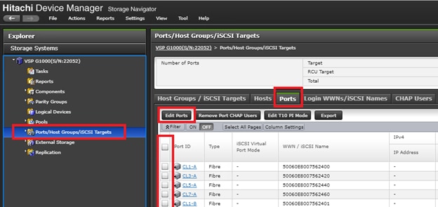
4. Select the checkboxes for the ports being used for MCU/RCU replication, then click Edit Ports to instantiate the Edit Ports dialog box.
5. Select checkboxes to edit the following settings to modify the selected ports:
a. Attribute: Target
b. Port Security: Disabled
c. Port Speed: 16GB
d. Fabric: OFF
e. Connection Type: P-to-P
6. Example ports used as Quorum ports between VSP G1500 and VSP G370 in this design are listed in Table 15 .
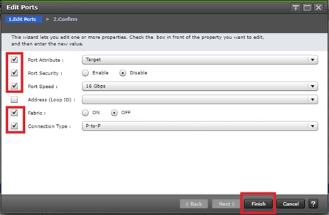
7. Click OK for any warning that appears.
8. Click Finish.
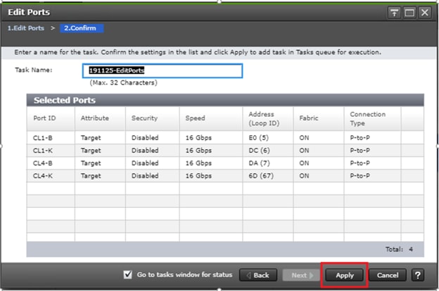
9. Review the changes to be made and check the Go to tasks window for status box, then click Apply.
Quorum Host Group Settings on VSP G1500
Individual host groups are used on each physical fibre channel port on the VSP for each HBA utilized for allocating quorum disk. Make sure you have documented the specific ports on each VSP, their WWNs, and each HBA WWPN before you proceed with this section and ensure that all initiators are displayed as logged into the their VSP fibre channel ports. The following host groups will contain the quorum LUNs for the GAD pair.
To check the initiator logins and to define host groups that are used for quorum disks, follow these steps:
1. Navigate to the SVP IP address, and login to Storage Navigator.
2. From the navigation tree, select Ports/Host Groups/iSCSI Targets.
3. Select the Login WWNs/iSCSI Names tab.
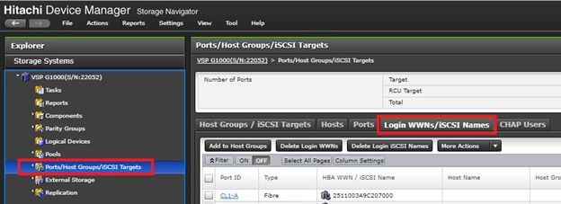
4. Review the list of WWNs and associated ports. You should be able to see each HBA WWN login respective of the VSP 5100 and VSP G370 being direct connected to the VSP G1500 system.
5. With the Ports/Host Groups/iSCSI Targets element in the navigation tree still selected, click the Host Groups/iSCSI Targets tab.
6. Locate the default host groups for the ports you are utilizing your quorum connections. With the ports CL1-K, CL1-B, CL4-K, and CL4-B, the default host groups names are 1K-G00, 1B-G00, 4B-G00, and 4K-G00.
7. Check the box for the default host group and from the actions drop-down list select Edit Host Groups.
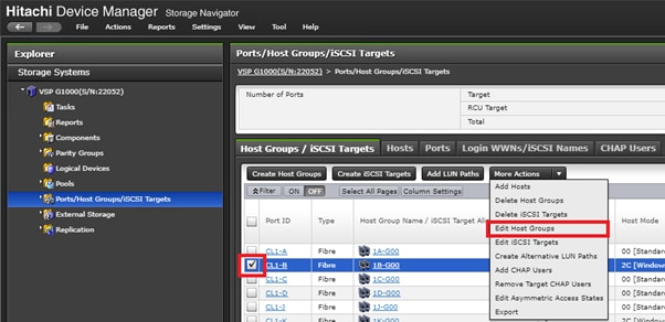
8. From the host mode drop-down list, apply host mode 2C [Windows Extension]. Click Finish.
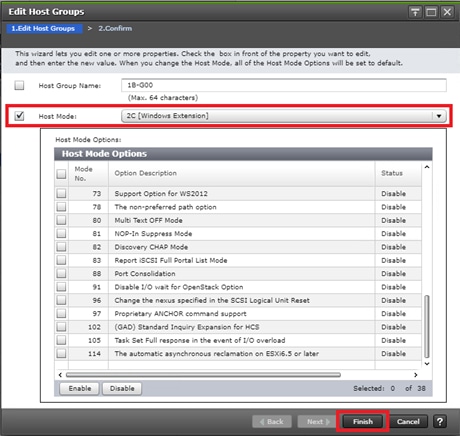
9. Confirm host group settings and click Apply.
10. Repeat steps 6-9 for the remaining quorum ports.
Allocate a Quorum Disk from the VSP G1500
Prior to creating a GAD pair, you must allocate a quorum disk to the primary and secondary system for replication. Prior to allocating a quorum disk you must have laid out physical connections, defined the correct port settings on the VSP G1500, and have modified the default host groups with the correct Windows host mode options. Refer to the previous sections Configure VSP G1500 Quorum Port Attributes and Quorum Host Group Settings on VSP G1500.
![]() A Hitachi Dynamic Provisioning pool must be created prior to creating a Quorum disk. Refer to Create a Hitachi Dynamic Provisioning Pool for Cisco UCS Server Boot LDEVs for DC1 VSP 5100 for HDP pool creation.
A Hitachi Dynamic Provisioning pool must be created prior to creating a Quorum disk. Refer to Create a Hitachi Dynamic Provisioning Pool for Cisco UCS Server Boot LDEVs for DC1 VSP 5100 for HDP pool creation.
To allocate a quorum Disk, follow these steps:
1. Navigate to the SVP IP address and login to Storage Navigator.
2. From the left navigation tree, expand on Pools and click an available pool.
3. Click the Virtual Volumes tab.
4. Select Create LDEVs.
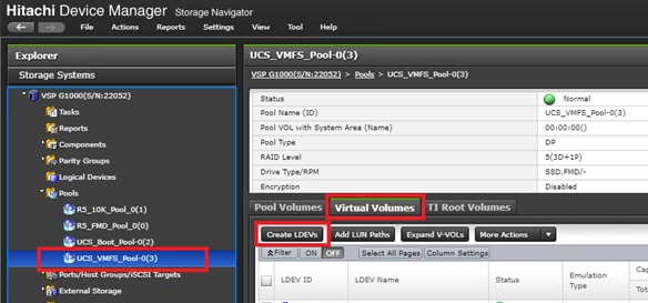
5. Modify the following within the Create LDEVs dialog:
a. LDEV Capacity: Enter the capacity of 20GB.
b. Number of LDEVs: 1
c. LDEV Name: Provide a descriptive name and numeric identifier for the Quorum LDEV.
6. Click Add and verify that the boot LDEV is listed in the right-hand Selected LDEVs pane, then click Next.
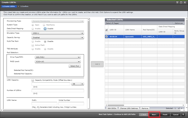
7. The Select LDEVs screen shows the selected LDEVs to which the paths will be added. Ensure the newly created boot LDEV is the only LDEV in the Selected LDEVs pane, then click Next.
8. Click Filter, then create an Attribute/Value filter:
a. Host Group Name
b. Using “Contains” as a qualifier
c. Value which contains text <G00>
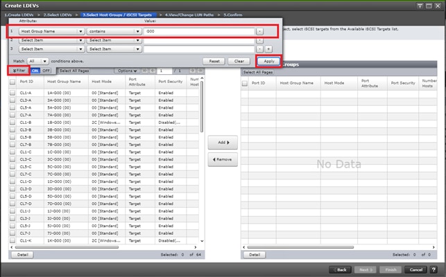
9. Click Apply.
10. Click Filter to hide the filter rules dialog box.
11. Click the Host Mode column to sort in descending order. Host Groups with Host Mode extension 2C will be at the top of your list.
12. Select your quorum Host Groups with extension 2C and click Add.
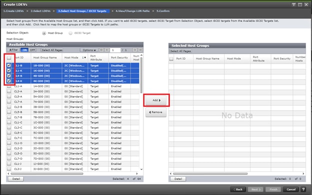
13. Click Next.
14. The View/Change LUN Paths screen shows the LDEV you are adding paths to and the associated host LUN ID that will be presented to the host on a per path basis.
15. Use the scrollbar at the bottom of this screen to review the LUN ID assigned and ensure that all LUN IDs are set to a consistent ID, then click Finish.
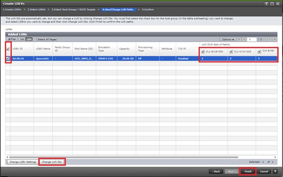
16. Review the LDEV details and LUN ID configuration of the quorum Disk being created, then click Apply to create the LDEV and add paths.
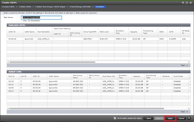
Onboard Quorum Disk to VSP 5100
Once a quorum disk is allocated from the third system, you must onboard the external path groups to the MCU system, as well as virtualize the disk presented as the quorum behind the VSP 5100. To add external paths and virtualize the quorum disk, follow these steps:
1. Log into Hitachi Storage Navigator.
2. From the left Explorer pane, select the Storage System tab.
3. Expand the storage system being configured. Highlight the External Storage element in the navigation tree, then click the External Storage Systems tab in the main configuration pane.
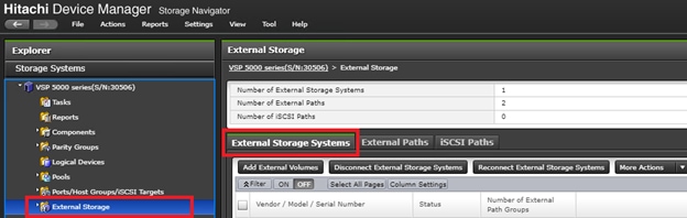
4. From the actions pane, click Add External Volumes.
5. Using the Add External Volumes wizard, click Create External path Group.

6. Within the dialog box, click Discover External Target Ports.
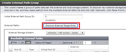
7. In the Discover External Target Ports dialog, select the ports 7D, 8D used for quorum for the VSP 5100 and click Add.
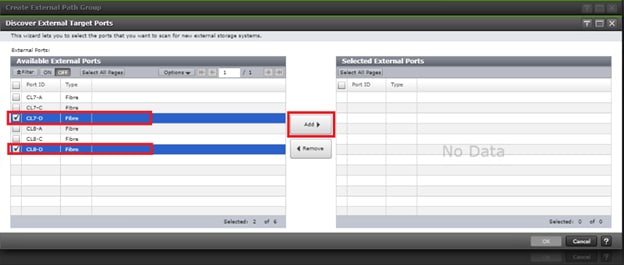
8. Click OK.
9. Using the Create External Path Group wizard, you will now see your available External Paths listed. Select your paths and click Add.
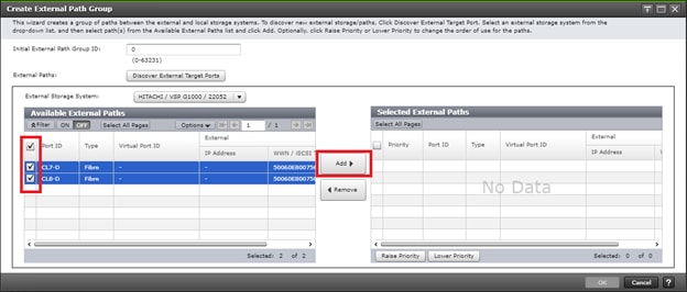
10. Click OK to finalize your external paths.
11. In the Add External Volumes wizard you will see your External Path Group ID, click Next.
12. Under Discovered External Volumes, select your presented quorum disk with applicable LUN ID. Define a LDEV name, click Add.
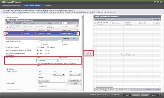
13. Click Finish.
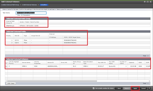
14. Confirm Paths and selected External Volumes and click Apply.
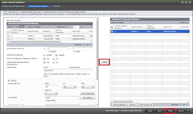
15. Wait until the task is completed before moving onto the next step.
16. When the quorum disk is virtualized, expand the storage system navigation tree and select Remote Connections.
17. Select the Quorum Disks tab.
18. Click Add Quorum Disks.
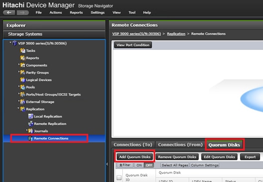
19. Within the Add Quorum Disks dialog box, select your virtualized Quorum disk. Click Add.

20. Click Finish.
21. Click Apply to finalize your quorum disk.
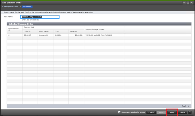
Onboard Quorum Disk to VSP G370
When a quorum disk is allocated from the third system, you must onboard the external path groups to the RCU system, as well as virtualize the disk presented as the quorum behind the VSP G370. To add external paths and virtualize the quorum disk, follow these steps:
1. Log into Hitachi Storage Navigator.
2. From the left Explorer pane, select the Storage System tab.
3. Expand the storage system being configured. Highlight the External Storage element in the navigation tree, then click the External Storage Systems tab in the main configuration pane.
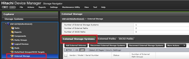
4. From the actions pane, click Add External Volumes.
5. In the Add External Volumes wizard, click Create External path Group.
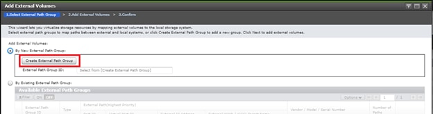
6. Within the dialog box, Click Discover External Target Ports.
7. With Discover External Target Ports dialog, select ports 5B, 6B used for quorum connections for the VSP G370, click Add.
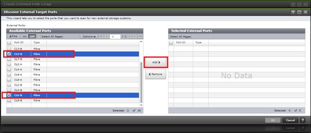
8. Click OK.
9. In the Create External Path Group wizard, you will now see your available External Paths listed. Select your paths and click Add.
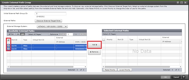
10. Click OK to finalize your external paths.
11. In the Add External Volumes wizard you will now see your External Path Group ID, click Next.
12. Under Discovered External Volumes, select your presented Quorum disk with applicable LUN ID. Define a LDEV name, click Add.
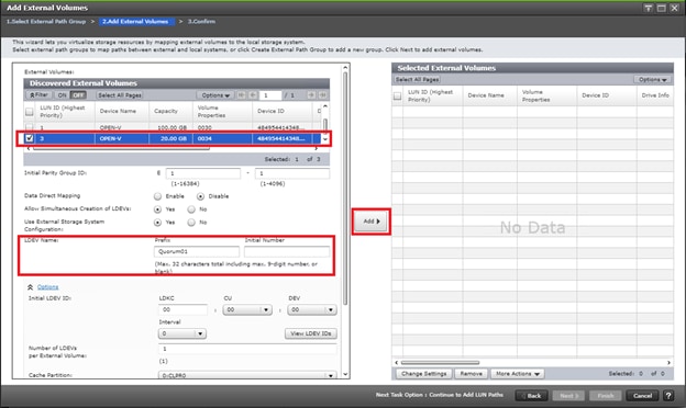
13. Click Finish.
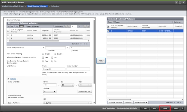
14. Confirm Paths and selected External Volumes, click Apply.
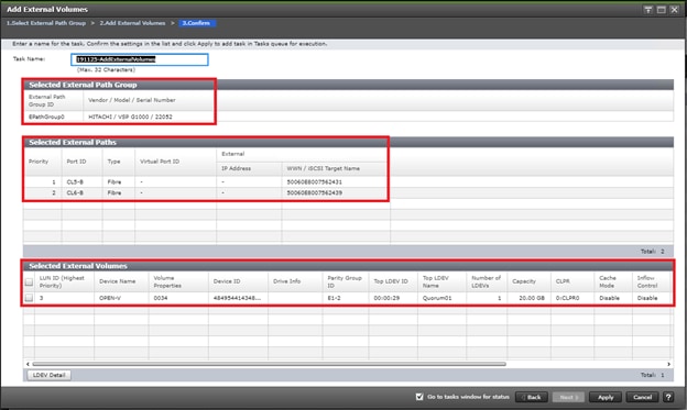
15. Wait until the task is completed before moving onto next step.
16. Once quorum disk is virtualized, expand the storage system navigation tree, select Remote Connections.
17. Select the Quorum Disks tab.
18. Click Add Quorum Disks.
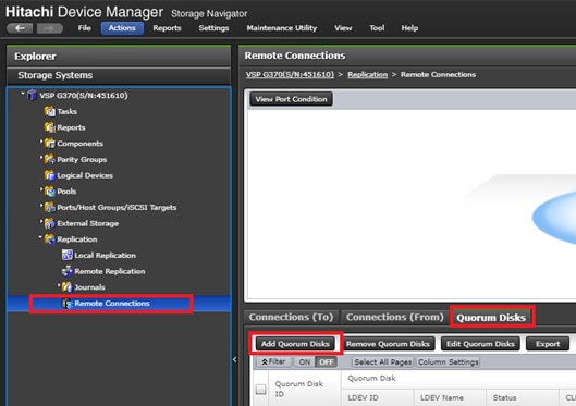
19. Within the Add Quorum Disks dialog box, select your virtualized quorum disk. Click Add.
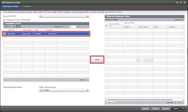
20. Click Finish.
21. Click Apply to finalize your quorum disk.
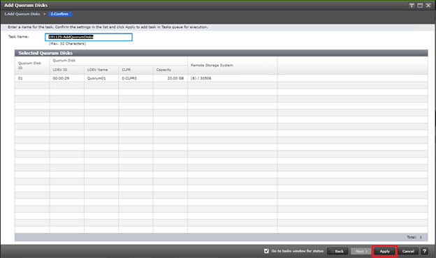
Create a VSM on VSP 5100
When you have completed the physical cabling, port configuration, and created your Pair Management Server, you can create a VSM that is used as a virtual container for common resources between two separate VSP systems. To create your VSM you must use CCI RAIDCOM to communicate with each storage system. Make sure all steps in section Deploying a Pair Management Server is completed and that you can start and communicate with your respective VSP system using CCI.
![]() Using the following command, you are emulating a common VSP between your primary VSP 5100 and secondary VSP G370 with a serial number of 455555. Model type M850S2 is the emulation key for the VSP G370 among VSP systems.
Using the following command, you are emulating a common VSP between your primary VSP 5100 and secondary VSP G370 with a serial number of 455555. Model type M850S2 is the emulation key for the VSP G370 among VSP systems.
To create a VSM on the VSP 5100, run this command using CCI RAIDCOM:
raidcom add resource -resource_name G370_GAD_VSM -virtual_type 455555 M850S2 -IH10
To verify the creation of your VSM, follow these steps:
1. Log into Hitachi Storage Navigator for your respective VSP 5100.
2. Expand Administration in the navigation tree.
3. Click Resource Groups.
4. Verify that VSM G370_GAD_VSM is created.
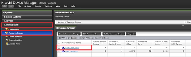
Create a VSM on VSP G370
When you have completed the physical cabling, port configuration, and created your Pair Management Server, you can create a VSM that is used as a virtual container for common resources between two separate VSP systems. To create your VSM, you must use CCI RAIDCOM to communicate with each respective storage system. Make sure all steps in section Deploying a Pair Management Server is completed and that you can start and communicate with your respective VSP system using CCI.
To create a VSM on the VSP G370, run this command using CCI RAIDCOM:
raidcom add resource -resource_name G370_GAD_VSM -virtual_type 455555 M850S2 -IH11
To verify the creation of your VSM, follow these steps:
1. Log into Hitachi Storage Navigator for your respective VSP G370.
2. Expand on Administration on the left-hand navigation tree.
3. Click Resource Groups.
4. Verify that VSM G370_GAD_VSM is created.
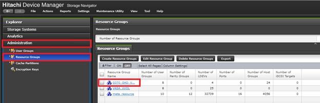
Create Remote Connections between VSP 5100 and VSP G370 using CCI
When you have laid out physical connections between the primary VSP 5100 and secondary VSP G370 system, you must create a logical connection based off the ports connecting MCU and RCU system for replication. Confirm you can communication with your respective systems using CCI prior to running the following commands.
To create the MCU/RCU connections run the following commands using CCI RAIDCOM:
Add VSP 5100->VSP G370 MCU->RCU replication path:
raidcom add rcu -cu_free 451610 M800 0 -mcu_port CL7-A -rcu_port CL8-A -IH10
raidcom get command_status -IH10
Add secondary VSP 5100-> VSP G370 MCU->RCU replication path:
raidcom add rcu_path -cu_free 451610 M800 0 -mcu_port CL8-A -rcu_port CL7-A -IH10
raidcom get command_status -IH10
Add VSP G370-> VSP 5100 MCU->RCU replication path:
raidcom add rcu -cu_free 530506 R900F 0 -mcu_port CL8-B -rcu_port CL7-C -IH11
raidcom get command_status -IH11
Add secondary VSP G370->VSP 5100 MCU->RCU replication path:
raidcom add rcu_path -cu_free 530506 R900F 0 -mcu_port CL7-B -rcu_port CL8-C -IH11
raidcom get command_status -IH11
Check status of all remote replication paths:
raidcom get rcu -cu_free 451610 M800 0 -IH10
raidcom get rcu -cu_free 530506 R900F 0 -IH11
Deploy Hitachi GAD with RAIDCOM
Make sure that all physical cabling is laid out, all respective VSP port settings applied, and you have created the applicable VSM. All commands provided in this section will be issued from Pair Management Servers at each data center. -IH10 will control the VSP 5100 system from pair management server 1 and -IH11 will control VSP G370 from pair management server 2.
Reserve GAD Host Groups on VSP 5100 VSM using CCI
Prior to creating the GAD pair, you must associate common resources used for GAD within the VSM starting with host groups which will hold GAD volumes for all hosts at DC1.
To reserve GAD host groups on the VSP 5100 to the G370_GAD_VSM, run the following commands using CCI RAIDCOM.
Reserve all necessary Host Groups in the 5100 G370_GAD_VSM, starting at host group ID (HG_ID) 50:
DC1-ESX1 - HG_ID 50
raidcom add resource -resource_name G370_GAD_VSM -port CL1-B-50 -IH10
raidcom add resource -resource_name G370_GAD_VSM -port CL1-D-50 -IH10
raidcom add resource -resource_name G370_GAD_VSM -port CL2-B-50 -IH10
raidcom add resource -resource_name G370_GAD_VSM -port CL2-D-50 -IH10
DC1-ESX2 - HG_ID 51
raidcom add resource -resource_name G370_GAD_VSM -port CL1-B-51 -IH10
raidcom add resource -resource_name G370_GAD_VSM -port CL1-D-51 -IH10
raidcom add resource -resource_name G370_GAD_VSM -port CL2-B-51 -IH10
raidcom add resource -resource_name G370_GAD_VSM -port CL2-D-51 -IH10
DC1-ESX-3 - HG_ID 52
raidcom add resource -resource_name G370_GAD_VSM -port CL1-B-52 -IH10
raidcom add resource -resource_name G370_GAD_VSM -port CL1-D-52 -IH10
raidcom add resource -resource_name G370_GAD_VSM -port CL2-B-52 -IH10
raidcom add resource -resource_name G370_GAD_VSM -port CL2-D-52 -IH10
DC2-ESX-1 - HG_ID 53
raidcom add resource -resource_name G370_GAD_VSM -port CL1-B-53 -IH10
raidcom add resource -resource_name G370_GAD_VSM -port CL1-D-53 -IH10
raidcom add resource -resource_name G370_GAD_VSM -port CL2-B-53 -IH10
raidcom add resource -resource_name G370_GAD_VSM -port CL2-D-53 -IH10
DC2-ESX-2 - HG_ID 54
raidcom add resource -resource_name G370_GAD_VSM -port CL1-B-54 -IH10
raidcom add resource -resource_name G370_GAD_VSM -port CL1-D-54 -IH10
raidcom add resource -resource_name G370_GAD_VSM -port CL2-B-54 -IH10
raidcom add resource -resource_name G370_GAD_VSM -port CL2-D-54 -IH10
DC2-ESX- 3 - HG_ID 55
raidcom add resource -resource_name G370_GAD_VSM -port CL1-B-55 -IH10
raidcom add resource -resource_name G370_GAD_VSM -port CL1-D-55 -IH10
raidcom add resource -resource_name G370_GAD_VSM -port CL2-B-55 -IH10
raidcom add resource -resource_name G370_GAD_VSM -port CL2-D-55 -IH10
Create and Prepare of Primary Volume on VSP 5100
Before creating a pair, you must prepare the volume that is planned to be used for the primary volume of GAD from the VSP 5100. To create and prepare the primary volume for a GAD pair, issue these steps using CCI RAIDCOM:
Unmap the virtual LDEV ID of the primary volume (P-VOL)
raidcom unmap resource -ldev_id 0x00FF -virtual_ldev_id 0x00FF -IH10
Reserve the LDEV ID in the VSP 5100 VP G370 VSM
raidcom add resource -resource_name G370_GAD_VSM -ldev_id 0x00FF -IH10
Create the dynamic provision (DP) Pool for the PVOL
raidcom add dp_pool -pool_id 100 -pool_name GAD_5100_Pool -ldev_id 0x0009 -IH10
Create the PVOL (1TB in this example - capacity is in blocks)
raidcom add ldev -pool 100 -ldev_id 0x00FF -capacity 2147483648 -IH10
Enable ALUA mode for the PVOL, required for cross pathing between data centers
raidcom modify ldev -ldev_id 0x00FF -alua enable -IH10
Remap the virtual LDEV ID of the PVOL
raidcom map resource -ldev_id 0x00FF -virtual_ldev_id 0x00FF -IH10
Create GAD Host Groups at DC1 on VSP 5100 and Set Host Mode Options
Dedicated host groups solely for GAD provisioning will also need to be modified respectively on the VSP 5100. Prior to issuing the below commands confirm you have created the VSM and have reserved GAD host groups. Host mode options (HMOs) 54, 63, and 114 must be enabled.
Issue the following commands using CCI RAIDCOM to apply the names and applicable host mode options to your host groups:
DC1- ESX1 - HG_ID 50
raidcom add host_grp -port CL1-B-50 -host_grp_name DC1_ESX-1-Local_GAD_Fab_A -IH10
raidcom add host_grp -port CL1-D-50 -host_grp_name DC1_ESX-1-Local_GAD_Fab_B -IH10
raidcom add host_grp -port CL2-B-50 -host_grp_name DC1_ESX-1-Local_GAD_Fab_A -IH10
raidcom add host_grp -port CL2-D-50 -host_grp_name DC1_ESX-1-Local_GAD_Fab_B -IH10
raidcom modify host_grp -port CL1-B-50 -host_mode VMWARE_EX -set_host_mode_opt 54 63 114 -IH10
raidcom modify host_grp -port CL1-D-50 -host_mode VMWARE_EX -set_host_mode_opt 54 63 114 -IH10
raidcom modify host_grp -port CL2-B-50 -host_mode VMWARE_EX -set_host_mode_opt 54 63 114 -IH10
raidcom modify host_grp -port CL2-D-50 -host_mode VMWARE_EX -set_host_mode_opt 54 63 114 -IH10
DC1-ESX-2 - HG_ID 51
raidcom add host_grp -port CL1-B-51 -host_grp_name DC1_ESX-2-Local_GAD_Fab_A -IH10
raidcom add host_grp -port CL1-D-51 -host_grp_name DC1_ESX-2-Local_GAD_Fab_B -IH10
raidcom add host_grp -port CL2-B-51 -host_grp_name DC1_ESX-2-Local_GAD_Fab_A -IH10
raidcom add host_grp -port CL2-D-51 -host_grp_name DC1_ESX-2-Local_GAD_Fab_B -IH10
raidcom modify host_grp -port CL1-B-51 -host_mode VMWARE_EX -set_host_mode_opt 54 63 114 -IH10
raidcom modify host_grp -port CL1-D-51 -host_mode VMWARE_EX -set_host_mode_opt 54 63 114 -IH10
raidcom modify host_grp -port CL2-B-51 -host_mode VMWARE_EX -set_host_mode_opt 54 63 114 -IH10
raidcom modify host_grp -port CL2-D-51 -host_mode VMWARE_EX -set_host_mode_opt 54 63 114 -IH10
DC-1 ESX-3 - HG_ID 52
raidcom add host_grp -port CL1-B-52 -host_grp_name DC1_ESX-3-Local_GAD_Fab_A -IH10
raidcom add host_grp -port CL1-D-52 -host_grp_name DC1_ESX-3-Local_GAD_Fab_B -IH10
raidcom add host_grp -port CL2-B-52 -host_grp_name DC1_ESX-3-Local_GAD_Fab_A -IH10
raidcom add host_grp -port CL2-D-52 -host_grp_name DC1_ESX-3-Local_GAD_Fab_B -IH10
raidcom modify host_grp -port CL1-B-52 -host_mode VMWARE_EX -set_host_mode_opt 54 63 114 -IH10
raidcom modify host_grp -port CL1-D-52 -host_mode VMWARE_EX -set_host_mode_opt 54 63 114 -IH10
raidcom modify host_grp -port CL2-B-52 -host_mode VMWARE_EX -set_host_mode_opt 54 63 114 -IH10
raidcom modify host_grp -port CL2-D-52 -host_mode VMWARE_EX -set_host_mode_opt 54 63 114 -IH10
DC2-ESX-1 - HG_ID 53
raidcom add host_grp -port CL1-B-53 -host_grp_name DC2_ESX-1-Remote_GAD_Fab_A -IH10
raidcom add host_grp -port CL1-D-53 -host_grp_name DC2_ESX-1-Remote_GAD_Fab_B -IH10
raidcom add host_grp -port CL2-B-53 -host_grp_name DC2_ESX-1-Remote_GAD_Fab_A -IH10
raidcom add host_grp -port CL2-D-53 -host_grp_name DC2_ESX-1-Remote_GAD_Fab_B -IH10
raidcom modify host_grp -port CL1-B-53 -host_mode VMWARE_EX -set_host_mode_opt 54 63 114 -IH10
raidcom modify host_grp -port CL1-D-53 -host_mode VMWARE_EX -set_host_mode_opt 54 63 114 -IH10
raidcom modify host_grp -port CL2-B-53 -host_mode VMWARE_EX -set_host_mode_opt 54 63 114 -IH10
raidcom modify host_grp -port CL2-D-53 -host_mode VMWARE_EX -set_host_mode_opt 54 63 114 -IH10
DC-2 ESX-2 - HG_ID 54
raidcom add host_grp -port CL1-B-54 -host_grp_name DC2_ESX-2-Remote_GAD_Fab_A -IH10
raidcom add host_grp -port CL1-D-54 -host_grp_name DC2_ESX-2-Remote_GAD_Fab_B -IH10
raidcom add host_grp -port CL2-B-54 -host_grp_name DC2_ESX-2-Remote_GAD_Fab_A -IH10
raidcom add host_grp -port CL2-D-54 -host_grp_name DC2_ESX-2-Remote_GAD_Fab_B -IH10
raidcom modify host_grp -port CL1-B-54 -host_mode VMWARE_EX -set_host_mode_opt 54 63 114 -IH10
raidcom modify host_grp -port CL1-D-54 -host_mode VMWARE_EX -set_host_mode_opt 54 63 114 -IH10
raidcom modify host_grp -port CL2-B-54 -host_mode VMWARE_EX -set_host_mode_opt 54 63 114 -IH10
raidcom modify host_grp -port CL2-D-54 -host_mode VMWARE_EX -set_host_mode_opt 54 63 114 -IH10
DC-2 ESX-3 -HG_ID 55
raidcom add host_grp -port CL1-B-55 -host_grp_name DC2_ESX-3-Remote_GAD_Fab_A -IH10
raidcom add host_grp -port CL1-D-55 -host_grp_name DC2_ESX-3-Remote_GAD_Fab_B -IH10
raidcom add host_grp -port CL2-B-55 -host_grp_name DC2_ESX-3-Remote_GAD_Fab_A -IH10
raidcom add host_grp -port CL2-D-55 -host_grp_name DC2_ESX-3-Remote_GAD_Fab_B -IH10
raidcom modify host_grp -port CL1-B-55 -host_mode VMWARE_EX -set_host_mode_opt 54 63 114 -IH10
raidcom modify host_grp -port CL1-D-55 -host_mode VMWARE_EX -set_host_mode_opt 54 63 114 -IH10
raidcom modify host_grp -port CL2-B-55 -host_mode VMWARE_EX -set_host_mode_opt 54 63 114 -IH10
raidcom modify host_grp -port CL2-D-55 -host_mode VMWARE_EX -set_host_mode_opt 54 63 114 -IH10
Add LUN Paths to VSP 5100 GAD Primary Volume
When you have prepped the primary system for GAD pair creation, you can map your primary volume to your respective GAD host groups. To allocate your VSP 5100 primary volume to GAD host groups, issue the following commands via RAIDCOM CCI. Add the LUN paths to all of the Host Groups with LUN ID 100.
DC1-ESX1 - HG_ID 50
raidcom add lun -port CL1-B-50 -lun_id 100 -ldev_id 0x00FF -IH10
raidcom add lun -port CL1-D-50 -lun_id 100 -ldev_id 0x00FF -IH10
raidcom add lun -port CL2-B-50 -lun_id 100 -ldev_id 0x00FF -IH10
raidcom add lun -port CL2-D-50 -lun_id 100 -ldev_id 0x00FF -IH10
DC1 ESX2 – HG_ID 51
raidcom add lun -port CL1-B-51 -lun_id 100 -ldev_id 0x00FF -IH10
raidcom add lun -port CL1-D-51 -lun_id 100 -ldev_id 0x00FF -IH10
raidcom add lun -port CL2-B-51 -lun_id 100 -ldev_id 0x00FF -IH10
raidcom add lun -port CL2-D-51 -lun_id 100 -ldev_id 0x00FF -IH10
DC1 ESX3 – HG_ID 52
raidcom add lun -port CL1-B-52 -lun_id 100 -ldev_id 0x00FF -IH10
raidcom add lun -port CL1-D-52 -lun_id 100 -ldev_id 0x00FF -IH10
raidcom add lun -port CL2-B-52 -lun_id 100 -ldev_id 0x00FF -IH10
raidcom add lun -port CL2-D-52 -lun_id 100 -ldev_id 0x00FF -IH10
DC2 ESX1 – HG_ID 53
raidcom add lun -port CL1-B-53 -lun_id 100 -ldev_id 0x00FF -IH10
raidcom add lun -port CL1-D-53 -lun_id 100 -ldev_id 0x00FF -IH10
raidcom add lun -port CL2-B-53 -lun_id 100 -ldev_id 0x00FF -IH10
raidcom add lun -port CL2-D-53 -lun_id 100 -ldev_id 0x00FF -IH10
DC2 ESX2 – HG_ID 54
raidcom add lun -port CL1-B-54 -lun_id 100 -ldev_id 0x00FF -IH10
raidcom add lun -port CL1-D-54 -lun_id 100 -ldev_id 0x00FF -IH10
raidcom add lun -port CL2-B-54 -lun_id 100 -ldev_id 0x00FF -IH10
raidcom add lun -port CL2-D-54 -lun_id 100 -ldev_id 0x00FF -IH10
DC2 ESX3 – HG_ID 55
raidcom add lun -port CL1-B-55 -lun_id 100 -ldev_id 0x00FF -IH10
raidcom add lun -port CL1-D-55 -lun_id 100 -ldev_id 0x00FF -IH10
raidcom add lun -port CL2-B-55 -lun_id 100 -ldev_id 0x00FF -IH10
raidcom add lun -port CL2-D-55 -lun_id 100 -ldev_id 0x00FF -IH10
Set Non-optimized Asymmetric Logical Unit Access (ALUA) Mode for DC2 Remote Host Groups on VSP 5100
When you have created and mapped your GAD volume to your local GAD host groups for DC1 hosts on the VSP 5100, you will need to set ALUA to host groups which host the non-optimized paths for DC2 hosts. Issue the following commands via CCI RAIDCOM on remote host groups on the VSP 5100.
DC-2 ESX1 - HG_ID 53
raidcom modify lun -port CL1-B-53 -lun_id all -asymmetric_access_state non_optimized -IH10
raidcom modify lun -port CL1-D-53 -lun_id all -asymmetric_access_state non_optimized -IH10
raidcom modify lun -port CL2-B-53 -lun_id all -asymmetric_access_state non_optimized -IH10
raidcom modify lun -port CL2-D-53 -lun_id all -asymmetric_access_state non_optimized -IH10
DC-2 ESX2 – HG_ID 54
raidcom modify lun -port CL1-B-54 -lun_id all -asymmetric_access_state non_optimized -IH10
raidcom modify lun -port CL1-D-54 -lun_id all -asymmetric_access_state non_optimized -IH10
raidcom modify lun -port CL2-B-54 -lun_id all -asymmetric_access_state non_optimized -IH10
raidcom modify lun -port CL2-D-54 -lun_id all -asymmetric_access_state non_optimized -IH10
DC-2 ESX3 -HG_ID 55
raidcom modify lun -port CL1-B-55 -lun_id all -asymmetric_access_state non_optimized -IH10
raidcom modify lun -port CL1-D-55 -lun_id all -asymmetric_access_state non_optimized -IH10
raidcom modify lun -port CL2-B-55 -lun_id all -asymmetric_access_state non_optimized -IH10
raidcom modify lun -port CL2-D-55 -lun_id all -asymmetric_access_state non_optimized -IH10
Reserve GAD Host Groups on VSP G370 VSM using CCI
Prior to creating your GAD pair, you must associate common resources within the VSM stating with host groups for all hosts at DC2.
To reserve GAD host groups on the VSP G370 to the G370_GAD_VSM, issue the following commands using CCI RAIDCOM.
Reserve all the necessary Host Groups in the VSP G370 G370_GAD_VSM, starting at HG_ID 50:
DC1-ESX1 - HG_ID 50
raidcom add resource -resource_name G370_GAD_VSM -port CL3-A-50 -IH11
raidcom add resource -resource_name G370_GAD_VSM -port CL1-B-50 -IH11
raidcom add resource -resource_name G370_GAD_VSM -port CL2-A-50 -IH11
raidcom add resource -resource_name G370_GAD_VSM -port CL4-B-50 -IH11
DC1 ESX 2 - HG_ID 51
raidcom add resource -resource_name G370_GAD_VSM -port CL3-A-51 -IH11
raidcom add resource -resource_name G370_GAD_VSM -port CL1-B-51 -IH11
raidcom add resource -resource_name G370_GAD_VSM -port CL2-A-51 -IH11
raidcom add resource -resource_name G370_GAD_VSM -port CL4-B-51 -IH11
DC1 ESX 3 - HG_ID 52
raidcom add resource -resource_name G370_GAD_VSM -port CL3-A-52 -IH11
raidcom add resource -resource_name G370_GAD_VSM -port CL1-B-52 -IH11
raidcom add resource -resource_name G370_GAD_VSM -port CL2-A-52 -IH11
raidcom add resource -resource_name G370_GAD_VSM -port CL4-B-52 -IH11
DC-2 ESX 1 - HG_ID 53
raidcom add resource -resource_name G370_GAD_VSM -port CL3-A-53 -IH11
raidcom add resource -resource_name G370_GAD_VSM -port CL1-B-53 -IH11
raidcom add resource -resource_name G370_GAD_VSM -port CL2-A-53 -IH11
raidcom add resource -resource_name G370_GAD_VSM -port CL4-B-53 -IH11
DC2 ESX 2 - HG_ID 54
raidcom add resource -resource_name G370_GAD_VSM -port CL3-A-54 -IH11
raidcom add resource -resource_name G370_GAD_VSM -port CL1-B-54 -IH11
raidcom add resource -resource_name G370_GAD_VSM -port CL2-A-54 -IH11
raidcom add resource -resource_name G370_GAD_VSM -port CL4-B-54 -IH11
DC2 ESX 3 -HG_ID 55
raidcom add resource -resource_name G370_GAD_VSM -port CL3-A-55 -IH11
raidcom add resource -resource_name G370_GAD_VSM -port CL1-B-55 -IH11
raidcom add resource -resource_name G370_GAD_VSM -port CL2-A-55 -IH11
raidcom add resource -resource_name G370_GAD_VSM -port CL4-B-55 -IH11
Create and Prepare of Secondary Volume on VSP G370
Before creating a pair, you must prep the volume that is planned on being used for GAD from the VSP G370. To create and prepare the secondary volume for a GAD pair on VSP G370, issue these steps via CCI RAIDCOM:
Unmap the virtual LDEV ID of the secondary volume (S-VOL)
raidcom unmap resource -ldev_id 0x00EE -virtual_ldev_id 0x00EE -IH11
Reserve the LDEV ID of the SVOL in the VSP G370 G370_GAD_VSM
raidcom add resource -resource_name G370_GAD_VSM -ldev_id 0x00EE -IH11
Set the GAD reserve bit on the SVOL LDEV ID
raidcom map resource -ldev_id 0x00EE -virtual_ldev_id reserve -IH11
Create the dynamic provision (DP) Pool for the S-VOL
raidcom add dp_pool -pool_id 50 -pool_name GAD_370_Pool -ldev_id 0x0007 -IH11
Create the SVOL (1TB in this example - capacity is in blocks)
raidcom add ldev -pool 50 -ldev_id 0x00EE -capacity 2147483648 -IH11
Unmap the virtual LDEV ID of the Planned GAD pair (PVOL Virtual LDEV ID)
raidcom unmap resource -ldev_id 0x00FF -virtual_ldev_id 0x00FF -IH11
Create Host Groups in DC2 on VSP G370 and Set Host Mode Options
Dedicated host groups solely for GAD provisioning will also need to be modified on the VSP G370. Prior to issuing the following commands, confirm you have created the VSM and have reserved GAD host groups. Host mode options (HMOs) 54, 63, and 114 must be enabled.
Issue the following commands via CCI RAIDCOM to apply respective names and applicable host mode options:
DC-1 ESX1 - HG_ID 50
raidcom add host_grp -port CL3-A-50 -host_grp_name DC1_ESX-1-Remote_GAD_Fab_A -IH11
raidcom add host_grp -port CL1-B-50 -host_grp_name DC1_ESX-1-Remote_GAD_Fab_B -IH11
raidcom add host_grp -port CL2-A-50 -host_grp_name DC1_ESX-1-Remote_GAD_Fab_A -IH11
raidcom add host_grp -port CL4-B-50 -host_grp_name DC1_ESX-1-Remote_GAD_Fab_B -IH11
raidcom modify host_grp -port CL3-A-50 -host_mode VMWARE_EX -set_host_mode_opt 54 63 114 -IH11
raidcom modify host_grp -port CL1-B-50 -host_mode VMWARE_EX -set_host_mode_opt 54 63 114 -IH11
raidcom modify host_grp -port CL2-A-50 -host_mode VMWARE_EX -set_host_mode_opt 54 63 114 -IH11
raidcom modify host_grp -port CL4-B-50 -host_mode VMWARE_EX -set_host_mode_opt 54 63 114 -IH11
DC-1 ESX2 - HG_ID 51
raidcom add host_grp -port CL3-A-51 -host_grp_name DC1_ESX-2-Remote_GAD_Fab_A -IH11
raidcom add host_grp -port CL1-B-51 -host_grp_name DC1_ESX-2-Remote_GAD_Fab_B -IH11
raidcom add host_grp -port CL2-A-51 -host_grp_name DC1_ESX-2-Remote_GAD_Fab_A -IH11
raidcom add host_grp -port CL4-B-51 -host_grp_name DC1_ESX-2-Remote_GAD_Fab_B -IH11
raidcom modify host_grp -port CL3-A-51 -host_mode VMWARE_EX -set_host_mode_opt 54 63 114 -IH11
raidcom modify host_grp -port CL1-B-51 -host_mode VMWARE_EX -set_host_mode_opt 54 63 114 -IH11
raidcom modify host_grp -port CL2-A-51 -host_mode VMWARE_EX -set_host_mode_opt 54 63 114 -IH11
raidcom modify host_grp -port CL4-B-51 -host_mode VMWARE_EX -set_host_mode_opt 54 63 114 -IH11
DC-1 ESX3 -HG_ID 52
raidcom add host_grp -port CL3-A-52 -host_grp_name DC1_ESX-3-Remote_GAD_Fab_A -IH11
raidcom add host_grp -port CL1-B-52 -host_grp_name DC1_ESX-3-Remote_GAD_Fab_B -IH11
raidcom add host_grp -port CL2-A-52 -host_grp_name DC1_ESX-3-Remote_GAD_Fab_A -IH11
raidcom add host_grp -port CL4-B-52 -host_grp_name DC1_ESX-3-Remote_GAD_Fab_B -IH11
raidcom modify host_grp -port CL3-A-52 -host_mode VMWARE_EX -set_host_mode_opt 54 63 114 -IH11
raidcom modify host_grp -port CL1-B-52 -host_mode VMWARE_EX -set_host_mode_opt 54 63 114 -IH11
raidcom modify host_grp -port CL2-A-52 -host_mode VMWARE_EX -set_host_mode_opt 54 63 114 -IH11
raidcom modify host_grp -port CL4-B-52 -host_mode VMWARE_EX -set_host_mode_opt 54 63 114 -IH11
DC-2 ESX1 - HG_ID 53
raidcom add host_grp -port CL3-A-53 -host_grp_name DC2_ESX-1-Local_GAD_Fab_A -IH11
raidcom add host_grp -port CL1-B-53 -host_grp_name DC2_ESX-1-Local_GAD_Fab_B -IH11
raidcom add host_grp -port CL2-A-53 -host_grp_name DC2_ESX-1-Local_GAD_Fab_A -IH11
raidcom add host_grp -port CL4-B-53 -host_grp_name DC2_ESX-1-Local_GAD_Fab_B -IH11
raidcom modify host_grp -port CL3-A-53 -host_mode VMWARE_EX -set_host_mode_opt 54 63 114 -IH11
raidcom modify host_grp -port CL1-B-53 -host_mode VMWARE_EX -set_host_mode_opt 54 63 114 -IH11
raidcom modify host_grp -port CL2-A-53 -host_mode VMWARE_EX -set_host_mode_opt 54 63 114 -IH11
raidcom modify host_grp -port CL4-B-53 -host_mode VMWARE_EX -set_host_mode_opt 54 63 114 -IH11
DC2 ESX2 - HG_ID 54
raidcom add host_grp -port CL3-A-54 -host_grp_name DC2_ESX-2-Local_GAD_Fab_A -IH11
raidcom add host_grp -port CL1-B-54 -host_grp_name DC2_ESX-2-Local_GAD_Fab_B -IH11
raidcom add host_grp -port CL2-A-54 -host_grp_name DC2_ESX-2-Local_GAD_Fab_A -IH11
raidcom add host_grp -port CL4-B-54 -host_grp_name DC2_ESX-2-Local_GAD_Fab_B -IH11
raidcom modify host_grp -port CL3-A-54 -host_mode VMWARE_EX -set_host_mode_opt 54 63 114 -IH11
raidcom modify host_grp -port CL1-B-54 -host_mode VMWARE_EX -set_host_mode_opt 54 63 114 -IH11
raidcom modify host_grp -port CL2-A-54 -host_mode VMWARE_EX -set_host_mode_opt 54 63 114 -IH11
raidcom modify host_grp -port CL4-B-54 -host_mode VMWARE_EX -set_host_mode_opt 54 63 114 -IH11
DC-2 ESX3 -HG_ID 55
raidcom add host_grp -port CL3-A-55 -host_grp_name DC2_ESX-3-Local_GAD_Fab_A -IH11
raidcom add host_grp -port CL1-B-55 -host_grp_name DC2_ESX-3-Local_GAD_Fab_B -IH11
raidcom add host_grp -port CL2-A-55 -host_grp_name DC2_ESX-3-Local_GAD_Fab_A -IH11
raidcom add host_grp -port CL4-B-55 -host_grp_name DC2_ESX-3-Local_GAD_Fab_B -IH11
raidcom modify host_grp -port CL3-A-55 -host_mode VMWARE_EX -set_host_mode_opt 54 63 114 -IH11
raidcom modify host_grp -port CL1-B-55 -host_mode VMWARE_EX -set_host_mode_opt 54 63 114 -IH11
raidcom modify host_grp -port CL2-A-55 -host_mode VMWARE_EX -set_host_mode_opt 54 63 114 -IH11
raidcom modify host_grp -port CL4-B-55 -host_mode VMWARE_EX -set_host_mode_opt 54 63 114 -IH11
Add LUN Paths to VSP 5100 GAD Primary Volume
When you have prepped the primary system for GAD pair creation, you can map your primary volume to your respective GAD host groups. To allocate your volume with LUN ID 100 to GAD host groups, issue the following commands using RAIDCOM CCI.
Add the LUN paths to all of the Host Groups with LUN ID 100:
DC1 ESX1
raidcom add lun -port CL3-A-50 -lun_id 100 -ldev_id 0x00EE -IH11
raidcom add lun -port CL1-B-50 -lun_id 100 -ldev_id 0x00EE -IH11
raidcom add lun -port CL2-A-50 -lun_id 100 -ldev_id 0x00EE -IH11
raidcom add lun -port CL4-B-50 -lun_id 100 -ldev_id 0x00EE -IH11
DC1 ESX2
raidcom add lun -port CL3-A-51 -lun_id 100 -ldev_id 0x00EE -IH11
raidcom add lun -port CL1-B-51 -lun_id 100 -ldev_id 0x00EE -IH11
raidcom add lun -port CL2-A-51 -lun_id 100 -ldev_id 0x00EE -IH11
raidcom add lun -port CL4-B-51 -lun_id 100 -ldev_id 0x00EE -IH11
DC1 ESX3
raidcom add lun -port CL3-A-52 -lun_id 100 -ldev_id 0x00EE -IH11
raidcom add lun -port CL1-B-52 -lun_id 100 -ldev_id 0x00EE -IH11
raidcom add lun -port CL2-A-52 -lun_id 100 -ldev_id 0x00EE -IH11
raidcom add lun -port CL4-B-52 -lun_id 100 -ldev_id 0x00EE -IH11
DC2 ESX1
raidcom add lun -port CL3-A-53 -lun_id 100 -ldev_id 0x00EE -IH11
raidcom add lun -port CL1-B-53 -lun_id 100 -ldev_id 0x00EE -IH11
raidcom add lun -port CL2-A-53 -lun_id 100 -ldev_id 0x00EE -IH11
raidcom add lun -port CL4-B-53 -lun_id 100 -ldev_id 0x00EE -IH11
DC2 ESX2
raidcom add lun -port CL3-A-54 -lun_id 100 -ldev_id 0x00EE -IH11
raidcom add lun -port CL1-B-54 -lun_id 100 -ldev_id 0x00EE -IH11
raidcom add lun -port CL2-A-54 -lun_id 100 -ldev_id 0x00EE -IH11
raidcom add lun -port CL4-B-54 -lun_id 100 -ldev_id 0x00EE -IH11
DC2 ESX3
raidcom add lun -port CL3-A-55 -lun_id 100 -ldev_id 0x00EE -IH11
raidcom add lun -port CL1-B-55 -lun_id 100 -ldev_id 0x00EE -IH11
raidcom add lun -port CL2-A-55 -lun_id 100 -ldev_id 0x00EE -IH11
raidcom add lun -port CL4-B-55 -lun_id 100 -ldev_id 0x00EE -IH11
Set Non-optimized Asymmetric Logical Unit Access (ALUA) Mode for DC1 Remote Host Groups on VSP G370
When you have created and mapped your GAD volume to your local host groups for DC1 hosts on the VSP 5100, you will need to define host groups which host the non-optimized paths for DC2 hosts. Issue the following commands using CCI RAIDCOM on remote host groups on the VSP 5100:
DC-1 ESX 1 HG-ID50
raidcom modify lun -port CL3-A-50 -lun_id all -asymmetric_access_state non_optimized -IH11
raidcom modify lun -port CL1-B-50 -lun_id all -asymmetric_access_state non_optimized -IH11
raidcom modify lun -port CL2-A-50 -lun_id all -asymmetric_access_state non_optimized -IH11
raidcom modify lun -port CL4-B-50 -lun_id all -asymmetric_access_state non_optimized -IH11
DC-1 ESX 2 HG_ID 51
raidcom modify lun -port CL3-A-51 -lun_id all -asymmetric_access_state non_optimized -IH11
raidcom modify lun -port CL1-B-51 -lun_id all -asymmetric_access_state non_optimized -IH11
raidcom modify lun -port CL2-A-51 -lun_id all -asymmetric_access_state non_optimized -IH11
raidcom modify lun -port CL4-B-51 -lun_id all -asymmetric_access_state non_optimized -IH11
DC-1 ESX 3 HG_ID 52
raidcom modify lun -port CL3-A-52 -lun_id all -asymmetric_access_state non_optimized -IH11
raidcom modify lun -port CL1-B-52 -lun_id all -asymmetric_access_state non_optimized -IH11
raidcom modify lun -port CL2-A-52 -lun_id all -asymmetric_access_state non_optimized -IH11
raidcom modify lun -port CL4-B-52 -lun_id all -asymmetric_access_state non_optimized -IH11
Add LUN Paths to Cisco UCS Server vHBAs using CCI RAIDCOM
After the creation of host groups for DC1 and DC 2 hosts, you can begin mapping the WWNs for Cisco UCS servers. Remember WWNs are based on your Cisco UCS server profiles and applicable fabric A versus B designations. Make sure you have noted your vHBA WWNs, WWPN, and fabric. To add LUN paths to existing GAD host groups, issue the following CCI RAIDCOM commands:
DC-1 ESX1 HG_ID 50
raidcom add hba_wwn -port CL1-B-50 -hba_wwn <WWN of Fab A HBA, DC1 ESX-1> -IH10 (0A00)
raidcom add hba_wwn -port CL1-B-50 -hba_wwn 20000025b5540a00 -IH10
raidcom add hba_wwn -port CL1-D-50 -hba_wwn <WWN of Fab B HBA, DC1 ESX-1> -IH10 (0B00)
raidcom add hba_wwn -port CL1-D-50 -hba_wwn 20000025b5540b00 -IH10
raidcom add hba_wwn -port CL2-B-50 -hba_wwn <WWN of Fab A HBA, DC1 ESX-1> -IH10 (0A00)
raidcom add hba_wwn -port CL2-B-50 -hba_wwn 20000025b5540a00 -IH10
raidcom add hba_wwn -port CL2-D-50 -hba_wwn <WWN of Fab B HBA, DC1 ESX-1> -IH10 (0B00)
raidcom add hba_wwn -port CL2-D-50 -hba_wwn 20000025b5540b00 -IH10
DC-1 ESX2 HG_ID 51
raidcom add hba_wwn -port CL1-B-51 -hba_wwn <WWN of Fab A HBA, DC1 ESX-2> -IH10 (0A01)
raidcom add hba_wwn -port CL1-B-51 -hba_wwn 20000025b5540a01 -IH10
raidcom add hba_wwn -port CL1-D-51 -hba_wwn <WWN of Fab B HBA, DC1 ESX-2> -IH10 (0B01)
raidcom add hba_wwn -port CL1-D-51 -hba_wwn 20000025b5540b01 -IH10
raidcom add hba_wwn -port CL2-B-51 -hba_wwn <WWN of Fab A HBA, DC1 ESX-2> -IH10 (0A01)
raidcom add hba_wwn -port CL2-B-51 -hba_wwn 20000025b5540a01 -IH10
raidcom add hba_wwn -port CL2-D-51 -hba_wwn <WWN of Fab B HBA, DC1 ESX-2> -IH10 (0B01)
raidcom add hba_wwn -port CL2-D-51 -hba_wwn 20000025b5540b01 -IH10
DC-1 ESX3 HG_ID 52
raidcom add hba_wwn -port CL1-B-52 -hba_wwn <WWN of Fab A HBA, DC1 ESX-3> -IH10 (0A02)
raidcom add hba_wwn -port CL1-B-52 -hba_wwn 20000025b5540a02 -IH10
raidcom add hba_wwn -port CL1-D-52 -hba_wwn <WWN of Fab B HBA, DC1 ESX-3> -IH10 (0B02)
raidcom add hba_wwn -port CL1-D-52 -hba_wwn 20000025b5540b02 -IH10
raidcom add hba_wwn -port CL2-B-52 -hba_wwn <WWN of Fab A HBA, DC1 ESX-3> -IH10 (0A02)
raidcom add hba_wwn -port CL2-B-52 -hba_wwn 20000025b5540a02 -IH10
raidcom add hba_wwn -port CL2-D-52 -hba_wwn <WWN of Fab B HBA, DC1 ESX-3> -IH10 (0B02)
raidcom add hba_wwn -port CL2-D-52 -hba_wwn 20000025b5540b02 -IH10
DC-2 ESX1 HG_ID 53
raidcom add hba_wwn -port CL3-A-53 -hba_wwn <WWN of Fab A HBA, DC2 ESX-1> -IH11 (2A00)
raidcom add hba_wwn -port CL3-A-53 -hba_wwn 20000025b5542a00 -IH11
raidcom add hba_wwn -port CL1-B-53 -hba_wwn <WWN of Fab B HBA, DC2 ESX-1> -IH11 (2B00)
raidcom add hba_wwn -port CL1-B-53 -hba_wwn 20000025b5542b00 -IH11
raidcom add hba_wwn -port CL2-A-53 -hba_wwn <WWN of Fab A HBA, DC2 ESX-1> -IH11 (2A00)
raidcom add hba_wwn -port CL2-A-53 -hba_wwn 20000025b5542a00 -IH11
raidcom add hba_wwn -port CL4-B-53 -hba_wwn <WWN of Fab B HBA, DC2 ESX-1> -IH11 (2B00)
raidcom add hba_wwn -port CL4-B-53 -hba_wwn 20000025b5542b00 -IH11
DC-2 ESX 2 HG_ID 54
raidcom add hba_wwn -port CL3-A-54 -hba_wwn <WWN of Fab A HBA, DC2 ESX-2> -IH11 (2A01)
raidcom add hba_wwn -port CL3-A-54 -hba_wwn 20000025b5542a01 -IH11
raidcom add hba_wwn -port CL1-B-54 -hba_wwn <WWN of Fab B HBA, DC2 ESX-2> -IH11 (2B01)
raidcom add hba_wwn -port CL1-B-54 -hba_wwn 20000025b5542b01 -IH11
raidcom add hba_wwn -port CL2-A-54 -hba_wwn <WWN of Fab A HBA, DC2 ESX-2> -IH11 (2A01)
raidcom add hba_wwn -port CL2-A-54 -hba_wwn 20000025b5542a01 -IH11
raidcom add hba_wwn -port CL4-B-54 -hba_wwn <WWN of Fab B HBA, DC2 ESX-2> -IH11 (2B01)
raidcom add hba_wwn -port CL4-B-54 -hba_wwn 20000025b5542b01 -IH11
DC-2 ESX3 HG_ID 55
raidcom add hba_wwn -port CL3-A-55 -hba_wwn <WWN of Fab A HBA, DC2 ESX-3> -IH11 (2A02)
raidcom add hba_wwn -port CL3-A-55 -hba_wwn 20000025b5542a02 -IH11
raidcom add hba_wwn -port CL1-B-55 -hba_wwn <WWN of Fab B HBA, DC2 ESX-3> -IH11 (2B02)
raidcom add hba_wwn -port CL1-B-55 -hba_wwn 20000025b5542b02 -IH11
raidcom add hba_wwn -port CL2-A-55 -hba_wwn <WWN of Fab A HBA, DC2 ESX-3> -IH11 (2A02)
raidcom add hba_wwn -port CL2-A-55 -hba_wwn 20000025b5542a02 -IH11
raidcom add hba_wwn -port CL4-B-55 -hba_wwn <WWN of Fab B HBA, DC2 ESX-3> -IH11 (2B02)
raidcom add hba_wwn -port CL4-B-55 -hba_wwn 20000025b5542b02 -IH11
DC-1 ESX1 HG_ID 50
raidcom add hba_wwn -port CL3-A-50 -hba_wwn <WWN of Fab A HBA, DC1 ESX-1> -IH11 (0A00)
raidcom add hba_wwn -port CL3-A-50 -hba_wwn 20000025b5540a00 -IH11
raidcom add hba_wwn -port CL1-B-50 -hba_wwn <WWN of Fab B HBA, DC1 ESX-1> -IH11 (OB00)
raidcom add hba_wwn -port CL1-B-50 -hba_wwn 20000025b5540b00 -IH11
raidcom add hba_wwn -port CL2-A-50 -hba_wwn <WWN of Fab A HBA, DC1 ESX-1> -IH11 (0A00)
raidcom add hba_wwn -port CL2-A-50 -hba_wwn 20000025b5540a00 -IH11
raidcom add hba_wwn -port CL4-B-50 -hba_wwn <WWN of Fab B HBA, DC1 ESX-1> -IH11 (0B00)
raidcom add hba_wwn -port CL4-B-50 -hba_wwn 20000025b5540b00 -IH11
DC-1 ESX2 HG_ID 51
raidcom add hba_wwn -port CL3-A-51 -hba_wwn <WWN of Fab A HBA, DC1 ESX-2> -IH11 (0A01)
raidcom add hba_wwn -port CL3-A-51 -hba_wwn 20000025b5540a01 -IH11
raidcom add hba_wwn -port CL1-B-51 -hba_wwn <WWN of Fab B HBA, DC1 ESX-2> -IH11 (0B01)
raidcom add hba_wwn -port CL1-B-51 -hba_wwn 20000025b5540b01 -IH11
raidcom add hba_wwn -port CL2-A-51 -hba_wwn <WWN of Fab A HBA, DC1 ESX-2> -IH11 (0A01)
raidcom add hba_wwn -port CL2-A-51 -hba_wwn 20000025b5540a01 -IH11
raidcom add hba_wwn -port CL4-B-51 -hba_wwn <WWN of Fab B HBA, DC1 ESX-2> -IH11 (0B01)
raidcom add hba_wwn -port CL4-B-51 -hba_wwn 20000025b5540b01 -IH11
DC-1 ESX3 HG_ID 52
raidcom add hba_wwn -port CL3-A-52 -hba_wwn <WWN of Fab A HBA, DC1 ESX-3> -IH11 (0A02)
raidcom add hba_wwn -port CL3-A-52 -hba_wwn 20000025b5540a02 -IH11
raidcom add hba_wwn -port CL1-B-52 -hba_wwn <WWN of Fab B HBA, DC1 ESX-3> -IH11 (0B02)
raidcom add hba_wwn -port CL1-B-52 -hba_wwn 20000025b5540b02 -IH11
raidcom add hba_wwn -port CL2-A-52 -hba_wwn <WWN of Fab A HBA, DC1 ESX-3> -IH11 (0A02)
raidcom add hba_wwn -port CL2-A-52 -hba_wwn 20000025b5540a02 -IH11
raidcom add hba_wwn -port CL4-B-52 -hba_wwn <WWN of Fab B HBA, DC1 ESX-3> -IH11 (0B02)
raidcom add hba_wwn -port CL4-B-52 -hba_wwn 20000025b5540b02 -IH11
DC-2 ESX1 HG_ID 52
raidcom add hba_wwn -port CL1-B-53 -hba_wwn <WWN of Fab A HBA, DC2 ESX-1> -IH10 (2A00)
raidcom add hba_wwn -port CL1-B-53 -hba_wwn 20000025b5542a00 -IH10
raidcom add hba_wwn -port CL1-D-53 -hba_wwn <WWN of Fab B HBA, DC2 ESX-1> -IH10 (2B00)
raidcom add hba_wwn -port CL1-D-53 -hba_wwn 20000025b5542b00 -IH10
raidcom add hba_wwn -port CL2-B-53 -hba_wwn <WWN of Fab A HBA, DC2 ESX-1> -IH10 (2A00)
raidcom add hba_wwn -port CL2-B-53 -hba_wwn 20000025b5542a00 -IH10
raidcom add hba_wwn -port CL2-D-53 -hba_wwn <WWN of Fab B HBA, DC2 ESX-1> -IH10 (2B00)
raidcom add hba_wwn -port CL2-D-53 -hba_wwn 20000025b5542b00 -IH10
DC-2 ESX 2 HG_ID 54
raidcom add hba_wwn -port CL1-B-54 -hba_wwn <WWN of Fab A HBA, DC2 ESX-2> -IH10 (2A01)
raidcom add hba_wwn -port CL1-B-54 -hba_wwn 20000025b5542a01 -IH10
raidcom add hba_wwn -port CL1-D-54 -hba_wwn <WWN of Fab B HBA, DC2 ESX-2> -IH10 (2B01)
raidcom add hba_wwn -port CL1-D-54 -hba_wwn 20000025b5542b01 -IH10
raidcom add hba_wwn -port CL2-B-54 -hba_wwn <WWN of Fab A HBA, DC2 ESX-2> -IH10 (2A01)
raidcom add hba_wwn -port CL2-B-54 -hba_wwn 20000025b5542a01 -IH10
raidcom add hba_wwn -port CL2-D-54 -hba_wwn <WWN of Fab B HBA, DC2 ESX-2> -IH10 (2B01)
raidcom add hba_wwn -port CL2-D-54 -hba_wwn 20000025b5542b01 -IH10
DC-2 ESX 3 HG_ID 55
raidcom add hba_wwn -port CL1-B-55 -hba_wwn <WWN of Fab A HBA, DC2 ESX-3> -IH10 (2A02)
raidcom add hba_wwn -port CL1-B-55 -hba_wwn 20000025b5542a02 -IH10
raidcom add hba_wwn -port CL1-D-55 -hba_wwn <WWN of Fab B HBA, DC2 ESX-3> -IH10 (2B02)
raidcom add hba_wwn -port CL1-D-55 -hba_wwn 20000025b5542b02 -IH10
raidcom add hba_wwn -port CL2-B-55 -hba_wwn <WWN of Fab A HBA, DC2 ESX-3> -IH10 (2A02)
raidcom add hba_wwn -port CL2-B-55 -hba_wwn 20000025b5542a02 -IH10
raidcom add hba_wwn -port CL2-D-55 -hba_wwn <WWN of Fab B HBA, DC2 ESX-3> -IH10 (2B02)
raidcom add hba_wwn -port CL2-D-55 -hba_wwn 20000025b5542b02 -IH10
Create a GAD Pair with HORCM Files
Prior to creating a GAD pair, confirm that you have allocated a CMD to your pair management servers for each respective system planning to be used for GAD. Refer to section Deploying a Pair management Server for directions on how to allocate your CMD device and verify its drive mapping to your Windows operating system.
![]() Do not proceed until all prerequisite steps for GAD are completed.
Do not proceed until all prerequisite steps for GAD are completed.
Create a HORCM 0 and 1
To create the GAD pair, you must utilize RAIDCOM for replication by creating a HORCM file for each system participating. Unlike you CCI HORCM files which only included HORCM_CMD, a HORCM file for replication will also need HORCM_MON, HORCM_VCMD, HORCM_LDEV, and HORCM_INST.
![]() It is recommended to keep your HORCM instances for replication respectively set to 0 and 1, for primary and secondary system.
It is recommended to keep your HORCM instances for replication respectively set to 0 and 1, for primary and secondary system.
To define your HORCM file for replication follow these steps:
1. Log into your respective Pair Management Server.
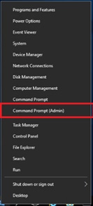
2. Open Administrative Command Prompt as admin.
3. Open notepad.
4. Layout the following parameters in the text file:
a. HORCM_MON. Defines the IP Address to listen on, UDP Port, and timeout values.
b. HORCM_CMD. Defines the local CMDs, or the Remote IP Address of a singular array.
c. HORCM_LDEV / HORCM_LDEVG / HORCM_DEV. Defines one or more lists of devices participating in replication.
d. HORCM_INST. The remote location of the list of devices.
5. Using a command prompt issue command netstat -a to find available UDP ports that can be used within the HORCM file. For in band or out of band you must use [31000 + horcminstance +x].
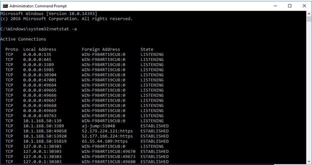
6. For your HORCM file, define HORCM_MON attribute, set your Pair Management Server IP, UDP Port, and Timeout values.
7. Using the command prompt, change to your C:\HORCM\etc directory.
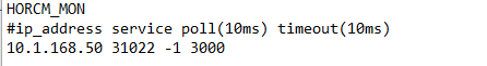
8. Run command raidscan -x findcmddev #(0-25), this will scan your system for any CMD s with drive numbers 0 to 25. In this case you can see your CMD is from our VSP 5100 system with serial 530506 linked to physical drive 1.
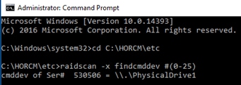
9. For HORCM_CMD, define the value from the prior command to the applicable CMD for the system you are using to create your GAD pair.

10. For HORCM_VCMD, define the virtual serial number of the VSM that is being emulated between primary VSP 5100 and secondary VSP G370.
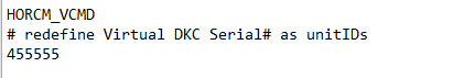
11. For HORCM_LDEV, you must define an arbitrary group and device name, along with the serial number of the VSM being emulated. You must also define your LDEV value of the GAD pair that is native to the storage system. I.E If P-Vol on VSP 5100 is FC, LDEV defined in HORCM file 0 must reflect this.

12. For HORCM_INST, you must define the group name and IP address, and UDP that is utilized by the secondary HORCM 1 file on pair management server 2. For example, if HORCM_MON of HORCM 1 has an IP address of 10.2.168.50 and a UDP listener port of 31023, HORCM_INST of HORCM 0 will call out these values.
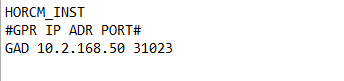
13. When completed, HORCM 0 will have the following representation:
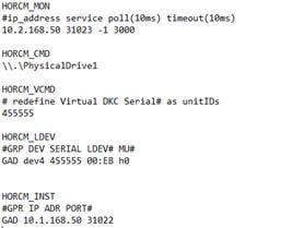
14. Repeat steps 1-12 to create HORCM 1 on Pair Management Server 2.
15. When completed HORCM file 1 should have the follow representation:
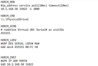
16. Start both HORCM files respectively on each Pair Management Server by issuing horcmstart.exe following by the HORCM instance. Refer to section Starting HORCM Files on Pair Management Server 1 and 2 for an example.
When both files start, you can create your pair.
Create GAD Pair using Raidcom
When you have created your HORCM files for replication you can issue a CCI command to create your GAD pair and utilize the Quorum disk presented to each respective VSP. Confirm that your replication HORCM files are running. Issue one of the following commands using CCI to create your GAD pair at Pair Management Server 1 or 2.
![]() Only one of the following commands needs to be executed on the pair management server.
Only one of the following commands needs to be executed on the pair management server.
GAD pair create operation:
paircreate -g GAD -f never -vl -jq 0 -IH0
paircreate -g GAD -f never -vl -jq 0 -IH1
When you have created the pair using CCI, you can verify pair status using the Storage Navigator.
To verify the creation of your GAD pair, follow these steps:
1. Log into Hitachi Storage Navigator for your respective VSP 5100 or VSP G370 system.
2. Expand Storage in the navigation tree.
3. Expand the Replication drop-down list.
4. Click Remote Replication.
5. Select the GAD Pairs tab.
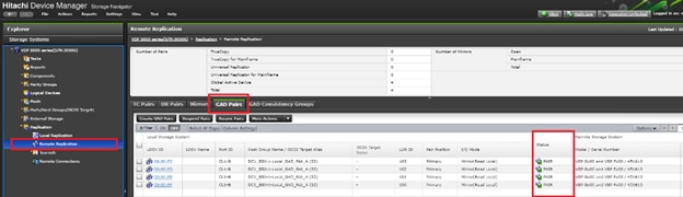
6. You can view your GAD pair status as well as issue pair operations.
![]() During the initial allocation of a GAD pair to a host, a reboot may be required.
During the initial allocation of a GAD pair to a host, a reboot may be required.
![]() In the event on a DC/GAD failure, rebooting the accessing hosts is required to access the remote GAD paths.
In the event on a DC/GAD failure, rebooting the accessing hosts is required to access the remote GAD paths.
vCenter Operations
Onboard Datastores to Hosts
When datastores have been provisioned and zoned for each of the data center, you can now onboard them to vCenter as VMFS datastores. The following steps can be utilized to onboard site-specific storage or GAD storage once provisioned to DC1 and DC2 hosts.
To add the datastores to the clusters, follow these steps:
1. From the Hosts tab of the Navigator, right-click the Cluster and select Storage -> New Datastore…
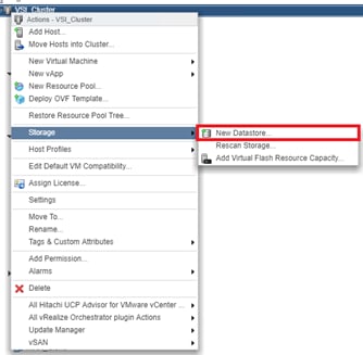
2. Click Next.
3. Leave VMFS selected and click Next.
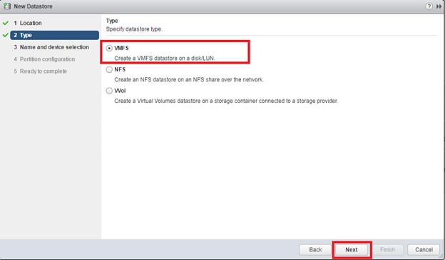
4. Provide an appropriate datastore name and select the appropriate LUN. If site-specific, use naming convention DC1-DS or DC2-DS.
5. Click Next.
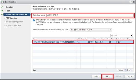
6. Leave VMFS 6 selected.
7. Click Next.
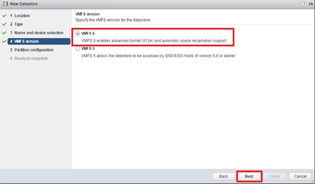
8. Leave the defaults for Partition configuration.
9. Click Next.
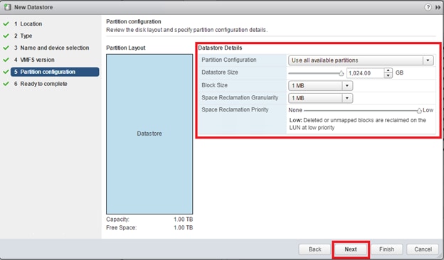
10. Review the settings.
11. Click Finish to onboard VMFS datastore.
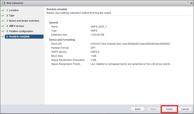
12. Check each host in the cluster associated to site specific storage to confirm access If onboarding Non-GAD storage.
13. For GAD datastores confirm all hosts have access.
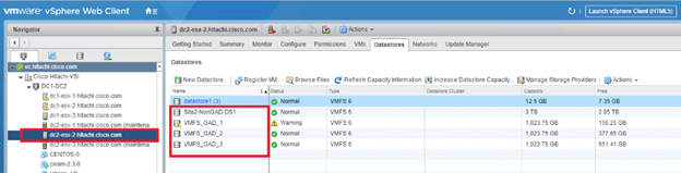
14. Repeat steps 1-12 for onboarding additional datastores.
vSphere Availability Settings
When you create a vSphere HA cluster, you must configure settings that determine how the feature works in response to:
· Failures and responses-Provide settings here for host failure responses, host isolation, VM monitoring, and VM Component Protection.
· Proactive HA failures and responses-Provide settings for how Proactive HA responds when a provider has notified its health degradation to vCenter, indicating a partial failure of that host.
· Admission Control-Enable or disable admission control for the vSphere HA cluster and choose a policy for how it is enforced.
· Heartbeat Datastores-Specify preferences for the datastores that vSphere HA uses for datastore heart beating.
With GAD storage it is highly recommended to create these responses so Virtual Machine Component Protection works as intended during a data center outage specifically related to datastore loss.
For more information on Permanent Device Loss (PDL) and All Paths Down (APD) situations among vSphere, refer to this VMware blog: https://blogs.vmware.com/vsphere/2015/06/vm-component-protection-vmcp.html
In the vSphere Web Client, follow these steps to configure vSphere HA settings:
1. Log into the vSphere vCenter Web Client.

2. Select the Cluster, and click the Configure tab.
3. From the services drop down, select vSphere Availability.
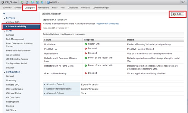
4. Click Edit…
5. Select Failures and Responses.
6. Expand on Datastore with PDL.
7. Select Power off and restart VMs.
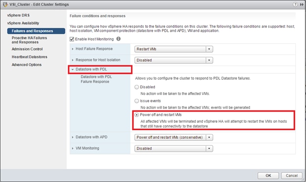
8. Expand Datastore with APD.
9. Select Power off and restart VMs – Conservative restart policy.
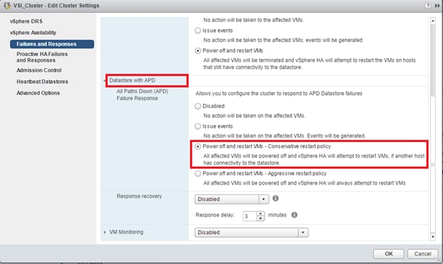
10. Click OK to confirm settings.
Create Additional VMFS Datastore(s) using Hitachi Storage Management Software for VMware vSphere (Optional)
When ESXi hosts are deployed, you can supply additional VMFS datastore(s) to the UCS environment outside of Storage Navigator using Hitachi Storage Management products directly from the VMware vCenter user interface. With Hitachi Storage Plug-in for VMWare vCenter, site specific non-GAD VMFS datastores can be allocated. Individual host groups and applicable dynamic provisioning pools via Storage Navigator must be created prior to using the Hitachi Storage Plugin for storage allocation.
![]() Boot LDEVs can only be created using Storage Navigator.
Boot LDEVs can only be created using Storage Navigator.
Deployment of Hitachi Storage Management and system onboarding is not explained in this document. Instructions to deploy and onboard can be obtained here: Hitachi Storage Plug-in for VMware vCenter
Allocate Non-GAD Datastores with Hitachi Storage Plug-in for VMware vCenter
Hitachi Storage Plug-in allows VMware administrators to supplement additional VMFS datastores in their native vSphere environments. With Hitachi Storage Plugin when creating a datastore the back end logical unit is also created native to the storage system at each data center. It is expected that DC1 and DC 2 storage systems have been registered.
To begin provisioning a VMFS Datastore using Hitachi Storage Plugin, follow these steps:
![]() Storage System(s) must be registered with the Hitachi Storage Plugin prior to datastore allocation. Refer to the Hitachi Storage Plug-in for VMware vCenter User Guide for onboarding the storage system(s).
Storage System(s) must be registered with the Hitachi Storage Plugin prior to datastore allocation. Refer to the Hitachi Storage Plug-in for VMware vCenter User Guide for onboarding the storage system(s).
![]() As of Hitachi Storage Plug-in Version 4.0, only the HTML5 client is supported.
As of Hitachi Storage Plug-in Version 4.0, only the HTML5 client is supported.
1. Log into VMware vSphere HTML5 client.
2. From the home page select the Hitachi Storage Plug-in icon.
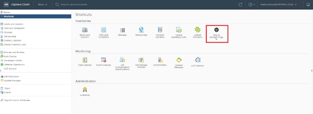
3. Select Datastores from the navigator pane.
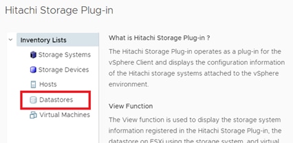
4. Click the Provision Datastore icon to begin provisioning.
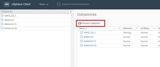
5. From the Provision Datastore wizard select provisioning type as VMFS Datastore, click Next.
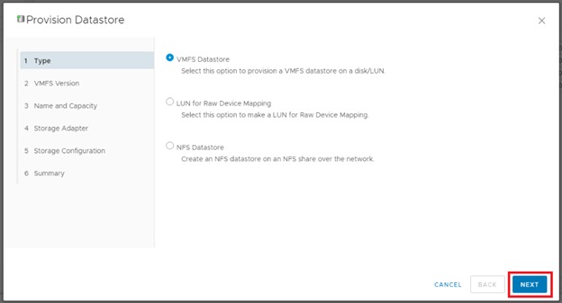
6. Select the applicable VMFS version, click Next.
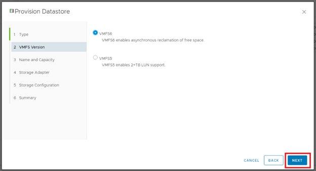
7. Choose the allocation type, define a datastore name along with capacity, click Next.
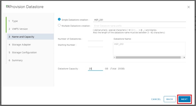
8. Click the applicable data center and select the HBAs of your hosts that are specific to your data center, click Next.
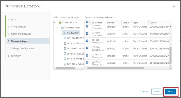
9. For the storage Configuration screen, configure the storage system for the datastore(s):
a. Select Storage System.
b. Select Storage Pool/RAID Group.
c. Specify a value for LUN ID.(Optional)
d. Select Host Group/Target.
e. Click Next
10. For the Summary screen, confirm the settings for the datastore. Click a screen name to modify any settings. Click Next.
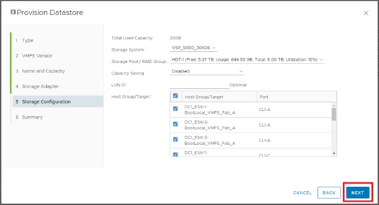
11. Click Finish. The datastore creation progress and results can be viewed in vSphere Web Client Recent Tasks.
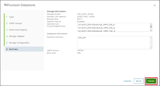
12. Repeat steps 3-11 to allocate additional VMFS datastores.
vSphere Host Pinning
VM Groups
In the event of a failure, vSphere can keep virtual machines pinned to a specific site based off backend VMFS datastore availability. Creating Host Groups and Rules will keep your Pair Management Servers which are site specific, pinned to the correct hosts during HA events.
To create VM Groups and rules, follow these steps:
1. Log into the vSphere vCenter Web Client.
2. Select the Cluster, and click the Configure tab.
3. From the services drop-down list, select VM/Host Groups.

4. Click Add.
5. Define your VM Group name as DC1-VMs and select type as VM Group.
6. Click Add.
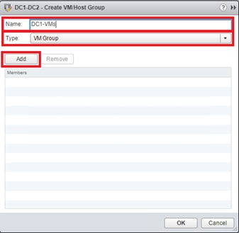
7. From the list of Virtual machines, select VSI_PMS1 as a member.
8. Click OK.
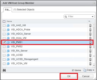
9. Click OK.
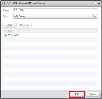
10. Repeat steps 3-9 to create DC2 VM Group and include VSI_PMS2 as its member.
11. Once complete, confirm the VM Groups are created.
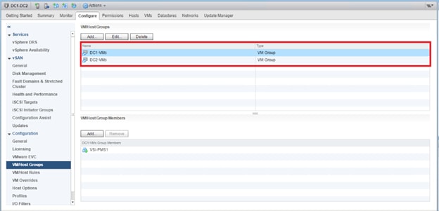
Host Groups
When you have created your virtual machine groups, you must also create host groups which define ESXi hosts logically together, this will allow us to associate the prior VM group to a ESXi host group to keep the Pair Management Servers pinned to their respective sites during an outage.
To create a VM Host Group, follow these steps:
1. Log into the vSphere vCenter Web Client.
2. Select the Cluster and click the Configure tab.
3. From the services drop-down list, select VM/Host Groups.
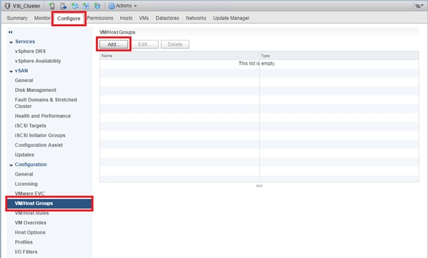
4. Click Add.
5. Define your Host Group name as DC1-Hosts and select type as Host Group.
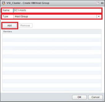
6. Click Add.
7. Select your DC1 ESXi hosts.
8. Click OK.
9. Click OK.
10. Repeat steps 3-9 to create DC2 Host Groups and include DC2 ESXi hosts as its member.
11. Once complete, confirm Host Groups are created.
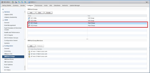
Host Rules
When you have assigned resources to VM groups as well as host groups, you can create rules to pin each VM groups to a specific host group.
To create host rules, follow these steps:
1. Log into the vSphere vCenter Web Client.

2. Select the Cluster and click the Configure tab.
3. From the services drop-down list, select VM/Host Rules.
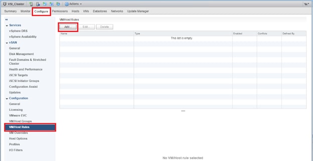
4. Click Add.
5. From the Create VM/Host Rule dialog box, define name as DC1.
6. Check the Enable rule box.
7. From type drop-down list, select Virtual Machines to Hosts.
8. From VM group drop-down list, select DC1-VMs.
9. From the next drop-down list, select Must run on hosts in group.
10. From Host Group drop-down list, select DC1-Hosts.
11. Click OK.
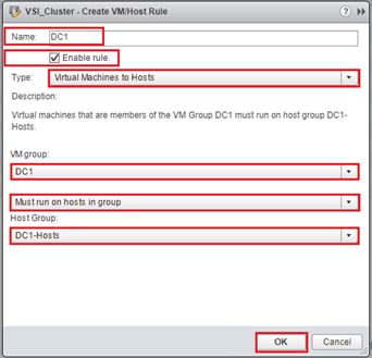
12. Repeat steps 3-11 to create DC2 host rule, make sure for VM group DC2-VMs, Must run on host in group, and DC2-Hosts are selected.
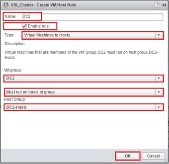
13. When complete, confirm host rules are created.
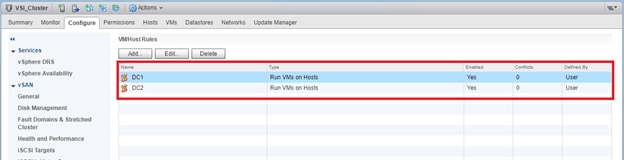
The solution was validated by deploying virtual machines running the IOMeter tool. The system was validated for resiliency by failing various aspects of the system under load. Examples of the types of tests include:
· Migrate workloads between DCs
· Complete power off of a VSP in a data center to show application continuity through GAD from the other DC
· Failure of all hosts in a DC to show VM bring up in opposing DC through HA, to include vCenter as a VM
· GAD Replication link removals
· Full DC down through loss of power, application and infrastructure continuity from the other DC, return to functionality on impacted DC after return of power
Validated Hardware
Table 41 lists the hardware and software versions used during solution validation. It is important to note that Cisco, Hitachi, and VMware have compatibility matrixes that should be referenced to determine support and are available in the Appendix, section Compatibility Matrixes.
Table 41 Validated Hardware and Software
| Component |
DC Location |
Software Version/Firmware Version |
|
| Network |
Cisco Nexus 93180YC-FX (leaf) |
Both |
14.2(1j) [14.1(2g) in initial release] |
| Cisco Nexus 9364C (spine) |
Both |
14.2(1j) [14.1(2g) in initial release] |
|
| Cisco APIC M2 |
Both |
4.2(1j) [4.1(2g) in initial release] |
|
| Cisco ExternalSwitch |
Shared |
1.1 [1.0 in initial release] |
|
| Compute |
Cisco UCS Fabric Interconnect 6454 |
Both |
4.0(4d) [4.0(4b) in initial release] |
| Cisco UCS 2208XP IOM |
Both |
4.0(4d) [4.0(4b) in initial release] |
|
| Cisco UCS B200 M5 |
Both |
4.0(4d) [4.0(4b) in initial release] |
|
| VMware vSphere |
Both |
6.7 U2 VMware_ESXi_6.7.0_13006603_Custom_Cisco_6.7.2.1.iso |
|
| ESXi 6.7 U2 nenic |
Both |
1.0.29.0 |
|
| ESXi 6.7 U2 nfnic |
Both |
4.0.0.40 [4.0.0.38 in initial release] |
|
| VMware vCenter Server Appliance |
Shared |
6.7 U2 |
|
| VM Virtual Hardware Version |
Both |
13 |
|
| Storage |
Hitachi VSP 5100 |
DC1 |
90-01-61 (SVOS 9.1.3) |
| Hitachi VSP G370 |
DC2 |
88-03-23 (SVOS 8.3.1) |
|
| Hitachi Storage Plugin for vCenter |
Shared |
4.1.0 [3.10.0 in initial release] |
|
| Hitachi Command Control Interface (CCI) |
|
01-52-03/01 |
|
| Cisco MDS 9706 |
DC1 |
8.3(2) [8.3(1) in initial release] |
|
| Cisco MDS 9148T |
DC2 |
8.3(2) |
|
| Cisco DCNM |
DC1 |
11.2(1) |
|
The Adaptive Solutions for CI with ACI is a Virtual Server Infrastructure, built as a partnership between Cisco and Hitachi to support virtual server workloads for VMware vSphere 6.7. Adaptive Solutions for CI is a best practice data center architecture that can be stretched between geographically displaced locations with the incorporated technologies of the Cisco Multi-Pod Design and Hitachi Global Active Device.
The solution is built utilizing Cisco UCS Blade Servers, Cisco Fabric Interconnects, Cisco Nexus 9000 Switches configured within Cisco ACI, Cisco MDS switches and fibre channel-attached Hitachi VSP storage. It is designed and validated using compute, network and storage best practices for high-performance, scalability, and resiliency throughout the architecture.
This Cisco Validated Design confirms the design, performance, management, scalability, and resilience that Cisco and Hitachi and provide to customers across an extended data center.
Network and Management
Cisco Nexus 9000 Series Switches:
https://www.cisco.com/c/en/us/products/switches/nexus-9000-series-switches/datasheet-listing.html
Cisco Application Centric Infrastructure:
Cisco ACI Infrastructure Best Practices Guide:
Cisco ACI Infrastructure Release 2.3 Design Guide:
Cisco ACI Multi-Pod Design:
https://www.cisco.com/c/en/us/solutions/collateral/data-center-virtualization/application-centric-infrastructure/white-paper-c11-737855.html
Cisco ACI Multi-Pod Configuration:
Cisco APIC Layer Network Configuration Guide, Release 4.0(1):
Cisco MDS 9000 Series Multilayer Switches:
Cisco Data Center Network Manager 11:
Compute
Cisco Unified Computing System:
http://www.cisco.com/en/US/products/ps10265/index.html
Cisco UCS 6400 Series Fabric Interconnects:
Cisco UCS 5100 Series Blade Server Chassis:
Cisco UCS 2200 Series Fabric Extenders:
https://www.cisco.com/c/en/us/products/collateral/servers-unified-computing/ucs-6300-series-fabric-interconnects/data_sheet_c78-675243.html
Cisco UCS B-Series Blade Servers:
http://www.cisco.com/en/US/partner/products/ps10280/index.html
Cisco UCS VIC 1440 Adapter:
Cisco UCS Manager:
http://www.cisco.com/en/US/products/ps10281/index.html
Cisco Intersight:
https://www.cisco.com/c/en/us/products/servers-unified-computing/intersight/index.html
Cisco Workload Optimization Manager:
Storage
Hitachi Global Active Device:
Hitachi Virtual Storage Platform F Series:
Hitachi Virtual Storage Platform G Series:
Virtualization Layer
VMware vCenter Server:
http://www.vmware.com/products/vcenter-server/overview.html
VMware vSphere:
https://www.vmware.com/products/vsphere
VMware vSphere Metro Storage Cluster:
https://www.vmware.com/content/dam/digitalmarketing/vmware/en/pdf/techpaper/vmware-vsphere-metro-storage-cluster-recommended-practices-white-paper.pdf
Compatibility Matrixes
Cisco UCS Hardware Compatibility Matrix:
https://ucshcltool.cloudapps.cisco.com/public/
Cisco Nexus Recommended Releases for Nexus 9K:
Cisco ACI Virtualization Compatibility Matrix:
https://www.cisco.com/c/dam/en/us/td/docs/Website/datacenter/aci/virtualization/matrix/virtmatrix.html
Cisco MDS Recommended Releases:
Cisco Nexus and MDS Interoperability Matrix:
Cisco MDS 9000 Family Pluggable Transceivers Data Sheet:
Hitachi Interoperability:
https://support.hitachivantara.com/en_us/interoperability.html sub-page -> (VSP G1X00, F1500, Gxx0, Fxx0, VSP, HUS VM VMWare Support Matrix)
VMware and Cisco Unified Computing System:
http://www.vmware.com/resources/compatibility
Ramesh Isaac, Technical Marketing Engineer, Cisco Systems, Inc.
Ramesh Isaac is a Technical Marketing Engineer in the Cisco UCS Data Center Solutions Group. Ramesh has worked in the data center and mixed-use lab settings since 1995. He started in information technology supporting UNIX environments and focused on designing and implementing multi-tenant virtualization solutions in Cisco labs before entering Technical Marketing where he has supported converged infrastructure and virtual services as part of solution offerings as Cisco. Ramesh has certifications from Cisco, VMware, and Red Hat.
Arvin Jami, Virtualization Solution Architect, Hitachi Vantara
Arvin Jami began his career at Hitachi Data Systems as an intern in 2014. Since then he has held the position of Technical Marketing Engineer where he demonstrated and positioned Hitachi products to fortune 500 companies. He is now the Virtualization Solution Architect in the Hitachi Vantara Converged Product Engineering Group. Arvin has a Bachelor of Science degree in Electrical Engineering from San Jose State University.
Acknowledgements
For their support and contribution to the design, validation, and creation of this Cisco Validated Design, the authors would like to thank:
· Haseeb Niazi, Technical Marketing Engineer, Cisco Systems, Inc.
· Archana Sharma, Technical Marketing Engineer, Cisco Systems, Inc.
· Tim Darnell, Master Solutions Architect and Product Owner, Hitachi Vantara
 Feedback