Cisco and Hitachi Adaptive Solutions for Converged Infrastructure with Cisco ACI Design Guide
Available Languages

Cisco and Hitachi Adaptive Solutions for Converged Infrastructure with Cisco ACI Design Guide
Published: September 2019
About the Cisco Validated Design Program
The Cisco Validated Design (CVD) program consists of systems and solutions designed, tested, and documented to facilitate faster, more reliable, and more predictable customer deployments. For more information, go to:
http://www.cisco.com/go/designzone.
ALL DESIGNS, SPECIFICATIONS, STATEMENTS, INFORMATION, AND RECOMMENDATIONS (COLLECTIVELY, "DESIGNS") IN THIS MANUAL ARE PRESENTED "AS IS," WITH ALL FAULTS. CISCO AND ITS SUPPLIERS DISCLAIM ALL WARRANTIES, INCLUDING, WITHOUT LIMITATION, THE WARRANTY OF MERCHANTABILITY, FITNESS FOR A PARTICULAR PURPOSE AND NONINFRINGEMENT OR ARISING FROM A COURSE OF DEALING, USAGE, OR TRADE PRACTICE. IN NO EVENT SHALL CISCO OR ITS SUPPLIERS BE LIABLE FOR ANY INDIRECT, SPECIAL, CONSEQUENTIAL, OR INCIDENTAL DAMAGES, INCLUDING, WITHOUT LIMITATION, LOST PROFITS OR LOSS OR DAMAGE TO DATA ARISING OUT OF THE USE OR INABILITY TO USE THE DESIGNS, EVEN IF CISCO OR ITS SUPPLIERS HAVE BEEN ADVISED OF THE POSSIBILITY OF SUCH DAMAGES.
THE DESIGNS ARE SUBJECT TO CHANGE WITHOUT NOTICE. USERS ARE SOLELY RESPONSIBLE FOR THEIR APPLICATION OF THE DESIGNS. THE DESIGNS DO NOT CONSTITUTE THE TECHNICAL OR OTHER PROFESSIONAL ADVICE OF CISCO, ITS SUPPLIERS OR PARTNERS. USERS SHOULD CONSULT THEIR OWN TECHNICAL ADVISORS BEFORE IMPLEMENTING THE DESIGNS. RESULTS MAY VARY DEPENDING ON FACTORS NOT TESTED BY CISCO.
CCDE, CCENT, Cisco Eos, Cisco Lumin, Cisco Nexus, Cisco StadiumVision, Cisco TelePresence, Cisco WebEx, the Cisco logo, DCE, and Welcome to the Human Network are trademarks; Changing the Way We Work, Live, Play, and Learn and Cisco Store are service marks; and Access Registrar, Aironet, AsyncOS, Bringing the Meeting To You, Catalyst, CCDA, CCDP, CCIE, CCIP, CCNA, CCNP, CCSP, CCVP, Cisco, the Cisco Certified Internetwork Expert logo, Cisco IOS, Cisco Press, Cisco Systems, Cisco Systems Capital, the Cisco Systems logo, Cisco Unified Computing System (Cisco UCS), Cisco UCS B-Series Blade Servers, Cisco UCS C-Series Rack Servers, Cisco UCS S-Series Storage Servers, Cisco UCS Manager, Cisco UCS Management Software, Cisco Unified Fabric, Cisco Application Centric Infrastructure, Cisco Nexus 9000 Series, Cisco Nexus 7000 Series. Cisco Prime Data Center Network Manager, Cisco NX-OS Software, Cisco MDS Series, Cisco Unity, Collaboration Without Limitation, EtherFast, EtherSwitch, Event Center, Fast Step, Follow Me Browsing, FormShare, GigaDrive, HomeLink, Internet Quotient, IOS, iPhone, iQuick Study, LightStream, Linksys, MediaTone, MeetingPlace, MeetingPlace Chime Sound, MGX, Networkers, Networking Academy, Network Registrar, PCNow, PIX, PowerPanels, ProConnect, ScriptShare, SenderBase, SMARTnet, Spectrum Expert, StackWise, The Fastest Way to Increase Your Internet Quotient, TransPath, WebEx, and the WebEx logo are registered trademarks of Cisco Systems, Inc. and/or its affiliates in the United States and certain other countries.
All other trademarks mentioned in this document or website are the property of their respective owners. The use of the word partner does not imply a partnership relationship between Cisco and any other company. (0809R)
© 2019 Cisco Systems, Inc. All rights reserved.
Table of Contents
Adaptive Solutions with Application Centric Infrastructure
End Point Group (EPG) Mapping within ACI
External Network Connectivity - Shared Layer 3 Out
Capacity Saving with Deduplication and Compression Options
LUN Multiplicity Per HBA and Different Pathing Options
Cisco Unified Computing System
Cisco UCS Fabric Interconnects
Cisco UCS 5108 Blade Server Chassis
Cisco UCS Virtual Interface Card
2nd generation Intel® Xeon® Scalable processors
Cisco UCS B-Series Blade Servers
Cisco UCS C-Series Rack Servers
Cisco Workload Optimization Manager within Adaptive Solutions (optional)
Cisco Application Centric Infrastructure and Nexus Switching
Cisco Nexus 9000 Series Switch
Cisco Data Center Network Manager
Hitachi Virtual Storage Platform
Hitachi Virtual Storage Platform F1500 and G1500
Hitachi Virtual Storage Platform Fx00 Models and Gx00 Models
Storage Virtualization Operating System RF
Hitachi Storage Plug-in for VMware vCenter v03.10.0
Hitachi Unified Compute Platform (UCP) Advisor v02.9.0
Hitachi Storage Provider for VMware vCenter v03.5.6
Cisco Validated Designs (CVDs) consist of systems and solutions that are designed, tested, and documented to facilitate and improve customer deployments. These designs incorporate a wide range of technologies and products into a portfolio of solutions that have been developed to address the business needs of our customers.
Cisco and Hitachi are working together to deliver a converged infrastructure solution that helps enterprise businesses meet the challenges of today and position themselves for the future. This CVD utilizes many of the same components as the initial Cisco and Hitachi Adaptive Solutions architecture but has been reimplemented to take advantage of the Cisco Application Centric Infrastructure (ACI).
Cisco ACI is a holistic architecture that introduces hardware and software innovations built upon the Cisco Nexus 9000® Series product line. Cisco ACI provides a centralized policy-driven application deployment architecture that is managed through the Cisco Application Policy Infrastructure Controller (APIC). Cisco ACI delivers software flexibility with the scalability of hardware performance.
This document describes the Cisco and Hitachi Adaptive Solutions for Converged Infrastructure as a Virtual Server Infrastructure (VSI) using Cisco ACI, which is a validated approach for deploying Cisco and Hitachi technologies as private cloud infrastructure. The recommended solution architecture is built on Cisco Unified Computing System (UCS) using the unified software release to support the Cisco UCS hardware platforms for Cisco UCS B-Series blade, Cisco UCS 6400 or 6300 Fabric Interconnects, Cisco Nexus 9000 Series switches, Cisco MDS 9000 Multilayer switches, and Hitachi Virtual Storage Platform (VSP).
Introduction
Modernizing your data center can be overwhelming, and it’s vital to select a trusted technology partner with proven expertise. With Cisco and Hitachi as partners, companies can build for the future by enhancing systems of record, supporting systems of innovation, and growing their business. Organizations need an agile solution, free from operational inefficiencies, to deliver continuous data availability, meet SLAs, and prioritize innovation.
The Adaptive Solutions for CI as a VSI is a best practice datacenter architecture built on the collaboration of Hitachi and Cisco to meet the needs of enterprise customers utilizing virtual server workloads. This second major release of the architecture has been re-tooled to use the Cisco Application Centric Infrastructure (ACI) as a comprehensive SDN solution. This architecture is composed of the Hitachi VSP connecting through the Cisco MDS multilayer switches to Cisco UCS, and further enabled with the Cisco Nexus family of switches which implement ACI.
This design is presented as a validated reference architecture, that covers specifics of products utilized within the Cisco validation lab, but the solution is considered relevant for equivalent supported components listed within Cisco and Hitachi published compatibility matrixes.
Audience
The audience for this document includes, but is not limited to; sales engineers, field consultants, professional services, IT managers, partner engineers, and customers who want to modernize their infrastructure to meet SLAs and their business needs at any scale.
Purpose of this Document
A Cisco Validated Design consists of systems and solutions that are designed, tested, and documented to facilitate and improve customer deployments. These designs incorporate a wide range of technologies and products into a portfolio of solutions that have been developed to address the business needs of our customers.
The purpose of this document is to describe Adaptive Solutions for CI as a VSI using Cisco ACI. This CI is implemented with VMware vSphere utilizing Cisco Unified Computing and Hitachi VSP, along with Cisco Nexus and MDS switches as a validated approach for deploying Cisco and Hitachi technologies as an integrated compute stack.
What’s New in this Release?
The following design uses many of the concepts and best practices of the initial release, but in this release the primary differentiators are:
· Support for Cisco ACI 4.1
· Support for the Intel Cascade Lake Processors within B200 M5 servers
· Support for Hitachi UCP Advisor
Solution Summary
Adaptive Solutions for CI with ACI is a powerful and scalable architecture, leveraging the strengths of both Cisco and Hitachi, built within an SDN framework. The Adaptive Solutions for CI datacenter implementation uses the following components:
· Cisco UCS Compute
· Cisco Nexus Switches with ACI
· Cisco MDS Multilayer Fabric Switches
· Hitachi Virtual Storage Platform
These products have been brought together as a validated reference architecture. The components are configured using the configuration and connectivity best practices from both companies to implement a reliable and scalable VSI, validated for vSphere 6.7 U2. The specific products listed in this design guide and the accompanying deployment guide have gone through a battery of validation tests confirming functionality and resilience for the components as listed. Adjustments to the architecture are supported, provided they comply with the respective compatibility lists of both companies, and relevant product specific requirements of those changes are followed.
The documented example of the implementation of this design is here: Deployment Guide for Cisco and Hitachi Converged Infrastructure for ACI.
The Adaptive Solutions for CI with ACI Solution Design implements a Virtual Server Infrastructure built to be powerful, scalable, and reliable, using the best practices of both Cisco and Hitachi. This section explains the architecture about how it was built, as well as the design options used within the solution.
Requirements
The Adaptive Solutions for CI with ACI datacenter is intended to provide a Virtual Server Infrastructure that addresses the primary needs of hosting virtual machines. This design assumes existing management infrastructure and routing have been pre-configured. These existing items include, but may not be limited to:
· An Out of Band management network
· A terminal server for console access
· An Active Directory/DNS Server
· Layer 3 connectivity to the Internet and any other adjacent enterprise networks
· Additional management components used for deployment
Physical Topology
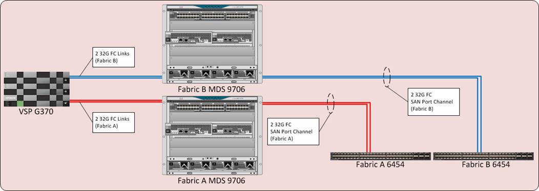
The design is validated with the Cisco UCS compute and the Hitachi VSP fibre channel traffic managed by MDS switching and the hosted virtual workload enabled with Cisco ACI managing Cisco Nexus switches. The Cisco UCS 6454 FI and the VSP G370 support 32G connectivity across the FC data path, and the Nexus leaf to spine connections within ACI can be configured for up to 100G per port. The validated topology can be seen in Figure 1.
The components of this integrated architecture shown above are:
· Cisco Nexus 93180YC-FX and Nexus 9364C leaf/spine combo – 100Gb capable, LAN connectivity to the UCS compute resources.
· Cisco Application Policy Infrastructure Controller (APIC) – Policy driven network configuration delivering application agility and network security.
· Cisco UCS 6454 Fabric Interconnect – Unified management of UCS compute, and the compute’s access to storage and networks.
· Cisco UCS B200 M5 – High powered, versatile blade server, conceived for virtual computing.
· Cisco MDS 9706 – 32Gbps Fibre Channel connectivity within the architecture, as well as interfacing to resources present in an existing data center.
· Hitachi VSP G370 – Mid-range, high performance storage system with optional all-flash configuration
Management and non-visible components of the architecture additionally include:
· Upstream L3 Gateways for accessing outside and non-ACI networks of the environment as a configured Shared L3Out.
· Cisco UCS Manager – Management delivered through the Fabric Interconnect, providing stateless compute, and policy driven implementation of the servers managed by it.
· Cisco Intersight (optional) – Comprehensive unified visibility across UCS domains, along with proactive alerts and enablement of expedited Cisco TAC communications.
· Cisco Data Center Network Manager (optional) – Multi-layer network configuration and monitoring.
· Cisco Umbrella (optional) – Secure DNS to prevent malware, phishing, and ransomware.
· Cisco Workload Optimization Manager (optional) – Resource optimization to deliver capex savings.
· Hitachi Storage Navigator – Management of Storage Virtualization Operating System (SVOS) on the VSP storage platform.
· Hitachi UCP Advisor (optional) – Comprehensive visibility and provisioning of VSP storage through vCenter.
The validation lab covered the above topology, as well as management components listed within a vSphere 6.7 U2 based hypervisor environment. Some optional components were not fully covered for use or implementation in the deployment guide, but all were in place during the validation. vSphere 6.5 was not validated but is supported within the Cisco-Hitachi Interoperability partnership.
Connectivity
Connectivity to the respective Network, Compute, and Storage elements are briefly described below.
Network Connectivity
The network connection to each of the fabric interconnects is implemented as vPC from the ACI managed upstream Nexus switches. In the switching environment, the vPC provides the following benefits:
· Allows a single device to use a Port Channel across two upstream devices
· Eliminates Spanning Tree Protocol blocked ports and use all available uplink bandwidth
· Provides a loop-free topology
· Provides fast convergence if either one of the physical links or a device fails
· Helps ensure high availability of the network
The upstream network switches which connect to the Cisco UCS 6454 Fabric Interconnects can utilize 10/25/40/100G port speeds. In this design, the FIs are connected using 25G ports into the ACI leaves that come down to the respective FIs as vPCs to present the connections as a common switch. 40G or 100G can be used depending on the application workload but will need to be reflect common bandwidth availability going between the leaves as spines that are shared with other Cisco UCS FIs or directly connected hosts that may be associated with the leaves.
From the leaves, 100G connections are used up to the ACI spines that are concurrently active within the fabric.
The APIC Cluster located on the right side of Figure 2 will connect to one of the ACI leaf pairs within the ACI fabric, in this design they were not connected to the leaf pairs used for the base infrastructure. The APIC Cluster does not participate in any of the data path, so their displacement from the Adaptive Solutions infrastructure does not create any performance impact.
The connectivity to the upstream L3 gateways are not pictured but connect through an adjacent leaf pair using 10G links. More on the L3 gateways and the Shared L3Out policies they support will be covered in the ACI design section.
Compute Connectivity
The compute chassis in the design is connected to the managing fabric interconnect with at least two ports per IOM. Ethernet traffic from the upstream network and Fibre Channel frames coming from the VSP are converged within the fabric interconnect to be both Ethernet and Fibre Channel over Ethernet transmitted to the Cisco UCS servers through the IOM. These IOM connections from the Cisco UCS Fabric Interconnects to the IOMs are automatically configured as port channels with the specification of a Chassis/FEX Discovery Policy within UCSM.
These connections from the Cisco UCS 6454 Fabric Interconnect to the 2208XP IOM hosted within the chassis are shown in Figure 3.
The 2208XP IOM are shown with 4x10Gbps ports to deliver an aggregate of 80Gbps to the chassis, full population of the 2208XP IOM can support 8x10Gbps ports, allowing for an aggregate of up to 160Gbps to the chassis.
Storage Connectivity
The VSP platform connects through the Cisco MDS 9706 to the fabric interconnects. For the fabric interconnects, these are configured as SAN Port Channels, with N_Port ID Virtualization (NPIV) enabled on the MDS. This configuration allows:
· Increased aggregate bandwidth between the fabric interconnects and the MDS
· Load balancing between the links
· High availability in the event of a failure of one or more of the links
Figure 4 illustrates the connectivity of the VSP G370 storage system to the Cisco UCS 6454 Fabric Interconnects.
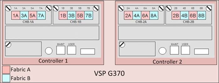
Hitachi VSP FC Port to Fabric Assignments
Each VSP storage system is comprised of multiple controllers and fibre channel adapters that control connectivity to the fibre channel fabrics. Channel board adapters (CHAs) are used within the VSP F1500 and G1500, and channel boards (CHBs) are used within the VSP Fx00 models and Gx00 models. The multiple CHA/CHBs within each storage system allow for designing multiple layers of redundancy within the storage architecture, increasing availability and maintaining performance during a failure event. The VSP F350, F370, F700, F900, F1500, G350, G370, G700, G900, and G1500 CHA/CHBs each contain up to four individual fibre channel ports, allowing for redundant connections to each fabric in the Cisco UCS infrastructure.
Hitachi VSP Fx00 models and Gx00 models have two controllers contained within the storage system. The port to fabric assignments for the VSP G370 used in this design are shown in Figure 5, illustrating multiple connections to each fabric and split evenly between VSP controllers and 32Gb CHBs:
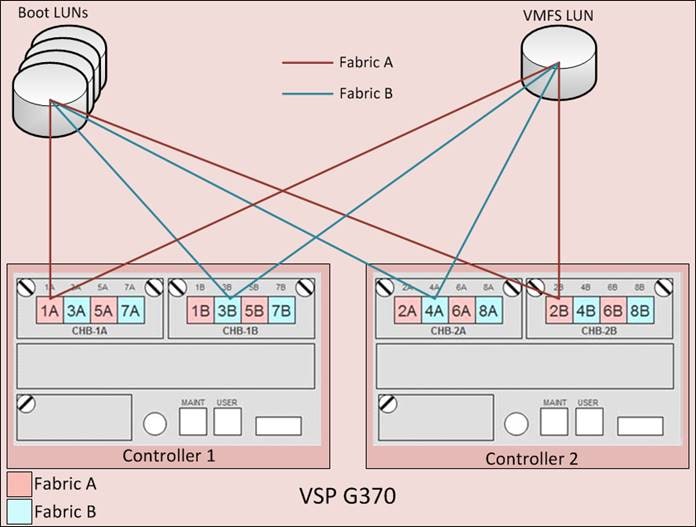
Hitachi VSP LUN Presentation and Path Assignments
Due to Cisco UCS’s ability to provide alternate paths for the boot LUN on each fibre channel fabric, four paths to each boot LUN were assigned, comprised of two paths on each fabric. For LUNs used as VMFS volumes, redundant paths for each LUN considering controller and cluster failure were assigned, comprised of two to four paths per fabric depending on the VSP model used. Figure 6 illustrates the boot LUN and VMFS LUN pathing configuration for the VSP G370.
MDS Zoning
Zoning within the MDS is configured for each host with single initiator multiple target zones, leveraging the Smart Zoning feature of the MDS for greater efficiency. The design implements a simple, single VSAN layout per fabric within the MDS, but configuration of differing VSANs for greater security and tenancy are supported.
Initiators (UCS hosts) and targets (VSP controller ports) are set up with device aliases within the MDS for easier identification within zoning and flogi connectivity. Configuration of zoning and the zonesets containing them can be managed via CLI but is also available for creation and editing with DCNM for a simpler administrative experience.
More information about zoning and the Smart Zoning feature is described in the Storage Design section.
End-to-End FC Data Path
The storage architecture in this design is built around the implementation of fibre channel storage sitting adjacent to the ACI fabric, being carried through the Cisco MDS. This is a high bandwidth solution making possible 32G end to end FC for the Cisco UCS 6454 to the VSP G370 as shown in Figure 7.
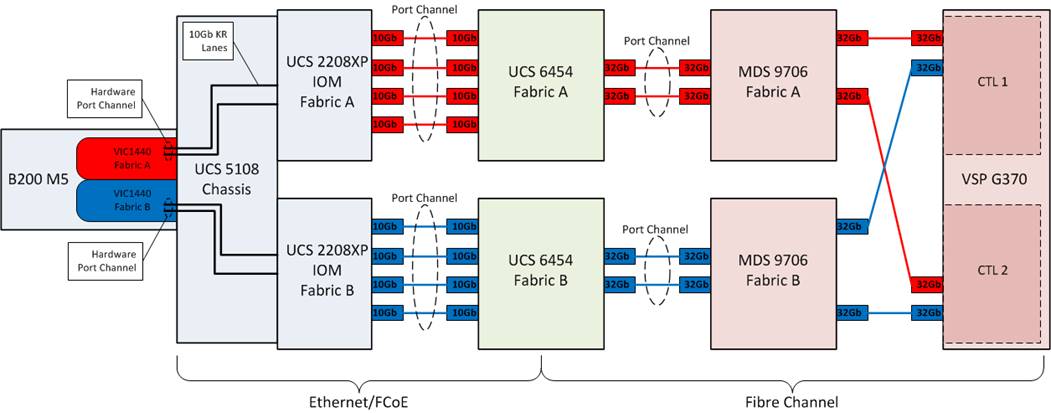
· The Cisco UCS B200 M5 blade server, equipped with a Cisco UCS VIC 1440 adapter(1), connects to each fabric at a link speed of 20Gbps.
· Pathing through 10Gb KR lanes of the Cisco UCS 5108 Chassis backplane into the Cisco UCS 2208XP IOM (Fabric Extender).
· Connecting from each IOM to the Fabric Interconnect with pairs of 10Gb uplinks automatically configured as port channels during chassis association, that carry the FC frames as FCoE along with the Ethernet traffic coming from the chassis blades.
· Continuing from the Cisco UCS 6454 Fabric Interconnects into the Cisco MDS 9706 with multiple 32G FC ports configured as a port channel for increased aggregate bandwidth and link loss resiliency.
· Ending at the Hitachi VSP G370 fibre channel controller ports with dedicated F_Ports on the Cisco MDS 9706 for each N_Port WWPN of the VSP controller, with each fabric evenly split between the controllers and CHBs.
(1) The VIC 1440 will work with the Cisco UCS 6454 to provide 40G/40G when equipped with the 4th generation IOM which is not available at the time of this validation.
Network Design
Adaptive Solutions with Application Centric Infrastructure
This Cisco and Hitachi ACI design consists of Cisco Nexus 9500 and 9300 based spine/leaf switching architecture controlled using a cluster of three Application Policy Infrastructure Controllers (APICs). With the Nexus switches in place, the platform delivers an intelligently designed, high port density, low latency network, supporting up to 100G connectivity.
Cisco ACI delivers a resilient fabric to satisfy today's dynamic applications. ACI leverages a network fabric that employs industry proven protocols coupled with innovative technologies to create a flexible, scalable, and highly available architecture of low-latency, high-bandwidth links. This fabric delivers application instantiations using profiles that house the requisite characteristics to enable end-to-end connectivity.
The ACI fabric is designed to support the industry trends of management automation, programmatic policies, and dynamic workload provisioning. The ACI fabric accomplishes this with a combination of hardware, policy-based control systems, and closely coupled software to provide advantages not possible in other architectures.
Cisco ACI Fabric
The Cisco ACI fabric consists of three major components:
· The Application Policy Infrastructure Controller (APIC) - The Cisco APIC is the unifying point of automation and management for the Cisco ACI fabric. The Cisco APIC provides centralized access to all fabric information, optimizes the application lifecycle for scale and performance, and supports flexible application provisioning across physical and virtual resources. The Cisco APIC exposes northbound APIs through XML and JSON and provides both a command-line interface (CLI) and GUI which utilize the APIs to manage the fabric.
· Spine switches - The ACI spine switch provides the mapping database function and the connectivity among leaf switches. A spine switch can be the modular Cisco Nexus 9500 series equipped with ACI ready line cards or fixed form-factor switch such as the Cisco Nexus 9364C (used in this design). Spine switches provide high-density 40/100 Gigabit Ethernet connectivity between the leaf switches.
· Leaf switches - The ACI leaf provides physical connectivity for servers, storage devices and other network elements as well as enforces ACI policies. A leaf typically is a fixed form factor switch such as the Cisco Nexus 93180YC-FX switch used in the current design. Leaf switches also provide the connection point to the existing enterprise or service provider infrastructure. The leaf switches provide options starting at 1G up through 100G Ethernet ports for connectivity.
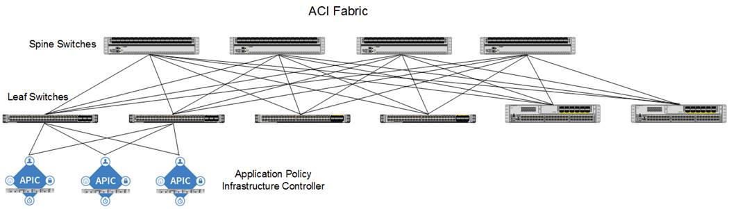
The ACI switching architecture, illustrated in Figure 8, is presented in a leaf-and-spine topology where every leaf connects to every spine using 40/100G Ethernet interface(s).
Cisco ACI Tenant Model
The ACI Tenant sits within the ACI Fabric to deliver policy-based connectivity to physical and virtual devices defined as End Point Groups. The primary components for delivering the tenant model are:
· Tenant: A tenant is a logical container which can represent an actual tenant, organization, application or a construct to easily organize information. From a policy perspective, a tenant represents a unit of isolation. All application configurations in Cisco ACI are part of a tenant. Within a tenant, one or more VRF contexts, one or more bridge domains, and one or more EPGs can be defined according to application requirements.
The Adaptive Solutions with ACI design implements an infrastructure tenant called "CHV-Foundation" to provide access to the management infrastructure including vSphere and AD/DNS. The design also utilizes the predefined "common" tenant to provide access to a Shared L3-Out for use to access non-ACI networks that may be in the environment as well as the Internet. In addition, each subsequent application deployment requires creation of a dedicated tenant.
![]() CHV is used in this document as an identifying prefix within the ACI fabric for the Cisco and Hitachi Virtual Server Infrastructure configuration. This prefix is optional, but also provides some insight into the tenancy potential while implementing ACI.
CHV is used in this document as an identifying prefix within the ACI fabric for the Cisco and Hitachi Virtual Server Infrastructure configuration. This prefix is optional, but also provides some insight into the tenancy potential while implementing ACI.
· VRF: Tenants can be further divided into Virtual Routing and Forwarding (VRF) instances (separate IP spaces) to further separate the organizational and forwarding requirements for a given tenant. Because VRFs use separate forwarding instances, IP addressing can be duplicated across VRFs for multitenancy. In the current design, each tenant is typically supported by its own VRF, along with shared access to a dedicated VRF in the common tenant for L3-Out.
· Application Profile: An application profile models application requirements and contains one or more End Point Groups (EPGs) as necessary to provide the application capabilities. Depending on the application and connectivity requirements, the ACI design uses multiple application profiles to define multi-tier applications as well as to establish storage connectivity.
· Bridge Domain: A bridge domain represents an L2 forwarding construct within the fabric. One or more EPGs can be associated with one bridge domain or subnet. In ACI, a bridge domain represents the broadcast domain and the bridge domain might not allow flooding and ARP broadcast depending on the configuration. The bridge domain has a global scope, while VLANs do not. Each endpoint group (EPG) is mapped to a bridge domain. In ACI, a bridge domain can have one or more subnets associated with it and one or more bridge domains together form a tenant network.
· End Point Group: An End Point Group (EPG) is a collection of physical and/or virtual end points that require common services and policies. An EPG example is a set of servers or VMs on a common VLAN segment providing a common function or service. While the scope of an EPG definition is much wider, in the simplest terms an EPG can be defined on a per VLAN basis where all the servers or VMs on a common LAN segment become part of the same EPG.
In the ACI design, various application tiers, ESXi VMkernel ports for Management and vMotion are mapped to various EPGs. The design details are covered in the following sections.
· Contracts: Contracts define inbound and outbound traffic filter, QoS rules and Layer 4 to Layer 7 redirect policies. Contracts define the way an EPG can communicate with another EPG(s) depending on the application requirements. Contracts are defined using provider-consumer relationships; one EPG provides a contract and another EPG(s) consumes that contract. Contracts utilize filters to limit the traffic between the applications to certain ports and protocols. Contracts created from the common tenant can be consumed by and tenant, inter-tenant contracts not originating from the common tenant will need to be exported from the providing tenant before becoming available.
Figure 9 illustrates the relationship between various ACI Tenant elements as deployed in the validated architecture by highlighting the Foundation tenant. As shown in the figure, a Tenant can contain one or more application profiles and an application profile can contain one or more EPGs. Devices in the same EPG can talk to each other without any special configuration. Devices in different EPGs can talk to each other using contracts and associated filters. A tenant can also contain one or more VRFs and bridge domains. Different application profiles and EPGs can utilize the same VRF or the bridge domain. The subnet can be defined within the EPG but is preferably defined at the bridge domain by convention.
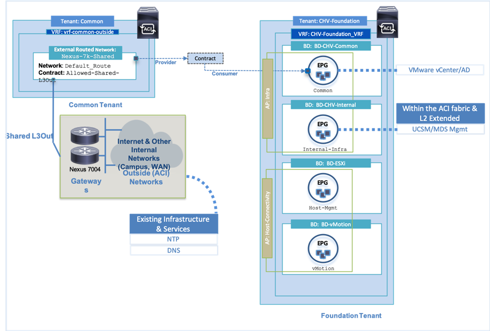
Specific to the Foundation Tenant shown in Figure 9, there are two Application Profiles which are acting as logical groupings of the EPGs within the Foundation Tenant. In the Foundation Tenant, the bridge domain to EPG was in a 1:1 ratio with the subnet used by each EPG specified within the bridge domain.
Within the validated architecture, there was also an Application Tenant configured that provides a slightly different view of options as shown in Figure 10. The same relationships occur between the differing tenant elements, but the Application Tenant was provisioned with all EPGs in the same Application Profile and all EPGs in the same Bridge Domain. In this type of configuration, the subnet was set within the bridge domain, but the member EPGs holding endpoints in the same subnet do not have connectivity amongst each other without a contract in place.
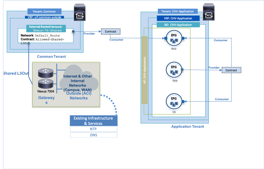
The connectivity for the Application EPGs shown within the tenant breaks down to both Web and DB having connectivity to App, but not each other, and only Web having connectivity to outside networks.
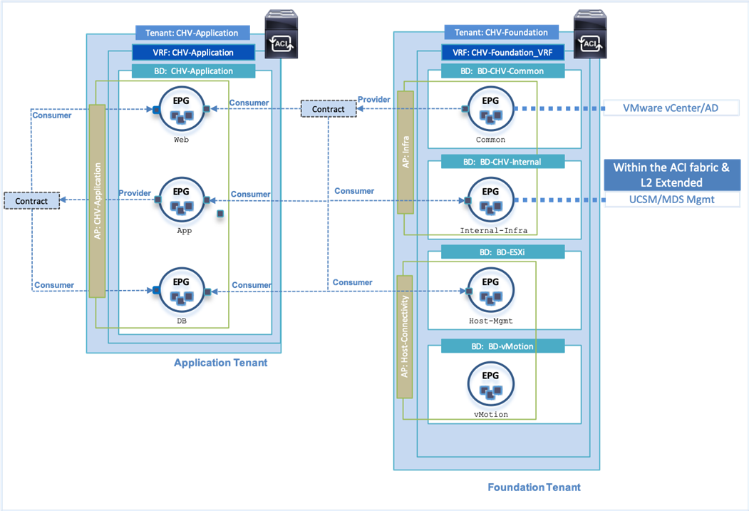
Some additional Inter-tenant and Intra-tenant contract relationships can be seen in Figure 11 for the provided contract from the Foundation tenant’s Common tenant holding the AD and vCenter servers. These resources are needed by other EPGs within Foundation for both vCenter and AD and is additionally exported to the Application tenant so each Application tenant EPG can consume the contract to reach the AD server.
End Point Group (EPG) Mapping within ACI
In ACI, traffic is associated with an EPG in one of the following ways:
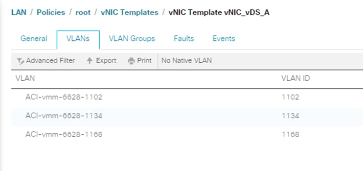
· Statically mapping a Path/VLAN to an EPG (Figure 12).
· Associating an EPG with a Virtual Machine Manager (VMM) domain thereby allocating a VLAN dynamically from a pre-defined pool in APIC (Figure 13).
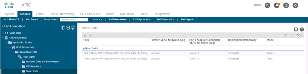
Statically mapping of Path/VLAN to an EPG is useful for:
· Mapping bare metal servers to an EPG.
· Mapping vMotion VLANs on the Cisco UCS/ESXi Hosts to an EPG.
· IP based storage connections for a storage controller.
· Mapping the management connections for infrastructure like the UCS FI and MDS, or existing infrastructure that might be connecting to a non-ACI switch.
Dynamically mapping a VLAN to an EPG by defining a VMM domain is useful for:
· Deploying VMs in a multi-tier Application requiring one or more EPGs.
· Potentially deploying application specific IP based storage access within the application tenant environment.
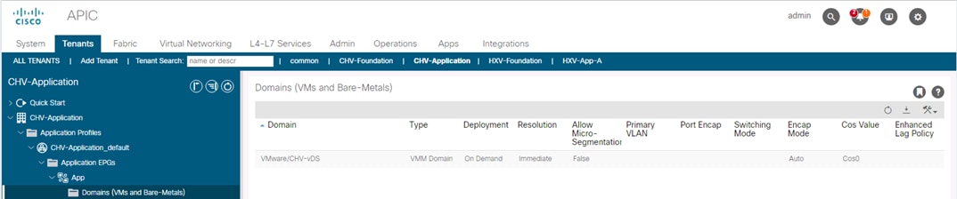
Virtual Machine Manager (VMM) Domains
In a VMware vCenter environment, Cisco APIC controls the creation and configuration of the VMware vSphere Distributed Switch (vDS) or the Cisco Application Virtual Edge (AVE, which is not covered in this document). Once the virtual distributed switches are deployed, APIC communicates with the switches to publish network policies that are applied to the virtual workloads including creation of port groups for VM association. A VMM domain can contain multiple EPGs and hence multiple port groups. To position an application, the application administrator deploys the VMs using VMware vCenter and places the vmnic into the port group defined for the appropriate application tier.
Cisco UCS Integration with ACI
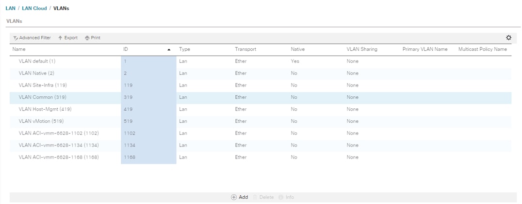
New to ACI 4.1 is an integration with Cisco UCS Manager (UCSM) to allow VMM synchronization of VLANs dynamically allocated to the EPGs to be configured within UCSM using an ACI app named ExternalSwitch.
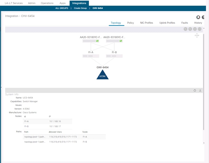
With ExernalSwitch installed, and integration manager connection can be created allowing the allocated VLANs to be configured within Cisco UCS.
As well as automatic insertion into the designated vNIC templates.
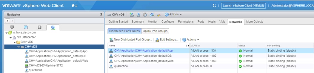
Port Group creation for VMware vDS
When application EPGs are attached to a VMware vDS based VMM domain, Cisco APIC assigns VLANs from a pre-defined pool and uses its connection to the VMware vCenter to create a new port groups on the VMware vDS. These port groups are used to deploy application VMs in the appropriate application tier. The port group name is determined using following format: “Tenant_Name | Application Profile_Name | EPG_Name” as seen below:
ACI Plug-in for vCenter
The ACI Plugin for vCenter allows a subset of the commands available through the APIC GUI to be invoked directly from the vCenter vSphere Web Client.
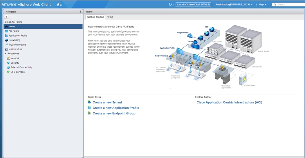
This subset of command from the APIC GUI includes Tenant creation and components, including:
· Application Profiles
· VRFs
· Bridge Domains
· EPGs
· Contracts
Giving the vSphere administrator basic abilities for managing and creating the tenant construct as it interfaces with the upstream ACI network.
External Network Connectivity - Shared Layer 3 Out
In ACI, the Layer 3 outside connection can be a shared service where it is shared by multiple tenants or it can be dedicated on a per-tenant basis. In this design, the Layer 3 outside connection is envisioned as a shared or common service that all tenants can use. In ACI, the shared Layer 3 connection that all tenants can use is referred to as a shared L3Out, and it is typically part of the common Tenant. The common tenant is a pre-defined system tenant where any objects defined in this tenant are visible to all other tenants, making it easier to position common services in which many tenants will need access.
Shared Layer 3 connections can also be defined in other tenants. However, if the goal is for all tenants to have access to this connection (if needed), then the common Tenant in the ACI architecture is defined and provided for exactly this purpose. The common Tenant provides a contract for accessing the shared L3Out connection that other tenants can consume to gain access to outside networks.
Shared L3Out Design
To enable a shared L3Out connection, border leaf nodes in the ACI fabric are connected to Layer 3 gateways in the outside network. To connect the data center to outside networks using a shared L3Out, a pair of Nexus 9000 series leaf switches are deployed as ACI border leaf switches and connected to a pair of Nexus 7000 series gateway routers in the non-ACI infrastructure. The detailed shared L3Out connectivity are shown in Figure 14, along with the ACI configuration to enable IP connectivity and routing.
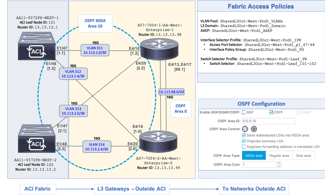
Each border leaf switch is redundantly connected to the Nexus 7000 switches using 10GbE links. The four links between ACI leaf nodes and external routers are individual connections with a dedicated VLAN and IP subnet for each link – no link bundling is used. The border leaf switches in this design also provide connectivity to the APIC nodes in the cluster. For larger deployments, Cisco recommends using a dedicated pair of border leaf switches.
A routing protocol is then enabled across the layer 3 connection to exchange routes between the ACI and non-ACI domains. OSPF is used in this design. In this design, OSPF learns routes to outside networks, and advertises ACI routes to outside networks. Routes learned by ACI in the common Tenant are then shared with other ACI Tenants by providing and consuming contracts between these Tenants. In this design, a default route is learned from the Layer 3 gateways and advertises tenant subnets to the outside infrastructure. Note that this requires ACI tenant routes to be leaked to the common Tenant and then advertised outside the fabric. The leaked routes for each Tenant must be unique – overlapping subnets should not be leaked. OSPF metrics on Cisco Nexus 7000 switches can be optionally used to influence path preferences.
The ACI constructs and design for enabling and accessing a shared L3Out service is shown in Figure 15. These include:
· A single External Routed Network under tenant common to connect ACI fabric to Cisco Nexus 7000s using OSPF.
· A unique private VRF (common-SharedL3Out_VRF) network is defined under the common tenant, which is setup with OSPF to provide connectivity to external infrastructure.
· The shared L3Out created in the common Tenant provides an external connectivity contract (Allow-Shared-L3Out) that can be consumed from any tenant. Contracts created in common Tenant are visible to all tenants. Therefore, the contract to the shared L3Out is also accessible by all tenants.
· When other tenants consume the contract, the Tenant subnets shared by the tenants will get advertised to the outside infrastructure. These tenants will also learn the routes to outside networks, to access the external infrastructure networks and endpoints. The outside routes in this design is a single default route.
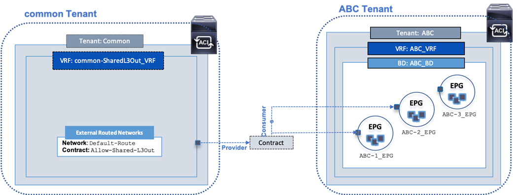
![]() By defining a shared L3Out in common tenant, the contract is provisioned as part of the L3Out configuration and it would automatically be available in all other tenants to consume, without doing any additional configuration since the objects (contracts in this example) from the common tenant are available in all other tenants. If the shared L3Out was deployed in any other tenant, the contract would have to be explicitly exported from that tenant to each tenant where this contract needs to be consumed.
By defining a shared L3Out in common tenant, the contract is provisioned as part of the L3Out configuration and it would automatically be available in all other tenants to consume, without doing any additional configuration since the objects (contracts in this example) from the common tenant are available in all other tenants. If the shared L3Out was deployed in any other tenant, the contract would have to be explicitly exported from that tenant to each tenant where this contract needs to be consumed.
Compute Design
Cisco UCS
This section explains the design decisions used within the Cisco UCS compute layer for both resiliency and ease of implementation.
Cisco UCS B-Series
The Cisco UCS B-Series servers were selected for this converged infrastructure. Supporting up to 3TB of memory in a half width blade format, these Cisco UCS servers are ideal virtualization hosts. These servers are configured in the design with:
· Diskless SAN boot – Persistent operating system installation, independent of the physical blade for true stateless computing.
· VIC 1440 – Dual-port 40Gbps capable of up to 256 Express (PCIe) virtual adapters
· Second-generation Intel Xeon Scalable processors
Cisco UCS Service Profiles and Cisco UCS Service Profile Templates
Cisco UCS Service Profiles (SP) were configured with identity information pulled from pools (WWPN, MAC, UUID, and so on) as well as policies covering firmware to power control options. These SP are provisioned from Cisco UCS Service Profile Templates that allow rapid creation, as well as guaranteed consistency of the hosts at the UCS hardware layer.
Cisco UCS vNIC Templates
Cisco UCS virtual Network Interface Cards (vNICs) are created as virtual adapters from the Cisco UCS VICs in the host, and vNIC Templates provide a repeatable, reusable, and adjustable sub-component of the SP template for handling these vNICs. These vNICs templates were adjusted within the options for:
· Fabric association or failover between fabrics
· VLANs that should be carried
· Native VLAN specification
· VLAN and setting consistency with another vNIC template
· vNIC MTU
· Consistent Device Naming (CDN) used to guarantee the expected order of interfaces
· Specification of a MAC Pool
Cisco UCS vMedia
The installation of ESXi is simplified at scale through the use of a Cisco UCS vMedia policy to present the installation ISO through the network. The HTTP service was used to validate this from an existing resource in the environment, but HTTPS, NFS, and CIFS are additional options for presenting the ISO.
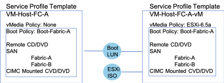
During the initial setup, the template for the ESXi hosts were created, as shown on the left. This template was cloned and adjusted to add a vMedia Policy to allow for a boot from ISO. Hosts are provisioned from this vMedia enabled template and after installation, the provisioned Service Profiles are unbound from the template enabled for vMedia and bound to the template without the vMedia Policy.
VMware vSphere
VMware vSphere is the hypervisor in this design using vSphere 6.7 U2. Design implementations discussed should be applicable for a vSphere 6.5 environment as well.
Virtual Networking Configuration
The virtual networking configuration on the Cisco UCS B200s takes advantage of the Cisco UCS VIC adapter to create multiple virtual adapters to present to the ESXi installation as shown in Figure 17.
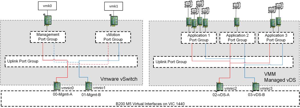
The ESXi management interfaces are carried on a single pair of vNICs delivering dedicated VLANs for In-Band management and for vMotion used by the host. These vNICs are connected to a VMware vSwitch for simplification of configuration, and to ensure portability if the vCenter was somehow compromised. The VMkernel configuration of both management and vMotion are pinned in an active/standby configuration setting on opposing links, to keep these types of traffic contained within a particular Cisco UCS fabric interconnect when switching this traffic between ESXi hosts, thus preventing the need to send it up into the Nexus switch to pass between fabrics.
All application traffic is set off of another pair of vNICs coming from the VIC adapter that are associated to the VMM managed vDS to allow of quick expansion of additional application port groups, and assurance of consistency between ESXi hosts.
Storage Design
Several design options are available with Hitachi VSP storage systems in order to service differing vSphere workloads and environments. Choose from smaller, mid-range storage which can service 600,000 IOPS and 2.4PB of capacity to enterprise-class storage which can service up to 4.8 million IOPS and 34.6PB of capacity. Table 1 lists a comparison of the different models of VSP available within the families tested in this design.
Table 1 Comparison of VSP Family Models
| VSP Model |
F350, F370, G350, G370 |
F700, G700 |
F900, G900 |
F1500, G1500 |
| Storage Class |
Mid-Range |
Enterprise |
||
| Maximum IOPS |
600K to 1.2M IOPS
9 to 12GB/s bandwidth |
1.4M IOPS
24GB/s bandwidth |
2.4M IOPS
41GB/s bandwidth |
4.8M IOPS
48GB/s bandwidth |
| Maximum Capacity |
2.8 to 4.3PB (SSD)
2.4 to 3.6PB (HDD) |
6PB (FMD)
13PB (SSD)
11.7PB (HDD) |
8.1PB (FMD)
17.3PB (SSD)
14PB (HDD) |
8.1PB (FMD)
34.6PB (SSD)
6.7PB (HDD) |
| Drive Types |
480GB, 1.9/3.8/7.6/15TB SSD
600GB, 1.2/2.4TB 10K HDD
6/10TB 7.2K HDD |
3.5/7/14TB FMD
480GB, 1.9/3.8/7.6/15TB SSD
600GB, 1.2/2.4TB 10K HDD
6/10TB 7.2K HDD |
3.5/7/14TB FMD
1.9/3.8/7.6/15TB SSD
600GB, 1.2/2.4TB 10K HDD
6/10TB 7.2K HDD |
1.75/3.5/7/14TB FMD
7/14TB FMD HDE
960GB, 1.9/3.8/7.6/15TB SSD
600GB 15K HDD
600GB, 1.2/1.8/2.4TB 10K HDD
4/6TB 7.2K HDD |
| Maximum FC Interfaces |
16x (16/32Gb FC) |
64x (16/32Gb FC) |
80x (16/32Gb FC) |
192x (8/16Gb FC) |
Capacity Saving with Deduplication and Compression Options
Hitachi Virtual Storage Platform delivers superior all-flash performance for business-critical applications. It guarantees continuous data availability with a combination of high-density flash module drives (FMD). These drives use patented flash I/O management and specialized offload engines to maximize flash utilization. The key factor affecting accommodation on a flash device is not performance, but capacity. This makes key factors the high raw capacity which the flash device has and the saving ratio which comes from deduplication and compression functionalities.
Regarding deduplication and compression, the Hitachi Virtual Storage Platform family has two main types;
· Hitachi Storage Virtualization Operation System (SVOS) provides software-based deduplication and/or compression with post processing
· FMD hardware-based compression with Inline processing
When you use FMD hardware-based compression, enabling the accelerated compression option on all parity groups of FMD drives is required. You can use either software-based or hardware-based deduplication and compression, or a combination of both. With a combination of both options, software-based deduplication and hardware-based compression are used.
LUN Multiplicity Per HBA and Different Pathing Options
This design implements Single Initiator-Multi Target (SI-MT) zoning in conjunction with single vHBAs per fabric on the Cisco UCS infrastructure. This means that each vHBA within Cisco UCS will see multiple paths on their respective fabric to each LUN. Using this design requires the use of Cisco Smart Zoning within the MDS switches.
Different pathing options including Single Initiator-Single Target (SI-ST) are supported but may reduce availability and performance especially during a component failure or upgrade scenario within the overall data path.
Balance your bandwidth and application needs, vSphere cluster utilization, and availability requirements when evaluating alternative pathing options to deploy this solution.
Data Center Network Manager
Data Center Network Manager (DCNM) was used for device alias creation through an easy-to-use GUI interface (Figure 18).
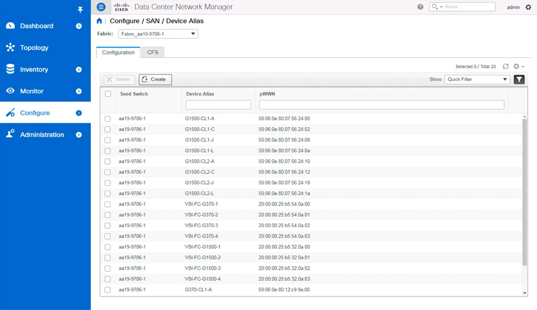
Device aliases created in this manner are valid for the seed switch specified, along with all others configured for that fabric.
The configuration of the fabric zoning and zoneset is also available within DCNM. Zones are easily created from selectable device aliases or end ports, with Smart Zoning specifiers of host, initiator, or both supported (Figure 19).
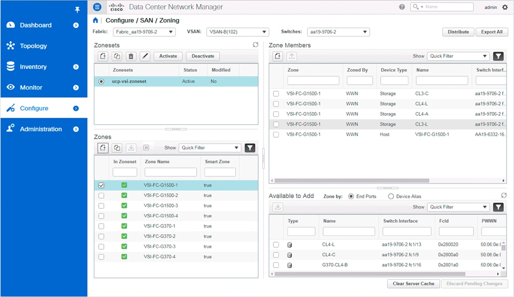
Zones created and added to a zoneset can be activated or deactivated from within DCNM for the fabric.
DCNM was used for the deployment of the validated architecture, using a pre-existing resource sitting outside of the Adaptive Solutions for CI converged infrastructure. Details of the installation of DCNM are not covered in the Deployment Guide, but pointers to the Cisco installation and configuration documents for DCNM are provided.
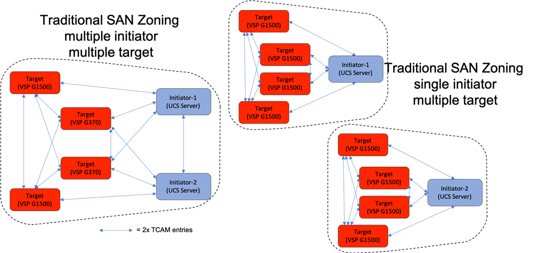
Smart Zoning
Zoning is configured as Single Initiator/Multiple Target (SI-MT) to optimize traffic intended to be specific to the initiator (UCS host vHBA) and the targets (VSP controller ports). Using SI-MT zoning provides reduced administrative overhead versus configuring single initiator/single target zoning, and results in the same SAN switching efficiency when configured with Smart Zoning.
Smart Zoning is configured on the MDS to allow for reduced TCAM (ternary content addressable memory) entries, which are fabric ACL entries of the MDS allowing traffic between targets and initiators. When calculating TCAMs used, two TCAM entries will be created for each connection of devices within the zone. Without Smart Zoning enabled for a zone, targets will have a pair of TCAMs established between each other, and all initiators will additionally have a pair of TCAMs established to other initiators in the zone as shown in Figure 20.
Using Smart Zoning, Targets and Initiators are identified, reducing TCAMs needed to only occur Target to Initiator within the zone as shown in Figure 21.
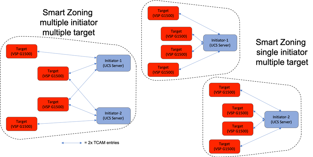
Large multiple initiator to multiple target zones can grow exponentially without smart zoning enabled. Single initiator/single target zoning will produce the same amount of TCAM entries with or without Smart Zoning but will match the TCAM entries used for any multiple target zoning method that is done with Smart Zoning.
Virtual Storage Configuration
No modifications within vSphere or at the compute layer are necessary from a base install of ESXi to take advantage of Hitachi storage hardware acceleration within vSphere. The entire line of Hitachi storage systems are certified for VMware vSphere Storage APIs Array Integration (VAAI) operations within vSphere. Certain modifications to the host groups connecting to the Cisco UCS blades running ESXi are necessary to enable full VAAI functionality for the environment and are described in the Design Considerations section.
Design Considerations
Cisco Best Practices
The following Cisco design best practices and recommendations were used as references in this design.
ACI Best Practices
The best practices for deploying a basic ACI fabric are detailed in the Cisco Application Centric Infrastructure Design Guide White Paper found here:
MDS Best Practices
The MDS design followed basic Cisco SAN concepts for the functionality of the SAN that was deployed. These concepts do not take advantage of many of the more advanced features that optimize much more complex SAN environments that the MDS 9000 and Director Class MDS 9700 series switches can offer. Some of these more advanced feature recommendations can be found here:
Cisco UCS Configuration
Cisco UCS common practices as well as a thorough background on the value of the concepts utilized within Cisco UCS are presented in this white paper:
Performance and Tuning for Cisco UCS M5 Servers
The BIOS within Cisco UCS servers present a large number of options for optimizing the servers for differing workloads. The following white paper was referenced for adjusting the BIOS selections to optimize for virtualization workloads:
Intel Xeon Scalable 2nd Generation Processor (Cascade Lake) Recommendations
The recommendations for CPU and memory configurations for differing application workloads utilizing the Intel Xeon Scalable 2nd generations processors within Cisco UCS can be found here:
Hitachi Best Practices
The following Hitachi VSP storage design best practices and recommendations were used in this design.
VMFS Provisioning Best Practices
· Fibre Channel Port Options – These settings are required to be set on each fibre channel port used in the solution.
- Port Security – Set the port security to Enable. This allows multiple host groups on the fibre channel port.
- Fabric – Set fabric to ON. This allows connection to a fibre channel switch.
- Connection Type – Set the connection type to P-to-P. This allows a point-to-point connection to a fibre channel switch.
One Host Group Per VMware ESXi Host Configuration
If you plan to deploy VMware ESXi hosts, each host’s WWN should be in its own host group. This approach provides granular control over LUN presentation to ESXi hosts. This is the best practice for SAN boot environments such as Cisco UCS, because ESXi hosts do not have access to other ESXi hosts’ boot LUNs.
· Host Group Configuration and Host Mode Options - On the Hitachi Virtual Storage Platform family storage, create host groups using Hitachi Storage Navigator. Change the following host mode and host mode options to enable VMware vSphere Storage APIs — Array Integration (VAAI):
- Host Mode – 21[VMware Extension]
- Host Mode Options:
§ Enable 54-(VAAI) Support Option for the EXTENDED COPY command
§ Enable 63-(VAAI) Support Option for vStorage APIs based on T10 standards
§ Enable 114-(VAAI) Support Option for Auto UNMAP
VMware Round Robin PSP Rotation IOPS Limit
The VMware ESXi Round Robin Path Selection Plug-in (PSP) balances the load across all active storage paths. A path is selected and used until a specific quantity of I/O has been transferred. The I/O quantity at which a path change is triggered is known as the limit. After reaching that I/O limit, the PSP selects the next path in the list. The default I/O limit is 1000 but can be adjusted if needed to improve performance. Specifically, it can be adjusted to reduce latency seen by the ESXi host when the storage system is not seeing latency. The recommended PSP limit for most environments is 1000. Based on testing in Hitachi labs, in certain circumstances setting the value to 20 can provide a potential 3-5% reduction in latency as well as a 3-5% increase in IOPS.
Auto UNMAP
· In VMware vSphere 6.5, ESXi supports manual and automatic asynchronous reclamation of free space on VMFS5 and VMFS6 datastores. It automatically issues the UNMAP command to release free storage space in background on thin-provisioned storage arrays that support UNMAP operation.
· In VMware vSphere 6.7, more granular UNMAP rates are available and are supported by Hitachi storage systems.
· Be aware that the UNMAP operations consume processor utilization on the VSP storage arrays, so test and plan ahead before increasing UNMAP rates from their default settings.
Hitachi Dynamic Tiering and Active Flash
· Using Hitachi Dynamic Tiering, you can configure a storage system with multiple storage tiers using different types of data drives. active flash monitors a page's access frequency level in real time to promote pages that suddenly became busy from a slower media to high-performance flash media.
· In a VMware environment, many workloads tend to be highly random with smaller block size. This may not be suitable for deduplication and compression, even with all flash configuration. Hitachi Dynamic Tiering with active flash may a good option to improve capacity and cost by efficiently using the flash tier minimally.
Storage DRS Recommendations
· Storage DRS generates recommendations or performs Storage vMotion migrations to balance space use across the datastore cluster. It also distributes I/O within the datastore cluster and helps alleviate high I/O load on certain datastores. VMware recommends not mixing SSD and hard disks in the same datastore cluster. However, this does not apply to the datastores provisioned from a Hitachi Dynamic Tiering pool.
The following are recommendations for VMware vSphere Storage DRS with Hitachi storage:
· Enable only Space metrics when a datastore cluster contains multiple datastores that are provisioned from the same dynamic provisioning pool with or without Hitachi Dynamic Tiering. Moving a noisy neighbor within the same dynamic provisioning pool does not improve the performance.
· Enable Space and I/O metrics when a datastore cluster contains multiple datastores that are provisioned from different dynamic provisioning pools. Moving a noisy neighbor to the other dynamic provisioning pool balances out the performance.
Storage I/O Control (SIOC) and HBA Queue Depth Recommendations
VMware vSphere Storage I/O Control (SIOC) extends the constructs of shares and limits to handle storage I/O resources. You can control the amount of storage I/O that is allocated to virtual machines during periods of I/O congestion, which ensures that more important virtual machines get preference over less important virtual machines for I/O resource allocation. In a mixed VMware environment, increasing the HBA LUN queue depth will not solve a storage I/O performance issue. It may overload the storage processors on your storage systems. The best practice from Hitachi Data Systems is to set the default HBA LUN queue depth to 32.
Compression Recommendation and Considerations
For compression, using FMD hardware-based compression is recommended for the following reasons:
· No performance degradation appears due to the truly hardware-offloaded in-line or real-time accelerated compression.
· Regarding the compression saving ratio, the differences between software-based and hardware-based are insignificant.
· Inline processing-based compression provides you with reduction of initial capacity and cost. You can estimate the required FMD capacity with the Hitachi Data Reduction Estimator. (Read more about using this tool, including how to get access to it.)
· Software-based compression consumes extra storage compute resources. This post processing-based compression requires full allocated capacity to temporarily store for the initial phase as well.
Deduplication Recommendation and Considerations
Deduplication is highly effective in the virtualization environment, which tends to have duplicated data. This includes data such as the same operating system images, templates, and backups. From lab validation results at Hitachi, enabling deduplication achieved a 60-70 percent capacity saving for a datastore where 8 virtual machines with an operating system VMDK resides (Microsoft Windows Server 2012 R2).
Enabling FMD hardware accelerated compression enhances deduplication with more than a 20 percent capacity saving. This combination of deduplication and compression achieved more than 80-90 percent capacity savings in total. You can also estimate saving ratio and deduped capacity with the Hitachi Data Reduction Estimator.
A main concern related to deduplication is performance degradation. This comes from mainly the following two factors:
· It consumes extra storage compute resources to perform deduplication and metadata management.
· The garbage collection running as a background task also require processing overhead. This task may increase storage CPU (MP) usage from 2 percent to 15 percent.
The following are some of the considerations regarding software-based deduplication:
· It may impact I/O performance. Verify the performance by utilizing best practices or the cache optimization tool (COT) tool before using the capacity saving function.
· Because approximately 10 percent of the capacity is used for metadata and garbage data, capacity saving function should be applied only when the saving is expected to be 20 percent or higher.
· In deduplication and compression, processing is performed per 8 KB. Therefore, if the block size of the file system is an integral multiple of 8 KB, then the capacity saving is likely to be effective.
· The capacity saving function is not a good fit for high-write workloads. If the write workload rate is higher than garbage collection throughput, then the storage cache write-pending increases, causing performance degradation.
· The capacity saving effect vary depends on your application and workload. You need to know your application workload and suitability before enabling a capacity saving feature.
Flash Module Drive Configurations and Recommendations
The key factor affecting accommodation on a flash device is not performance, but capacity. The required flash memory drive (FMD) capacity can vary, whether there is dedupeable or compressible data. You can estimate it by using the Hitachi Data Reduction Estimator. The following are some recommendations for FMD:
· If your application requires high IOPS and low latency, and if your data is compressible, FMD accelerated compression (without dedupe) might be an option.
· RAID-6 is the recommended RAID level for pool-VOLs, especially for a pool where recovery time from a pool failure due to a drive failure is not acceptable.
· Configure a parity group across the drive-boxes to maximize the performance by increasing the number of back-end paths.
The solution was validated by deploying virtual machines running the IOMeter tool. The system was validated for resiliency by failing various aspects of the system under load. Examples of the types of tests executed include:
· Failure and recovery of fibre channel booted ESXi hosts in a cluster
· Rebooting of fibre channel booted hosts
· Service Profile migration between blades
· Failure of partial and complete IOM links to Fabric Interconnects
· Failure and recovery of redundant links to VSP controllers from MDS switches
· Disk removal to trigger a parity group rebuild on VSP storage
· Traffic availability or loss through contract association between EPGs
Validated Hardware
Table 2 lists the hardware and software versions used during solution validation. It is important to note that Cisco, Hitachi, and VMware have compatibility matrixes that should be referenced to determine support and are available in section Appendix: Solution References.
Table 2 Validated Hardware and Software
| Component |
Software Version/Firmware Version |
|
| Network |
Cisco Nexus 93180YC-FX (leaf) |
14.1(2g) |
| Cisco Nexus 9364C (spine) |
14.1(2g) |
|
| Cisco APIC M2 |
4.1(2g) |
|
| Cisco ExternalSwitch |
1.0 |
|
| Cisco ACI Plugin |
4.1.2000.7 |
|
| Compute |
Cisco UCS Fabric Interconnect 6454 |
4.0(4b) |
| Cisco UCS 2208XP IOM |
4.0(4b) |
|
| Cisco UCS B200 M5 |
4.0(4b) |
|
| VMware vSphere |
6.7 U2 VMware_ESXi_6.7.0_13006603_Custom_Cisco_6.7.2.1.iso |
|
| ESXi 6.7 U2 nenic |
1.0.29.0 |
|
| ESXi 6.7 U2 nfnic |
4.0.0.38 |
|
| VMware vCenter Server Appliance |
6.7 U2 |
|
| VM Virtual Hardware Version |
13 |
|
| Storage |
Hitachi VSP G370 |
88-03-23 (SVOS 8.3.1) |
| Hitachi UCP Advisor |
3.0 |
|
| Hitachi Storage Plugin for vCenter |
3.10.0 |
|
| Hitachi Storage Provider for VMware vCenter (VASA) |
3.5.6 |
|
| Cisco MDS 9706 |
8.3(1) |
|
| Cisco DCNM |
11.2(1) |
|
The Adaptive Solutions for CI with ACI is a Virtual Server Infrastructure, built as a partnership between Cisco and Hitachi to support virtual server workloads for VMware vSphere 6.7. Adaptive Solutions for CI is a best practice data center architecture that can now be deployed using Cisco ACI to deliver speed and resiliency in the policy based SDN solution of the Application Centric Network.
The solution is built utilizing Cisco UCS Blade Servers, Cisco Fabric Interconnects, Cisco Nexus 9000 Switches configured within Cisco ACI, Cisco MDS switches and fibre channel-attached Hitachi VSP storage. It is designed and validated using compute, network and storage best practices for high-performance, scalability, and resiliency throughout the architecture.
This section provides a technical overview of the compute, network, storage and management components in this solution.
Cisco Unified Computing System
Cisco UCS is a next-generation data center platform that integrates computing, networking, storage access, and virtualization resources into a cohesive system designed to reduce total cost of ownership and increase business agility. The system integrates a low-latency, lossless 10-100 Gigabit Ethernet unified network fabric with enterprise-class, x86-architecture servers. The system is an integrated, scalable, multi-chassis platform with a unified management domain for managing all resources.
Cisco Unified Computing System consists of the following subsystems:
· Compute - The compute piece of the system incorporates servers based on latest Intel’s x86 processors. Servers are available in blade and rack form factor, managed by Cisco UCS Manager.
· Network - The integrated network fabric in the system provides a low-latency, lossless, 10/25/40/100 Gbps Ethernet fabric. Networks for LAN, SAN and management access are consolidated within the fabric. The unified fabric uses the innovative Single Connect technology to lowers costs by reducing the number of network adapters, switches, and cables. This in turn lowers the power and cooling needs of the system.
· Virtualization - The system unleashes the full potential of virtualization by enhancing the scalability, performance, and operational control of virtual environments. Cisco security, policy enforcement, and diagnostic features are now extended into virtual environments to support evolving business needs.
· Storage access – Cisco UCS system provides consolidated access to both SAN storage and Network Attached Storage over the unified fabric. This provides customers with storage choices and investment protection. Also, the server administrators can pre-assign storage-access policies to storage resources, for simplified storage connectivity and management leading to increased productivity.
· Management: The system uniquely integrates compute, network and storage access subsystems, enabling it to be managed as a single entity through Cisco UCS Manager software. Cisco UCS Manager increases IT staff productivity by enabling storage, network, and server administrators to collaborate on Service Profiles that define the desired physical configurations and infrastructure policies for applications. Service Profiles increase business agility by enabling IT to automate and provision resources in minutes instead of days.
Cisco UCS Differentiators
Cisco UCS has revolutionized the way servers are managed in data center and provides a number of unique differentiators that are listed below:
· Embedded Management — Servers in Cisco UCS are managed by embedded software in the Fabric Interconnects, eliminating need for any external physical or virtual devices to manage the servers.
· Unified Fabric — Cisco UCS uses a wire-once architecture, where a single Ethernet cable is used from the FI from the server chassis for LAN, SAN and management traffic. Adding compute capacity does not require additional connections. This converged I/O reduces overall capital and operational expenses.
· Auto Discovery — By simply inserting a blade server into the chassis or a rack server to the fabric interconnect, discovery of the compute resource occurs automatically without any intervention.
· Policy Based Resource Classification — Once a compute resource is discovered, it can be automatically classified to a resource pool based on policies defined which is particularly useful in cloud computing.
· Combined Rack and Blade Server Management — Cisco UCS Manager is hardware form factor agnostic and can manage both blade and rack servers under the same management domain.
· Model based Management Architecture — Cisco UCS Manager architecture and management database is model based, and data driven. An open XML API is provided to operate on the management model which enables easy and scalable integration of Cisco UCS Manager with other management systems.
· Policies, Pools, and Templates — The management approach in Cisco UCS Manager is based on defining policies, pools and templates, instead of cluttered configuration, which enables a simple, loosely coupled, data driven approach in managing compute, network and storage resources.
· Policy Resolution — In Cisco UCS Manager, a tree structure of organizational unit hierarchy can be created that mimics the real-life tenants and/or organization relationships. Various policies, pools and templates can be defined at different levels of organization hierarchy.
· Service Profiles and Stateless Computing — A service profile is a logical representation of a server, carrying its various identities and policies. This logical server can be assigned to any physical compute resource as far as it meets the resource requirements. Stateless computing enables procurement of a server within minutes, which used to take days in legacy server management systems.
· Built-in Multi-Tenancy Support — The combination of a profiles-based approach using policies, pools and templates and policy resolution with organizational hierarchy to manage compute resources makes Cisco UCS Manager inherently suitable for multi-tenant environments, in both private and public clouds.
Cisco UCS Manager
Cisco UCS Manager (UCSM) provides unified, integrated management for all software and hardware components in Cisco UCS. Using Cisco Single Connect technology, it manages, controls, and administers multiple chassis for thousands of virtual machines. Administrators use the software to manage the entire Cisco Unified Computing System as a single logical entity through an intuitive GUI, a CLI, or a through a robust API.
Cisco UCS Manager is embedded into the Cisco UCS Fabric Interconnects and provides a unified management interface that integrates server, network, and storage. Cisco UCS Manger performs auto-discovery to detect inventory, manage, and provision system components that are added or changed. It offers comprehensive set of XML API for third party integration, exposes thousands of integration points and facilitates custom development for automation, orchestration, and to achieve new levels of system visibility and control.
For more information about Cisco UCS Manager, see: https://www.cisco.com/c/en/us/products/servers-unified-computing/ucs-manager/index.html
Cisco UCS Fabric Interconnects
The Cisco UCS Fabric Interconnects (FIs) provide a single point for connectivity and management for the entire Cisco UCS system. Typically deployed as an active-active pair, the system’s fabric interconnects integrate all components into a single, highly-available management domain controlled by the Cisco UCS Manager. Cisco UCS FIs provide a single unified fabric for the system, with low-latency, lossless, cut-through switching that supports LAN, SAN and management traffic using a single set of cables.
The 4th generation (6400) Fabric Interconnect featured in this design provide a high port count, along with a limited amount of high bandwidth ports for supporting either Cisco UCS B-Series blade servers, or Cisco UCS C-Series rack-mount servers (Cisco UCS C-Series are not part of this validated design).
![]()
The Cisco UCS 6454 Fabric Interconnect is a 54 port 1/10/25/40/100GbE/FCoE switch, supporting 8/16/32Gbps FC ports and up to 3.82Tbps throughput. This model is aimed at higher port count environments that can be configured with 32Gbps FC connectivity to Cisco MDS switches or FC direct attached storage.
Table 3 lists a comparison of the port capabilities of the different Fabric Interconnect models.
Table 3 Cisco UCS 6200 and 6300 Series Fabric Interconnects
| Features |
6248 |
6296 |
6332 |
6332-16UP |
6454 |
| Max 10G ports |
48 |
96 |
96* + 2** |
72* + 16 |
48 |
| Max 25G ports |
- |
- |
- |
- |
48 |
| Max 40G ports |
- |
- |
32 |
24 |
6 |
| Max 100G ports |
- |
- |
- |
- |
6 |
| Max unified ports |
48 |
96 |
- |
16 |
8 |
| Max FC ports |
48x 2/4/8G |
96x 2/4/8G |
- |
16x 4/8/16G |
8x 8/16/32G |
* Using 40G to 4x10G breakout cables ** Requires QSA module
For more information about Cisco UCS 6454 Fabric Interconnect, see the following data sheet:
Cisco UCS 6454 - https://www.cisco.com/c/en/us/products/collateral/servers-unified-computing/datasheet-c78-741116.html
Cisco UCS Fabric Extenders
The Cisco UCS Fabric extenders (FEX) or I/O Modules (IOMs) multiplexes and forwards all traffic from servers in a blade server chassis to a pair of Cisco UCS Fabric Interconnects over a 10Gbps or 40Gbps unified fabric links. All traffic, including traffic between servers on the same chassis, or between virtual machines on the same server, is forwarded to the parent fabric interconnect where Cisco UCS Manager runs, managing the profiles and polices for the servers. FEX technology was developed by Cisco. Up to two FEXs can be deployed in a chassis.
For more information about the benefits of FEX, see: http://www.cisco.com/c/en/us/solutions/data-center-virtualization/fabric-extender-technology-fex-technology/index.html
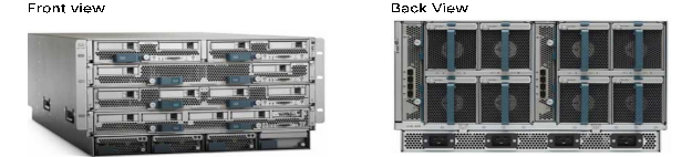
Cisco UCS 5108 Blade Server Chassis
The Cisco UCS 5108 Blade Server Chassis is a fundamental building block of the Cisco Unified Computing System, delivering a scalable and flexible blade server architecture. The Cisco UCS blade server chassis uses an innovative unified fabric with fabric-extender technology to lower TCO by reducing the number of NICs, HBAs, switches, and cables that need to be managed, cooled, and powered. It is a 6-RU chassis that can house up to 8 x half-width or 4 x full-width Cisco UCS B-Series blade servers. A passive mid-plane provides up to 80Gbps of I/O bandwidth per server slot and up to 160Gbps for two slots (full-width). The rear of the chassis contains two I/O bays to house a pair of Cisco UCS 2000 Series Fabric Extenders to enable uplink connectivity to FIs for both redundancy and bandwidth aggregation.
For more information about the Cisco UCS Blade Chassis, see: https://www.cisco.com/c/en/us/products/collateral/servers-unified-computing/ucs-5100-series-blade-server-chassis/data_sheet_c78-526830.html.
Cisco UCS Virtual Interface Card
The Cisco UCS Virtual Interface Card (VIC) converges LAN and SAN traffic with one adapter using blade or rack servers from Cisco. The Cisco UCS VIC 1400 Series extends the network fabric directly to both servers and virtual machines so that a single connectivity mechanism can be used to connect both physical and virtual servers with the same level of visibility and control. Cisco VICs provide complete programmability of the Cisco UCS I/O infrastructure, with the number and type of I/O interfaces configurable on demand with a zero-touch model. The VIC presents virtual NICs (vNICs) as well as virtual HBAs (vHBAs) from the same adapter, provisioning from 1 to 256 Express PCIe devices within UCSM.
For more information about the Cisco UCS VIC 1440 see: https://www.cisco.com/c/en/us/products/collateral/interfaces-modules/unified-computing-system-adapters/datasheet-c78-741130.html
2nd generation Intel® Xeon® Scalable processors
This release of the Adaptive Solutions for CI architecture supports the 2nd generation Intel Xeon Scalable processors in all the UCS M5 server models used in this design. These processors provide a foundation for powerful data center platforms with an evolutionary leap in agility and scalability. Disruptive by design, this innovative processor family supports new levels of platform convergence and capabilities across computing, storage, memory, network, and security resources.
Cascade Lake (CLX-SP) is the code name for the next-generation Intel Xeon Scalable processor family that is supported on the Purley platform serving as the successor to Skylake SP. These chips support up to eight-way multiprocessing, use up to 28 cores, incorporate a new AVX512 x86 extension for neural-network and deep-learning workloads, and introduce persistent memory support. Cascade Lake SP–based chips are manufactured in an enhanced 14-nanometer (14-nm++) process and use the Lewisburg chip set.
Cisco UCS B-Series Blade Servers
Cisco UCS B-Series Blade Servers are based on Intel Xeon processors. They work with virtualized and non-virtualized applications to increase performance, energy efficiency, flexibility, and administrator productivity. The latest M5 B-Series blade server models come in two form factors; the half-width Cisco UCS B200 Blade Server and the full-width Cisco UCS B480 Blade Server. These M5 server uses the latest Intel Xeon Scalable processors with up to 28 cores per processor. The Cisco UCS B200 M5 blade server supports 2 sockets, 3TB of RAM (using 24 x128GB DIMMs), 2 drives (SSD, HDD or NVMe), 2 GPUs and 80Gbps of total I/O to each server. The Cisco UCS B480 blade is a 4 socket system offering 6TB of memory, 4 drives, 4 GPUs and 160 Gb aggregate I/O bandwidth.
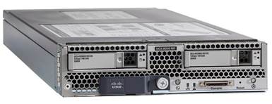
Each supports the Cisco VIC 1400 series adapters to provide connectivity to the unified fabric.
For more information about Cisco UCS B-series servers, see: https://www.cisco.com/c/en/us/products/collateral/servers-unified-computing/ucs-b-series-blade-servers/datasheet-c78-739296.html
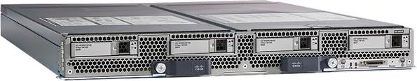
Cisco UCS C-Series Rack Servers
Cisco UCS C-Series Rack Servers deliver unified computing in an industry-standard form factor to reduce TCO and increase agility. Each server addresses varying workload challenges through a balance of processing, memory, I/O, and internal storage resources. The most recent M5 based C-Series rack mount models come in three main models; the Cisco UCS C220 1RU, the Cisco UCS C240 2RU, and the Cisco UCS C480 4RU chassis, with options within these models to allow for differing local drive types and GPUs.
For more information about Cisco UCS C-series servers, see:
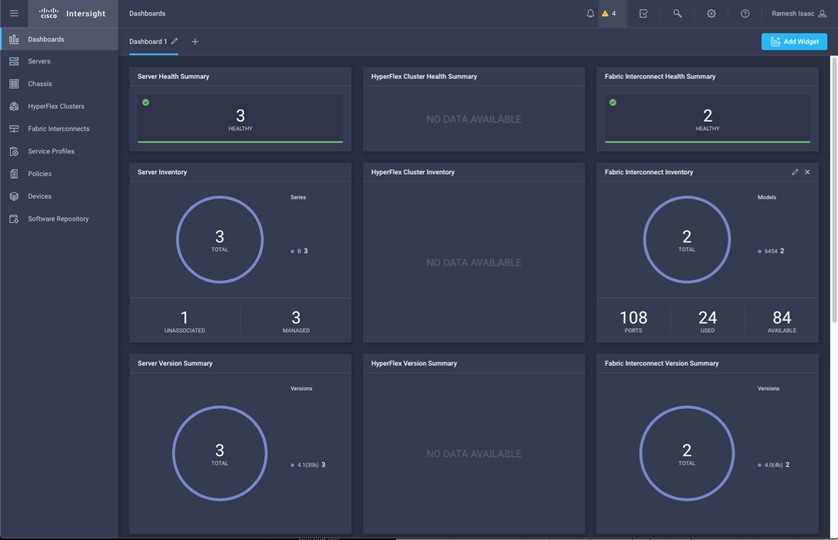
Cisco Intersight (optional)
Cisco Intersight gives IT operations management to claimed devices across differing sites, presenting these devices within a unified dashboard. The adaptive management of Intersight provides visibility and alerts to firmware management, showing compliance across managed UCS domains, as well as proactive alerts for upgrade recommendations. Integration with Cisco TAC allows the automated generation and upload of tech support files from the customer.
Each Cisco UCS server or Cisco HyperFlex system automatically includes a Cisco Intersight Base edition at no additional cost when the customer accesses the Cisco Intersight portal and claims the device. In addition, customers can purchase the Cisco Intersight Essentials edition using the Cisco ordering tool.
A view of the unified dashboard provided by Intersight can be seen in Figure 26.
For more information about Cisco Intersight, see: https://www.cisco.com/c/en/us/products/collateral/servers-unified-computing/intersight/datasheet-c78-739433.html
Cisco Umbrella (optional)
Cisco Umbrella is the delivery of secure DNS through Cisco’s acquisition of OpenDNS. Umbrella stops malware before it can get a foothold by using predictive intelligence to identify threats that next-generation firewalls might miss. Implementation is easy as pointing to Umbrella DNS servers, and unobtrusive to the user base outside of identified threat locations they may have been steered to. In addition to threat prevention, Umbrella provides detailed traffic utilization as shown in Figure 27.
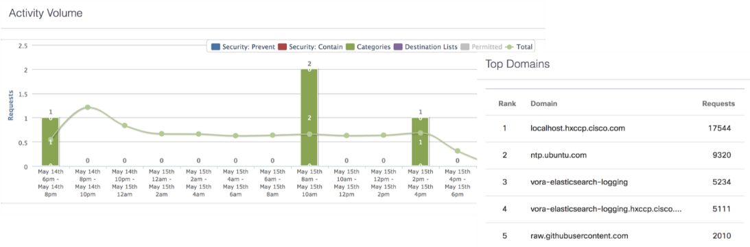
For more information about Cisco Umbrella, see: https://www.cisco.com/c/dam/en/us/products/collateral/security/router-security/opendns-product-overview.pdf
Cisco Workload Optimization Manager within Adaptive Solutions (optional)
To perform intelligent workload management, Cisco Workload Optimization Manager (CWOM) models your environment as a market of buyers and sellers linked together in a supply chain. This supply chain represents the flow of resources from the datacenter, through the physical tiers of your environment, into the virtual tier and out to the cloud. By managing relationships between these buyers and sellers, CWOM provides closed-loop management of resources, from the datacenter, through to the application.
When you launch CWOM, the Home Page gives options for:
· Planning
· Placement
· Reports
· Overall Dashboard
Giving views specific to On-Prem, the Cloud, or a Hybrid view of infrastructure, applications, and costs across both.
For basic optimization within CWOM, problems can be visible within the base dashboard:
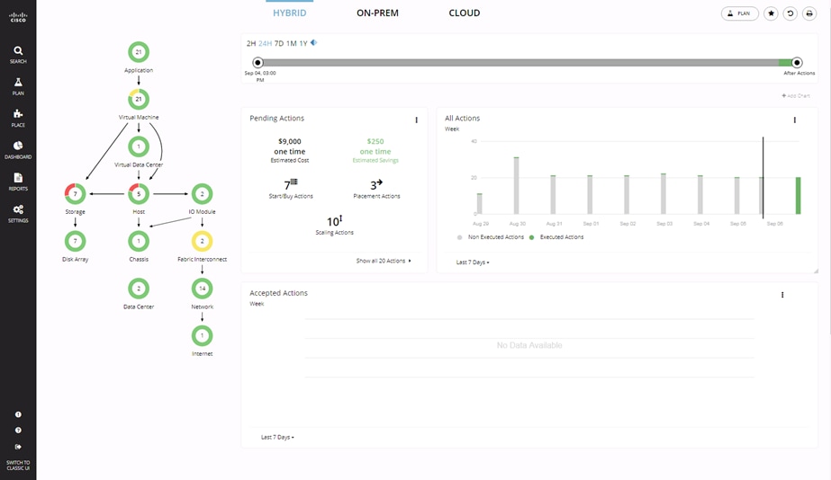
Delving into a graphical object like the Host shown above, problems and pending actions can be shown to resolve issues within the environment.
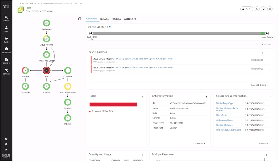
After suggested actions are performed, the hosts within the environment can be seen to be cleared of alarms.
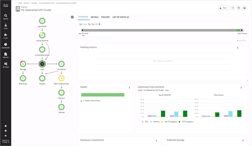
Comprehensive actions are mapped for recommendation to differing performance criteria, as well as automated remediation options are possible within policies for the defined datacenter object.
CWOM Summary
With the CWOM Platform and Cisco UCS data center operators are empowered to deliver differentiated performance while making best use of the holistic environment. The joint solution offers insights into private or public cloud resources critical in maintaining efficiency of the applications, optimizing operational costs and delivering the performance end-users depend on.
Deploying CWOM in a UCS environments provides the following benefits:
· Intelligently place and scale workloads based on matching real-time demand to underlying shared infrastructure to assure performance while optimizing costs
· Define and maintain service levels by managing optimal resource allocation to prevent under provisioning and avoid performance degradation
· Automate actions including new workload placement and server profile provisioning, to effectively and efficiently scale
· Gain visibility into Cisco UCS integrated infrastructure performance and capacity for service profiles, chassis, I/O modules, adapters, virtual interface cards, ports, and uplinks for detailed data center monitoring
· Plan for changes in the environment from migrating to a new hypervisor, to refreshing hardware, consolidating data centers or migrating to the public cloud
For more information about the full capabilities of workload optimization, planning, and reporting, see: https://www.cisco.com/c/en/us/products/servers-unified-computing/workload-optimization-manager/index.html
Cisco Application Centric Infrastructure and Nexus Switching
Cisco ACI is an evolutionary leap from SDN’s initial vision of operational efficiency through network agility and programmability. Cisco ACI has industry leading innovations in management automation, programmatic policies, and dynamic workload provisioning. The ACI fabric accomplishes this with a combination of hardware, policy-based control systems, and closely coupled software to provide advantages not possible in other architectures.
Cisco ACI takes a policy-based, systems approach to operationalizing the data center network. The policy is centered around the needs (reachability, access to services, security policies) of the applications. Cisco ACI delivers a resilient fabric to satisfy today's dynamic applications.
Cisco ACI Architecture
The Cisco ACI fabric is a leaf-and-spine architecture where every leaf connects to every spine using high-speed 40/100-Gbps Ethernet links, with no direct connections between spine nodes or leaf nodes. The ACI fabric is a routed fabric with a VXLAN overlay network, where every leaf is VXLAN Tunnel Endpoint (VTEP). Cisco ACI provides both Layer 2 (L2) and Layer 3 (L3) forwarding across this routed fabric infrastructure.
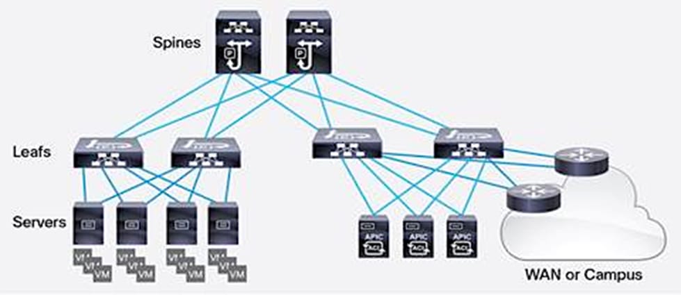
Architectural Building Blocks
The key architectural buildings blocks of the Cisco ACI fabric are:
· Application Policy Infrastructure Controller (APIC) - Cisco APIC is the unifying point of control in Cisco ACI for automating and managing the end-to-end data center fabric. The Cisco ACI fabric is built on a network of individual components that are provisioned and managed as a single entity. The APIC is a physical appliance that serves as a software controller for the overall fabric. It is based on Cisco UCS C-series rack mount servers with 2x10Gbps links for dual-homed connectivity to a pair of leaf switches and 1Gbps interfaces for out-of-band management. Cisco APIC optimizes the application lifecycle for scale and performance and supports flexible application provisioning across physical and virtual resources. The Cisco APIC exposes northbound APIs through XML and JSON and provides both a command-line interface (CLI) and GUI that manage the fabric through the same APIs available programmatically. For control plane resiliency, a cluster of three APICs, dual-homed to a pair of leaf switches in the fabric are typically deployed.
· Cisco Nexus 9000 Series Switches – The Cisco ACI fabric is built on a network of Cisco Nexus 9000 series switches that provide low-latency, high-bandwidth connectivity with industry proven protocols and innovative technologies to create a flexible, scalable, and highly available architecture. ACI is supported on several models of Nexus 9000 series switches and line cards. The selection of a Nexus 9000 series switch as an ACI spine or leaf switch will depend on a number of factors such as physical layer connectivity (1/10/25/40/50/100-Gbps), FEX aggregation support, analytics support in hardware (Cloud ASICs), FCoE support, link-level encryption, support for Multi-Pod, Multi-Site etc.
· Spine Nodes – The spines provide high-speed (40/100-Gbps) connectivity between leaf nodes. The ACI fabric forwards traffic by doing a host lookup in a mapping database that contains information about the leaf node where an endpoint (IP, Mac) resides. All known endpoints are maintained in a hardware database on the spine switches. The number of endpoints or the size of the database is a key factor in the choice of a Nexus 9000 model as a spine switch. Leaf switches also maintain a database but only for those hosts that send/receive traffic through it.
· Leaf Nodes – Leaf switches are essentially Top-of-Rack (ToR) switches that end devices connect into. They provide Ethernet connectivity to devices such as servers, firewalls, storage and other network elements. Leaf switches provide access layer functions such as traffic classification, policy enforcement, L2/L3 forwarding of edge traffic etc. The criteria for selecting a specific Nexus 9000 model as a leaf switch will be different from that of a spine switch.
For more information about Cisco ACI, see: https://www.cisco.com/c/en/us/products/cloud-systems-management/application-policy-infrastructure-controller-apic/index.html
Cisco Nexus 9000 Series Switch
The Cisco Nexus 9000 Series Switches offer both modular and fixed 10/40/100 Gigabit Ethernet switch configurations with scalability up to 60 Tbps of non-blocking performance with less than five-microsecond latency, wire speed VXLAN gateway, bridging, and routing support.
The Nexus featured in this design is the Nexus 9336C-FX2 implemented in NX-OS standalone mode (Figure 28).
![]()
The Nexus 9336C-FX2 implements Cisco Cloud Scale ASICs, giving flexible, and high port density, intelligent buffering, along with in-built analytics and telemetry. Supporting either Cisco ACI or NX-OS, the Nexus delivers a powerful 40/100Gbps platform offering up to 7.2 Tbps of bandwidth in a compact 1RU TOR switch.
For more information about the Cisco Nexus 9000 product family, see: https://www.cisco.com/c/en/us/products/switches/nexus-9000-series-switches/datasheet-listing.html
Cisco MDS 9000 Series Switch
The Cisco MDS 9000 family of multilayer switches give a diverse range of storage networking platforms, allowing you to build a highly scalable storage network with multiple layers of network and storage management intelligence. Fixed and modular models implement 2/4/8/10/16/32-32Gbps FC, 1/10/40*Gbps FCIP, 10/40GE FCoE, and up to 48 Tbps of switching bandwidth.
![]() * Refers to 40GE FCIP which is a future update.
* Refers to 40GE FCIP which is a future update.
The Cisco MDS 9132T Fibre Channel Fabric Switch is a 32-Gbps 32-Port Fibre Channel Switch provides Fibre Channel connectivity from the server rack to the SAN core. It empowers small, midsize, and large enterprises that are rapidly deploying cloud-scale applications using extremely dense virtualized servers, providing the dual benefits of greater bandwidth and consolidation. Small-scale SAN architectures can be built from the foundation using this low-cost, low-power, non-blocking, line-rate, and low-latency, bi-directional airflow capable, fixed standalone SAN switch connecting both storage and host ports. This switch also offers state-of-the-art SAN analytics and telemetry capabilities that have been built into this next-generation hardware platform using the built-in dedicated Network Processing Unit designed to complete analytics calculations in real time. The switch offers fully automated zoning feature called AutoZone. AutoZone can help create zones between each Initiator and Target automatically. Fully populated MDS 9132T can also provide higher number of buffer to buffer credits,4/8/16/32G FC connectivity, reversible airflow options, along with redundant PSUs and Fan Trays.
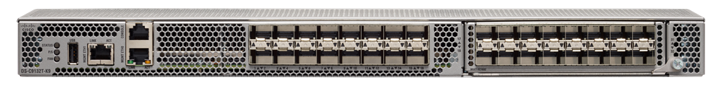
The Cisco MDS 9706 Multilayer Director is featured in this design as one of the options to use within an Adaptive Solutions for CI placement (Figure 31).
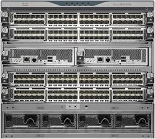
This six-slot switch presents a modular, redundant supervisor design, giving FC and FCoE line card modules, SAN extension capabilities, as well as NVMe over FC support on all ports. The MDS 9706 offers a lower TCO through SAN consolidation, high availability, traffic management, and packet level visibility using SAN analytics, along with management and monitoring capabilities available through Cisco Data Center Network Manager (DCNM).
For more information about the MDS 9000 product family, see: https://www.cisco.com/c/en/us/products/storage-networking/mds-9700-series-multilayer-directors/datasheet-listing.html
Cisco Data Center Network Manager
Cisco Data Center Network Manager (DCNM) provides configuration and operations management for both the MDS, UCS and Nexus lines of switches. Cisco Data Center Network Manager (Cisco DCNM) automates the infrastructure of Cisco Nexus 5000, 6000, 7000, and 9000 Series Switches and Cisco MDS 9000 Series switches for data center management. Cisco DCNM enables you to manage many devices while providing ready-to-use control, management, and automation capabilities, along with SAN Analytics and automation. It is optimized for large deployments with little overhead, but traditional deployments are supported as well for implementations. Fabric deployments can be customized by the user to meet business needs, delivering a range of features including SAN Telemetry, end-to-end topology views, and simplified zoning.
For more information about DCNM, see https://www.cisco.com/c/en/us/products/collateral/cloud-systems-management/prime-data-center-network-manager/datasheet-c78-740978.html
Hitachi Virtual Storage Platform
Hitachi Virtual Storage Platform is a highly scalable, true enterprise-class storage system that can virtualize external storage and provide virtual partitioning and quality of service for diverse workload consolidation. With the industry’s only 100 percent uptime warranty, Virtual Storage Platform delivers the highest uptime and flexibility for your block-level storage needs.
Hitachi Virtual Storage Platform F1500 and G1500
The all-flash Hitachi Virtual Storage Platform F1500 (VSP F1500) and the Hitachi Virtual Storage Platform G1500 (VSP G1500) storage systems provide high performance, high availability, and reliability for always-on, enterprise-class data centers. VSP F1500 and VSP G1500 deliver guaranteed data availability and feature the industry's most comprehensive suite of local and remote data protection capabilities, including true active-active metro-clustering. The storage systems scale to meet the demands of IT organizations’ ever-increasing workloads. When combined with server virtualization, the mission-critical storage virtualization supports a new breed of applications at cloud scale while reducing complexity.
Key features of the Hitachi Virtual Storage Platform F1500 and G1500 are:
· High-speed VSDs - VSP F1500 and G1500 are equipped with new virtual storage directors (VSDs) that use the latest generation of Intel Xeon 2.3-GHz 8-core microprocessor to efficiently manage the front-end and back-end directors, PCI-Express interface, shared memory, and service processor.
· All-flash VSP F1500 - The VSP F1500 all-flash storage system is configured exclusively with the latest generation of flash module drives (FMDs) to provide performance optimized for intense I/O operations. Designed for flash-first, high-performance workloads and leveraging Hitachi SVOS RF-based deduplication and compression, VSP F1500 offers up to five times greater ROI. Accelerated flash architecture delivers consistent, low-latency IOPS at scale. Adaptive flash management distributes writes and rebalances load over time, and FMDs from Hitachi deliver enterprise performance with superior functionality and greater cost value.
· Global Storage Virtualization - Enables an always-on infrastructure with enterprise-wide scalability that provides a complete separation between host and storage. The scalability is independent of connectivity, location, storage system, and vendor. Data center replication support allows provisioning and management of virtual storage machines up to 100 meters apart.
· Integrated Active Mirroring - Enables volume extensibility between systems and across sites through the provisioning and management of active-active volumes up to 100 km apart. Combined with remote data center replication, this mirroring is an ideal solution for critical applications that require zero recovery point and recovery time objectives. Active mirroring is enabled by the global-active device feature.
· Capacity Saving Functions – Data deduplication and data compression enable you to reduce the bitcost for stored data by deduplicating and compressing the data stored on internal flash drives. Data deduplication and compression are performed by the controllers of the storage system.
· Accelerated Compression - Enables you to reduce your bitcost for the stored data by utilizing the compression function in the flash module compression (FMC) drives. Accelerated compression allows you to assign FMC capacity to a pool that is larger than the physical capacity of the FMC parity groups. The data access performance of the storage system is maintained when the accelerated compression function is used, as the compression engine is offloaded to the FMC drives.
· Unified Storage with Enterprise Scalability - Allows you to centrally manage multi-vendor storage resources across all virtualized internal and external storage pools, whether deployed for SAN or object storage.
· Centralized Storage Management – Software such as Hitachi Storage Advisor simplifies administrative operations and streamlines basic management tasks.
· Hitachi Accelerated Flash - Offers a patented data center-class design and rack-optimized form factor that delivers up to 8.1 PB of HAF per system. It supports a sustained performance of 100,000 8K I/O operations per second per device, with fast and consistent response time.
· Server Virtualization - Integration with leading virtual server platforms provides end-to-end visibility, from an individual virtual machine to the storage logical unit, protecting large-scale multivendor environments.
· Customer-driven Nondisruptive Migration Capability - Enables movement, copy, and migration of data between storage systems, including non-Hitachi storage systems, without interrupting application access and local and remote copy relationships.
The VSP F1500 all-flash storage system is equipped with advanced high-density FMDs, providing up to 4M IOPS and 40 PB of capacity for multi-workload consolidation. Figure 32 shows a fully configured VSP G1500 with two controllers containing 8 virtual storage director (VSD) pairs (128 CPU cores), 2 TB cache, and 12 16U drive chassis containing 2,304 SFF drives with a physical storage capacity of approximately 2.7 PB.
Hitachi Virtual Storage Platform Fx00 Models and Gx00 Models
Based on Hitachi’s comprehensive suite of storage technology, the all-flash VSP F350, F370, F700, F900 and the VSP G350, G370, G700, and G900 include a range of versatile, high-performance storage systems that deliver flash-accelerated scalability, simplified management, and advanced data protection.
Hitachi Accelerated Flash (HAF) storage delivers best-in-class performance and efficiency in the Hitachi VSP F700, F900, G700, and G900 storage systems. HAF features patented flash module drives (FMDs) that are rack-optimized with a highly dense design that delivers greater than 338 TB effective capacity per 2U tray based on a typical 2:1 compression ratio. IOPS performance yields up to five times better results than that of enterprise solid-state drives (SSDs), resulting in leading performance, lowest bit cost, highest capacity, and extended endurance.
HAF integrated with Storage Virtualization Operating System (SVOS) RF running on VSP F700, F900, G700, and G900 enables transactions executed within sub-millisecond response even at petabyte scale.
For more information about Hitachi Virtual Storage Platform F Series, see: https://www.hitachivantara.com/en-us/products/storage/virtual-storage-platform-f-series.html
For more information about Hitachi Virtual Storage Platform G Series, see: https://www.hitachivantara.com/en-us/products/storage/virtual-storage-platform-g-series.html
Storage Virtualization Operating System RF
The Hitachi Storage Virtualization Operating System (SVOS) RF abstracts information from storage systems, virtualizes and pools available storage resources, and automates key data management functions such as configuration, mobility, optimization, and protection. This unified virtual environment enables you to maximize the utilization and capabilities of your storage resources while at the same time reducing operations overhead and risk. Standards-compatible for easy integration into IT environments, storage virtualization and management capabilities provide the utmost agility and control, helping you build infrastructures that are continuously available, automated, and agile. Hitachi VSP F350, F370, F700, F900, F1500, G350, G370, G700, G900, and G1500 all utilize SVOS RF as the operating system. This provides the same features and functionality across storage systems regardless of the size of the workloads or storage system.
SVOS RF is the latest version of SVOS. Flash performance is optimized with a patented flash-aware I/O stack, which accelerates data access. Adaptive inline data reduction increases storage efficiency while enabling a balance of data efficiency and application performance. Industry-leading storage virtualization allows SVOS RF to use third-party all-flash and hybrid systems as storage capacity, consolidating resources for a higher ROI and providing a high-speed front-end to slower, less predictable systems.
SVOS RF provides the foundation for superior storage performance, high availability, and IT efficiency. The enterprise-grade capabilities in SVOS RF include centralized management across storage systems and advanced storage features, such as active-active data centers and online migration between storage systems without user or workload disruption. Features of SVOS RF include:
· Advanced efficiency providing user-selectable data reduction
· External storage virtualization
· Thin provisioning and automated tiering
· Flash performance acceleration
· Deduplication and compression of data stored on internal flash drives
· Storage service-level controls
· Data-at-rest encryption
· Performance instrumentation across multiple storage platforms
· Centralized storage management
· Standards-based application program interfaces (REST APIs)
For more information about Hitachi Storage Virtualization Operating System RF, see: https://www.hitachivantara.com/en-us/products/storage/storage-virtualization-operating-system.html
Hitachi Storage Management
As an industry leading storage vendor, Hitachi has various integrations into VMware vSphere vCenter that will allow end users to seamlessly administer and deploy within their virtual environments. Within a Cisco UCS environment which utilizes Hitachi storage, users have multiple options when it comes to VMFS Datastore provisioning. Hitachi’s comprehensive list of tools will cover a different set of administrative needs:
Table 4 Hitachi Storage Management Software Capabilities
| Hitachi Storage Plug-in for VMware vCenter |
Hitachi Unified Compute Platform Advisor |
Hitachi Storage Provider for VMware vCenter (VASA) |
|
| Storage Creation |
|
|
|
| Create Datastore |
x |
x |
|
| Create a Logical Unit (LDEV) |
x |
x |
|
| Create Storage Pools (HDP/HDT) |
x |
||
| Create Parity Groups |
x |
||
| Create Host Groups |
x |
||
| Storage Deletion |
|||
| Delete Datastore |
x |
x |
|
| Delete Logical Unit (LDEV) |
x |
x |
|
| Delete Storage Pools (HDP/HDT) |
x |
||
| Delete Parity Groups |
x |
||
| Delete Host Groups |
x |
||
| Storage Expansion |
|||
| Expand Storage Pool (HDP/HDT) |
x |
||
| Expand Logical Unit (LDEV) |
x |
||
| Expand Datastore |
x |
||
| Storage Mapping |
|||
| Add LUN Path |
x |
x |
|
| Delete LUN Path |
x |
x |
|
| Storage View |
|||
| View VM Storage Info |
x |
||
| View Host Storage Info |
x |
||
| View Datastore Info |
x (Native UI) |
x (Plug-in UI) |
|
| View Storage System Info |
x |
||
| View Storage Ports Info |
x |
||
| View Storage Resource Group Info |
x |
||
| Storage Provider Capabilities |
|||
| Provide VVol Datastore |
x |
||
| Provide LDEV Datastore |
x |
Hitachi Storage Plug-in for VMware vCenter v03.10.0
The Hitachi Storage Plug-in for VMware vCenter enables VMware administrators to effortlessly deploy VMFS datastores within their native vCenter virtual environments.
The software requires access to RAID storage system controllers using TCP/IP, while ESXi servers must include TCP/IP or Fibre Channel connectivity to the storage systems. This guide is to only represent a fibre channel block-based storage configuration. Hitachi Storage Plug-in for VMware vCenter also supports Network File System (NFS) provisioning on the Hitachi Network Attach Storage (HNAS). Refer to Figure 33 for a visual representation.
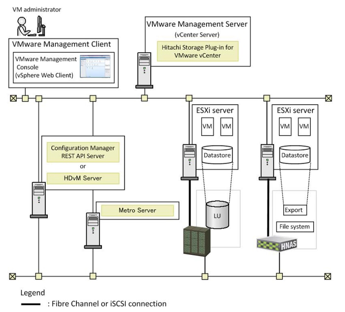
Depending on the storage system being used, you will need to create a Hitachi Configuration Manager server and onboard the storage system to be used within the Hitachi Storage Plugin for provisioning. For more information on how to deploy a Configuration Manager server and register a storage system using REST APIs. For more information on Configuration Manger Rest (CMrest) and Hitachi Storage API’s refer to:
· Hitachi Command Suite Configuration Manger REST API Reference Guide, MK-92HC229-10
With the Hitachi Storage Plugin organizations which have distinct operational roles for Storage and VMware administrators, where core Hitachi storage operations are performed by a Storage administrator, and core vSphere storage operations are performed by a vSphere administrator are made possible. The plugin allows easy mapping between Hitachi and VMware elements, enabling better communication between the two administrative groups through the VMware vSphere Web Client. Core features of the Hitachi Storage Plug-in are:
· View – Allows native Hitachi Storage information to be relayed up to VMware vCenter from vantage points which include datastore, ESXi host, and virtual machines.
· Provision VMFS Datastores - The Provision Datastore function creates a Logical Device used as a datastore for a Virtual Machine File System (VMFS) and Raw Device Mapping objects (RDMs) by a storage system registered with the Hitachi Storage Plug-in.
Hitachi Unified Compute Platform (UCP) Advisor v02.9.0
UCP Advisor is used in VMware based virtual environments through the FLEX client and requires ESXi hosts to have fibre channel connectivity to a SAN environment. UCP Advisor is provided via an OVA bundle which includes two UCP Advisor virtual machines.
· UCP Advisor Management Controller VM
· UCP Advisor Gateway OVA (AGW VM)
Once these machines are deployed within your virtual environment, you can register the UCP Advisor plugin to your VMware vCenter using the UCP Advisor ToolBox Windows application made available on the UCP Advisor Management VM. You must also map an Fibre channel command device (CMD) from the enterprise Hitachi storage system to the Advisor Gateway VM to be able to administer and utilize storage functionality within VMware vSphere. Figure 34 shows the system configuration of UCP Advisor.
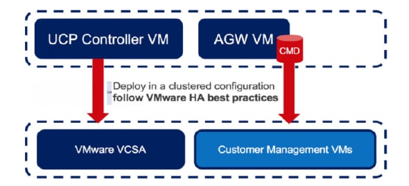
For more information regarding the deployment of UCP Advisor or RAID system command devices, refer to:
· Hitachi Unified Compute Platform (UCP) Advisor Deployment Guide, FE-92UCP098-09
· System Administrator Guide for VSP G130, G/F350, G/F370, G/F700, G/F900, MK-97HM85028-03
UCP advisor will allow administrators to have a single pane of glass for administration of multiple Hitachi Storage Systems. Once UCP Advisor is deployed within your environment you will have the ability to access the following feature sets:
· Datastore Provisioning - Creates a backend logical unit (LU), mounts the LU to host groups, and mounts VMFS datastores to your virtual environment. This can be done in a single operation using UCP Advisor.
· Parity Group Provisioning - Allows insight to available parity group resources within a RAID system and enables the creation of a parity group based on drive type and RAID level directly from the UCP Advisor plug-in.
· Logical Unit Provisioning - Admins can view all created LUs on the RAID subsystem even though they may have been provisioned by another storage management product. With UCP Advisor you can provision a new Logical Unit directly from the pools available on the storage system.
· Storage Pool Provisioning - With UCP Advisor administrators have the ability to carve various storage pools which include Hitachi Dynamic Provisioning (HDP), Hitachi Dynamic Tiered (HDT), and Hitachi Thin Image (HTI) pools.
· Host Group Provisioning - UCP Advisor allows administrators to create host groups directly from the plug-in UI.
· Deletion of Logical Devices (LUs) - Removes Logical Device on the RAID subsystem
· Deletion of Storage Pools - UCP Advisor allows the removal of Hitachi Dynamic Provision (HDP), Hitachi Dynamic Tired (HDT), and Hitachi Thin Image (HTI) pools.
· Deletion of Host Groups - Clears logical containers on the RAID system which correlates logical units to WWN initiators and targets.
· Deletion of Datastores - Unmounts/deletes VMFS datastore and removes back end logical unit on a RAID system.
· Removal of hosts and LUN paths from Host Groups - With UCP Advisor, administrators can remove host WWNs and Logical Unit LUN paths associated with a host group all from the native vCenter web client.
· Expansion of Storage Pools - Expands backend storage pool by adding available pool volumes to the pool.
· Expansion of Logical Unit backing datastore - Expands Logical Unit on the backend RAID subsystem supporting the VMFS datastore.
· Expansion of Existing Datastore - UCP Advisor automates the expansion of an existing datastore once the backend logical unit has been allocated additional capacity.
Hitachi Storage Provider for VMware vCenter v03.5.6
Hitachi Storage Provider for VMware vCenter allows VMware APIs for Storage Awareness (VASA) features to be used with Hitachi Storage Systems. VASA Provider allows policies to be made by making the storage attribute information available to be seen in vSphere. Hitachi VASA Provider makes this possible in the following two ways:
VMware vSphere Virtual Volumes (VVols)
VMware vSphere Virtual Volumes is a concept based on a new integration and management framework between vSphere and storage systems. It implements an out-of-band bidirectional control path through the VMware vSphere API for Storage Awareness (VASA)
Before VVols, VMFS was used to create a filesystem on top of block-based storage. Multiple VMs resided along with their files, VMDKs, in a single filesystem, making administration and analysis difficult. With the introduction of VVols, the ESXi operating system is now capable of talking directly to the storage and directly creating LUNs on the storage in a one-to-one basis so that each machine has a way of directly communicating with the storage.
In order to support this functionality, Hitachi Vantara has implemented storage policy-based management within Hitachi VASA provider. VASA can be used to specify storage attributes that will translate and become available to the VMware administrators inside vSphere. Characteristics can be based on cost, RAID, tier, pool type, and data protection capabilities.
VMware Virtual Machine File System (VMFS)
Hitachi VASA Provider also allows traditional VMFS environments to obtain storage attributes passed down by the storage administrator. This is made possible by taking advantage of tagging capabilities where customers can use Storage Policy Based Management (SPBM). Typically, LDEV capabilities are based on the underlying pool, but with Hitachi Vantara, VASA provider capabilities can be further customized by the administrator to include attributes such as cost, performance, or data location. This allows VMware administrators to understand what is made available to them within their virtual environments by their storage administrator.
With VVols, you need to present an Administrative Logical Unit, also known as a Protocol Endpoint (PE) to your ESXi hosts via the SAN fabric. VASA Provider is distributed as an OVF. Once you have VASA Provider deployed to your virtual environment, you can begin setting up the VASA Provider by onboarding a storage system. Once completed, you can setup VVol, and LDEV container attributes that are pushed down from the VASA provider to the native vSphere environment for the VMware administrator. VVols configurations were not covered within the deployment guide but have been validated for use within a Cisco UCS environment. For more information regarding the deployment and configuration of Hitachi VASA Provider, refer to:
· Hitachi Storage Provider for VMware vCenter Deployment Guide, MK-90ADPTR010-24
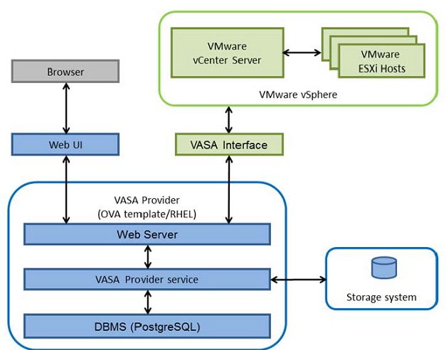
The benefits of the Hitachi Storage Provider are Increase visibility into storage services for a VM administrator. The ability to deliver granular quality of service (QoS) per virtual machine disk (VMDK) as opposed to per LUN for better performance management. As well as deliver differentiated data services to different tiers of a multitier VMs. For example, the database and log file of a multitier SQL VM can be placed on Tier 1 storage, while the operating system can be placed on Tier 2 storage resources for enhanced efficiency. And ultimately simplify the operational environment and automate the VM resource-provisioning process through policy-controlled automation, removing any possibility of error due to human intervention. Core features of the Hitachi storage Provider include
· VVol Datastore - Takes advantage of dedicated resource that is defined on a Hitachi RAID subsystem, in which policy driven storage management translated the capabilities to the VMware administrator.
· LDEV Datastore – Uses Storage Policy Based Management (SPBM) to push tags on common storage resources that is utilized within a typical virtual environment where the VMware administrator can understand the underlying capabilities based off location, cost, or drive type.
For more information about Hitachi Storage management products and how to use them within a VMware vSphere environment refer to the Hitachi Storage Management Software with Cisco UCS for VMware vSphere Best Practices Guide.
VMware Support
Hitachi VSP F series and G series are aligned with the VMware software-defined storage vision, providing the following support:
· vSphere Metro Storage Cluster (vMSC): Using Hitachi Global-active device (GAD), you can create and maintain synchronous, remote copies of data volumes. A virtual storage machine is configured in the primary and secondary storage systems using the actual information of the primary storage system, and the global-active device primary and secondary volumes are assigned the same virtual LDEV number in the virtual storage machine. This enables the host to see the pair volumes as a single volume on a single storage system, and both volumes receive the same data from the host. Configuring GAD as the backend storage for a vSphere Metro Storage Cluster provides an ideal solution for maximizing availability and uptime by clustering physical data centers that reside within metro distances of each other.
· Hitachi Storage Provider for VMware vCenter: Hitachi Storage Provider works with VMware vSphere API for Storage Awareness (VASA) to provide access to Hitachi VSP F series and G series. Storage Provider enables policy-based storage management using VMware Storage Policy-based Management (SPBM) and VMware Virtual Volumes (VVols). Storage Provider provides a simplified method for VMware admins and storage admins to deliver effective storage that meets advanced VM requirements.
· vSphere Storage APIs - Array Integration (VAAI): VAAI enables multiple storage functions (primitives) within vSphere to be offloaded to certified storage hardware. This reduces ESXi processor utilization by allowing certified storage hardware to perform these functions on the storage systems themselves. In many cases, VAAI accelerates these functions allowing them to complete in less time as compared to performing the functions within software on the ESXi host.
· Hitachi Storage Replication Adapter (SRA): Hitachi Storage Replication Adapter (SRA) for VMware Site Recovery Manager provides a disaster recovery (DR) solution that works with both your storage environment and your VMware environment. Arrays at both sites are "paired" during Site Recovery Manager configuration, and VMware administrators use the Site Recovery Manager application to manage the configuration and definition of the DR plan.
· vStorage API for Multipathing (VAMP): Hitachi VSP F series and G series support VAMP to provide enhanced control of I/O path selection and failover.
· vStorage API for Data Protection (VADP): Hitachi VSP F series and G series support VADP to enable backup applications to perform file-level or VM-level backup of running virtual machines.
Network and Management
Cisco Nexus 9000 Series Switches:
https://www.cisco.com/c/en/us/products/switches/nexus-9000-series-switches/datasheet-listing.html
Cisco Application Centric Infrastructure:
https://www.cisco.com/c/dam/en/us/solutions/collateral/data-center-virtualization/application-centric-infrastructure/solution-overview-c22-741487.pdf
Cisco MDS 9000 Series Multilayer Switches:
Cisco Data Center Network Manager 11:
Compute
Cisco Unified Computing System:
http://www.cisco.com/en/US/products/ps10265/index.html
Cisco UCS 6300 Series Fabric Interconnects:
Cisco UCS 6400 Series Fabric Interconnects:
Cisco UCS 5100 Series Blade Server Chassis:
Cisco UCS 2300 Series Fabric Extenders:
Cisco UCS 2200 Series Fabric Extenders:
https://www.cisco.com/c/en/us/products/collateral/servers-unified-computing/ucs-6300-series-fabric-interconnects/data_sheet_c78-675243.html
Cisco UCS B-Series Blade Servers:
http://www.cisco.com/en/US/partner/products/ps10280/index.html
Cisco UCS VIC 1440 Adapter:
Cisco UCS Manager:
http://www.cisco.com/en/US/products/ps10281/index.html
Storage
Data Protection with Hitachi Ops Center Protector on Cisco and Hitachi Adaptive Solutions:
Hitachi Virtual Storage Platform F Series:
Hitachi Virtual Storage Platform G Series:
Virtualization Layer
VMware vCenter Server:
http://www.vmware.com/products/vcenter-server/overview.html
VMware vSphere:
https://www.vmware.com/products/vsphere
Compatibility Matrixes
Cisco UCS Hardware Compatibility Matrix:
https://ucshcltool.cloudapps.cisco.com/public/
Cisco Nexus Recommended Releases for Nexus 9K:
Cisco MDS Recommended Releases:
Cisco Nexus and MDS Interoperability Matrix:
Cisco MDS 9000 Family Pluggable Transceivers Data Sheet:
Hitachi Interoperability:
https://support.hitachivantara.com/en_us/interoperability.html sub-page -> (VSP G1X00, F1500, Gxx0, Fxx0, VSP, HUS VM VMWare Support Matrix)
VMware and Cisco Unified Computing System:
http://www.vmware.com/resources/compatibility
Ramesh Isaac, Technical Marketing Engineer, Cisco Systems, Inc.
Ramesh Isaac is a Technical Marketing Engineer in the Cisco UCS Data Center Solutions Group. Ramesh has worked in the data center and mixed-use lab settings since 1995. He started in information technology supporting UNIX environments and focused on designing and implementing multi-tenant virtualization solutions in Cisco labs before entering Technical Marketing where he has supported converged infrastructure and virtual services as part of solution offerings as Cisco. Ramesh has certifications from Cisco, VMware, and Red Hat.
Arvin Jami, Virtualization Solution Architect, Hitachi Vantara
Arvin Jami began his career at Hitachi Data Systems as an intern in 2014. Since then he has held the position of Technical Marketing Engineer where he demonstrated and positioned Hitachi products to fortune 500 companies. He is now the Virtualization Solution Architect in the Hitachi Vantara Converged Product Engineering Group. Arvin has a Bachelor of Science degree in Electrical Engineering from San Jose State University.
Acknowledgements
For their support and contribution to the design, validation, and creation of this Cisco Validated Design, the authors would like to thank:
· Haseeb Niazi, Technical Marketing Engineer, Cisco Systems, Inc.
· Archana Sharma, Technical Marketing Engineer, Cisco Systems, Inc.
· Tim Darnell, Master Solutions Architect and Product Owner, Hitachi Vantara
 Feedback