Cisco and Hitachi Adaptive Solutions for Converged Infrastructure with Cisco ACI
Available Languages

Cisco and Hitachi Adaptive Solutions for Converged Infrastructure with Cisco ACI
Deployment Guide for Cisco and Hitachi Adaptive Solutions with ACI 4.1 and VMware vSphere 6.7 for Single Site Deployment
Last Updated: September 17, 2019
About the Cisco Validated Design Program
The Cisco Validated Design (CVD) program consists of systems and solutions designed, tested, and documented to facilitate faster, more reliable, and more predictable customer deployments. For more information, go to:
http://www.cisco.com/go/designzone.
ALL DESIGNS, SPECIFICATIONS, STATEMENTS, INFORMATION, AND RECOMMENDATIONS (COLLECTIVELY, "DESIGNS") IN THIS MANUAL ARE PRESENTED "AS IS," WITH ALL FAULTS. CISCO AND ITS SUPPLIERS DISCLAIM ALL WARRANTIES, INCLUDING, WITHOUT LIMITATION, THE WARRANTY OF MERCHANTABILITY, FITNESS FOR A PARTICULAR PURPOSE AND NONINFRINGEMENT OR ARISING FROM A COURSE OF DEALING, USAGE, OR TRADE PRACTICE. IN NO EVENT SHALL CISCO OR ITS SUPPLIERS BE LIABLE FOR ANY INDIRECT, SPECIAL, CONSEQUENTIAL, OR INCIDENTAL DAMAGES, INCLUDING, WITHOUT LIMITATION, LOST PROFITS OR LOSS OR DAMAGE TO DATA ARISING OUT OF THE USE OR INABILITY TO USE THE DESIGNS, EVEN IF CISCO OR ITS SUPPLIERS HAVE BEEN ADVISED OF THE POSSIBILITY OF SUCH DAMAGES.
THE DESIGNS ARE SUBJECT TO CHANGE WITHOUT NOTICE. USERS ARE SOLELY RESPONSIBLE FOR THEIR APPLICATION OF THE DESIGNS. THE DESIGNS DO NOT CONSTITUTE THE TECHNICAL OR OTHER PROFESSIONAL ADVICE OF CISCO, ITS SUPPLIERS OR PARTNERS. USERS SHOULD CONSULT THEIR OWN TECHNICAL ADVISORS BEFORE IMPLEMENTING THE DESIGNS. RESULTS MAY VARY DEPENDING ON FACTORS NOT TESTED BY CISCO.
CCDE, CCENT, Cisco Eos, Cisco Lumin, Cisco Nexus, Cisco StadiumVision, Cisco TelePresence, Cisco WebEx, the Cisco logo, DCE, and Welcome to the Human Network are trademarks; Changing the Way We Work, Live, Play, and Learn and Cisco Store are service marks; and Access Registrar, Aironet, AsyncOS, Bringing the Meeting To You, Catalyst, CCDA, CCDP, CCIE, CCIP, CCNA, CCNP, CCSP, CCVP, Cisco, the Cisco Certified Internetwork Expert logo, Cisco IOS, Cisco Press, Cisco Systems, Cisco Systems Capital, the Cisco Systems logo, Cisco Unified Computing System (Cisco UCS), Cisco UCS B-Series Blade Servers, Cisco UCS C-Series Rack Servers, Cisco UCS S-Series Storage Servers, Cisco UCS Manager, Cisco UCS Management Software, Cisco Unified Fabric, Cisco Application Centric Infrastructure, Cisco Nexus 9000 Series, Cisco Nexus 7000 Series. Cisco Prime Data Center Network Manager, Cisco NX-OS Software, Cisco MDS Series, Cisco Unity, Collaboration Without Limitation, EtherFast, EtherSwitch, Event Center, Fast Step, Follow Me Browsing, FormShare, GigaDrive, HomeLink, Internet Quotient, IOS, iPhone, iQuick Study, LightStream, Linksys, MediaTone, MeetingPlace, MeetingPlace Chime Sound, MGX, Networkers, Networking Academy, Network Registrar, PCNow, PIX, PowerPanels, ProConnect, ScriptShare, SenderBase, SMARTnet, Spectrum Expert, StackWise, The Fastest Way to Increase Your Internet Quotient, TransPath, WebEx, and the WebEx logo are registered trademarks of Cisco Systems, Inc. and/or its affiliates in the United States and certain other countries.
All other trademarks mentioned in this document or website are the property of their respective owners. The use of the word partner does not imply a partnership relationship between Cisco and any other company. (0809R)
© 2019 Cisco Systems, Inc. All rights reserved.
Table of Contents
Deployment Hardware and Software
Hardware and Software Versions
Cisco Application Policy Infrastructure Controller (APIC) Verification
Initial ACI Fabric Setup Verification
Set Up Out-of-Band Management IP Addresses for New Leaf Switches
Verify Time Zone and NTP Server
Verify Fabric Wide Enforce Subnet Check for IP and MAC Learning
Create LLDP Interface Policies
Create BPDU Filter/Guard Policies
Create Virtual Port Channels (vPCs)
vPC – Cisco UCS Fabric Interconnects
Deploy Shared Layer 3 Connectivity to Outside Networks – Pod-1
Create VLAN Pool for External Routed Domain
Configure Domain Type for External Routed Domain
Create AAEP for External Routed Domain
Configure Interfaces to External Routed Domain
Configure Tenant Networking for Shared L3Out
Configure External Routed Networks under Tenant Common
Create Contracts for External Routed Networks from Tenant (common)
Provide Contracts for External Routed Networks from Tenant (common)
Configure External Gateways in the Outside Network
Create Application Profile for Infrastructure
Create Application Profile for Host Connectivity
Initial MDS Configuration Dialogue
Cisco MDS Switch Configuration
Create Port Descriptions - Fabric B
Configure Fibre Channel Ports on Hitachi Virtual Storage Platform
Cisco UCS Compute Configuration
Upgrade Cisco UCS Manager Software to Version 4.0(4b)
Enable Port Auto-Discovery Policy
Enable Info Policy for Neighbor Discovery
Enable Server and Uplink Ports
Configure Cisco UCS LAN Connectivity
Set Jumbo Frames in Cisco UCS Fabric
Create LAN Connectivity Policy
Create SAN Connectivity Policy
Create Service Profile Template
Create vMedia Service Profile Template
Collect UCS Host vHBA Information for Zoning
DCNM Switch Registration and Zoning(Optional)
Connect to DCNM and Registering Switches
Configuring Device Aliases for the VSP and ESXi hosts
Configure Host Connectivity and Presentation for Storage on Hitachi Virtual Storage Platform
Create a Hitachi Dynamic Provisioning Pool for UCS Server Boot LDEVs
Create a Hitachi Dynamic Provisioning Pool for UCS Server VMFS Volume LDEVs
Create Host Groups for Cisco UCS Server vHBAs on Each Fabric
Create Boot LDEVs for Each UCS Service Profile and Add LDEV Paths
Create Shared VMFS LDEVs and Add LDEV Paths
Download Cisco Custom Image for ESXi 6.7 U2
Log into Cisco UCS 6454 Fabric Interconnect
Set Up VMware ESXi Installation
Set Up Management Networking for ESXi Hosts
Log into VMware ESXi Hosts by Using VMware Host Client
Set Up VMkernel Ports and Virtual Switch
Add Provisioned Datastore to Configured Hosts
Build the VMware vCenter Server Appliance (optional)
Add the VMware ESXi Hosts Using the VMware vSphere Web Client
Create and Apply Patch Baselines with VUM
Allocate VMFS Datastore using Hitachi Storage Plug-in for VMware vCenter
Allocate VMFS datastore using Hitachi Unified Compute Platform Advisor
Allocate VMFS Datastore using Hitachi Storage Provider for VMware vCenter (LDEV Storage Type)
Remediation of L1 Terminal Fault – VMM (L1TF) Security Vulnerability (Optional)
ACI Integration with Cisco UCS and vSphere
Cisco ACI vCenter Plug-in Installation
Create Virtual Machine Manager (VMM) Domain in APIC
Create an Application Tenant with the Cisco ACI vCenter Plugin
Appendix: MDS Device Alias and Zoning through CLI
Appendix: MDS Example startup-configuration File
Appendix – Cisco Workload Optimization Manager
Cisco Workload Optimization Manager Setup
Install Workload Optimization Manager
Initial Cisco Workload Optimization Manager Setup
License Installation and First Time Login
Cisco Validated Designs (CVDs) consist of systems and solutions that are designed, tested, and documented to facilitate and improve customer deployments. These designs incorporate a wide range of technologies and products into a portfolio of solutions that have been developed to address the business needs of our customers.
Cisco and Hitachi are working together to deliver a converged infrastructure solution that helps enterprise businesses meet the challenges of today and position themselves for the future. This CVD utilizes many of the same components as the initial Cisco and Hitachi Adaptive Solutions architecture but has been reimplemented to take advantage of the Cisco Application Centric Infrastructure (ACI).
Cisco ACI is a holistic architecture that introduces hardware and software innovations built upon the Cisco Nexus 9000® Series product line. Cisco ACI provides a centralized policy-driven application deployment architecture that is managed through the Cisco Application Policy Infrastructure Controller (APIC). Cisco ACI delivers software flexibility with the scalability of hardware performance.
This document steps through the deployment of the Cisco and Hitachi Adaptive Solutions for Converged Infrastructure as a Virtual Server Infrastructure (VSI) using Cisco ACI. This architecture is described in the Cisco and Hitachi Adaptive Solutions for Converged Infrastructure with ACI Design Guide. The recommended solution architecture is built on Cisco Unified Computing System (Cisco UCS) using the unified software release to support the Cisco UCS hardware platforms for the Cisco UCS B-Series Blade Server, Cisco UCS 6400 or 6300 Fabric Interconnects, Cisco Nexus 9000 Series switches, Cisco MDS 9000 Multilayer switches, and Hitachi Virtual Storage Platform (VSP).
Introduction
Modernizing your data center can be overwhelming, and it’s vital to select a trusted technology partner with proven expertise. With Cisco and Hitachi as partners, companies can build for the future by enhancing systems of record, supporting systems of innovation, and growing their business. Organizations need an agile solution, free from operational inefficiencies, to deliver continuous data availability, meet SLAs, and prioritize innovation.
Hitachi and Cisco Adaptive Solutions for Converged Infrastructure as a Virtual Server Infrastructure (VSI) is a best practice datacenter architecture built on the collaboration of Hitachi Vantara and Cisco to meet the needs of enterprise customers utilizing virtual server workloads. This architecture has been expanded to include the Cisco Application Centric Infrastructure (ACI) as an overarching SDN solution. Under the ACI umbrella, the Hitachi Virtual Storage Platform (VSP) connects through the Cisco MDS Multilayer Switch to the Cisco Unified Computing System (Cisco UCS) and is enabled within the network using the same Cisco Nexus family of switches.
The reference architecture covers specifics of products utilized within the Cisco validation lab, but the solution is considered relevant for equivalent supported components listed within Cisco and Hitachi Vantara’s published compatibility matrixes. Supported adjustments from the example validated build must be evaluated with care as their implementation instructions may differ.
Audience
The audience for this document includes, but is not limited to; sales engineers, field consultants, professional services, IT managers, partner engineers, and customers who want to modernize their infrastructure to meet SLAs and their business needs at any scale.
Purpose of this Document
This document provides a step by step configuration and implementation guide for the Cisco and Hitachi Adaptive Solutions for Converged Infrastructure solution configured with Cisco ACI 4.1. This solution features a validated reference architecture composed of:
· Cisco UCS Compute
· Cisco Nexus Switches with ACI
· Cisco MDS Multilayer Fabric Switches
· Hitachi Virtual Storage Platform
The design and technology decisions that went into this solution can be found in the accompanying Cisco and Hitachi Adaptive Solutions with Cisco ACI Design Guide.
What’s New in this Release?
The following design uses many of the concepts and best practices of the initial release, but in this release the primary differentiators are:
· Support for Cisco ACI 4.1
· Support for the Intel Cascade Lake Processors within Cisco UCS B200 M5 servers
· Support for Hitachi UCP Advisor
Architecture
Cisco and Hitachi Adaptive Solutions for Converged Infrastructure is a validated reference architecture targeting Virtual Server Infrastructure (VSI) implementations. The architecture is built around the Cisco Unified Computing System (Cisco UCS) and the Hitachi Virtual Storage Platform (VSP) connected together by Cisco MDS Multilayer SAN Switches, and in this release, designed with the Cisco Application Centric Infrastructure using Cisco Nexus Switches.
These components come together to form a powerful and scalable design, built on the best practices of both companies to create an ideal environment for virtualized systems.
The solution is built and validated for a topology featuring the Cisco UCS Fabric Interconnect as well as the Hitachi VSP Storage System, using the MDS and the Nexus switching infrastructure which is implemented with Cisco ACI. The topology, shown in Figure 1:
· Cisco Nexus 93180YC-FX – 100Gb capable ACI leaves, giving LAN connectivity to the UCS compute resources.
· Cisco Nexus 9364C ACI spines, delivering the backbone of the upstream network.
· Cisco Application Policy Infrastructure Controllers, management servers for the ACI SDN implementation, giving API, CLI, and GUI options as an interface.
· Cisco UCS 6454 Fabric Interconnect – Unified management of UCS compute, and the compute’s access to storage and networks.
· Cisco UCS B200 M5 – High powered, versatile blade server, with IntelÒ Cascade Lake processors.
· Cisco MDS 9706 – 32Gbps Fibre Channel connectivity within the architecture, as well as interfacing to resources present in an existing data center.
· Hitachi VSP G370 – Mid-range, high performance storage system with optional all-flash configuration
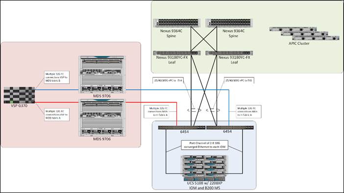 The Cisco UCS B200 M5 servers in this topology are hosted within the same Cisco UCS 5108 Chassis but connect into the fabric interconnects from the chassis using Cisco UCS 2208XP IOMs. The 2208XP IOM supports up to 8 10G connections going into the Cisco UCS 6454 FIs, delivering a high bandwidth solution for either remote office or the corporate datacenter.
Management components for both architectures additionally include:
· Cisco UCS Manager – Management delivered through the Fabric Interconnect, providing stateless compute, and policy driven implementation of the servers managed by it.
· Cisco Intersight (optional) – Comprehensive unified visibility across UCS domains, along with proactive alerts and enablement of expedited Cisco TAC communications.
· Cisco Data Center Network Manager (optional) – Multi-layer network configuration and monitoring.
· Cisco Workload Optimization Manager (optional) – Resource optimization to deliver capex savings.
· Hitachi Storage Navigator – Management of Storage Virtualization Operating System (SVOS) on the VSP storage platform.
· Hitachi UCP Advisor (optional) – Comprehensive visibility and provisioning of VSP storage through vCenter.
The validation lab covered the above topology, as well as management components listed within a vSphere 6.7 U2 based hypervisor environment. vSphere 6.5 was not validated but is supported within the Cisco-Hitachi Interoperability partnership.
Hardware and Software Versions
Table 1 lists the validated hardware and software versions used for this solution. Configuration specifics are given in this deployment guide for the devices and versions listed in the following tables. Component and software version substitution from what is listed is considered acceptable within this reference architecture, but substitution will need to comply with the hardware and software compatibility matrices from both Cisco and Hitachi.
Cisco UCS Hardware Compatibility Matrix:
https://ucshcltool.cloudapps.cisco.com/public/
Cisco Nexus and MDS Interoperability Matrix:
Recommended Cisco APIC and Cisco Nexus 9000 Series ACI-Mode Switches Releases:
Cisco ACI Virtualization Compatibility Matrix:
Hitachi Vantara Interoperability:
https://support.hitachivantara.com/en_us/interoperability.html
In addition, any substituted hardware or software may have different configurations from what is detailed in this guide and will require a thorough evaluation of the substituted product reference documents.
Table 1 Validated Hardware and Software
| Component |
Software Version/Firmware Version |
|
| Network |
Cisco Nexus 93180YC-FX (leaf) |
14.1(2g) |
| Cisco Nexus 9364C (spine) |
14.1(2g) |
|
| Cisco APIC M2 |
4.1(2g) |
|
| Cisco ExternalSwitch |
1.0 |
|
| Cisco ACI Plugin |
4.1.2000.7 |
|
| Compute |
Cisco UCS Fabric Interconnect 6454 |
4.0(4b) |
| Cisco UCS 2208XP IOM |
4.0(4b) |
|
| Cisco UCS B200 M5 |
4.0(4b) |
|
| VMware vSphere |
6.7 U2 VMware_ESXi_6.7.0_13006603_Custom_Cisco_6.7.2.1.iso |
|
| ESXi 6.7 U2 nenic |
1.0.29.0 |
|
| ESXi 6.7 U2 nfnic |
4.0.0.38 |
|
| VMware vCenter Server Appliance |
6.7 U2 |
|
| VM Virtual Hardware Version |
13 |
|
| Storage |
Hitachi VSP G370 |
88-03-23 (SVOS 8.3.1) |
| Hitachi UCP Advisor |
3.0 |
|
| Hitachi Storage Plugin for vCenter |
3.10.0 |
|
| Hitachi Storage Provider for VMware vCenter (VASA) |
3.5.6 |
|
| Cisco MDS 9706 |
8.3(1) |
|
| Cisco DCNM |
11.2(1) |
|
Configuration Guidelines
This document provides details for configuring a fully redundant, highly available configuration for the Cisco and Hitachi Converged Infrastructure. References are made to which component is being configured with each step, either “-1” or “-2”. For example, AA19-9706-1 and AA19-9706-2 are used to identify the two MDS switches that are provisioned with this document, with AA19-9706-1 and 2 used to represent a command invoked on both Nexus switches. The Cisco UCS fabric interconnects are similarly configured. Additionally, this document details the steps for provisioning multiple Cisco UCS hosts, and these examples are identified as: VM-Host-Infra-01, VM-Host-Infra-02 to represent hosts deployed to each of the fabric interconnects in this document. Finally, to indicate that you should include information pertinent to your environment in a given step, <text> appears as part of the command structure.
See the following example of a configuration step for both Nexus switches:
AA19-9706-1&2 (config)# ntp server <<var_oob_ntp>>
This document is intended to enable you to fully configure the customer environment. In this process, various steps require you to insert customer-specific naming conventions, IP addresses, and VLAN schemes, as well as to record appropriate MAC addresses. The tables provided can be copied or printed for use as a reference to align the appropriate customer deployed values for configuration specifics used within the guide.
Table 2 lists the VLANs necessary for deployment as outlined in this guide.
Table 2 VLANs Used in the Deployment
| VLAN Name |
VLAN Purpose |
ID Used in Validating this Document |
Customer Deployed Value |
| Internal-Infra |
VLAN for Internal Infrastructure (UCSM/VSP) |
119 |
|
| Common |
VLAN for Shared Infrastructure (AD/DNS) |
319 |
|
| Host-Mgmt |
VLAN for Hypervisor Hosts (ESXi) |
419 |
|
| vMotion |
VLAN for vSphere vMotion traffic |
519 |
|
| Native |
VLAN to which untagged frames are assigned |
2 |
|
| App-vDS-[1-100] |
VLAN for Application VM Interfaces residing in vDS based port groups |
1100-1199 |
|
Table 3 lists additional configuration variables are used throughout the document as pointers to where a customer provided name, or reference for relevant existing information will be used.
Table 3 Variables for Information Used in the Design
| Variable |
Variable Description |
Customer Deployed Value |
| <<var_nexus_A_hostname>> |
Nexus switch A hostname (Example: AA20-93180-1) |
|
| <<var_nexus_A_mgmt_ip>> |
Out-of-band management IP for Nexus switch A (Example: 172.16.163.108) |
|
| <<var_nexus_B_hostname>> |
Nexus switch B hostname (Example: AA20-93180-2) |
|
| <<var_nexus_B_mgmt_ip>> |
Out-of-band management IP for Nexus switch B (Example: 172.26.163.109) |
|
| <<var_oob_mgmt_mask>> |
Out-of-band management network netmask (Example: 255.255.255.0) |
|
| <<var_oob_gateway>> |
Out-of-band management network gateway (Example: 172.26.163.254) |
|
| <<var_oob_ntp>> |
Out-of-band management network NTP server (Example: 172.26.163.254) |
|
| <<var_password>> |
Administrative password (Example: N0taP4ss) |
|
| <<var_dns_domain_name>> |
DNS domain name (Example: ucp.cisco.com) |
|
| <<var_nameserver_ip>> |
DNS server IP(s) (Example: 10.1.168.9) |
|
| <<var_timezone>> |
Time zone (Example: America/New_York) |
|
| <<var_ib_mgmt_vlan_id>> |
In-band (Site Infra) management network VLAN ID (Example: 119) |
|
| <<var_ib_mgmt_vlan_netmask_length>> |
Length of Site-Infra-VLAN Netmask (Example: /24) |
|
| <<var_ib_gateway_ip>> |
Site Infra management network VLAN ID (Example: 10.1.168.254) |
|
| <<var_vmotion_vlan_id>> |
vMotion management network VLAN ID (Example: 519) |
|
| <<var_vmotion_vlan_netmask_length>> |
Length of vMotion-VLAN Netmask (Example: /24) |
|
| <<var_vsan_a_id>> |
VSAN used for the A Fabric between the VSP /FI (Example: 101) |
|
| <<var_vsan_b_id>> |
VSAN used for the A Fabric between the VSP /FI (Example: 102) |
|
| <<vsp_hostname>> <<vsp-g370>> |
Hitachi VSP storage system name (Example g370-[Serial Number]) |
|
| <<var_ucs_clustername>> <<var_ucs_6454_clustername>> |
Cisco UCS Manager cluster host name (Example: AA19-6454) |
|
| <<var_ucsa_mgmt_ip>> |
Cisco UCS fabric interconnect (FI) A out-of-band management IP address (Example: 10.1.168.16) |
|
| <<var_ucs_mgmt_vip>> |
Cisco UCS fabric interconnect (FI) Cluster out-of-band management IP address (Example: 10.1.168.15) |
|
| <<var_ucsb_mgmt_ip>> |
Cisco UCS FI B out-of-band management IP address (Example: 10.1.168.17) |
|
| <<var_vm_host_infra_01_ip>> |
VMware ESXi host 01 in-band management IP (Example: 10.4.168.21) |
|
| <<var_vm_host_infra_02_ip>> |
VMware ESXi host 02 in-band management IP (Example: 10.4.168.22) |
|
| <<var_vm_host_infra_vmotion_01_ip>> |
VMware ESXi host 01 vMotion IP (Example: 192.168.100.21) |
|
| <<var_vm_host_infra_vmotion_02_ip>> |
VMware ESXi host 02 vMotion IP (Example: 192.168.100.22) |
|
| <<var_vmotion_subnet_mask>> |
vMotion subnet mask (Example: 255.255.255.0) |
|
| <<var_vcenter_server_ip>> |
IP address of the vCenter Server (Example: 10.168.168.100) |
|
Physical Cabling
This section explains the cabling examples used for the validated topology in the environment. To make connectivity clear in this example, the tables include both the local and remote port locations.
Physical Cabling for the UCS 6454 with the VSP G370
Figure 2 shows the cabling configuration used in the design featuring the Cisco UCS 6454 FI with the Hitachi VSP G370.
Figure 2 Cisco UCS 6454 and VSP G370 with ACI Cabling Diagram
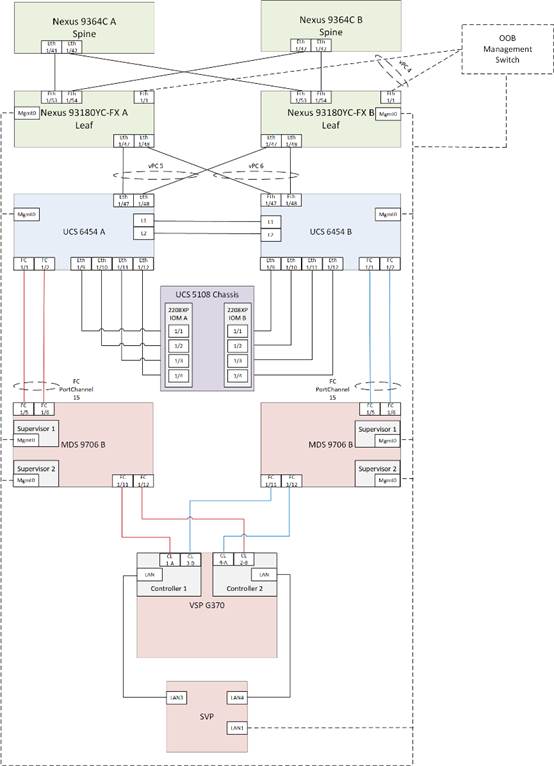
The following tables list the specific port connections with the cables used in the deployment of the Cisco UCS 6454 and the VSP G370 are provided below.
Table 4 Cisco Nexus 93180YC-FX A (Leaf) Cabling Information
| Local Device |
Local Port |
Connection |
Remote Device |
Remote Port |
| Cisco Nexus 93180YC-FX A
|
Eth1/1 |
GbE |
GbE management switch |
any |
| Eth1/47 |
25GbE |
Cisco UCS 6454 FI A |
Eth1/47 |
|
| Eth1/48 |
25GbE |
Cisco UCS 6454 FI B |
Eth 1/47 |
|
| Eth1/53 |
40GbE or 100GbE |
Cisco 9364C A (Spine) |
Eth 1/41 |
|
| Eth1/54 |
40GbE or 100GbE |
Cisco 9364C B (Spine) |
Eth 1/41 |
|
| MGMT0 |
GbE |
GbE management switch |
Any |
Table 5 Cisco Nexus 93180YC-FX B (Leaf) Cabling Information
| Local Device |
Local Port |
Connection |
Remote Device |
Remote Port |
| Cisco Nexus 93180YC-FX B
|
Eth1/1 |
GbE |
GbE management switch |
any |
| Eth1/47 |
25GbE |
Cisco UCS 6454 FI A |
Eth1/48 |
|
| Eth1/48 |
25GbE |
Cisco UCS 6454 FI B |
Eth 1/48 |
|
| Eth1/53 |
40GbE or 100GbE |
Cisco 9364C A (Spine) |
Eth 1/42 |
|
| Eth1/54 |
40GbE or 100GbE |
Cisco 9364C B (Spine) |
Eth 1/42 |
|
| MGMT0 |
GbE |
GbE management switch |
Any |
Table 6 Cisco UCS 6454 A Cabling Information
| Local Device |
Local Port |
Connection |
Remote Device |
Remote Port |
| Cisco UCS 6454 FI A |
FC 1/1 |
32Gb FC |
MDS 9706 A |
FC 1/5 |
| FC 1/2 |
32Gb FC |
MDS 9706 A |
FC 1/6 |
|
| Eth1/9 |
10GbE |
Cisco UCS Chassis 2208XP FEX A |
IOM 1/1 |
|
| Eth1/10 |
10GbE |
Cisco UCS Chassis 2208XP FEX A |
IOM 1/2 |
|
| Eth1/11 |
10GbE |
Cisco UCS Chassis 2208XP FEX A |
IOM 1/3 |
|
| Eth1/12 |
10GbE |
Cisco UCS Chassis 2208XP FEX A |
IOM 1/4 |
|
| Eth1/47 |
25GbE |
Cisco Nexus 93180YC-FX A |
Eth1/47 |
|
| Eth1/48 |
25GbE |
Cisco Nexus 93180YC-FX B |
Eth1/47 |
|
| MGMT0 |
GbE |
GbE management switch |
Any |
|
| L1 |
GbE |
Cisco UCS 6454 FI B |
L1 |
![]() Ports 1-8 on the Cisco UCS 6454 are unified ports that can be configured as Ethernet or as Fibre Channel ports. Server ports should be initially deployed started with 1/9 to give flexibility for FC port needs, and ports 49-54 are not configurable for server ports. Also, ports 45-48 are the only configurable ports for 1Gbps connections that may be needed to a network switch.
Ports 1-8 on the Cisco UCS 6454 are unified ports that can be configured as Ethernet or as Fibre Channel ports. Server ports should be initially deployed started with 1/9 to give flexibility for FC port needs, and ports 49-54 are not configurable for server ports. Also, ports 45-48 are the only configurable ports for 1Gbps connections that may be needed to a network switch.
Table 7 Cisco UCS 6454 B Cabling Information
| Local Device |
Local Port |
Connection |
Remote Device |
Remote Port |
| Cisco UCS 6454 FI B
|
FC 1/1 |
32Gb FC |
MDS 9706 B |
FC 1/5 |
| FC 1/2 |
32Gb FC |
MDS 9706 B |
FC 1/6 |
|
| Eth1/9 |
10GbE |
Cisco UCS Chassis 2208XP FEX B |
IOM 1/1 |
|
| Eth1/10 |
10GbE |
Cisco UCS Chassis 2208XP FEX B |
IOM 1/2 |
|
| Eth1/11 |
10GbE |
Cisco UCS Chassis 2208XP FEX B |
IOM 1/3 |
|
| Eth1/12 |
10GbE |
Cisco UCS Chassis 2208XP FEX B |
IOM 1/4 |
|
| Eth1/47 |
25GbE |
Cisco Nexus 93180YC-FX A |
Eth1/48 |
|
| Eth1/48 |
25GbE |
Cisco Nexus 93180YC-FX B |
Eth1/48 |
|
| MGMT0 |
GbE |
GbE management switch |
Any |
|
| L1 |
GbE |
Cisco UCS 6454 FI A |
L1 |
|
| L2 |
GbE |
Cisco UCS 6454 FI A |
L2 |
Table 8 Cisco MDS 9706 A Cabling Information
| Local Device |
Local Port |
Connection |
Remote Device |
Remote Port |
| Cisco MDS 9706 A
|
FC 1/5 |
32Gb FC |
Cisco UCS 6454 FI A |
FC 1/1 |
| FC 1/6 |
32Gb FC |
Cisco UCS 6454 FI A |
FC 1/2 |
|
| FC 1/11 |
32Gb FC |
VSP G370 Controller 1 |
CL 1-A |
|
| FC 1/12 |
32Gb FC |
VSP G370 Controller 2 |
CL 2-B |
|
| Sup1 MGMT0 |
GbE |
GbE management switch |
Any |
|
| Sup2 MGMT0 |
GbE |
GbE management switch |
Any |
Table 9 Cisco MDS 9706 B Cabling Information
| Local Device |
Local Port |
Connection |
Remote Device |
Remote Port |
| Cisco MDS 9706 B
|
FC 1/5 |
32Gb FC |
Cisco UCS 6454 FI B |
FC 1/1 |
| FC 1/6 |
32Gb FC |
Cisco UCS 6454 FI B |
FC 1/2 |
|
| FC 1/11 |
32Gb FC |
VSP G370 Controller 1 |
CL 3-B |
|
| FC 1/12 |
32Gb FC |
VSP G370 Controller 2 |
CL 4-A |
|
| Sup1 MGMT0 |
GbE |
GbE management switch |
Any |
|
| Sup2 MGMT0 |
GbE |
GbE management switch |
Any |
Table 10 Hitachi VSP G370 Cabling Information
| Local Device |
Local Port |
Connection |
Remote Device |
Remote Port |
| Hitachi VSP G370
|
CL 1-A |
32Gb FC |
MDS 9706 A |
FC 1/11 |
| CL 2-B |
32Gb FC |
MDS 9706 A |
FC 1/12 |
|
| CL 3-B |
32Gb FC |
MDS 9706 B |
FC 1/11 |
|
| CL 4-A |
32Gb FC |
MDS 9706 B |
FC 1/12 |
|
| Cont1 LAN |
GbE |
SVP |
LAN3 |
|
| Cont2 LAN |
GbE |
SVP |
LAN4 |
![]() SVP will be configured by a Hitachi Vantara support engineer at the time of initial configuration and is out of scope of the primary deployment.
SVP will be configured by a Hitachi Vantara support engineer at the time of initial configuration and is out of scope of the primary deployment.
This section provides a detailed procedure for configuring the Cisco ACI fabric for use in the environment and is written where the components are added to an existing Cisco ACI fabric as several new ACI tenants. Required fabric setup is verified, but previous configuration of the ACI fabric is assumed.
In ACI, both spine and leaf switches are configured using the APIC, individual configuration of the switches is not required. The Cisco APIC discovers the ACI infrastructure switches using LLDP and acts as the central control and management point for the entire configuration.
Physical Connectivity
Physical cabling should be completed by following the diagram and table references found in the Physical Cabling section.
Cisco Application Policy Infrastructure Controller (APIC) Verification
To verify the setup of the Cisco APIC, follow these steps:
![]() Cisco recommends a cluster of at least 3 APICs controlling an ACI Fabric.
Cisco recommends a cluster of at least 3 APICs controlling an ACI Fabric.
1. Log into the APIC GUI using a web browser, by browsing to the out of band IP address configured for APIC. Login with the admin user id and password.
2. Take the appropriate action to close any warning or information screens.
3. From the APIC home page, select the System tab followed by Controllers.
4. Select the Controllers folder. Verify that at least 3 APICs are available and have redundant connections to the fabric.
Cisco ACI Fabric Discovery
This section details the steps for adding the two Nexus 93180YC-FX leaf switches to the Fabric. This procedure is assuming that dedicated leaves are being added to an established ACI fabric. If the two Nexus 93180YC-FX leaves have already been added to the fabric, continue to the next section. These switches are automatically discovered in the ACI Fabric and are manually assigned node IDs. To add Nexus 93180YC-FX leaf switches to the ACI fabric, follow these steps:
1. At the top in the APIC home page, select the Fabric tab and make sure Inventory under Fabric is selected.
2. In the left pane, select and expand Fabric Membership.
3. The two 93180YC-FX Leaf Switches will be listed on the Fabric Membership page within the Nodes Pending Registration tab as Node ID 0 as shown:
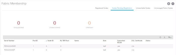
![]() For auto-discovery to occur by the APIC, the leaves will need to be running an ACI mode switch software release. For instructions on migrating from NX-OS, please refer to: https://www.cisco.com/c/en/us/td/docs/switches/datacenter/aci/apic/sw/kb/b_KB_Converting_N9KSwitch_NXOSStandaloneMode_to_ACIMode.html
For auto-discovery to occur by the APIC, the leaves will need to be running an ACI mode switch software release. For instructions on migrating from NX-OS, please refer to: https://www.cisco.com/c/en/us/td/docs/switches/datacenter/aci/apic/sw/kb/b_KB_Converting_N9KSwitch_NXOSStandaloneMode_to_ACIMode.html
4. Connect to the two Nexus 93180YC-FX leaf switches using serial consoles and login in as admin with no password (press enter). Use show inventory to get the leaf’s serial number.
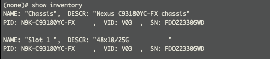
5. Match the serial numbers from the leaf listing to determine the A and B switches under Fabric Membership.
6. In the APIC GUI, within Nodes Pending Registration under Fabric Membership, right click the A leaf in the list and select Register.
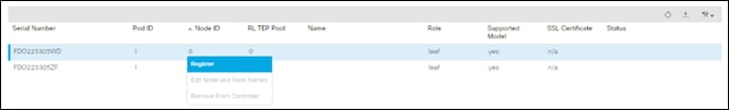
7. Enter a Node ID and a Node Name for the Leaf switch and click Register.
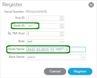
8. Repeat steps 4-7 for the B leaf in the list.
![]() During discovery, there may be some messages appearing about the leaves being inactive, these messages can be ignored.
During discovery, there may be some messages appearing about the leaves being inactive, these messages can be ignored.
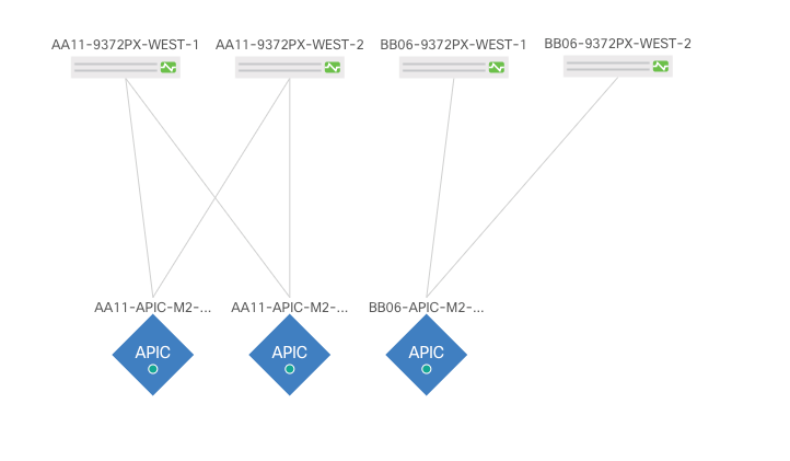
9. Click the Pod the leaves are associated with and select the Topology tab for the Pod. The discovered ACI Fabric topology will appear. It may take a few minutes for the new Nexus 93180YC-FX switches to appear and you will need to click Refresh for the complete topology to appear. You may also need to move the switches around to get the arrangement that you desire.
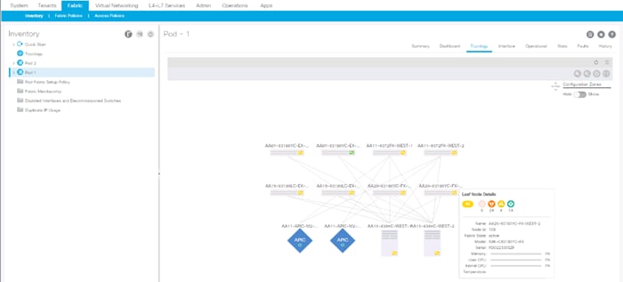
![]() The topology shown in the screenshot above is the topology of the validation lab fabric containing 8 leaf switches, 2 spine switches, and 2 APICs. The environment used is implementing an ACI Multi-Pod (not explained in this document), which places the third APIC in a remotely connected ACI Pod. Cisco recommends a cluster of at least 3 APICs in a production environment.
The topology shown in the screenshot above is the topology of the validation lab fabric containing 8 leaf switches, 2 spine switches, and 2 APICs. The environment used is implementing an ACI Multi-Pod (not explained in this document), which places the third APIC in a remotely connected ACI Pod. Cisco recommends a cluster of at least 3 APICs in a production environment.
Initial ACI Fabric Setup Verification
This section details the steps for the initial setup of the Cisco ACI Fabric, where the software release is validated, out of band management IPs are assigned to the new leaves, NTP setup is verified, and the fabric BGP route reflectors are verified.
Software Upgrade
To upgrade the software, follow these steps:
1. In the APIC GUI, select Admin -> Firmware.
2. This document was validated with ACI software release 4.1(2g). Select the Infrastructure tab within Firmware, and the Nodes sub-tab under Infrastructure. All switches should show the same firmware release and the release version should be at minimum n9000-14.1(2g). The switch software version should also correlate with the APIC version.
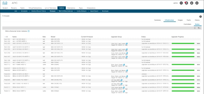
3. Click Admin > Firmware > Controller Firmware. If all APICs are not at the same release at a minimum of 4.1(2g), follow the Cisco APIC Management, Installation, Upgrade, and Downgrade Guide to upgrade both the APICs and switches if the APICs are not at a minimum release of 4.1(2g) and the switches are not at n9000-14.1(2g).
Set Up Out-of-Band Management IP Addresses for New Leaf Switches
To set up out-of-band management IP addresses, follow these steps:
1. To add Out-of-Band management interfaces for all the switches in the ACI Fabric, select Tenants -> mgmt.
2. Expand Tenant mgmt on the left. Right-click Node Management Addresses and select Create Static Node Management Addresses.
3. Enter the node number range for the new leaf switches (107-108 in this example).
4. Select the checkbox for Out-of-Band Addresses.
5. Select default for Out-of-Band Management EPG.
6. Considering that the IPs will be applied in a consecutive range of two IPs, enter a starting IP address and netmask in the Out-of-Band IPV4 Address field.
7. Enter the Out-of-Band management gateway address in the Gateway field.
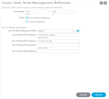
8. Click Submit, then click YES.
9. On the left, expand Node Management Addresses and select Static Node Management Addresses. Verify the mapping of IPs to switching nodes.
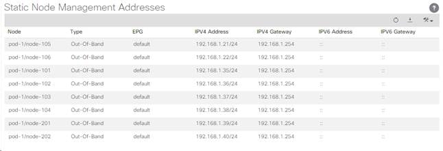
10. Direct out-of-band access to the switches is now available using SSH.
Verify Time Zone and NTP Server
This procedure will allow customers to verify setup of an NTP server for synchronizing the fabric time. To verify the time zone and NTP server set up, follow these steps:
1. To verify NTP setup in the fabric, select and expand Fabric -> Fabric Policies -> Policies -> Pod -> Date and Time.
2. Select default. In the Datetime Format - default pane, verify the correct Time Zone is selected and that Offset State is enabled. Adjust as necessary and click Submit and Submit Changes.
3. On the left, select Policy default. Verify that at least one NTP Server is listed.
4. If desired, select enabled for Server State to enable the ACI fabric switches as NTP servers. Click Submit.
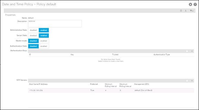
5. If necessary, on the right use the + sign to add NTP servers accessible on the out of band management subnet. Enter an IP address accessible on the out of band management subnet and select the default (Out-of-Band) Management EPG. Click Submit to add the NTP server. Repeat this process to add all NTP servers.
Verify Domain Name Servers
To verify optional DNS in the ACI fabric, follow these steps:
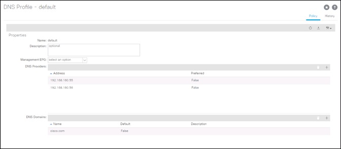
1. Select and expand Fabric > Fabric Policies > Policies > Global > DNS Profiles > default.
2. Verify the DNS Providers and DNS Domains.
3. If necessary, in the Management EPG drop-down, select the default (Out-of-Band) Management EPG. Use the + signs to the right of DNS Providers and DNS Domains to add DNS servers and the DNS domain name. Note that the DNS servers should be reachable from the out of band management subnet. Click SUBMIT to complete the DNS configuration.
Verify BGP Route Reflectors
In this ACI deployment, both of the spine switches are set up as BGP route-reflectors to distribute external routes throughout the fabric. To verify the BGP Route Reflector, follow these steps:
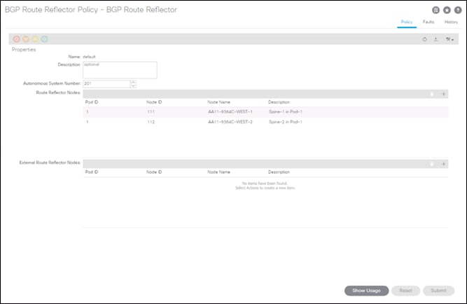
1. Select and expand System -> System Settings -> BGP Route Reflector.
2. Verify that a unique Autonomous System Number has been selected for this ACI fabric. If necessary, use the + sign on the right to add the two spines to the list of Route Reflector Nodes. Click Submit to complete configuring the BGP Route Reflector.
3. To verify the BGP Route Reflector has been enabled, select and expand Fabric -> Fabric Policies -> Pods -> Policy Groups. Under Policy Groups make sure a policy group has been created and select it. The BGP Route Reflector Policy field should show “default.”
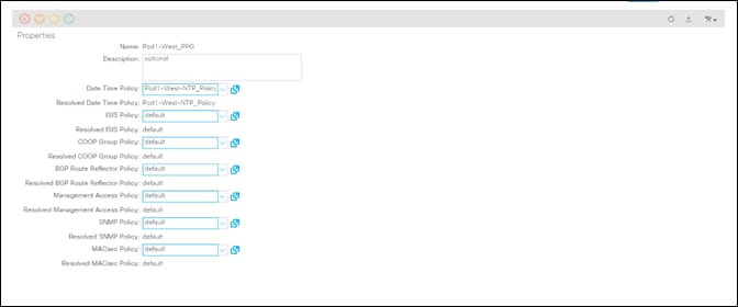
4. If a Policy Group has not been created, on the left, right-click Policy Groups under Pod Policies and select Create Pod Policy Group. In the Create Pod Policy Group window, provide an appropriate Policy Group name. Select the default BGP Route Reflector Policy. Click Submit to complete creating the Policy Group.
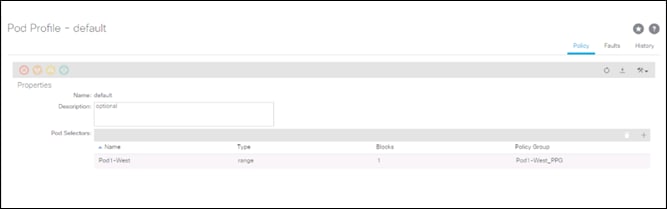
5. On the left expand Pods -> Profiles and select Pod Profile default.
6. Verify that the created Policy Group or the Fabric Policy Group identified above is selected. If the Fabric Policy Group is not selected, view the drop-down list to select it and click Submit.
Verify Fabric Wide Enforce Subnet Check for IP and MAC Learning
In this ACI deployment, Enforce Subnet Check for IP and MAC Learning should be enabled. To verify this setting, follow these steps:
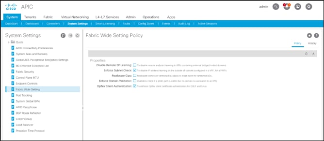
1. Select and expand System -> System Settings -> Fabric Wide Setting.
2. Ensure that Enforce Subnet Check is selected.
3. Select OpFlex Client Authentication.
![]() Required if you’re configuring Cisco AVE.
Required if you’re configuring Cisco AVE.
4. Click Submit.
Fabric Access Policy Setup
This section details the steps to create various access policies creating parameters for CDP, LLDP, LACP, etc. These policies are used during vPC and VMM domain creation. In an existing fabric, these policies may already exist.
The following policies will be setup during the Fabric Access Policy Setup:
| Access Interface Policies |
Purpose |
Policy Name |
| Link Level Policies |
Sets link to 40Gbps |
40Gbps-Link |
| Sets link to 25Gbps |
25Gbps-Link |
|
| Sets link to 10Gbps |
10Gbps-Link |
|
| Sets link to 1Gbps |
1Gbps-Link |
|
| CDP Interface Policies |
Enables CDP |
CDP-Enabled |
| Disables CDP |
CDP-Disabled |
|
| LLDP Interface Policies |
Enables LLDP |
LLDP-Enabled |
| Disables LLDP |
LLDP-Disabled |
|
| Port Channel Policies |
Sets LACP Mode |
LACP-Active |
| Sets MAC Pinning |
MAC-Pinning |
|
| Layer 2 Interface Policies |
Specifies VLAN Scope as Port Local |
VLAN-Scope-Local |
| Specifies VLAN Scope as Global |
VLAN-Scope-Global |
|
| Firewall Policies |
Disables Firewall |
Firewall-Disabled |
| Spanning Tree Policies |
Enables BPDU Filter and Guard |
BPDU-FG-Enabled |
| Disables BPDU Filter and Guard |
BPDU-FG-Disabled |
The existing policies can be used if configured the same way as listed. To define fabric access policies, follow these steps:
1. Log into the APIC AGUI.
2. In the APIC UI, select and expand Fabric -> Access Policies -> Policies -> Interface.
Create Link Level Policies
This procedure will create link level policies for setting up the 1Gbps, 10Gbps, and 40Gbps link speeds. To create the link level policies, follow these steps:
1. In the left pane, right-click Link Level and select Create Link Level Policy.
2. Name the policy as 1Gbps-Link and select the 1Gbps Speed.
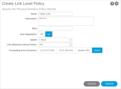
3. Click Submit to complete creating the policy.
4. In the left pane, right-click Link Level and select Create Link Level Policy.
5. Name the policy 10Gbps-Link and select the 10Gbps Speed.
6. Click Submit to complete creating the policy.
7. In the left pane, right-click Link Level and select Create Link Level Policy.
8. Name the policy 25Gbps-Link and select the 25Gbps Speed.
9. Click Submit to complete creating the policy.
10. In the left pane, right-click Link Level and select Create Link Level Policy.
11. Name the policy 40Gbps-Link and select the 40Gbps Speed.
12. Click Submit to complete creating the policy.
Create CDP Policy
This procedure creates policies to enable or disable CDP on a link. To create a CDP policy, follow these steps:
1. In the left pane, right-click CDP interface and select Create CDP Interface Policy.
2. Name the policy as CDP-Enabled and enable the Admin State.
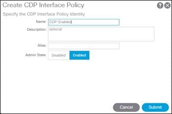
3. Click Submit to complete creating the policy.
4. In the left pane, right-click the CDP Interface and select Create CDP Interface Policy.
5. Name the policy CDP-Disabled and disable the Admin State.
6. Click Submit to complete creating the policy.
Create LLDP Interface Policies
This procedure will create policies to enable or disable LLDP on a link. To create an LLDP Interface policy, follow these steps:
1. In the left pane, right-click LLDP lnterface and select Create LLDP Interface Policy.
2. Name the policy as LLDP-Enabled and enable both Transmit State and Receive State.
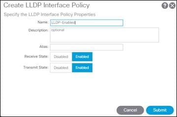
3. Click Submit to complete creating the policy.
4. In the left, right-click the LLDP lnterface and select Create LLDP Interface Policy.
5. Name the policy as LLDP-Disabled and disable both the Transmit State and Receive State.
6. Click Submit to complete creating the policy.
Create Port Channel Policy
This procedure will create policies to set LACP active mode configuration and the MAC-Pinning mode configuration. To create the Port Channel policy, follow these steps:
1. In the left pane, right-click Port Channel and select Create Port Channel Policy.
2. Name the policy as LACP-Active and select LACP Active for the Mode. Do not change any of the other values.
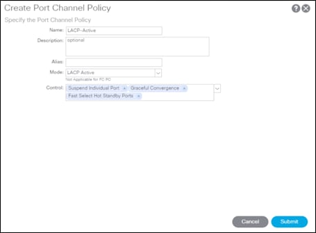
3. Click Submit to complete creating the policy.
4. In the left pane, right-click Port Channel and select Create Port Channel Policy.
5. Name the policy as MAC-Pinning and select MAC Pinning for the Mode. Do not change any of the other values.
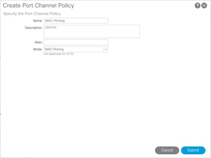
6. Click Submit to complete creating the policy.
Create BPDU Filter/Guard Policies
This procedure will create policies to enable or disable BPDU filter and guard. To create a BPDU filter/Guard policy, follow these steps:
1. In the left pane, right-click Spanning Tree Interface and select Create Spanning Tree Interface Policy.
2. Name the policy as BPDU-FG-Enabled and select both the BPDU filter and BPDU Guard Interface Controls.
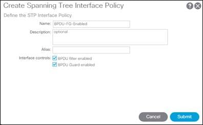
3. Click Submit to complete creating the policy.
4. In the left pane, right-click Spanning Tree Interface and select Create Spanning Tree Interface Policy.
5. Name the policy as BPDU-FG-Disabled and make sure both the BPDU filter and BPDU Guard Interface Controls are cleared.
6. Click Submit to complete creating the policy.
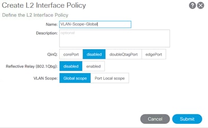
Create VLAN Scope Policy
To create policies to enable port local scope for all the VLANs, follow these steps:
1. In the left pane, right-click the L2 Interface and select Create L2 Interface Policy.
2. Name the policy as VLAN-Scope-Local and make sure Port Local scope is selected for VLAN Scope. Do not change any of the other values.
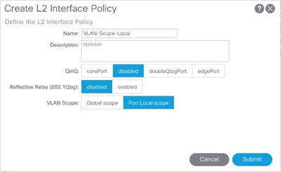
3. Click Submit to complete creating the policy.
4. Repeat steps 1-3 to create a VLAN-Scope-Global Policy and make sure Global scope is selected for VLAN Scope. Do not change any of the other values.
Create Firewall Policy
To create policies to disable a firewall, follow these steps:
1. In the left pane, right-click Firewall and select Create Firewall Policy.
2. Name the policy Firewall-Disabled and select Disabled for Mode. Do not change any of the other values.
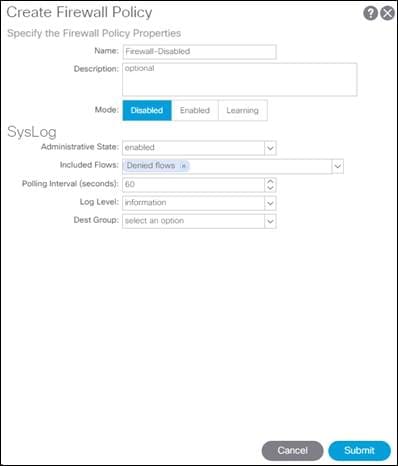
3. Click Submit to complete creating the policy.
Create Virtual Port Channels (vPCs)
This section details the steps to setup vPCs for connectivity to the In-Band Management Network and Cisco UCS.
vPC - Management Switch
To setup a vPC for connectivity to the existing In-Band Management Network, follow these steps:
![]() This deployment guide covers the configuration for a single, pre-existing Cisco Nexus management switch. You can adjust the management configuration depending on your connectivity setup. The In-Band Management Network provides connectivity of Management Virtual Machines and Hosts in the ACI fabric to existing services on the In-Band Management network outside of the ACI fabric. Layer 3 connectivity outside of the ACI Fabric is assumed between the In-Band and Out-of-Band Management networks. This setup creates management networks that are physically isolated from tenant networks. In this validation, a 1GE vPC from two 1GE capable leaf switches in the fabric is connected to a port-channel on a Nexus 5K switch outside the fabric. Multiple upstream management switches are supported, but only one is used in this example.
This deployment guide covers the configuration for a single, pre-existing Cisco Nexus management switch. You can adjust the management configuration depending on your connectivity setup. The In-Band Management Network provides connectivity of Management Virtual Machines and Hosts in the ACI fabric to existing services on the In-Band Management network outside of the ACI fabric. Layer 3 connectivity outside of the ACI Fabric is assumed between the In-Band and Out-of-Band Management networks. This setup creates management networks that are physically isolated from tenant networks. In this validation, a 1GE vPC from two 1GE capable leaf switches in the fabric is connected to a port-channel on a Nexus 5K switch outside the fabric. Multiple upstream management switches are supported, but only one is used in this example.
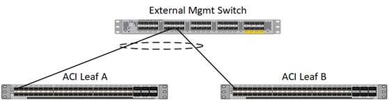
Table 11 VLAN for Incoming IB-MGMT
| Name |
VLAN |
| Site1-IB-MGMT |
<119> |
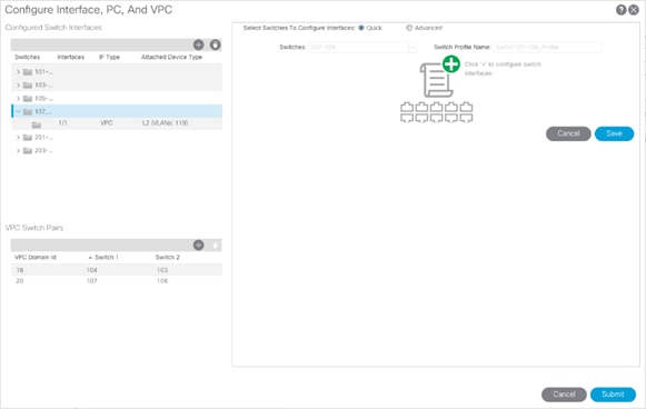
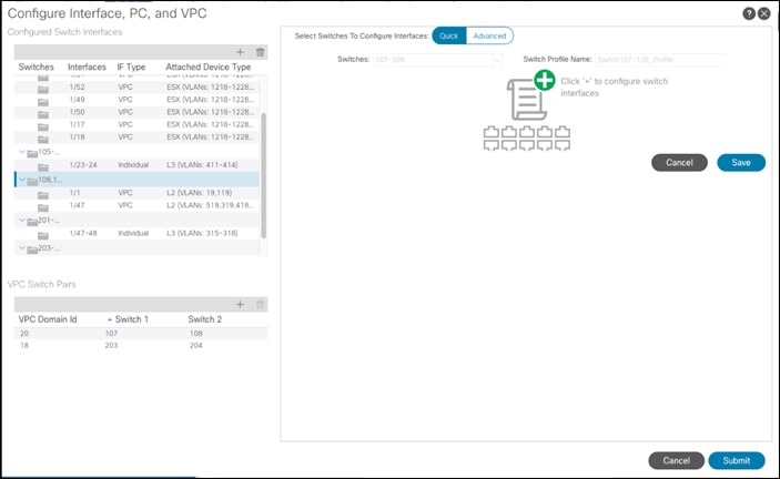
4. In the APIC GUI, at the top select Fabric -> Access Policies -> Quick Start.
5. In the right pane select Configure an interface, PC and VPC.
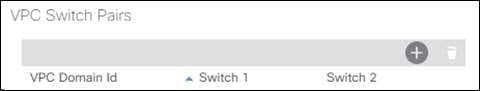
6. In the configuration window, configure a VPC domain between the leaf switches by clicking “+” under VPC Switch Pairs. If a VPC Domain already exists between the two switches being used for this vPC, skip to step 7.
7. Enter a VPC Domain ID (20 in this example).
8. From the drop-down list, select Switch A and Switch B IDs to select the two leaf switches.
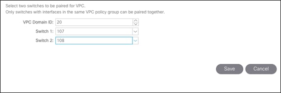
9. Click Save.
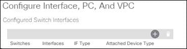
10. If a profile for the two leaf switches being used does not already exist under Configured Switch Interfaces, click the “+” under Configured Switch Interfaces. If the profile does exist, select it and proceed to step 10.
11. From the Switches drop-down list on the right, select both the leaf switches being used for this vPC.
12. Leave the system generated Switch Profile Name in place.
13. Click the big green “+” on the right to configure switch interfaces.
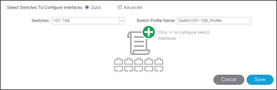
14. Configure various fields as shown in the figure below. In this screen shot, port 1/1 on both leaf switches is connected to a Nexus switch using 1Gbps links.
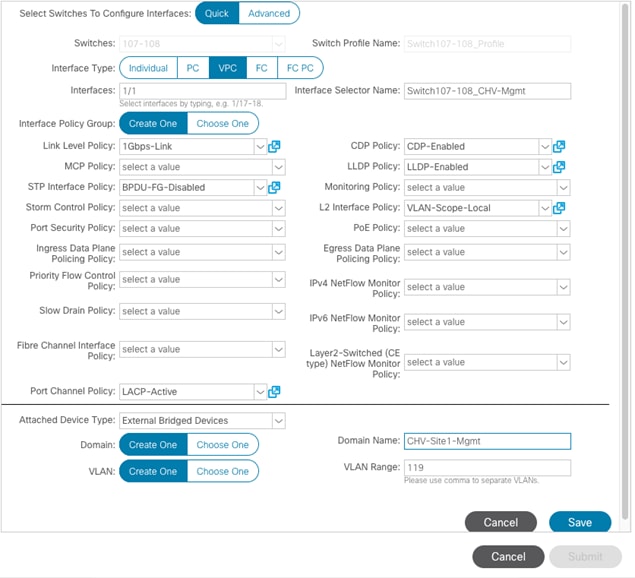
15. Click Save.
16. Click Save again to finish the configuring switch interfaces.
17. Click Submit.
![]() To validate the configuration, log into the Nexus switch (IP listed under Fabric -> Inventory -> [pod] -> [leaf] -> Management Interfaces) and verify the port-channel is up (show port-channel summary).
To validate the configuration, log into the Nexus switch (IP listed under Fabric -> Inventory -> [pod] -> [leaf] -> Management Interfaces) and verify the port-channel is up (show port-channel summary).
vPC – Cisco UCS Fabric Interconnects
To setup vPCs for connectivity to the Cisco UCS Fabric Interconnects, follow these steps:
Figure 3 VLANs Configured for Cisco UCS
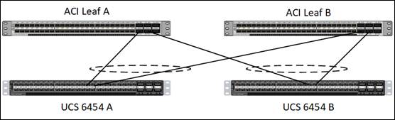
Table 12 VLANs for Cisco UCS Hosts
| Name |
VLAN |
| Native |
<2> |
| Site1-Infra |
<119> |
| Common |
<319> |
| Internal-Infra |
<419> |
| vMotion |
<519> |
1. In the APIC GUI, select Fabric -> Access Policies -> Quick Start.
2. In the right pane, select Configure and interface, PC and VPC.
3. In the configuration window, select the Configured Switch Interfaces line for the two 93180YC-FX switches.
4. Click ![]() to add switch interfaces.
to add switch interfaces.
5. Configure various fields as shown in the figure below. In this screenshot, port 1/47 on both leaf switches is connected to UCS Fabric Interconnect A using 25Gbps links.
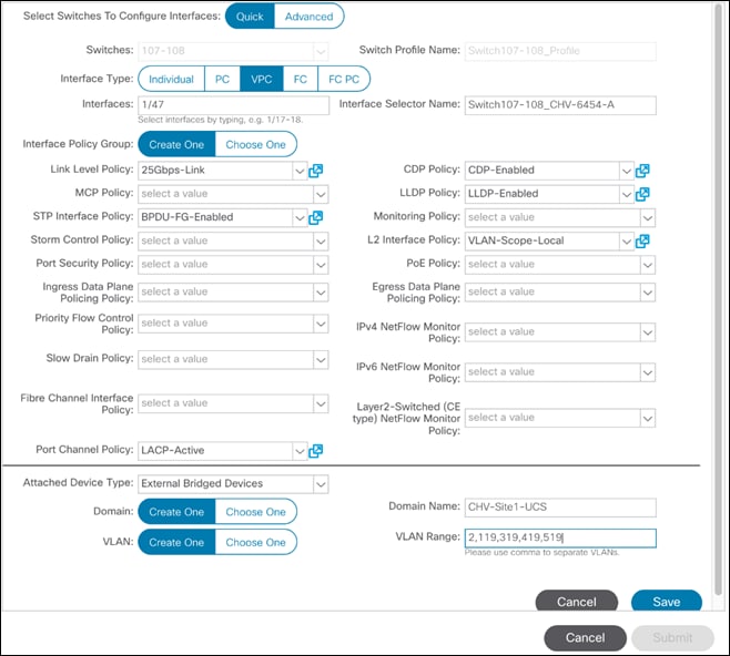
6. Click Save.
7. Click Save again to finish the configuring switch interfaces.
8. Click Submit.
9. From the right pane, select Configure and interface, PC and VPC.
10. Select the switches configured in the last step under Configured Switch Interfaces.
11. Click ![]() on the right to add switch interfaces.
on the right to add switch interfaces.
12. Configure various fields as shown in the screenshot. In this screenshot, port 1/48 on both leaf switches is connected to the Cisco UCS Fabric Interconnect B using 25Gbps links. Instead of creating a new domain, the External Bridged Device created in the last step (CH-Site1-UCS) is attached to the FI-B as shown below.
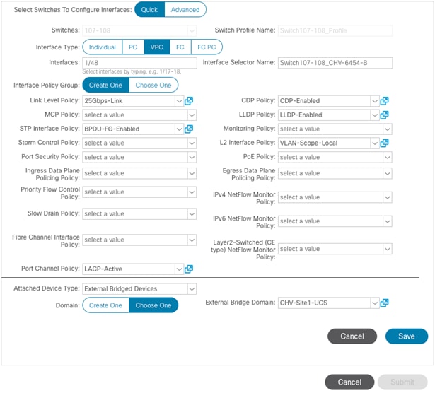
13. Click Save.
14. Click Save again to finish the configuring switch interfaces.
15. Click Submit.
16. Optional: Repeat this procedure to configure any additional UCS domains. For a uniform configuration, the External Bridge Domain (UCS) will be utilized for all the Fabric Interconnects.
Deploy Shared Layer 3 Connectivity to Outside Networks – Pod-1
Follow the procedures outlined in this section to establish Layer 3 connectivity or a Shared L3Out from the ACI fabric to networks outside the ACI fabric.
Deployment Overview
In this design, the Shared L3Out connection is established in the system-defined common Tenant so that it can be used by all tenants in the ACI fabric. Tenants must not use overlapping addresses when connecting to the outside networks using the same shared L3Out connection. The connection uses four 10GbE interfaces between border leaf switches deployed earlier and pair of Nexus 7000 switches. The Nexus 7000 routers serve as the external gateway to the networks outside the fabric. OSPF is utilized as the routing protocol to exchange routes between the two networks. Some highlights of this connectivity are:
· Pair of Nexus 7000 routers are connected to a pair of Nexus ACI leaf switches – using a total of 4 links.
· VLANs are used for connectivity across the 4 links – using a total of 4 VLANs. VLANs are configured on separate sub-interfaces.
· Fabric Access Policies are configured on ACI Leaf switches to connect to the External Routed domain (via Nexus 7000s) using VLAN pool (vlans: 311-314).
· A dedicated VRF common-SharedL3Out_VRF is configured in Tenant common for external connectivity.
· The shared Layer 3 Out created in common Tenant “provides” an external connectivity contract that can be “consumed” from any tenant.
· The Nexus 7000s are configured to originate and send a default route to the Nexus 9000 leaf switches using OSPF.
· ACI leaf switches advertise tenant subnets back to Nexus 7000 switches.
· In ACI 4.0, ACI leaf switches can also advertise host-routes if it is enabled.
Create VLAN Pool for External Routed Domain
In this section, a VLAN pool is created to enable connectivity to the external networks, outside the ACI fabric. The VLANs in the pool are for the four links that connect ACI Border Leaf switches to the Nexus Gateway routers in the non-ACI portion of the customer’s network.
Setup Information
Table 13 VLAN Pool for Shared L3Out in Pod-1
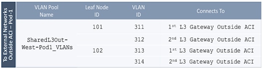
![]() Configuration references are included for Pod1 to align with an eventual Multi-Pod buildout involving two pods.
Configuration references are included for Pod1 to align with an eventual Multi-Pod buildout involving two pods.
Deployment Steps
To configure a VLAN pool to connect to external gateway routers outside the ACI fabric, follow these steps:
1. Use a browser to navigate to the APIC GUI. Log in using the admin account.
2. From the top navigation menu, select Fabric > Access Policies.
3. From the left navigation pane, expand and select Pools > VLAN.
4. Right-click and select Create VLAN Pool.
5. In the Create VLAN Pool pop-up window, specify a Name and for Allocation Mode, select Static Allocation.
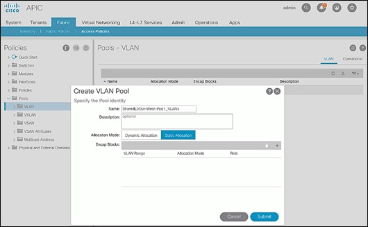
6. For Encap Blocks, use the [+] button on the right to add VLANs to the VLAN Pool. In the Create Ranges pop-up window, configure the VLANs that need to be configured from the Border Leaf switches to the external gateways outside the ACI fabric. Leave the remaining parameters as is.
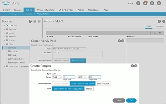
7. Click OK. Use the same VLAN ranges on the external gateway routers to connect to the ACI Fabric.
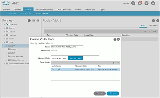
8. Click Submit to complete.
Configure Domain Type for External Routed Domain
To configure the domain type for the external domain, follow the procedures outlined in this section.
Deployment Steps
To specify the domain type for connecting to external gateway routers outside the ACI fabric, follow these steps:
1. Use a browser to navigate to the APIC GUI. Log in using the admin account.
2. From the top navigation menu, select Fabric > Access Policies.
3. From the left navigation pane, expand and select Physical and External Domains > External Routed Domains.
4. Right-click External Routed Domains and select Create Layer 3 Domain.
5. In the Create Layer 3 Domain pop-up window, specify a Name for the domain. For the VLAN Pool, select the previously created VLAN Pool from the drop-down list.
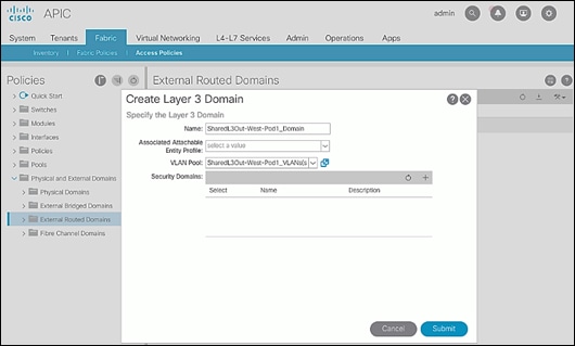
6. Click Submit to complete.
Create AAEP for External Routed Domain
To configure Attachable Access Entity Profile (AAEP) for external domain, follow the procedures outlined in this section.
Setup Information
Table 14 Attachable Access Entity Profile (AAEP) for Shared L3Out in Pod-1
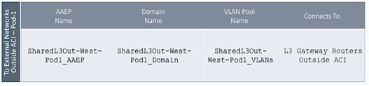
Deployment Steps
To create an Attachable Access Entity Profile (AAEP) to connect to external gateway routers outside the ACI fabric, follow these steps:
1. Use a browser to navigate to the APIC GUI. Log in using the admin account.
2. From the top navigation menu, select Fabric > Access Policies.
3. From the left navigation pane, expand and select Policies > Global > Attachable Access Entity Profiles.
4. Right-click and select Create Attachable Access Entity Profile.
5. In the Create Attachable Access Entity Profile pop-up window, specify a Name.
6. For the Domains, click the [+] on the right-side of the window and select the previously created domain from the drop-down list below Domain Profile.
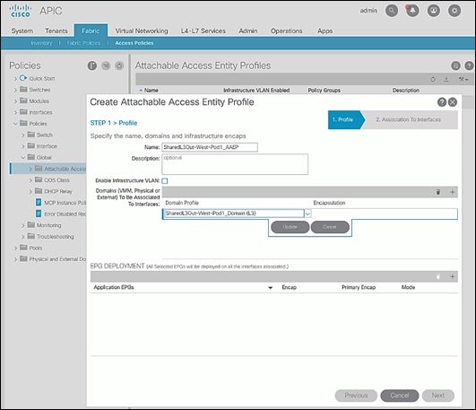
7. Click Update.
8. You should now see the selected domain and the associated VLAN Pool as shown below.
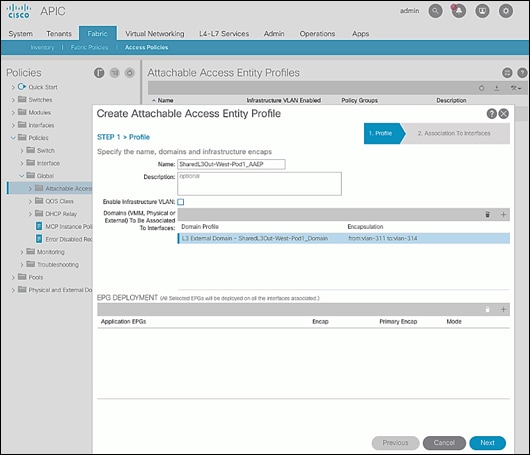
9. Click Next. This profile is not associated with any interfaces at this time – they can be associated once the interfaces are configured in the upcoming section.
10. Click Finish to complete.
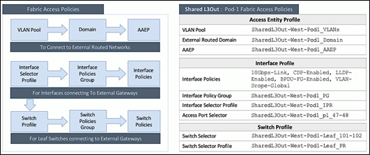
Configure Interfaces to External Routed Domain
To configure interfaces to the external routed domain, follow the procedures outlined in this section.
Setup Information
· Border Leaf switches (Node ID: 101,102) in Pod-1 connect to External Gateways (Nexus 7000 series switches) using 10Gbps links, on ports 1/47 and 1/48.
Figure 4 Fabric Access Policies for Shared L3Out in Pod-1
Create Interface Policy Group for Interfaces to External Routed Domain
To create an interface policy group to connect to external gateway routers outside the ACI fabric, follow these steps:
1. Use a browser to navigate to the APIC GUI. Log in using the admin account.
2. From the top navigation menu, select Fabric > Access Policies.
3. From the left navigation pane, expand and select Interfaces > Leaf Interfaces > Policy Groups > Leaf Access Port.
4. Right-click and select Create Leaf Access Port Policy Group.
5. In the Create Leaf Access Port Policy Group pop-up window, specify a Name and select the applicable interface policies from the drop-down list for each field.
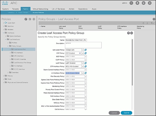
6. For the Attached Entity Profile, select the previously created AAEP to external routed domain.
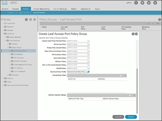
7. Click Submit to complete.
Create Interface Profile for Interfaces to External Routed Domain
To create an interface profile to connect to external gateway routers outside the ACI fabric, follow these steps:
1. Use a browser to navigate to the APIC GUI. Log in using the admin account.
2. From the top navigation menu, select Fabric > Access Policies.
3. From the left navigation menu, expand and select Interfaces > Leaf Interfaces > Profiles.
4. Right-click and select Create Leaf Interface Profile.
5. In the Create Leaf Interface Profile pop-up window, specify a Name. For Interface Selectors, click the [+] to select access ports to apply interface policies to. In this case, the interfaces are access ports that connect Border Leaf switches to gateways outside ACI.
6. In the Create Access Port Selector pop-up window, specify a selector Name. For the Interface IDs, specify the access ports connecting to the two external gateways. For the Interface Policy Group, select the previously created Policy Group from the drop-down list.
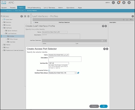
7. Click OK to close the Create Access Port Selector pop-up window.
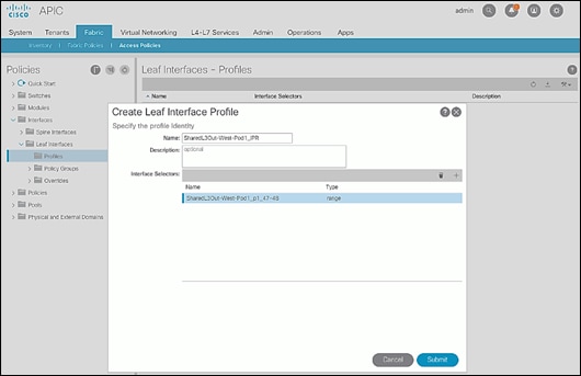
8. Click Submit to complete.
Create Leaf Switch Profile to External Routed Domain
To create leaf switch profile to connect to external gateway routers outside the ACI fabric, follow these steps:
1. Use a browser to navigate to the APIC GUI. Log in using the admin account.
2. From the top navigation menu, select Fabric > Access Policies.
3. From the left navigation menu, expand and select Switches > Leaf Switches > Profiles.
4. Right-click and select Create Leaf Profile.
5. In the Create Leaf Profile pop-up window, specify a profile Name. For Leaf Selectors, click the [+] to select the Leaf switches to apply the policies to. In this case, the Leaf switches are the Border Leaf switches that connect to the gateways outside ACI.
6. Specify a Leaf Selector Name. For the Interface IDs, specify the access ports connecting to the two external gateways. For Blocks, select the Node IDs of the Border Leaf switches from the drop-down list.
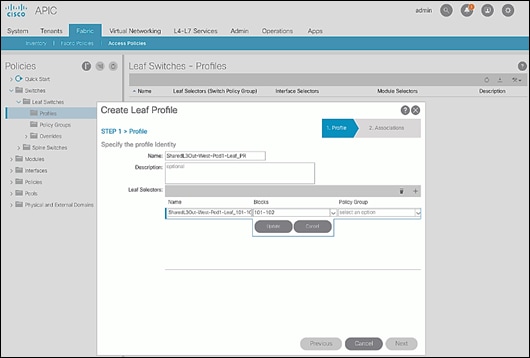
7. Click Update.
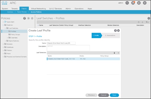
8. Click Next.
9. In the Associations window, select the previously created Interface Selector Profiles from the list.
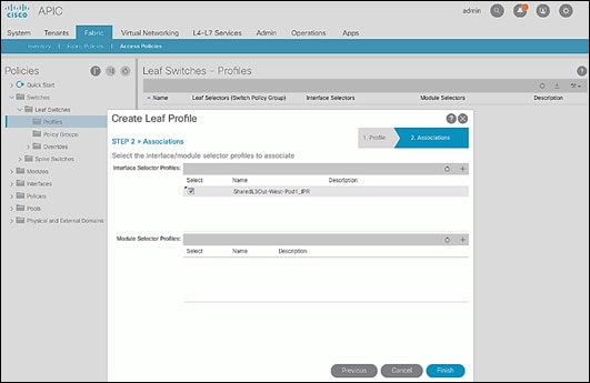
10. Click Finish to complete.
Configure Tenant Networking for Shared L3Out
To configure tenant networking to connect to networks outside the ACI fabric, follow the procedures outlined in this section.
Setup Information
Figure 5 Tenant Networking for Shared L3Out
Deployment Steps
To configure tenant networking for the Shared L3Out for connectivity outside the ACI fabric, follow these steps:
1. Use a browser to navigate to the APIC GUI. Log in using the admin account.
2. From the top navigation menu, select Tenants > common.
3. From the left navigation pane, select and expand Tenant common > Networking > VRFs.
4. Right-click and select Create VRF.
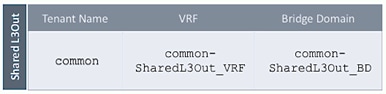
5. In the Create VRF pop-up window, STEP 1 > VRF, specify a Name (for example, common-SharedL3Out_VRF).
6. Deselect the check box for Create a Bridge Domain.
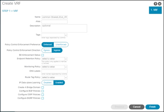
7. Click Finish.
Configure External Routed Networks under Tenant Common
To configure external routed networks under Tenant Common, follow the procedures outlined in this section.
Setup Information
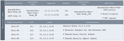
Table 15 Routed Outside – Pod-1
Deployment Steps
To configure the external routed networks under Tenant common, follow these steps:
1. Use a browser to navigate to the APIC GUI. Log in using the admin account.
2. From the top navigation menu, select Tenants > common.
3. In the left navigation pane, select and expand Tenant common > Networking > External Routed Networks.
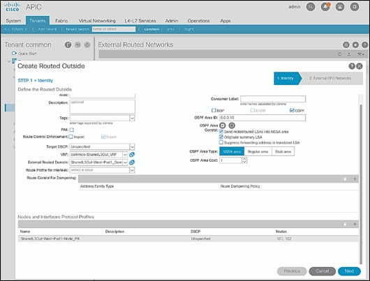
4. Right-click and select Create Routed Outside.
5. In the Create Routed Outside pop-up window, specify a Name.
6. Select the check box next to OSPF.
7. For the OSPF Area ID, enter 0.0.0.10 (should match the external gateway configuration).
8. For the VRF, select the previously created VRF from the drop-down list.
9. For the External Routed Domain, select the previously created domain from the drop-down list.
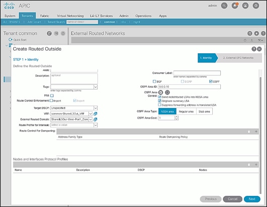
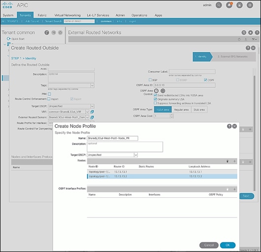
10. For Nodes and Interfaces Protocol Profiles, click [+] to add a Node Profile.
11. In the Create Node Profile pop-up window, specify a profile Name.
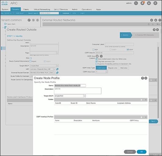
12. For Nodes, click [+] to add a Node.
13. In the Select Node pop-up window, for the Node ID, select first Border Leaf switch from the drop-down list. For the Router ID, specify the router ID for the first Border Leaf Switch (for example, 13.13.13.1).
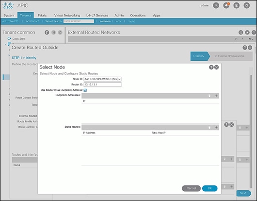
14. Click OK to complete selecting the Node.
15. Repeat steps 1-14 to add the second Border Leaf to the list of Nodes.
16. For OSPF Interface Profiles, click [+] to add a profile.
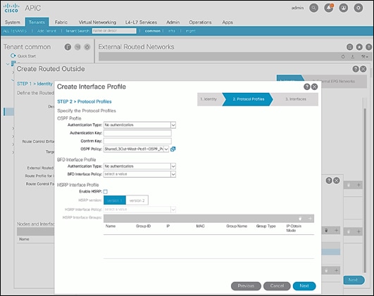
17. In the Create Interface Profile pop-up window, for Step 1 > Identity, specify a Name.
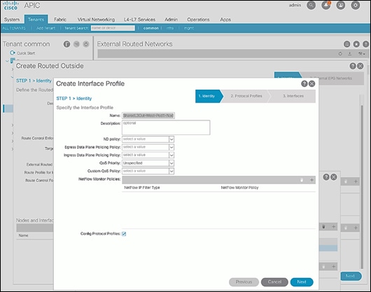
18. Click Next.
19. In Step 2 > Protocol Profiles, for the OSPF Policy, use the drop-down list to select Create OSPF Interface Policy.
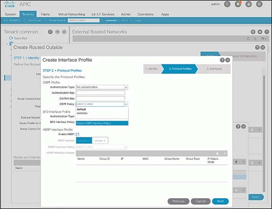
20. In the Create OSPF Interface Policy pop-up window, specify a Name. For Network Type, select Point-to-Point. For Interface Controls, select the checkbox for MTU ignore.
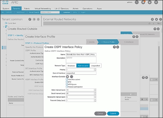
21. Click Submit to complete creating the OSPF policy.
22. In the Create Interface Profile pop-up window, click Next.
23. For STEP 3 > Interfaces, select the tab for Routed Sub-Interface. Click [+] on the right side of the window to add a routed sub-interface.
24. In the Select Routed Sub-Interface pop-up window, for Node, select the first Border Leaf. For Path, select the interface (for example, 1/47) on the first Border Leaf that connects to the first external gateway. For Encap, specify the VLAN (for example, 311). For IPv4 Primary / IPv6 Preferred Address, specify the address (for example, 10.113.1.1/30).
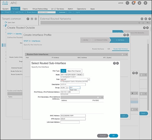
25. Click OK to complete configuring the first routed sub-interface.
26. Repeat steps 1-25 to create the next sub-interface that connects the first Leaf to the second Gateway.
27. Repeat steps 1-25 to create the sub-interfaces on the second Leaf that connects to the two gateways.
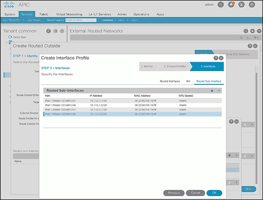
28. Click OK to complete creating the Interface Profile.
29. In the Create Routed Outside pop-up window, click Next.
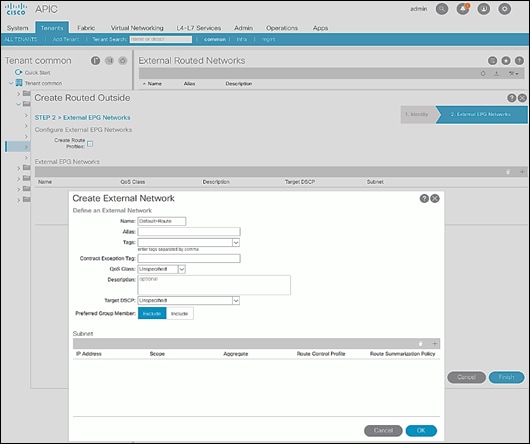
30. In STEP 2 > External EPG Networks, for External EPG Networks, click [+] to add an external network.
31. In the Created External Network pop-up window, specify a Name (for example, Default-Route).
32. For Subnet, click [+] to add a Subnet.
33. In the Create Subnet pop-up window, for the IP Address, enter a route (for example, 0.0.0.0/0). Select the checkboxes for External Subnets for the External EPG, Shared Route Control Subnet, and Shared Security Import Subnet.
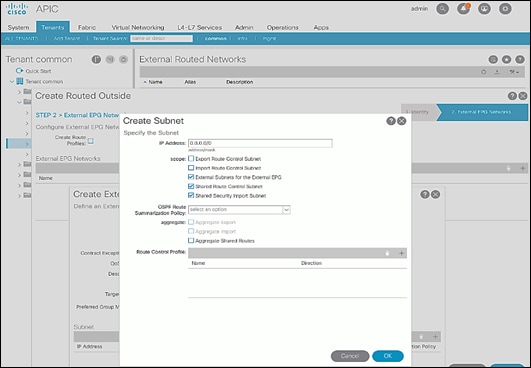
34. Click OK to complete creating the subnet.
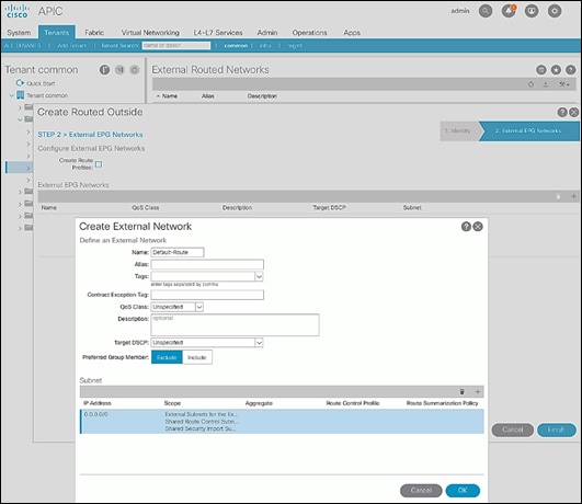
35. Click OK again to complete creating the external network.
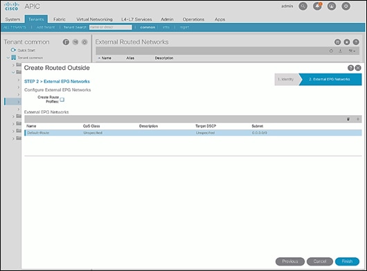
36. Click Finish to complete creating the Routed Outside.
Create Contracts for External Routed Networks from Tenant (common)
To create contracts to access external routed networks, follow the procedures outlined in this section.
Setup Information
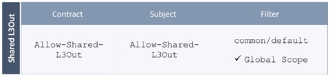
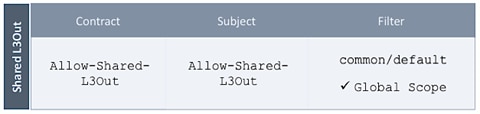
Table 16 Contract Created
Deployment Steps
To create contracts for external routed networks from Tenant common, follow these steps:
1. Use a browser to navigate to the APIC GUI. Log in using the admin account.
2. From the top navigation menu, select Tenants > common.
3. In the left navigation pane, select and expand Tenant common > Contracts.
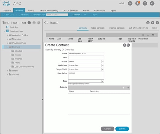
4. Right-click Contracts and select Create Contract.
5. In the Create Contract pop-up window, specify a Name.
6. For Scope, select Global from the drop-down list to allow the contract to be consumed by all tenants.
7. For Subjects, click [+] on the right side to add a contract subject.
8. In the Create Contract Subject pop-up window, specify a Name.
9. For Filters, click [+] on the right side to add a filter.
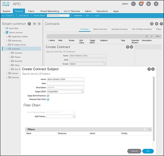
10. In the Filters section of the window, for Name, select default (common) from the drop-down list to create a default filter for Tenant common.
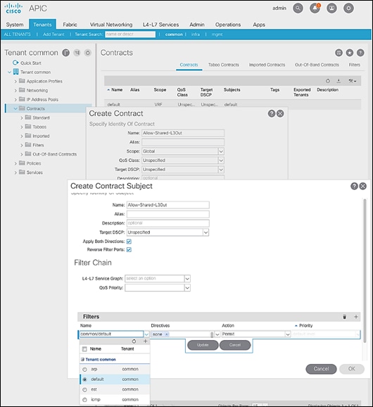
11. Click Update.
12. Click OK to complete creating the contract subject.
13. Click Submit to complete creating the contract.
Provide Contracts for External Routed Networks from Tenant (common)
To provide contracts to access external routed networks, follow the procedures outlined in this section.
Setup Information
Table 17 External Routed Network Contracts
Deployment Steps
To provide contracts for external routed networks from Tenant common, follow these steps:
1. Use a browser to navigate to the APIC GUI. Log in using the admin account.
2. From the top navigation menu, select Tenants > common.
3. In the left navigation pane, select and expand Tenant common > Networking > External Routed Networks.
4. Select and expand the recently created External Routed Network for SharedL3out or Routed Outside network (for example, SharedL3Out-West-Pod1_RO).
5. Select and expand Networks.
6. Select the recently created route (for example, Default-Route).
7. In the right window pane, select the tab for Policy and then Contracts.
8. Under the Provided Contracts tab, click [+] on the right to add a Provided Contract.
9. For Name, select the previously created contract (for example, common/Allow-Shared-L3Out) from the drop-down list.
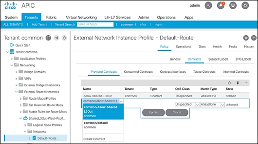
10. Click Update.
11. Other Tenants can now ‘consume’ the Allow-Shared-L3Out contract to route traffic outside the ACI fabric. This deployment example shows a default filter to allow all traffic. More restrictive contracts can be created for a more restrictive access to destinations outside the fabric.
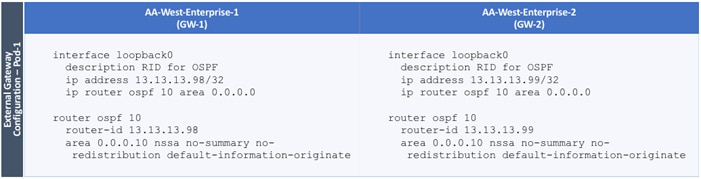
Configure External Gateways in the Outside Network
This section provides a sample configuration from the external Layer 3 Gateways routers that connect to the fabric. The gateways are in the external network and peer using OSPF to two ACI border leaf switches in the fabric. Nexus 7000 routers are used as External gateway routers in this design, but other Cisco models can also be used.
![]() The gateway configuration shown below shows only the relevant portion of the configuration; it is not the complete configuration.
The gateway configuration shown below shows only the relevant portion of the configuration; it is not the complete configuration.
Enable Protocols
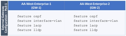
The protocols used between the ACI border leaf switches and external gateways have to be explicitly enabled on Nexus platforms used as external gateways in this design. The configuration to enable these protocols are provided below.
Table 18 Protocols Enabled
Configure OSPF
OSPF is used between the external gateways and ACI border leaf switches to exchange routing between the two domains. The global configuration for OSPF is provided below. Loopback is used as the router IDs for OSPF. Note that interfaces between ACI border leaf switches will be in OSPF Area 10.
Table 19 External Gateways for Pod-2 – Protocols
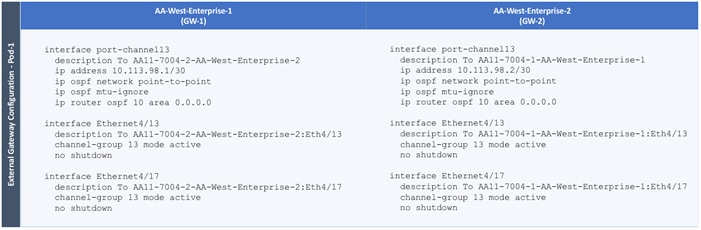
Configure Interfaces
The interface level configuration for connectivity between external gateways and ACI border leaf switches in Pod-1 is provided below. Note that interfaces to ACI are in OSPF Area 10 while the loopbacks and port-channels between the gateways are in OSPF Area 0.
Table 20 Interface Configuration – To ACI Border Leaf Switches

The configuration on the port-channel with 2x10GbE links that provide direct connectivity between the external gateways is provided below.
Table 21 Interface Configuration – Between External Gateways
Deploy CHV-Foundation Tenant
This section details the steps for creating the CHV-Foundation Tenant in the ACI Fabric. This tenant will host infrastructure connectivity for Internal Infrastructure (VMware ESXi on UCS nodes, Hitachi VSP) as well as Shared Infrastructure (AD/DNS). To deploy the CHV-Foundation Tenant, follow these steps:
1. In the APIC GUI, select Tenants -> Add Tenant.
2. Name the Tenant CHV-Foundation.
3. For the VRF Name, enter CHV-Foundation. Keep the check box “Take me to this tenant when I click finish” checked.
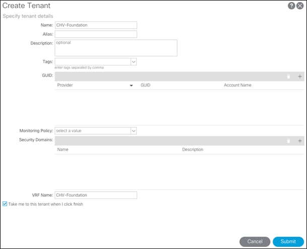
4. Click Submit to finish creating the Tenant.
Create Bridge Domains
The following Bridge Domains and EPGs will be created to be associated with the EPGs:
| Bridge Domain |
EPG |
VLAN |
Subnet(gw/mask) |
| BD-CHV-Foundation-Internal |
Site-Infra |
119 |
10.1.168.254/24 |
| BD-CHV-Common |
Common |
319 |
10.168.168.254/24 |
| BD-ESXi |
Host-Mgmt |
419 |
10.4.168.254/24 |
| BD-vMotion |
vMotion |
519 |
|
To create a Bridge Domain, follow these steps:
1. In the left pane, expand Tenant CHV-Foundation and Networking.
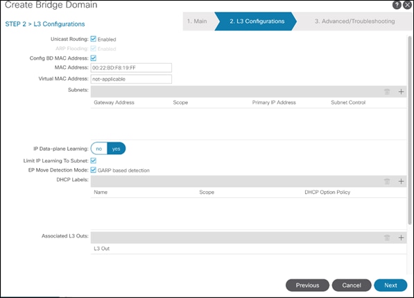
2. Right-click Bridge Domains and select Create Bridge Domain.
3. Name the Bridge Domain BD-CHV-Foundation-Internal.
4. Select CHV-Foundation from the VRF drop-down list.
5. Select Custom under Forwarding and enable Flood for L2 Unknown Unicast.
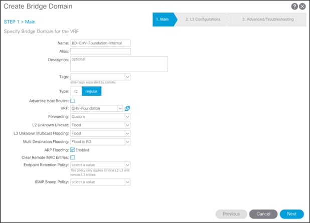
6. Click Next.
7. Under L3 Configurations, make sure Limit IP Learning to Subnet is selected and select EP Move Detection Mode – GARP based detection.
8. Select the + option to the far right of Subnets.
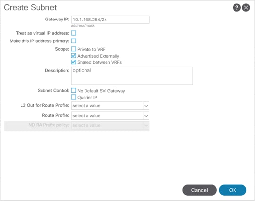
9. Provide the appropriate Gateway IP and mask for the subnet.
10. Select the Scope options for Advertised Externally and Shared between VRFs.
11. Click OK.
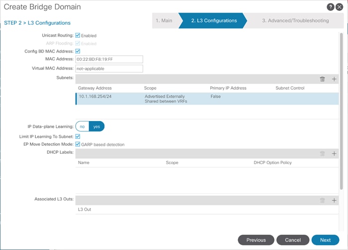
12. Select Next.
13. No changes are needed for Advanced/Troubleshooting. Click Finish to finish creating the Bridge Domain.
14. Repeat these steps for the [BD-CHV-Common, BD-ESXi, and BD-vMotion] bridge domain creations, leaving out the Subnet creation for the BD-vMotion bridge domain.
Create Application Profile for Infrastructure
Infrastructure will reside within the Foundation tenant to provide shared services like AD/DNS but will also contain internal the infrastructure backend like UCSM, vCenter, and Hitachi VSP. To create an application profile for Infra, follow these steps:
1. In the left pane, expand tenant CHV-Foundation, right-click Application Profiles and select Create Application Profile.
2. Name the Application Profile Infra and click Submit to complete adding the Application Profile.
Create EPG for Shared Infra Access
This EPG will be common resources used by the infrastructure as well as the applications within the tenant, such as vCenter and AD/DNS.
To create the EPG for Shared-Infra access, follow these steps:
1. In the left pane, expand the Application Profiles and right-click the Infra Application Profile and select Create Application EPG.
2. Name the EPG Common.
3. From the Bridge Domain drop-down list, select Bridge Domain BD-CHV-Common.

4. Click Finish to complete creating the EPG.
5. In the left menu, expand the newly created EPG, right-click Domains and select Add L2 External Domain Association.
6. Select the CHV-Site1-UCS L2 External Domain Profile.

7. Click Submit.
8. In the left menu, right-click Static Ports and select Deploy Static EPG on PC, VPC, or Interface.
9. Select the Virtual Port Channel Path Type, then for Path select the vPC for the first UCS Fabric Interconnect.
10. For Port Encap leave VLAN selected and fill in the UCS Common VLAN ID <319>.

11. Set the Deployment Immediacy to Immediate and click Submit.
12. Repeat steps 9-11 to add the Static Port mapping for the second UCS Fabric Interconnect vPC.
13. In the left navigation pane for the Common EPG, right click Contracts, and select add Consumed Contract.
14. In the Add Consumed Contract pop-up window, select the Allow-Shared-L3Out contract from the drop-down list.
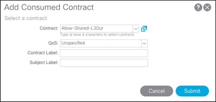
15. Click Submit.
Create EPG for Internal Infra Access
This EPG is an example of backend infrastructure that doesn’t need to be exposed to the application tenant, containing components such as Cisco UCSM and the Hitachi VSP.
To create the EPG for Internal-Infra access, follow these steps:
1. In the left pane, expand the Application Profiles and right-click the Infra Application Profile and select Create Application EPG.
2. Name the EPG Internal-Infra.
3. From the Bridge Domain drop-down list, select Bridge Domain BD-CHV-Foundation-Internal.
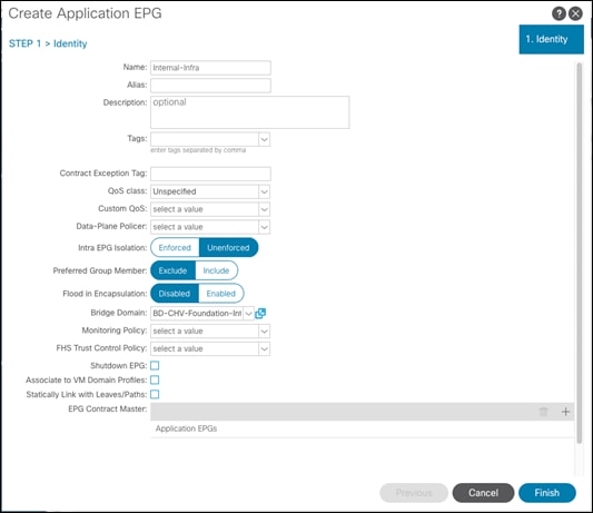
4. Click Finish to complete creating the EPG.
5. In the left menu, expand the newly created EPG, right-click Domains and select Add L2 External Domain Association.
6. Select the CHV-Site1-UCS L2 External Domain Profile.

7. Click Submit.
8. Repeat steps 5-7 for the CHV-Site1-Mgmt L2 external domain.
9. In the left menu, right-click Static Ports and select Deploy Static EPG on PC, VPC, or Interface.
10. Select the Virtual Port Channel Path Type, then for Path select the vPC for the first UCS Fabric Interconnect.
11. For Port Encap leave VLAN selected and fill in the UCS Site-Infra VLAN ID <119>.

12. Set the Deployment Immediacy to Immediate and click Submit.
13. Repeat steps 9-12 to add the Static Port mapping for the second UCS Fabric Interconnect, and the upstream management vPC.
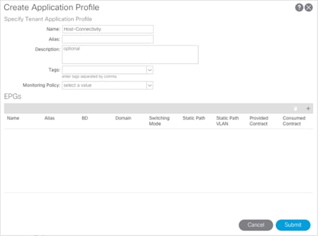
Create Application Profile for Host Connectivity
The Foundation tenant will also contain EPGs for hypervisor specific traffic that will be grouped into their own Application Profile. These EPGs are for the ESXi management VMkernel which will be connected via a contract to the vCenter, and a vMotion EPG which will hold the non-routed vMotion traffic between the ESXi hosts.
To create an application profile for Host-Connectivity, follow these steps:
1. In the left pane, expand tenant CHV-Foundation, right-click Application Profiles and select Create Application Profile.
2. Name the Application Profile Host-Connectivity and click Submit to complete adding the Application Profile.
Create EPG for Host Management
This EPG will be for the management communication between ESXi hosts and vCenter.
To create the EPG for Host-Mgmt access, follow these steps:
1. In the left pane, expand the Application Profiles and right-click the Infra Application Profile and select Create Application EPG.
2. Name the EPG Host-Mgmt.
3. From the Bridge Domain drop-down list, select Bridge Domain BD-ESXi.
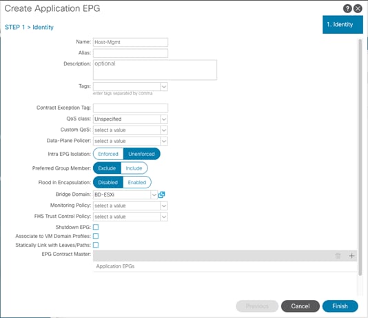
4. Click Finish to complete creating the EPG.
5. In the left menu, expand the newly created EPG, right-click Domains and select Add L2 External Domain Association.
6. Select the CHV-Site1-UCS L2 External Domain Profile.
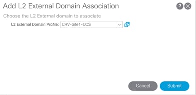
7. Click Submit.
8. In the left menu, right-click Static Ports and select Deploy Static EPG on PC, VPC, or Interface.
9. Select the Virtual Port Channel Path Type, then for Path select the vPC for the first UCS Fabric Interconnect.
10. For Port Encap leave VLAN selected and fill in the UCS Host VLAN ID <419>.
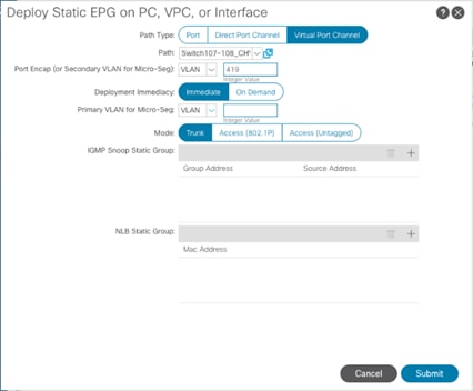
11. Set the Deployment Immediacy to Immediate and click Submit.
12. Repeat steps 9-12 to add the Static Port mapping for the second UCS Fabric Interconnect.
Create EPG for vMotion
This EPG will connect the ESXi hosts for communicating vMotion traffic.
To create the EPG for vMotion, follow these steps:
1. In the left pane, expand the Application Profiles and right-click the Infra Application Profile and select Create Application EPG.
2. Name the EPG vMotion.
3. From the Bridge Domain drop-down list, select Bridge Domain BD-vMotion.
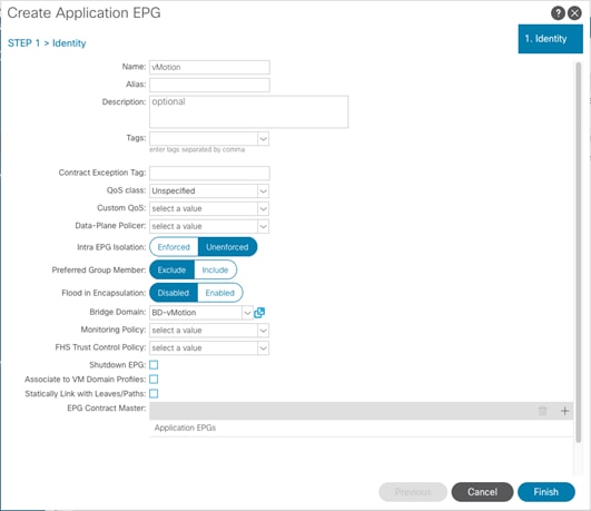
4. Click Finish to complete creating the EPG.
5. In the left menu, expand the newly created EPG, right-click Domains and select Add L2 External Domain Association.
6. Select the CHV-Site1-UCS L2 External Domain Profile.
7. Click Submit.
8. In the left menu, right-click Static Ports and select Deploy Static EPG on PC, VPC, or Interface.
9. Select the Virtual Port Channel Path Type, then for Path select the vPC for the first UCS Fabric Interconnect.
10. For Port Encap leave VLAN selected and fill in the UCS vMotion VLAN ID <519>.

11. Set the Deployment Immediacy to Immediate and click Submit.
12. Repeat steps 9-11 to add the Static Port mapping for the second UCS Fabric Interconnect.
The MDS configuration implements a common redundant physical fabric design with fabrics represented as “A” and “B”. The validating lab provided a basic MDS fabric supporting the VSP Storage System and the UCS domain within the SAN environment. Larger deployments may require a multi-tier core-edge or edge-core-edge design with port channels connecting the differing layers of the topology. Further discussion of these kinds of topologies, as well as considerations in implementing more complex SAN environments can be found in this white paper: https://www.cisco.com/c/en/us/products/collateral/storage-networking/mds-9700-series-multilayer-directors/white-paper-c11-729697.pdf
The configuration steps described below are implemented for the Cisco MDS 9706 but are similar to steps required for other Cisco MDS 9000 series switches that may be appropriate for a deployment. When making changes to the design that comply with the compatibility matrices of Cisco and Hitachi, it is required to consult the appropriate configuration documents of the differing equipment to confirm the correct implementation steps.
Physical Connectivity
Physical cabling should be completed by following the diagram and table references section the Physical Cabling section found previously in the document.
Initial MDS Configuration Dialogue
Complete this dialogue on each switch, using a serial connection to the console port of the switch, unless Power on Auto Provisioning is being used:
---- System Admin Account Setup ----
Do you want to enforce secure password standard (yes/no) [y]: <enter>
Enter the password for "admin": <<var_password>>
Confirm the password for "admin": <<var_password>>
---- Basic System Configuration Dialog ----
This setup utility will guide you through the basic configuration of
the system. Setup configures only enough connectivity for management
of the system.
Please register Cisco MDS 9000 Family devices promptly with your
supplier. Failure to register may affect response times for initial
service calls. MDS devices must be registered to receive entitled
support services.
Press Enter at anytime to skip a dialog. Use ctrl-c at anytime
to skip the remaining dialogs.
Would you like to enter the basic configuration dialog (yes/no): yes
Create another login account (yes/no) [n]: <enter>
Configure read-only SNMP community string (yes/no) [n]: <enter>
Configure read-write SNMP community string (yes/no) [n]: <enter>
Enter the switch name : <<var_mds_A_hostname>>|<<var_mds_B_hostname>>
Continue with Out-of-band (mgmt0) management configuration? (yes/no) [y]: <enter>
Mgmt0 IPv4 address : <<var_mds_A_mgmt_ip>>|<<var_mds_B_mgmt_ip>>
Mgmt0 IPv4 netmask : <<var_oob_netmask>>
Configure the default gateway? (yes/no) [y]: <enter>
IPv4 address of the default gateway : <<var_oob_gateway>>
Configure advanced IP options? (yes/no) [n]: <enter>
Enable the ssh service? (yes/no) [y]: <enter>
Type of ssh key you would like to generate (dsa/rsa) [rsa]: <enter>
Number of rsa key bits <1024-2048> [1024]: <enter>
Enable the telnet service? (yes/no) [n]: <enter>
Configure congestion/no_credit drop for fc interfaces? (yes/no) [y]: <enter>
Enter the type of drop to configure congestion/no_credit drop? (con/no) [c]: <enter>
Enter milliseconds in multiples of 10 for congestion-drop for logical-type edge
in range (<200-500>/default), where default is 500. [d]: <enter>
Congestion-drop for logical-type core must be greater than or equal to
Congestion-drop for logical-type edge. Hence, Congestion drop for
logical-type core will be set as default.
Enable the http-server? (yes/no) [y]: <enter>
Configure clock? (yes/no) [n]: y
Clock config format [HH:MM:SS Day Mon YYYY] [example: 18:00:00 1 november 2012]: <enter>
Enter clock config :17:26:00 2 january 2019
Configure timezone? (yes/no) [n]: y
Enter timezone config [PST/MST/CST/EST] :EST
Enter Hrs offset from UTC [-23:+23] : <enter>
Enter Minutes offset from UTC [0-59] : <enter>
Configure summertime? (yes/no) [n]: <enter>
Configure the ntp server? (yes/no) [n]: y
NTP server IPv4 address : <var_oob_ntp>
Configure default switchport interface state (shut/noshut) [shut]: <enter>
Configure default switchport trunk mode (on/off/auto) [on]: <enter>
Configure default switchport port mode F (yes/no) [n]: <enter>
Configure default zone policy (permit/deny) [deny]: <enter>
Enable full zoneset distribution? (yes/no) [n]: <enter>
Configure default zone mode (basic/enhanced) [basic]: <enter>
The following configuration will be applied:
password strength-check
switchname aa19-9706-1
interface mgmt0
ip address 192.168.168.18 255.255.255.0
no shutdown
ip default-gateway 192.168.168.254
ssh key rsa 1024 force
feature ssh
no feature telnet
system timeout congestion-drop default logical-type edge
system timeout congestion-drop default logical-type core
feature http-server
clock set 17:26:00 2 january 2019
clock timezone EST 0 0
ntp server 192.168.168.254
system default switchport shutdown
system default switchport trunk mode on
no system default zone default-zone permit
no system default zone distribute full
no system default zone mode enhanced
Would you like to edit the configuration? (yes/no) [n]: <enter>
Use this configuration and save it? (yes/no) [y]: <enter>
Cisco MDS Switch Configuration
Cisco MDS 9706 A and Cisco MDS 9706 B
To enable the correct features on the Cisco MDS switches, follow these steps:
1. Log in as admin.
2. Run the following commands:
aa19-9706-1&2# configure terminal
aa19-9706-1&2(config)# feature npiv
aa19-9706-1&2(config)# feature fport-channel-trunk
aa19-9706-1&2(config)# feature lldp
aa19-9706-1&2(config)# device-alias mode enhanced
aa19-9706-1&2(config)# device-alias commit
![]() The device-alias commit will trigger a warning that this command will clear existing device aliases on attached fabrics, which should not impact the initial deployment instructions being followed here.
The device-alias commit will trigger a warning that this command will clear existing device aliases on attached fabrics, which should not impact the initial deployment instructions being followed here.
Configure Individual Ports
Cisco MDS 9706 A
To configure individual ports and port-channels for switch A, follow these steps:
From the global configuration mode, run the following commands:
aa19-9706-1(config)# interface fc1/5
aa19-9706-1(config-if)# switchport description <var_ucs_6454_clustername>-a:1/1
aa19-9706-1(config-if)# channel-group 15 force
aa19-9706-1(config-if)# no shutdown
aa19-9706-1(config-if)#
aa19-9706-1(config-if)# interface fc1/6
aa19-9706-1(config-if)# switchport description <var_ucs_6454_clustername>-a:1/2
aa19-9706-1(config-if)# channel-group 15 force
aa19-9706-1(config-if)# no shutdown
aa19-9706-1(config-if)#
aa19-9706-1(config-if)# interface fc1/11
aa19-9706-1(config-if)# switchport description <vsp-g370>-a:CL 1-A
aa19-9706-1(config-if)# no shutdown
aa19-9706-1(config-if)#
aa19-9706-1(config-if)# interface fc1/12
aa19-9706-1(config-if)# switchport description <vsp-g370>-a:CL 2-B
aa19-9706-1(config-if)# no shutdown
aa19-9706-1(config-if)#
aa19-9706-1(config-if)# interface port-channel 15
aa19-9706-1(config-if)# switchport description <var_ucs_6454_clustername>-portchannel
aa19-9706-1(config-if)# channel mode active
aa19-9706-1(config-if)# exit
Create Port Descriptions - Fabric B
To configure individual ports and port-channels for switch B, follow these steps:
From the global configuration mode, run the following commands:
aa19-9706-2(config)# interface fc1/5
aa19-9706-2(config-if)# switchport description <var_ucs_6454_clustername>-b:1/1
aa19-9706-2(config-if)# channel-group 15 force
aa19-9706-2(config-if)# no shutdown
aa19-9706-2(config-if)#
aa19-9706-2(config-if)# interface fc1/6
aa19-9706-2(config-if)# switchport description <var_ucs_6454_clustername>-b:1/2
aa19-9706-2(config-if)# channel-group 15 force
aa19-9706-2(config-if)# no shutdown
aa19-9706-2(config-if)#
aa19-9706-2(config-if)# interface fc1/11
aa19-9706-2(config-if)# switchport description <vsp-g370>-a:CL 3-B
aa19-9706-2(config-if)# no shutdown
aa19-9706-2(config-if)#
aa19-9706-2(config-if)# interface fc1/12
aa19-9706-2(config-if)# switchport description <vsp-g370>-a:CL 4-A
aa19-9706-2(config-if)# no shutdown
aa19-9706-2(config-if)#
aa19-9706-2(config-if)# interface port-channel 15
aa19-9706-2(config-if)# switchport description <var_ucs_6454_clustername>-portchannel
aa19-9706-2(config-if)# channel mode active
aa19-9706-2(config-if)# exit
Create VSANs
Cisco MDS 9706 A
To create the necessary VSANs for fabric A and add ports, follow these steps:
From the global configuration mode, run the following commands:
aa19-9706-1(config)# vsan database
aa19-9706-1(config-vsan-db)# vsan <var_vsan_a_id>
aa19-9706-1(config-vsan-db)# vsan <var_vsan_a_id> name Fabric-A
aa19-9706-1(config-vsan-db)# exit
aa19-9706-1(config)# zone smart-zoning enable vsan <var_vsan_a_id>
aa19-9706-1(config)# vsan database
aa19-9706-1(config-vsan-db)# vsan <var_vsan_a_id> interface fc1/11
aa19-9706-1(config-vsan-db)# vsan <var_vsan_a_id> interface fc1/12
aa19-9706-1(config-vsan-db)# vsan <var_vsan_a_id> interface port-channel 15
aa19-9706-1(config-vsan-db)# end
aa19-9706-1# copy run start
![]() For the fc 1/x vsan assignments above and below, there will be a warning message about traffic impact for these changes, which can be ignored. The option of “y” to continue should be specified if asked.
For the fc 1/x vsan assignments above and below, there will be a warning message about traffic impact for these changes, which can be ignored. The option of “y” to continue should be specified if asked.
Cisco MDS 9706 B
To create the necessary VSANs for fabric B and add ports to them, follow these steps:
From the global configuration mode, run the following commands:
aa19-9706-2(config)# vsan database
aa19-9706-2(config-vsan-db)#vsan <var_vsan_b_id>
aa19-9706-2(config-vsan-db)#vsan <var_vsan_b_id> name Fabric-B
aa19-9706-2(config-vsan-db)#exit
aa19-9706-2(config)# zone smart-zoning enable vsan <var_vsan_b_id>
aa19-9706-2(config)# vsan database
aa19-9706-2(config-vsan-db)#vsan <var_vsan_b_id> interface fc1/11
aa19-9706-2(config-vsan-db)#vsan <var_vsan_b_id> interface fc1/12
aa19-9706-2(config-vsan-db)#vsan <var_vsan_b_id> interface port-channel 15
aa19-9706-2(config-vsan-db)# end
aa19-9706-2# copy run start
In order for Hitachi Virtual Storage Platform fibre channel ports to be exposed properly to the Cisco UCS components, modification of the ports from their default values must be performed. Prior to beginning this section, ensure that you have credentials on the Hitachi Virtual Storage Platform that have at least the Administrator role permissions within Hitachi Storage Navigator. Your partner or Hitachi services personnel provide credentials to your Hitachi Virtual Storage Platform after initial setup and configuration of the storage system.
To configure the fibre channel ports within the VSP storage system, follow these steps:
1. Access Hitachi Storage Navigator through a web browser.
2. VSP Fx00 Models and VSP Gx00 Models: https://<IP of Storage System SVP>/dev/storage/886000<Serial Number of Storage System>/emergency.do – for example, if Storage System SVP IP address is 10.0.0.2 and Serial Number of Storage System is 451200, the URL would be:
https://10.0.0.2/dev/storage/88600451200/emergency.do
3. Log into Hitachi Storage Navigator.

4. From the left Explorer pane, select the Storage Systems tab.
5. Expand the storage system being configured. Highlight the Ports/Host Groups/iSCSI Targets element in the navigation tree, then click the Ports tab in the main configuration pane.
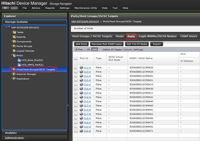
6. Select the checkboxes for the ports being used within the solution, then click the Edit Ports button to instantiate the Edit Ports dialog box.
7. Select checkboxes to edit the following settings to modify the selected ports:
- Port Attribute: Target
- Port Security: Enable
- Port Speed: Auto
- Fabric: ON
- Connection Type: P-to-P
![]() Port Attribute will only appear as an option in VSP G1500 Edit Ports dialogue.
Port Attribute will only appear as an option in VSP G1500 Edit Ports dialogue.
8. Example ports used in the Cisco UCS 6454 to VSP G370 used in this design are listed in Table 22 .
Table 22 VSP G370 to UCS Ports
| Local Device |
Local Port |
Connection |
Remote Device |
Remote Port |
| Hitachi VSP G370
|
CL 1-A |
32Gb FC |
Cisco UCS 6454 FI A |
FC 1/1 |
| CL 2-B |
32Gb FC |
Cisco UCS 6454 FI A |
FC 1/2 |
|
| CL 3-B |
32Gb FC |
Cisco UCS 6454 FI B |
FC 1/1 |
|
| CL 4-A |
32Gb FC |
Cisco UCS 6454 FI B |
FC 1/2 |
Figure 6 VSP G370 Edit Ports Pop-Up Window
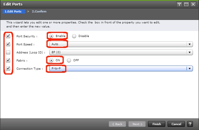
9. Click OK for any warning that appears.
10. Click Finish.
11. Review the changes to be made and check the Go to tasks window for status box, then click the Apply button.
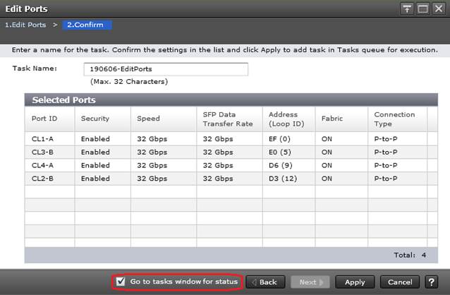
12. The Task view window will appear and show the completion status of the Edit Ports task. Wait until the task status shows Complete and proceed to the next section.
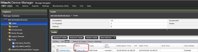
This section explains the configuration of the Cisco UCS 6454 Fabric Interconnects used in this UCP solution. Similar to the Nexus and MDS Switches previously explained, some changes may be appropriate for your environment, however you should be careful since any deviation from our instructions may lead to an improper configuration.
Physical Connectivity
Physical cabling should be completed by following the diagram and table references section the Physical Cabling section found previously in the document.
Upgrade Cisco UCS Manager Software to Version 4.0(4b)
This document assumes the use of Cisco UCS 4.0(4b). To upgrade the Cisco UCS Manager software and the Cisco UCS Fabric Interconnect software to version 4.0(4b), go to Cisco UCS Manager Install and Upgrade Guides.
Cisco UCS Base Configuration
The initial configuration dialogue for the Cisco UCS 6454 Fabric Interconnects will be provided to the first fabric interconnect and the second fabric interconnect will receive most settings after joining the cluster.
To begin the configuration, follow these steps:
1. To start the configuration of the Fabric Interconnect A, connect to the console of the fabric interconnect and step through the Basic System Configuration Dialogue:
---- Basic System Configuration Dialog ----
This setup utility will guide you through the basic configuration of
the system. Only minimal configuration including IP connectivity to
the Fabric interconnect and its clustering mode is performed through these steps.
Type Ctrl-C at any time to abort configuration and reboot system.
To back track or make modifications to already entered values,
complete input till end of section and answer no when prompted
to apply configuration.
Enter the configuration method. (console/gui) ? console
Enter the setup mode; setup newly or restore from backup. (setup/restore) ? setup
You have chosen to setup a new Fabric interconnect. Continue? (y/n): y
Enforce strong password? (y/n) [y]: <Enter>
Enter the password for "admin": <<var_password>>
Confirm the password for "admin": <<var_password>>
Is this Fabric interconnect part of a cluster(select 'no' for standalone)? (yes/no) [n]: y
Enter the switch fabric (A/B) []: A
Enter the system name: <<var_ucs_6454_clustername>>
Physical Switch Mgmt0 IP address : <<var_ucsa_mgmt_ip>>
Physical Switch Mgmt0 IPv4 netmask : <<var_oob_mgmt_mask>>
IPv4 address of the default gateway : <<var_oob_gateway>>
Cluster IPv4 address : <<var_ucs_mgmt_vip>>
Configure the DNS Server IP address? (yes/no) [n]: y
DNS IP address : <<var_nameserver_ip>>
Configure the default domain name? (yes/no) [n]: y
Default domain name : <<var_dns_domain_name>>
Join centralized management environment (UCS Central)? (yes/no) [n]: <Enter>
Following configurations will be applied:
Switch Fabric=A
System Name=AA19-6454
Enforced Strong Password=yes
Physical Switch Mgmt0 IP Address=10.1.168.16
Physical Switch Mgmt0 IP Netmask=255.255.255.0
Default Gateway=10.1.168.254
Ipv6 value=0
DNS Server=10.1.168.9
Domain Name=ucp.cisco.com
Cluster Enabled=yes
Cluster IP Address=10.1.168.15
NOTE: Cluster IP will be configured only after both Fabric Interconnects are initialized.
UCSM will be functional only after peer FI is configured in clustering mode.
Apply and save the configuration (select 'no' if you want to re-enter)? (yes/no): yes
Applying configuration. Please wait.
Configuration file - Ok
![]() Wait for the appearance of a login prompt on UCS FI A before proceeding to B.
Wait for the appearance of a login prompt on UCS FI A before proceeding to B.
2. Continue the configuration on the console of the Fabric Interconnect B:
Enter the configuration method. (console/gui) [console] ?
Installer has detected the presence of a peer Fabric interconnect. This Fabric interconnect will be added to the cluster. Continue (y/n) ? y
Enter the admin password of the peer Fabric interconnect:
Connecting to peer Fabric interconnect... done
Retrieving config from peer Fabric interconnect... done
Peer Fabric interconnect Mgmt0 IPv4 Address: 10.1.168.16
Peer Fabric interconnect Mgmt0 IPv4 Netmask: 255.255.255.0
Cluster IPv4 address : 10.1.168.15
Peer FI is IPv4 Cluster enabled. Please Provide Local Fabric Interconnect Mgmt0 IPv4 Address
Physical Switch Mgmt0 IP address : 10.1.168.17
Apply and save the configuration (select 'no' if you want to re-enter)? (yes/no): yes
Applying configuration. Please wait.
Cisco UCS Manager Setup
Log into Cisco UCS Manager
To log into Cisco Unified Computing System (Cisco UCS) environment and Cisco UCS Manager (UCSM), follow these steps:
1. Open a web browser and navigate to the Cisco UCS fabric interconnect cluster address.
2. Click the Launch UCS Manager link within the opening page.
3. If prompted to accept security certificates, accept as necessary.
4. When the Cisco UCS Manager login is prompted, enter admin as the user name and enter the administrative password.
5. Click Login to log into Cisco UCS Manager.
Anonymous Reporting
During the first connection to the Cisco UCS Manager GUI, a pop-up window will appear to allow for the configuration of Anonymous Reporting to Cisco on use to help with future development. To create anonymous reporting, complete the following step:
1. In the Anonymous Reporting window, select whether to send anonymous data to Cisco for improving future products, and provide the appropriate SMTP server gateway information if configuring:
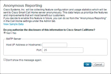
If you want to enable or disable Anonymous Reporting at a later date, it can be found within Cisco UCS Manager under: Admin -> Communication Management -> Call Home, which has a tab on the far right for Anonymous Reporting.
Synchronize Cisco UCS to NTP
To synchronize the Cisco UCS environment to the NTP server, follow these steps:
1. In Cisco UCS Manager, click the Admin tab in the navigation pane.
2. Select Timezone Management drop-down list and click Timezone.
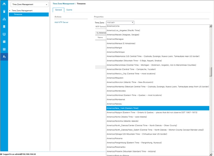
3. In the Properties pane, select the appropriate time zone in the Timezone menu.
4. Click Save Changes, and then click OK.
5. Click Add NTP Server.
6. Enter <<var_oob_ntp>> and click OK.
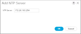
7. Click OK.
Configure Cisco UCS Servers
Edit Chassis Discovery Policy
Setting the discovery policy simplifies the addition of B-Series Cisco UCS chassis. To modify the chassis discovery policy, follow these steps:
1. In Cisco UCS Manager, click the Equipment tab in the navigation pane and select Policies in the list on the left under the drop-down.
2. Under Global Policies, set the Chassis/FEX Discovery Policy to match the minimum number of uplink ports that should be cabled between the chassis or fabric extenders (FEXes) and the fabric interconnects.
3. Set the Link Grouping Preference to Port Channel.
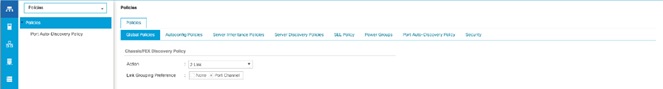
![]() If varying numbers of links between chassis and the Fabric Interconnects will be used, leave Action set to 1 Link.
If varying numbers of links between chassis and the Fabric Interconnects will be used, leave Action set to 1 Link.
4. Leave other settings alone or change if appropriate to your environment.
5. Click Save Changes.
6. Click OK.
Enable Port Auto-Discovery Policy
Setting the port auto-discovery policy enables automatic discovery of Cisco UCS B-Series chassis server ports. To modify the port auto-discovery policy, follow these steps:
1. In Cisco UCS Manager, click Equipment , select All > Equipment in the Navigation Pane, and select the Policies tab on the right.
2. Under Port Auto-Discovery Policy, set Auto Configure Server Port to Enabled.
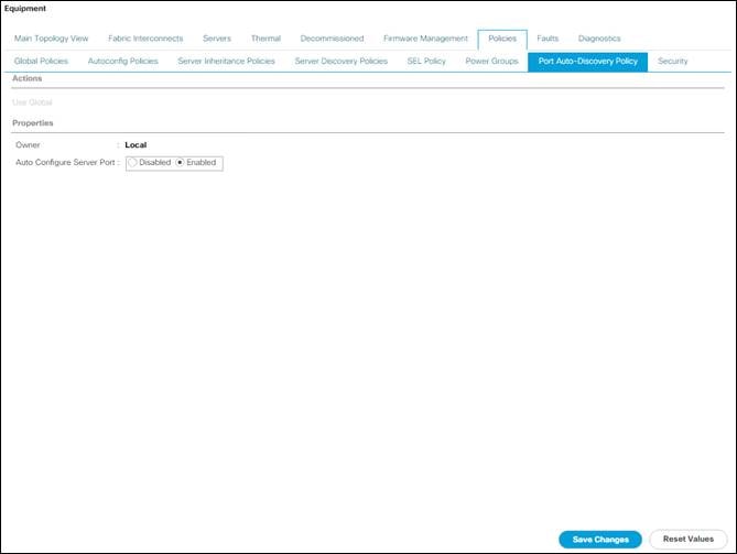
3. Click Save Changes and then click OK.
Enable Info Policy for Neighbor Discovery
Enabling the info policy enables Fabric Interconnect neighbor information to be displayed. To modify the info policy, follow these steps:
1. In Cisco UCS Manager, click Equipment, select All > Equipment in the Navigation Pane, and select the Policies tab on the right.
2. Scroll down to Info Policy and select Enabled for Action.

3. Click Save Changes and then OK.
4. Under Equipment, select Fabric Interconnect A (primary). On the right, select the Neighbors tab. CDP information is shown under the LAN tab and LLDP information is shown under the LLDP tab.
Enable Server and Uplink Ports
To enable server and uplink ports, follow these steps:
1. In Cisco UCS Manager, click the Equipment tab in the navigation pane.
2. Select Equipment > Fabric Interconnects > Fabric Interconnect A (primary) > Fixed Module.
3. Expand Ethernet Ports.
4. Select the ports that are connected to the chassis, right-click them, and select “Configure as Server Port.”
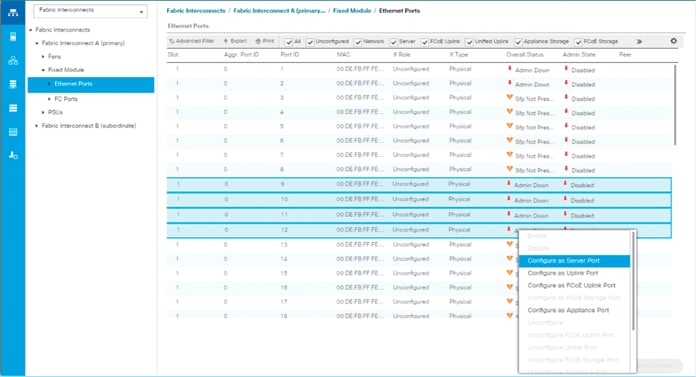
5. Click Yes to confirm server ports and click OK.
6. Verify that the ports connected to the chassis are now configured as server ports.
7. Select ports 47 and 48 that are connected to the Cisco Nexus switches, right-click them, and select Configure as Uplink Port.
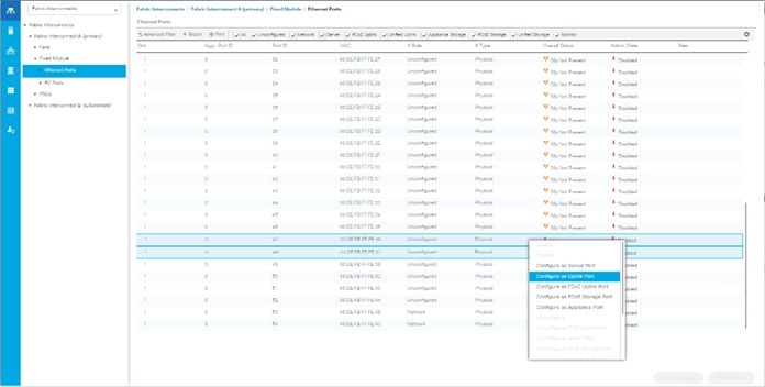
8. Click Yes to confirm uplink ports and click OK.
9. Select Equipment > Fabric Interconnects > Fabric Interconnect B (subordinate) > Fixed Module.
10. Expand Ethernet Ports.
11. Select the ports that are connected to the chassis, right-click them and select Configure as Server Port.
12. Click Yes to confirm server ports and click OK.
13. Select ports 47 and 48 that are connected to the Cisco Nexus switches, right-click them, and select Configure as Uplink Port.
14. Click Yes to confirm the uplink ports and click OK.
Acknowledge Cisco UCS Chassis
To acknowledge all Cisco UCS chassis, follow these steps:
1. In Cisco UCS Manager, click the Equipment tab in the navigation pane.
2. Expand Chassis and select each chassis that is listed.
3. Right-click each chassis and select Acknowledge Chassis.
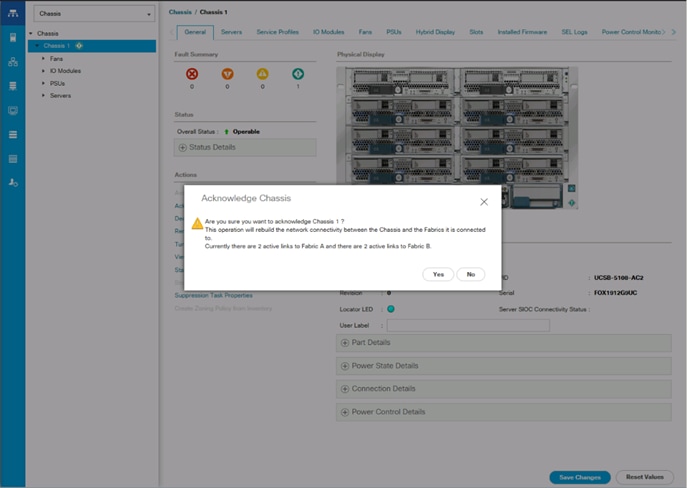
4. Click Yes and then click OK to complete acknowledging the chassis.
Create Pools
Create MAC Address Pools
To configure the necessary MAC address pools for the Cisco UCS environment, follow these steps:
1. In Cisco UCS Manager, click the LAN tab in the navigation pane.
2. Select Pools > root.
![]() In this procedure, two MAC address pools are created; one for each switching fabric.
In this procedure, two MAC address pools are created; one for each switching fabric.
3. Right-click MAC Pools under the root organization.
4. Select Create MAC Pool to create the MAC address pool.
5. Enter MAC_Pool_A as the name of the MAC pool.
6. Optional: Enter a description for the MAC pool.
7. Select Sequential as the option for Assignment Order.

8. Click Next.
9. Click Add.
10. Specify a starting MAC address.
![]() For Cisco UCS deployments, the recommendation is to place 0A in the next-to-last octet of the starting MAC address to identify all of the MAC addresses as fabric A addresses. In our example, we have carried forward the of information of also embedding and FI number reference of 54(for UCS 6454) giving us 00:25:B5:54:0A:00 as our first MAC address.
For Cisco UCS deployments, the recommendation is to place 0A in the next-to-last octet of the starting MAC address to identify all of the MAC addresses as fabric A addresses. In our example, we have carried forward the of information of also embedding and FI number reference of 54(for UCS 6454) giving us 00:25:B5:54:0A:00 as our first MAC address.
11. Specify a size for the MAC address pool that is sufficient to support the available blade or server resources.
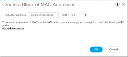
12. Click OK.
13. Click Finish.
14. In the confirmation message, click OK.
15. Right-click MAC Pools under the root organization.
16. Select Create MAC Pool to create the MAC address pool.
17. Enter MAC_Pool_B as the name of the MAC pool.
18. Optional: Enter a description for the MAC pool.
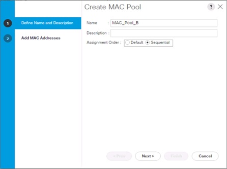
19. Click Next.
20. Click Add.
21. Specify a starting MAC address.
![]() For Cisco UCS deployments, it is recommended to place 0B in the next to last octet of the starting MAC address to identify all the MAC addresses in this pool as fabric B addresses. We carried forward the information of embedding and the FI number reference of 54 giving us 00:25:B5:54:0A:00 as our first MAC address.
For Cisco UCS deployments, it is recommended to place 0B in the next to last octet of the starting MAC address to identify all the MAC addresses in this pool as fabric B addresses. We carried forward the information of embedding and the FI number reference of 54 giving us 00:25:B5:54:0A:00 as our first MAC address.
22. Specify a size for the MAC address pool that is sufficient to support the available blade or server resources.

23. Click OK.
24. Click Finish.
25. In the confirmation message, click OK.
Create UUID Suffix Pool
To configure the necessary universally unique identifier (UUID) suffix pool for the Cisco UCS environment, follow these steps:
1. In Cisco UCS Manager, click the Servers tab in the navigation pane.
2. Select Pools > root.
3. Right-click UUID Suffix Pools.
4. Select Create UUID Suffix Pool.
5. Enter UUID_Pool as the name of the UUID suffix pool.
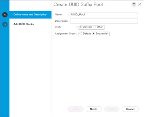
6. Optional: Enter a description for the UUID suffix pool.
7. Keep the prefix at the derived option.
8. Select Sequential for the Assignment Order.
9. Click Next.
10. Click Add to add a block of UUIDs.
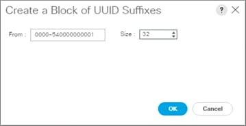
![]() The starting From number (0000-54) has been adjusted to give it a differentiator from other UCS domains that may be adjacent.
The starting From number (0000-54) has been adjusted to give it a differentiator from other UCS domains that may be adjacent.
11. Specify a size for the UUID block that is sufficient to support the available blade or server resources.
12. Click OK.
13. Click Finish.
14. Click OK.
Create Server Pool
To configure the necessary server pool for the Cisco UCS environment, follow these steps:
![]() Consider creating unique server pools to achieve the granularity that is required in your environment.
Consider creating unique server pools to achieve the granularity that is required in your environment.
1. In Cisco UCS Manager, click the Servers tab in the navigation pane.
2. Select Pools > root.
3. Right-click Server Pools.
4. Select Create Server Pool.
5. Enter Infra_Pool as the name of the server pool.
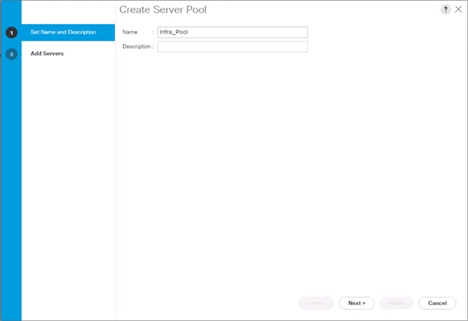
6. Optional: Enter a description for the server pool.
7. Click Next.
8. Select two (or more) servers to be used for the VMware cluster and click >> to add them to the Infra_Pool server pool.
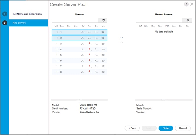
9. Click Finish.
10. Click OK.
Add a Block of IP Addresses for KVM Access
To create a block of IP addresses for in band server Keyboard, Video, Mouse (KVM) access in the Cisco UCS environment, follow these steps:
1. In Cisco UCS Manager, click the LAN tab in the navigation pane.
2. Select Pools > root > IP Pools.
3. Right-click IP Pool ext-mgmt and select Create Block of IPv4 Addresses.
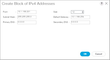
4. Enter the starting IP address of the block and the number of IP addresses required, and the subnet and gateway information.
5. Click OK to create the block of IPs.
6. Click OK.
Create a WWNN Pool
To configure the necessary WWNN pool for the Cisco UCS environment, follow these steps on Cisco UCS Manager:
1. Select the SAN tab on the left.
2. Select Pools > root.
3. Right-click WWNN Pools under the root organization.
4. Select Create WWNN Pool to create the WWNN pool.
5. Enter WWNN_Pool for the name of the WWNN pool.
6. Optional: Enter a description for the WWNN pool.
7. Select Sequential for Assignment Order.
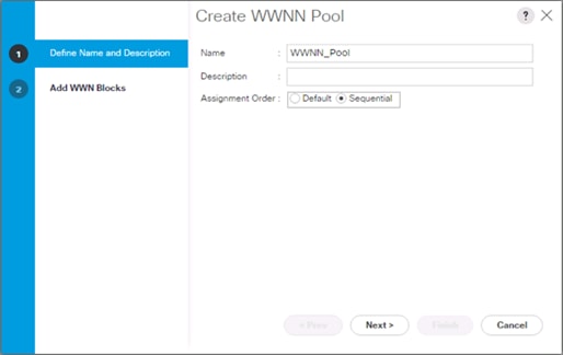
8. Click Next.
9. Click Add.
10. Modify the From field as necessary for the UCS Environment.
![]() Modifications of the WWN block, as well as the WWPN and MAC Addresses, can convey identifying information for the Cisco UCS domain. Within the From field in our example, the 6th octet was changed from 00 to 54 to represent as identifying information for the 6454 Cisco UCS domain.
Modifications of the WWN block, as well as the WWPN and MAC Addresses, can convey identifying information for the Cisco UCS domain. Within the From field in our example, the 6th octet was changed from 00 to 54 to represent as identifying information for the 6454 Cisco UCS domain.
![]() When you have multiple Cisco UCS domains sitting in adjacency, it is important that these blocks, the WWNN, WWPN, and MAC hold differing values between each set.
When you have multiple Cisco UCS domains sitting in adjacency, it is important that these blocks, the WWNN, WWPN, and MAC hold differing values between each set.
11. Specify a size of the WWNN block sufficient to support the available server resources.

12. Click OK.
13. Click Finish to create the WWNN Pool.
14. Click OK.
Create WWPN Pools
To configure the necessary WWPN pools for the Cisco UCS environment, follow these steps:
1. In Cisco UCS Manager, click the SAN tab in the navigation pane.
2. Select Pools > root.
3. In this procedure, two WWPN pools are created, one for each switching fabric.
4. Right-click WWPN Pools under the root organization.
5. Select Create WWPN Pool to create the WWPN pool.
6. Enter WWPN_Pool_A as the name of the WWPN pool.
7. Optional: Enter a description for the WWPN pool.
8. Select Sequential for Assignment Order.
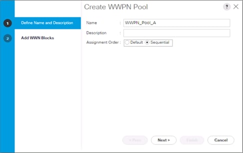
9. Click Next.
10. Click Add.
11. Specify a starting WWPN.
![]() For the solution, the recommendation is to place 0A in the next-to-last octet of the starting WWPN to identify all of the WWPNs as fabric A addresses. Merging this with the pattern we used for the WWNN, we see a WWPN block starting with 20:00:00:25:B5:54:0A:00.
For the solution, the recommendation is to place 0A in the next-to-last octet of the starting WWPN to identify all of the WWPNs as fabric A addresses. Merging this with the pattern we used for the WWNN, we see a WWPN block starting with 20:00:00:25:B5:54:0A:00.
12. Specify a size for the WWPN pool that is sufficient to support the available blade or server resources.

13. Click OK.
14. Click Finish.
15. In the confirmation message, click OK.
16. Right-click WWPN Pools under the root organization.
17. Select Create WWPN Pool to create the WWPN pool.
18. Enter WWPN_Pool_B as the name of the WWPN pool.
19. Optional: Enter a description for the WWPN pool.
20. Select Sequential for Assignment Order.

21. Click Next.
22. Click Add.
23. Specify a starting WWPN.
![]() For the solution, the recommendation is to place 0B in the next-to-last octet of the starting WWPN to identify all of the WWPNs as fabric A addresses. Merging this with the pattern we used for the WWNN, we see a WWPN block starting with 20:00:00:25:B5:54:0B:00.
For the solution, the recommendation is to place 0B in the next-to-last octet of the starting WWPN to identify all of the WWPNs as fabric A addresses. Merging this with the pattern we used for the WWNN, we see a WWPN block starting with 20:00:00:25:B5:54:0B:00.
24. Specify a size for the WWPN address pool that is sufficient to support the available blade or server resources.
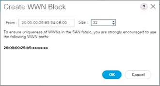
25. Click OK.
26. Click Finish.
27. In the confirmation message, click OK.
Set Packages and Policies
Create Host Firmware Package
Firmware management policies allow the administrator to select the corresponding packages for a given server configuration. These policies often include packages for adapter, BIOS, board controller, FC adapters, host bus adapter (HBA) option ROM, and storage controller properties.
To create a firmware management policy for a given server configuration in the Cisco UCS environment, follow these steps:
1. In Cisco UCS Manager, click the Servers tab in the navigation pane.
2. Select Policies > root.
3. Expand Host Firmware Packages.
4. Select default.
5. In the Actions pane, select Modify Package Versions.
6. Select the version 4.0(4b)B for the Blade Package, and optionally set version 4.0(4b)C for the Rack Package.
7. Leave Excluded Components with only Local Disk selected.
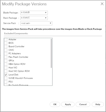
8. Click OK to modify the host firmware package and OK again to acknowledge the changes.
Create Server Pool Qualification Policy (Optional)
To create an optional server pool qualification policy for the Cisco UCS environment, follow these steps:
![]() This example creates a policy for Cascade Lake Processor equipped servers for a server pool.
This example creates a policy for Cascade Lake Processor equipped servers for a server pool.
1. In Cisco UCS Manager, click the Servers tab in the navigation pane.
2. Select Policies > root.
3. Right-click Server Pool Policy Qualifications.
4. Select Create Server Pool Policy Qualification.
5. Name the policy UCS-CascadeLake.
6. Select Create CPU/Cores Qualifications.
7. In the PID (RegEx) field enter: UCS-CPU-I42*.
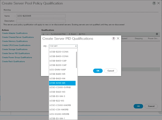
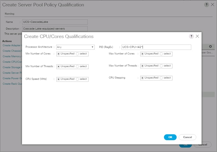
8. Click OK.
9. Optionally, select additional qualifications to refine server selection parameters for the server pool.
10. Click OK to create the policy then click OK for the confirmation.
Download the Image for ESXi 6.7 U2
The VMware Cisco Custom Image will need to be downloaded for use during installation by manual access to the UCS KVM vMedia, or through a vMedia Policy explained in the following subsection.
To download the Cisco Custom Image, follow these steps:
1. Click the following link: VMware vSphere Hypervisor Cisco Custom Image (ESXi) 6.7 U2.
2. You will need a user id and password on vmware.com to download this software.
3. Download the .iso file.
Create vMedia Policy for VMware ESXi 6.7 U2 Install Boot (optional, if manually attaching ISO through KVM)
A separate HTTP web server is required to automate the availability of the ESXi image to each Service Profile on first power on. The creation of this web server is not included in this document but can be any existing web server capable of serving files through HTTP that are accessible on the OOB network that the ESXi image can be placed upon.
Place the Cisco Custom Image VMware ESXi 6.7 U2 ISO on the HTTP server and follow these steps to create a vMedia Policy:
1. In Cisco UCS Manager, select Servers on the left.
2. Select Policies > root.
3. Right-click vMedia Policies.
4. Select Create vMedia Policy.
5. Name the policy ESXi-6.7U2-HTTP.
6. Enter “Mounts ISO for ESXi 6.7 U2” in the Description field.
7. Click Add.
8. Name the mount ESXi-6.7U2-HTTP.
9. Select the CDD Device Type.
10. Select the HTTP Protocol.
11. Enter the IP Address of the web server.
![]() Since DNS server IPs were not entered into the KVM IP earlier, it is necessary to enter the IP of the web server instead of the hostname.
Since DNS server IPs were not entered into the KVM IP earlier, it is necessary to enter the IP of the web server instead of the hostname.
12. Leave “None” selected for Image Name Variable.
13. Enter VMware_ESXi_6.7.0_13006603_Custom_Cisco_6.7.2.1.iso as the Remote File name.
14. Enter the web server path to the ISO file in the Remote Path field.
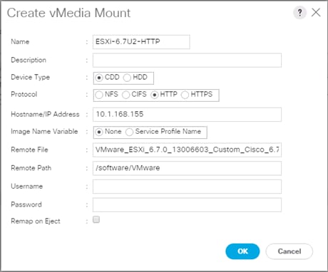
15. Click OK to create the vMedia Mount.
16. Click OK then OK again to complete creating the vMedia Policy.
![]() For any new servers added to the Cisco UCS environment the vMedia service profile template can be used to install the ESXi host. On first boot the host will boot into the ESXi installer. After ESXi is installed, the vMedia will not be referenced as long as the boot disk is accessible.
For any new servers added to the Cisco UCS environment the vMedia service profile template can be used to install the ESXi host. On first boot the host will boot into the ESXi installer. After ESXi is installed, the vMedia will not be referenced as long as the boot disk is accessible.
Create Server BIOS Policy
To create a server BIOS policy for the Cisco UCS environment, follow these steps:
1. In Cisco UCS Manager, click Servers on the left.
2. Select Policies > root.
3. Right-click BIOS Policies.
4. Select Create BIOS Policy.
5. Enter VM-Host as the BIOS policy name.
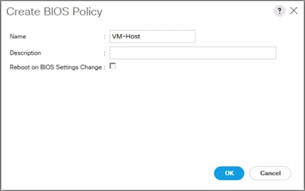
6. Select and right-click the newly created BIOS Policy.
7. Within the Main tab of the Policy:
a. Change CDN Control to enabled.
b. Change the Quiet Boot setting to disabled.
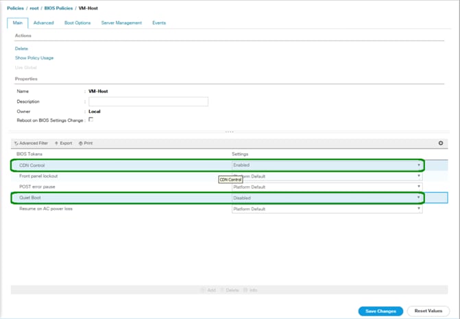
8. Click the Advanced tab, leaving the Processor tab selected within the Advanced tab.
9. Set the following within the Processor tab:
a. DRAM Clock Throttling -> Performance
b. Frequency Floor Override -> Enabled
c. Processor C State -> Disabled
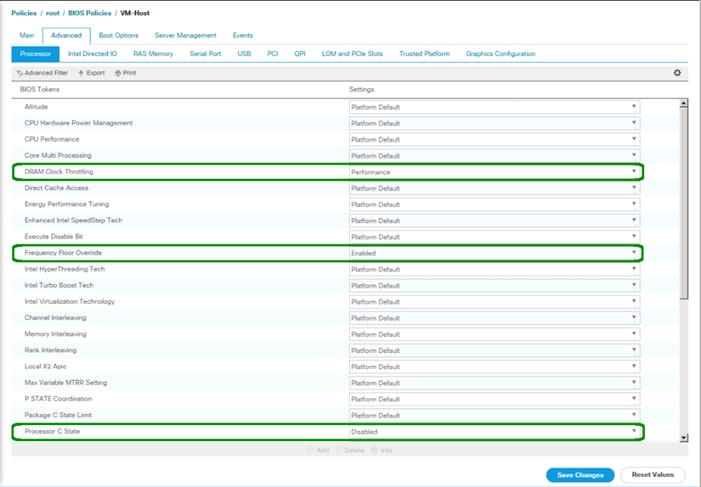
10. Scroll down to the remaining Processor options and select:
a. Processor C1E -> disabled
b. Processor C3 Report -> disabled
c. Processor C7 Report -> disabled
d. Energy Performance -> performance
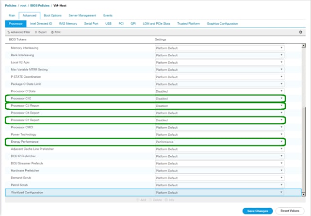
11. Click the RAS Memory tab and select:
a. LV DDR Mode -> performance-mode
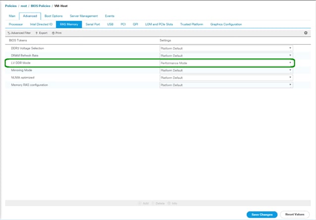
12. Click Save Changes.
13. Click OK.
Update the Default Maintenance Policy
To update the default Maintenance Policy, follow these steps:
1. In Cisco UCS Manager, click the Servers tab in the navigation pane.
2. Select Policies > root.
3. Select Maintenance Policies > default.
4. Change the Reboot Policy to User Ack.
5. (Optional: Click “On Next Boot” to delegate maintenance windows to server owners).
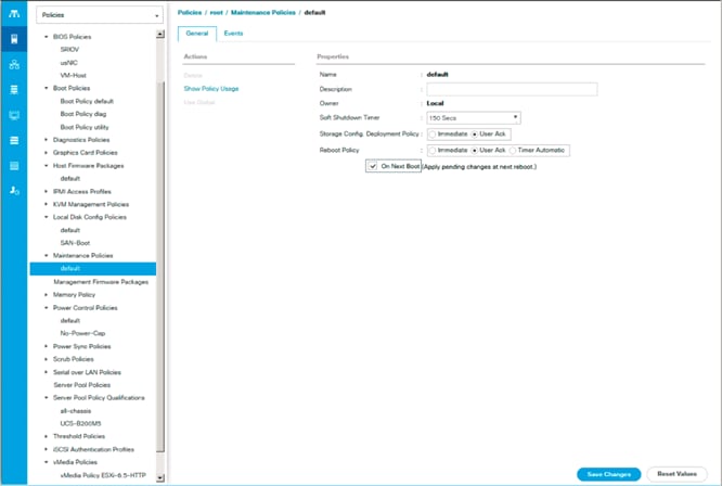
6. Click Save Changes.
7. Click OK to accept the change.
Create Local Disk Configuration Policy
A local disk configuration for the Cisco UCS environment is necessary if the servers in the environment do not have a local disk.
![]() This policy should not be used on servers that contain local disks.
This policy should not be used on servers that contain local disks.
To create a local disk configuration policy, follow these steps:
1. In Cisco UCS Manager, click the Servers tab in the navigation pane.
2. Select Policies > root.
3. Right-click Local Disk Config Policies.
4. Select Create Local Disk Configuration Policy.
5. Enter SAN-Boot as the local disk configuration policy name.
6. Change the mode to No Local Storage.
7. Click OK to create the local disk configuration policy.
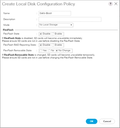
8. Click OK.
Create Power Control Policy
To create a power control policy for the Cisco UCS environment, follow these steps:
1. In Cisco UCS Manager, click the Servers tab in the navigation pane.
2. Select Policies > root.
3. Right-click Power Control Policies.
4. Select Create Power Control Policy.
5. Enter No-Power-Cap as the power control policy name.
6. Change the power capping setting to No Cap.
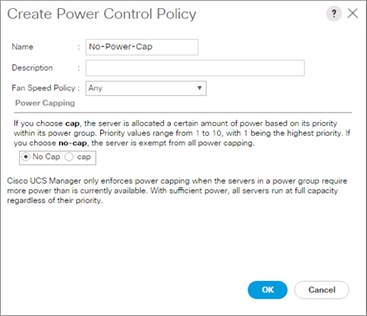
7. Click OK to create the power control policy.
8. Click OK.
Create Network Control Policy for Cisco Discovery Protocol and Link Layer Discovery Protocol
To create a network control policy that enables Cisco Discovery Protocol (CDP) and Link Layer Discovery Protocol (LLDP) on virtual network ports, follow these steps:
1. In Cisco UCS Manager, click the LAN tab in the navigation pane.
2. Select Policies > root.
3. Right-click Network Control Policies.
4. Select Create Network Control Policy.
5. Enter Enable_CDP_LLDP as the policy name.
6. For CDP, select the Enabled option.
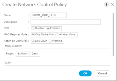
7. Scroll down within the policy creation window.
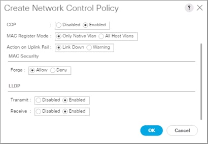
8. Select Enabled for both Transmit and Receive under the LLDP section.
9. Click OK to create the network control policy.
10. Click OK.
Configure Cisco UCS LAN Connectivity
Create Uplink Port Channels
To configure the necessary port channels out of the Cisco UCS environment, follow these steps:
1. In Cisco UCS Manager, click the LAN tab in the navigation pane.
![]() In this procedure, two port channels are created: one from fabric A to both Cisco Nexus switches and one from fabric B to both Cisco Nexus switches.
In this procedure, two port channels are created: one from fabric A to both Cisco Nexus switches and one from fabric B to both Cisco Nexus switches.
2. Under LAN > LAN Cloud, expand the Fabric A tree.
3. Right-click Port Channels.
4. Select Create Port Channel.
5. Enter a unique ID for the port channel, (147 in our example to correspond with the upstream Nexus ports being connected to).
6. With 15 selected, enter vPC-147-93180 as the name of the port channel.
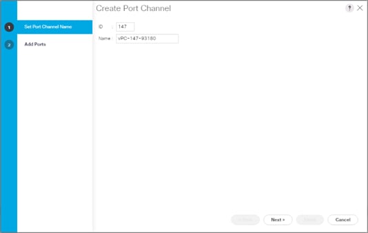
7. Click Next.
8. Select the following ports to be added to the port channel:
a. Slot ID 1 and port 47
b. Slot ID 1 and port 48
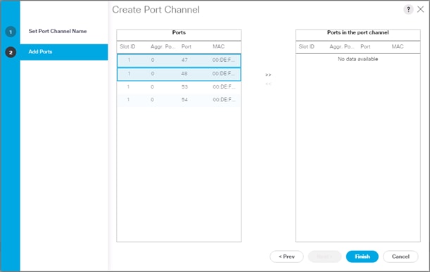
9. Click >> to add the ports to the port channel.
10. Click Finish to create the port channel.
11. Click OK.
12. In the navigation pane, under LAN > LAN Cloud, expand the fabric B tree.
13. Right-click Port Channels.
14. Select Create Port Channel.
15. Enter a unique ID for the port channel, (148 in our example to correspond with the upstream Nexus ports being connected to).
16. With 16 selected, enter vPC-148-93180 as the name of the port channel.
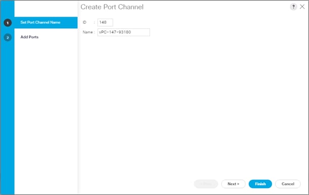
17. Click Next.
18. Select the following ports to be added to the port channel:
a. Slot ID 1 and port 47
b. Slot ID 1 and port 48

19. Click >> to add the ports to the port channel.
20. Click Finish to create the port channel.
21. Click OK.
Create VLANs
To configure the necessary virtual local area networks (VLANs) for the Cisco UCS environment, follow these steps:
1. In Cisco UCS Manager, click the LAN tab in the navigation pane.
![]() In this procedure, six unique VLANs are created. See Table 2 for a list of VLANs to be created.
In this procedure, six unique VLANs are created. See Table 2 for a list of VLANs to be created.
2. Select LAN > LAN Cloud.
3. Right-click VLANs.
4. Select Create VLANs.
5. Enter Native as the name of the VLAN to be used as the native VLAN.
6. Keep the Common/Global option selected for the scope of the VLAN.
7. Enter the native VLAN ID.
8. Keep the Sharing Type as None.
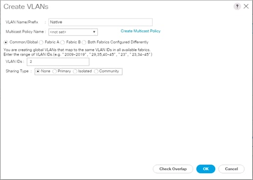
9. Click OK and then click OK again.
10. Expand the list of VLANs in the navigation pane, right-click the newly created Native-VLAN and select Set as Native VLAN.
11. Click Yes and then click OK.
12. Right-click VLANs.
13. Select Create VLANs
14. Enter Site-Infra as the name of the VLAN to be used for management traffic.
15. Keep the Common/Global option selected for the scope of the VLAN.
16. Enter the In-Band management VLAN ID.
17. Keep the Sharing Type as None.
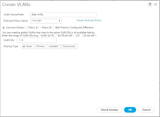
18. Click OK and then click OK again.
19. Right-click VLANs.
20. Select Create VLANs.
21. Enter vMotion as the name of the VLAN to be used for vMotion.
22. Keep the Common/Global option selected for the scope of the VLAN.
23. Enter the vMotion VLAN ID.
24. Keep the Sharing Type as None.

25. Click OK and then click OK again.
26. Repeat as needed for any additional VLANs created on the upstream Nexus switches.
Create vNIC Templates
To create the multiple virtual network interface card (vNIC) templates for the Cisco UCS environment, follow the steps in this section.
Create Management vNICs
For the vNIC_Mgmt_A Template, follow these steps:
1. In Cisco UCS Manager, click the LAN tab in the navigation pane.
2. Select Policies > root.
3. Right-click vNIC Templates.
4. Select Create vNIC Template.
5. Enter vNIC_Mgmt_A as the vNIC template name.
6. Keep Fabric A selected.
7. Select Primary Template for the Redundancy Type.
8. Leave Peer Redundancy Template as <not set>
![]() Redundancy Type and specification of Redundancy Template are configuration options to later allow changes to the Primary Template to automatically adjust onto the Secondary Template.
Redundancy Type and specification of Redundancy Template are configuration options to later allow changes to the Primary Template to automatically adjust onto the Secondary Template.
9. Under Target, make sure that the VM checkbox is not selected.
10. Select Updating Template as the Template Type.
11. Under VLANs, select the checkboxes for Site-Infra, Common, Host-Mgmt, vMotion, and Native VLANs.
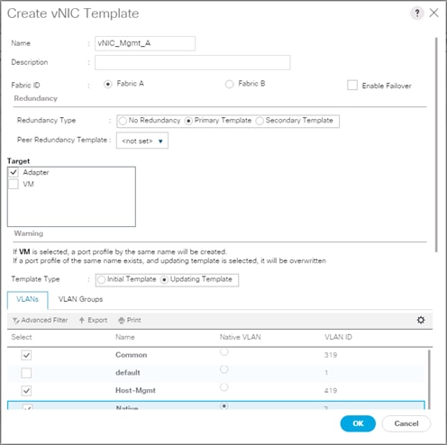
12. Set Native as the native VLAN.
13. Leave vNIC Name selected for the CDN Source.
14. For MTU, enter 9000.
15. In the MAC Pool list, select MAC_Pool_A.
16. In the Network Control Policy list, select Enable_CDP.
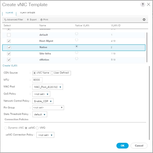
17. Click OK to create the vNIC template.
18. Click OK.
For the vNIC_Mgmt_B Template, follow these steps:
1. In the navigation pane, select the LAN tab.
2. Select Policies > root.
3. Right-click vNIC Templates.
4. Select Create vNIC Template
5. Enter vNIC_Mgmt_B as the vNIC template name.
6. Select Fabric B.
7. Select Secondary Template for Redundancy Type.
8. For the Peer Redundancy Template drop-down, select vNIC_Mgmt_A.
![]() With Peer Redundancy Template selected, Template Type, VLANs, CDN Source, MTU, and Network Control Policy are all pulled from the Primary Template.
With Peer Redundancy Template selected, Template Type, VLANs, CDN Source, MTU, and Network Control Policy are all pulled from the Primary Template.
9. Under Target, make sure the VM checkbox is not selected.
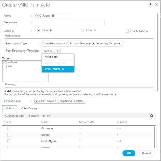
10. In the MAC Pool list, select MAC_Pool_B.
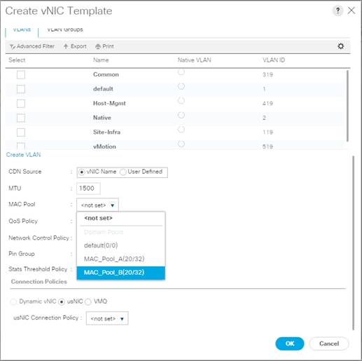
11. Click OK to create the vNIC template.
12. Click OK.
Create vDS Application vNICs
For the vNIC_vDS_A Template, follow these steps:
1. In Cisco UCS Manager, click the LAN tab in the navigation pane.
2. Select Policies > root.
3. Right-click vNIC Templates.
4. Select Create vNIC Template.
5. Enter vNIC_vDS_A as the vNIC template name.
6. Keep Fabric A selected.
7. Leave No Redundancy selected for the Redundancy Type.
8. Under Target, make sure that the VM checkbox is not selected.
9. Select Updating Template as the Template Type.
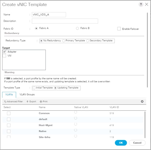
10. For MTU, enter 9000.
11. In the MAC Pool list, select MAC_Pool_A.
12. In the Network Control Policy list, select Enable_LLDP.
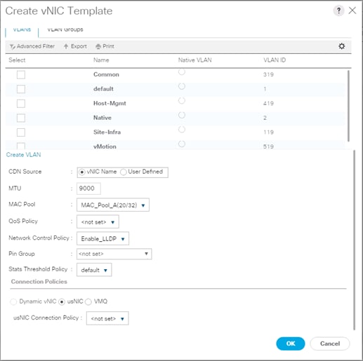
13. Click OK to create the vNIC template.
14. Click OK.
For the vNIC_vDS_B Template, follow these steps:
1. In the navigation pane, select the LAN tab.
2. Select Policies > root.
3. Right-click vNIC Templates.
4. Select Create vNIC Template
5. Enter vNIC_vDS_B as the vNIC template name.
6. Select Fabric B.
7. Leave No Redundancy selected for the Redundancy Type.
![]() Peer Redundancy has not been configured between the two vDS vNIC Templates because with the vDS VMM implementation configured later will update both vNIC Templates using the UCS integration.
Peer Redundancy has not been configured between the two vDS vNIC Templates because with the vDS VMM implementation configured later will update both vNIC Templates using the UCS integration.
8. Under Target, make sure the VM checkbox is not selected.

9. For MTU, enter 9000.
10. In the MAC Pool list, select MAC_Pool_B.
11. In the Network Control Policy list, select Enable_LLDP.

12. Click OK to create the vNIC template.
13. Click OK.
Set Jumbo Frames in Cisco UCS Fabric
![]() These steps are unnecessary for the Cisco UCS 6454 FIs as they default to jumbo frames.
These steps are unnecessary for the Cisco UCS 6454 FIs as they default to jumbo frames.
To configure jumbo frames and enable quality of service in the Cisco UCS fabric, follow these steps:
1. In Cisco UCS Manager, click the LAN tab in the navigation pane.
2. Select LAN > LAN Cloud > QoS System Class.
3. In the right pane, click the General tab.
4. On the Best Effort row, enter 9216 in the box under the MTU column.
5. Click Save Changes in the bottom of the window.
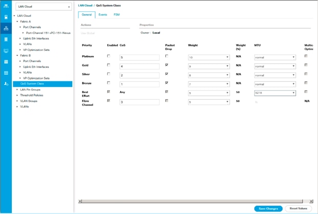
6. Click OK
Create LAN Connectivity Policy
To configure the necessary Fibre Channel Infrastructure LAN Connectivity Policy, follow these steps:
1. In Cisco UCS Manager, click the LAN tab in the navigation pane.
2. Select LAN > Policies > root.
3. Right-click LAN Connectivity Policies.
4. Select Create LAN Connectivity Policy.
5. Enter FC-LAN-Policy as the name of the policy.
6. Click the upper Add button to add a vNIC.
7. In the Create vNIC dialog box, enter 00-Mgmt-A as the name of the vNIC.
![]() The numeric prefix of “00-“ and subsequent increments on the later vNICs are used in the vNIC naming to force the device ordering through Consistent Device Naming (CDN). Without this, some operating systems might not respect the device ordering that is set within Cisco UCS.
The numeric prefix of “00-“ and subsequent increments on the later vNICs are used in the vNIC naming to force the device ordering through Consistent Device Naming (CDN). Without this, some operating systems might not respect the device ordering that is set within Cisco UCS.
8. Select the Use vNIC Template checkbox.
9. In the vNIC Template list, select vNIC_Mgmt_A.
10. In the Adapter Policy list, select VMWare.
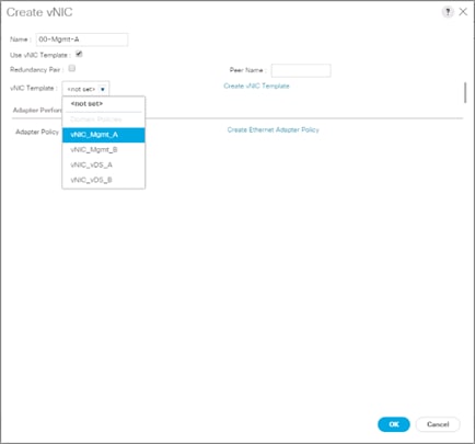
11. Click OK to add this vNIC to the policy.
12. Click the upper Add button to add another vNIC to the policy.
13. In the Create vNIC box, enter 01-Mgmt-B as the name of the vNIC.
14. Select the Use vNIC Template checkbox.
15. In the vNIC Template list, select vNIC_Mgmt_B.
16. In the Adapter Policy list, select VMWare.
17. Click OK to add the vNIC to the policy.
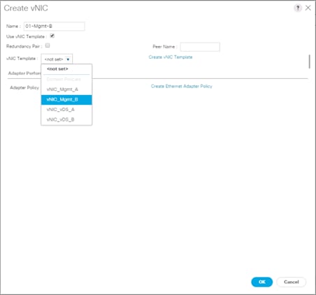
18. Click the upper Add button to add a vNIC.
19. In the Create vNIC dialog box, enter 02-vDS-A as the name of the vNIC.
20. Select the Use vNIC Template checkbox.
21. In the vNIC Template list, select vNIC_vDS_A.
22. In the Adapter Policy list, select VMWare.
23. Click OK to add this vNIC to the policy.
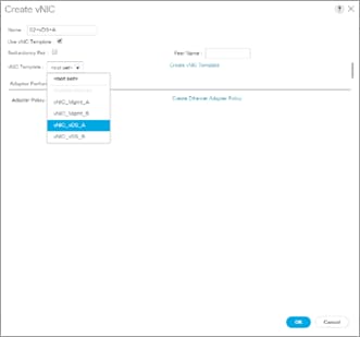
24. Click the upper Add button to add a vNIC to the policy.
25. In the Create vNIC dialog box, enter 03-App-B as the name of the vNIC.
26. Select the Use vNIC Template checkbox.
27. In the vNIC Template list, select vNIC_App_B.
28. In the Adapter Policy list, select VMWare.
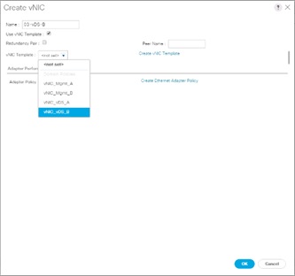
29. Click OK to add this vNIC to the policy.
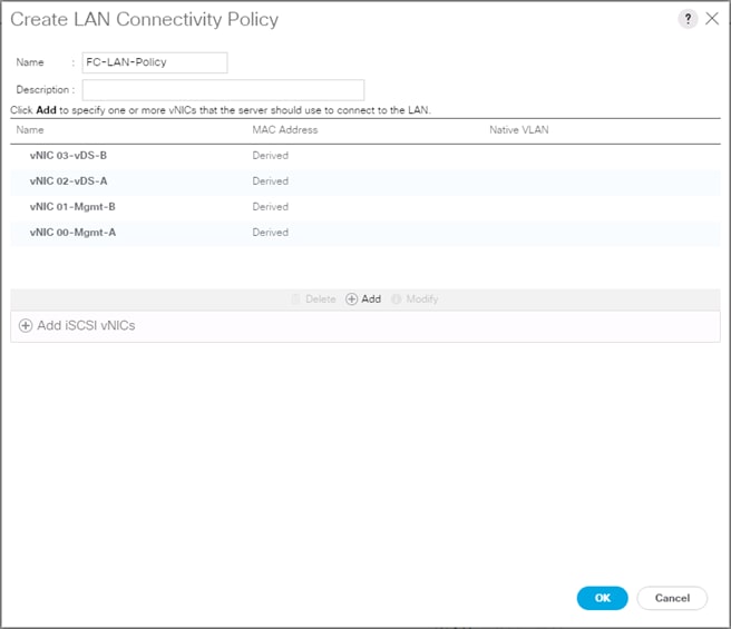
30. Click OK to create the LAN Connectivity Policy.
31. Click OK.
Configure FC SAN Connectivity
These Fibre Channel configuration steps will enable the provisioning of volumes to be used as datastores by the vSphere hosts, and the creation of Cisco UCS Service Profiles that will be configured to boot from Fibre Channel LUNs.
Configure Unified Ports
The Cisco UCS 6454 Fabric Interconnects will have a slider mechanism within the Cisco UCS Manager GUI interface that will control the first 8 ports starting from the first port, allowing the selection of the first 4, or all 8 of the unified ports. The Cisco UCS 6332-16UP has a similar mechanism controlling the first 16 ports starting from the first port, configuring in increments of the first 6, 12, or all 16 of the unified ports.
To enable the fibre channel ports, follow these steps:
1. In Cisco UCS Manager, click the Equipment tab in the navigation pane.
2. Select Equipment > Fabric Interconnects > Fabric Interconnect A (primary)
3. Select Configure Unified Ports.
4. Click Yes on the pop-up window warning that changes to the fixed module will require a reboot of the fabric interconnect and changes to the expansion module will require a reboot of that module.
5. Within the Configured Fixed Ports pop-up window move the gray slider bar from the left to the right to select either the first 4 or all 8 of the ports to be set as FC Uplinks.
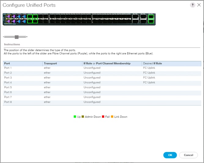
![]() For Cisco UCS 6332-16UP, these fixed ports will be in groups of 6, 12, or 16 ports to be set as FC Uplinks.
For Cisco UCS 6332-16UP, these fixed ports will be in groups of 6, 12, or 16 ports to be set as FC Uplinks.
6. Click OK to continue
7. Click Yes within the subsequent warning pop-up and wait for reboot to complete.
8. Log back into UCSM when available.
9. Select Equipment > Fabric Interconnects > Fabric Interconnect B (primary)
10. Select Configure Unified Ports.
11. Click Yes on the pop-up window warning that changes to the fixed module will require a reboot of the fabric interconnect and changes to the expansion module will require a reboot of that module.
12. Within the Configured Fixed Ports pop-up window move the gray slider bar from the left to the right to select the same 4 or 8 ports to be set as FC Uplinks.
13. Click OK to continue
14. Click Yes within the subsequent warning pop-up and wait for reboot to complete.
Create VSANs
To configure the necessary virtual storage area networks (VSANs) for the Cisco UCS environment, follow these steps:
1. In Cisco UCS Manager, click the SAN tab in the navigation pane.
![]() In this procedure, two VSANs are created.
In this procedure, two VSANs are created.
2. Select SAN > SAN Cloud.
3. Right-click VSANs.
4. Select Create VSAN.
5. Enter VSAN_A as the name of the VSAN to be used for Fabric A
6. Leave Disabled selected for FC Zoning.
7. Select Fabric A.
8. Enter a unique VSAN ID and a corresponding FCoE VLAN ID. It is recommended use the same ID for both parameters and to use something other than 1.
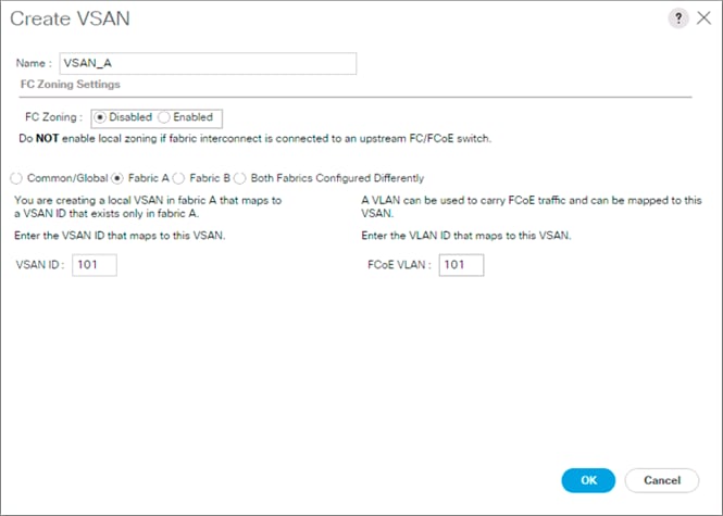
9. Click OK and then click OK again.
10. Under SAN Cloud, right-click VSANs.
11. Select Create VSAN.
12. Enter VSAN_B as the name of the VSAN to be used for Fabric B.
13. Leave Disabled selected for FC Zoning.
14. Select Fabric B.
15. Enter a unique VSAN ID and a corresponding FCoE VLAN ID. It is recommended use the same ID for both parameters and to use something other than 1.

16. Click OK and then click OK again.
Create FC Port Channels
To configure the necessary port channels for the Cisco UCS environment, follow these steps:
Fabric-A
1. In the navigation pane under SAN > SAN Cloud expand the Fabric A tree.
2. Right-click FC Port Channels.
3. Select Create FC Port Channel.
4. Enter 1 for the ID and Po1 for the Port Channel name.
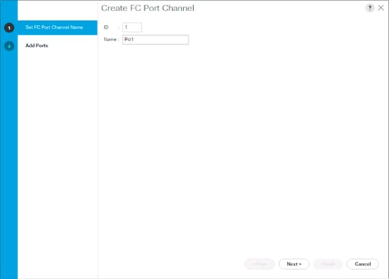
5. Click Next.
6. Set the Port Channel Admin Speed to 32Gbps, or appropriate for the environment, choose connected ports and click >> to add the ports to the port channel.

7. Click Finish.
8. Click OK.
9. Select the newly created Port-Channel.
10. Under the VSAN drop-down list for Port-Channel 1, select VSAN_A 101.
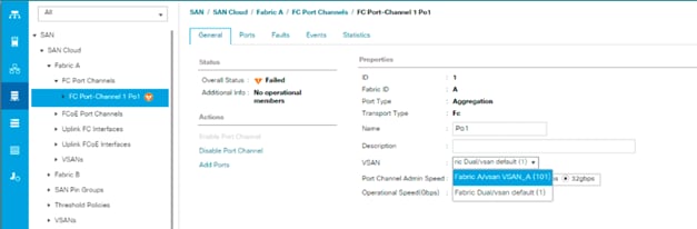
11. Click Save Changes and then click OK.
Fabric-B
1. In the navigation pane, under SAN > SAN Cloud, expand the Fabric B tree.
2. Right-click FC Port Channels.
3. Select Create Port Channel.
4. Enter 2 for the ID and Po2 for the Port Channel name.
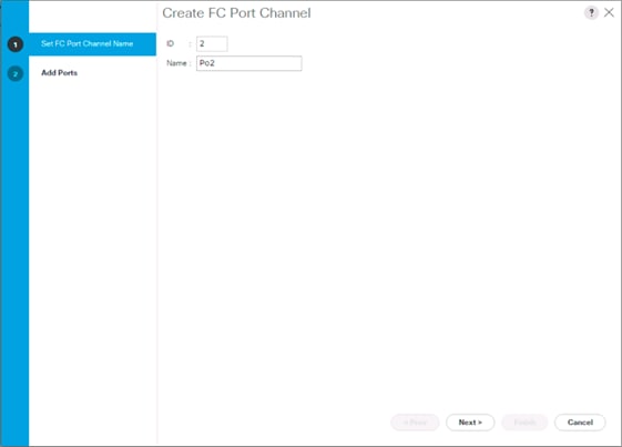
5. Click Next
6. Set the Port Channel Admin Speed to 32Gbps, or appropriate for the environment, choose connected ports and click >> to add the ports to the port channel.
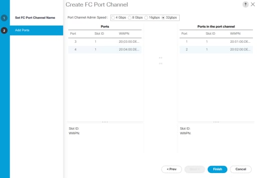
7. Click Finish.
8. Click OK.
9. Select the newly created Port-Channel
10. Under the VSAN drop-down list for Port-Channel 2, select VSAN_B 102.
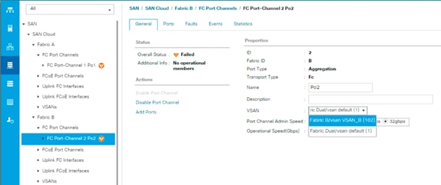
11. Click Save Changes and then click OK.
![]() If the UCS FC ports show as error disabled at this point due to a timing of operations, a disable and subsequent enable of the error disabled port will be needed.
If the UCS FC ports show as error disabled at this point due to a timing of operations, a disable and subsequent enable of the error disabled port will be needed.
Create vHBA Templates
To create the necessary virtual host bus adapter (vHBA) templates for the Cisco UCS environment, follow these steps:
1. In Cisco UCS Manager, click the SAN tab in the navigation pane.
2. Select Policies > root.
3. Right-click vHBA Templates.
4. Select Create vHBA Template.
5. Enter vHBA_Template_A as the vHBA template name.
6. Keep Fabric A selected.
7. Leave Redundancy Type as No Redundancy.
8. Select VSAN_A.
9. Leave Initial Template as the Template Type.
10. Select WWPN_Pool_A as the WWPN Pool.
11. Click OK to create the vHBA template.

12. Click OK.
13. Right-click vHBA Templates.
14. Select Create vHBA Template.
15. Enter vHBA_Template_B as the vHBA template name.
16. Select Fabric B as the Fabric ID.
17. Leave Redundancy Type as No Redundancy.
18. Select VSAN_B.
19. Leave Initial Template as the Template Type.
20. Select WWPN_Pool_B as the WWPN Pool.
21. Click OK to create the vHBA template.
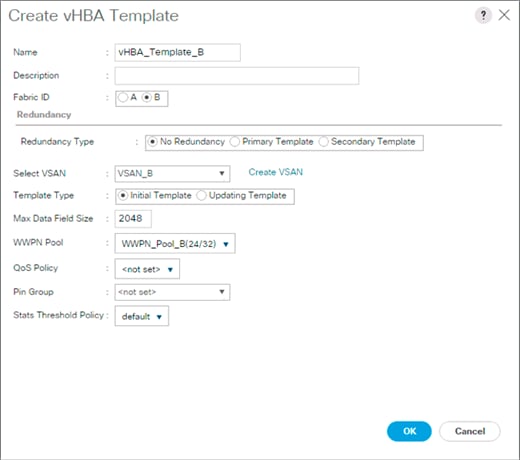
22. Click OK.
Create SAN Connectivity Policy
To configure the necessary Infrastructure SAN Connectivity Policy, follow these steps:
1. In Cisco UCS Manager, click the SAN tab in the navigation pane.
2. Select SAN > Policies > root.
3. Right-click SAN Connectivity Policies.
4. Select Create SAN Connectivity Policy.
5. Enter Infra-SAN-Policy as the name of the policy.
6. Select the previously created WWNN_Pool for the WWNN Assignment.
7. Click the Add button at the bottom to add a vHBA.
8. In the Create vHBA dialog box, enter Fabric-A as the name of the vHBA.
9. Select the Use vHBA Template checkbox.
10. Leave Redundancy Pair unselected.
11. In the vHBA Template list, select vHBA_Template_A.
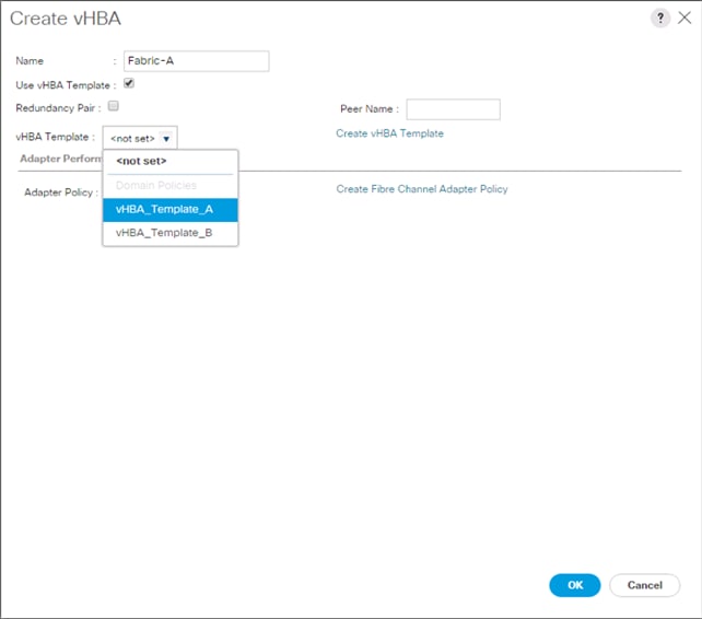
12. In the Adapter Policy list, select VMWare.
13. Click OK.
14. Click the Add button at the bottom to add a second vHBA.
15. In the Create vHBA dialog box, enter Fabric-B as the name of the vHBA.
16. Select the Use vHBA Template checkbox.
17. Leave Redundancy Pair unselected.
18. In the vHBA Template list, select vHBA_Template_B.
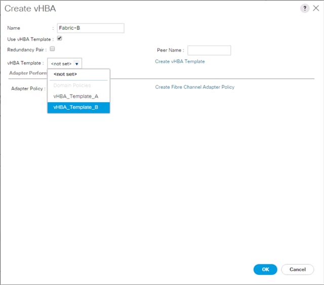
19. In the Adapter Policy list, select VMWare.
20. Click OK.
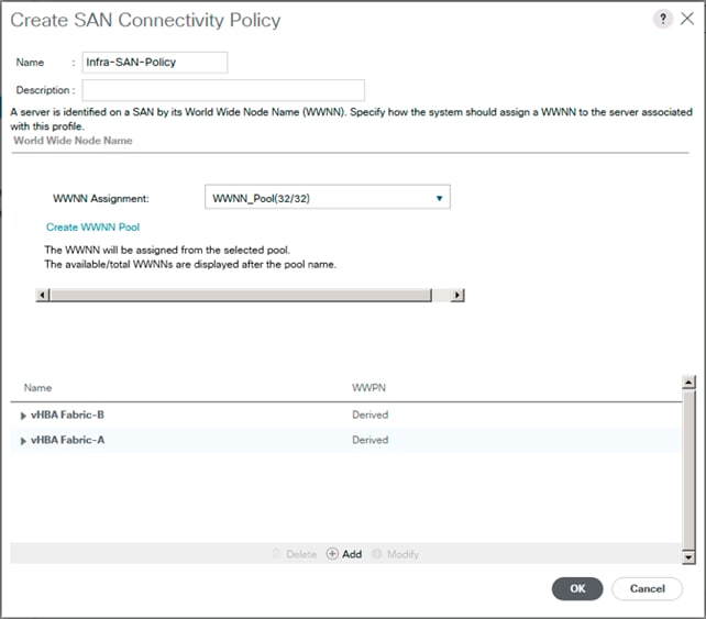
21. Click OK to create the SAN Connectivity Policy.
22. Click OK to confirm creation.
Create Boot Policy
The VSP G370 target WWPN will need to be collected at this point to provide the Cisco UCS Boot Policy
These target WWPN can be collected directly from the VSP but running the show flogi database command from each MDS will be fairly quick provided there is clear identification of the port cabling from the VSP ports to the MDS ports.
Table 23 VSP G370 to MDS Port Information Carried Forward
| Local Device |
Local Port |
Connection |
Remote Device |
Remote Port |
| Hitachi VSP G370
|
CL 1-A |
32Gb FC |
Cisco MDS 9706 A |
FC 1/11 |
| CL 2-B |
32Gb FC |
Cisco MDS 9706 A |
FC 1/12 |
|
| CL 3-B |
32Gb FC |
Cisco MDS 9706 B |
FC 1/11 |
|
| CL 4-A |
32Gb FC |
Cisco MDS 9706 B |
FC 1/12 |
Using the table, it is possible to get the expected local port (VSP) to remote port (MDS) values. With this information, the WWPN can be pulled out of the flogi to port connections on the respective MDS.
Running the sh flogi database command on MDS A:
AA19-9706-1# sh flogi database
--------------------------------------------------------------------------------
INTERFACE VSAN FCID PORT NAME NODE NAME
--------------------------------------------------------------------------------
fc1/11 101 0xbc01a0 50:06:0e:80:12:c9:9a:00 50:06:0e:80:12:c9:9a:00
fc1/12 101 0xbc0180 50:06:0e:80:12:c9:9a:11 50:06:0e:80:12:c9:9a:11
Running the sh flogi database command on MDS B:
aa19-9706-2# sh flogi database
--------------------------------------------------------------------------------
INTERFACE VSAN FCID PORT NAME NODE NAME
fc1/11 102 0x2801e0 50:06:0e:80:12:c9:9a:21 50:06:0e:80:12:c9:9a:21
fc1/12 102 0x280180 50:06:0e:80:12:c9:9a:30 50:06:0e:80:12:c9:9a:30
Find the appropriate VSP G370 local ports for each fabric and record the values to be used for Primary and Secondary Boot Targets. In the example lab environment flogi output, the MDS Interface (Remote Port) values in the previous table for this fabric have been cross referenced, and the WWPN(Port Name) for these interfaces are recorded.
Table 24 Fabric A Boot Targets for the VSP G370
|
|
MDS Interface |
Example Local Port |
Target Role |
WWN/WWPN Example Environment (Port Name) |
WWN/WWPN Customer Environment |
| VSP G370 Controller 1 |
1/11 |
CL 1-A |
Primary Boot/ VMFS |
50:06:0e:80:12:c9:9a:00 |
|
| VSP G370 Controller 2 |
1/12 |
CL 2-B |
Secondary Boot/ VMFS |
50:06:0e:80:12:c9:9a:11 |
|
Repeat these steps for the VSP G370 Fabric B Primary and Secondary Boot Targets:
Table 25 Fabric B Boot Targets for the VSP G370
|
|
MDS Interface |
Example Local Port |
Target Role |
WWN/WWPN Example Environment |
WWN/WWPN Customer Environment |
| VSP G370 Controller 1 |
1/11 |
CL 3-B |
Primary Boot/ VMFS |
50:06:0e:80:12:c9:9a:21 |
|
| VSP G370 Controller 2 |
1/12 |
CL 4-A |
Secondary Boot/ VMFS |
50:06:0e:80:12:c9:9a:30 |
|
To create boot policies for the Cisco UCS environment, follow these steps:
1. In Cisco UCS Manager, click the Servers tab in the navigation pane.
2. Select Policies > root.
3. Right-click Boot Policies.
4. Select Create Boot Policy.
5. Enter Boot-FC-G370-A as the name of the boot policy.
6. Optional: Enter a description for the boot policy.
![]() Do not select the Reboot on Boot Order Change checkbox.
Do not select the Reboot on Boot Order Change checkbox.
7. Expand the Local Devices drop-down menu and select Add Remote CD/DVD.
8. Expand the vHBAs drop-down menu and select Add SAN Boot.
9. In the Add SAN Boot dialog box, enter Fabric-A in the vHBA field.
10. Confirm that Primary is selected for the Type option.
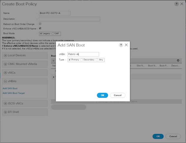
11. Click OK to add the SAN boot initiator.
12. From the vHBA drop-down menu, select Add SAN Boot Target.
13. Leave 0 as the value for Boot Target LUN.
14. Enter the WWPN for Controller1 (CL 1A) recorded in Table 24 .
15. Select Primary for the SAN boot target type.
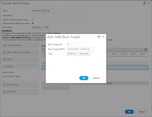
16. Click OK to add the SAN boot target.
17. From the vHBA drop-down menu, select Add SAN Boot Target.
18. Leave 0 as the value for Boot Target LUN.
19. Enter the WWPN for Controller2 (CL 2B) recorded in Table 25
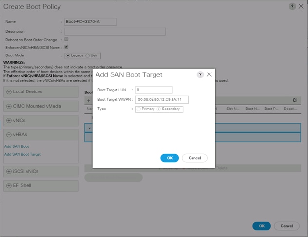
20. Click OK to add the SAN boot target.
21. From the vHBA drop-down list, select Add SAN Boot.
22. In the Add SAN Boot dialog box, enter Fabric-B in the vHBA box.
![]() The SAN boot type should automatically be set to Secondary and the Type option should be unavailable.
The SAN boot type should automatically be set to Secondary and the Type option should be unavailable.
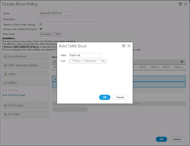
23. Click OK to add the SAN boot initiator.
24. From the vHBA drop-down menu, select Add SAN Boot Target.
25. Leave 0 as the value for Boot Target LUN.
26. Enter the WWPN for Controller1 (CL 3B) recorded in Table 25
27. Select Primary for the SAN boot target type.
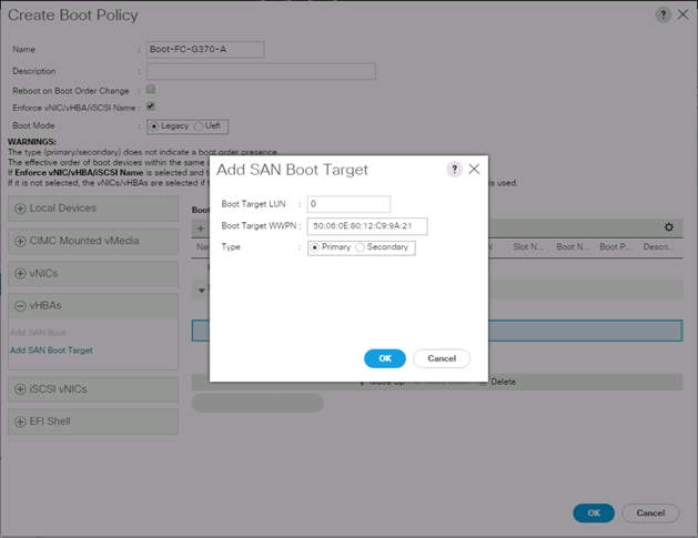
28. Click OK to add the SAN boot target.
29. From the vHBA drop-down menu, select Add SAN Boot Target.
30. Enter 0 as the value for Boot Target LUN.
31. Enter the WWPN for Controller2 (CL 4A) recorded in Table 25
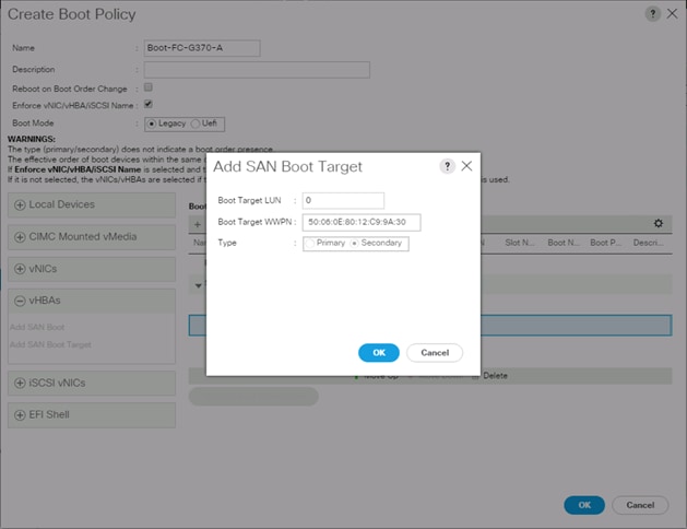
32. Click OK to add the SAN boot target.
33. Expand CIMC Mounted vMedia and select Add CIMC Mounted CD/DVD.
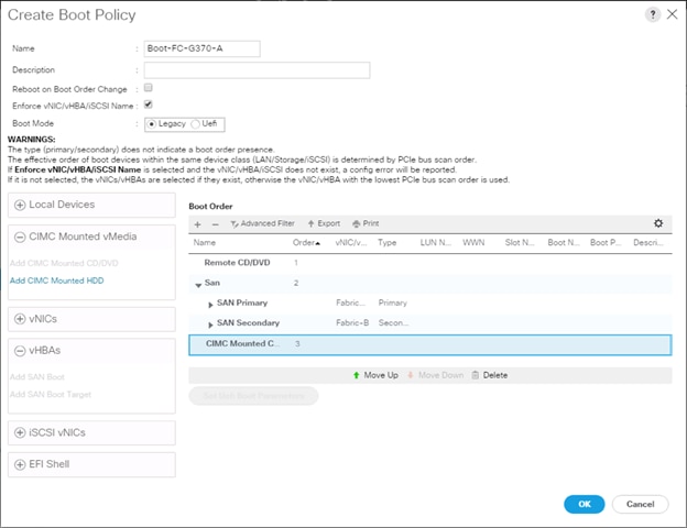
34. Click OK, then click OK again to create the boot policy.
Create Service Profile Template
In this procedure, one service profile template for Infrastructure ESXi hosts is created for fabric A boot.
To create the service profile template, follow these steps:
1. In Cisco UCS Manager, click the Servers tab in the navigation pane.
2. Select Service Profile Templates > root.
3. Right-click root.
4. Select Create Service Profile Template to open the Create Service Profile Template wizard.
5. Enter VSI-FC-G370-A as the name of the service profile template. This service profile template is configured to boot from VSP G370 controller 1 on fabric A.
6. Select the “Updating Template” option.
7. Under UUID, select UUID_Pool as the UUID pool.
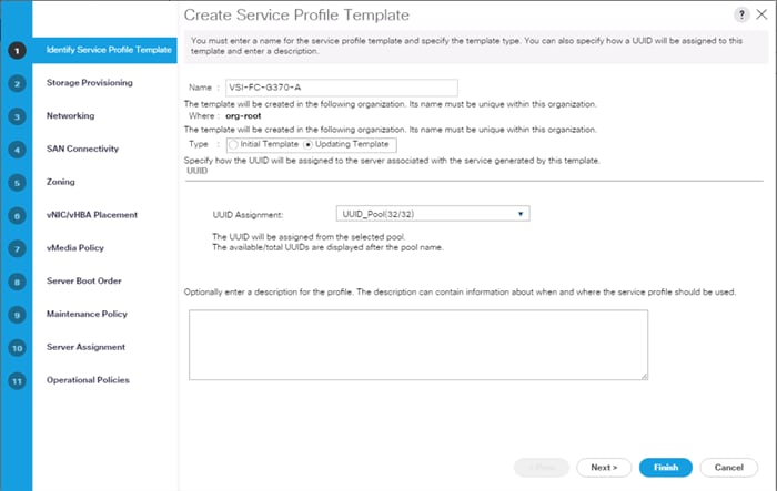
8. Click Next.
Configure Storage Provisioning
To configure the storage provisioning, follow these steps:
1. If you have servers with no physical disks, click the Local Disk Configuration Policy tab and select the SAN-Boot Local Storage Policy. Otherwise, select the default Local Storage Policy.
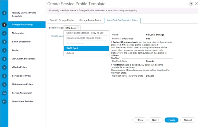
2. Click Next.
Configure Networking Options
To configure the network options, follow these steps:
1. Keep the default setting for Dynamic vNIC Connection Policy.
2. Select the “Use Connectivity Policy” option to configure the LAN connectivity.
3. Select FC-LAN-Policy from the LAN Connectivity Policy drop-down list.
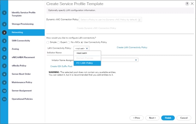
4. Click Next.
Configure Storage Options
To configure the storage options, follow these steps:
1. Select the Use Connectivity Policy option for the “How would you like to configure SAN connectivity?” field.
2. Pick the Infra-SAN-Policy option from the SAN Connectivity Policy drop-down list.
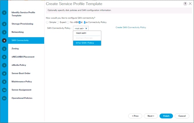
3. Click Next.
Configure Zoning Options
1. Leave Zoning configuration unspecified and click Next.
Configure vNIC/HBA Placement
1. In the “Select Placement” list, leave the placement policy as “Let System Perform Placement.”
2. Click Next.
Configure vMedia Policy
1. Do not select a vMedia Policy.
2. Click Next.
Configure Server Boot Order
1. Select Boot-FC-G370-A for Boot Policy.
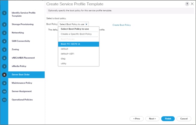
2. Click Next to continue to the next section.
Configure Maintenance Policy
1. Change the Maintenance Policy to default.
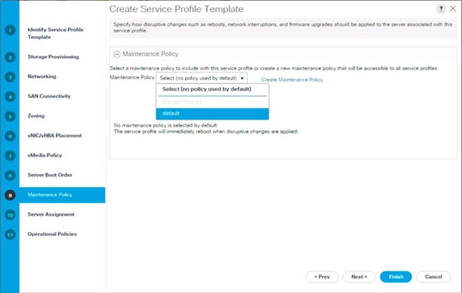
2. Click Next.
Configure Server Assignment
To configure server assignment, follow these steps:
1. In the Pool Assignment list, select Infra_Pool.
2. Optional: Select a Server Pool Qualification policy.
3. Select Up as the power state to be applied when the profile is associated with the server.
4. Optional: Select “UCS-B200M5” for the Server Pool Qualification.
![]() Skip Firmware Management since it will use the default from the Host Firmware list.
Skip Firmware Management since it will use the default from the Host Firmware list.
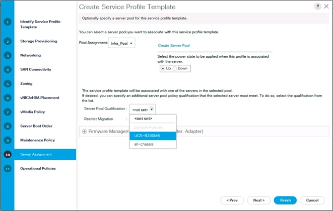
5. Click Next.
Configure Operational Policies
To configure the operational policies, follow these steps:
1. In the BIOS Policy list, select VM-Host.
2. Expand Power Control Policy Configuration and select No-Power-Cap in the Power Control Policy list.
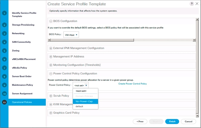
3. Click Finish to create the service profile template.
4. Click OK in the confirmation message.
Create vMedia Service Profile Template
If the optional vMedia Policy is being used, a clone of the service profile template created above will be made to reference this vMedia Policy in these steps. The clone of the service profile template will have the vMedia Policy configured for it, and service profiles created from it, will be unbound and re-associated to the original service profile template after ESXi installation.
To create a clone of the VSI-FC-G370-A service profile template, and associate the vMedia Policy to it, follow these steps:
1. Connect to Cisco UCS Manager, click Servers.
2. Select Service Profile Templates > root > Service Template VSI-FC-G370-A.
3. Right-click Service Template VM-Host-FC-A and select Create a Clone.
4. Name the clone VSI-FC-G370-A-vM and click OK.
5. Select Service Template VSI-FC-G370-A-vM.
6. In the right pane, select the vMedia Policy tab.
7. Under Actions, select Modify vMedia Policy.
8. Using the drop-down, select the ESXi-6.7U2-HTTP vMedia Policy.
9. Click OK then OK again to complete modifying the Service Profile Template.
Create Service Profiles
To create service profiles from the service profile template, follow these steps:
1. Connect to the UCS 6454 Fabric Interconnect UCS Manager, click the Servers tab in the navigation pane.
2. Select Service Profile Templates > root > Service Template VSI-FC-G370-A-vM.
3. Right-click VSI-FC-G370-A-vM and select Create Service Profiles from Template.
4. Enter VSI-G370-0 as the service profile prefix.
5. Leave 1 as “Name Suffix Starting Number.”
6. Leave 2 as the “Number of Instances.”
7. Click OK to create the service profiles.
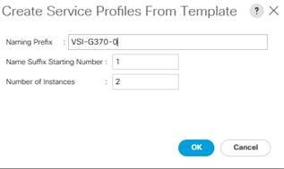
8. Click OK in the confirmation message to provision two Service Profiles.
![]() When VMware ESXi 6.7 U2 has been installed on the hosts, the host Service Profiles can be unbound from the VM-Host-FC-A-vM and rebound to the VM-Host-FC-A Service Profile Template to remove the vMedia mapping from the host, to prevent issues at boot time if the HTTP source for the ESXi ISO is somehow not available.
When VMware ESXi 6.7 U2 has been installed on the hosts, the host Service Profiles can be unbound from the VM-Host-FC-A-vM and rebound to the VM-Host-FC-A Service Profile Template to remove the vMedia mapping from the host, to prevent issues at boot time if the HTTP source for the ESXi ISO is somehow not available.
Collect UCS Host vHBA Information for Zoning
The VSP Targets that will be used were collected from the flogi database of each MDS fabric. This is not a clear option for the UCS Server host Initiators as each Initiator WWPN will show up within the configured port-channel of the fabric without any specifics of origin that came from the MDS interface ports used to identify the VSP Targets. UCSM will be used to collect the vHBA WWPNs used as the Initiators for the provisioned Service Profiles.
To collect UCS host vHBA information for zoning, follow these steps:
1. To collect the WWPNs, follow these steps with UCSM:
2. Click the SAN icon from the Navigation pane.
3. Select Pools from the drop-down.
4. Expand WWPN Pools and select the WWPN_Pool_A.
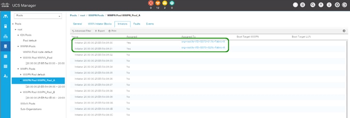
5. Identify the Fabric A Initiators assigned to the provisioned Service Profiles and add them to Table 26 .
Table 26 Fabric A G370 Service Profile Initiators
|
|
WWN/WWPN Example Environment (Port Name) |
WWN/WWPN Customer Environment |
| VSI-G370-01 |
20:00:00:25:B5:54:0A:00 |
|
| VSI-G370-02 |
20:00:00:25:B5:54:0A:01 |
|
6. Select WWPN_Pool_B.
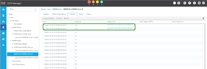
7. Identify the Fabric B Initiators assigned to the provisioned Service Profiles and add them to Table 27 .
Table 27 Fabric B G370 Service Profile Initiators
|
|
WWPN Example Environment (Port Name) |
WWN/WWPN Customer Environment |
| VSI-G370-01 |
20:00:00:25:B5:54:0B:00 |
|
| VSI-G370-02 |
20:00:00:25:B5:54:0B:01 |
|
![]() WWPN assignment is set to be sequential, so in most cases it can be extrapolated at initial provisioning based on WWPN Pool Suffix used, but confirmation is recommended.
WWPN assignment is set to be sequential, so in most cases it can be extrapolated at initial provisioning based on WWPN Pool Suffix used, but confirmation is recommended.
The Cisco MDS zoning used to connect the Cisco UCS and the Hitachi VSP will be configured using DCNM, which was deployed on resources independent of the Adaptive Solutions for CI data center. Deployment of DCNM is not explained in this document, however instructions can be found here:
If DCNM is not used in the customer environment, this section should be skipped and you should follow the information explained in section Appendix: MDS Device Alias and Zoning through CLI.
Connect to DCNM and Registering Switches
Registering of the Nexus switches is optional but will provide enhanced port visibility as well as the option to gather performance monitoring of the Ethernet traffic. The MDS switches will need to be registered to be able to implement the device alias creation and zoning shown below.
To register the switches, follow these steps:
1. Log into the DCNM installation with the admin account or provisioned account with appropriate credentials:
2. Provide LAN switch credentials from the initial dialogue if prompted and click Yes.
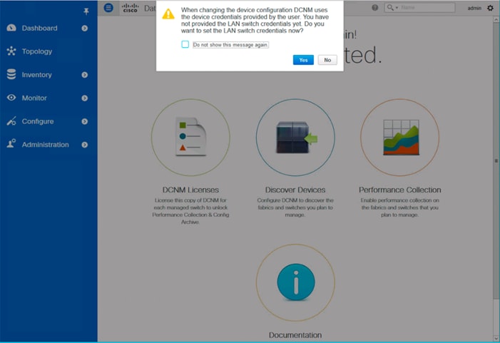
3. If not prompted, add credentials within Administration -> Credentials Management -> LAN Credentials.
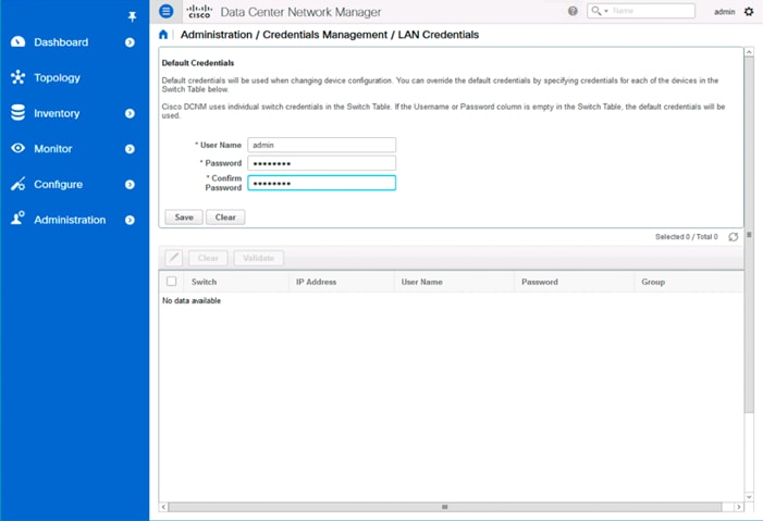
4. Click Save.
5. Click OK.
6. Add the MDS into DCNM by selecting Inventory -> Discovery -> SAN Switches.
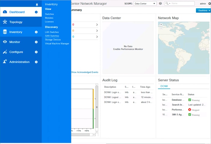
7. Click the + icon on the top left of the Inventory/Discovery/SAN Switches screen and enter the IP and credentials for the first MDS switch:
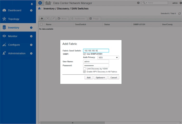
8. Click Add.
9. Repeat steps 1-8 to add the second MDS switch.
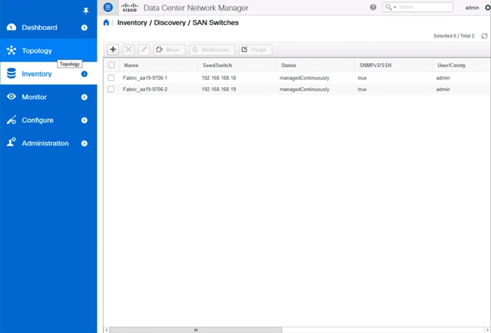
Configuring Device Aliases for the VSP and ESXi hosts
The device aliases for the MDS fabrics will be created before the zoning can occur. To create the device aliases, follow these steps:
1. Select Configure -> Device Aliases.
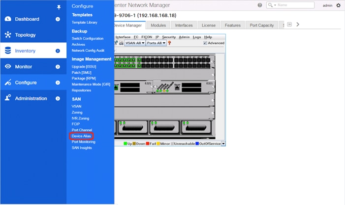
2. Select the appropriate MDS from the Fabric drop-down list and click Create to specify device aliases.
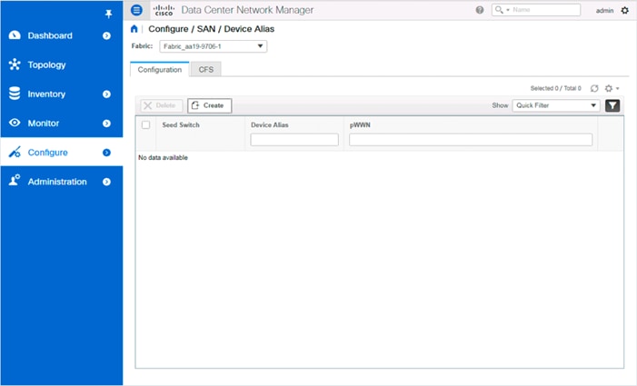
3. Continuing to use the VSP G370 to the UCS 6454 as an example, populate the following tables with data from the Table 24 and Table 25 of targets and the Table 28 and Table 29 of initiators:
Table 28 Fabric A Targets and Initiators
|
|
Name |
WWN/WWPN Example Environment (Port Name) |
WWN/WWPN Customer Environment |
| Target |
G370-CL1-A |
50:06:0e:80:12:c9:9a:00 |
|
| Target |
G370-CL2-B |
50:06:0e:80:12:c9:9a:11 |
|
| Initiator |
VSI-G370-01 |
20:00:00:25:B5:54:0A:00 |
|
| Initiator |
VSI-G370-02 |
20:00:00:25:B5:54:0A:01 |
|
Table 29 Fabric B Targets and Initiators
|
|
|
WWN/WWPN Example Environment (Port Name) |
WWN/WWPN Customer Environment |
| Target |
G370-CL3-B |
50:06:0e:80:12:c9:9a:21 |
|
| Target |
G370-CL4-A |
50:06:0e:80:12:c9:9a:30 |
|
| Initiator |
VSI-G370-01 |
20:00:00:25:B5:54:0B:00 |
|
| Initiator |
VSI-G370-02 |
20:00:00:25:B5:54:0B:01 |
|
4. Select a pWWN.
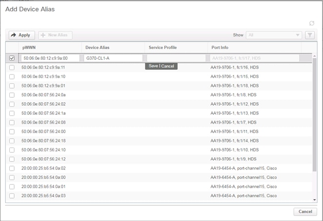
5. Click the Device Alias column and provide an appropriate alias.
6. Click Save.
7. Repeat steps 1-5 for each VSP target and Service Profile initiator entry listed, for both MDS fabrics.
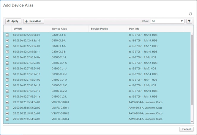
8. Click Apply.
9. Repeat this process for the other fabric, creating device aliases for the attached devices.
Create Host Zoning
To create host zoning, follow these steps:
1. Select Configure and pick Zoning within the SAN subsection.
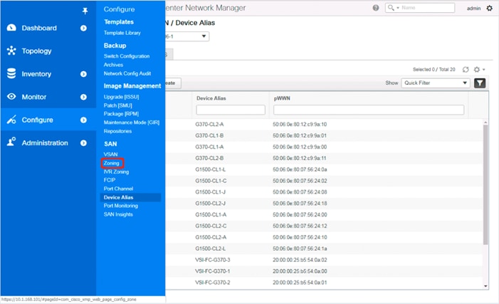
2. Adjust the VSAN to be appropriate for the zoning between hosts and the VSP.
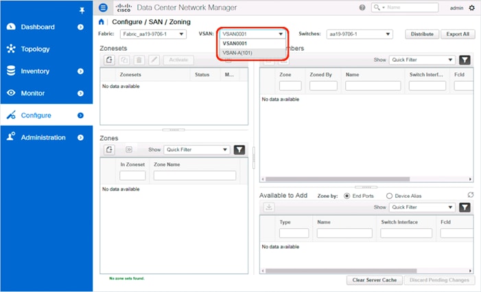
3. Click the Create Zoneset button within Zonesets.
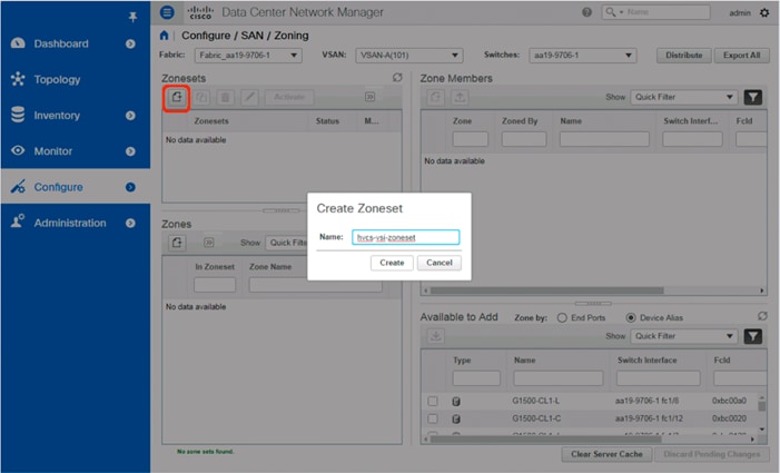
4. With the new zoneset selected, click the Create Zone button within Zones.
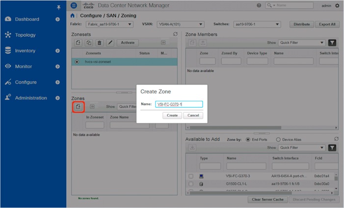
5. Specify an appropriate name for the zone.
6. Click Create.
7. Select the newly created zone and select the appropriate host device alias from the bottom right with the Available to Add section:
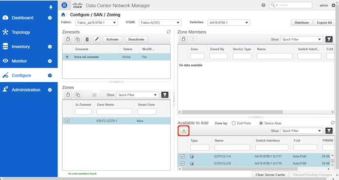
8. Click the green Add Member button within Available to Add.
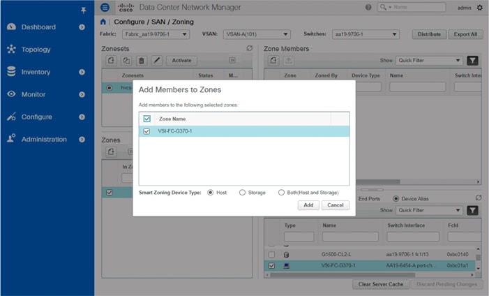
9. Make sure that Host is selected for the host being added and click Add.
10. With the zone still selected, and pick the appropriate VSP device aliases from the bottom right with the Available to Add section:
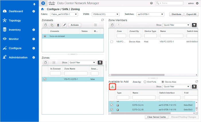
11. Make sure that Storage is selected for the VSP devices being added and click Add.
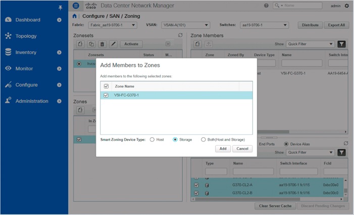
12. With the new zone still selected, click the drop-down list within Zones and select Enable Smart Zoning.
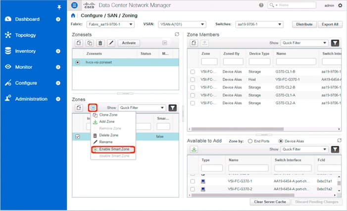
13. Additional zones for hosts associated to the same VSP can be created in the same manner or by selecting the first zone created and selecting Clone Zone from the drop-down list.
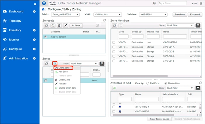
14. Specify the new host to be associated with the cloned zone:
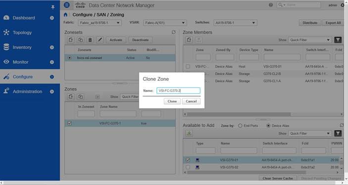
15. Click Clone.
16. Deselect the original zone and select the cloned zone.
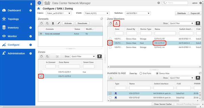
17. Select the host carried over from the cloning operation within the Zone Members section and click Remove Member.
18. Repeat the process of selecting the Enable Smart Zone for the new zone.
19. Select the new zone.
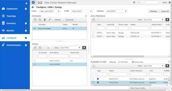
20. Find the host intended for this new zone within the Available to Add section.
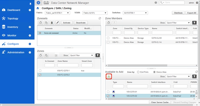
21. Click Add Member.
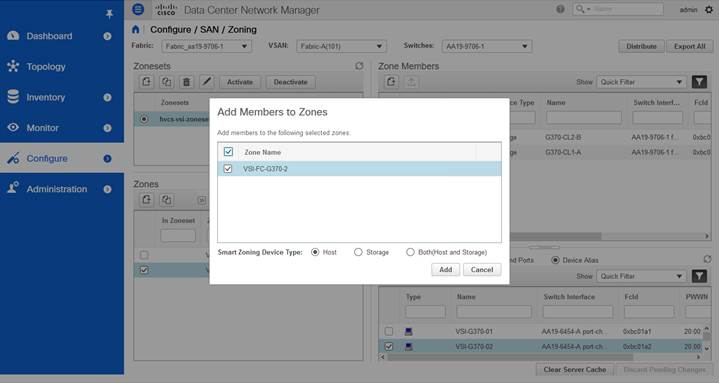
22. Ensure that Host is selected for Smart Zoning Device Type and click Add.
23. Repeat steps 1-22 to add zones for all additional hosts.
24. Select all created Zones and find Add Zone from the drop-down list to add to the zoneset.
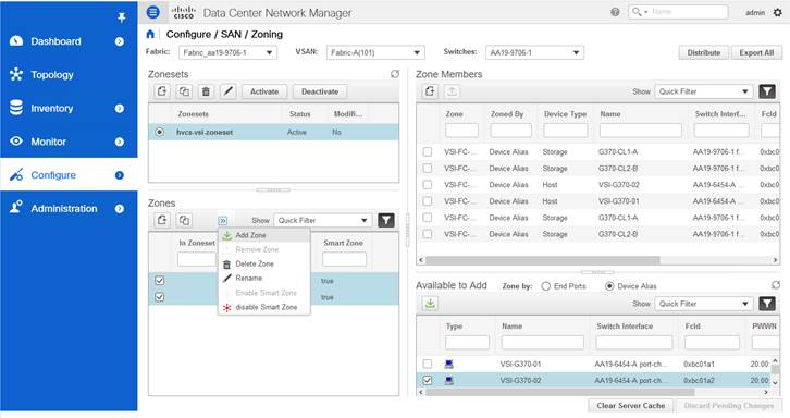
25. Zones will now show checkmarks as In Zoneset.
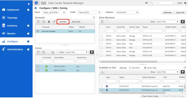
26. Click Activate to activate the zoneset.
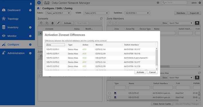
27. Click Activate.
The configuration steps in this section assume that parity groups and LDEVs have been configured on the Hitachi VSP as part of the solution build/configuration by a partner or Hitachi professional services. If parity groups have not been configured on the Hitachi VSP, refer to the Hitachi Storage Virtualization Operating System documentation for creating parity groups before continuing with this section.
Ensure that you have planned which parity groups and LDEVs to use for specific storage requirements. Your configuration may vary based on the types of drives ordered with your VSP and the parity groups configured on it.
Create a Hitachi Dynamic Provisioning Pool for UCS Server Boot LDEVs
To begin the provisioning process to create the Boot LDEVs that will be used as boot LUNs, follow these steps:
1. Log into Hitachi Storage Navigator.
2. From the left Explorer pane select the Storage Systems tab.
3. Expand the storage system being configured. Highlight the Pools element in the navigation tree and click Create Pools to instantiate the Create Pools dialog box.
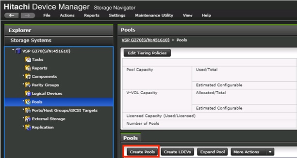
4. Configure the following items in the left pane of the Create Pools dialog box:
a. Pool Type: Dynamic Provisioning
b. System Type: Open [Only an option when configuring the G1500]
c. Multi-Tier Pool: Disable
d. Data Direct Mapping: Disable
e. Pool Volume Selection: Manual
5. Select the Drive Type/RPM and RAID Level desired for the UCS server boot LDEV backing pool using the drop-down lists and click Select Pool VOLs to instantiate the Select Pool VOLs dialog box.
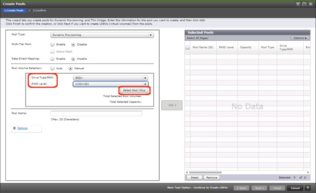
6. Within the left pane of the Select Pool VOLs dialog box, select the checkbox next to the LDEVs to be used for the UCS server boot LDEV dynamic provisioning pool.
7. Click Add to move the selected LDEV to the right pane of the dialog, then click OK to return to the Create Pools dialog box.
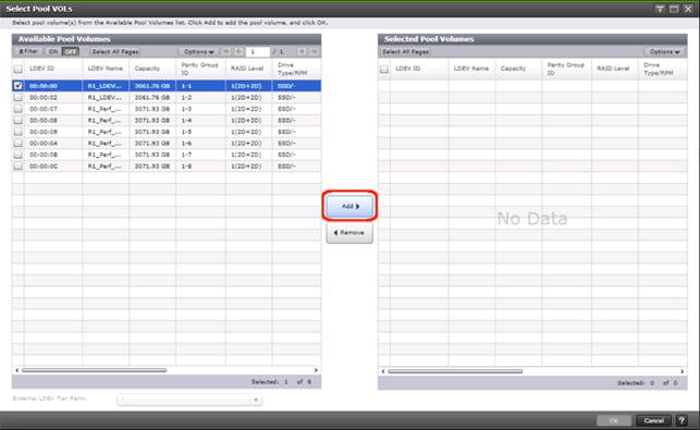
8. You should now see values for Total Selected Pool Volumes and Total Selected Capacity shown under the Select Pool VOLs button. Give the dynamic provisioning pool a descriptive Pool Name, then click Add to add the pool to be created to the Selected Pools pane in the dialog.
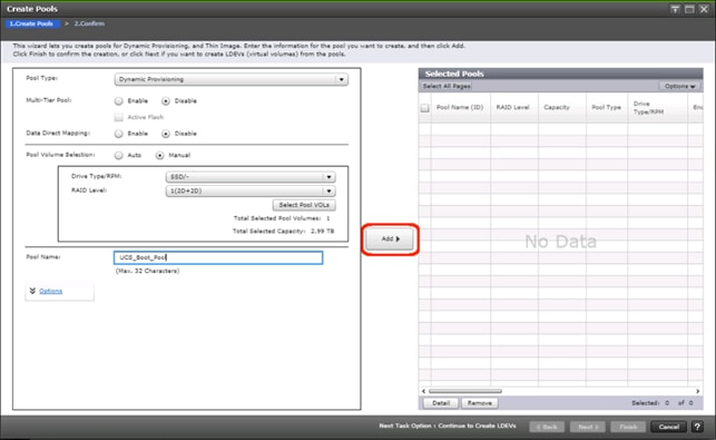
9. Click Finish.
10. Review the configuration for the pool to be created in the Create Pools confirmation dialog box and ensure the Go to tasks window for status checkbox is checked then click Apply.
11. The tasks status window will appear, wait for the task status to show complete before moving onto the next step.
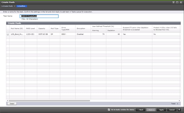
Create a Hitachi Dynamic Provisioning Pool for UCS Server VMFS Volume LDEVs
Follow the same steps as in section Create a Hitachi Dynamic Provisioning Pool for UCS Server Boot LDEVs to create the dynamic provisioning pool for the UCS Server VMFS volume LDEVs, selecting the Drive Type/RPM, RAID Level, and number of Pool VOLs desired for the pool backing the VMFS volumes in the solution.
Create Host Groups for Cisco UCS Server vHBAs on Each Fabric
An individual host group must be created on each physical fibre channel port on the VSP for each vHBA attached to its respective fabric. The number of host groups created will depend on the number of paths per LDEV. Ensure you have documented the specific ports on each fabric being used on the VSP, their WWNs, and each vHBA WWPN before you proceed with this section and ensure that all initiators for the UCS Service Profiles you will be creating host groups for are showing as logged into the respective VSP fibre channel ports by following the steps below.
To create Host Groups for UCS server vHBAs on each fabric, follow these steps:
1. From the left Explorer pane within Hitachi Storage Navigator, select the Storage Systems tab and expand the storage system being configured.
2. Highlight the Ports/Host Groups/iSCSI Targets element in the navigation tree and select the Login WWNs/iSCSI Names tab.
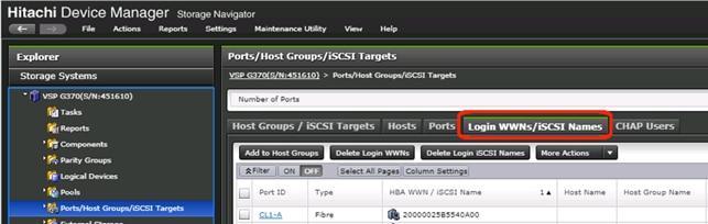
3. Review the list of WWNs and associated ports. You should be able to see each vHBA assigned to each fabric associated with each port on the VSP that it is zoned to.
4. Click the column names to sort the information to make this task easier or utilize the Filter feature to limit the number of records displayed. If any vHBA WWNs do not show in the list, go back and double check the zoning configuration on the MDS.
5. With the Ports/Host Groups/iSCSI Targets element in the navigation tree still selected, click the Host Groups/iSCSI Targets tab.
6. Click Create Host Groups to instantiate the Create Host Groups dialog box.
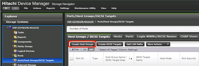
7. Host groups will be created separately for fabric A and fabric B vHBAs. Start with the fabric A host group for an individual UCS Service Profile and modify the following within the Create Host Groups dialog box:
a. Host Group Name: Provide a descriptive name for the host and ensure there is an identifier for the fabric you are configuring (i.e., VSI-G370-1_Fab_A)
b. Host Mode: Select 21 [VMware Extension] from the drop-down list.
c. Host Mode Options: For each of the following Host Mode Options, find the Mode Number in the pane, select the checkbox, and click the Enable button:
i. 54 – (VAAI) Support Option for the EXTENDED COPY command
ii. 63 – (VAAI) Support option for vStorage APIs based on T10 standards
iii. 114 – The automatic asynchronous reclamation on ESXi6.5 or later
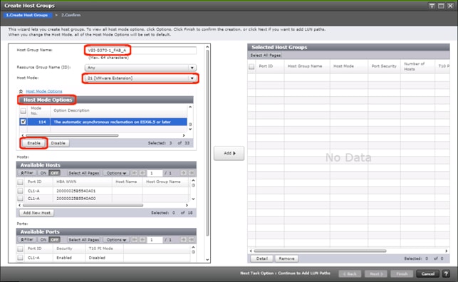
8. Write down the WWN information from Table 28 and Table 29 from the previous Create Device Aliases section into the following tables:
Table 30 Fabric A Targets and Initiators
|
|
Name |
WWN/WWPN Example Environment (Port Name) |
WWN/WWPN Customer Environment |
| Target |
G370-CL1-A |
50:06:0e:80:12:c9:9a:00 |
|
| Target |
G370-CL2-B |
50:06:0e:80:12:c9:9a:11 |
|
| Initiator |
VSI-G370-01 |
20:00:00:25:B5:54:0A:00 |
|
| Initiator |
VSI-G370-02 |
20:00:00:25:B5:54:0A:01 |
|
Table 31 Fabric B Targets and Initiators
|
|
|
WWN/WWPN Example Environment (Port Name) |
WWN/WWPN Customer Environment |
| Target |
G370-CL3-B |
50:06:0e:80:12:c9:9a:21 |
|
| Target |
G370-CL4-A |
50:06:0e:80:12:c9:9a:30 |
|
| Initiator |
VSI-G370-01 |
20:00:00:25:B5:54:0B:00 |
|
| Initiator |
VSI-G370-02 |
20:00:00:25:B5:54:0B:01 |
|
9. Scroll down in the left pane of the Create Host Groups dialog.
10. Within the Available Hosts section, click Filter.
11. Create an Attribute/Value filter of:
- HBA WWN
- Using “contains” as a qualifier
- Using the last four characters of the Fabric A initiator for the host
![]() This will be without “:” characters from the above table, and assuming that the last four characters is sufficient to produce a unique matching value. If necessary, use a larger identifying character string.
This will be without “:” characters from the above table, and assuming that the last four characters is sufficient to produce a unique matching value. If necessary, use a larger identifying character string.
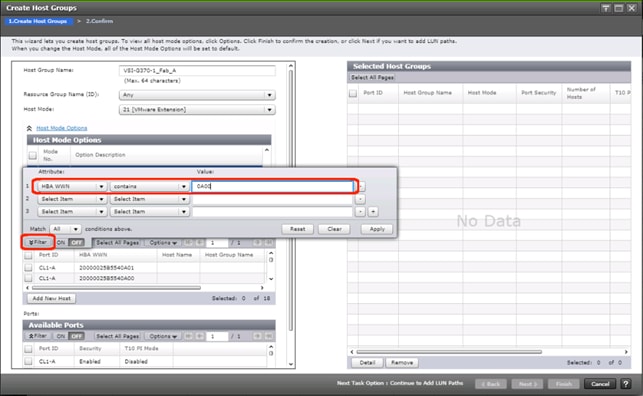
12. Click Apply.
13. Click Filter again to hide the filter rules dialog box.
14. Select the checkbox for the first port shown in the filtered list within the Available Hosts section.
15. Within the Available Ports section, check the checkboxes for all ports zoned to the host within Fabric A only.
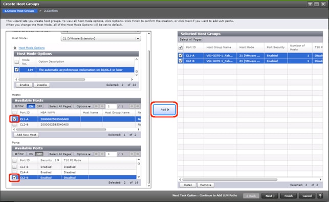
![]() In the screenshot above, the CL1-A port entry was also selected within the Available Ports section.
In the screenshot above, the CL1-A port entry was also selected within the Available Ports section.
16. Click Add, then click Finish.
17. Review the host group configuration for the Fabric A host groups for the UCS Service Profile being configured.
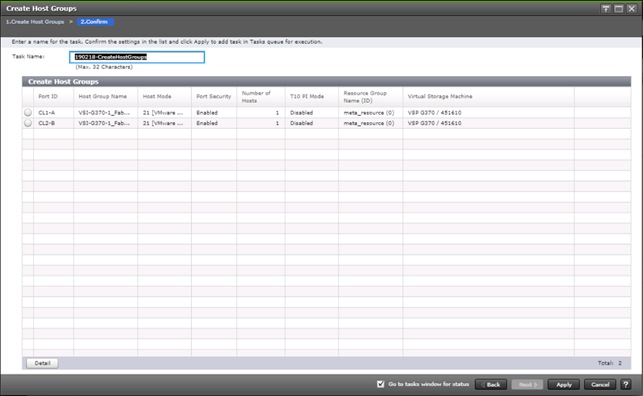
18. Click Apply.
19. Repeat steps 1-18 to create the host groups for all remaining initiator WWN from the Fabric A and Fabric B tables above, using a descriptive name for the host on Fabric A/B, the vHBA WWN on Fabric A/B for the UCS Service Profile, and the associated Fabric A/B ports on the Hitachi VSP.
Create Boot LDEVs for Each UCS Service Profile and Add LDEV Paths
Individual boot LDEVs must be created for each UCS Service Profile for the ESXi hypervisor to be installed onto. Prior to beginning these steps, ensure you have identified the fibre channel ports on the Hitachi VSP that will be used for presentation of the boot LDEVs to the UCS servers. Please note that a maximum of four paths can be used within the UCS Service Profile (two on each fabric) as boot targets.
To create boot LDEVs for each UCS service profile and add LDEV paths, follow these steps:
1. From the left Explorer pane within Hitachi Storage Navigator, select the Storage Systems tab and expand the storage system being configured.
2. Expand the Pools element in the navigation tree and highlight the UCS Boot pool previously created for use as the backing storage for the UCS boot LDEVs.
3. Select the Virtual Volumes tab in the right hand pane and click Create LDEVs to instantiate the Create LDEVs dialog.
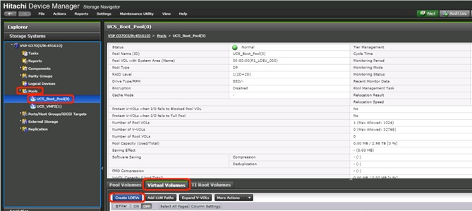
4. Modify the following within the Create LDEVs dialog:
- LDEV Capacity: Enter the capacity desired for the UCS Service Profile boot LDEV. Note that ESXi requires a minimum of 5.2GB for a boot LDEV as documented by VMware.
- Number of LDEVs: 1
- LDEV Name: Provide a descriptive name and numeric identifier for the boot LDEV. For ease of identification, it is recommended that the server name or other identifier specific to the service profile being configured be entered in the Prefix field.

5. Click Add and verify that the boot LDEV is listed in the right-hand Selected LDEVs pane, then click Next.
6. The Select LDEVs screen shows the selected LDEVs to which the paths will be added.
7. Ensure the newly created boot LDEV is the only LDEV in the Selected LDEVs pane then click Next.
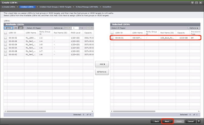
8. The Select Host Groups/iSCSI Targets screen shows all of the host groups that can be assigned to the boot LDEV as a path.
9. Click Filter then create an Attribute/Value filter:
- Host Group Name
- Using “contains” as a qualifier
- <value which contains text unique to UCS server profile>
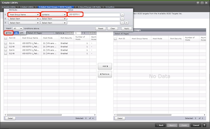
10. Click Apply.
11. Click Filter again to hide the filter rules dialog box.
12. Select the checkboxes for the ports being used as boot LDEV paths in your configuration. Depending on the pathing design used, you may have fewer than four paths for the boot LDEV, but there should be a minimum of one path per fabric used.
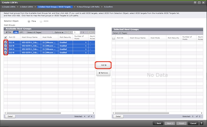
13. Click the Add to populate the Selected Host Groups pane with the selected host groups then click Next.
14. The View/Change LUN Paths screen shows the LDEV you are adding paths to and the associated host LUN ID that will be presented to the host on a per path basis.
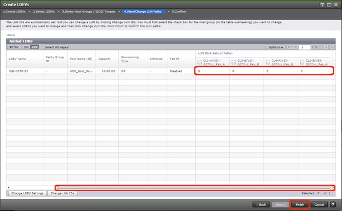
15. Use the scrollbar at the bottom of this screen to review the LUN ID assigned and ensure that all LUN IDs are set to zero then click Finish.

16. Review the LDEV details and LUN ID configuration of the boot LDEV being created then click Apply to create the LDEV and add paths to the UCS Service Profile.
17. Repeat steps 1-16 to create the boot LDEVs and to assign paths for all other UCS Service Profiles, using a unique LDEV name and associated Host Group Name associated to each UCS Service Profile.
Create Shared VMFS LDEVs and Add LDEV Paths
VMFS LDEVs need to be created for shared VMFS volumes used for virtual machine storage across multiple ESXi servers which share resources within a vSphere cluster. Prior to beginning these steps, ensure you have identified the fibre channel ports on the Hitachi VSP that will be used for presentation of the VMFS LDEVs to the UCS servers. Depending on the pathing design you are using, additional or fewer paths may be configured as compared to the steps below.
![]() A minimum of two paths should be used for shared VMFS LDEVs (one path per fabric).
A minimum of two paths should be used for shared VMFS LDEVs (one path per fabric).
To create shared VMFS LDEVs and add LDEV paths, follow these steps:
1. From the left Explorer pane within Hitachi Storage Navigator, select the Storage Systems tab and expand the storage system being configured.
2. Expand the Pools element in the navigation tree and highlight the pool previously created for use as the backing storage for VMFS volumes, select the Virtual Volumes tab in the right hand pane, and click Create LDEVs to instantiate the Create LDEVs dialog.
3. Modify the following within the Create LDEVs dialog:
- LDEV Capacity: Enter the capacity desired for the VMFS LDEV.
- Number of LDEVs: 1
- LDEV Name: Provide a descriptive name and numeric identifier for the VMFS LDEV. For ease of identification, it is recommended that the cluster name or other identifier specific to the VMFS volume being configured be entered in the Prefix field.
4. Click Add and verify that the VMFS LDEV is listed in the right-hand Selected LDEVs pane, then click Next.
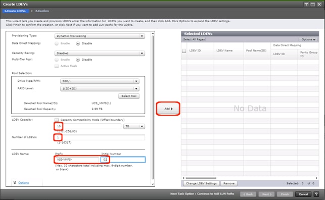
5. The Select LDEVs screenshot shows the selected LDEVs to which the paths will be added.
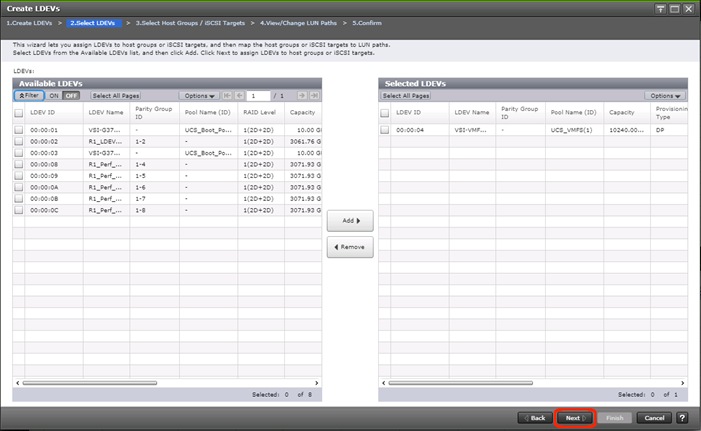
6. Ensure the newly created VMFS LDEV is the only LDEV in the Selected LDEVs pane, then click Next.
7. The Select Host Groups/iSCSI Targets screen shows all of the host groups that can be assigned to the VMFS LDEV as a path.
8. Click Filter, then create multiple Attribute/Value:
- Host Group Name
- Using “contains” as a qualifier
- <value which contains text unique to UCS server profiles to use the VMFS volume>
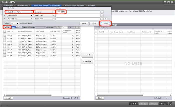
9. Click Apply.
10. Click Filter again to hide the filter rules dialog box.
11. Select the checkboxes for the ports being used as VMFS LDEV paths in your configuration.
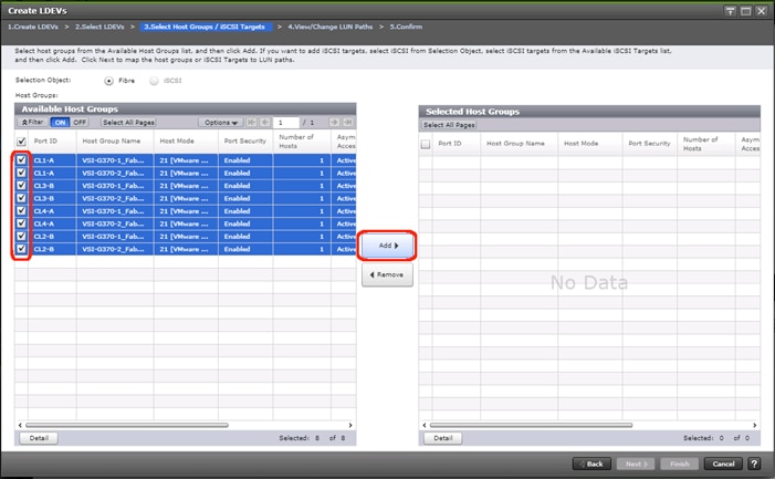
![]() Depending on the pathing design used, you may have additional or fewer than four paths for the VMFS LDEV, but there should be a minimum of one path per fabric used.
Depending on the pathing design used, you may have additional or fewer than four paths for the VMFS LDEV, but there should be a minimum of one path per fabric used.
12. Click Add to populate the Selected Host Groups pane with the selected host groups, then click Next.
13. The View/Change LUN Paths screen shows the LDEV you are adding paths to and the associated host LUN ID that will be presented to the host on a per path basis.
14. Use the scrollbar at the bottom of this screen to review the LUN ID assigned and ensure that all LUN IDs are set to a consistent value other than zero for all paths.
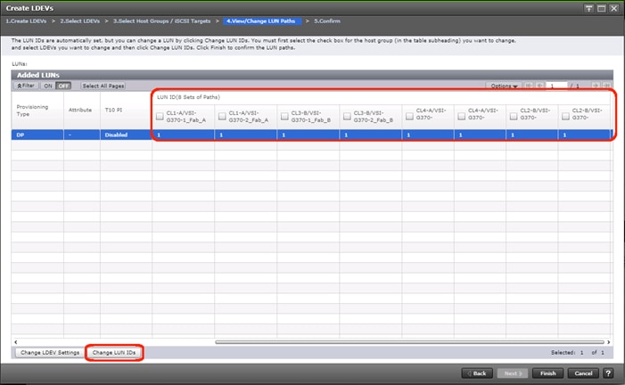
![]() If other LDEVs have been assigned to one host but not others, you will need to modify the Host LUN ID assignment to the next Host LUN ID that is consecutive across all hosts/paths.
If other LDEVs have been assigned to one host but not others, you will need to modify the Host LUN ID assignment to the next Host LUN ID that is consecutive across all hosts/paths.
15. Ensure you use the scrollbar at the bottom of the dialog to double-check that all Host LUN IDs are set consistently across all paths.
16. To do this, select the checkbox for all ports/paths listed, select the checkbox for the LDEV ID on the left side of the pane, then click Change LUN IDs.
17. The Change LUN IDs dialog will appear; enter the next Host LUN ID available across all paths, then click Finish.
18. Review the LDEV details and LUN ID configuration of the VMFS LDEV being created.
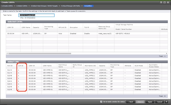
![]() If the output is long enough, use the scrollbar on the right side of the Added LUNs window to ensure the LUN ID column contains the same LUN ID for each port listed.
If the output is long enough, use the scrollbar on the right side of the Added LUNs window to ensure the LUN ID column contains the same LUN ID for each port listed.
19. Click Apply to create the LDEV and add paths to the UCS Service Profiles which will share this LDEV as a VMFS volume.
20. Repeat steps 1-18 to create additional shared VMFS LDEVs and to assign paths for all UCS Service Profiles which will share access to the VMFS LDEVs used for VMFS volumes.
This section provides detailed instructions to install VMware ESXi 6.7 U2 in the environment.
Several methods exist for installing ESXi in a VMware environment. These procedures focus on how to use the built-in keyboard, video, mouse (KVM) console and virtual media features in Cisco UCS Manager to map remote installation media to individual servers and connect to their boot logical unit numbers (LUNs).
Download Cisco Custom Image for ESXi 6.7 U2
The VMware Cisco Custom Image will be needed for use during installation by manual access to the UCS KVM vMedia, or through a vMedia Policy covered in a previous subsection. If the Cisco Custom Image was not downloaded during the vMedia Policy setup, download it now by following these steps:
1. Click the following link: VMware vSphere Hypervisor Cisco Custom Image (ESXi) 6.7 U2.
2. You will need a user id and password for vmware.com to download this software.
3. Download the .iso file.
Log into Cisco UCS 6454 Fabric Interconnect
The IP KVM enables the administrator to begin the installation of the operating system (OS) through remote media. It is necessary to log in to the UCS environment to run the IP KVM.
To log in to the Cisco UCS environment, follow these steps:
1. Open a web browser to https:// <<var_ucs_mgmt_vip>>
2. Select the Launch UCS Manager Section in the HTML section to pull up the UCSM HTML5 GUI.
3. Enter admin for the Username, and provide the password used during setup.
4. Within the UCSM select Servers -> Service Profiles, and pick the first host provisioned, which should be named VSI-FC-G370-1.
5. Click Reset to ensure that the boot LUN is properly recognized by the UCS Service Profile.
6. Click the KVM Console option within Actions and accept the KVM server certificate in the new window or browser tab that is spawned for the KVM session.
7. Click the link within the new window or browser tab to load the KVM client application.
Set Up VMware ESXi Installation
![]() Skip this step if you are using vMedia policies. The ISO file will already be connected to KVM.
Skip this step if you are using vMedia policies. The ISO file will already be connected to KVM.
To prepare the server for the OS installation, follow these steps on each ESXi host:
1. In the KVM window, click Virtual Media icon ![]() in the upper right of the screen.
in the upper right of the screen.
2. Click Activate Virtual Devices.
3. Click Virtual Media again and select Map CD/DVD.
4. Browse to the ESXi installer ISO image file and click Open.
5. Click Map Device.
6. Click the KVM tab to monitor the server boot.
7. Boot the server by selecting Boot Server and clicking OK, then click OK again.
Install ESXi
To install VMware ESXi to the FC bootable LUN of the hosts, follow these steps on each host:
1. On reboot, the machine detects the presence of the ESXi installation media. Select the ESXi installer from the boot menu that is displayed.
2. After the installer is finished loading, press Enter to continue with the installation.
3. Read and accept the end-user license agreement (EULA). Press F11 to accept and continue.
4. Select the Boot LUN (10.00 GiB) that was previously set up as the installation disk for ESXi and press Enter to continue with the installation.
5. Select the appropriate keyboard layout and press Enter.
6. Enter and confirm the root password and press Enter.
7. The installer issues a warning that the selected disk will be repartitioned. Press F11 to continue with the installation.
8. After the installation is complete, if using locally mapped Virtual Media, click the Virtual Media tab and clear the checkmark next to the ESXi installation media. Click Yes.
![]() The ESXi installation image must be unmapped to make sure that the server reboots into ESXi and not into the installer. If using a vMedia Policy, this will be unnecessary as the vMedia will appear after the installed OS.
The ESXi installation image must be unmapped to make sure that the server reboots into ESXi and not into the installer. If using a vMedia Policy, this will be unnecessary as the vMedia will appear after the installed OS.
9. From the KVM window, press Enter to reboot the server.
Set Up Management Networking for ESXi Hosts
Adding a management network for each VMware host is necessary for managing the host. To add a management network for the VMware hosts, follow these steps on each ESXi host:
1. After the server has finished rebooting, press F2 to customize the system.
2. Log in as root, enter the corresponding password, and press Enter to log in.
3. (Optional)Select Troubleshooting Options and press Enter.
4. (Optional)Press Enter for Enable ESXi Shell.
5. (Optional)Scroll to Enable SSH and press Enter.
6. (Optional)Press Esc to return to the main menu.
7. Select the Configure Management Network option and press Enter.
8. Select Network Adapters option leave vmnic0 selected, arrow down to vmnic1 and press space to select vmnic1 as well and press Enter.
9. Select the VLAN (Optional) option and press Enter.
10. Enter the <<var_ib_mgmt_vlan_id>> and press Enter.
11. From the Configure Management Network menu, select IPv4 Configuration and press Enter.
12. Select the Set Static IP Address and Network Configuration option by using the space bar.
13. Enter <<var_vm_host_infra_01_ip>> for the IPv4 Address for managing the first ESXi host.
14. Enter <<var_ib_mgmt_vlan_netmask_length>> for the Subnet Mask for the first ESXi host.
15. Enter <<var_ib_gateway_ip>> for the Default Gateway for the first ESXi host.
16. Press Enter to accept the changes to the IPv4 configuration.
17. Select the DNS Configuration option and press Enter.
![]() Because the IP address is assigned manually, the DNS information must also be entered manually.
Because the IP address is assigned manually, the DNS information must also be entered manually.
18. Enter the IP address of <<var_nameserver_ip>> for the Primary DNS Server.
19. Optional: Enter the IP address of the Secondary DNS Server.
20. Enter the fully qualified domain name (FQDN) for the first ESXi host.
21. Press Enter to accept the changes to the DNS configuration.
22. Select the IPv6 Configuration option and press Enter.
23. Using the spacebar, select Disable IPv6 (restart required) and press Enter.
24. Press Esc to exit the Configure Management Network submenu.
25. Press Y to confirm the changes and return to the main menu.
26. The ESXi host reboots. After reboot, press F2 and log back in as root.
27. Select Test Management Network to verify that the management network is set up correctly and press Enter.
28. Press Enter to run the test.
29. Press Enter to exit the window, and press Esc to log out of the VMware console.
30. Repeat steps 1-29 for additional hosts provisioned, using appropriate values.
Log into VMware ESXi Hosts by Using VMware Host Client
To log in to the esxi-x (x is server number 1-8) ESXi host by using the VMware Host Client, follow these steps:
1. Open a web browser on the management workstation and navigate to the esxi-x management IP address. Respond to any security prompts.
2. Enter root for the user name.
3. Enter the root password.
4. Click Login to connect.
5. Repeat steps 1-4 to log into all the ESXi hosts in a separate browser tabs or windows.
![]() The first host will need to go through the initial configuration using the VMware Host Client if a vCenter Appliance is being installed to the VSI cluster. Subsequent hosts can be configured directly to the vCenter Server after it is installed to the first ESXi host, or all hosts can be configured directly within the vCenter if a pre-existing server is used that is outside of the deployed converged infrastructure.
The first host will need to go through the initial configuration using the VMware Host Client if a vCenter Appliance is being installed to the VSI cluster. Subsequent hosts can be configured directly to the vCenter Server after it is installed to the first ESXi host, or all hosts can be configured directly within the vCenter if a pre-existing server is used that is outside of the deployed converged infrastructure.
Set Up VMkernel Ports and Virtual Switch
To set up the VMkernel ports and the virtual switches on all the ESXi hosts, follow these steps:
1. From the Host Client, select Networking within the Navigator window.
2. In the center pane, select the Port groups tab.
3. Right-click the VM Network port group and select the Remove option.
4. Right-click the Management Network and select Edit Settings.
5. Expand NIC teaming and select vmnic1 within the Failover order section.
6. Click the Mark standby option.
7. Click Save
8. Click the Add port group option.
9. Name the port group IB-Mgmt.
10. Set the VLAN ID to <<IB-Mgmt VLAN ID>>.
11. Click Add.
12. Right-click the IB-Mgmt port group and select the Edit Settings option.
13. Expand NIC teaming and select Yes within the Override failover order section.
14. Select vmnic1 within the Failover order section.
15. Click the Mark standby option.
16. Click Save.
17. In the center pane, select the Virtual switches tab.
18. Right-click vSwitch0 and select Edit settings.
19. Change the MTU to 9000.
20. Expand NIC teaming and highlight vmnic1. Select Mark active.
21. Click Save.
22. Select the VMkernel NICs tab in the center pane.
23. Select Add VMkernel NIC.
24. Enter vMotion within the New port group section.
25. Set the VLAN ID to <<vMotion VLAN ID>>
26. Change the MTU to 9000
27. Click the Static option within IPv4 settings and expand the section.
28. Enter the Address and Subnet mask to be used for the ESXi vMotion IP.
29. Change the TCP/IP stack to vMotion stack.
30. Click Create.
![]() Optionally, with 40GE vNICs, you can create two additional vMotion VMkernel NICs in the same subnet and VLAN to take advantage of the bandwidth. These will need to be in new dedicated port groups for the new vMotion VMkernels.
Optionally, with 40GE vNICs, you can create two additional vMotion VMkernel NICs in the same subnet and VLAN to take advantage of the bandwidth. These will need to be in new dedicated port groups for the new vMotion VMkernels.
31. Re-select the Port groups tab.
32. Right-click the vMotion port group and select the Edit settings option.
33. Expand the NIC Teaming section and select Yes for Override failover order.
34. Highlight vmnic0 and select Mark standby.
35. Highlight vmnic1 and select Mark active.
36. Click Save.
37. Repeat steps 32-36 if additional vMotion port groups were created.
Add Provisioned Datastore to Configured Hosts
Adding a datastore directly to the host is unnecessary if an existing vCenter is used for the VSI resources. The next section will cover the optional deployment of the vCenter Server Appliance (VCSA) within the stack that will be deployed to this initial datastore.
Add Datastores to Hosts
When a LDEV has been created via Storage Navigator you will need to access a ESXi host within the VSI cluster to onboard it as an VMFS datastore. To deploy a datastore to a host, follow these steps:
1. Navigate to the IP address or FQDN of your ESXi host. Enter your username and password; click Log in.
2. From the navigator menu right-click storage, select New datastore.
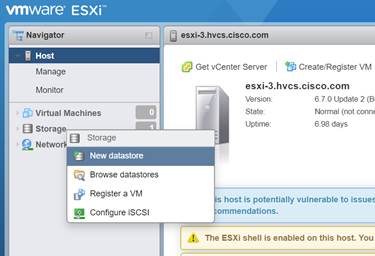
3. From the datastore creation wizard choose Create new VMFS datastore; click Next.
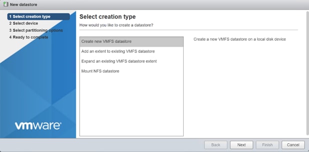
4. Select the Hitachi LDEV which you allocated via Storage Navigator and assign a datastore name then click Next.
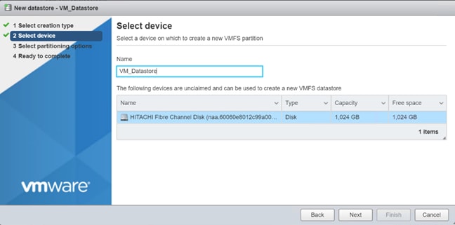
5. On Select partitioning options choose your VMFS version and click Next.
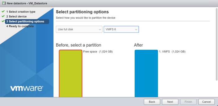
6. Review your setting and click Finish.
7. You can now view your datastore within your storage inventory.
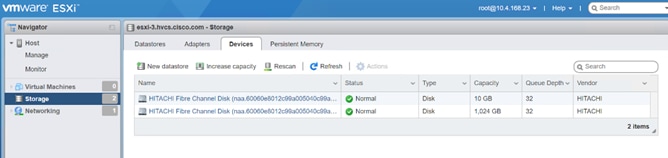
Build the VMware vCenter Server Appliance (optional)
The VCSA deployment consists of 2 stages: install and configuration. To build the VMware vCenter virtual machine, follow these steps:
1. Download the VCSA ISO from VMware at https://my.vmware.com/group/vmware/details?downloadGroup=VC67U2C&productId=742&rPId=35624
2. Using ISO mounting software, mount the ISO image as a disk on the management workstation. (For example, with the Mount command in Windows Server 2012).
3. In the mounted disk directory, navigate to the vcsa-ui-installer > win32 directory and double-click installer.exe. The vCenter Server Appliance Installer wizard appears.
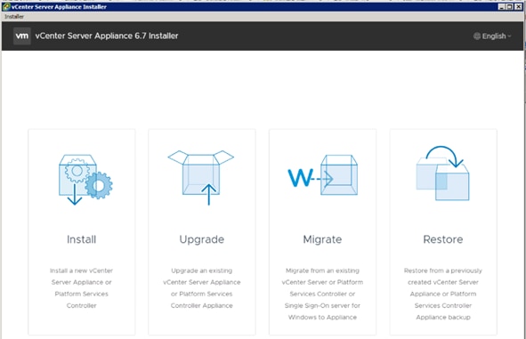
4. Click Install to start the vCenter Server Appliance deployment wizard.
5. Click Next in the Introduction section.
6. Read and accept the license agreement and click Next.
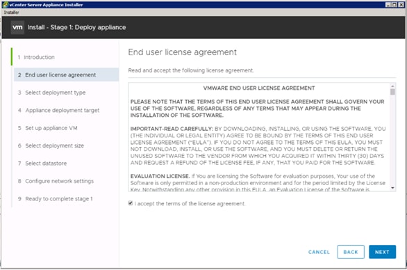
7. In the “Select deployment type” section, select vCenter Server with an Embedded Platform Services Controller and click Next.
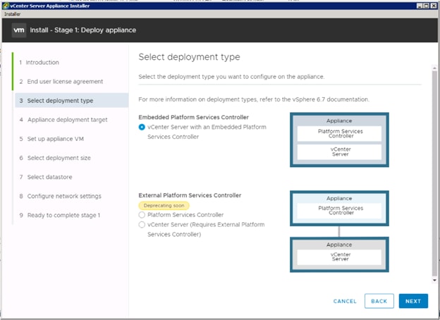
8. In the “Appliance deployment target”, enter the ESXi host name or IP address for the first configured VSI host, User name and Password. Click Next.
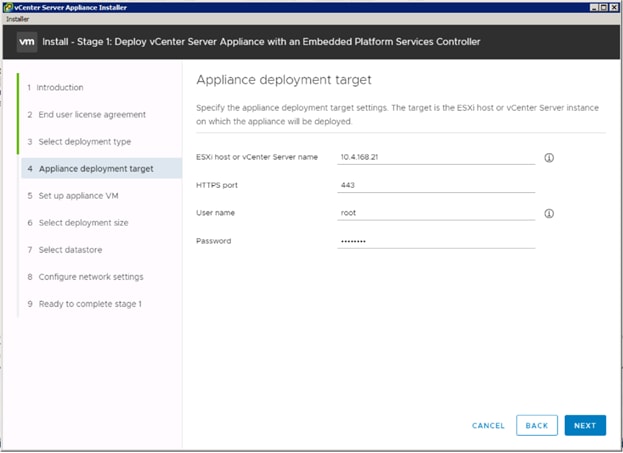
9. Click Yes to accept the certificate.
10. Enter the Appliance name and password details in the “Set up appliance VM” section. Click Next.
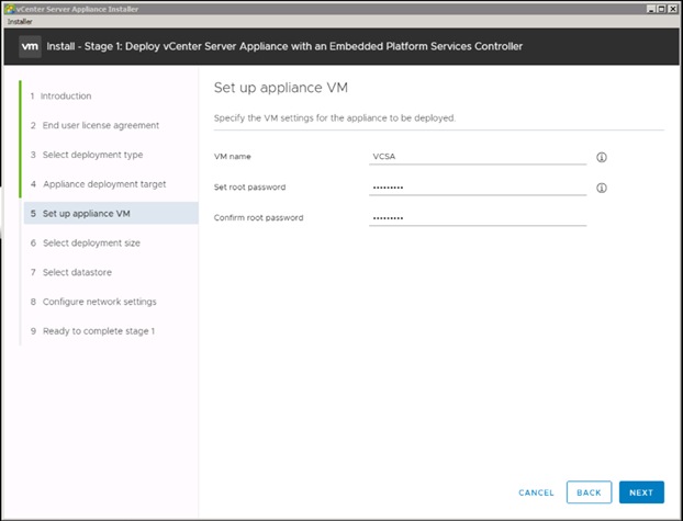
11. In the “Select deployment size” section, Select the deployment size and Storage size. For example, “Tiny” Deployment size was selected in this CVD.
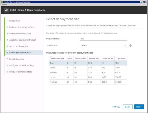
12. Click Next.
13. Select your preferred datastore, for example, the “VM Datastore” that was previously created.
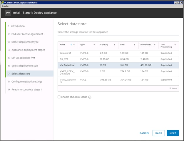
14. Click Next.
15. In the “Network Settings” section, configure the following settings:
a. Choose a Network: Core-Services Network
b. IP version: IPV4
c. IP assignment: static
d. System name: <vcenter-fqdn> (optional)
e. IP address: <vcenter-ip>
f. Subnet mask or prefix length: <vcenter-subnet-mask>
g. Default gateway: <vcenter-gateway>
h. DNS Servers: <dns-server>
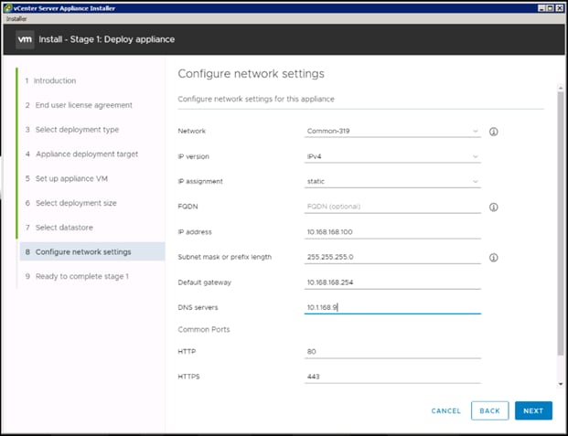
16. Click Next.
17. Review all values and click Finish to complete the installation.
18. The vCenter appliance installation will take a few minutes to complete.
19. Click Continue to proceed with stage 2 configuration.
20. Click Next.
21. In the Appliance Configuration, configure the below settings:
a. Time Synchronization Mode: Synchronize time with the ESXi host.
![]() Since the ESXi host has been configured to synchronize the time with an NTP server, vCenter time can be synced to ESXi host. Customer can choose a different time synchronization setting.
Since the ESXi host has been configured to synchronize the time with an NTP server, vCenter time can be synced to ESXi host. Customer can choose a different time synchronization setting.
b. SSH access: Enabled.
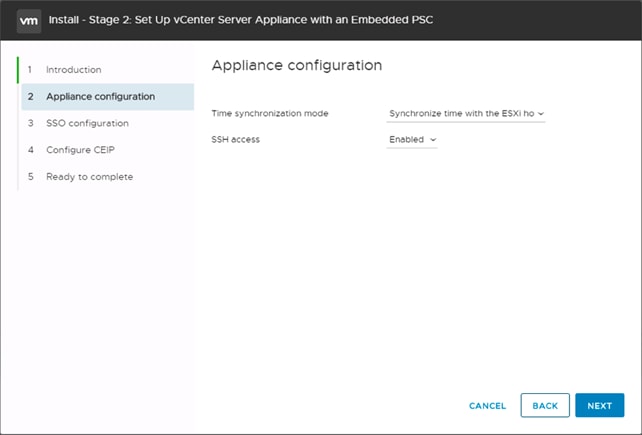
22. Click Next.
23. Complete the SSO configuration as shown below.
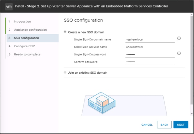
24. Click Next.
25. If preferred, select Join the VMware’s Customer Experience Improvement Program (CEIP).
26. Click Next.
27. Review the configuration and click Finish.
28. Click OK.
29. Make note of the access URL shown in the completion screen.
30. Click Close.
Set Up VMware vCenter Server
To set up the VMware vCenter Server, follow these steps:
1. Using a web browser, navigate to https://<vcenter-ip>/vsphere-client.
2. Log in using the Single Sign-On username (Administrator@vsphere.local) and password created during the vCenter installation.
3. Click “Create Datacenter” in the center pane.
4. Type a name for the Datacenter <NC Datacenter in our example> in the Datacenter name field.
5. Click OK.
6. Right-click the data center just created and select New Cluster.
7. Name the cluster VSI-Cluster.
8. Check the box to turn on DRS. Optionally adjust the Automation Level.
9. Check the box to turn on vSphere HA. Leave the default values.
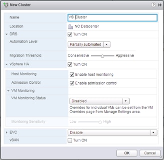
10. Click OK to create the new cluster.
11. On the left pane, expand the Datacenter.
12. Right click the VSI Cluster and select Add Host.
13. In the Host field, enter either the IP address or the FQDN name of one of the VMware ESXi hosts. Click Next.
14. Type root as the user name and the root password. Click Next to continue.
15. Click Yes to accept the certificate.
16. Review the host details and click Next to continue.
17. Assign a license or leave in evaluation mode and click Next to continue.
18. Click Next to continue.
19. Click Next to continue.
20. Review the configuration parameters. Click Finish to add the host.
21. Repeat steps 12 - 20 to add the remaining VMware ESXi hosts from both the sites to the cluster.
Create the VSI Datacenter
If a new Datacenter is needed, follow these steps on the vCenter:
1. Connect to the vSphere Web Client and right-click the vCenter icon under the Hosts and Clusters tab, selecting the New Datacenter option from the pulldown menu, or directly connect the Create Datacenter from the Getting Started page.
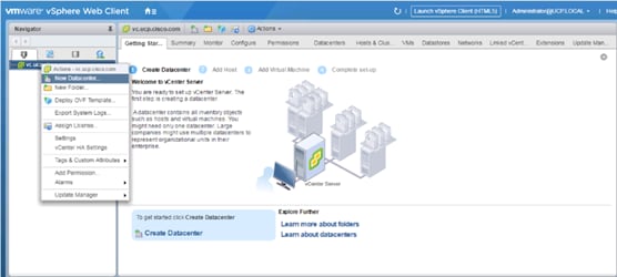
2. From the New Datacenter pop-up dialogue enter in a Datacenter name and click OK.
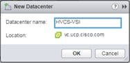
Add the VMware ESXi Hosts Using the VMware vSphere Web Client
To add the VMware ESXi Hosts using the VMware vSphere Web Client, follow these steps:
1. From the Hosts and Clusters tab, right-click the new or existing Datacenter within the Navigation window and select New Cluster… from the drop-down list.
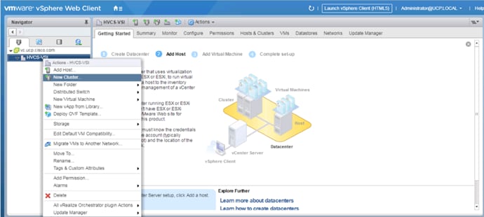
2. Enter a name for the new cluster, select the DRS and HA check mark boxes, leaving all other options with defaults.
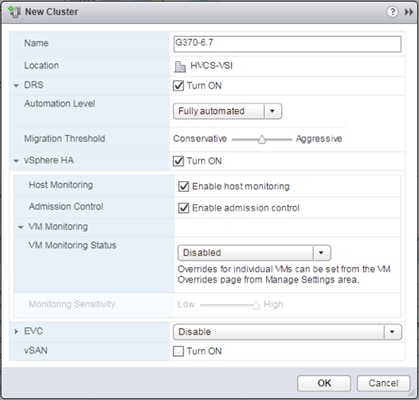
3. Click OK to create the cluster.
4. Right-click the newly created cluster and select the Add Host… drop-down list.
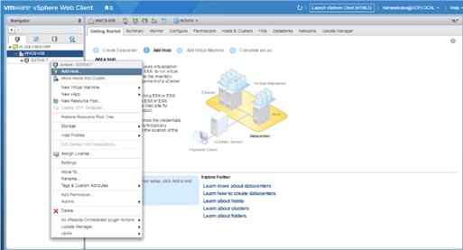
5. Enter the IP or FQDN of the first ESXi host and click Next.
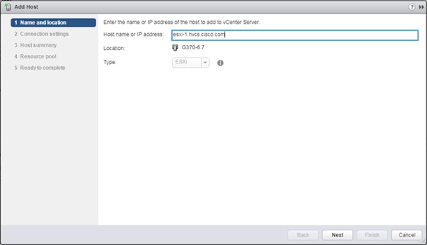
6. Enter root for the User Name, provide the password set during initial setup, and click Next.
7. Click Yes in the Security Alert pop-up to confirm the host’s certificate.
8. Click Next past the Host summary dialogue.
9. Provide a license by clicking the green + icon under the License title, select an existing license, or skip past the Assign license dialogue by clicking Next.
10. Leave lockdown mode Disabled within the Lockdown mode dialogue window and click Next.
11. Skip past the Resource pool dialogue by clicking Next.
12. Confirm the Summary dialogue and add the ESXi host to the cluster by clicking Next.
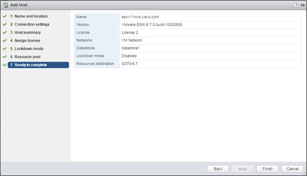
13. Repeat steps 1-12 for each ESXi host to be added to the cluster.
Configure NTP on ESXi Hosts
To configure Network Time Protocol (NTP) on the ESXi hosts, follow these steps on each host:
1. From the Configure tab, select the Time Configuration section under System.
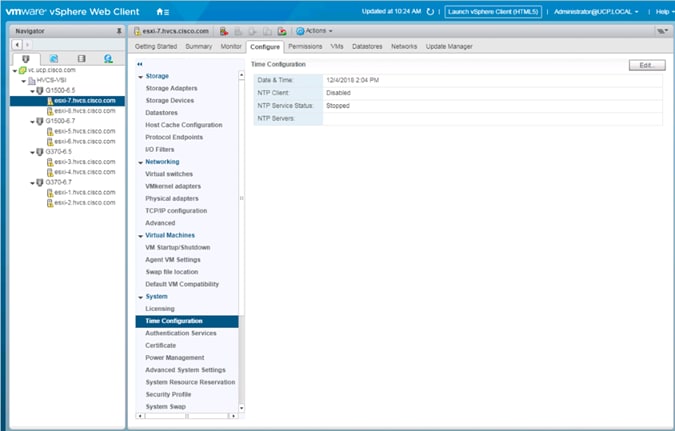
2. Click Edit.
3. Select the Use Network Time Protocol (Enable NTP client) option.
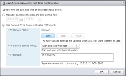
4. Enter an appropriate NTP server within the NTP Servers box, change NTP Service Startup Policy to Start and stop with host, and click the Start button.
5. Verify that NTP service is now running and the clock is now set to approximately the correct time.
![]() The NTP server time sync make take a few minutes.
The NTP server time sync make take a few minutes.
Create and Apply Patch Baselines with VUM
Critical patches are automatically available within VMware Update Manager (VUM) when using current versions of vCenter Server. A Patch Baseline will be made for the deployed vSphere release(s) and applied to each host to install appropriate patches.
To create the baselines and patch the new ESXi hosts, follow these steps:
1. Select the vCenter within the Hosts tab and find the Update Manager tab within the vCenter.
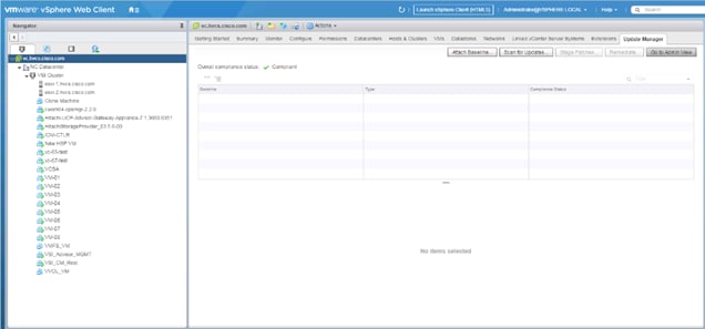
2. Click Go to Admin View.
3. Select Hosts Baselines within the Manage tab.
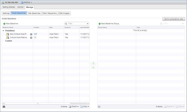
4. Click +New Baseline…
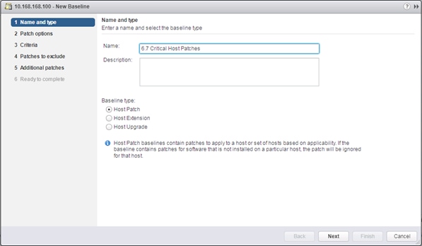
5. Provide a name for the Baseline, leave the Baseline type selected as Host Patch, and click Next.
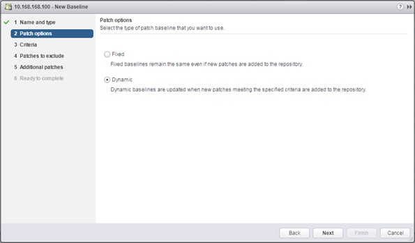
6. Leave the Patch options set as Dynamic and click Next.
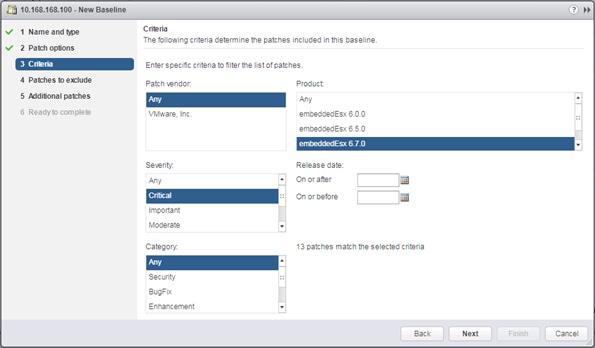
7. Select the target vSphere release for Product, and Critical within Severity.
8. Click Next.
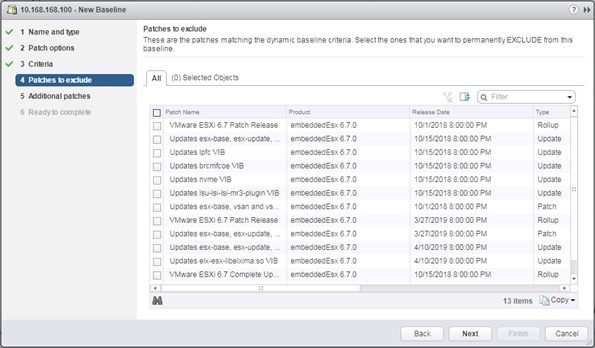
9. Exclude any patches if appropriate and click Next.
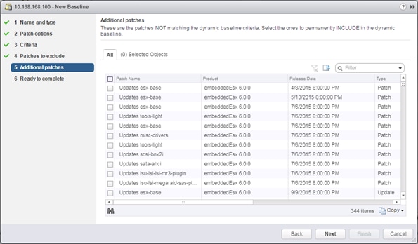
10. Select any additional patches if appropriate and click Next.
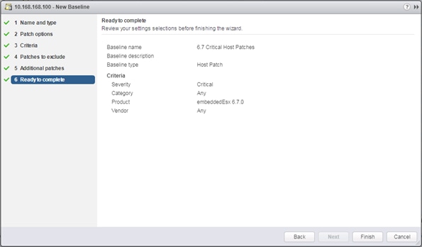
11. Review the selections and click Finish to create.
12. Go back to the Hosts view within Navigator.
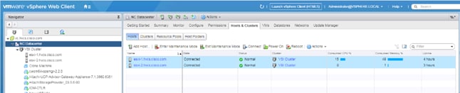
13. Select the Datacenter level, and within Hosts of the Hosts & Clusters tab, select the first host, and click Enter Maintenance Mode.
14. For the first host associated with the vSphere release of the baseline, select the host, and the Update Manager tab for that host.
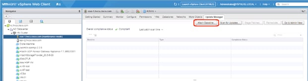
15. Click Attach Baseline….
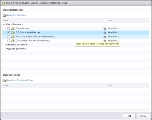
16. Select the appropriate Patch Baseline and click OK.
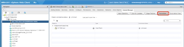
17. Click Remediate….
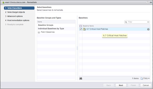
18. Select the baseline to apply and click Next.
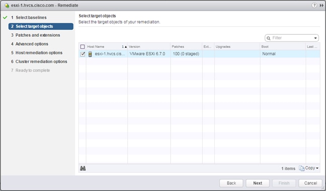
19. Select the hosts appropriate to the vSphere release specified for the baseline, if the baseline has been applied to multiple hosts, and click Next.
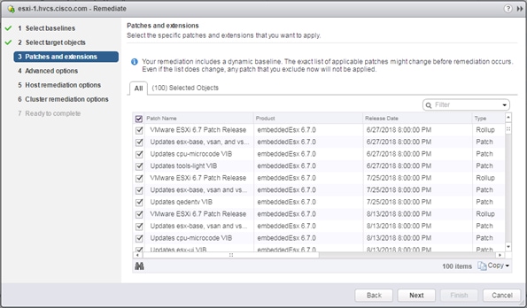
20. Unselect any patches that should not be applied and click Next.
21. Click Next past the Advanced options screen.
22. Click Next past the Host remediation options screen.
23. Click Next past the Cluster remediation options.
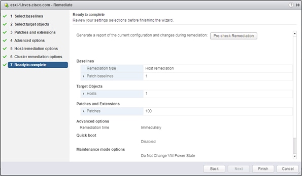
24. Review the settings and click Finish to run the patch baseline.
25. Repeat steps 13-24 for each additional host.
Cisco nfnic/nenic Updates Through VUM as Necessary
Cisco driver updates to the nfnic and or nenic can additionally be applied through VUM in the same manner that the Critical Patches have been applied. At the time of this CVD release there is a recommended nfnic driver that should be updated from what is included in the Cisco Custom ISO used during the vSphere installation that is documented. The nfnic can be downloaded from the VMware site at:
Alternately this driver can be found from the Cisco download site within the 40(4c) UCS VMware driver iso download:
https://software.cisco.com/download/home/283853163/type/283853158/release/4.0(4c)
![]()
To create a baseline for the Cisco drivers to update, follow these steps:
1. Within the vSphere Web Client connection to the vCenter, return to the Admin View of Update Manager.
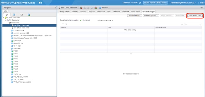
2. Select the Patch Repository tab and click Import Patches….
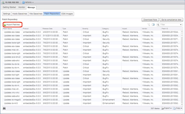
3. Select the offline_bundle zip file extracted either from the downloaded zip file from VMware, or the Driver ISO from Cisco.
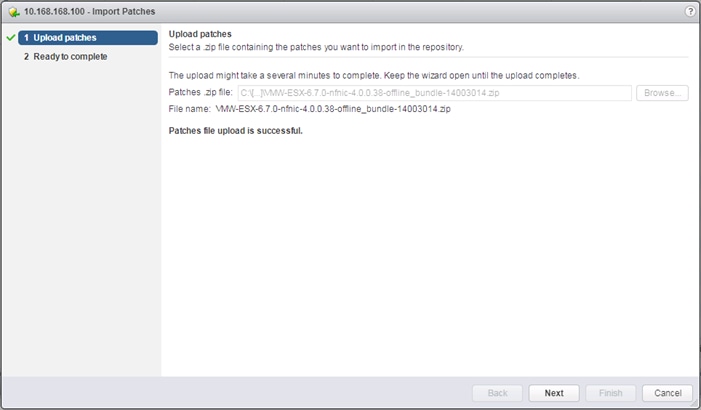
4. Click Next.
5. Click Finish.
6. Select the Host Baselines subsection of the Manage tab and click New Baseline…
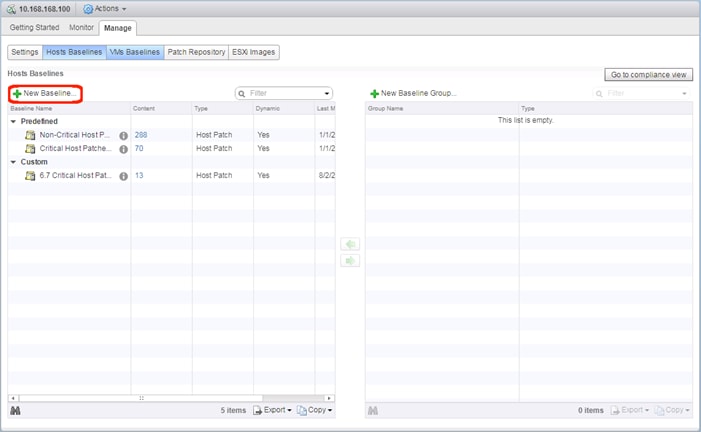
7. Provide a name for the driver baseline being created.
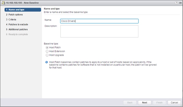
8. Click Next.
9. Set the Patch options to Fixed.
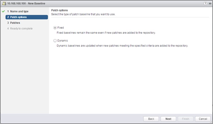
10. Click Next.
11. Provide a Filter of “Cisco” and select the nfnic patch.
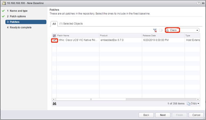
12. Click Next.
13. Review the Read to complete summary and click Finish.
14. Return to the host view for the first host and place it in maintenance mode.
15. Select the Updated Manager tab for the host and click Attach Baseline.
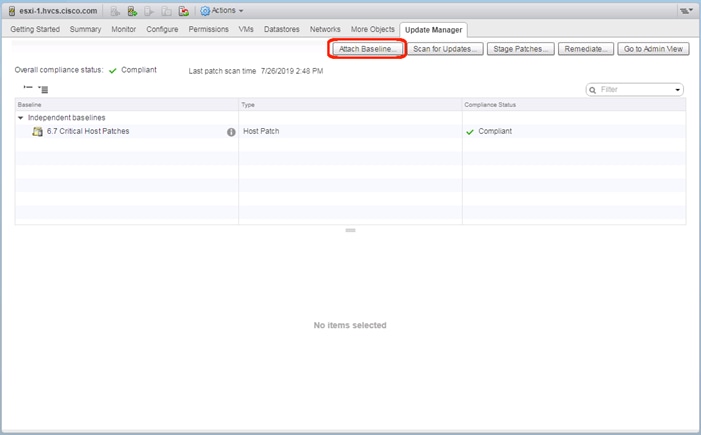
16. Select the Cisco Drivers baseline.
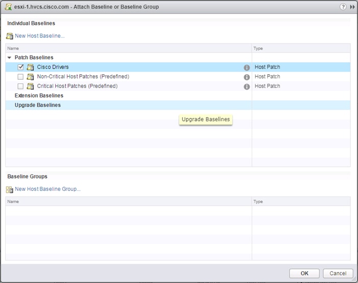
17. Click OK.
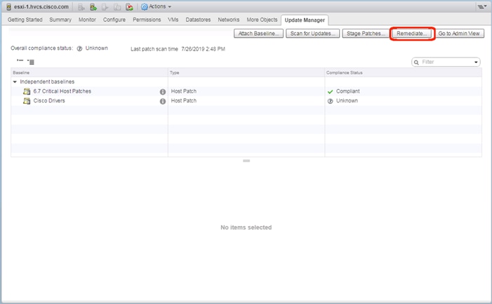
18. Click Remediate…
19. Select the Drivers baseline if the Critical patches baseline has already been run.
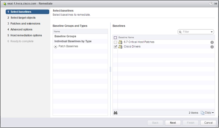
20. Click Next.
21. Click Next past the Select target objects screen.
22. Click Next past the Patches and extensions screen.
23. Click Next past the Advanced options screen.
24. Click Next past the Host remediation options screen.
25. Click Next past the Cluster remediation options screen.
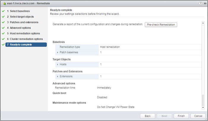
26. Verify the Ready to complete screen and click Finish.
Create Additional VMFS Datastore(s) using Hitachi Storage Management Software for VMware vSphere (Optional)
When ESXi hosts are deployed, users can supply additional VMFS datastore(s) to the UCS environment outside of Storage Navigator using Hitachi Storage Management products directly from the VMware vCenter user interface. Individual host groups and applicable dynamic provisioning pools via Storage Navigator must be created prior to using any of the below tools for storage allocation.
![]() Boot LDEVs can only be created using Storage Navigator. For more information, see section Create Boot LDEVs for Each UCS Service Profile and Add LDEV Paths.
Boot LDEVs can only be created using Storage Navigator. For more information, see section Create Boot LDEVs for Each UCS Service Profile and Add LDEV Paths.
Deployment of Hitachi Storage Management products is not covered in this document, instructions for deployment can be obtained here:
Hitachi Storage Plug-in for VMware vCenter
Hitachi Unified Compute Platform (UCP) Advisor
Hitachi Storage Provider for VMware vCenter (VASA)
For more information about Hitachi Storage Management products and their uses cases refer to the Hitachi Storage Management Software with Cisco UCS for VMware vSphere Best Practices Guide.
Allocate VMFS Datastore using Hitachi Storage Plug-in for VMware vCenter
Hitachi Storage Plugin allows VMware administrators to supplement additional VMFS datastores in their native vSphere environments. With Hitachi Storage Plugin when creating a datastore the back end logical unit is also created native to the storage system. To begin provisioning a VMFS Datastore using Hitachi Storage Plugin, follow these steps:
![]() Storage System(s) must be registered with the Hitachi Storage Plugin prior to datastore allocation. Refer to the Hitachi Storage Management Software with Cisco UCS for VMware vSphere Best Practices Guide for onboarding the storage system(s).
Storage System(s) must be registered with the Hitachi Storage Plugin prior to datastore allocation. Refer to the Hitachi Storage Management Software with Cisco UCS for VMware vSphere Best Practices Guide for onboarding the storage system(s).
1. Log into VMware vSphere Flex client.
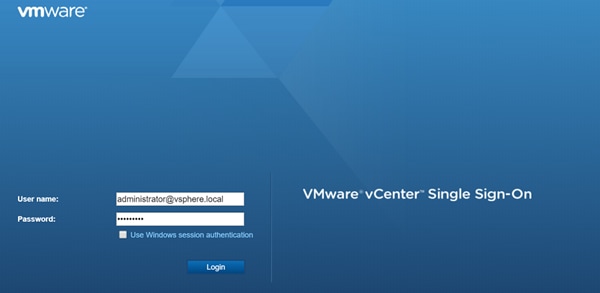
2. From the home page select the Hitachi Storage Plug-in icon.

3. Select Datastores from the navigator pane.
4. Click the Provision Datastore icon to begin provisioning.
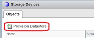
5. From the Provision Datastore wizard select provisioning type as VMFS Datastore, click Next.
6. Select the applicable VMFS version, click Next.
7. Choose the allocation type, define a Datastore name along with capacity, click Next.
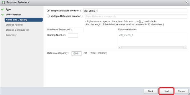
8. Click the applicable datacenter and select the HBAs of your hosts, click Next.
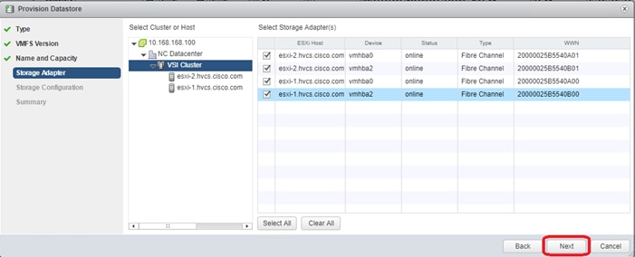
9. For the storage Configuration screen, configure the storage system for the datastore(s):
a. Select Storage System.
b. Select Storage Pool/RAID Group.
c. Select Capacity Saving if you chose VSP F350, F370, F700, F900 or VSP G350, G370, G700, G900
d. Specify a value for LUN ID.(Optional)
e. Select Host Group/Target.
f. Click Next.
10. For the Summary screen, confirm the settings for the datastore. Click a screen name to modify any settings. Click Next.
11. Click Finish. The datastore creation progress and results can be viewed in vSphere Web Client Recent Tasks.
12. Repeat steps 3-11 to allocate additional VMFS datastores.
Allocate VMFS datastore using Hitachi Unified Compute Platform Advisor
You can provision a new Virtual Machine File System (VMFS) datastore to create a logical container for virtual machine files. When creating a datastore, Hitachi Unified Compute Platform (UCP) Advisor automatically creates an associated logical unit on the storage system.
![]() Storage System(s) must be onboarded to UCP Advisor prior to datastore allocation, for information on how to register a storage system refer to the UCP Advisor deployment guide.
Storage System(s) must be onboarded to UCP Advisor prior to datastore allocation, for information on how to register a storage system refer to the UCP Advisor deployment guide.
To begin provisioning a VMFS Datastore using Unified Compute Platform Advisor, follow these steps:
1. Log into VMware vSphere Flex client.
2. From the home page select the UCP Advisor icon.
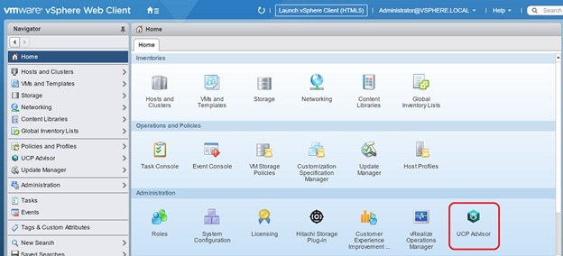
3. Select the registered system within UCP Advisor.
4. From the UCP Advisor menu select Storage.
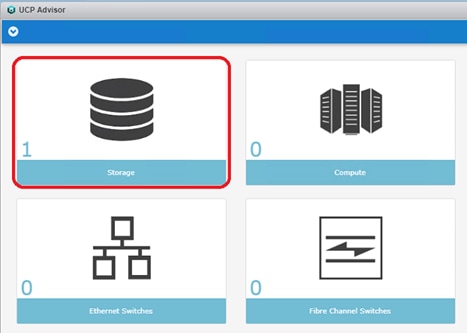
5. From the objects list, double-click your registered storage system to access the Manage tab.
6. From the Manage Tab, select Datastores.
7. Click the Configure Datastore icon.
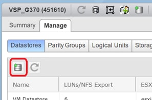
8. From the Configure Datastore wizard select Provision Datastore(s), click Next.
9. Select Datastore Type (VMFS Datastore is currently the only choice), click Next.
10. Select Single Datastore Creation or Multiple Datastore, specify the datastore name and capacity, click Next.
11. Select the appropriate Storage System and Storage Pool from the list, click Next.
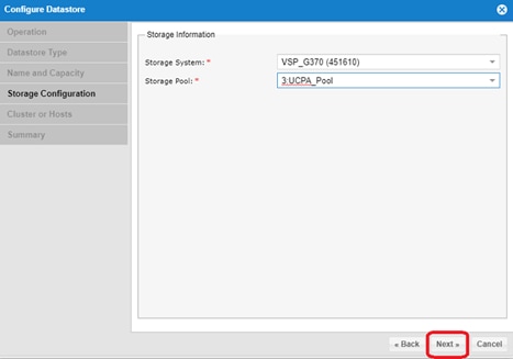
12. Select the ESXi Cluster or Hosts, click Next.
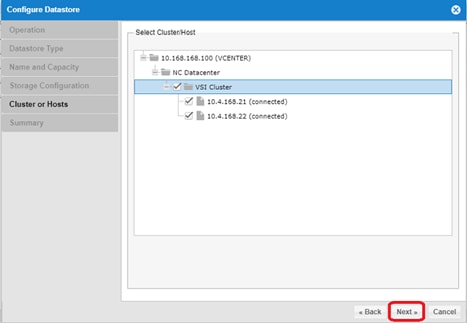
13. Review the settings in the summary window.
14. Click Finish.
Allocate VMFS Datastore using Hitachi Storage Provider for VMware vCenter (LDEV Storage Type)
Hitachi Storage Provider for VMware vCenter allows utilization of SPBM tagging which translates the capabilities of the storage system to the VMware administrator.
The LDEV for allocation must be mapped to your ESXi hosts via the Hitachi Storage Plug-in, UCP Advisor, or Storage Navigator. You must create a storage container and an associated capability profile with the VASA provider. Once complete you must also create a VM storage policy within vSphere which utilizes SPBM tags to correlate storage to its capabilities passed down from the VASA provider.
For detailed information, see the Hitachi Storage Management Software with Cisco UCS for VMware vSphere Best Practices Guide, specifically the sections for Defining a Capability Profile, Defining Virtual Machine Storage Profile (LDEV), and Defining Virtual Machine Storage Profile (LDEV).
To deploy a datastore utilizing SPBM tagging, follow these steps:
1. Log into VMware vSphere Flex client.

2. Navigate to Hosts and Clusters view.
3. From the inventory list select the datacenter where you want to deploy your VMFS datastores.
4. Right-click Storage and select New Datastore.
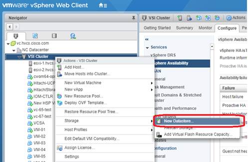
5. In the location screen, click Next.
6. In the Type screen, select VMFS and then click Next.
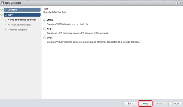
7. In the name and device selection screen, choose your datastore from those listed and click Next.
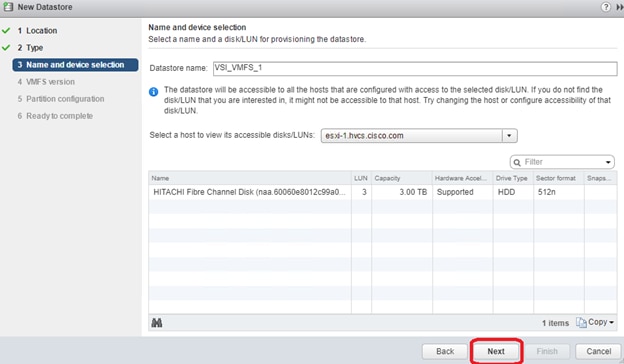
8. Select your VMFS version and partition configuration, click Next.
9. Click Finish to view your new datastore within your storage inventory.
Remediation of L1 Terminal Fault – VMM (L1TF) Security Vulnerability (Optional)
CVE-2018-3646 describes a new class of CPU speculative-execution vulnerabilities on Intel processors manufactured from 2009 to 2018. While optional, it is strongly recommended that these vulnerabilities be patched.
Multiple attack vectors are exposed through these vulnerabilities, and separate mitigation steps for each attack vector are necessary for complete mitigation. More information about the specific impact and VMware’s recommendations for remediation of these vulnerabilities in a VMware vSphere environment can be found at https://kb.vmware.com/s/article/55806.
The mitigation for L1TF-VMM as recommended by VMware is broken up into three distinct phases:
1. Updating VMware vCenter and VMware ESXi software
2. Planning and Utilization of the HTAware Mitigation Tool (if analyzing existing workloads)
3. Enablement of an ESXi Side-Channel-Aware Scheduler
![]() Please be aware that as of April 2019, VMware has introduced a second version of the ESXi Side-Channel-Aware Scheduler (SCAv2), which balances security and performance more than the original Scheduler (SCAv1). An important item to note is that the new Side-Channel-Aware Scheduler does NOT prevent intra-VM Concurrent-Context Attack Vector process information leakage and is only available within ESXi 6.7U2 or later. More information including specific mitigation steps is available at the VMware KB link listed above (55806).
Please be aware that as of April 2019, VMware has introduced a second version of the ESXi Side-Channel-Aware Scheduler (SCAv2), which balances security and performance more than the original Scheduler (SCAv1). An important item to note is that the new Side-Channel-Aware Scheduler does NOT prevent intra-VM Concurrent-Context Attack Vector process information leakage and is only available within ESXi 6.7U2 or later. More information including specific mitigation steps is available at the VMware KB link listed above (55806).
In addition to ACI integrations with vSphere for distributed switch management, the 4.1 release of ACI includes new UCSM integration to handle VLAN configuration within the FI for VLANs allocated through the VMM for the previously existing vSphere integration.
Cisco ACI vCenter Plug-in
The Cisco ACI vCenter plug-in is a user interface that allows you to manage the ACI fabric from within the vSphere Web client. This allows the VMware vSphere Web Client to become a single pane of glass to configure both VMware vCenter and the ACI fabric. The Cisco ACI vCenter plug-in empowers virtualization administrators to define network connectivity independently of the networking team while sharing the same infrastructure. No configuration of in-depth networking is done through the Cisco ACI vCenter plug-in. Only the elements that are relevant to virtualization administrators are exposed.
The vCenter Plug-in is an optional component but will be used in the example application tenant that will be configured.
Cisco ACI vCenter Plug-in Installation
To begin the plug-in installation on a Windows system, follow these steps:
![]() To complete the installation of the ACI vCenter Plug-in, VMware PowerCLI 6.5 Release 1 must be installed on a Windows administration workstation. VMware PowerCLI 6.5 Release 1 can be downloaded from https://my.vmware.com/web/vmware/details?downloadGroup=PCLI650R1&productId=859.
To complete the installation of the ACI vCenter Plug-in, VMware PowerCLI 6.5 Release 1 must be installed on a Windows administration workstation. VMware PowerCLI 6.5 Release 1 can be downloaded from https://my.vmware.com/web/vmware/details?downloadGroup=PCLI650R1&productId=859.
1. Connect to: Connect to: https://<apic-ip>/vcplugin
2. Follow the Installation instructions on that web page to complete plug-in installation.
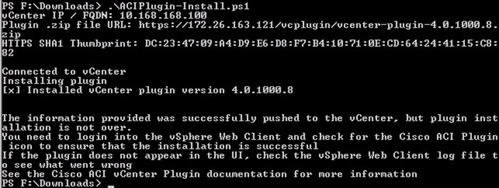
3. From the vSphere Web Client (Flex Client).
4. Select Home ->Administration -> Client Plug-Ins.
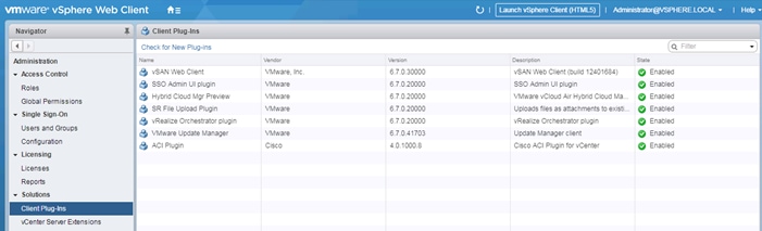
5. Click Check for New Plug-ins if the ACI Plugin does not appear in the Client Plug-Ins list.
6. Log out and log back into the vSphere Client if advised.
7. Within Home, the Cisco ACI Fabric icon should appear.
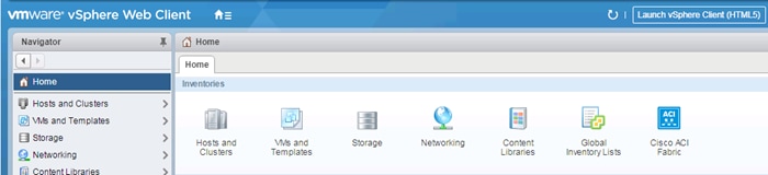
8. Click the Cisco ACI Fabric Icon.
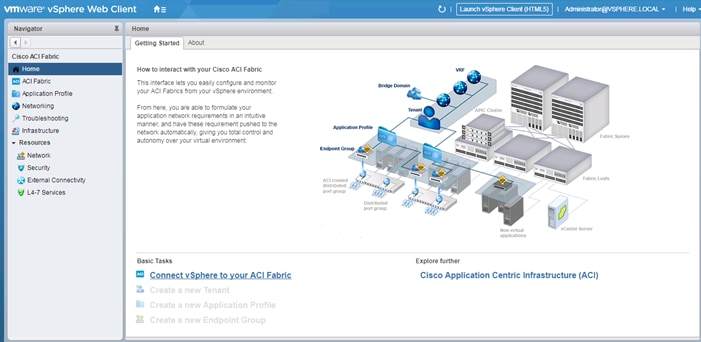
9. In the center pane, select Connect vSphere to your ACI Fabric.
10. Click Yes to add a new ACI Fabric.
11. Enter one APIC IP address or FQDN and uncheck Use Certificate.
12. Enter the admin Username and Password.
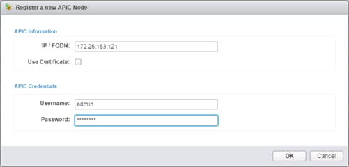
13. Click OK.
14. Click OK to confirm the addition of the other APICs.
Create Virtual Machine Manager (VMM) Domain in APIC
To configure the VMware vSphere VMM integration for managing a vDS within vCenter follow these steps:
1. In the APIC GUI, select Virtual Networking > Inventory.
2. On the left, expand VMM Domains > VMware.
3. Right-click VMware and select Create vCenter Domain.
4. Name the Virtual Switch CHV-vDS. Leave VMware vSphere Distributed Switch selected.
5. Select the CHV-Site1-UCS_AttEntityP Associated Attachable Entity Profile.
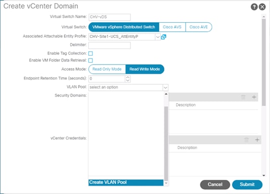
6. Under VLAN Pool, select Create VLAN Pool.
7. Name the VLAN Pool CHV-Application. Leave Dynamic Allocation selected.
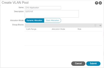
8. Click the “+” to add a block of VLANs to the pool.
9. Enter the VLAN range <1100-1199> and click OK.
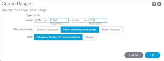
10. Click Submit to complete creating the VLAN Pool.
11. Click the “+” to the right of vCenter Credentials to add credentials for the vCenter.
12. For name, enter the vCenter hostname. Provide the appropriate username and password for the vCenter.
13. Click OK to complete creating the vCenter credentials.
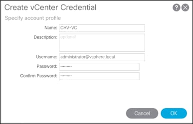
![]() The Administrator account is used in this example, but an APIC account can be created within the vCenter to enable the minimum set of privileges. For more information, see the ACI Virtualization Guide on cisco.com.
The Administrator account is used in this example, but an APIC account can be created within the vCenter to enable the minimum set of privileges. For more information, see the ACI Virtualization Guide on cisco.com.
14. Click the “+” to the right of vCenter to add the vCenter linkage.
15. Enter the vCenter hostname for Name. Enter the vCenter FQDN or IP address.
16. Leave vCenter Default for the DVS Version.
17. Enable Stats Collection.
18. For Datacenter, enter the exact Datacenter name specified in vCenter.
19. Do not select a Management EPG.
20. For Associated Credential, select the vCenter credentials entered in step 13.
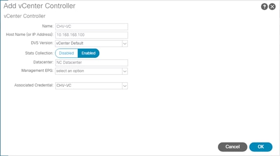
21. Click OK to complete the vCenter linkage.
22. For Port Channel Mode, select MAC Pinning-Physical-NIC-load.
23. For vSwitch Policy, select LLDP.
24. Leave NetFlow Exporter Policy unconfigured.
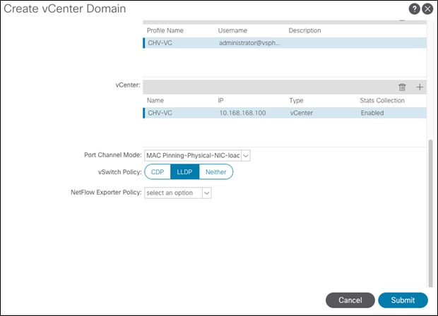
25. Click Submit to complete Creating the vCenter Domain.
![]() The vDS should now appear in vCenter.
The vDS should now appear in vCenter.
Add UCS Hosts to the vDS
To add the UCS hosts to the provisioned vDS, follow these steps:
1. Connect to the vSphere Web Client for the vCenter.
2. Select the Networking tab within Navigator and navigate into the configured datacenter and select the provisioned vDS.
3. Click Add and manage hosts.
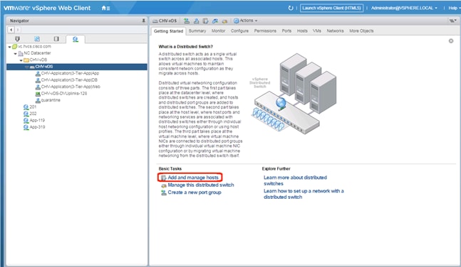
4. Leave Add hosts selected and click Next.
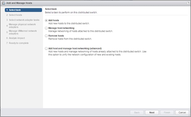
5. Click the + New hosts… option.
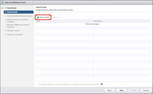
6. Select the installed hosts and click OK.
7. Click Next.
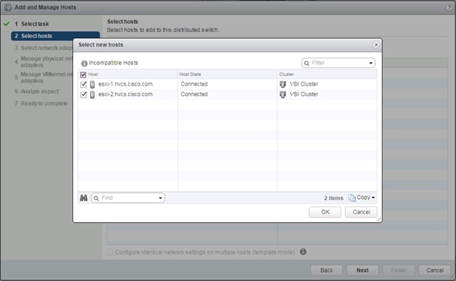
8. Unselect Manage VMkernel adapters, and leave Migrate virtual machine networking unselected.
9. Click Next.
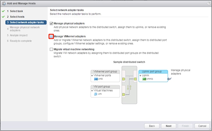
10. Click Assign uplink and select vmnic2 for the first host
11. Click Next.
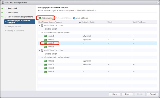
12. Leave uplink1 selected and click OK.
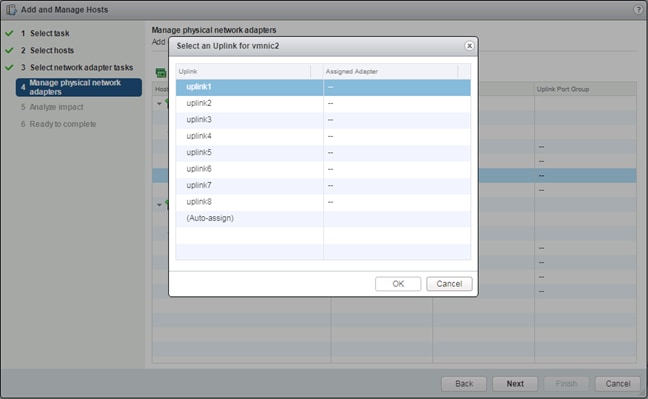
13. Select vmnic3 and click Assign uplink.
14. Click Next.
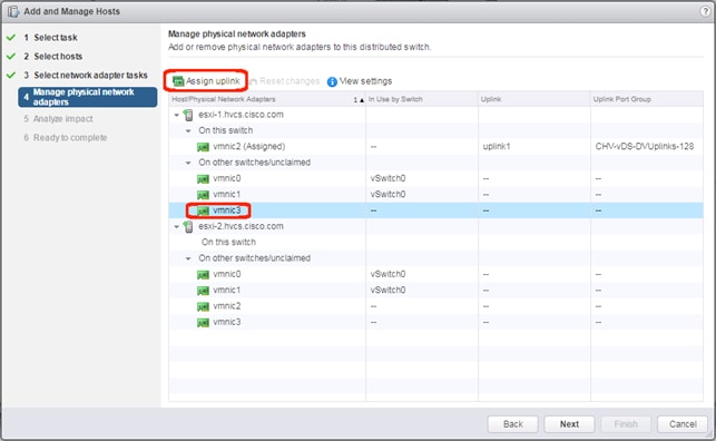
15. Leave uplink2 selected and click OK.
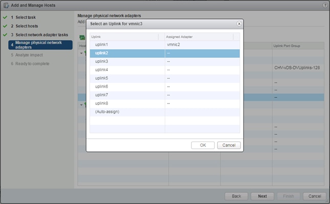
16. Repeat steps 10-13 for all additional hosts.
17. Click Next.
18. Click Next past Impact Analysis.
19. Review the Ready to complete page and click Finish to add the hosts.
Cisco UCS Manager Integration
The ACI UCS Integration will automatically configure the dynamic VLANs allocated to port groups associated with the vDS VMM on both the UCS FI uplinks and vNIC Templates associated with the vDS vNICs.
To configure the ACI UCS Integration, perform the following steps:
Install the ExternalSwitch App to the APIC
The Cisco External Switch Manager backend app provides connectivity between the APIC and the UCS FI as switches external to the ACI fabric. Installing this app is required before the integration can communicate between these components.
To install the ExternalSwitch App to the APIC, follow these steps:
1. Download the Cisco-ExternalSwitch-1.0.aci app from https://dcappcenter.cisco.com/externalswitch-4-1-1a-1-0-258.html
2. Within the APIC GUI, select the Apps tab.
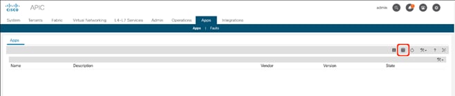
3. Click the Add Application icon.
4. Click Browse and select the downloaded .aci file for the ExternalSwitch App.
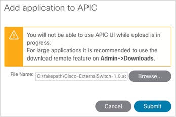
5. Click Submit.
6. Select the installed application.
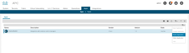
7. Right-click the options icon and click Enable Application option.
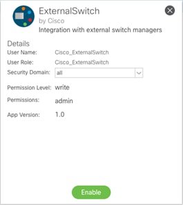
8. Click Enable.
Create and Configure an Integration Group
To configure the Cisco UCS Manager Integration within the APIC, follow these steps:
1. In the APIC GUI, select Integrations > Create Group.
2. Provide the Integration Group with a name.
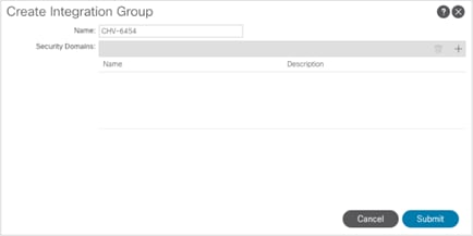
3. Click Submit.
4. Double-click the previously created Integration Group. [CHV-6454]
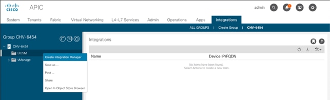
5. Right-click the UCSM folder and select the Create Integration Manager option.
6. Provide the following information to the pop-up window that appears:
7. Name – name to reference the UCSM
8. Device IP/FQDN – address of the UCSM
9. Username – login to use for the UCSM
10. Password – password to provide for the specified Username
11. Leave Deployment Policy and Preserve NIC Profile Config settings as defaults.

12. Click Submit.
Add the Cisco UCS Manager Integration as a VMM Switch Manager
To configure the Cisco UCS Manager Integration with the APIC to propagate the VLAN associations occurring within the VMM, follow these steps:
1. Connect to Virtual Networking -> Inventory within the APIC GUI.
2. Select VMM Domains -> VMware -> [CHV-vDS] -> Controllers -> CHV-VC within the Inventory.
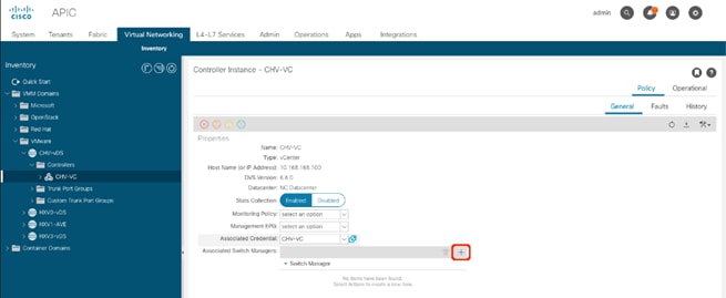
3. Click the + icon to the right side of the Associated Switch Managers bar.
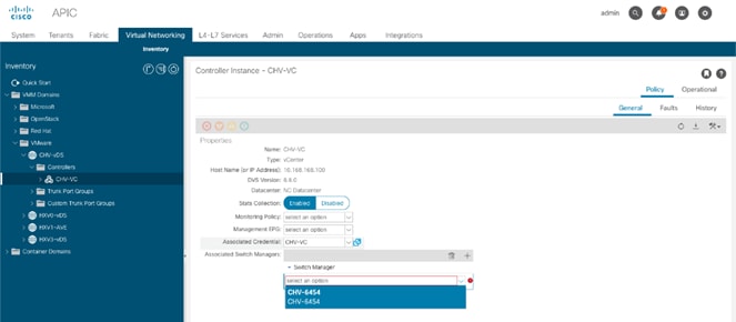
4. Select the configured UCSM Integration [CHV-6454/CHV-6454].
5. Click Update.
Create an Application Tenant with the Cisco ACI vCenter Plugin
With the vCenter Plugin in place, a tenant and application EPGs can be created directly from the vCenter. To begin, follow these steps:
1. Open up the vSphere Web Client connection to the vCenter with the Flex Client.
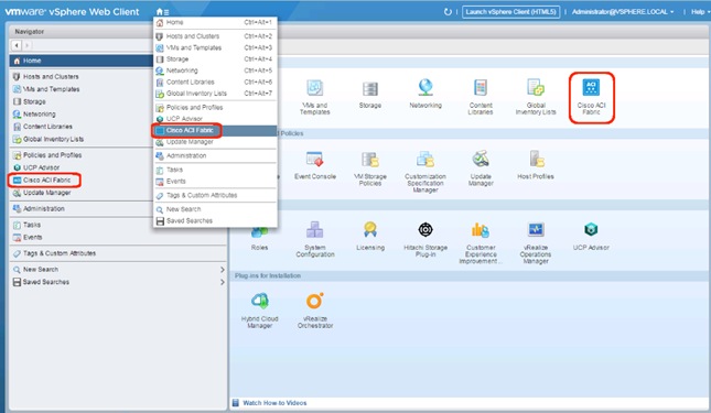
2. Open up the Cisco ACI Fabric icon.
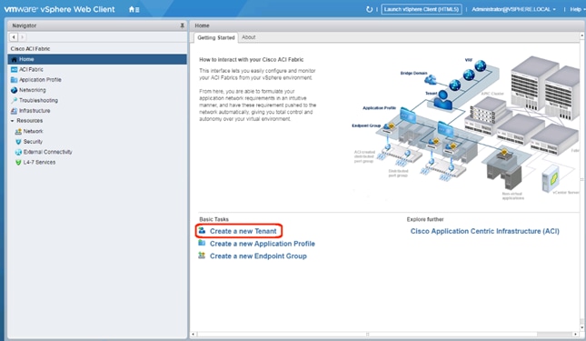
3. Click Create a new Tenant under Basic Tasks.
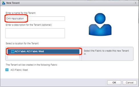
4. Provide a name for the Tenant and select the Fabric it will be created within.
5. Click OK.
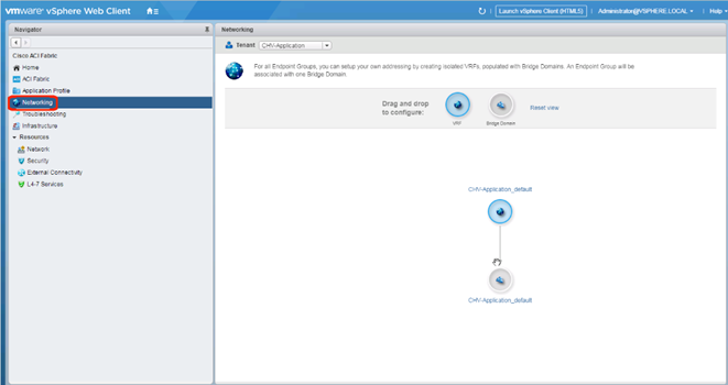
6. Click Networking within the Cisco ACI Fabric options of Navigator.
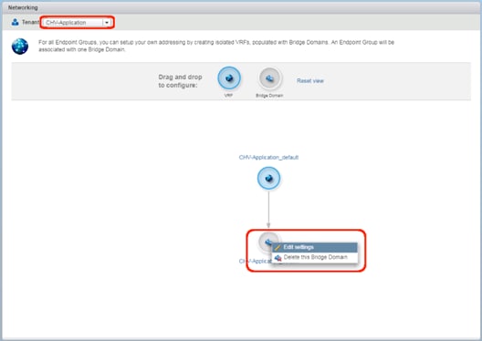
7. Confirm that the correct Tenant is selected, and right-click the Bridge Domain that was created with the VRF when the Tenant was formed and select the Edit settings option.
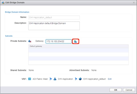
8. Enter a subnet gateway to use for the bridge domain, along with the CIDR / notation for the subnet mask to use. Click the cloud icon to the right of the Gateway field to apply the subnet and the gateway.
![]() In this application example, the subnet is 172.18.100.0/22 and will be shared by all of the application EPGs that will have distinct connectivity rules applied to them via contracts despite existing within the same subnet. If dedicated subnets are preferred for each EPG, dedicated bridge domains should be defined here with the respective subnets to associate with the application EPGs.
In this application example, the subnet is 172.18.100.0/22 and will be shared by all of the application EPGs that will have distinct connectivity rules applied to them via contracts despite existing within the same subnet. If dedicated subnets are preferred for each EPG, dedicated bridge domains should be defined here with the respective subnets to associate with the application EPGs.
9. Click OK.
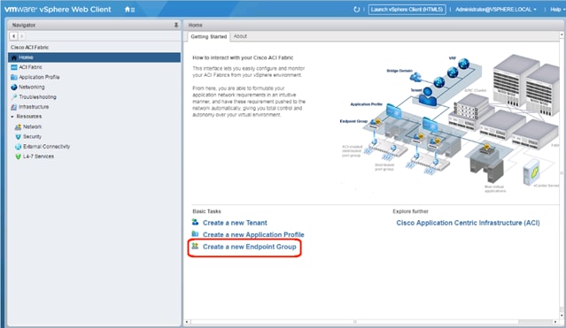
10. Click Create a new Endpoint Group under Basic Tasks.
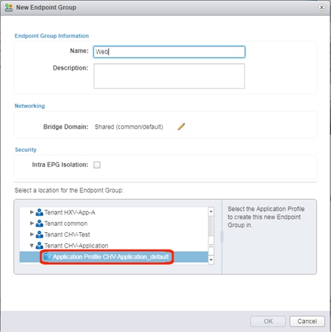
11. Specify a Name for the Endpoint Group, select the Tenant [CHV-Application] and Application Profile [CHV-Application_default] to create the EPG in.
12. Click the pencil icon next to Bridge Domain.
13. Expand the Tenant and VRF to select the Bridge Domain that was created for this tenant.
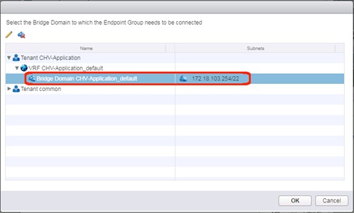
14. Click OK.
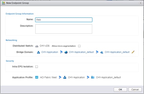
15. Click OK.
16. Repeat steps 9-14 to create additional EPGs [App and DB].
![]() The following will create a contract from the App EPG to connect to both the Web and DB EPGs without Web and DB being able to communicate with each other.
The following will create a contract from the App EPG to connect to both the Web and DB EPGs without Web and DB being able to communicate with each other.
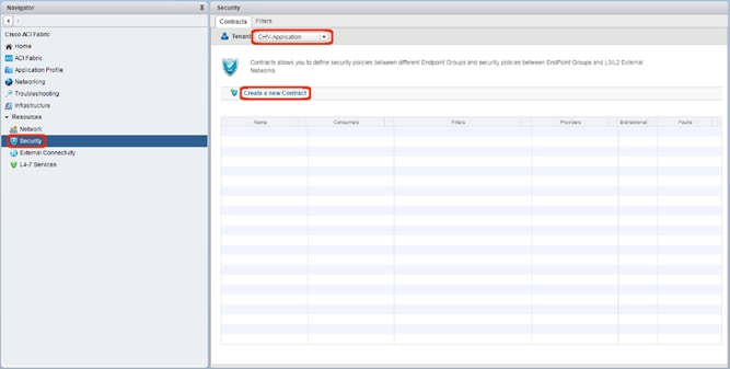
17. Click the Security option, confirm that the correct Tenant is selected, and click Create a new Contract.
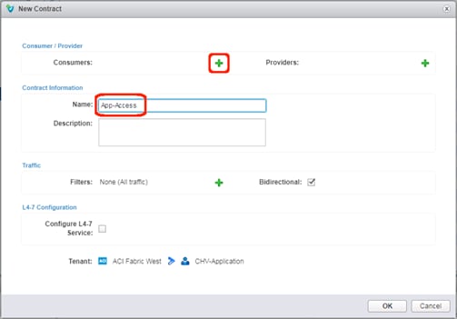
18. Provide a name for the Contract to allow traffic from the App EPG to the other two members. Click the green + icon to the right of Consumers.
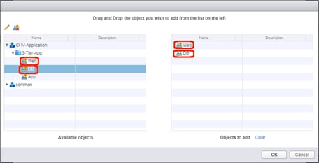
19. Select the Web and DB EPGs from within the 3-Tier-App and drag each over to the right side. Click OK.
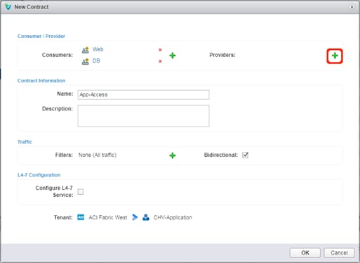
20. Click the green + icon to the right of Providers.
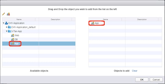
21. Select the App EPG from within the 3-Tier-App and drag it over to the right side. Click OK.
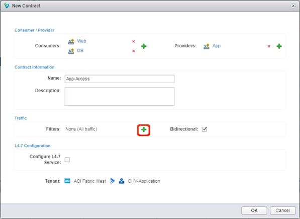
22. Click the green + icon next to Filters.
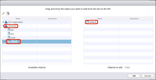
23. Expand the common tenant, select the default contract object and drag it to the right side. Click OK.
![]() The default filter will allow all traffic and may be too permissive for a production environment. Alternately, select the tenant and select the Create a new filter icon next to the pencil to create a set of granular port and protocol specific filters for appropriate traffic between the EPGs.
The default filter will allow all traffic and may be too permissive for a production environment. Alternately, select the tenant and select the Create a new filter icon next to the pencil to create a set of granular port and protocol specific filters for appropriate traffic between the EPGs.
24. Click OK to create the contract from App to the Web and DB EPGs.
Add External Connectivity to Appropriate EPGs
The Allow-Shared-L3-Out contract that was previously created can be associated to EPGs that will need to have access to appropriate external networks. For this contract to be applied, or to grant these EPGs access to contracts from other tenants, the Bridge Domain will need to be changed from the default setting of Private to VRF that is set when a Bridge Domain is created in the vCenter ACI Plugin.
To make this change, follow these steps:
1. Connect to the APIC GUI.
2. Select the Tenants tab and expand within the application tenant: Networking -> Bridge Domains -> <Bridge Domain used> -> Subnets.
3. Select the subnet created for the Bridge Domain.
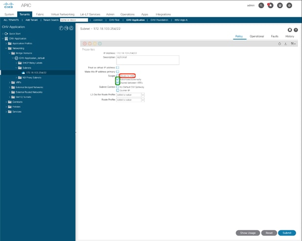
4. Unselect “Private to VRF”
5. Select the check boxes for “Advertised Externally” and “Shared between VRFs”.
6. Click Submit.
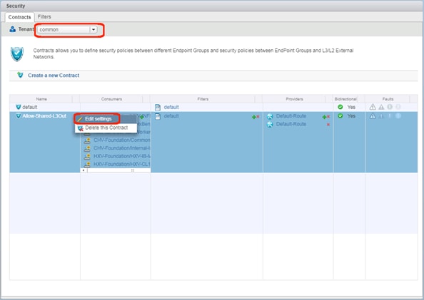
7. Change the Tenant to common within the Contracts tab of Security. Right-click the Allow-Shared-L3Out contract and select the Edit settings option.
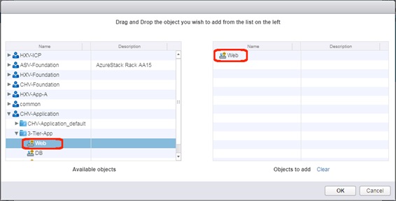
8. Expand the appropriate application tenant and contained application profile. Select any EPG that should be set up to have external connectivity and drag those EPGs over to the right. Click OK.
9. Click OK to make changes to the Allow-Shared-L3Out contract.
Appendix: Bill of Materials
This CVD is directed at deploying the Cisco and Hitachi Adaptive Solutions CI into an existing ACI Fabric, and as a result the initial configuration of the ACI APICs and Spines are out of the scope of the deployment guide and the BOM. Any interest in deploying an initial ACI Fabric should be directed toward a Cisco account manager or partner.
Please note that the following are not included in the BOMs below and will need to be identified separately depending on your specific configuration:
· Racks for both Cisco and Hitachi components
· Power distribution units (PDUs)
· Multi-mode Fibre (MMF) cabling between Cisco Fabric Interconnects and Cisco MDS switches
· Multi-mode Fibre (MMF) cabling between Cisco MDS switches and Hitachi VSP storage systems
· Power cables and rail kits for Hitachi VSP storage systems
· Services, Maintenance, and Support plans for each component
![]() The BOMs below are representative of the equipment used in Cisco Systems lab environments to certify each design. Components, interconnect cabling, and quantities may differ depending on your specific configuration needs. It is important to note that any component changes must be referenced against both Cisco and Hitachi compatibility matrices to ensure proper support is available.
The BOMs below are representative of the equipment used in Cisco Systems lab environments to certify each design. Components, interconnect cabling, and quantities may differ depending on your specific configuration needs. It is important to note that any component changes must be referenced against both Cisco and Hitachi compatibility matrices to ensure proper support is available.
Table 32 lists the BOM for Cisco UCS 6454 Fabric Interconnect with Hitachi VSP G370 with ACI design.
Table 32 Bill of Materials for Cisco 6454 and Hitachi VSP G370 with ACI Design
| Vendor |
Part Number/Order Code |
Description |
Quantity |
| Cisco |
N9K-C93180YC-FX |
Nexus 9300 with 48p 10/25G SFP+, 6p 100G QSFP, MACsec, UP |
2 |
| Cisco |
ACI-N9KDK9-14.1.2 |
Nexus 9500 or 9300 ACI Base Software NX-OS Rel 14.1.2 |
2 |
| Cisco |
N3K-C3064-ACC-KIT |
Nexus 3K/9K Fixed Accessory Kit |
2 |
| Cisco |
NXA-PAC-1100W-PE2 |
Nexus AC 1100W PSU - Port Side Exhaust |
4 |
| Cisco |
NXA-FAN-65CFM-PE |
Nexus Fan, 65CFM, port side exhaust airflow |
6 |
| Cisco |
CAB-9K12A-NA |
Power Cord, 125VAC 13A NEMA 5-15 Plug, North America |
4 |
| Cisco |
QSFP-100G-AOC1M |
100GBASE QSFP Active Optical Cable, 1m |
4 |
| Cisco |
QSFP-40G-SR-BD |
QSFP40G BiDi Short-reach Transceiver |
4 |
| Cisco |
QSFP-H40G-CU1M |
40GBASE-CR4 Passive Copper Cable, 1m |
2 |
| Cisco |
UCS-FI-6454-U |
UCS Fabric Interconnect 6454 |
2 |
| Cisco |
N10-MGT016 |
UCS Manager v4.0 |
2 |
| Cisco |
UCS-ACC-6332 |
UCS 6332/ 6454 Chassis Accessory Kit |
2 |
| Cisco |
UCS-FAN-6332 |
UCS 6332/ 6454 Fan Module |
8 |
| Cisco |
UCS-PSU-6332-AC |
UCS 6332 Power Supply/100-240VAC |
4 |
| Cisco |
CAB-9K12A-NA |
Power Cord, 125VAC 13A NEMA 5-15 Plug, North America |
4 |
| Cisco |
SFP-H10GB-CU2-5M |
10GBASE-CU SFP+ Cable 2.5 Meter |
8 |
| Cisco |
UCSB-5108-AC2-UPG |
UCS 5108 Blade Server AC2 Chassis/0 PSU/8 fans/0 FEX |
1 |
| Cisco |
N20-FW016 |
UCS 5108 Blade Chassis FW Package 4.0 |
1 |
| Cisco |
N20-FAN5 |
Fan module for UCS 5108 |
8 |
| Cisco |
N01-UAC1 |
Single phase AC power module for UCS 5108 |
1 |
| Cisco |
N20-CBLKB1 |
Blade slot blanking panel for UCS 5108/single slot |
4 |
| Cisco |
N20-CAK |
Accessory kit for UCS 5108 Blade Server Chassis |
1 |
| Cisco |
UCSB-B200-M5 |
UCS B200 M5 Blade w/o CPU, mem, HDD, mezz |
4 |
| Cisco |
UCS-CPU-6140 |
2.3 GHz 6140/140W 18C/24.75MB Cache/DDR4 2666MHz |
8 |
| Cisco |
UCSB-MLOM-40G-04 |
Cisco UCS VIC 1440 modular LOM for Blade Servers |
4 |
| Cisco |
UCS-SID-INFR-OI |
Other Infrastructure |
4 |
| Cisco |
UCSB-HS-M5-R |
CPU Heat Sink for UCS B-Series M5 CPU socket (Rear) |
4 |
| Cisco |
UCSB-LSTOR-BK |
FlexStorage blanking panels w/o controller, w/o drive bays |
8 |
| Cisco |
UCSB-HS-M5-F |
CPU Heat Sink for UCS B-Series M5 CPU socket (Front) |
4 |
| Cisco |
UCS-SID-WKL-OW |
Other Workload |
4 |
| Cisco |
UCS-IOM-2208XP |
UCS 2208XP I/O Module (8 External, 32 Internal 10Gb Ports) |
2 |
| Cisco |
UCSB-PSU-2500ACDV |
2500W Platinum AC Hot Plug Power Supply - DV |
4 |
| Cisco |
UCSB-5108-PKG-HW |
UCS 5108 Packaging for chassis with half width blades. |
1 |
| Cisco |
CAB-US515P-C19-US |
NEMA 5-15 to IEC-C19 13ft US |
4 |
| Cisco |
UCS-MR-X32G2RS-H |
32GB DDR4-2666-MHz RDIMM/PC4-21300/dual rank/x4/1.2v |
48 |
| Cisco |
UCS-DIMM-BLK |
UCS DIMM Blanks |
48 |
| Cisco |
DS-C9706 |
MDS 9706 Chassis No Power Supplies, Fans Included |
2 |
| Cisco |
DS-X9706-FAB1 |
MDS 9706 Crossbar Switching Fabric-1 Module |
12 |
| Cisco |
DS-9706-KIT-CCO |
MDS 9706 Accessory Kit for Cisco |
2 |
| Cisco |
DS-C9700-LC-BL |
Blank Filler Card for Line Card slot in MDS9700 Chassis |
6 |
| Cisco |
DS-X97-SF1-K9 |
MDS 9700 Series Supervisor-1 |
4 |
| Cisco |
DS-X9648-1536K9 |
MDS 9700 48-Port 32-Gbps Fibre Channel Switching Module |
2 |
| Cisco |
DS-CAC97-3KW |
MDS 9700 3000W AC power supply |
8 |
| Cisco |
M97S3K9-8.2.1 |
MDS 9700 Supervisor/Fabric-3, NX-OS Software Release 8.2(1) |
2 |
| Cisco |
CAB-9K16A-US2 |
Power Cord 250VAC 16A, US/Japan, Src Plug NEMA L6-20 |
8 |
| Cisco |
DS-SFP-FC32G-SW |
32 Gbps Fibre Channel SW SFP+, LC |
12 |
| Hitachi |
VSP-G-SOLUTION.S |
VSP G Unified Platform |
1 |
| Hitachi |
VSP-G370-A0008.S |
VSP G370 Covered Product Unified (FC/iSCSI) |
1 |
| Hitachi |
G370-F-BASE-S.P |
VSP G370 Foundation Base Package |
1 |
| Hitachi |
GXX0-4X1R9TB.P |
VSP GXX0 Flash Pack 4 x 1.9TB SSD Package |
12 |
| Hitachi |
VSP-G370-A0001.S |
VSP G370 Product Unified (FC/iSCSI) |
1 |
| Hitachi |
FD221577-001.P |
SVP Bezel ASM (including brackets) |
1 |
| Hitachi |
HDW2-F850-1PS32.P |
VSP G SFP for 32Gbps Shortwave |
16 |
| Hitachi |
HDW2-F850-DBSC.P |
VSP G/F XX0 Drive Box (SFF) |
1 |
| Hitachi |
HDW-F850-SCQ1.P |
VSP G SAS Cable 1m |
2 |
| Hitachi |
HDW2-F850-SVP.P |
VSP G/FXX0 SVP - Service Processor |
1 |
| Hitachi |
HDW2-F850-4HF32R.P |
VSP G/FXX0 Host I/O Module FC 16/32G 4port |
4 |
Create Device Aliases
Using the WWPN target and initiator table created earlier in Table 33 collect the information for the device aliases to be created on each fabric:
Table 33 Fabric A Targets and Initiators
|
|
Name |
pWWN/WWPN Example Environment (Port Name) |
pWWN/WWPN Customer Environment |
| Target |
G370-CL1-A |
50:06:0e:80:12:c9:9a:00 |
|
| Target |
G370-CL2-B |
50:06:0e:80:12:c9:9a:11 |
|
| Initiator |
VSI-G370-01 |
20:00:00:25:B5:54:0A:00 |
|
| Initiator |
VSI-G370-02 |
20:00:00:25:B5:54:0A:01 |
|
Table 34 Table 1 Fabric B Targets and Initiators
|
|
|
pWWN/WWPN Example Environment (Port Name) |
pWWN/WWPN Customer Environment |
| Target |
G370-CL3-B |
50:06:0e:80:12:c9:9a:21 |
|
| Target |
G370-CL4-A |
50:06:0e:80:12:c9:9a:30 |
|
| Initiator |
VSI-G370-01 |
20:00:00:25:B5:54:0B:00 |
|
| Initiator |
VSI-G370-02 |
20:00:00:25:B5:54:0B:01 |
|
With the appropriate information collected, proceed to create device aliases on the MDS fabrics using the following as an example:
Fabric A Device Aliases
aa19-9706-1(config)# device-alias database
aa19-9706-1(config-device-alias-db)# device-alias name VSI-G370-1 pwwn 20:00:00:25:B5:54:0A:00
aa19-9706-1(config-device-alias-db)# device-alias name VSI-G370-2 pwwn 20:00:00:25:B5:54:0A:01
aa19-9706-1(config-device-alias-db)# device-alias name G370-CL1-A pwwn 50:06:0E:80:12:C9:9A:00
aa19-9706-1(config-device-alias-db)# device-alias name G370-CL2-B pwwn 50:06:0E:80:12:C9:9A:11
aa19-9706-1(config-device-alias-db)# exit
aa19-9706-1(config)# device-alias commit
Fabric B Device Aliases
aa19-9706-2(config)# device-alias database
aa19-9706-2(config-device-alias-db)# device-alias name VSI-G370-1 pwwn 20:00:00:25:B5:54:0B:00
aa19-9706-2(config-device-alias-db)# device-alias name VSI-G370-2 pwwn 20:00:00:25:B5:54:0B:01
aa19-9706-2(config-device-alias-db)# device-alias name G370-CL3-B pwwn 50:06:0E:80:12:C9:9A:21
aa19-9706-2(config-device-alias-db)# device-alias name G370-CL4-A pwwn 50:06:0E:80:12:C9:9A:30
aa19-9706-2(config-device-alias-db)# exit
aa19-9706-2(config)# device-alias commit
Create Zoning
With device alias created, the following will occur on each fabric in this example:
· Smart-zoning will be set for the fabric
· Zones for each host to initiator targets will be created
· A zoneset will be created
· Created zones will be added to the zone
· The zoneset will be activated
· The configuration will be saved to allow the device aliases and the zoning to persist on each fabric
Fabric A Zoning
aa19-9706-1(config)# zone smart-zoning enable vsan 101
Smart Zoning distribution initiated. check zone status
aa19-9706-1(config)# zone name VSI-FC-G370-1 vsan 101
aa19-9706-1(config-zone)# member device-alias VSI-FC-G370-1 init
aa19-9706-1(config-zone)# member device-alias G370-CL1-A target
aa19-9706-1(config-zone)# member device-alias G370-CL1-B target
aa19-9706-1(config-zone)# member device-alias G370-CL2-A target
aa19-9706-1(config-zone)# member device-alias G370-CL2-B target
aa19-9706-1(config-zone)# zone name VSI-FC-G370-2 vsan 101
aa19-9706-1(config-zone)# member device-alias VSI-FC-G370-2 init
aa19-9706-1(config-zone)# member device-alias G370-CL1-A target
aa19-9706-1(config-zone)# member device-alias G370-CL1-B target
aa19-9706-1(config-zone)# member device-alias G370-CL2-A target
aa19-9706-1(config-zone)# member device-alias G370-CL2-B target
aa19-9706-1(config-zone)# zoneset name ucp-vsi-zoneset vsan 101
aa19-9706-1(config-zoneset)# member VSI-FC-G370-1
aa19-9706-1(config-zoneset)# member VSI-FC-G370-2
aa19-9706-1(config-zoneset)# exit
aa19-9706-1(config)# zoneset activate name ucp-vsi-zoneset vsan 101
Zoneset activation initiated. check zone status
aa19-9706-1(config)# copy run start
[########################################] 100%
Copy complete.
Fabric B Zoning
aa19-9706-2(config)# zone smart-zoning enable vsan 102
Smart Zoning distribution initiated. check zone status
aa19-9706-2(config)# zone name VSI-FC-G370-1 vsan 102
aa19-9706-2(config-zone)# member device-alias VSI-FC-G370-1 init
aa19-9706-2(config-zone)# member device-alias G370-CL3-A target
aa19-9706-2(config-zone)# member device-alias G370-CL3-B target
aa19-9706-2(config-zone)# member device-alias G370-CL4-A target
aa19-9706-2(config-zone)# member device-alias G370-CL4-B target
aa19-9706-2(config-zone)# zone name VSI-FC-G370-2 vsan 102
aa19-9706-2(config-zone)# member device-alias G370-CL3-A target
aa19-9706-2(config-zone)# member device-alias G370-CL3-B target
aa19-9706-2(config-zone)# member device-alias G370-CL4-A target
aa19-9706-2(config-zone)# member device-alias G370-CL4-B target
aa19-9706-2(config-zone)# zoneset name ucp-vsi-zoneset vsan 102
aa19-9706-2(config-zoneset)# member VSI-FC-G370-1
aa19-9706-2(config-zoneset)# member VSI-FC-G370-2
aa19-9706-2(config-zoneset)# zoneset activate name ucp-vsi-zoneset vsan 102
Zoneset activation initiated. check zone status
aa19-9706-2(config)# copy run start
[########################################] 100%
Copy complete.
MDS A Configuration
![]() MDS B is identical to MDS A, except that VSAN is used. An example wwn/pwwn is shown below.
MDS B is identical to MDS A, except that VSAN is used. An example wwn/pwwn is shown below.
version 8.3(1)
power redundancy-mode ps-redundant
power redundancy-mode ps-redundant
feature npiv
feature fport-channel-trunk
feature lldp
role name default-role
description This is a system defined role and applies to all users.
rule 5 permit show feature environment
rule 4 permit show feature hardware
rule 3 permit show feature module
rule 2 permit show feature snmp
rule 1 permit show feature system
username admin password 5 $5$ZUTjKo32$/.kdz66FvCWJctfVT0cQwlBqHzKkIhWrIc86gXv6aX8 role network-admin
ip domain-lookup
ip host AA19-9706-1 192.168.168.18
aaa group server radius radius
class-map type qos match-all copp-s-selfIp
snmp-server user admin network-admin auth md5 0x267983550d7062ba68d3e8acb81bb136 priv 0x267983550d7062ba68d3e8acb81bb136 localizedkey
snmp-server host 10.1.168.101 traps version 2c public udp-port 2162
rmon event 1 log trap public description FATAL(1) owner PMON@FATAL
rmon event 2 log trap public description CRITICAL(2) owner PMON@CRITICAL
rmon event 3 log trap public description ERROR(3) owner PMON@ERROR
rmon event 4 log trap public description WARNING(4) owner PMON@WARNING
rmon event 5 log trap public description INFORMATION(5) owner PMON@INFO
ntp server 192.168.168.254
vlan 1
vlan 1
vsan database
vsan 101 name "Fabric-A"
device-alias mode enhanced
device-alias database
device-alias name G370-CL1-A pwwn 50:06:0e:80:12:c9:9a:00
device-alias name G370-CL1-B pwwn 50:06:0e:80:12:c9:9a:01
device-alias name G370-CL2-A pwwn 50:06:0e:80:12:c9:9a:10
device-alias name G370-CL2-B pwwn 50:06:0e:80:12:c9:9a:11
device-alias name VSI-FC-G370-1 pwwn 20:00:00:25:b5:54:0a:00
device-alias name VSI-FC-G370-2 pwwn 20:00:00:25:b5:54:0a:01
device-alias name VSI-FC-G370-3 pwwn 20:00:00:25:b5:54:0a:02
device-alias name VSI-FC-G370-4 pwwn 20:00:00:25:b5:54:0a:03
device-alias commit
fcdomain fcid database
vsan 101 wwn 50:06:0e:80:12:c9:9a:01 fcid 0xbc0080 dynamic
! [G370-CL1-B]
vsan 101 wwn 50:06:0e:80:12:c9:9a:11 fcid 0xbc00c0 dynamic
! [G370-CL2-B]
vsan 101 wwn 50:06:0e:80:12:c9:9a:10 fcid 0xbc00e0 dynamic
! [G370-CL2-A]
vsan 101 wwn 50:06:0e:80:12:c9:9a:00 fcid 0xbc0160 dynamic
! [G370-CL1-A]
vsan 101 wwn 24:01:00:de:fb:d6:3b:40 fcid 0xbc0180 dynamic
vsan 101 wwn 24:01:00:de:fb:ff:fe:00 fcid 0xbc01a0 dynamic
vsan 101 wwn 20:00:00:25:b5:54:0a:00 fcid 0xbc01a1 dynamic
! [VSI-FC-G370-1]
vsan 101 wwn 20:00:00:25:b5:54:0a:01 fcid 0xbc01a2 dynamic
! [VSI-FC-G370-2]
vsan 101 wwn 20:00:00:25:b5:54:0a:03 fcid 0xbc01a3 dynamic
! [VSI-FC-G370-4]
vsan 101 wwn 20:00:00:25:b5:54:0a:02 fcid 0xbc01a4 dynamic
! [VSI-FC-G370-3]
zone smart-zoning enable vsan 101
!Active Zone Database Section for vsan 101
zone name VSI-FC-G370-1 vsan 101
member device-alias VSI-FC-G370-1 init
member device-alias G370-CL1-A target
member device-alias G370-CL1-B target
member device-alias G370-CL2-A target
member device-alias G370-CL2-B target
zone name VSI-FC-G370-2 vsan 101
member device-alias VSI-FC-G370-2 init
member device-alias G370-CL1-A target
member device-alias G370-CL1-B target
member device-alias G370-CL2-A target
member device-alias G370-CL2-B target
zone name VSI-FC-G370-3 vsan 101
member device-alias VSI-FC-G370-3 init
member device-alias G370-CL1-A target
member device-alias G370-CL1-B target
member device-alias G370-CL2-A target
member device-alias G370-CL2-B target
zone name VSI-FC-G370-4 vsan 101
member device-alias VSI-FC-G370-4 init
member device-alias G370-CL1-A target
member device-alias G370-CL1-B target
member device-alias G370-CL2-A target
member device-alias G370-CL2-B target
zoneset name hvcs-vsi-zoneset vsan 101
member VSI-FC-G370-1
member VSI-FC-G370-2
member VSI-FC-G370-3
member VSI-FC-G370-4
zoneset activate name hvcs-vsi-zoneset vsan 101
do clear zone database vsan 101
!Full Zone Database Section for vsan 101
zoneset name hvcs-vsi-zoneset vsan 101
interface mgmt0
ip address 192.168.168.18 255.255.255.0
interface port-channel15
channel mode active
switchport description UCS-6454-portchannel
switchport speed auto max 32000
switchport rate-mode dedicated
vsan database
vsan 101 interface port-channel15
vsan 101 interface fc1/11
vsan 101 interface fc1/12
vsan 101 interface fc1/13
vsan 101 interface fc1/14
vsan 101 interface fc1/15
vsan 101 interface fc1/16
vsan 101 interface fc1/17
vsan 101 interface fc1/18
interface fc1/1
no shutdown
interface fc1/2
no shutdown
interface fc1/3
no shutdown
interface fc1/4
no shutdown
interface fc1/5
switchport description UCS-6454-A:1/1
channel-group 15 force
no shutdown
interface fc1/6
switchport description UCS-6454-A:1/2
channel-group 15 force
no shutdown
interface fc1/7
no shutdown
interface fc1/8
no shutdown
interface fc1/9
no shutdown
interface fc1/10
no shutdown
interface fc1/11
switchport description G370-A:CL 1-A
no shutdown
interface fc1/12
switchport description G370-A:CL 2-B
no shutdown
interface fc1/13
no shutdown
interface fc1/14
no shutdown
interface fc1/15
no shutdown
interface fc1/16
no shutdown
interface fc1/17
no shutdown
interface fc1/18
no shutdown
interface fc1/19
interface fc1/20
interface fc1/21
interface fc1/22
interface fc1/23
interface fc1/24
interface fc1/25
interface fc1/26
interface fc1/27
interface fc1/28
interface fc1/29
interface fc1/30
interface fc1/31
interface fc1/32
interface fc1/33
interface fc1/34
interface fc1/35
interface fc1/36
interface fc1/37
interface fc1/38
interface fc1/39
interface fc1/40
interface fc1/41
interface fc1/42
interface fc1/43
interface fc1/44
interface fc1/45
interface fc1/46
interface fc1/47
interface fc1/48
clock timezone EST 0 0
switchname AA19-9706-1
line console
line vty
interface fc1/2
interface fc1/3
interface fc1/4
interface fc1/6
interface fc1/1
interface fc1/5
interface fc1/7
interface fc1/8
interface fc1/9
interface fc1/10
interface fc1/11
interface fc1/12
interface fc1/13
interface fc1/14
interface fc1/15
interface fc1/16
interface fc1/17
interface fc1/18
interface fc1/19
interface fc1/20
interface fc1/21
interface fc1/22
interface fc1/23
interface fc1/24
interface fc1/25
interface fc1/26
interface fc1/27
interface fc1/28
interface fc1/29
interface fc1/30
interface fc1/31
interface fc1/32
interface fc1/33
interface fc1/34
interface fc1/35
interface fc1/36
interface fc1/37
interface fc1/38
interface fc1/39
interface fc1/40
interface fc1/41
interface fc1/42
interface fc1/43
interface fc1/44
interface fc1/45
interface fc1/46
interface fc1/47
interface fc1/48
interface fc1/1
interface fc1/2
interface fc1/3
interface fc1/4
interface fc1/5
interface fc1/6
ip default-gateway 192.168.168.254
!
Cisco Workload Optimization Manager continuously analyzes workload consumption, costs, and compliance constraints and automatically allocates resources in real time. It helps ensure performance by giving workloads the resources they need when they need them. When fully automated, the self-managing platform promotes a continuous state of health in the environment by making placement, scaling, and capacity decisions in real time. It empowers data center and cloud operators to focus on innovation: on bringing new products and services to market that promote digital transformation.
Minimum requirements
You can run Workload Optimization Manager on a host that meets the minimum requirements listed in the following table.
Table 35 Minimum requirements for Cisco Workload Optimization Manager
| Supported Hypervisors |
Storage Requirements |
Memory |
CPU |
| VMware vCenter versions 5.5, 6.0, 6.5, and 6.7 |
500 GB or greater NOTE: Can be thin provisioned depending on the storage requirements. |
16 GB |
4 vCPUs |
| Microsoft Hyper-V as bundled with Windows 2016, 2008 R2, Hyper-V Server 2012, or Hyper-V Server 2012 R2 |
|||
| Amazon Web Services (AWS) |
|||
| Microsoft Azure |
The minimum requirements depend on the size of your environment's inventory. The more data stores, hosts, virtual machines, and applications you have, the more resources you will need to run the installation effectively. Also note that other management software may recommend that you run the Workload Optimization Manager virtual machine with fewer resources. Be sure to provide enough resources for Workload Optimization Manager, using the guidelines in Table 35 .
Cisco Workload Optimization Manager Setup
Download the VMware Open Virtualization Format (OVF) image of Workload Optimization Manager from:
https://software.cisco.com/download/home/286321574/type/286317011/release/2.2.0
and the upgrade patch from:
https://software.cisco.com/download/home/286321574/type/286317011/release/2.2.3
Install Workload Optimization Manager
To install and configure Cisco Workload Optimization Manager, follow these steps:
1. Through the vSphere client, connect to vCenter installed which is installed on your management network.
2. Right-click and select Deploy OVA Template, select Local File, and click Browse to navigate to the location of the downloaded OVA file.
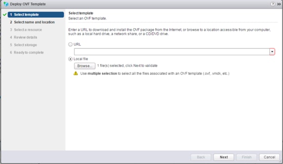
3. Select the OVA file then click Open.
4. Click Next.
5. Specify the name and confirm the location for the CWOM placement and click Next.
6. In select resource page, select the Host/Cluster and click Next.
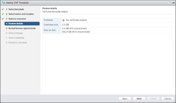
7. Click Next after Review details.
8. Click Accept EULA Agreement and click Next.
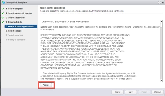
9. Select virtual disk format as “Thin Provisioning” and then select the deployment datastore.
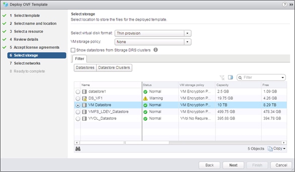
10. Click Next.
11. Select your virtual network and click Next.
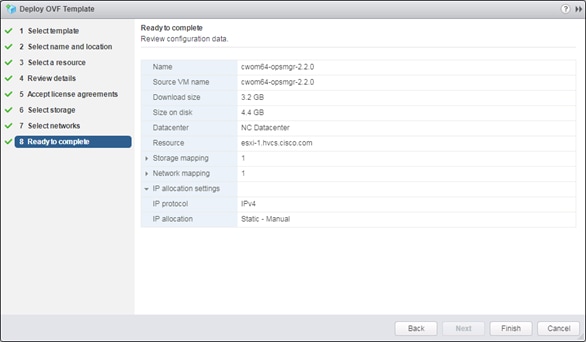
12. Review your configuration and click Finish to deploy CWOM.
Initial Cisco Workload Optimization Manager Setup
Many installations use DHCP for dynamic IP address allocation. You can also specify a static address via the virtual machine’s IP configuration. Workload Optimization Manager includes a script to assist you with this. As root, run ipsetup from the command line.
To specify a static IP address, follow these steps:
1. Turn On and Open a console window to the Workload Optimization Manager VM.
2. Default login as : root
3. Password : vmturbo
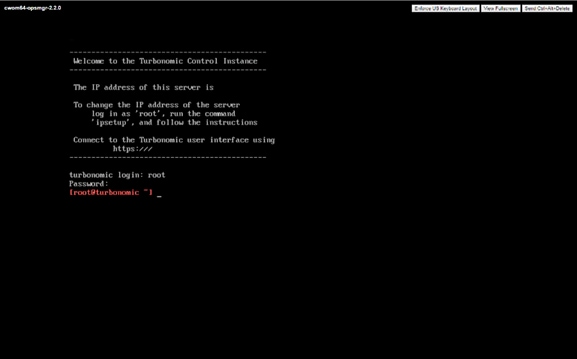
4. Us the command “ipsetup” to assign the ip address. System will open IP assignment wizard
5. Enter the following responses as prompted:
6. Do you want to user DHCP or set a static IP (dhcp/static):: static
7. Enter the IP Address for this machine :: IP Address from OOB Mgmt. Network
8. Enter the network mask for this machine :: subnet mask of OOB Mgmt. Network
9. Enter the Gateway address for this machine :: Gateway of OOB Mgmt. Network
10. Enter DNS Server(s) IP Address for the machine (Separate from each other by a space) :: DNS Server ip address
11. Enter the Domain name for this machine:: domain name of the CWOM
12. Do you sure you want to use these settings? (y/n) :: y
13. Do you want to configure Proxy Server? (y/n) ::n
14. Do you want to restart network the network now? (y/n) y
![]() Provide your Proxy Server setting, if you want to configure your proxy server.
Provide your Proxy Server setting, if you want to configure your proxy server.
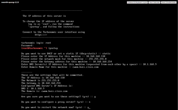
15. To verify the given network information, write “ifconfig eth0” and close the console connection.
NTP Server Configuration
It is important that you synchronize the clock on the Workload Optimization Manager server with the devices on the same network. You will specify the timeserver or servers that Workload Optimization Manager will use to synchronize its clock. You should also set the system clock to your current time zone. Workload Optimization Manager runs regular data maintenance processes. To minimize performance impact, it runs these processes at night. To ensure that these processes run at the proper local time, you should synchronize the VM with your local time zone.
Workload Optimization Manager includes a script to assist you with this. As root, run timesync from the command line:
[root@turbonomic ~] timesync
=====================
Current NTP Servers :
=====================
0.centos.pool.ntp.org
1.centos.pool.ntp.org
2.centos.pool.ntp.org
3.centos.pool.ntp.org
Timezone :
==========
America/New_York(EDT,-0400)
Do you want to delete the current NTP servers (y/n) :: y
Enter NTP Server(s) IP/DNS for this machine (separated from each other by a space) :: 172.26.163.254
Do you want to change the Timezone (y/n) :: n
=================
New NTP Servers :
=================
172.26.163.254
TimeZone :
Are these settings correct (y/n) :: y
/sbin/restorecon reset /etc/chrony.conf context unconfined_u:object_r:user_tmp_t:s0->unconfined_u:object_r:etc_t:s0
Open Ports
To use Cisco Workload Optimization Manager in your environment, open the following ports:
| Port |
To Support |
| 80 |
Incoming browser connections over HTTP |
| 443 |
Incoming browser connections over HTTPS Proactive Support (automatically generate support tickets for Cisco Workload Optimization Manager issues) |
For browser connection with the server, you should use either port 80 or 443
![]() Various targets that you use with Cisco Workload Optimization Manager may require you to open ports on those targets servers to allow communications with CWOM.
Various targets that you use with Cisco Workload Optimization Manager may require you to open ports on those targets servers to allow communications with CWOM.
License Installation and First Time Login
To use Cisco Workload Optimization Manager, open a Web browser to the IP Address of the installed VM, and follow these steps:
1. Connect to your Workload Optimization Manager server via a Web browser.
2. As you perform the initial login, you will be prompted to set the password for the administrator account. To continue, provide the new password for this account.
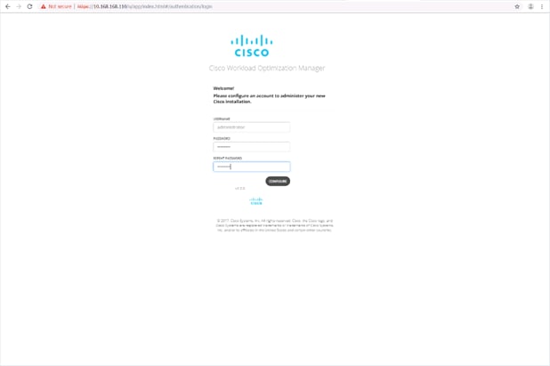
3. The Wizard will be open for the License Installation, Target Configuration, and Email setup.
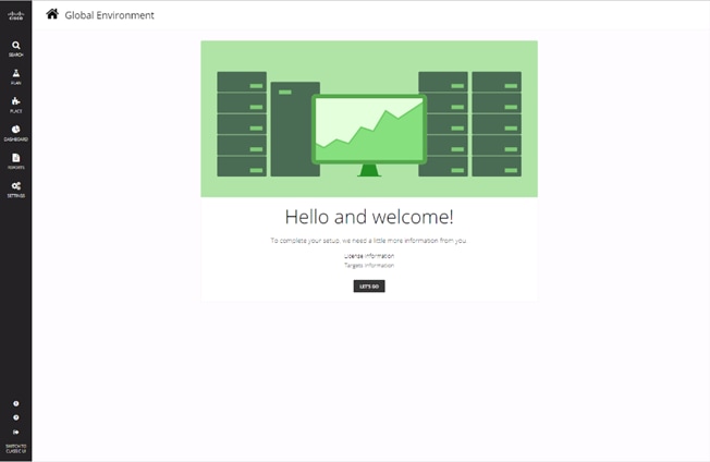
4. Click LET’s GO to begin.
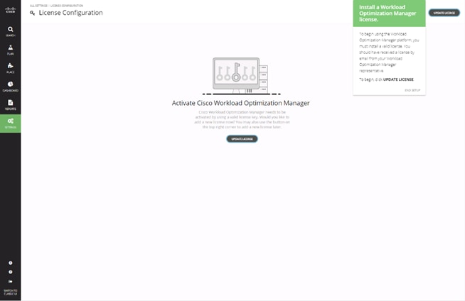
5. Click UPDATE LICENSE to activate your license.
6. Drag the license file or select click to browse to find your license file.
7. Click Save.
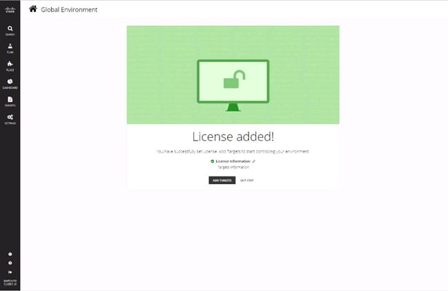
8. Click ADD TARGETS for Target Configuration.
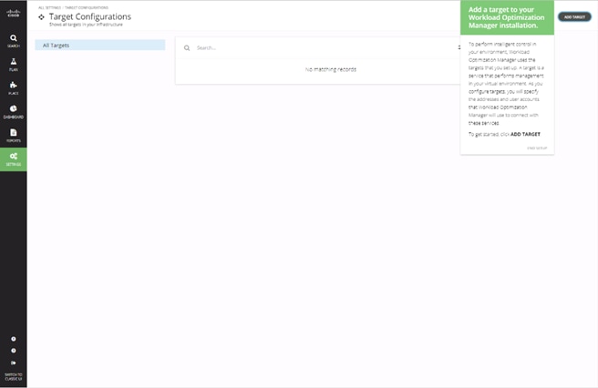
9. Click ADD TARGET within the Targets Configuration page.
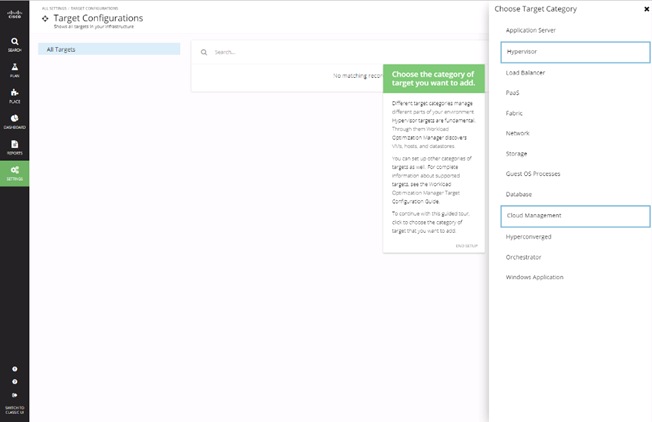
10. Select Hypervisor to add the vCenter for the environment.
11. Select the vCenter icon from the hypervisor listing.
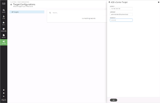
12. Enter the vCenter Address and Username/Password, then click ADD.
13. Click DONE.
14. Select ADD TARGET again.
15. Click Fabric within the Choose Target Category options to add UCSM.
16. Click the Cisco UCS Manager icon.
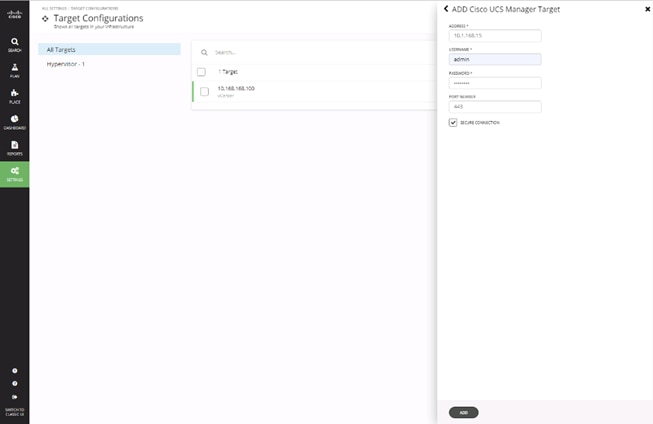
17. Enter the UCSM Address and Username/Password, then click ADD.
Update CWOM
At the time of this CVD, there is a 2.2.3 update to the 2.2.0 OVA for CWOM that has been installed. To install this update, follow these steps:
1. Download the update64_package-v2.2.3.zip file for the 2.2.3 release from software.cisco.com under Workload Optimization Manager 2.0.
2. From a root shell on the CWOM appliance, run the command:
[root@turbonomic ~] setenforce 0
3. From a web browser, connect to the CWOM appliance at: https://<CWOM Address>/update.html
4. Enter administrator for the Username and provide the configured Password.
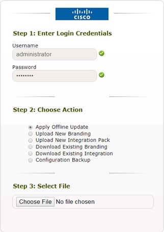
5. Select the Apply Offline Update option and select Choose File.
6. Select the update64_package-v2.2.3.zip and click Open.
7. Click Upload.
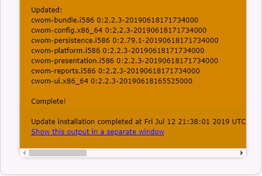
8. Close the browser window after the update completes.
Documentation Quick Links
· Target Configuration: http://docs.turbonomic.com/target-configuration
· Fabric Manager Targets: http://docs.turbonomic.com/fabric-manager-targets
· Complete CWOM Documentation: http://docs.turbonomic.com/
· Green Circle Community Forum: https://greencircle.vmturbo.com/welcome
· CWOM Resource Library: https://turbonomic.com/resources/
Ramesh Isaac, Technical Marketing Engineer, Cisco Systems, Inc.
Ramesh Isaac is a Technical Marketing Engineer in the Cisco UCS Data Center Solutions Group. Ramesh has worked in the data center and mixed-use lab settings since 1995. He started in information technology supporting UNIX environments and focused on designing and implementing multi-tenant virtualization solutions in Cisco labs before entering Technical Marketing where he has supported converged infrastructure and virtual services as part of solution offerings as Cisco. Ramesh has certifications from Cisco, VMware, and Red Hat.
Arvin Jami, Virtualization Solution Architect, Hitachi Vantara
Arvin Jami began his career at Hitachi Data Systems as an intern in 2014. Since then he has held the position of Technical Marketing Engineer where he demonstrated and positioned Hitachi products to fortune 500 companies. He is now the Virtualization Solution Architect in the Hitachi Vantara Converged Product Engineering Group. Arvin has a Bachelor of Science degree in Electrical Engineering from San Jose State University.
Acknowledgements
For their support and contribution to the design, validation, and creation of this Cisco Validated Design, the authors would like to thank:
· Haseeb Niazi, Technical Marketing Engineer, Cisco Systems, Inc.
· Sreeni Edula, Technical Marketing Engineer, Cisco Systems, Inc.
· Archana Sharma, Technical Marketing Engineer, Cisco Systems, Inc.
· Tim Darnell, Master Solutions Architect and Product Owner, Hitachi Vantara
 Feedback