Cisco Application Centric Infrastructure Multi-Pod Configuration White Paper
Available Languages
Bias-Free Language
The documentation set for this product strives to use bias-free language. For the purposes of this documentation set, bias-free is defined as language that does not imply discrimination based on age, disability, gender, racial identity, ethnic identity, sexual orientation, socioeconomic status, and intersectionality. Exceptions may be present in the documentation due to language that is hardcoded in the user interfaces of the product software, language used based on RFP documentation, or language that is used by a referenced third-party product. Learn more about how Cisco is using Inclusive Language.
The Cisco® Application Centric Infrastructure (Cisco ACI™) Multi-Pod solution is an evolution of the stretched-fabric use case. Multiple pods provide intensive fault isolation in the control plane along with infrastructure cabling flexibility. As the name indicates, it connects multiple Cisco Application Policy Infrastructure Controller (APIC) pods using a Layer 3 interpod network (IPN).
Note: Pod spine switches cannot be connected back to back. IPN supports only Open Shortest Path First (OSPF) connectivity between the IPN and the spine switches. Though each pod consists of its own spine and leaf switches, all the pods reside within the same fabric and are managed by a single APIC cluster. This approach provides a single management and policy domain across all pods for end-to-end policy enforcement. In the data plane, the Multi-Pod solution uses Multiprotocol Border Gateway Protocol (MP-BGP) Ethernet Virtual Private Network (EVPN) connectivity over the IPN between the spine switches from each pod for communication using Virtual Extensible LAN (VXLAN) encapsulation.
This document describes a Multi-Pod deployment with five APICs. You can refer to the Cisco ACI Multi-Pod white paper for additional details.
Deploying a Multi-Pod solution with multiple Cisco APICs
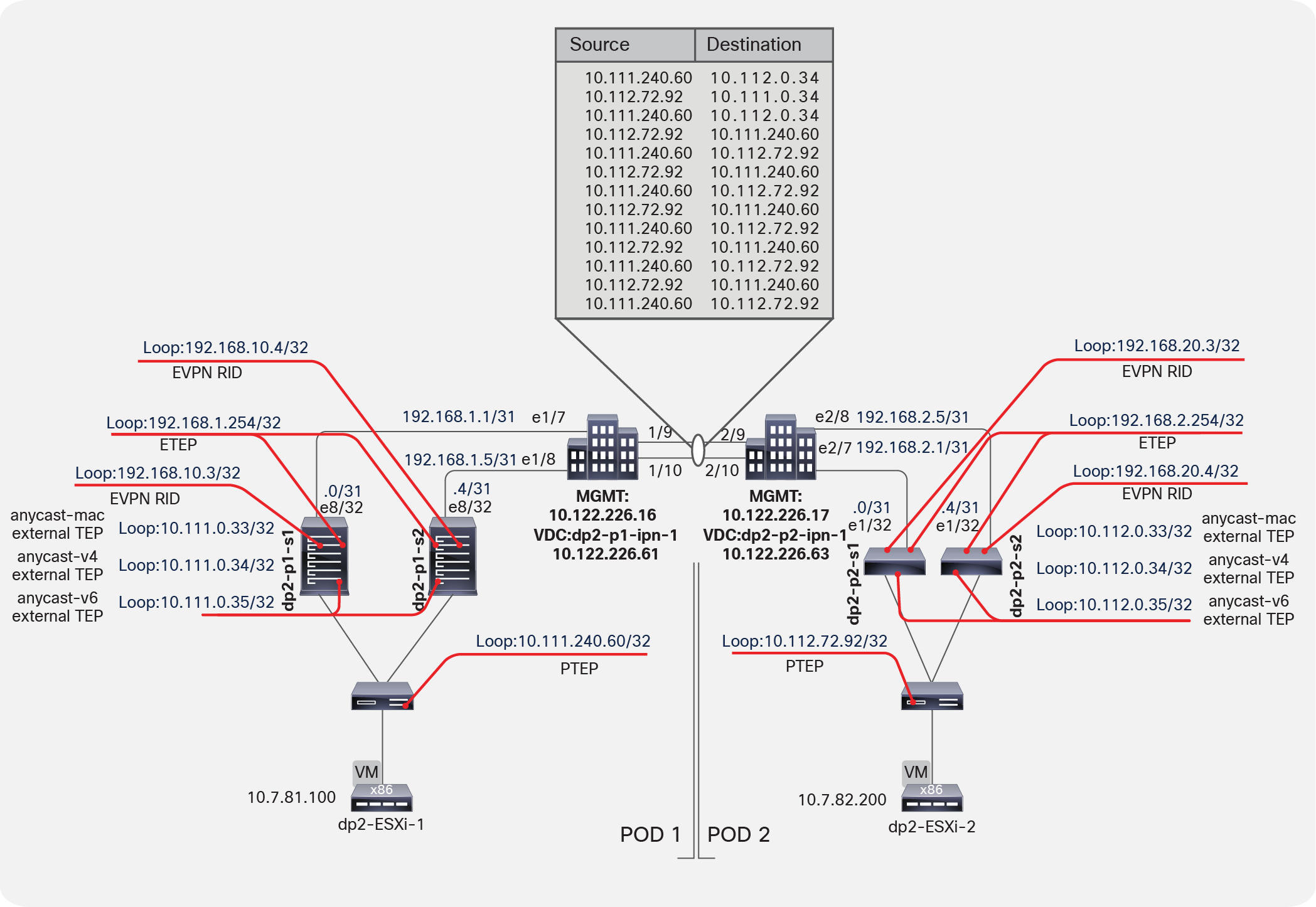
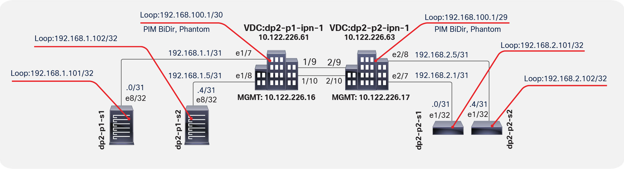
The topology in Figure 1 shows a Multi-Pod design with five APICs. The Multi-Pod setup uses two Cisco Nexus® 7000 Series Switches configured using Virtual Device Contexts (VDCs) for the IPN setup.
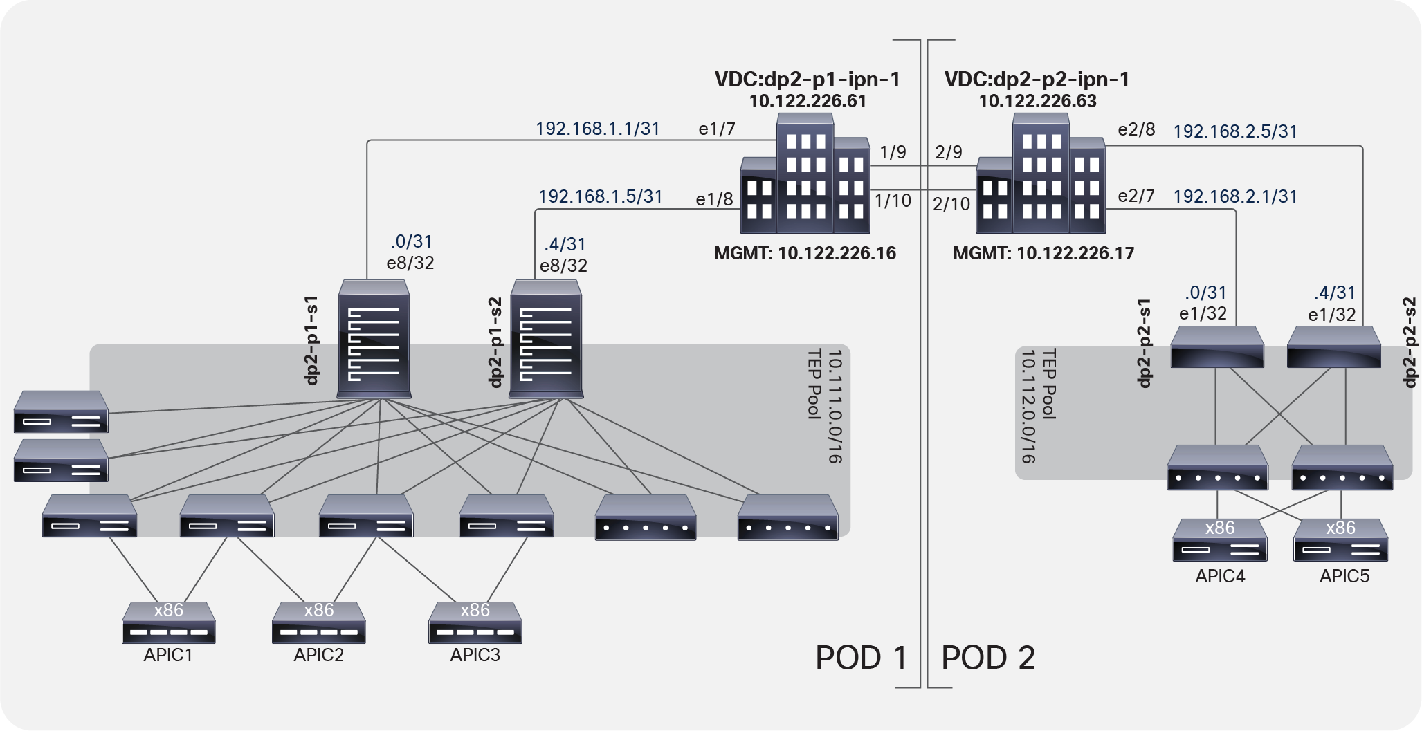
Multi-Pod design topology
Follow these steps to configure a Multi-Pod solution with multiple APICs:
2. Configure a Virtual Routing and Forwarding (VRF) instance.
3. Configure the OSPF process.
5. Configure Domain Host Configuration Protocol (DHCP) relay.
6. Configure IPN interfaces with DHCP relay.
Note: The following instructions are for the Cisco Nexus 7000 Series. For different platforms, such as the Cisco Aggregation Services Router (ASR) running Cisco IOS® Software or the Cisco ASR 9000 Series with Cisco IOS XR Software, the configuration varies but can easily be derived.
With Link Layer Discovery Protocol (LLDP) you can verify the connections between the spine switch and the IPN ports. Make sure that you enable LLDP on the Cisco Nexus switch.
dp2-p1-ipn1(conf)# feature lldp
dp2-p1-ipn1(conf)# exit
!
dp2-p1-ipn1# show lldp neighbors
Capability codes:
(R) Router, (B) Bridge, (T) Telephone, (C) DOCSIS Cable Device
(W) WLAN Access Point, (P) Repeater, (S) Station, (O) Other
Device ID Local Intf Hold-time Capability Port ID
dp2-p1-s1 Eth1/7 120 BR Eth8/32
dp2-p1-s2 Eth1/8 120 BR Eth8/32
dp2-p2-ipn1 Eth1/9 120 BR Eth2/9
dp2-p2-ipn1 Eth1/10 120 BR Eth2/10
Total entries displayed: 4
dp2-p1-ipn1#
dp2-p2-ipn1(conf)# feature lldp
dp2-p2-ipn1(conf)# exit
!
dp2-p2-ipn1# show lldp neighbors
Capability codes:
(R) Router, (B) Bridge, (T) Telephone, (C) DOCSIS Cable Device
(W) WLAN Access Point, (P) Repeater, (S) Station, (O) Other
Device ID Local Intf Hold-time Capability Port ID
dp2-p2-s1 Eth2/7 120 BR Eth1/32
dp2-p2-s2 Eth2/8 120 BR Eth1/32
dp2-p1-ipn1 Eth2/9 120 BR Eth1/9
dp2-p1-ipn1 Eth2/10 120 BR Eth1/10
Total entries displayed: 4
dp2-p2-ipn1#
As a best practice, isolate the traffic between the two fabrics across the IPN in a VRF instance because the solution exposes the underlay (overlay-1) of Cisco ACI to the IPN.
| dp2-p1-ipn-1 |
dp2-p2-ipn-1 |
| vrf context IPN-1 |
vrf context IPN-1 |
Note: The use of a dedicated VRF is simply a best-practice recommendation to simplify operations in the IPN when that infrastructure is used at the same time for other connectivity requirements. It is, however, possible and fully supported to use the global table routing domain for inter-site communication, if desired.
On each IPN switch, enable and configure OSPF (Figure 2). As a best practice for isolating the network used between pods, create the VRF instance in the OSPF process as well. Currently, OSPF is the only supported routing protocol for peering an IPN switch and a Cisco ACI spine switch.
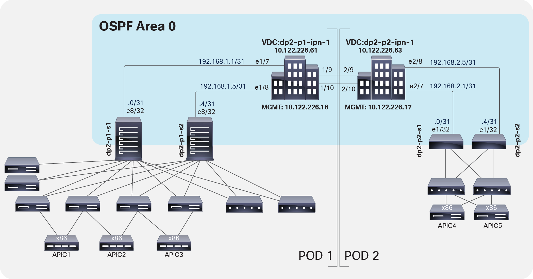
OSPF configuration
| dp2-p1-ipn-1 |
dp2-p2-ipn-1 |
| feature ospf ! router ospf IPN vrf IPN-1 router-id 1.1.1.1 log-adjacency-changes |
feature ospf ! router ospf IPN vrf IPN-1 router-id 2.2.2.1 log-adjacency-changes |
Follow these guidelines for configuring multicast on the IPN switch:
● Bidirectional Protocol-Independent Multicast (Bidir PIM) for Broadcast, unknown Unicast, and Multicast (BUM) traffic between pods must be supported.
◦ IPN device must support Bidir PIM for a range of at least /15.
◦ Because of this requirement all first generation N9Ks are not supported IPN devices because the Broadcom T2/T2+ ASICs only support a maximum Bidir PIM range of /24. The N9Ks will let you configure larger ranges for Bidir PIM but it will not work as expected.
● The multicast Rendezvous Point (RP) must be defined.
● A loopback interface part of a subnet that includes the RP address must be defined on at least a pair of IPN devices (for the sake of redundancy).
Bidir PIM does not support the concept of an anycast rendezvous point like traditional PIM Sparse Mode (PIM-SM) Any-Source Multicast (ASM). Bidir PIM redundancy is based on a backup model, or phantom rendezvous points. In other words, a single rendezvous point handles everything, and in the case of a failure, another rendezvous point takes over. This model is achieved by configuring different subnet masks on these loopback addresses for each IPN switch, which allows the use of the longest-prefix-match logic in the routing process.
Bidir PIM is used for many-to-many communication and uses only the shared tree for traffic distribution. Shared trees handle the distribution of multicast data traffic from the rendezvous point to the receivers and use a mechanism for the sources called the Designated Forwarder (DF). The designated forwarder decides which packets need to be forwarded upstream to the rendezvous point. The designated forwarder is elected by all the PIM neighbors in a subnet advertising their unicast routes to the rendezvous point, with the router with the best route being elected. With bidir PIM, the same shared tree is used for traffic to be sent from the rendezvous point to receivers and from the sources to the rendezvous point. Thus, sources can also be receivers, and vice-versa, leading to bidirectional branches within the shared tree.
Note: The spine nodes generating and receiving BUM traffic act like multicast sources and receivers.
Figure 3 shows the multicast configuration.
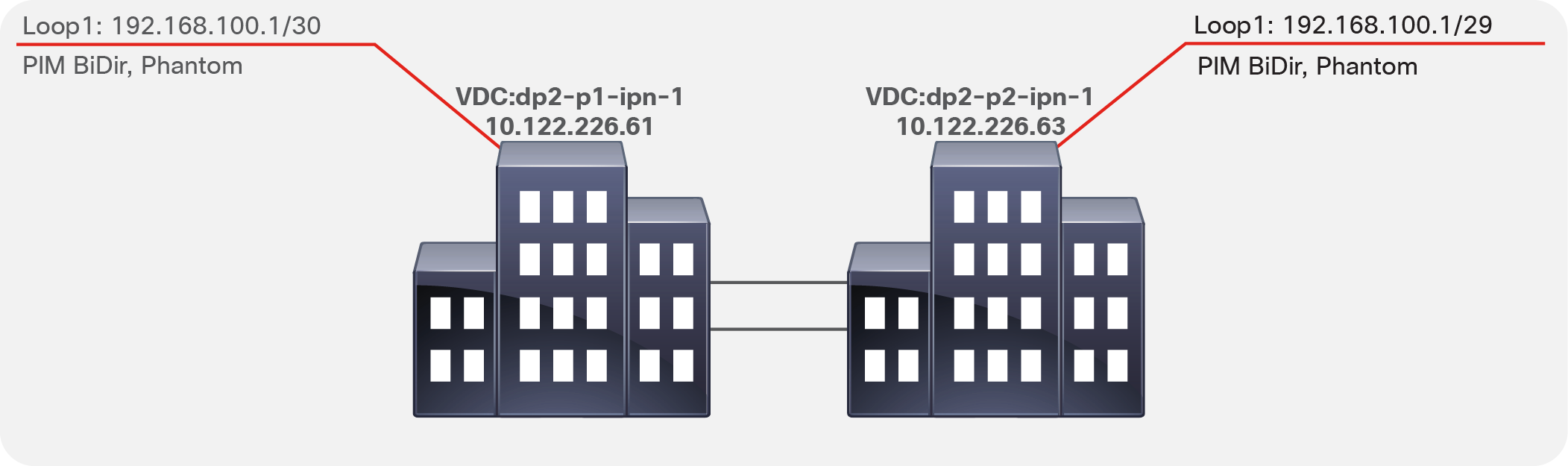
Multicast configuration
| dp2-p1-ipn-1 |
dp2-p2-ipn-1 |
| interface loopback1 description BIDIR Phantom RP vrf member IPN-1 ip address 192.168.100.1/30 ip ospf network point-to-point ip router ospf IPN area 0.0.0.0 ip pim sparse-mode |
interface loopback1 description BIDIR Phantom RP vrf member IPN-1 ip address 192.168.100.1/29 ip ospf network point-to-point ip router ospf IPN area 0.0.0.0 ip pim sparse-mode |
When isolating the IPN in a VRF instance, configure the static designated rendezvous point address (part of the IP subnet previously defined under the loopback interface) under the VRF instance and use the bidir configuration keyword at the end of the configuration syntax.
| dp2-p1-ipn-1 |
dp2-p2-ipn-1 |
| vrf context IPN-1 ip pim rp-address 192.168.100.2 group-list 225.0.0.0/15 bidir ip pim rp-address 192.168.100.2 group-list 239.255.255.240/28 bidir |
vrf context IPN-1 ip pim rp-address 192.168.100.2 group-list 225.0.0.0/15 bidir ip pim rp-address 192.168.100.2 group-list 239.255.255.240/28 bidir |
In the configuration samples above, 192.168.100.2 is the RP address. All the devices in the IPN will see the RP as reachable via the dp2-p1-ipn1 device, since it advertises a 192.168.100.0/30 subnet that includes the specific RP address. If that device were to fail, all the IPN routers would immediately switch to dp2-p2-ipn-1, which advertises the 192.168.100.0/29 subnet.
Configure the IPN Interfaces.
| dp2-p2-ipn-1 |
|
| interface Ethernet1/7 mtu 9150 no shutdown
interface Ethernet1/7.4 description dp2-p1-s1 mtu 9150 encapsulation dot1q 4 vrf member IPN-1 ip address 192.168.1.1/31 ip ospf network point-to-point ip router ospf IPN area 0.0.0.0 ip pim sparse-mode no shutdown
interface Ethernet1/8 mtu 9150 no shutdown
interface Ethernet1/8.4 description dp2-p1-s2 mtu 9150 encapsulation dot1q 4 vrf member IPN-1 ip address 192.168.1.5/31 ip ospf network point-to-point ip router ospf IPN area 0.0.0.0 ip pim sparse-mode no shutdown
interface Ethernet1/9.4 description dp2-p2-ipn1 link 1 mtu 9150 encapsulation dot1q 4 vrf member IPN-1 ip address 192.168.3.0/31 ip ospf network point-to-point ip router ospf IPN area 0.0.0.0 ip pim sparse-mode no shutdown
interface Ethernet1/10.4 description dp2-p2-ipn1 link 2 mtu 9150 encapsulation dot1q 4 vrf member IPN-1 ip address 192.168.3.2/31 ip ospf network point-to-point ip router ospf IPN area 0.0.0.0 ip pim sparse-mode no shutdown |
interface Ethernet2/7 mtu 9150 no shutdown
interface Ethernet2/7.4 description dp2-p2-s3 mtu 9150 encapsulation dot1q 4 vrf member IPN-1 ip address 192.168.2.1/31 ip ospf network point-to-point ip router ospf IPN area 0.0.0.0 ip pim sparse-mode no shutdown
interface Ethernet2/8 mtu 9150 no shutdown
interface Ethernet2/8.4 description dp2-p2-s4 mtu 9150 encapsulation dot1q 4 vrf member IPN-1 ip address 192.168.2.5/31 ip ospf network point-to-point ip router ospf IPN area 0.0.0.0 ip pim sparse-mode no shutdown
interface Ethernet2/9.4 description dp2-p1-ipn1 link 1 mtu 9150 encapsulation dot1q 4 vrf member IPN-1 ip address 192.168.3.1/31 ip ospf network point-to-point ip router ospf IPN area 0.0.0.0 ip pim sparse-mode no shutdown
interface Ethernet2/10.4 description dp2-p1-ipn1 link 2 mtu 9150 encapsulation dot1q 4 vrf member IPN-1 ip address 192.168.3.3/31 ip ospf network point-to-point ip router ospf IPN area 0.0.0.0 ip pim sparse-mode no shutdown |
The use of subinterfaces on the links connecting the IPN devices to the spines is mandatory; it is, however, optional for the links between IPN devices and is only required when multiple VRFs need to be connected over the same physical interface.
Each IPN switch connecting to a Cisco ACI spine switch needs to have the DHCP feature enabled. This feature will be used to enable DHCP relay on the IPN switch subinterfaces connected to remote pod spine switches.
| dp2-p1-ipn-1 |
dp2-p2-ipn-1 |
| feature dhcp service dhcp ip dhcp relay |
feature dhcp service dhcp ip dhcp relay |
Configuring IPN interfaces for DHCP relay
The configuration of the interfaces must include a relay to the destination IP addresses of the APICs located in the fabrics. Any DHCP request received is then forwarded. This configuration enables automatic discovery of the fabric nodes across the IPN.
| dp2-p1-ipn-1 |
dp2-p2-ipn-1 |
| interface Ethernet 1/7.4 ip dhcp relay address 10.111.0.1 ip dhcp relay address 10.111.0.2 ip dhcp relay address 10.111.0.3 ip dhcp relay address 10.111.0.4 ip dhcp relay address 10.111.0.5
interface Ethernet 1/8.4 ip dhcp relay address 10.111.0.1 ip dhcp relay address 10.111.0.2 ip dhcp relay address 10.111.0.3 ip dhcp relay address 10.111.0.4 ip dhcp relay address 10.111.0.5 |
interface Ethernet 2/7.4 ip dhcp relay address 10.111.0.1 ip dhcp relay address 10.111.0.2 ip dhcp relay address 10.111.0.3 ip dhcp relay address 10.111.0.4 ip dhcp relay address 10.111.0.5
interface Ethernet 2/8.4 ip dhcp relay address 10.111.0.1 ip dhcp relay address 10.111.0.2 ip dhcp relay address 10.111.0.3 ip dhcp relay address 10.111.0.4 ip dhcp relay address 10.111.0.5 |
Configuring Cisco APIC for a Multi-Pod setup
In a Multi-Pod setup, the configuration of the APIC clusters should be specific to the pod to which they belong. Because the Tunnel Endpoint (TEP) pool for each pod must be unique, each pod has its own TEP address pool. This setup enables east-west communication for endpoints connected to separate pods via VXLAN tunnels established between the specific leaf nodes VTEP addresses taken from those not overlapping TEP address pools.
In Figure 4, the IPN routers (in this case, the Cisco Nexus 7000 Series Switches) learn routes that are redistributed from the underlay Intermediate System–to–Intermediate System (IS-IS) network of the Cisco ACI fabric (overlay-1) to the IPN OSPF process. This redistribution can occur in the reverse direction as well, with the IPN OSPF process redistributed to the Cisco ACI fabric underlay IS-IS network. This processing occurs on the spine switches. This route redistribution is also how TEPs between the pods are learned. As best practice configuration, you should use a VRF instance in the IPN routers to isolate the fabric-to-fabric network from the outside world. In a Multi-Pod setup, you do not need to expose the inside of the Cisco ACI fabric to the entire network.
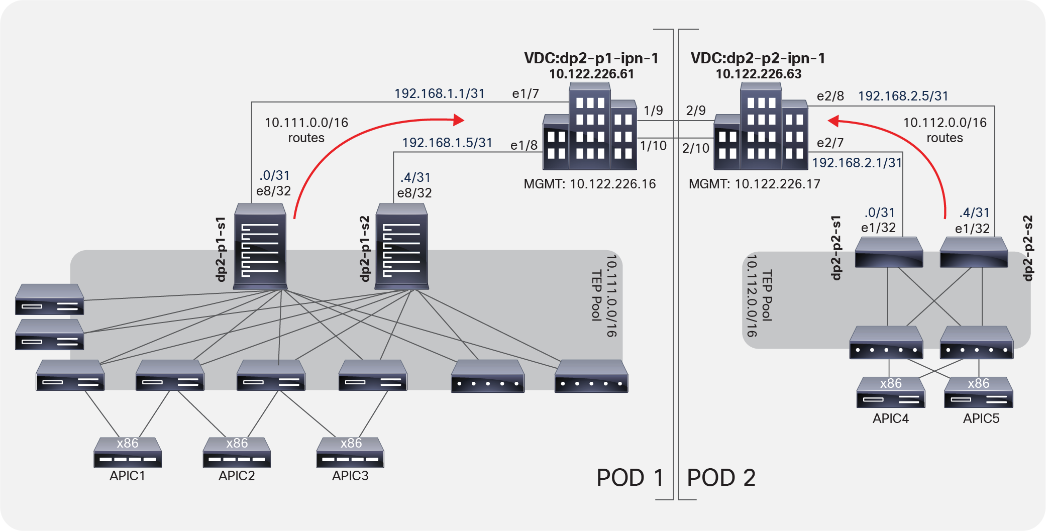
IPN routers learn routes through route redistribution
You need different TEP pools so that the subnet route redistribution works correctly and each side learns the proper routes to the remote TEPs across the IPN.
You must configure the APICs for this new feature. In particular, the APICs must exist in different pods with different pod identifiers. Cisco ACI provides a pod identifier, always defined as 1. There are two scenarios:
● New (greenfield) installation: Each new APIC should exist in a pod. If you have a three-APIC cluster and you want to move one APIC to a new data center, then the best approach is to decommission this APIC, wipe the configuration, and move the APIC to the new data center (pod) to be reconfigured in that different pod.
● Existing (brownfield) installation: This scenario includes newly added and configured APIC fabrics in a new data center and pod location, with the new pod ID and appropriate configuration.
Table 1 lists the APIC fabric initialization configuration parameters. The pod ID and the TEP address pool are the critical elements.
Table 1. Cisco APIC fabric initialization configuration parameters
| Configuration |
APIC1 |
APIC2 |
APIC3 |
APIC4 |
APIC5 |
| Fabric name |
dp2-fabric |
dp2-fabric |
dp2-fabric |
dp2-fabric |
dp2-fabric |
| Fabric ID |
1 |
1 |
1 |
1 |
1 |
| Number of controllers |
5 |
5 |
5 |
5 |
5 |
| Pod ID |
1 |
1 |
1 |
2 |
2 |
| Controller ID |
1 |
2 |
3 |
4 |
5 |
| Controller name |
dp2-apic1 |
dp2-apic2 |
dp2-apic3 |
dp2-apic4 |
dp2-apic5 |
| TEP address pool |
10.111.0.0/16 |
10.111.0.0/16 |
10.111.0.0/16 |
10.111.0.0/16 |
10.111.0.0/16 |
| VLAN ID for infrastructure VLAN |
3967 |
3967 |
3967 |
3967 |
3967 |
| Administrator credentials |
admin/password |
||||
| IPv6 enabled out of band |
N |
N |
N |
N |
N |
| Management IP |
<IP>/<mask> |
<IP>/<mask> |
<IP>/<mask> |
<IP>/<mask> |
<IP>/<mask> |
| Default gateway |
<IP> |
<IP> |
<IP> |
<IP> |
<IP> |
You do not need to have an APIC node in your remote Multi-Pod environment. The discovery of the fabric will occur across the IPN without the APIC nodes in the remote site.
Note: The same TEP address pool (10.111.0.0/16 in the specific example in Table 1) must be used as the initialization configuration parameter for all of the APIC nodes that are connected to the Multi-Pod fabric, independently from the specific pod to which the nodes are connected. This is because all of the APIC nodes get assigned an IP address from the TEP pool that is associated to the first pod that was brought up as part of the Multi-Pod fabric (also known as the “seed” pod).
Note: The deployment of a 5-node APIC cluster across two pods is not recommended and is only required when the total number of leaf nodes connected to the Multi-Pod fabric is more than 200. With fewer than a total of 80 leaf nodes, it is strongly recommended to deploy a 3-active-node APIC cluster, whereas between 80 and 200 leaf nodes it is possible to deploy a 4-active-node APIC cluster, leveraging two nodes per pod. For more information on this, please refer to the ACI Multi-Pod white paper below:
To set up the APIC, follow these steps:
1. Configure access policies. Configure access policies for all the interfaces on the spine switches used to connect to the IPN. Define these policies as spine access policies. Use these policies to associate an Attached Entity Profile (AEP) for a Layer 3 domain that uses VLAN 4 for the encapsulation for the subinterface. VLAN 4 must be used; you cannot modify or change this requirement. Define these subinterfaces in the same way as normal leaf access ports. The subinterfaces are used by the infrastructure Layer 3 Outside (L3Out) interface that you define.
2. Define the Multi-Pod environment. In a Multi-Pod setup, you define the Fabric TEP (FTEP) address for the spines facing each other across the IPN. You also define the Layer 3 interfaces between the IPN and the spine interfaces.
3. Configure the IPN. The IPN creates OSPF adjacencies with the spine switches and exchanges the routes of the underlying IS-IS network part of VRF overlay-1. The configuration of the IPN defines the DHCP relay, which is critical for learning adjacencies because the DHCP frames forwarded across the IPN will reach the primary APIC in Pod1 to get a DHCP address assignment from the TEP pool. Without DHCP relay in the IPN, zero-touch provisioning will not occur for Cisco ACI nodes deployed in Pod2.
4. Establish the interface access policies for the second pod. If you do not establish the access policies for the second pod, then the second pod cannot complete the process of joining the fabric. You can add the device to the fabric, but it does not complete the discovery process. In Cisco ACI, OSPF adjacency cannot be established because VLAN 4, the OSPF interface profile, and the external Layer 3 definition don't exist, and the spine switch has no way to talk to the original pod. You can reuse the access policies of Pod1 as long as the spine interfaces you are using on Pod1 and Pod2 are the same. In many cases, the spine interfaces connecting the two pods will not be the same because Pod2 may have a smaller spine. If the spine interfaces in both pods are the same and the ports in all the switches also are the same, then the only action you need to take is to add the spine switches to the switch profile that you define.
Note the following when configuring the APIC:
● A spine switch must have an active leaf-facing link (LLDP up). Otherwise, it is deemed unused and cannot be used by the fabric.
● LLDP must be enabled on the IPN switch.
● At least one spine switch should be configured with a BGP EVPN session for peering with remote pods.
● The Round-Trip Time (RTT) is up to 50 milliseconds (ms) for Cisco ACI Release 2.3 and later.
Using the Cisco APIC fabric setup script
The fabric setup script requests a fabric ID, with 1 being the default suggested value. You then need to configure the pod ID according to the location of the APIC. For example, as shown in Table 1, APICs 4 and 5 will be in Pod2. Thus, in their respective fabric setup scripts, the pod ID value will be 2.
Cluster configuration ...
Enter the fabric name [ACI Fabric1 #1]: dp2-fabric
Enter the fabric ID (1-128) [1]:
Enter the number of controllers in the fabric (1-9) [3]: 5
Enter the POD ID (1-9): [1]
Enter the controller ID (1-3) [1]:
Enter the controller name [apic1]: dp2-apic1
Enter address pool for TEP addresses [10.0.0.0/16]: 10.111.0.0/16
Note: The infra VLAN ID should not be used elsewhere in your environment
and should not overlap with any other reserved VLANs on other platforms.
Enter the VLAN ID for infra network (2-4094): 3967
Enter address pool for BD multicast addresses (GIPO) [225.0.0.0/15]:
Out-of-band management configuration ...
Enter the IP address for out-of-band management: 10.122.226.31/24
Enter the IP address of the default gateway [None]: 10.122.226.1
Enter the interface speed/duplex mode [auto]:
Administrator user configuration...
Enable strong passwords? [Y]
Enter the password for admin:
Configuring the Multi-Pod setup
When running ACI release 4.2(1) or newer, it is strongly recommended to use the APIC wizard to configure the Multi-Pod setup. The wizard takes care of configuring:
● An L3Out in the infra tenant specifying the spine nodes and interfaces to connect each pod to the IPN.
● Access policies for the spine interfaces connecting to the IPN.
● An internal TEP pool to be assigned to each pod.
● An external TEP pool to be assigned to each pod, used to define the control-plane IP addresses on the spines used for establishing MP-BGP EVPN adjacencies across pods and also to assign an anycast TEP address to each pod used for data-plane traffic.
The step-by-step procedure to run through the APIC wizard is shown in the rest of this section. For more information on how to set up Multi-Pod without using the APIC wizard (using manual configuration instead), please refer to Appendix.
The initial assumptions are the following:
● The first pod in the ACI fabric has been already successfully brought up, and the spines are physically connected to the IPN devices (as shown in Figure 4).
● The IPN devices are properly configured with DHCP-Relay, OSPF, and PIM enabled, as described in the “Configuring the IPN” section.
● The spine and leaf nodes in Pod2 have been powered up and properly cabled to connect with each other and with the IPN devices.
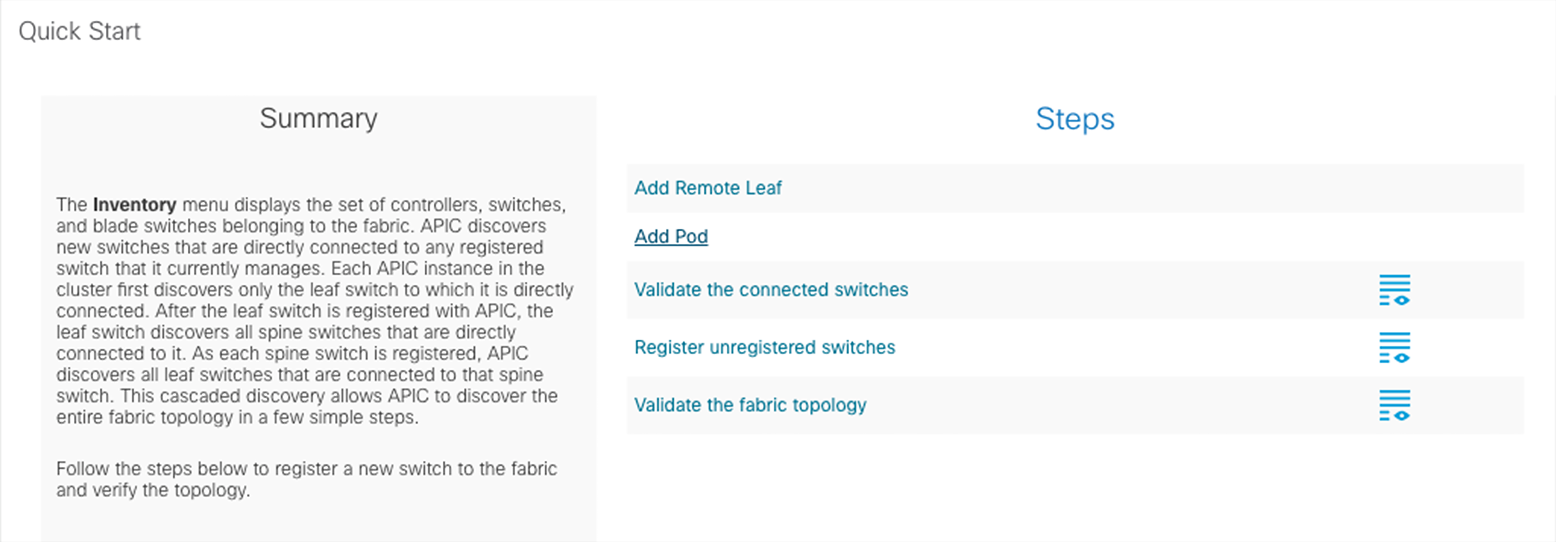
The first configuration-step required configures the connection between the spines in Pod1 and the IPN devices. This action is triggered by selecting “Add Pod” in Fabric à Inventory:
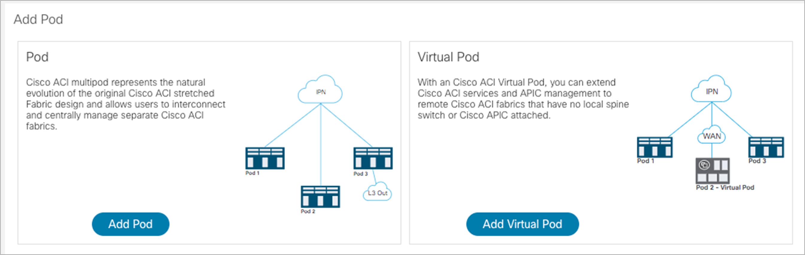
Then select “Add Pod” in the following window, which opens up:
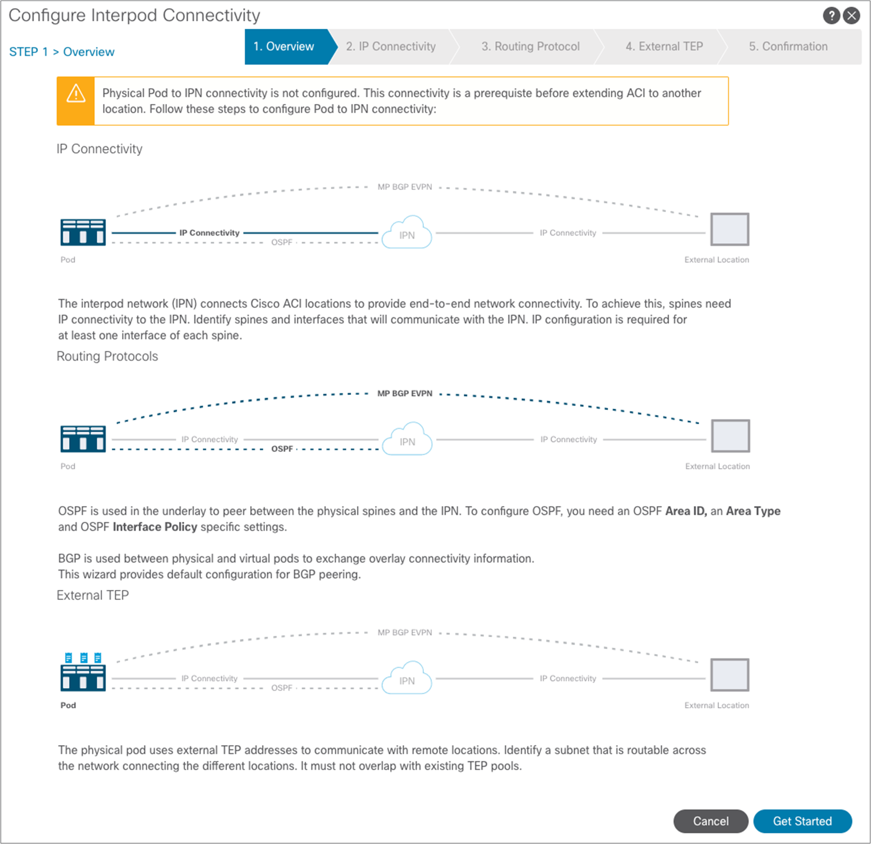
The window to start configuring interpod connectivity is displayed. Select “Get Started.”
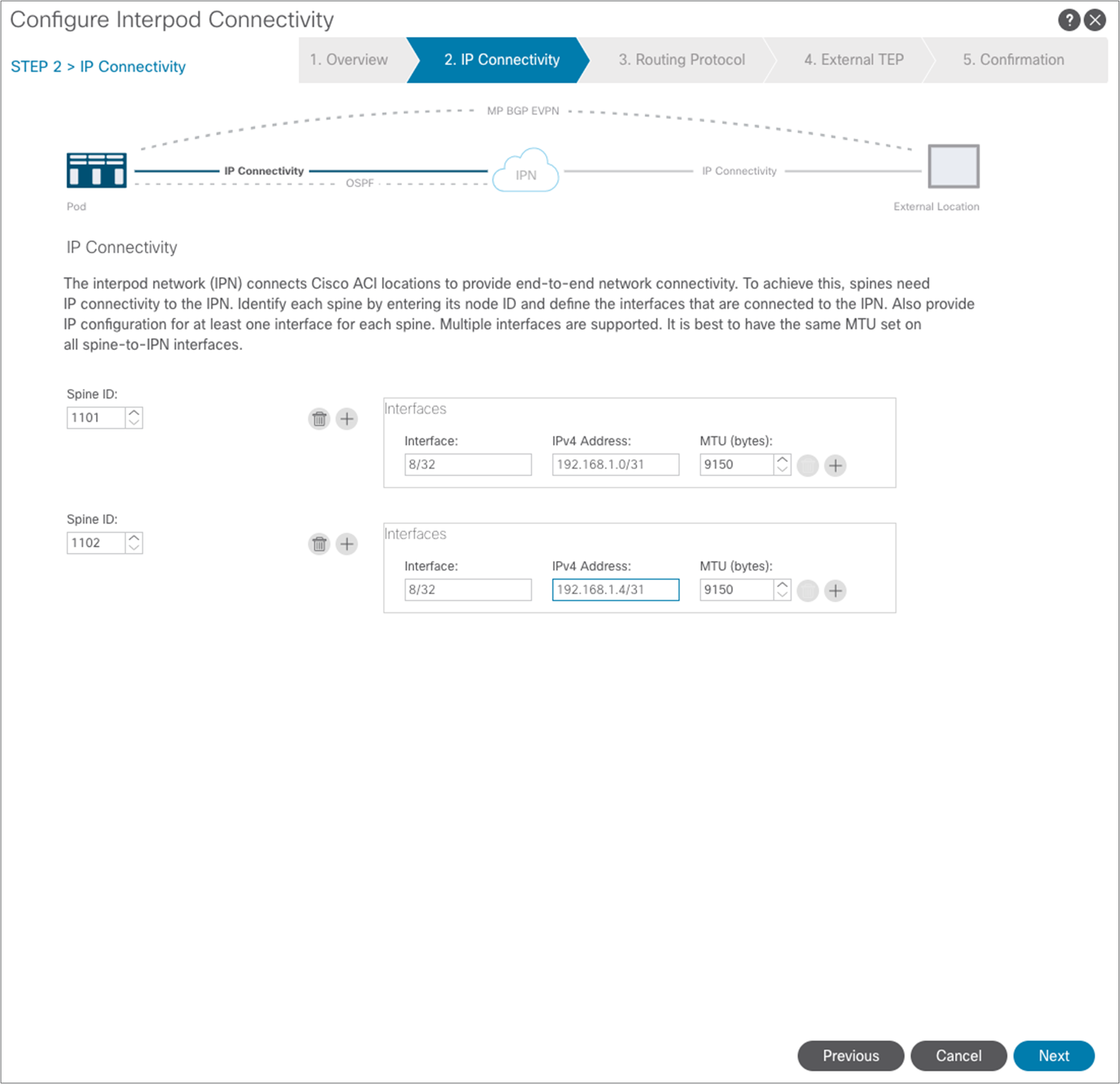
In the next step, you need to select the specific interfaces of the spine nodes connected to the IPN nodes, and assign them their IP addresses. To add more spine nodes (two in our examples), you can hit the “+” button. When you are finished, hit “Next.”
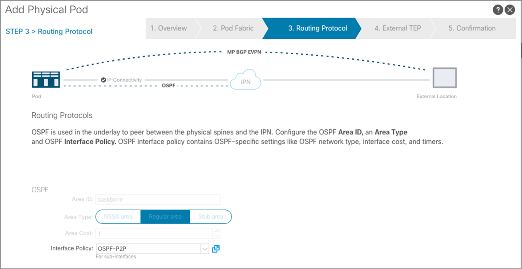
A window opens up to allow enabling of the OSPF routing protocol on the spines’ interfaces. As shown in Figure 2, we are here using OSPF area 0, extending between pods across the IPN.
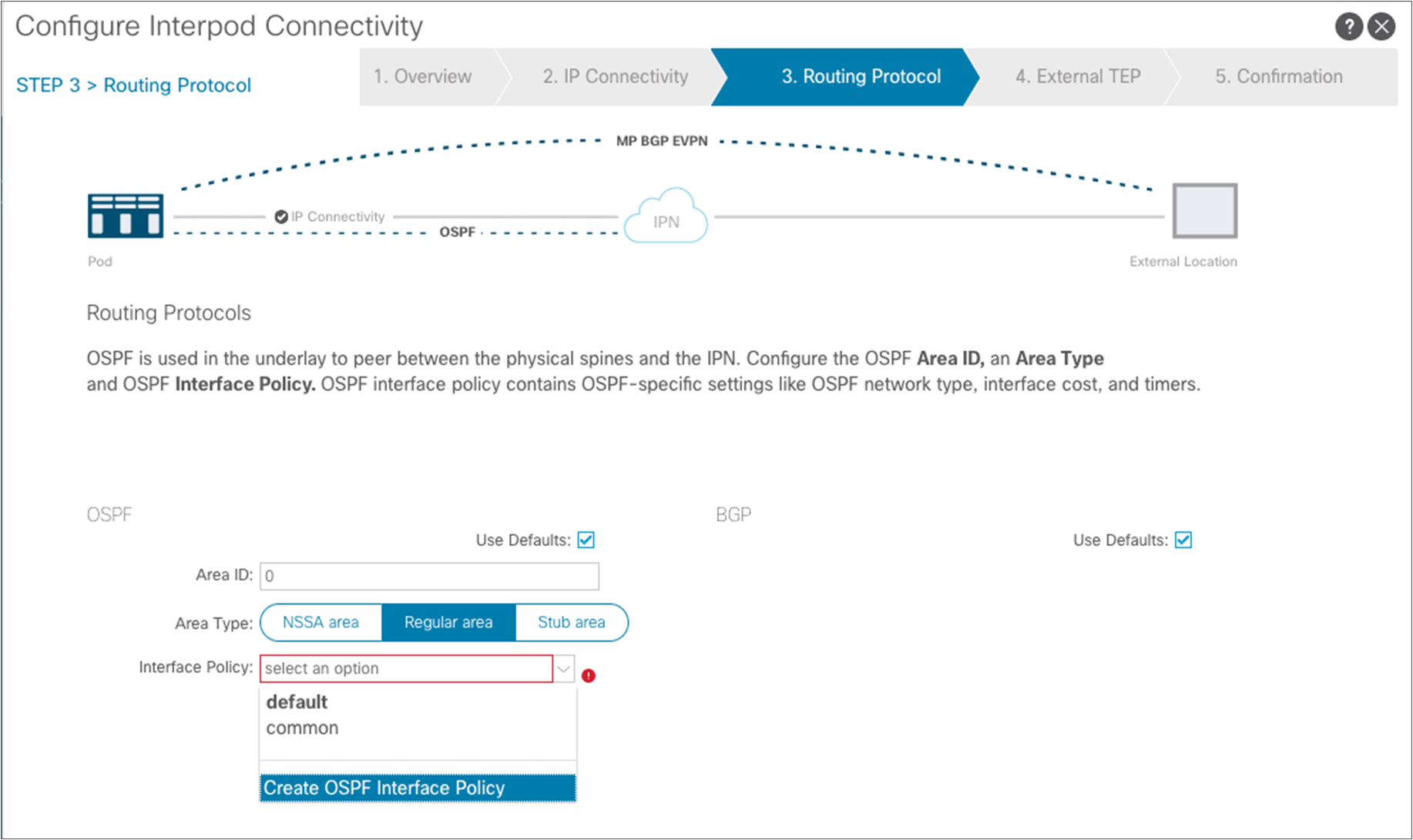
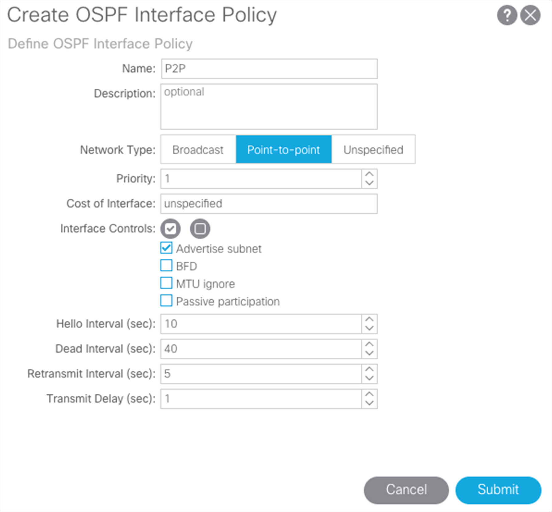
As shown above, another requirement is to create a specific OSPF Interface Policy: in our example, we want to ensure that the policy specifies point-to-point as the network type of the OSPF adjacencies.
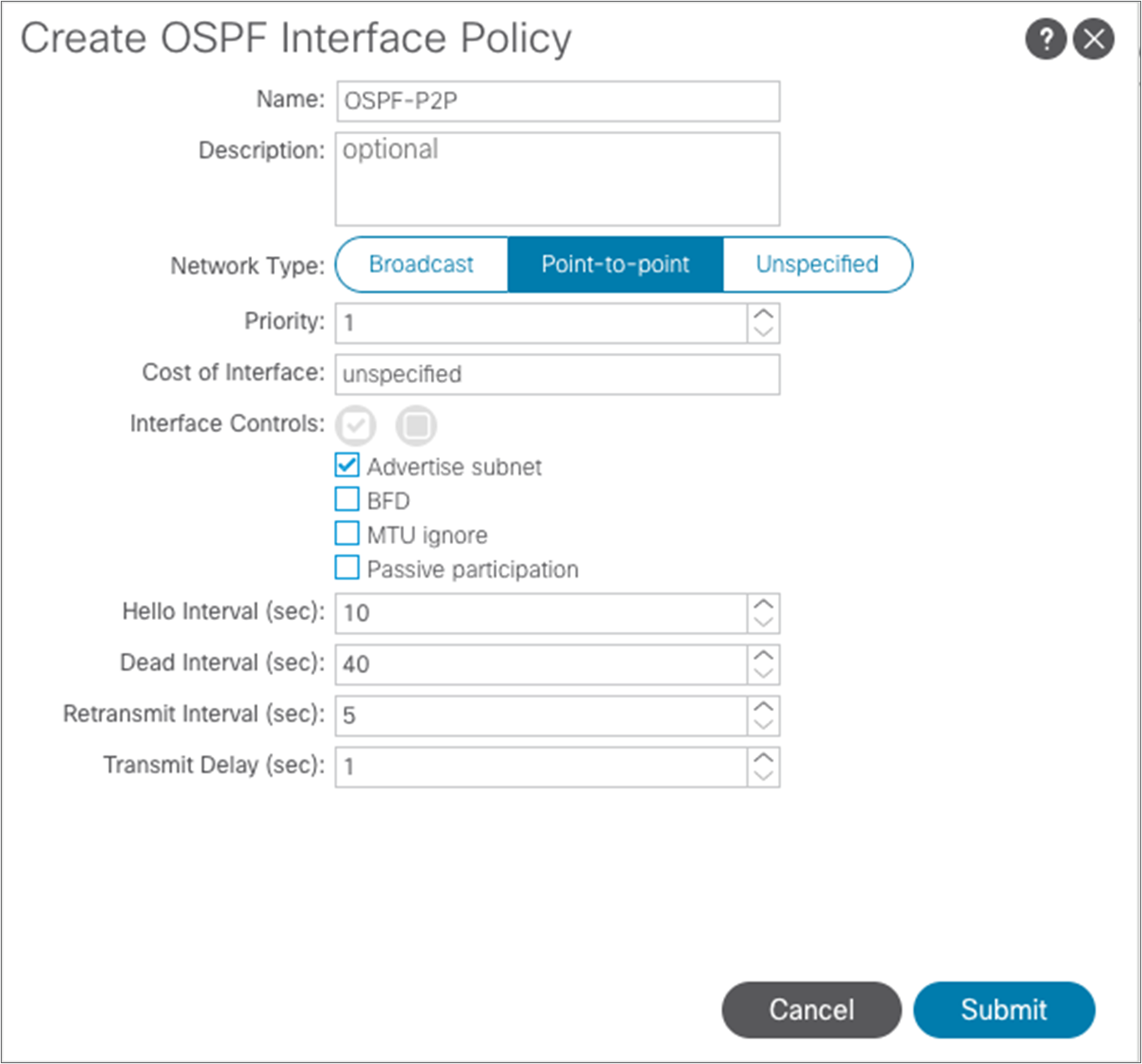
After submitting the OSPF interface policy configuration, click “Next” to move to the following step.
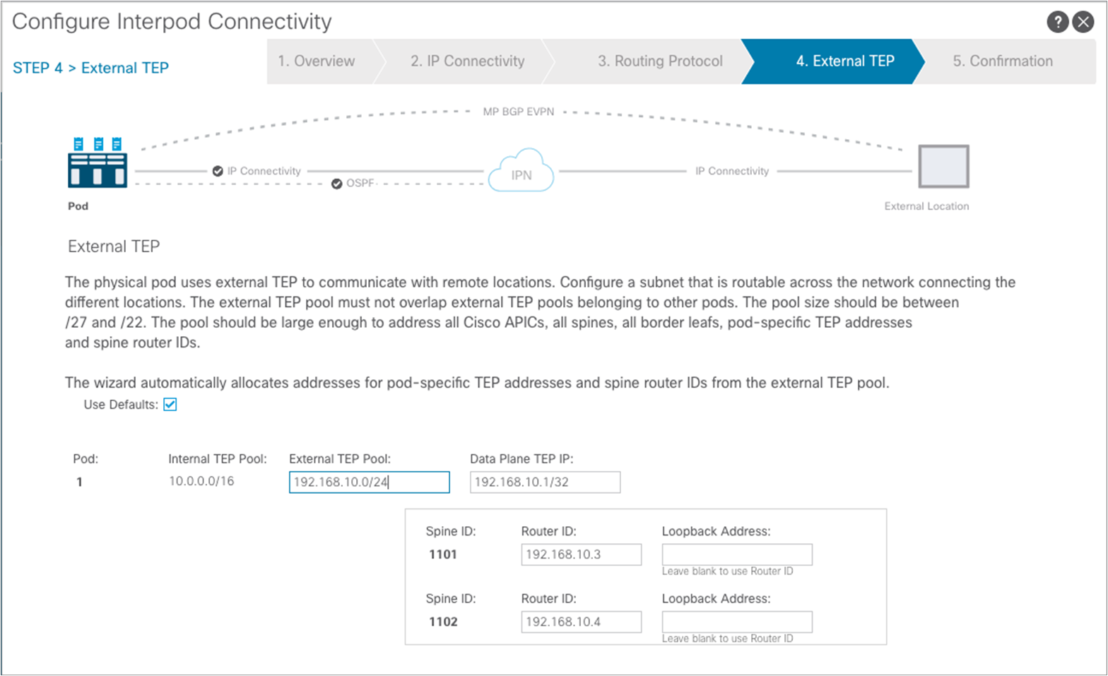
In this step you need to specify an “External TEP pool,” which must be routable across the IPN connecting the pods; this is used to dynamically assign a unique Router-ID address to each spine node and a common Data Plane TEP IP address to all the spines in the pod (anycast TEP). The Router-ID will be used to establish MP-BGP EVPN peerings with the spine nodes in remote pods, whereas the anycast TEP address represents the next-hop for all the EVPN prefixes (MAC and IP addresses for locally discovered endpoints) advertised between pods. Then click “Next” to move to the final step.
Note: It is best practice to specify a network prefix different from the one used to address the physical connection between the spine nodes and the IPN and between the IPN nodes. This simplifies troubleshooting, because it is easier to track those IP addresses that are used for different purposes. Also, the mask for the external TEP pool subnet must have a length of between /22 and /29.
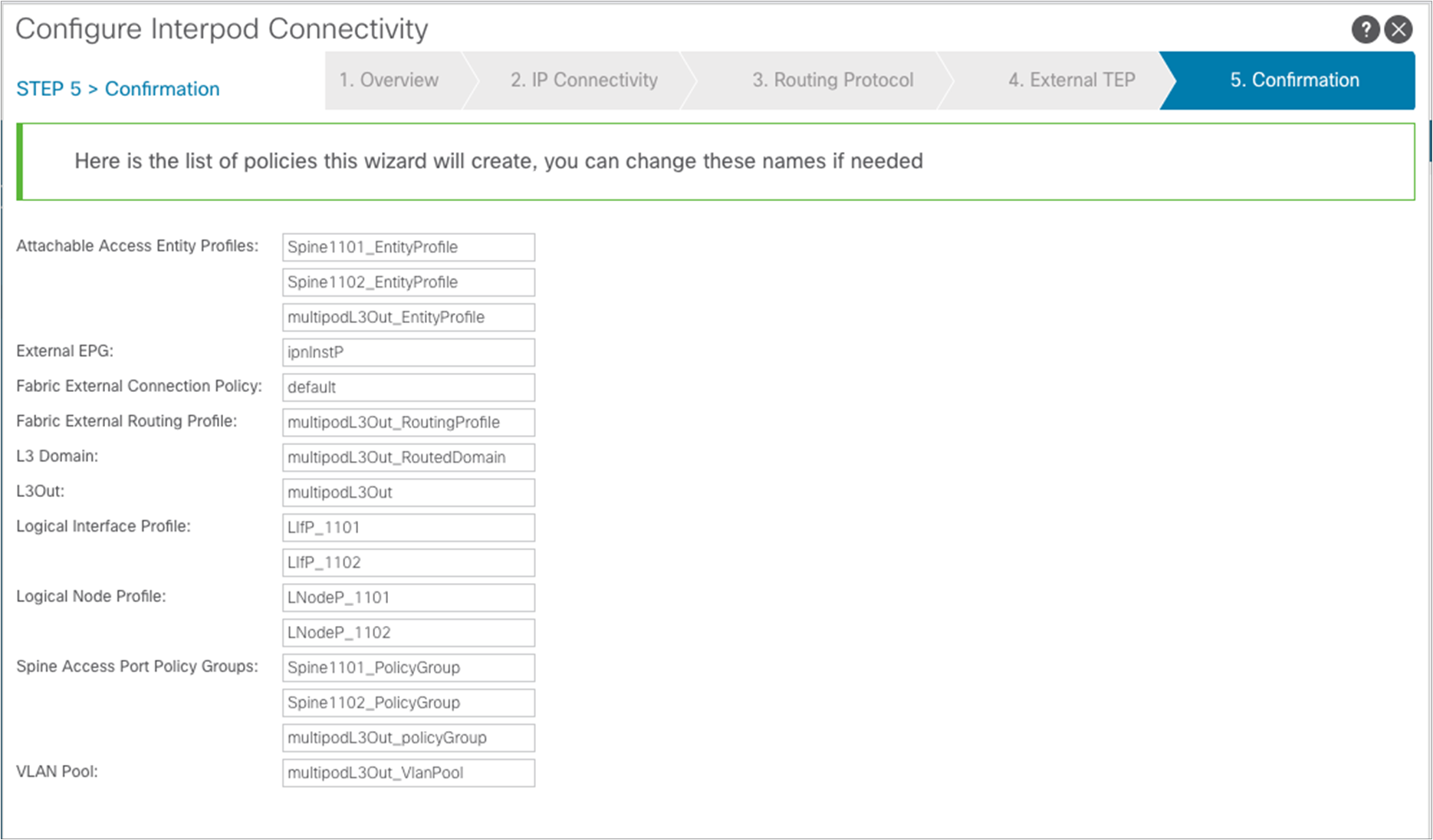
A confirmation page is finally displayed, showing all the configuration objects that are going to be created as the result of the simple steps taken during the wizard configuration. Those are all the objects that otherwise must be manually configured, as described in Appendix. Click “Finish.”
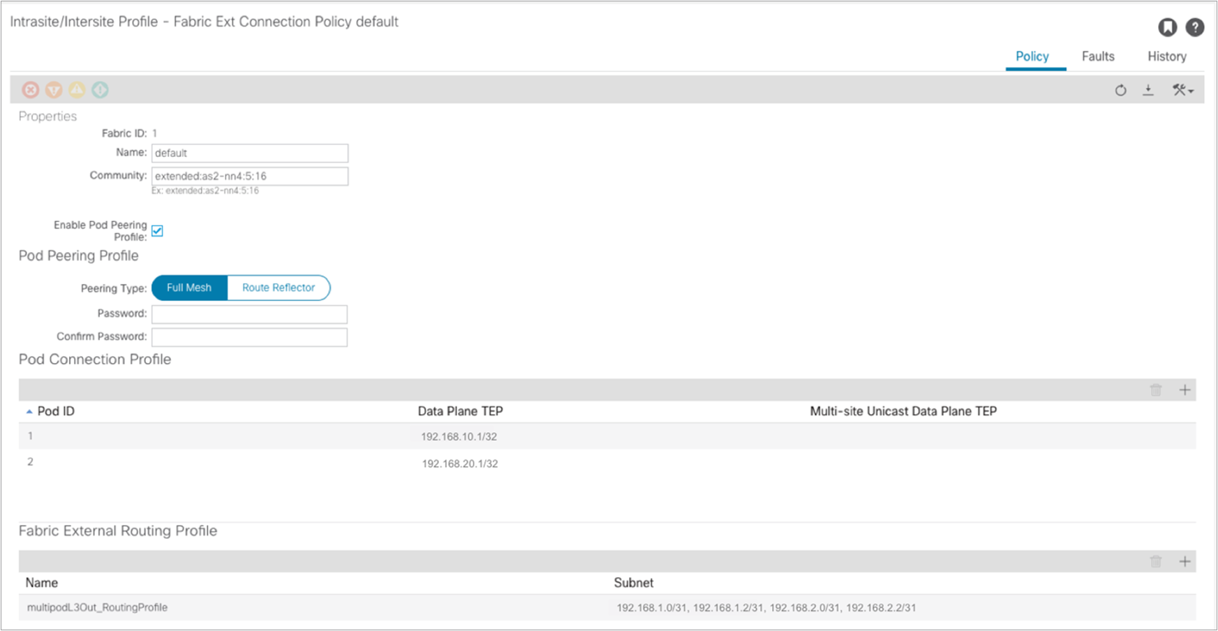
A summary window is shown; at this point the spines in Pod1 should successfully have established OSPF peering with the directly connected IPN devices. It is worth pointing out how at this point also a “Fabric External Connection Policy” has been dynamically created. This can be seen as part of the “infra” tenant configuration:
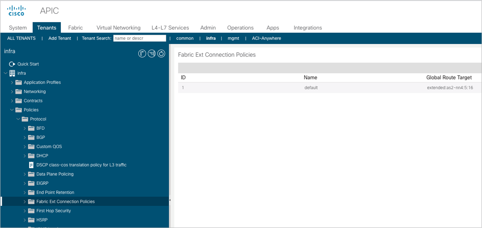
Selecting the specific policy, we can display the following information:
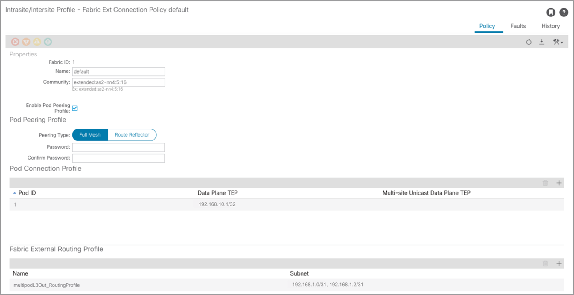
A community value is automatically assigned to allow the exchange of EVPN prefixes with the spines in remote pods. Also, the EVPN peering type is configured, by default, for full mesh. It is strongly recommended to keep the full mesh configuration for a Multi-Pod fabric that has up to three pods. External route reflectors could then be introduced, if really desired, for a deployment with a larger number of pods (the configuration of E-RRs is not covered in this paper). Finally, the data-plane TEP (anycast TEP) assigned to all the spines in the pod is also displayed here, together with the IP prefixes assigned to the underlay connection between the spine nodes and the IPN devices (this is needed to ensure those prefixes are then redistributed into the IS-IS control plane running inside each pod).
If at this point you are ready to add a second pod, you can start the wizard workflow simply by selecting “Add Physical Pod.”
Note: A second pod can also be added later on by going back to Fabric à Inventory and selecting “Add Pod.”
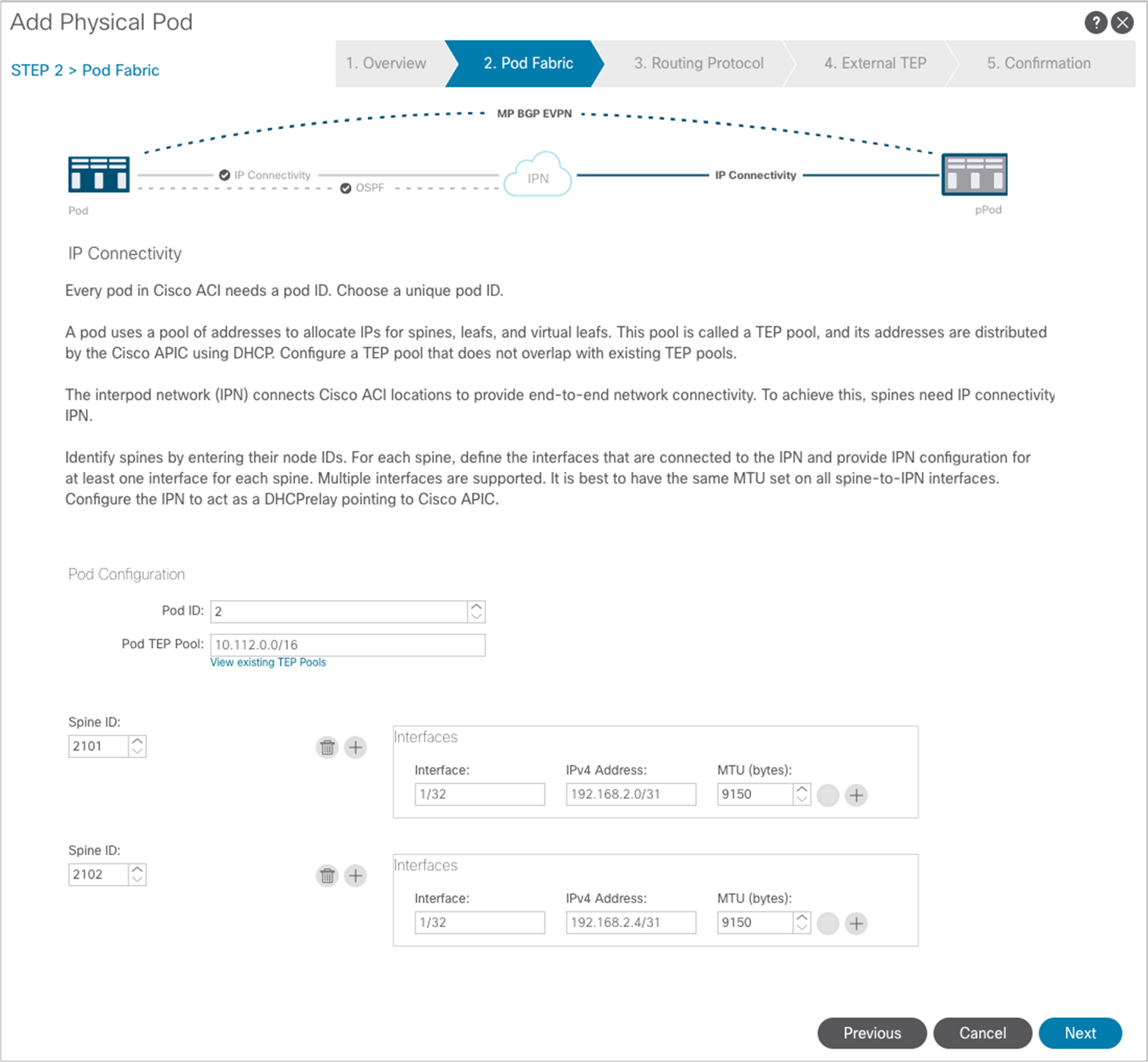
In the “Add Physical Pod” window, specify the spine nodes in Pod2 and configure their interfaces connected to the IPN, similarly to how it was done for Pod1. At the end click “Next.”
Notice above how the wizard assumes that the same OSPF area 0 (“backbone”) is extended across the pods through the IPN. As a consequence, the only required configuration in this window is the selection of the same OSPF Interface Policy already used for Pod1. Click “Next” to move to the next page.
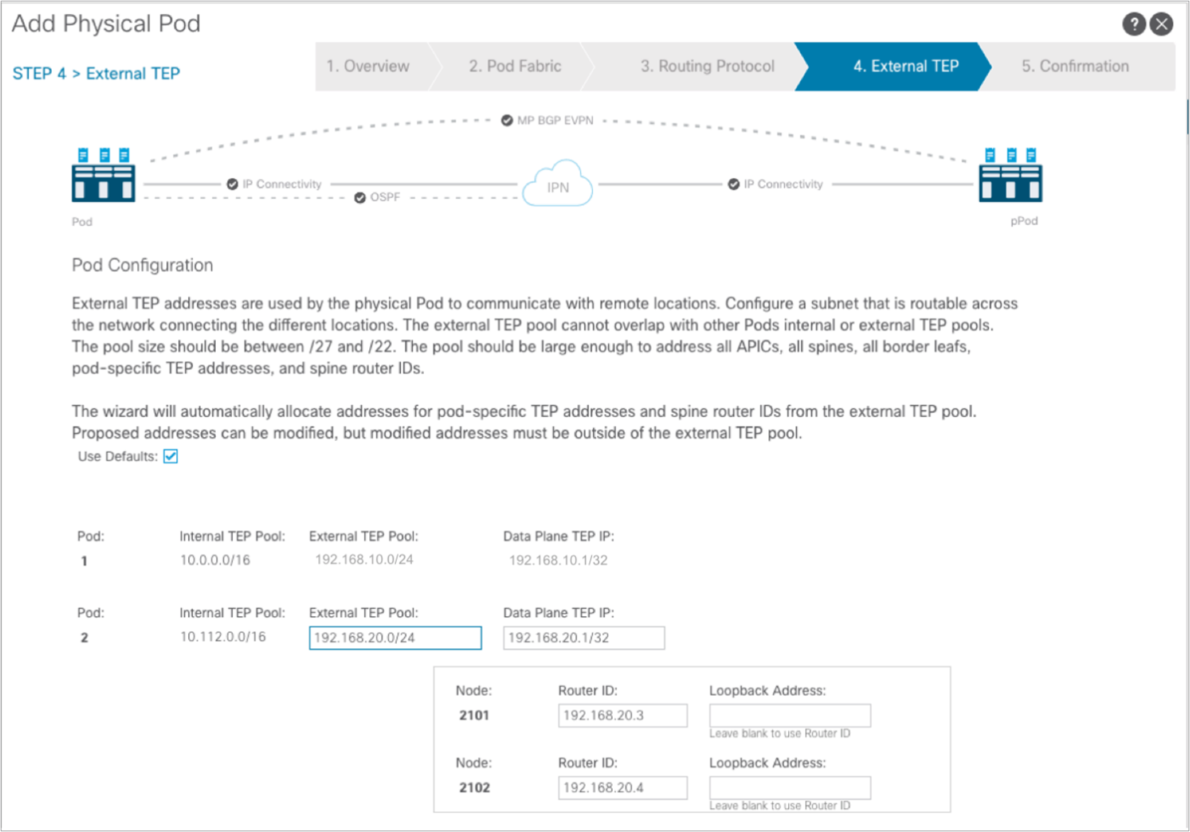
A separate External TEP pool 192.168.20.0/24 can be used for Pod2, as shown above. Click “Next.”
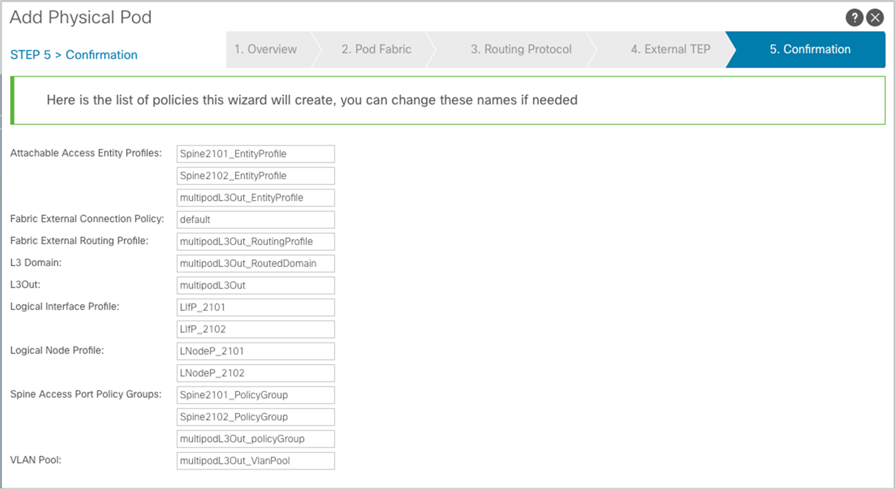
The confirmation page is displayed showing all the objects that are going to be created. Click “Finish.”
At this point, all the infra configuration required to connect Pod2 as well to the IPN is completed, and the auto-discovery process can start to ensure that configuration can be dynamically provisioned to all the spine and leaf nodes in Pod2.
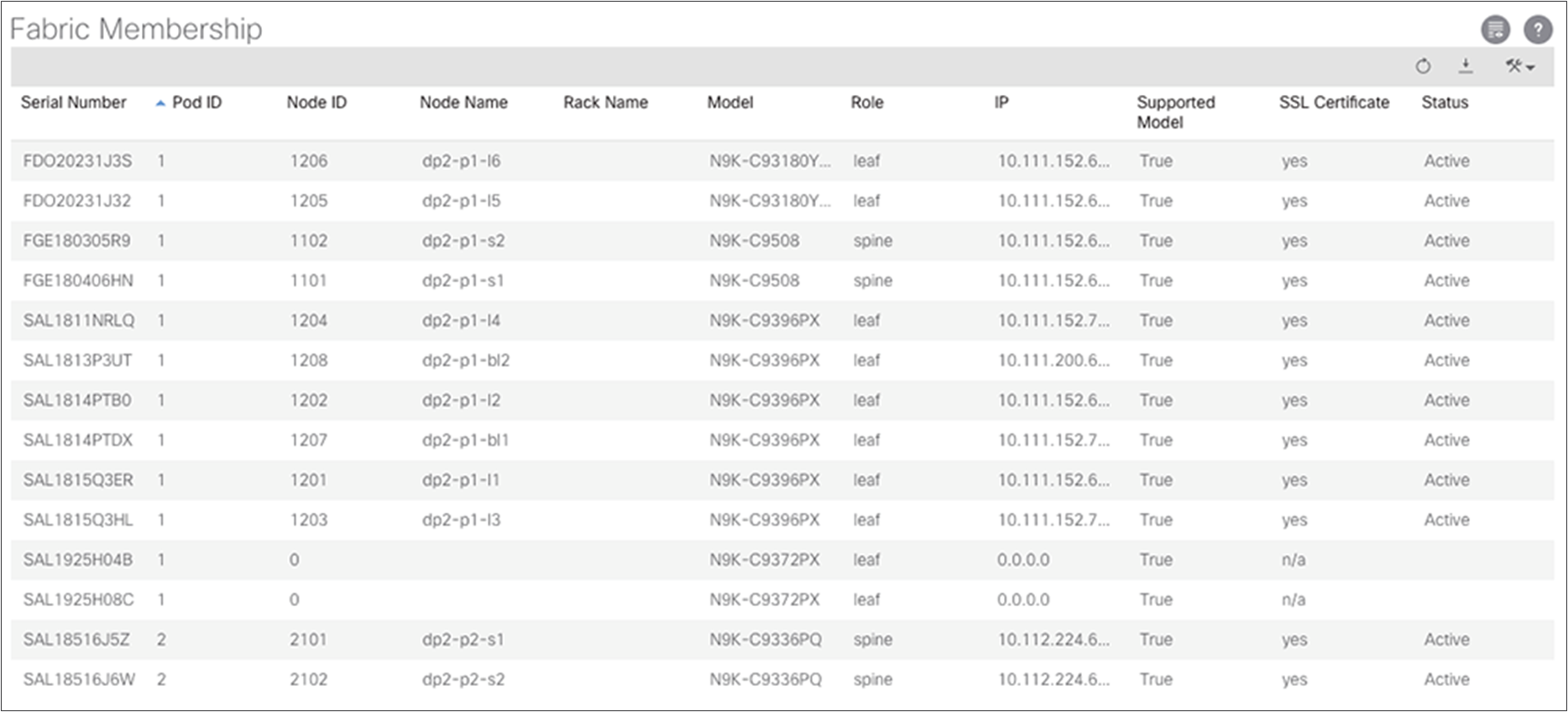
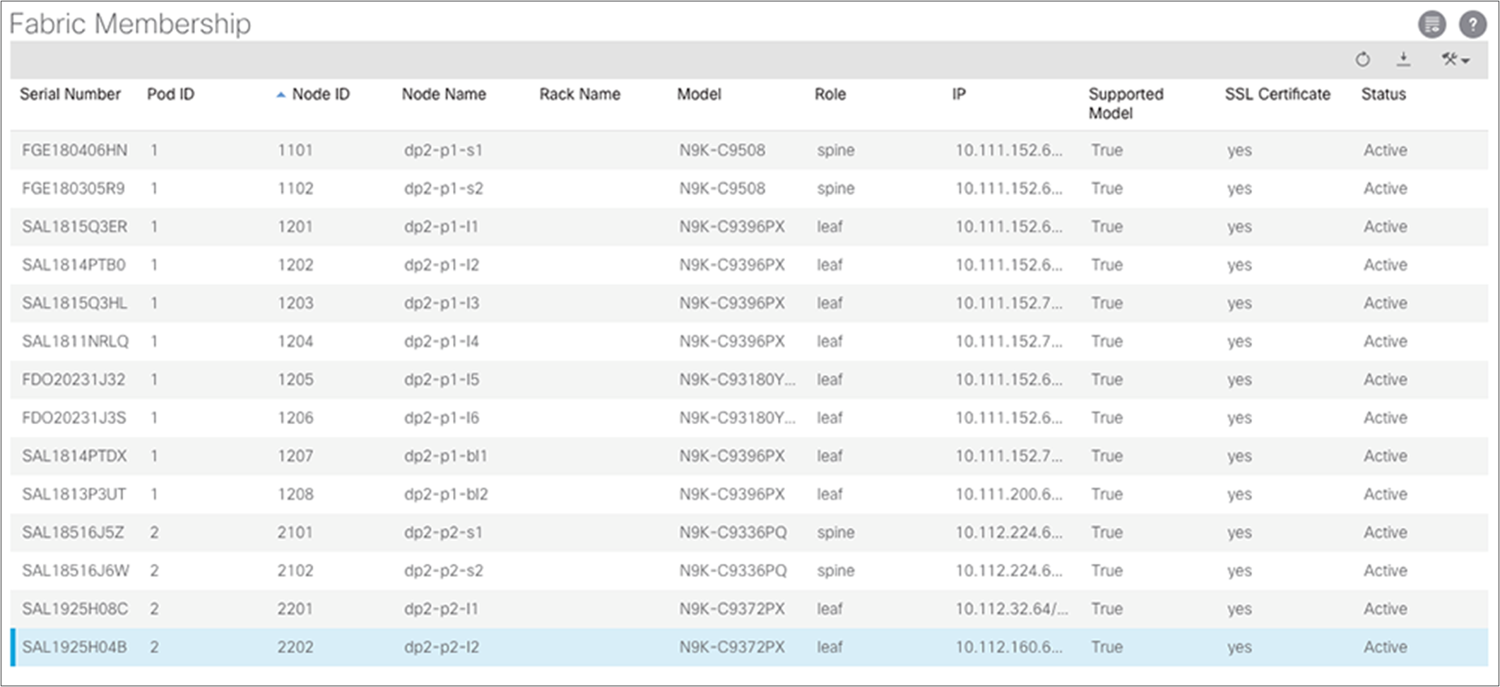
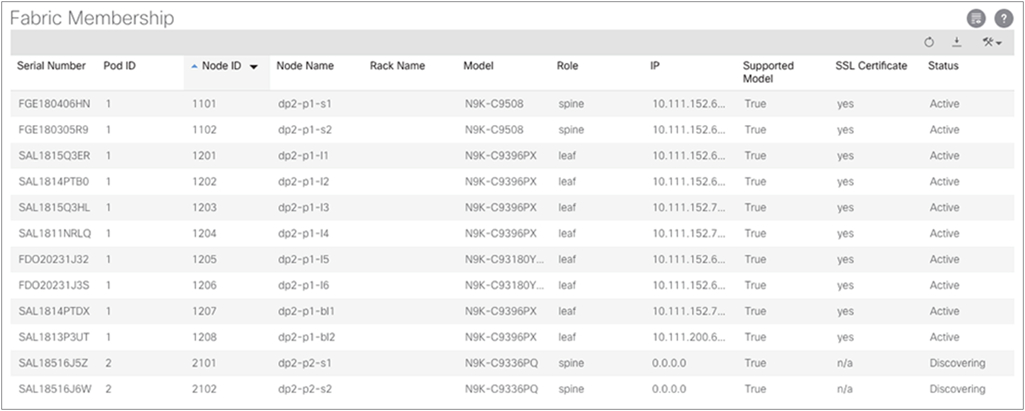
In order for this process to be completed, it is required to ensure that all the nodes in Pod2 are registered as part of the fabric. This can be done from Fabric à Inventory accessing the Fabric Membership table.
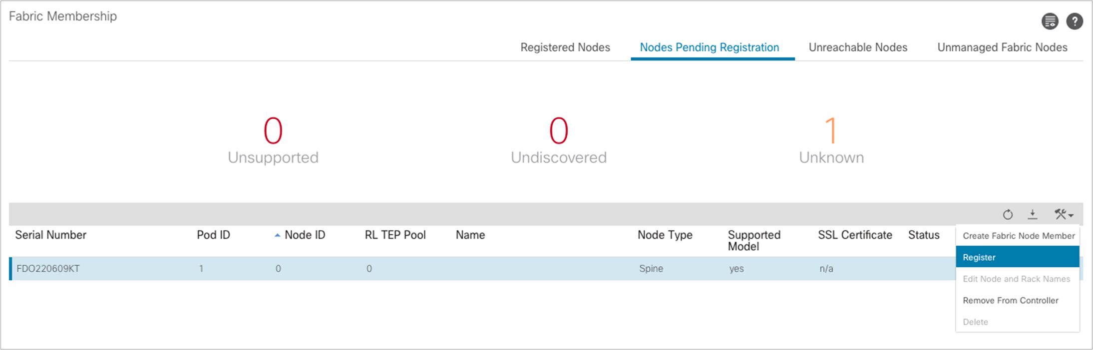
As shown above, the spine nodes in Pod2 should dynamically appear as part of the “Nodes Pending Registration” tab. At this point it is possible to select each node displayed there, identify the role it should have, based on its unique serial number, and register it as part of the fabric.
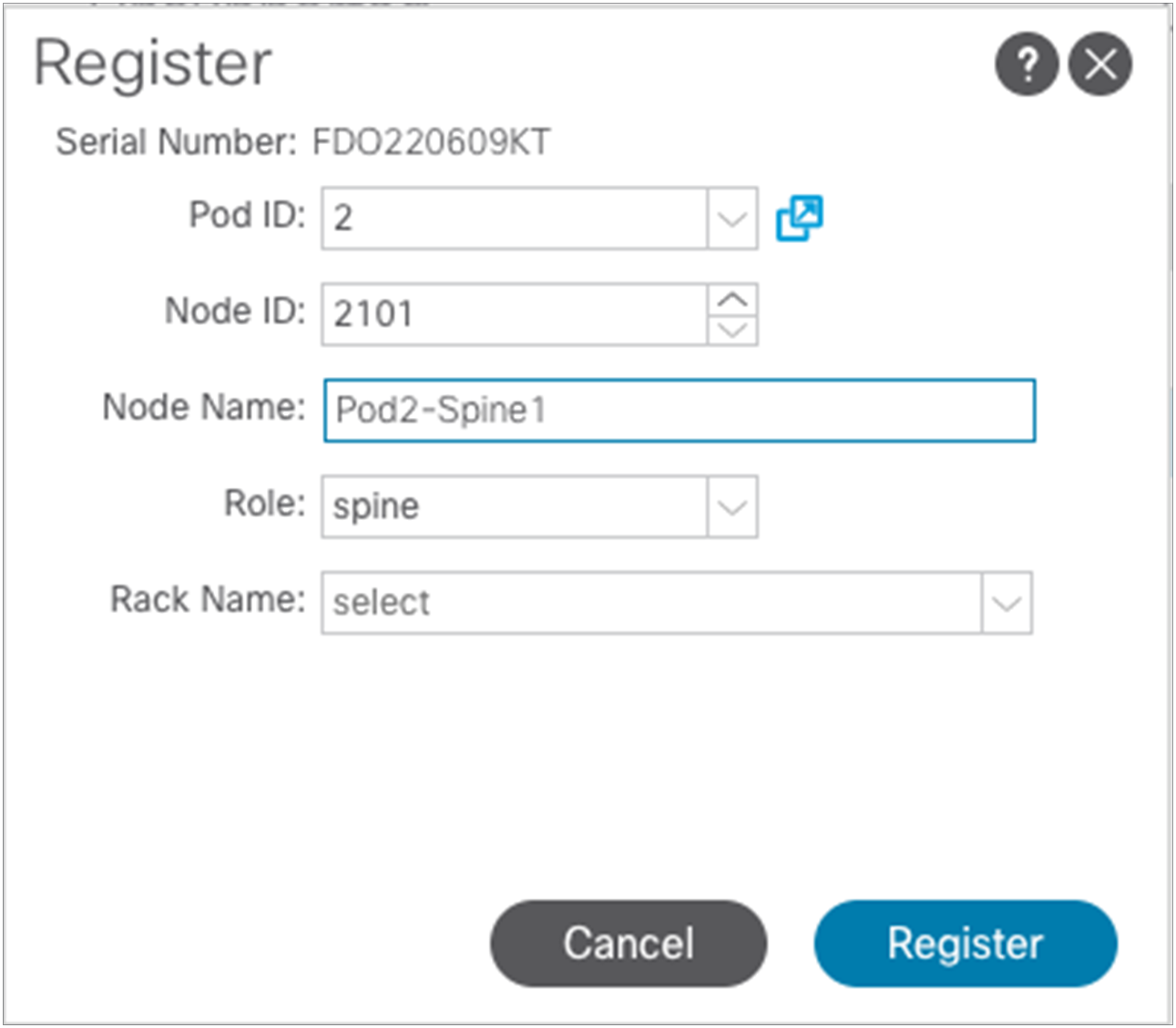
Above is the information required to register a node as the first spine of Pod2. After clicking “Register,” the registration process will start and the spine will receive the required configuration from the APIC nodes connected in Pod1. Once the auto-provisioning process is completed for the spine, it is possible to repeat the same registration step for all the other nodes in Pod2.
At the end of the registration process for Pod2, it is also possible to verify that the fabric’s External Connection Policy in the “infra” tenant has been dynamically updated to include the information relative to Pod2.
As a last step, it is then possible to run the setup script on the two APIC nodes connected to the leaf nodes in Pod2, using the information displayed in Table 1. At the end of this process, the two APIC nodes will join the cluster with the three nodes already deployed in Pod1.
Follow the steps in this section to verify the preceding configuration.
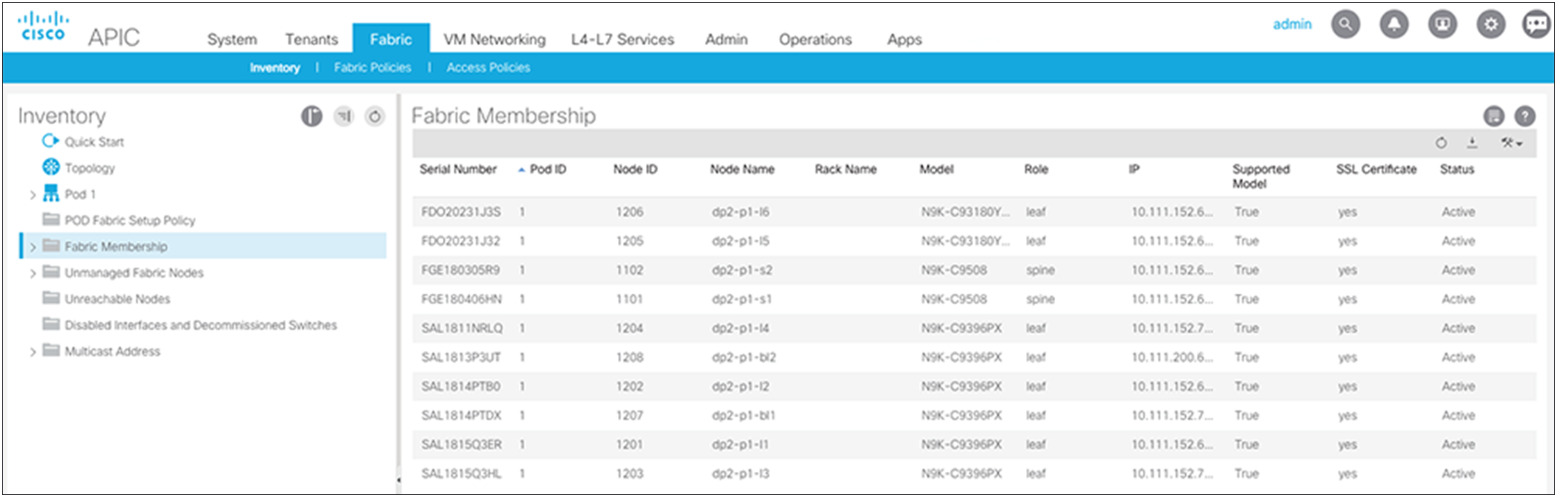
Verifying fabric membership and topology
Return to the Fabric Membership list and verify that the spine switches have their TEP addresses, which allowed discovery of the connected leaf switches.
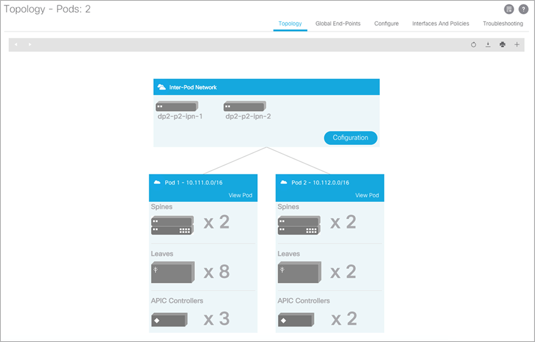
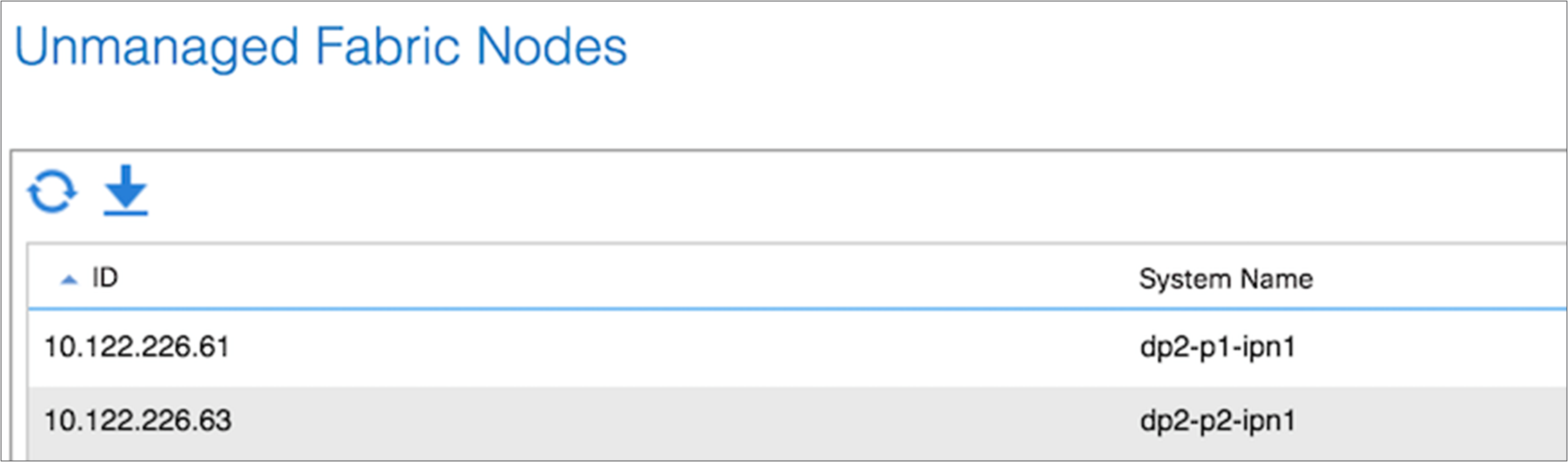
After the discovered leaf switches are acknowledged in the fabric, the Topology screen should show all your switches. If all your IPN switches do not appear on in the IPN topology, you can verify their connectivity under Unmanaged Fabric Nodes.
To verify the IPN, first check the OSPF adjacency status between the Cisco Nexus 7000 Series Switch and the adjacent spine switches.
dp2-p1-ipn1# show ip ospf neighbors vrf IPN-1
OSPF Process ID IPN VRF IPN-1
Total number of neighbors: 4
Neighbor ID Pri State Up Time Address Interface
192.168.10.3 1 FULL/ - 02:46:04 192.168.1.0 Eth1/7.4
192.168.10.4 1 FULL/ - 02:46:02 192.168.1.4 Eth1/8.4
2.2.2.1 1 FULL/ - 1w6d 192.168.12.1 Po910
dp2-p1-ipn1#
With the adjacency established, you should see the learned routes into this VRF instance from the adjacent spine switches.
dp2-p1-ipn1# show ip route vrf IPN-1
IP Route Table for VRF "IPN-1"
'*' denotes best ucast next-hop
'**' denotes best mcast next-hop
'[x/y]' denotes [preference/metric]
'%<string>' in via output denotes VRF <string>
10.111.0.0/16, ubest/mbest: 2/0
*via 192.168.1.0, Eth1/7.4, [110/20], 02:44:02, ospf-IPN, type-2
*via 192.168.1.4, Eth1/8.4, [110/20], 02:44:02, ospf-IPN, type-2
10.111.0.1/32, ubest/mbest: 2/0
*via 192.168.1.0, Eth1/7.4, [110/20], 02:44:02, ospf-IPN, type-2
*via 192.168.1.4, Eth1/8.4, [110/20], 02:44:02, ospf-IPN, type-2
10.111.0.2/32, ubest/mbest: 2/0
*via 192.168.1.0, Eth1/7.4, [110/20], 02:44:02, ospf-IPN, type-2
*via 192.168.1.4, Eth1/8.4, [110/20], 02:44:02, ospf-IPN, type-2
10.111.0.3/32, ubest/mbest: 2/0
*via 192.168.1.0, Eth1/7.4, [110/20], 02:44:02, ospf-IPN, type-2
*via 192.168.1.4, Eth1/8.4, [110/20], 02:44:02, ospf-IPN, type-2
10.111.0.4/32, ubest/mbest: 1/0
*via 192.168.12.1, Po910, [110/20], 02:25:25, ospf-IPN, type-2
10.111.0.5/32, ubest/mbest: 1/0
*via 192.168.12.1, Po910, [110/20], 02:25:25, ospf-IPN, type-2
10.111.0.33/32, ubest/mbest: 2/0
*via 192.168.1.0, Eth1/7.4, [110/20], 02:44:02, ospf-IPN, type-2
*via 192.168.1.4, Eth1/8.4, [110/20], 02:44:02, ospf-IPN, type-2
10.111.0.34/32, ubest/mbest: 2/0
*via 192.168.1.0, Eth1/7.4, [110/20], 02:44:02, ospf-IPN, type-2
*via 192.168.1.4, Eth1/8.4, [110/20], 02:44:02, ospf-IPN, type-2
10.111.0.35/32, ubest/mbest: 2/0
*via 192.168.1.0, Eth1/7.4, [110/20], 02:44:02, ospf-IPN, type-2
*via 192.168.1.4, Eth1/8.4, [110/20], 02:44:02, ospf-IPN, type-2
10.111.152.63/32, ubest/mbest: 1/0
*via 192.168.1.0, Eth1/7.4, [110/2], 02:44:07, ospf-IPN, intra
10.111.152.64/32, ubest/mbest: 1/0
*via 192.168.1.4, Eth1/8.4, [110/2], 02:44:02, ospf-IPN, intra
10.112.0.0/16, ubest/mbest: 1/0
*via 192.168.12.1, Po910, [110/20], 02:25:25, ospf-IPN, type-2
10.112.0.33/32, ubest/mbest: 1/0
*via 192.168.12.1, Po910, [110/20], 02:25:25, ospf-IPN, type-2
10.112.0.34/32, ubest/mbest: 1/0
*via 192.168.12.1, Po910, [110/20], 02:25:25, ospf-IPN, type-2
10.112.0.35/32, ubest/mbest: 1/0
*via 192.168.12.1, Po910, [110/20], 02:25:25, ospf-IPN, type-2
10.112.224.64/32, ubest/mbest: 1/0
*via 192.168.12.1, Po910, [110/3], 02:25:25, ospf-IPN, intra
10.112.224.65/32, ubest/mbest: 1/0
*via 192.168.12.1, Po910, [110/3], 02:25:22, ospf-IPN, intra
192.168.1.0/31, ubest/mbest: 1/0, attached
*via 192.168.1.1, Eth1/7.4, [0/0], 03:28:46, direct
192.168.1.1/32, ubest/mbest: 1/0, attached
*via 192.168.1.1, Eth1/7.4, [0/0], 03:28:46, local
192.168.1.4/31, ubest/mbest: 1/0, attached
*via 192.168.1.5, Eth1/8.4, [0/0], 03:28:53, direct
192.168.1.5/32, ubest/mbest: 1/0, attached
*via 192.168.1.5, Eth1/8.4, [0/0], 03:28:53, local
192.168.10.0/24, ubest/mbest: 1/0
*via 192.168.1.0, Eth1/7.4, [110/20], 02:44:02, ospf-IPN, type-2
*via 192.168.1.4, Eth1/8.4, [110/20], 02:44:02, ospf-IPN, type-2
192.168.10.3/32, ubest/mbest: 1/0
*via 192.168.1.0, Eth1/7.4, [110/2], 02:44:07, ospf-IPN, intra
192.168.10.4/32, ubest/mbest: 1/0
*via 192.168.1.4, Eth1/8.4, [110/2], 02:44:02, ospf-IPN, intra
192.168.2.0/31, ubest/mbest: 1/0
*via 192.168.12.1, Po910, [110/2], 03:30:46, ospf-IPN, intra
192.168.2.4/31, ubest/mbest: 1/0
*via 192.168.12.1, Po910, [110/2], 03:30:53, ospf-IPN, intra
192.168.20.0/24, ubest/mbest: 1/0
*via 192.168.12.1, Po910, [110/20], 02:25:25, ospf-IPN, type-2
192.168.20.3/32, ubest/mbest: 1/0
*via 192.168.12.1, Po910, [110/20], 02:25:25, ospf-IPN, type-2
192.168.20.4/32, ubest/mbest: 1/0
*via 192.168.12.1, Po910, [110/20], 02:25:25, ospf-IPN, type-2
dp2-p1-ipn1#
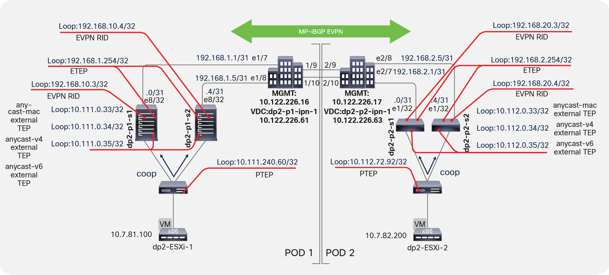
Verifying external TEP interfaces on spine switches
Using virtual shell (VSH), verify all the interfaces on the spine switches. The Multi-Pod design introduces some new external TEP addresses used in the data plane as the external anycast TEP addresses (MAC, IPv4, and IPv6 addresses); see Figure 5. These will be discussed in the following sections as relevant.
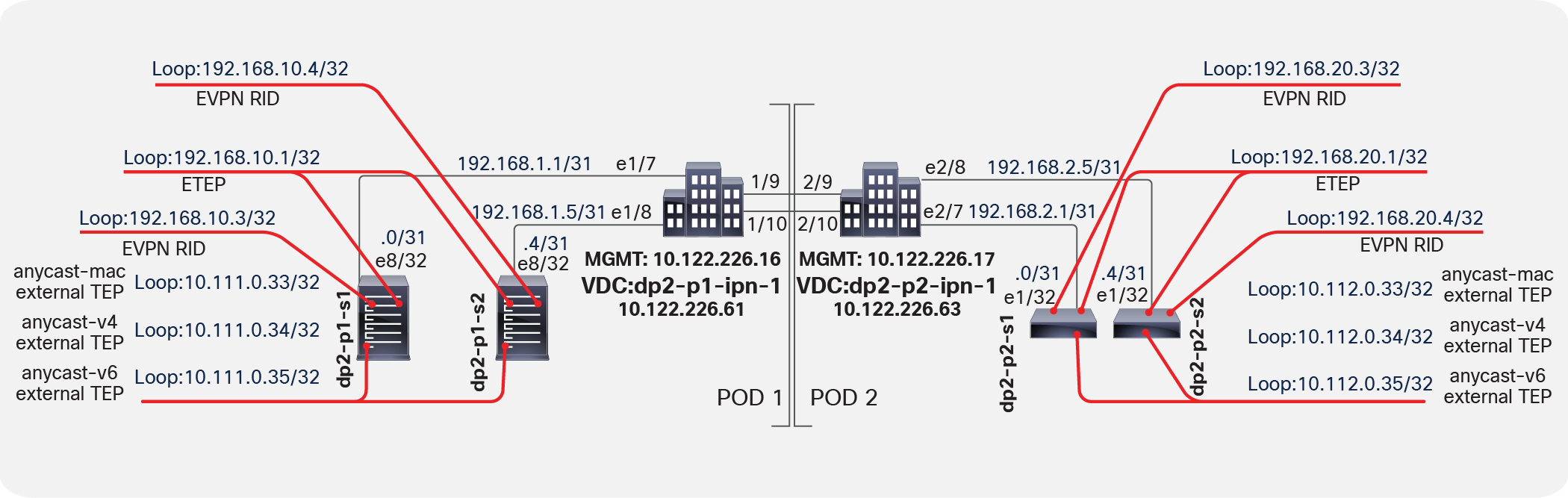
Verifying external TEP interfaces on spine switches
Note: The next-hop for the EVPN prefixes (MAC and IP addresses for the endpoint) exchanged between pods is always the anycast ETEP address defined for the spines of each pod. However, because of specific implementation reasons, data-plane traffic (for L2, IPv4, and IPv6 communication) is always encapsulated to a specific anycast-address part of the original TEP pool (those are the “anycast-mac,” “anycast-v4,” and “anycast-v6” addresses displayed in Figure 5, above).
On each spine device, you can verify the MP-BGP EVPN peering and route advertisements. The learned routes represent endpoints learned between the two pods (that is, host MAC and IP address information). In MP-BGP EVPN, these types of routes are called Route Type: 2–Host MAC/IP. In the summary command, the number of learned routes will increase as the number of endpoints in the fabric increase.
Note that the router IDs selected in the policy configuration are the MP-BGP EVPN Router-IDs (EVPN-RID) assigned by the wizard workflow from the specified external TEP pool. These IP addresses are used to establish MP-BGP EVPN peering. The same fabric BGP process is extended across pods, thus making this MP-iBGP EVPN (Figure 6). As mentioned previously, the Data-Plane ETEP (DP-ETEP) address is used as the next hop in host route advertisement between pods.
This verification process assumes that you have configured the fabric profile with an MP-BGP Autonomous System Number (ASN). Otherwise, the BGP process will not be running.
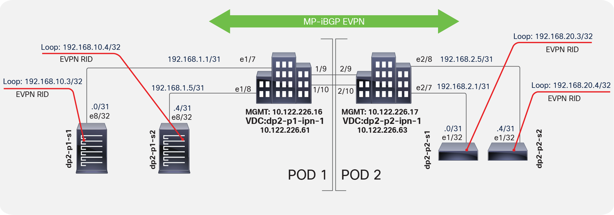
Verifying spine MP-BGP EVPN
dp2-p1-s1# show bgp l2vpn evpn summary vrf overlay-1
BGP summary information for VRF overlay-1, address family L2VPN EVPN
BGP router identifier 192.168.10.3, local AS number 65000
BGP table version is 806, L2VPN EVPN config peers 2, capable peers 2
57 network entries and 73 paths using 10140 bytes of memory
BGP attribute entries [6/864], BGP AS path entries [0/0]
BGP community entries [0/0], BGP clusterlist entries [0/0]
Neighbor V AS MsgRcvd MsgSent TblVer InQ OutQ Up/Down State/PfxRcd
192.168.20.3 4 65000 35723 36745 806 0 0 1w5d 13
192.168.20.4 4 65000 35725 36744 806 0 0 1w5d 13
dp2-p1-s1#
The host route shown in Figure 7 uses the endpoint MAC address and is taken from a remote Pod2 spine switch, with the host route being advertised from a Pod1 spine switch.
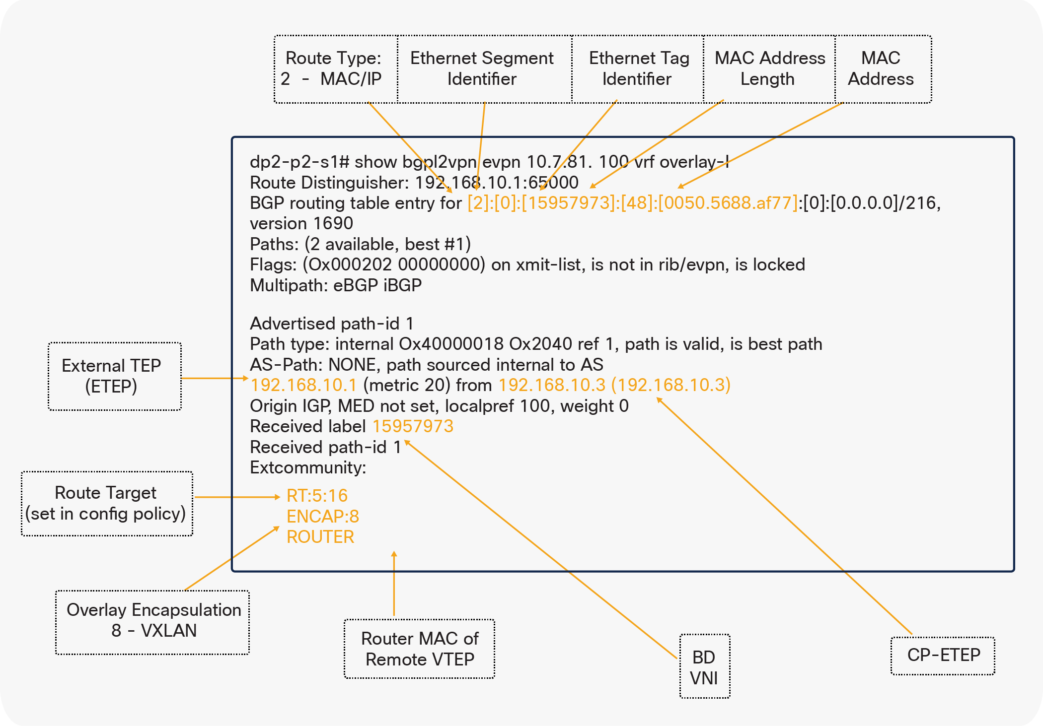
Host route with endpoint MAC address
The host route shown in Figure 8 uses the endpoint IP address and is taken from a remote Pod2 spine switch, with the host route being advertised from a Pod1 spine switch.
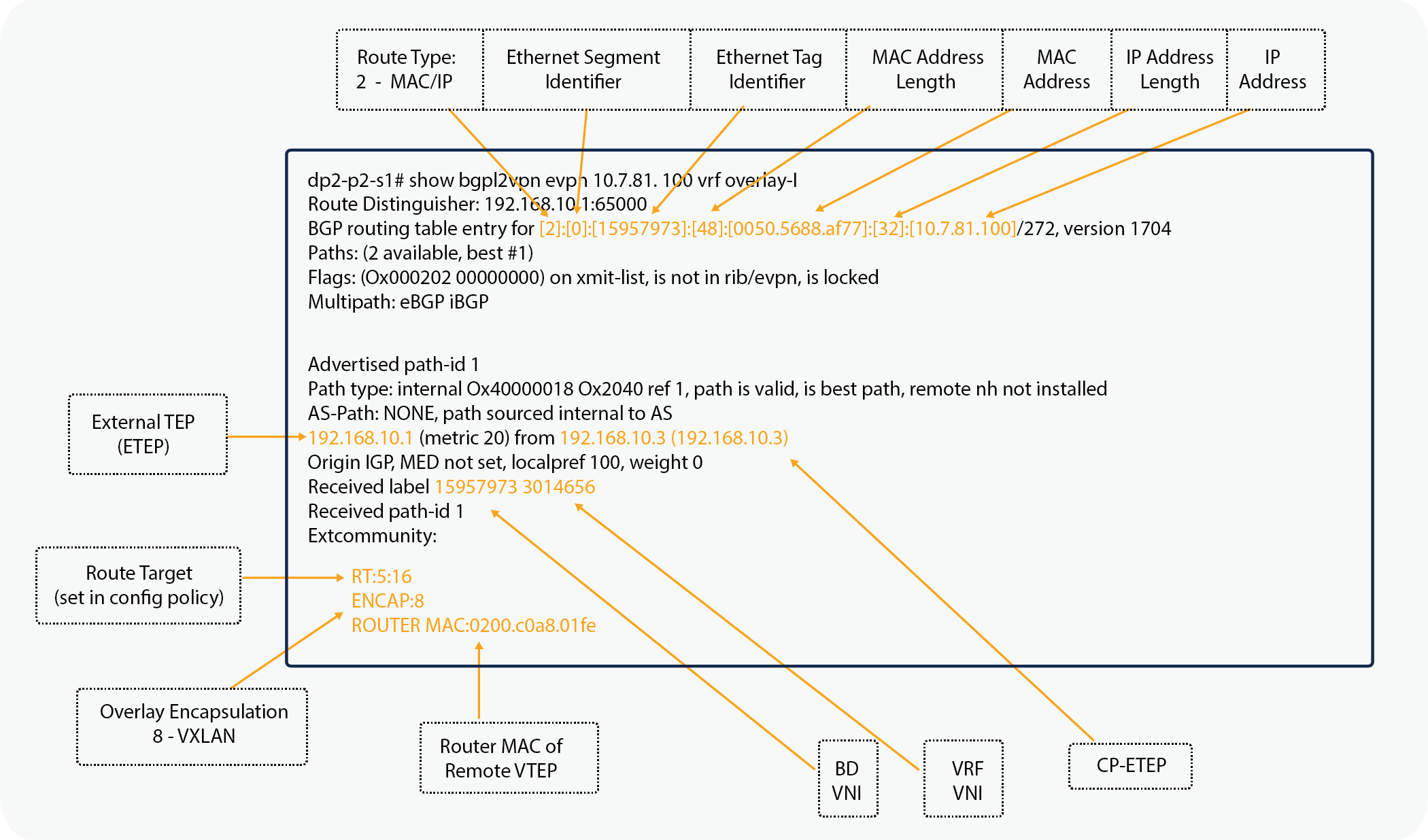
Remote Pod2 Endpoint IP address
Note that the router MAC address for the EVPN routes is derived from the VDC and system MAC address of the advertising spine switch.
dp2-p1-s1# vsh -c 'show vdc'
vdc_id vdc_name state mac type lc
------ -------- ----- ---------- --------- ------
1 dp2-p1-s1 active a8:0c:0d:96:c1:bf Ethernet m1 f1 m1xl m2xl
dp2-p1-s1#
Verifying the COOP database entry
On the remote spine switch, you can verify the council of oracles protocol and Council or Oracles Protocol (COOP) database entry and check that the entry is known through the proxy tunnel established between the spine switches in different pods. Also note that the ETEP, when used for MP-iBGP EVPN, is used by COOP to identify a remote pod's set of anycast addresses.
dp2-p2-s1# show coop internal info ip-db
<snip>
------------------------------
IP address : 10.7.81.100
Vrf : 3014656
Flags : 0x2
EP bd vnid : 15957973
EP mac : 00:50:56:88:AF:77
Publisher Id : 192.168.10.1
Record timestamp : 01 01 1970 00:00:00 0
Publish timestamp : 01 01 1970 00:00:00 0
Seq No: 0
Remote publish timestamp: 09 15 2016 12:35:54 723878748
URIB Tunnel Info
Num tunnels : 1
Tunnel address : 10.111.0.34
Tunnel ref count : 1
------------------------------
<snip>
dp2-p2-s1#
Figure 9 shows two virtual machines on two VMware ESXi hosts: one in each pod. Initially, each leaf switch knows nothing about the remote endpoints. This behavior is normal and expected. However, each spine switch in both pods knows about the endpoints through MP-iBGP EVPN and populates their COOP databases accordingly.
Building Dynamic Tunnels
When the virtual machine in Pod1 starts a new communication with the virtual machine in Pod2, the leaf switch directs traffic to its local spine proxy switch. The local spine switch sees the remote endpoint learned by MP-iBGP EVPN in its COOP database. It then sets the DIPO to the anycast proxy address of the remote pod spine switch. The traffic is redirected to the IPN because the anycast TEP next hop will be known through the OSPF peering. Note that traffic is never sent from a spine proxy switch in one pod directly to a leaf switch in a different pod.
The remote spine switch receives traffic and determines whether the inner destination endpoint is local. It then sends the traffic to the appropriate leaf switch. During this process, the source endpoint and the source Physical TEP (PTEP) or leaf switch are learned from the traffic flow. With this information, a dynamic tunnel is created from the Pod2 leaf switch to the Pod1 leaf switch for reverse traffic to use. The reverse traffic will build a complete dynamic tunnel between the two VTEPs or leaf switches. From that point onward, the two endpoints’ communication will be encapsulated leaf to leaf (VTEP to VTEP). The dynamic tunnels, as with normal tunnels in the fabric, are kept alive as long as there is communication between endpoints.
Dynamic tunnel: Same bridge domain and EPG
The listing for leaf endpoints before any traffic communication is shown here.
dp2-p1-l1:
dp2-p1-l1# show endpoint
Legend:
O - peer-attached H - vtep a - locally-aged S - static
V - vpc-attached p - peer-aged L - local M - span
s - static-arp B - bounce
+-----------------------------------+---------------+-----------------+--------------+-------------+
VLAN/ Encap MAC Address MAC Info/ Interface
Domain VLAN IP Address IP Info
+-----------------------------------+---------------+-----------------+--------------+-------------+
17 vlan-10 0078.88f0.e79b O tunnel43
mgmt:inb vlan-10 10.7.80.11 O tunnel43
16 vlan-1068 0050.5688.af77 L eth1/1
mtarking-T1:mtarking-VRF vlan-1068 10.7.81.100 L eth1/1
overlay-1 10.111.240.60 L lo0
overlay-1 10.111.152.68 L lo1
dp2-p1-l1#
dp2-p2-l1:
dp2-p2-l1# show endpoint
Legend:
O - peer-attached H - vtep a - locally-aged S - static
V - vpc-attached p - peer-aged L - local M - span
s - static-arp B - bounce
+-----------------------------------+---------------+-----------------+--------------+-------------+
VLAN/ Encap MAC Address MAC Info/ Interface
Domain VLAN IP Address IP Info
+-----------------------------------+---------------+-----------------+--------------+-------------+
13 vlan-1067 0050.5688.d6a6 L eth1/1
mtarking-T1:mtarking-VRF vlan-1067 10.7.82.200 L eth1/1
15 vlan-1068 0050.5688.caa9 L eth1/1
mtarking-T1:mtarking-VRF vlan-1068 10.7.81.200 L eth1/1
overlay-1 10.112.72.92 L lo0
dp2-p2-l1#
The dynamic tunnel created has the virtual machine in Pod1 (10.7.81.100) send a ping to the virtual machine in Pod2 (10.7.81.200).
dp2-p1-l1:
dp2-p1-l1# show endpoint
Legend:
O - peer-attached H - vtep a - locally-aged S - static
V - vpc-attached p - peer-aged L - local M - span
s - static-arp B - bounce
+-----------------------------------+---------------+-----------------+--------------+-------------+
VLAN/ Encap MAC Address MAC Info/ Interface
Domain VLAN IP Address IP Info
+-----------------------------------+---------------+-----------------+--------------+-------------+
17 vlan-10 0078.88f0.e79b O tunnel43
mgmt:inb vlan-10 10.7.80.11 O tunnel43
mtarking-T1:mtarking-VRF 10.7.81.200 tunnel44
15/mtarking-T1:mtarking-VRF vxlan-15957973 0050.5688.caa9 tunnel44
16 vlan-1068 0050.5688.af77 L eth1/1
mtarking-T1:mtarking-VRF vlan-1068 10.7.81.100 L eth1/1
overlay-1 10.111.240.60 L lo0
overlay-1 10.111.152.68 L lo1
dp2-p1-l1#
dp2-p1-l1# show interface tunnel44
Tunnel44 is up
MTU 9000 bytes, BW 0 Kbit
Transport protocol is in VRF "overlay-1"
Tunnel protocol/transport is ivxlan
Tunnel source 10.111.240.60/32 (lo0)
Tunnel destination 10.112.72.92
Last clearing of "show interface" counters never
Tx
0 packets output, 1 minute output rate 0 packets/sec
Rx
0 packets input, 1 minute input rate 0 packets/sec
dp2-p1-l1#
dp2-p2-l1:
dp2-p2-l1# show endpoint
Legend:
O - peer-attached H - vtep a - locally-aged S - static
V - vpc-attached p - peer-aged L - local M - span
s - static-arp B - bounce
+-----------------------------------+---------------+-----------------+--------------+-------------+
VLAN/ Encap MAC Address MAC Info/ Interface
Domain VLAN IP Address IP Info
+-----------------------------------+---------------+-----------------+--------------+-------------+
mtarking-T1:mtarking-VRF 10.7.81.100 tunnel21
13 vlan-1067 0050.5688.d6a6 L eth1/1
mtarking-T1:mtarking-VRF vlan-1067 10.7.82.200 L eth1/1
14/mtarking-T1:mtarking-VRF vxlan-15957973 0050.5688.af77 tunnel21
15 vlan-1068 0050.5688.caa9 L eth1/1
mtarking-T1:mtarking-VRF vlan-1068 10.7.81.200 L eth1/1
overlay-1 10.112.72.92 L lo0
dp2-p2-l1#
dp2-p2-l1# show interface tunnel21
Tunnel21 is up
MTU 9000 bytes, BW 0 Kbit
Transport protocol is in VRF "overlay-1"
Tunnel protocol/transport is ivxlan
Tunnel source 10.112.72.92/32 (lo0)
Tunnel destination 10.111.240.60
Last clearing of "show interface" counters never
Tx
0 packets output, 1 minute output rate 0 packets/sec
Rx
0 packets input, 1 minute input rate 0 packets/sec
dp2-p2-l1#
Figure 10 provides a visual representation of a packet capture performed between the IPN switches. You can see the use of the anycast external TEP addresses for the ping performed between the virtual machines and then the switchover to using the dynamically built tunnel directly between the VTEPs and leaf switches.
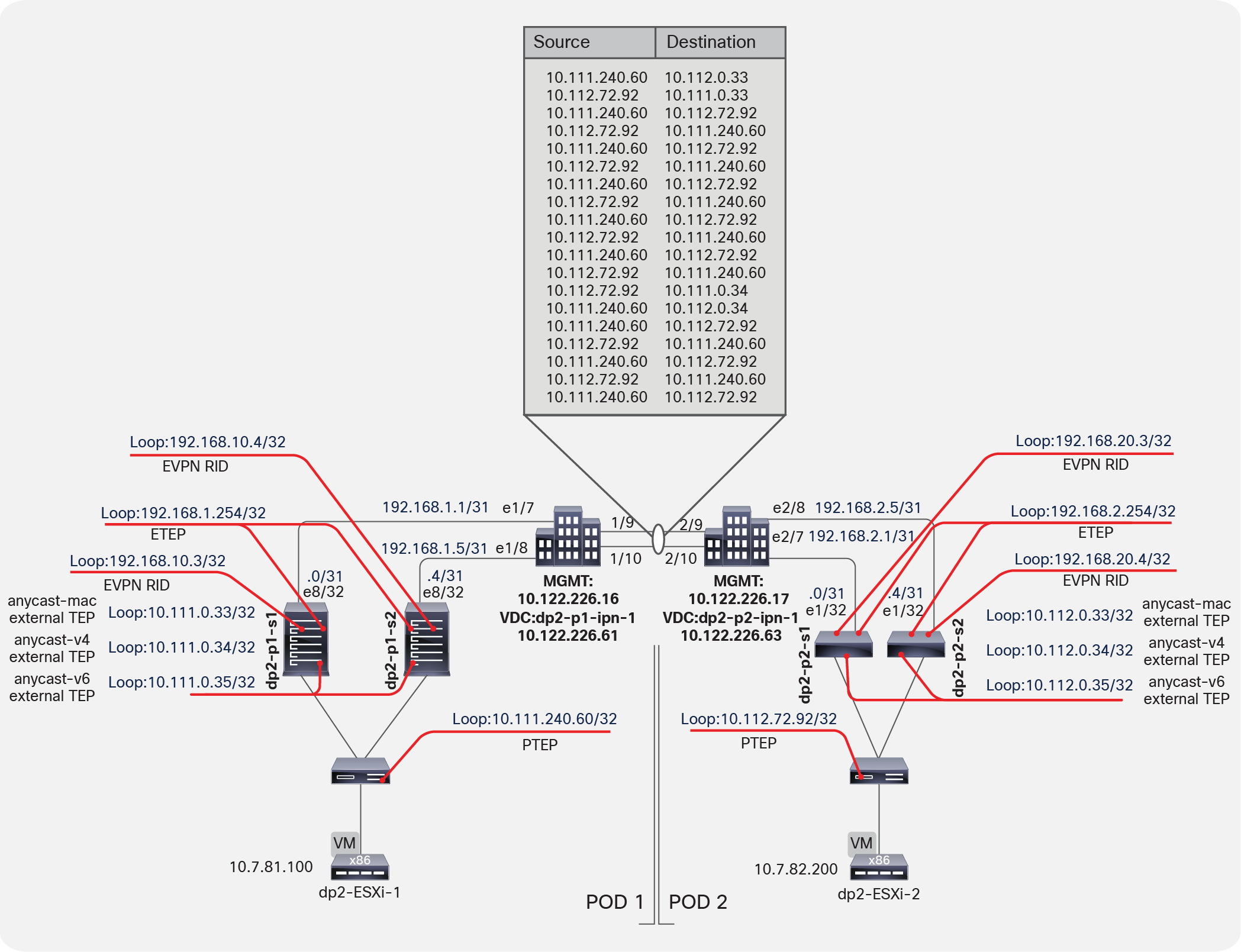
Packet Capture between IPN switches
You can decode the packet capture between the two IPN switches to examine the iVXLAN header, as shown in Figure 11.

Packet Capture to examine iVXLAN header
Dynamic tunnel: Different bridge domains and EPGs
The listing for leaf endpoints before any traffic communication is shown here.
dp2-p1-l1:
dp2-p1-l1# show endpoint
Legend:
O - peer-attached H - vtep a - locally-aged S - static
V - vpc-attached p - peer-aged L - local M - span
s - static-arp B - bounce
+-----------------------------------+---------------+-----------------+--------------+-------------+
VLAN/ Encap MAC Address MAC Info/ Interface
Domain VLAN IP Address IP Info
+-----------------------------------+---------------+-----------------+--------------+-------------+
17 vlan-10 0078.88f0.e79b O tunnel43
mgmt:inb vlan-10 10.7.80.11 O tunnel43
16 vlan-1068 0050.5688.af77 L eth1/1
mtarking-T1:mtarking-VRF vlan-1068 10.7.81.100 L eth1/1
overlay-1 10.111.240.60 L lo0
overlay-1 10.111.152.68 L lo1
dp2-p1-l1#
dp2-p2-l1:
dp2-p2-l1# show endpoint
Legend:
O - peer-attached H - vtep a - locally-aged S - static
V - vpc-attached p - peer-aged L - local M - span
s - static-arp B - bounce
+-----------------------------------+---------------+-----------------+--------------+-------------+
VLAN/ Encap MAC Address MAC Info/ Interface
Domain VLAN IP Address IP Info
+-----------------------------------+---------------+-----------------+--------------+-------------+
13 vlan-1067 0050.5688.d6a6 L eth1/1
mtarking-T1:mtarking-VRF vlan-1067 10.7.82.200 L eth1/1
15 vlan-1068 0050.5688.caa9 L eth1/1
mtarking-T1:mtarking-VRF vlan-1068 10.7.81.200 L eth1/1
overlay-1 10.112.72.92 L lo0
dp2-p2-l1#
The dynamic tunnel created has the virtual machine in Pod1 (10.7.81.100) send a ping to the virtual machine in Pod2 (10.7.82.200).
Note: Remember that these virtual machines are in different bridge domains and EPGs.
dp2-p1-l1:
dp2-p1-l1# show endpoint
Legend:
O - peer-attached H - vtep a - locally-aged S - static
V - vpc-attached p - peer-aged L - local M - span
s - static-arp B - bounce
+-----------------------------------+---------------+-----------------+--------------+-------------+
VLAN/ Encap MAC Address MAC Info/ Interface
Domain VLAN IP Address IP Info
+-----------------------------------+---------------+-----------------+--------------+-------------+
17 vlan-10 0078.88f0.e79b O tunnel43
mgmt:inb vlan-10 10.7.80.11 O tunnel43
mtarking-T1:mtarking-VRF 10.7.82.200 tunnel44
16 vlan-1068 0050.5688.af77 L eth1/1
mtarking-T1:mtarking-VRF vlan-1068 10.7.81.100 L eth1/1
overlay-1 10.111.240.60 L lo0
overlay-1 10.111.152.68 L lo1
dp2-p1-l1#
dp2-p2-l1:
dp2-p2-l1# show endpoint
Legend:
O - peer-attached H - vtep a - locally-aged S - static
V - vpc-attached p - peer-aged L - local M - span
s - static-arp B - bounce
+-----------------------------------+---------------+-----------------+--------------+-------------+
VLAN/ Encap MAC Address MAC Info/ Interface
Domain VLAN IP Address IP Info
+-----------------------------------+---------------+-----------------+--------------+-------------+
mtarking-T1:mtarking-VRF 10.7.81.100 tunnel21
13 vlan-1067 0050.5688.d6a6 L eth1/1
mtarking-T1:mtarking-VRF vlan-1067 10.7.82.200 L eth1/1
15 vlan-1068 0050.5688.caa9 L eth1/1
mtarking-T1:mtarking-VRF vlan-1068 10.7.81.200 L eth1/1
overlay-1 10.112.72.92 L lo0
dp2-p2-l1#
Figure 12 provides a visual representation of a packet capture performed between the IPN switches. You can see the use of the anycast ETEP addresses for the ping performed between the virtual machines and then the switchover to using the dynamically built tunnel directly between the VTEPs and leaf switches.
Anycast ETEP addresses
You can decode the packet capture between the two IPN switches to examine the iVXLAN header, as shown in Figure 13.
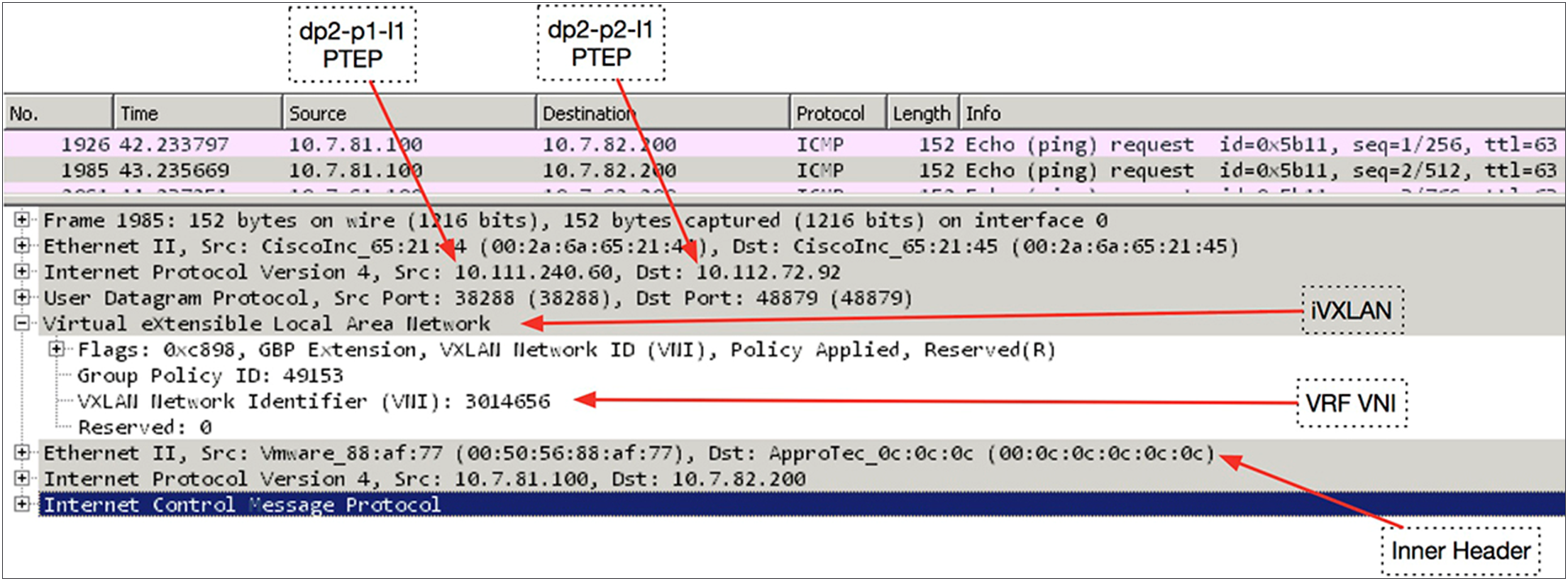
Decoding the packet capture between two IPN switches
Appendix: Configuring the Multi-Pod setup manually
Unlike Layer 3 connections in previous configurations, a Multi-Pod setup uses the spine switch ports. For this reason, new access policies are built that are attached to specific spine policies. These policies didn't exist previous to Cisco ACI Release 2.0. The first step is to build these policies in the Cisco ACI fabric to enable these spine ports.
Setting up Pod1
Your initial Pod1 will look like the normal fabric membership view, similar to the example shown below.
Defining Pod1 spine access policies
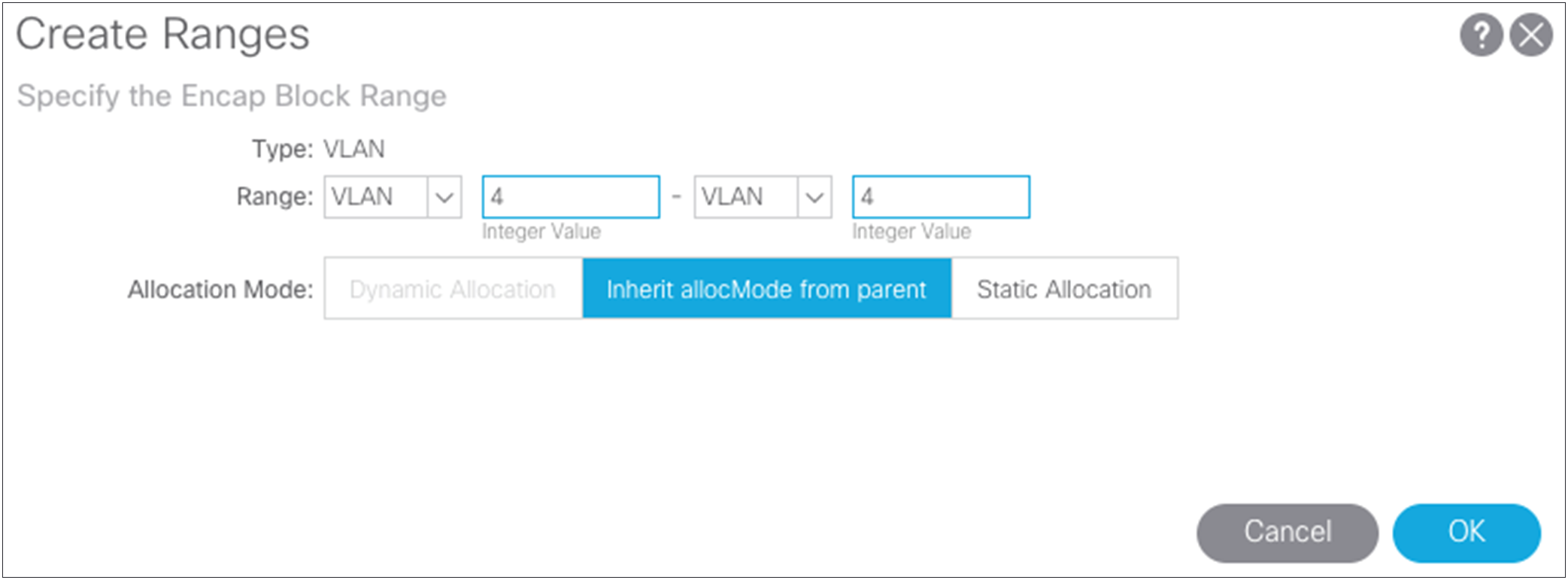
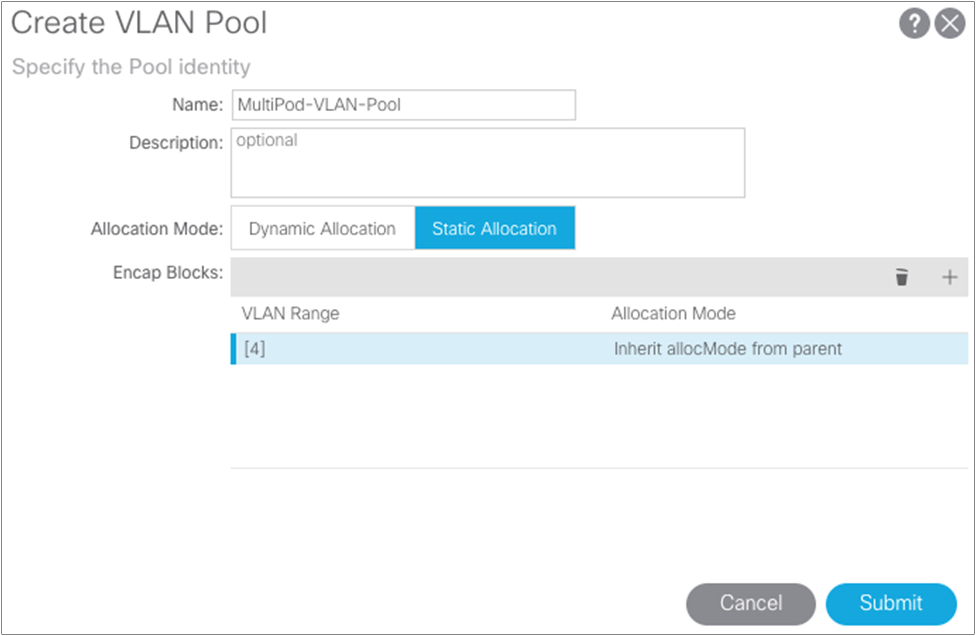
Just as for every port in the Cisco ACI fabric, you need to define access policies to define port behaviors. The policies for the spine ports are a little different from those defined in the past. The VLAN pool is specific to the spine switch and uses VLAN 4. This setting cannot be changed by the user. This policy will be attached to the Layer 3 domain.
Choose Fabric > Access Policies > Pools > VLANS and create a static VLAN pool that contains only VLAN 4.
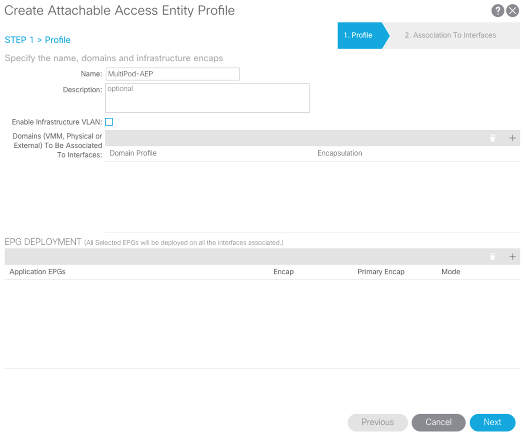
Next, you need to create the AEP. Choose Fabric > Access Policies > Global Policies > AEP.
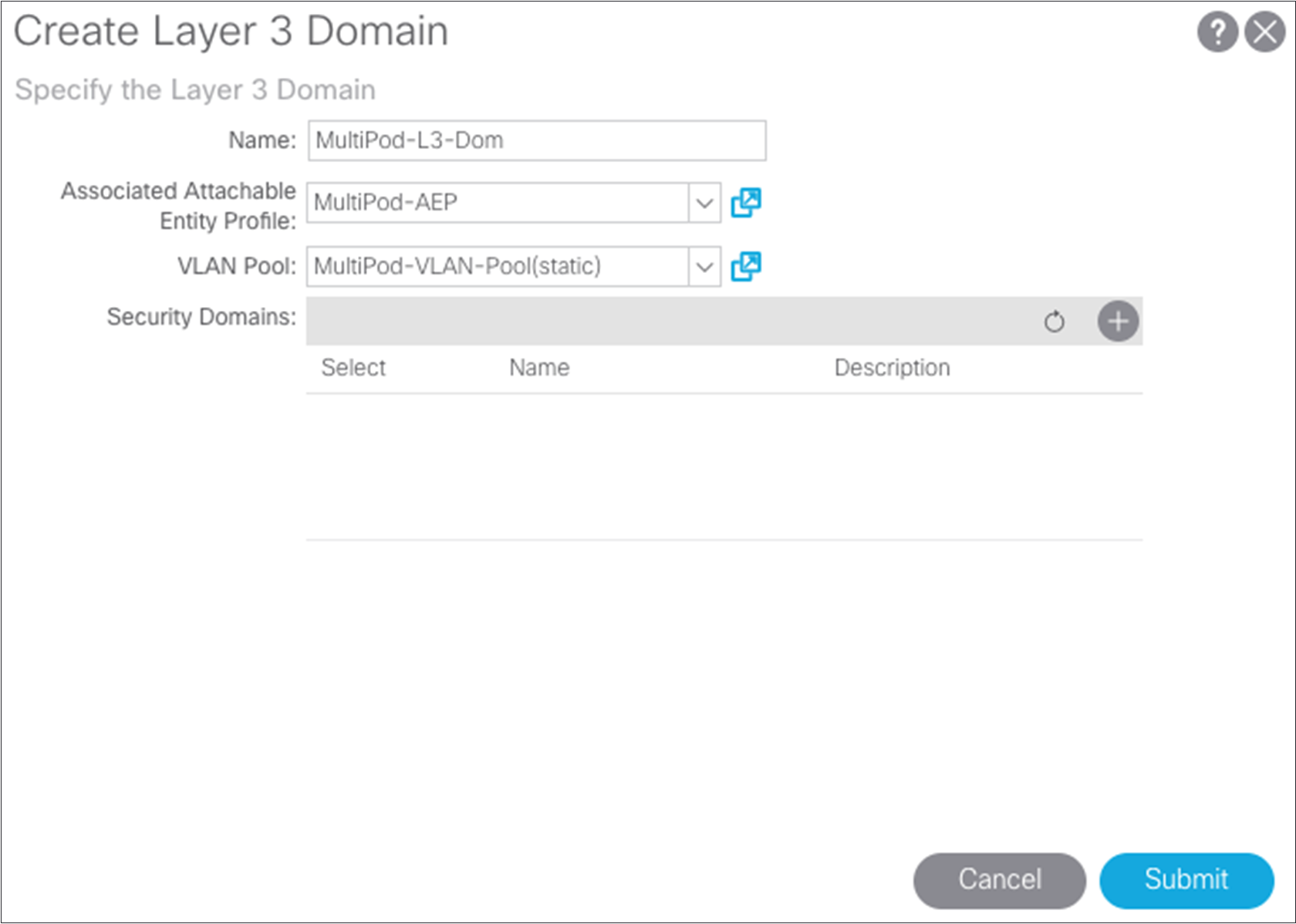
You can now build the Layer 3 domain that will associate the VLAN pool and AEP previously created and that will be associated with the interfaces of the spine switch.
Choose Fabric > Access Policies > Physical and External Domains > External Routed Domains.
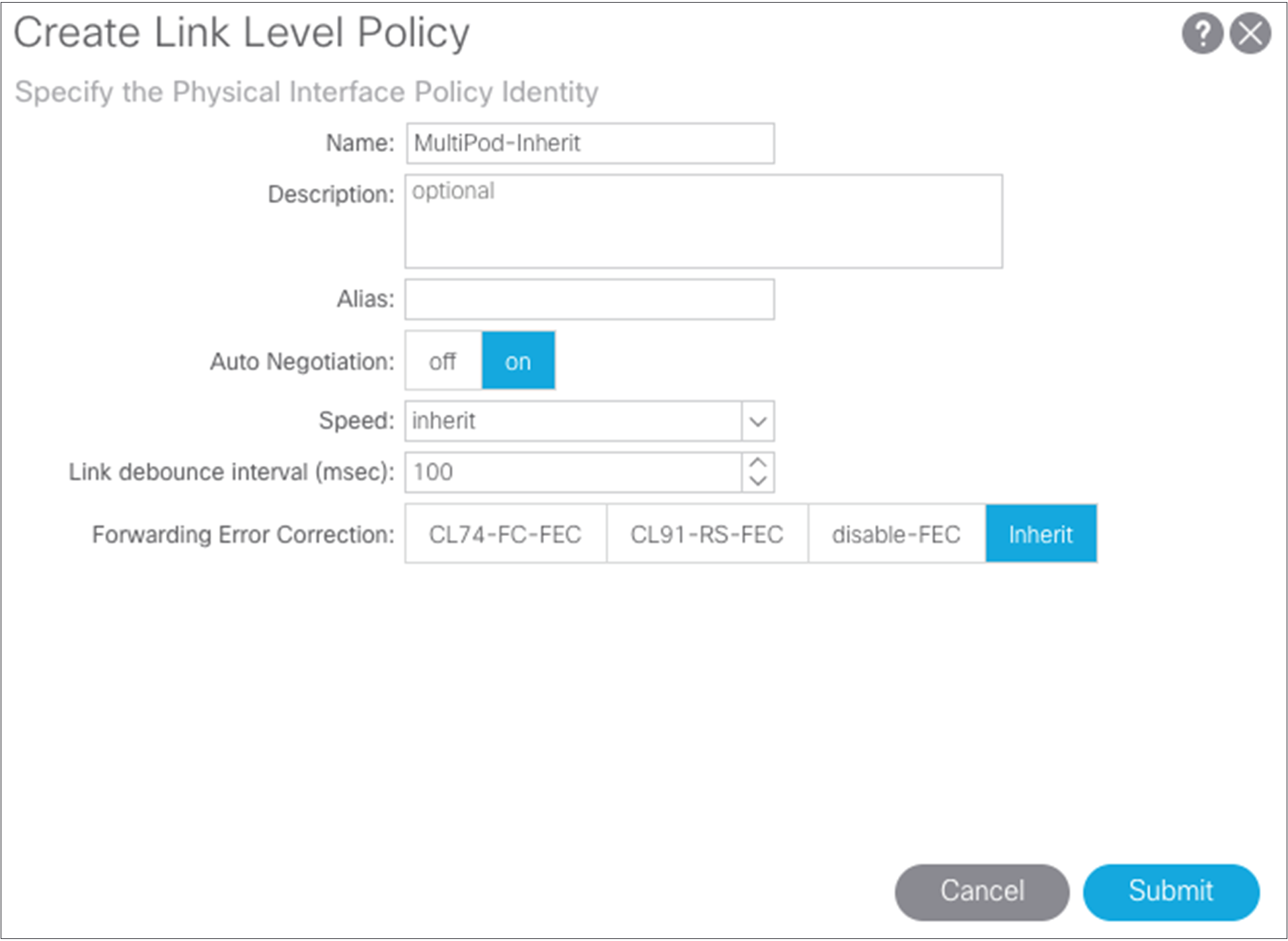
Starting with Cisco ACI Release 2.0, you can create the spine interface policies. To start, build a link-level interface policy. Choose Fabric > Access Policies > Interface Policies > Policies > Link Level. In the case here, use the configuration defaults.
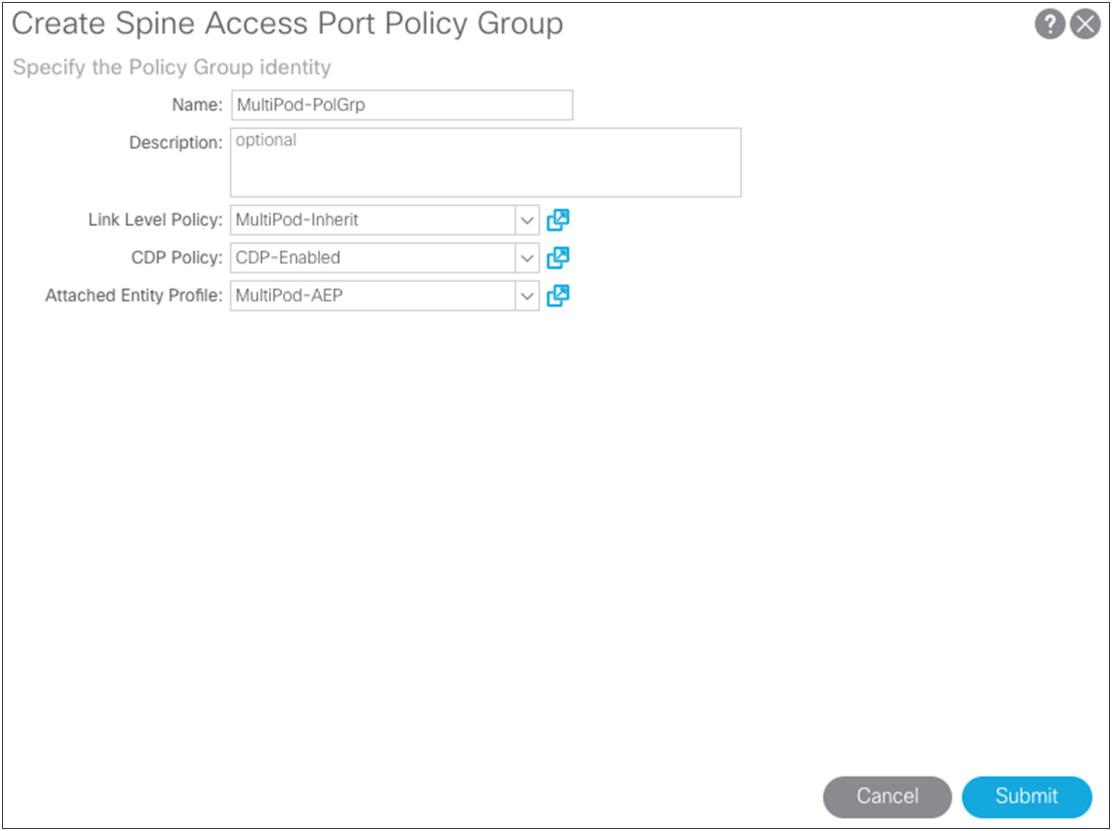
Next, create the spine policy group using the link-level policy and your previously created AEP. Choose Fabric > Access Policies > Interface Policies > Policy Group > Spine Policy Groups.
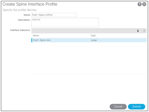
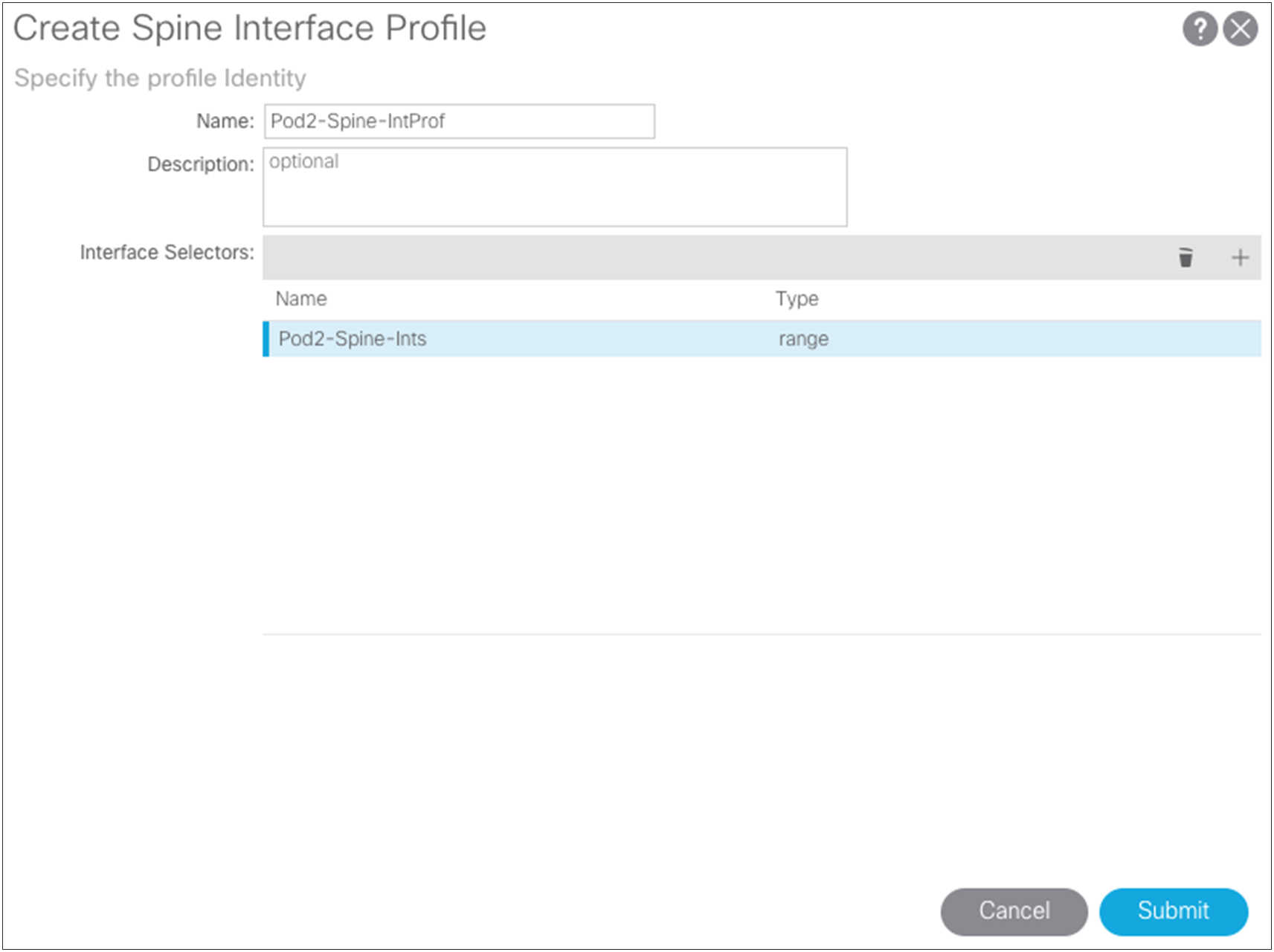
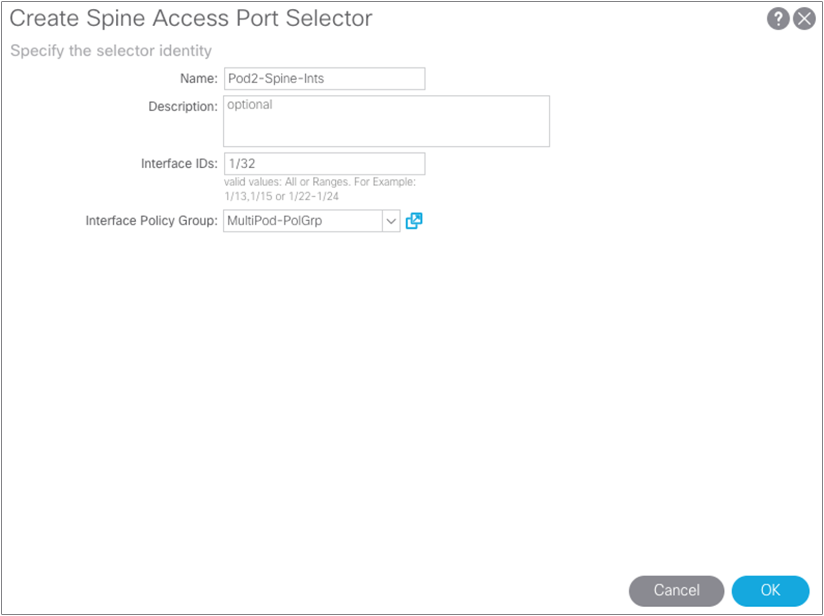
Next, create the spine interface profile definition. You can select multiple interfaces (a range) as needed. Choose Fabric > Access Policies > Interface Policies > Profiles > Spine Profiles. The setup here uses two 40-Gbps interfaces facing a Cisco Nexus 7000 Series Switch using ports 8/31 and 8/32.
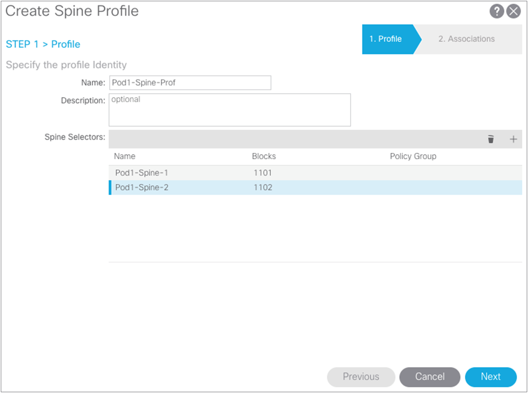
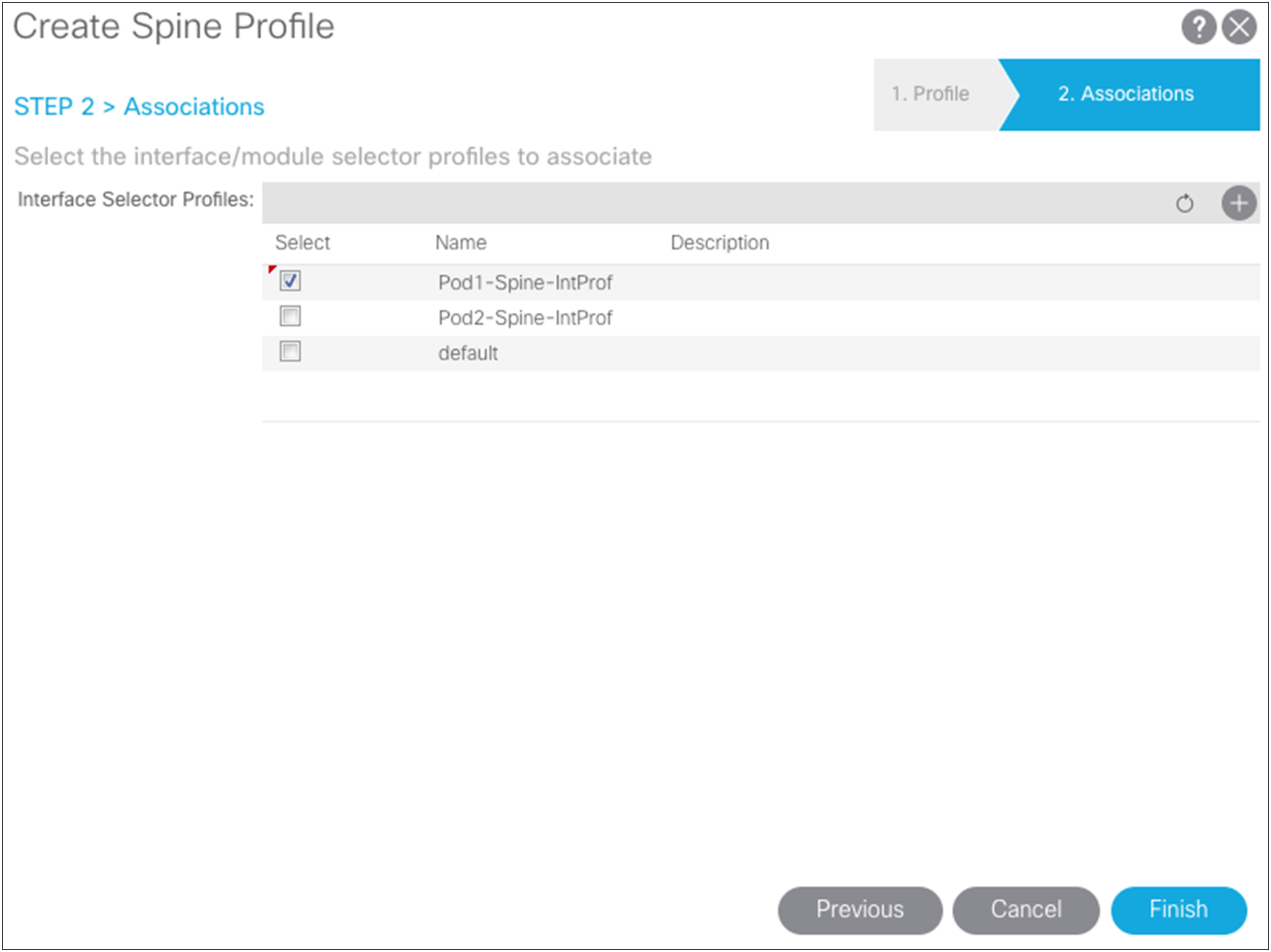
Now you can create the spine switch profile. Choose Fabric > Access Policies > Switch Policies > Profiles.
Defining Pod2 spine access policies
In Pod2, if you use different interfaces from the spine switches to the IPN, whether because you are using different line-card slots or different spine-switch models in Pod1 and Pod2 (for example, the Cisco Nexus 9508 Switch in one pod and the Cisco Nexus 9336PQ ACI Spine Switch in the other pod), you must create the same access policies for the spine switches that have yet to be discovered in the fabric. If your spine interfaces differ, you still can reuse the policy groups because the properties will be the same. If your spine interfaces are the same, you can simply add your spine nodes to the switch profile later, as explained in this document.
Setting up multiple pods
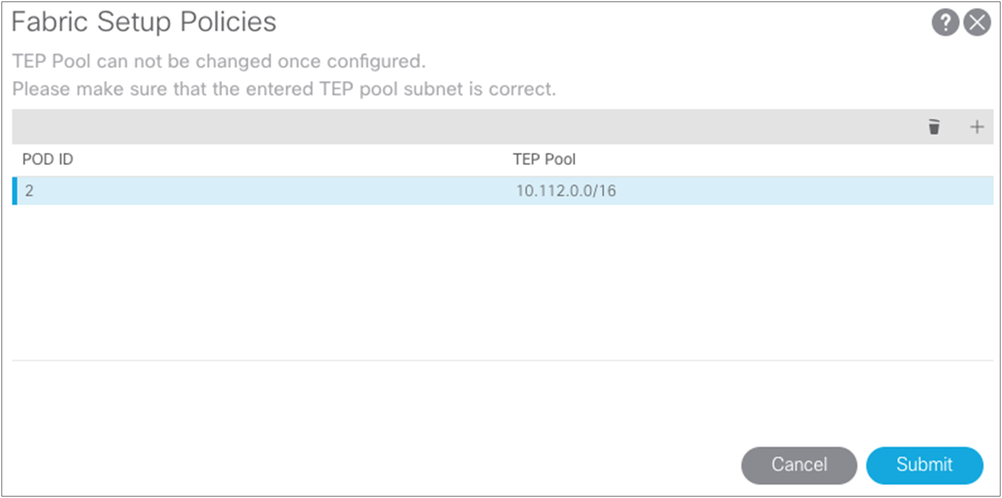
For this topology, you will create two pods. The original pool 10.111.0.0/16 was defined in the APIC startup configuration, but you need to define the TEP pool for the second pod. In this case, the two pools are:
● Pod1 - 10.111.0.0/16
● Pod2 - 10.112.0.0/16
In the setup here, each side has a /16 subnet to assign addresses for the TEP in the fabric. Choose Fabric > Inventory > POD Fabric Setup Utility > Setup PODs.
After both TEP pools have been defined, you can start the process of defining the Multi-Pod setup.
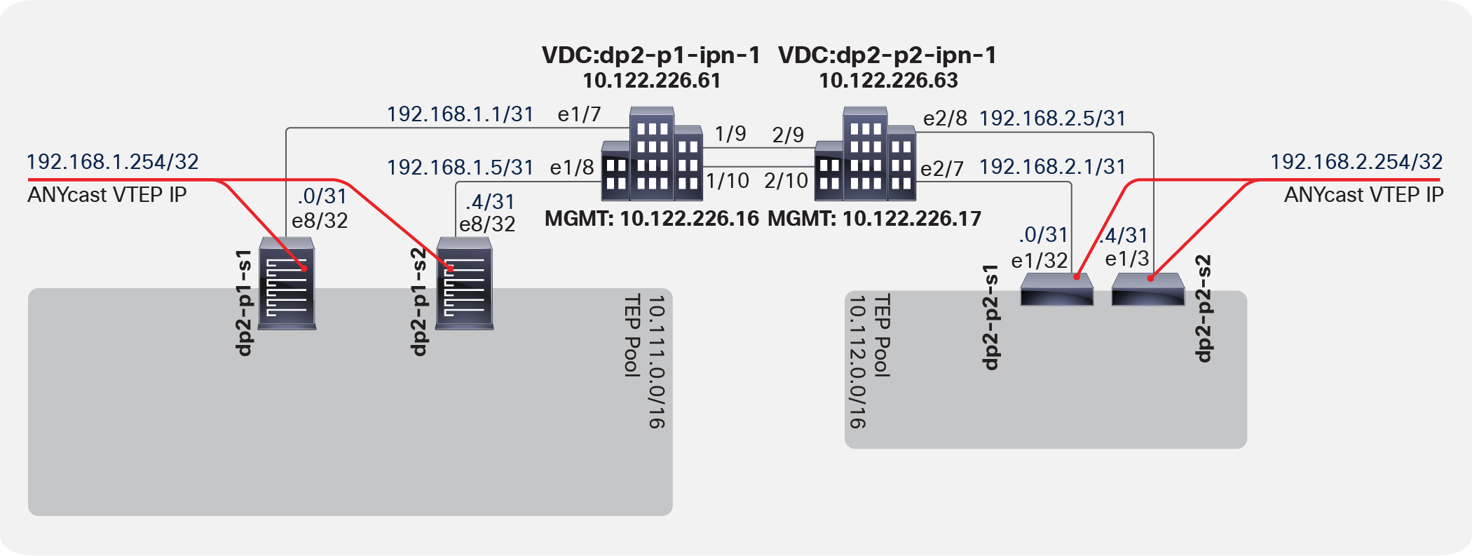
Two sides of the IPN with a unique network structure
Each of the two sides of the IPN has a unique network structure. For this topology, two separate /24 subnets, 192.168.1.0/24 and 192.168.2.0/24, are used across the connections between the IPN and the fabric spine switches. Choose Fabric > Inventory > POD Fabric Setup Policy > Create Multi-Pod.
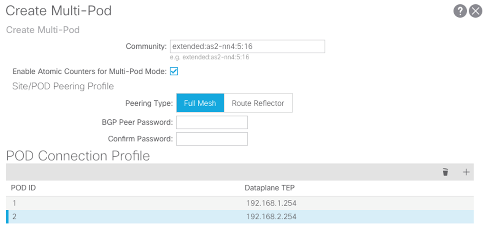
● In the Create Multi-Pod dialog box, you can copy the community string used in the example because any configured value will work for a Multi-Pod setup.
● Enable the atomic counters for the Multi-Pod setup so that atomic counters work from the leaf switches in one pod to those in the other pod.
● Choose Full Mesh or Route Reflector.
◦ Full Mesh works with a small set of spine switches interconnected with the IPN.
◦ Route Reflector provides a more robust mechanism for interconnecting a larger group of pods and spine switches. This document does not cover the configuration for the Route Reflector option.
For information on configuring route reflectors, see the "Route Distribution within the ACI Fabric" section about multiprotocol BGP (MP-BGP) MP-BGP in the following document: https://www.cisco.com/c/en/us/solutions/collateral/data-center-virtualization/application-centric-infrastructure/white-paper-c07-732033.html#_Toc395143552.
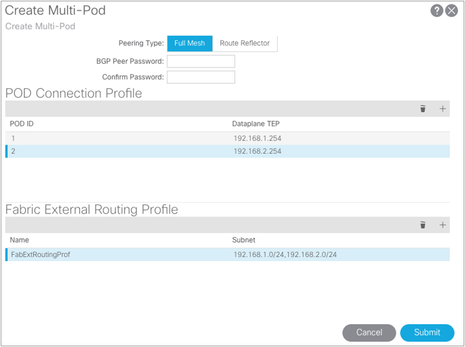
● The pod connection profile defines a new VXLAN TEP (VTEP) address called the external TEP (ETEP) address. It is used as the anycast shared address across all spine switches in a pod and as the EVPN next-hop IP address for interpod data-plane traffic. This IP address should not be part of the TEP pool assigned to each pod. You should use an IP address that is part of the external prefixes already used to address the point-to-point Layer 3 links between the spine switches and the IPN devices (192.168.1.0/24 and 192.168.2.0/24).
● The routing profile defines the subnets that are used in the point-to-point connections between the two separate pods in the IPN interfaces. The screenshots show the relationships and configuration values.
Configuring the routed-outside interface for EVPN
To define the routed-outside interface, you need to create some loopback connections from each of the spine switches. Figure 15 provides more details about these loopback connections.
Loopback functions
OSPF is currently the only routing protocol supported for this connection. Note that the loopback connections used here for the OSPF router ID will be used for Multiprotocol Interior BGP (MP-iBGP) EVPN peering between the spine switches in separate pods. This process is handled by the Cisco ACI fabric and is discussed later in this document.
To configure this connection for a Multi-Pod setup, choose Fabric > Inventory > POD Fabric Setup Policy > Create Routed Outside for Multi-Pod.
For this setup, use regular Area 0 for OSPF instead of using the Not-So-Stubby Area (NSSA). Then add the loopbacks you have defined and the interface definitions for the ports on the spine connections to the IPN switches. Using the wizard, also create your OSPF point-to-point protocol policy.
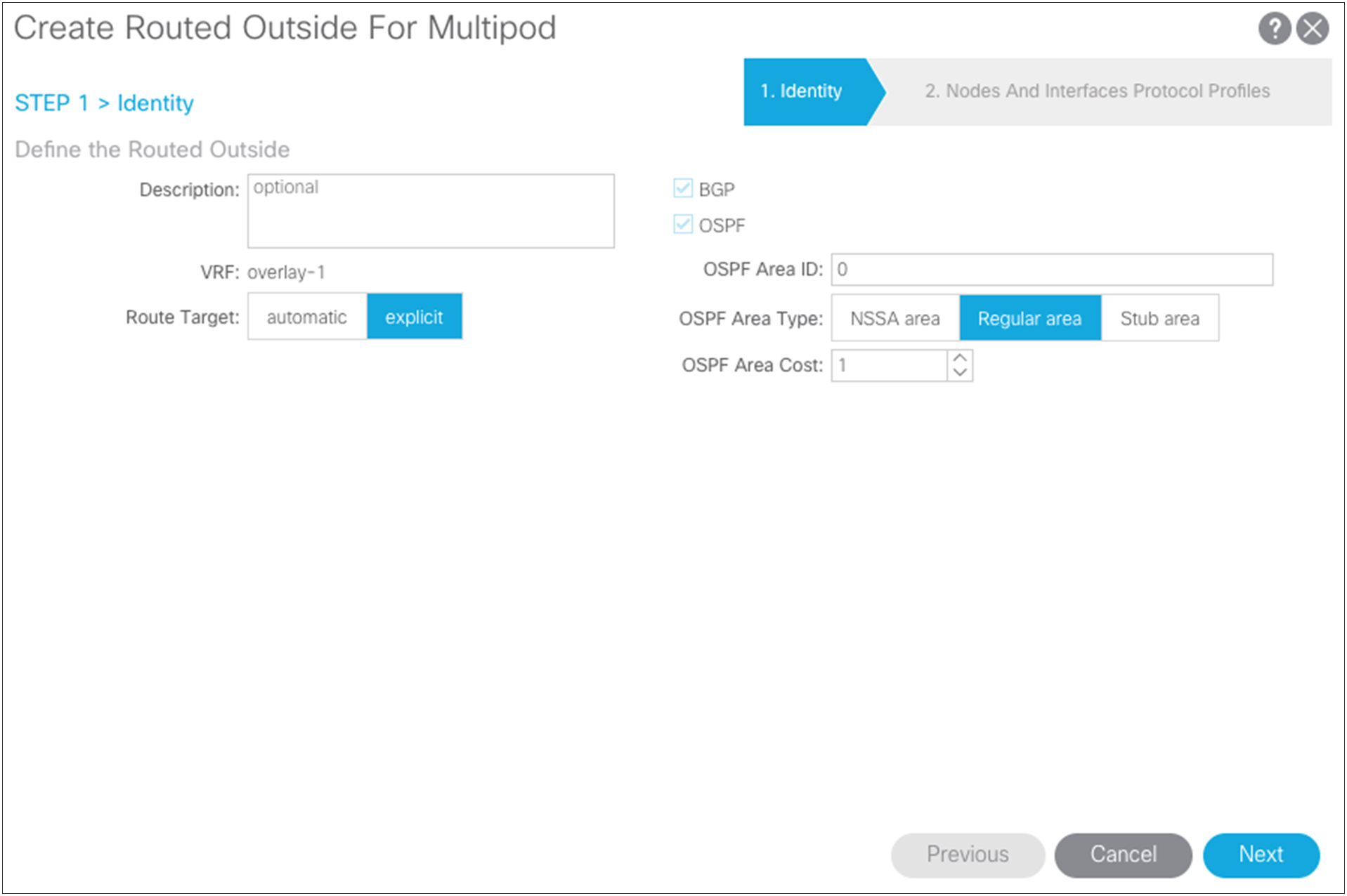
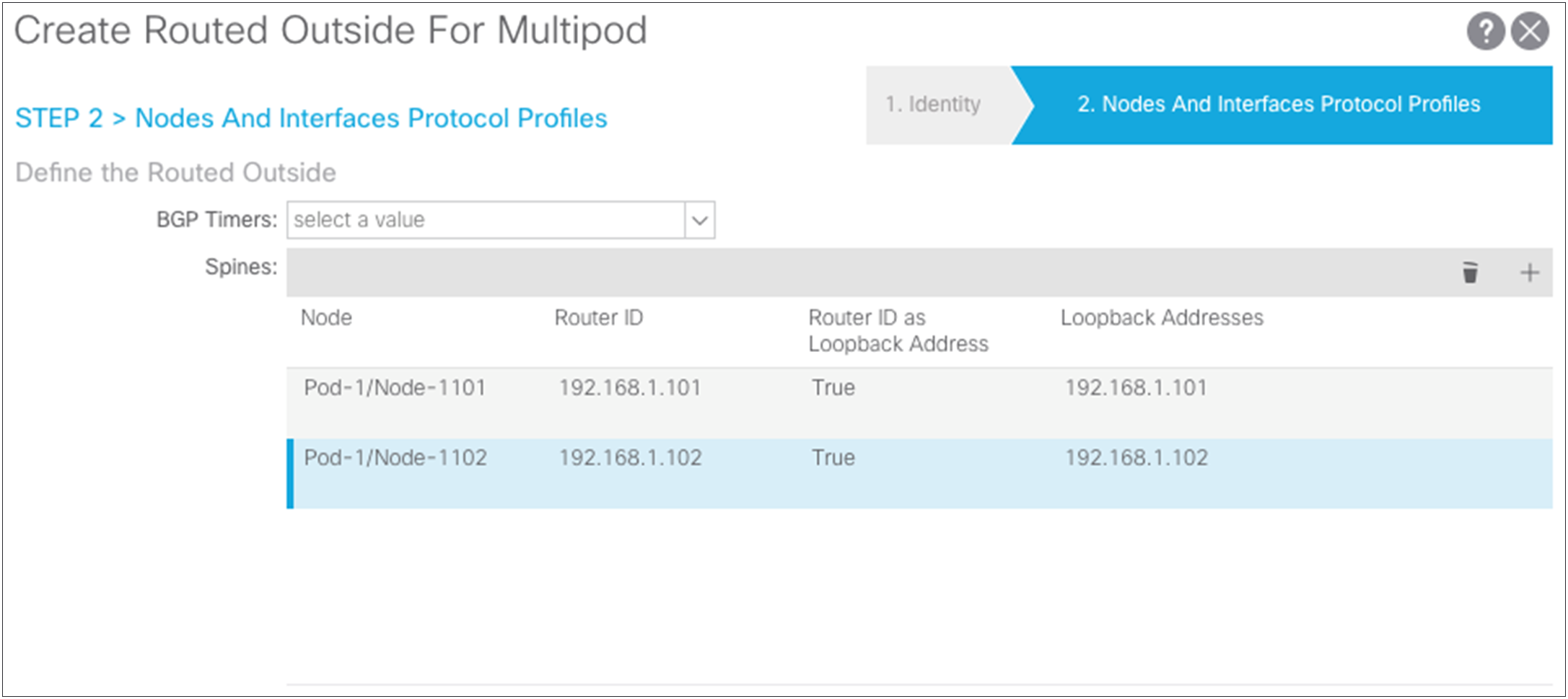
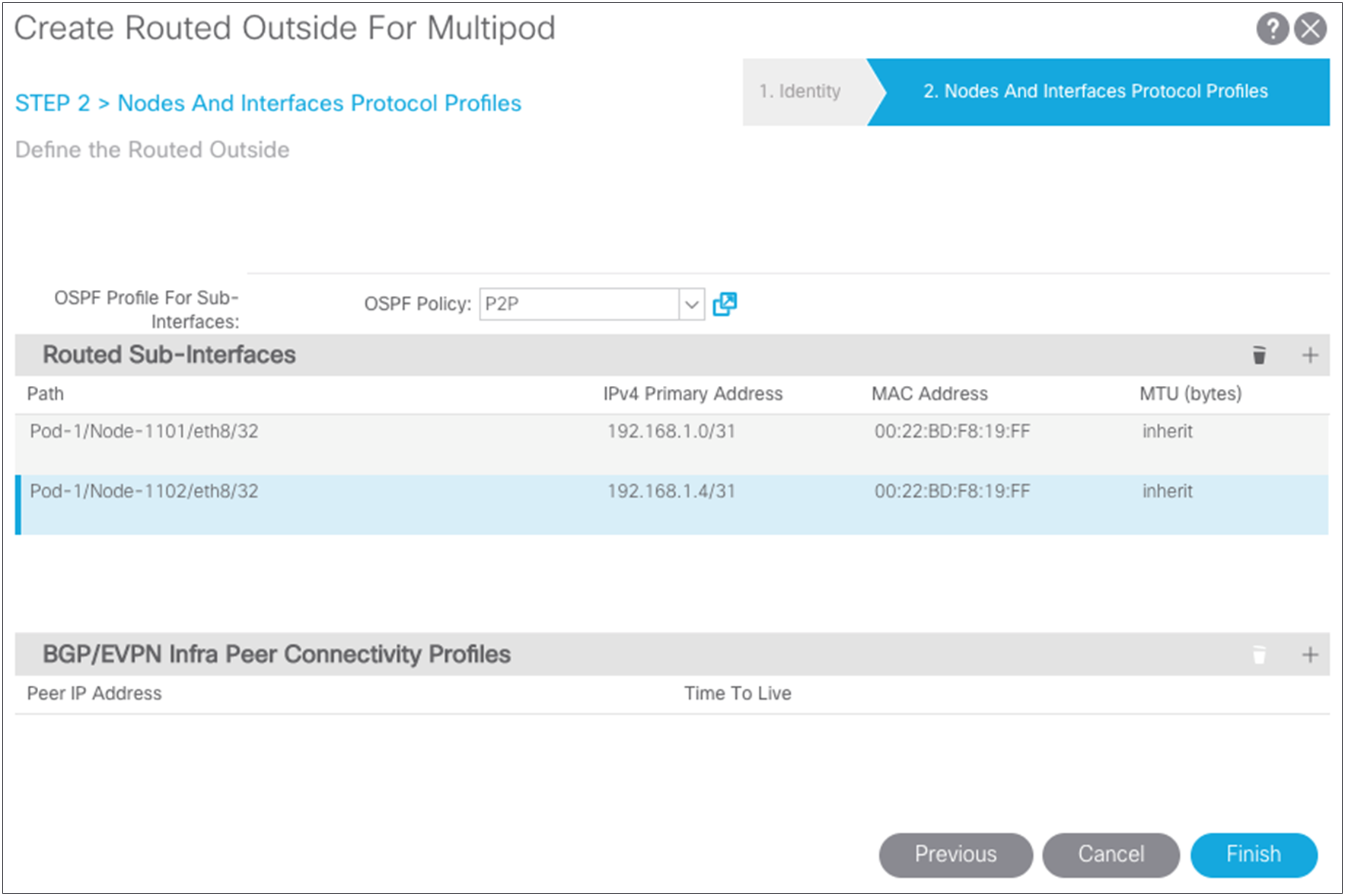
Pay attention to the Maximum Transmission Unit (MTU) value. Otherwise, you will need to configure OSPF to ignore the MTU. The best solution is to use 9150 as the MTU and set “inherit” to match the interface MTU. When these values match, the OSPF will be exchanged and match on both sides. You must set the MTU in the IPN interfaces to 9150 (to accommodate sizing for VXLAN across the IPN). For the rest of this document, the interface MTU is set in the IPN to 9150, and the profile is set to inherit on the Cisco ACI side. You cannot set the MTU for the OSPF policy to greater than 9000. If you do so, then you must select “MTU ignore” on the Cisco Nexus switch and change the protocol policy in Cisco ACI to ignore the MTU.
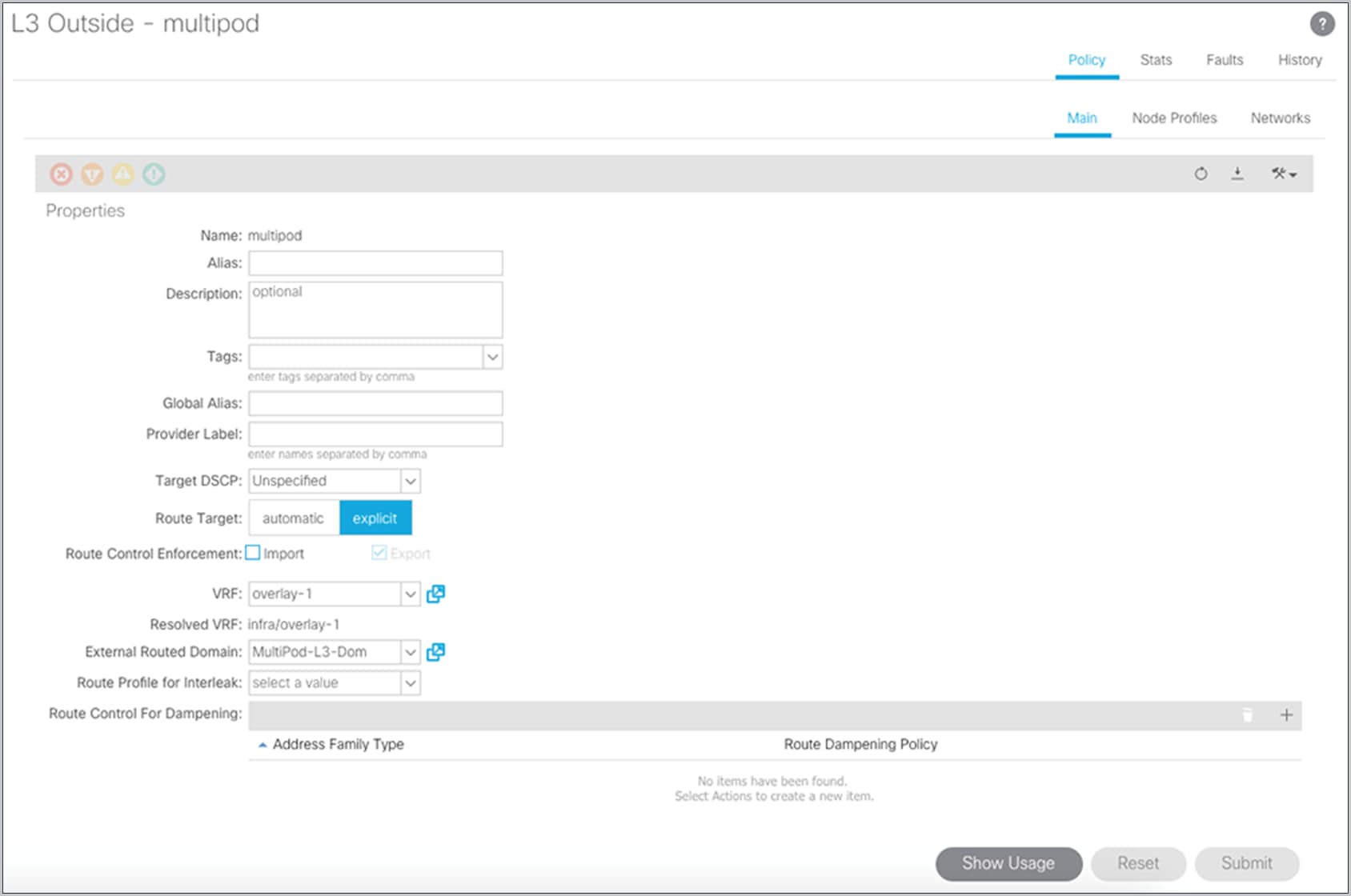
Updating the infrastructure interface: external routed
The next step is to associate the Multi-Pod domain with the external-routed infrastructure interface. Choose Tenants > Infra > Networking > External Routed Networks and select the L3Out interface named “Multi-Pod.”
Configuring fabric membership for Pod2 spine switches
After the OSPF adjacency has formed and the IPNs are performing proxy forwarding of the DHCP requests of the fabric, the two spine switches in Pod2 will appear in the Fabric Membership list. You can then configure the two spine switches and give them node IDs. At this point, the remote spine switches will not receive a TEP address until you revisit the Pod2 access policies and the IPN infrastructure L3Out interface.
Revisiting Pod2 spine access policies
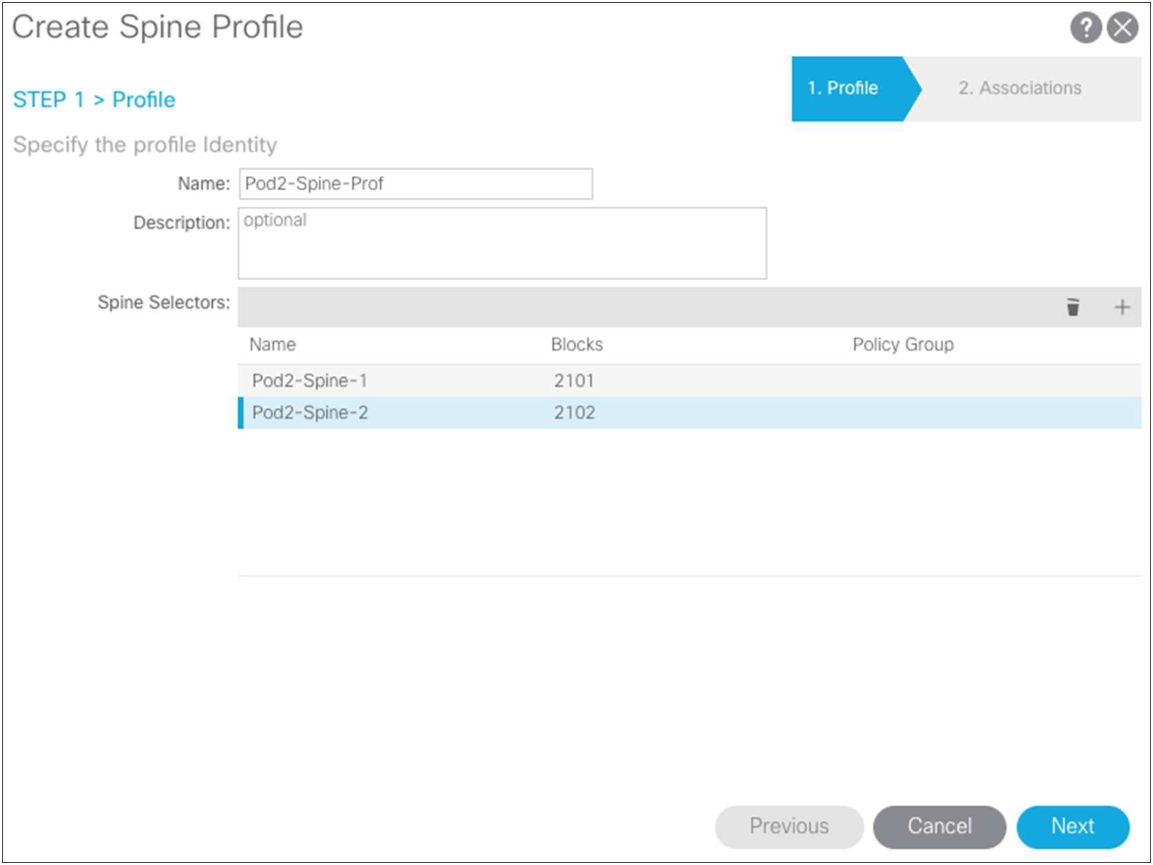
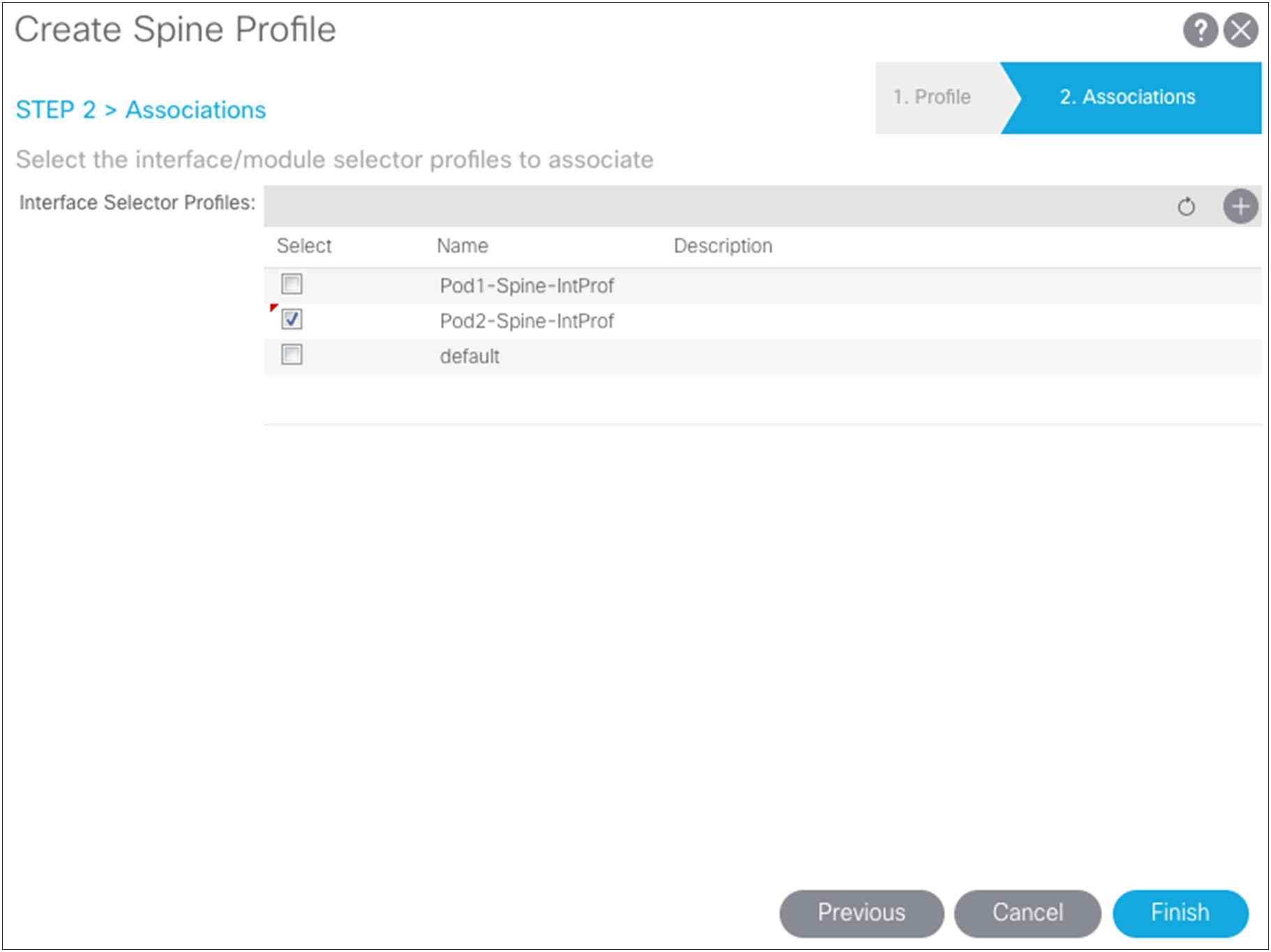
The remote Pod2 spine switches have been added to the fabric with node IDs, so now you can create access policies associated with them. Return to the access policies and create a spine profile for the Pod2 spine switches and associate the interface policy that you previously created. For the example in this document, separate spine policies are created because different ports are used on the spine switches in the different pods. If the spine ports are the same in both pods, you can use the same policies you created for Pod1.
Creating the routed-outside interface for Pod2
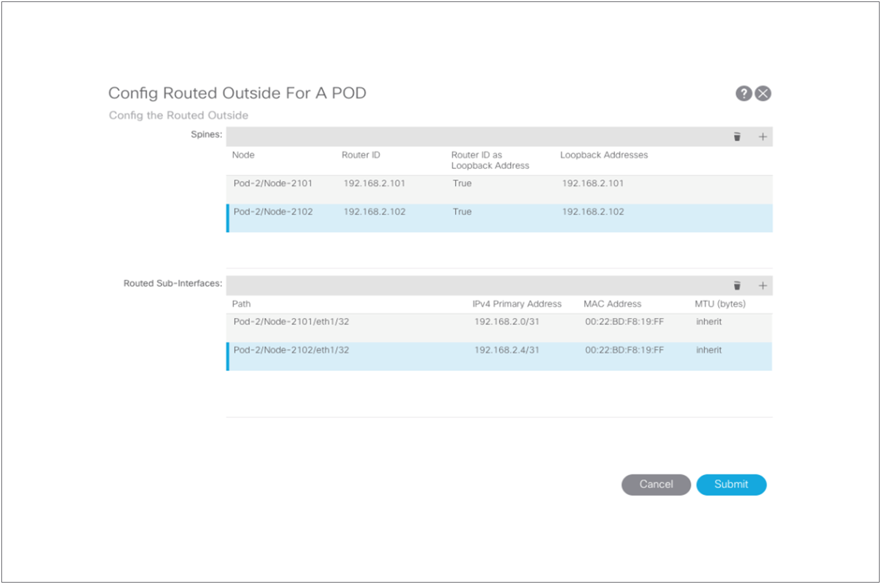
Now define the connection between the spine switches of Pod2 and the Cisco Nexus 7000 Series Switch. You are configuring the interface IP addresses that need to be matched with the IPN switch. Configure the Pod2 L3Out logical nodes and paths using the Config Pod wizard.
Choose “Topology.” Then click “Config Pod” in the pod dialog box to add the router ID and loopbacks for the remote spine switches peering to the IPN along with the peering paths and IP addresses used for peering to the IPN.