Cable and Connectors
Connector Specifications
10/100 Ports
The 10/100 Ethernet ports on the switches use RJ-45 connectors. Figure 48 shows the pinouts.
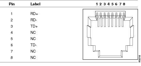
For the three models of IE 2000 switch that support PoE, connector pins 3 and 6 supply +48/+54 VDC and pins 1 and 2 are the DC voltage return lines.
SFP Module Connectors
Figure 49 shows the MT-RJ SFP module fiber-optic local connector (LC).
Figure 49 Fiber-Optic SFP Module LC Connector
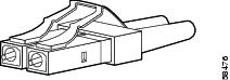
Warning: Invisible laser radiation may be emitted from disconnected fibers or connectors. Do not stare into beams or view directly with optical instruments.![]() Statement 1051
Statement 1051
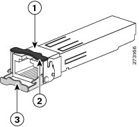
Figure 50 shows the 1000BASE-T SFP module RJ-45 connector.
Figure 50 1000BASE-T SFP Module Connector
|
|
|
Bale-clasp latching mechanism in the open (unlocked) position |
|
|
|
Bale-clasp latching mechanism in the closed (locked) position |
Dual-Purpose Ports
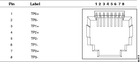
The 10/100/1000 Ethernet ports on the dual-purpose ports use RJ-45 connectors. Figure 51 shows the pinouts.
Figure 51 10/100/1000 Port Pinouts
Console Port
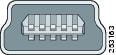
The switch has two console ports: a USB 5-pin mini-Type B port on the front panel (see Figure 52) and an RJ-45 console port on the rear panel.
Figure 52 USB Mini-Type B Port
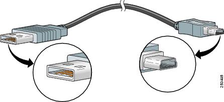
The USB console port uses a USB Type A to 5-pin mini-Type B cable, shown in Figure 53. The USB Type A-to-USB mini-Type B cable is not supplied. You can order an accessory kit (part number 800-33434) that contains this cable.
Figure 53 USB Type A-to-USB 5-Pin Mini-Type B Cable
The RJ-45 console port uses an 8-pin RJ-45 connector (see Table 22 and Table 23). The supplied RJ-45-to-DB-9 adapter cable is used to connect the console port of the switch to a console PC. You need to provide an RJ-45-to-DB-25 female DTE adapter if you want to connect the switch console port to a terminal. You can order a kit (part number ACS-DSBUASYN=) containing that adapter. For console port and adapter pinout information, see Table 22 and Table 23.
Alarm Port
For information on alarm ratings, see Alarm Ratings.
The labels for the alarm connector pin-outs are on the switch panel and are displayed in Table 18.
|
|
|
|---|---|
Cables and Adapters
SFP Module Cables
Each port must match the wave-length specifications on each end of the cable, and for reliable communications, the cable must not exceed the allowable length. Copper 1000BASE-T SFP transceivers use standard four twisted-pair, CAT5 (or greater) cable at lengths up to 328 feet (100 meters).
■![]() The maximum operating temperature of the switch varies depending on SFP module type. See Table 2 for supported temperature ranges.
The maximum operating temperature of the switch varies depending on SFP module type. See Table 2 for supported temperature ranges.
■![]() Modal bandwidth applies only to multimode fiber (MMF).
Modal bandwidth applies only to multimode fiber (MMF).
■![]() A mode-field diameter/cladding diameter = 9 micrometers/125 micrometers.
A mode-field diameter/cladding diameter = 9 micrometers/125 micrometers.
■![]() 1000BASE-LX/LH SFP modules connected with MMF over a short link distance require a mode-conditioning patch cord.
1000BASE-LX/LH SFP modules connected with MMF over a short link distance require a mode-conditioning patch cord.
Ordinary patch cords can cause transceiver saturation, resulting in an elevated bit error rate (BER). Using the 1000BASE-LX/LH SFP module with 62.5-micron diameter multimode fiber (MMF) requires a mode-conditioning patch cord between the single mode fiber (SMF) SFP module and the MMF cable on both the send and receive link ends.
■![]() Link distances greater than 984 feet (300 m) require a mode-conditioning patch cord.
Link distances greater than 984 feet (300 m) require a mode-conditioning patch cord.
■![]() 1000BASE-ZX SFP modules can send data up to 62 miles (100 km) by using dispersion-shifted SMF or low-attenuation SMF. The distance depends on fiber quality, the number of splices, and the connectors.
1000BASE-ZX SFP modules can send data up to 62 miles (100 km) by using dispersion-shifted SMF or low-attenuation SMF. The distance depends on fiber quality, the number of splices, and the connectors.
■![]() Fiber-optic cable spans less than 15.43 miles (25 km) require a 5-decibel (dB) or 10-dB inline optical attenuator between the fiber-optic cable plant and the receiving port on the 1000BASE-ZX SFP module.
Fiber-optic cable spans less than 15.43 miles (25 km) require a 5-decibel (dB) or 10-dB inline optical attenuator between the fiber-optic cable plant and the receiving port on the 1000BASE-ZX SFP module.
View the CWDM data sheet at http://www.cisco.com/en/US/prod/collateral/modules/ps5455/ps6575/product_data_sheet09186a00801a557c_ps4999_Products_Data_Sheet.html
View the DWDM data sheet at http://www.cisco.com/en/US/prod/collateral/modules/ps5455/ps6576/product_data_sheet0900aecd80582763.html
Cable Pinouts
Figure 54 Two Twisted-Pair Straight-Through Cable Schematic for 10/100 Ports
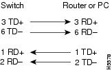
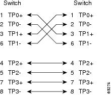
Figure 55 Two Twisted-Pair Crossover Cable Schematic for 10/100 Ports
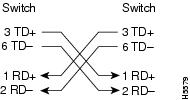
Figure 56 Four Twisted-Pair Straight-Through Cable Schematic for 1000BASE-T Ports
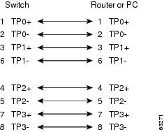
Figure 57 Four Twisted-Pair Crossover Cable Schematics for 1000BASE-T Ports
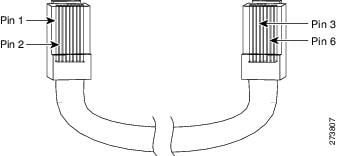
To identify a crossover cable, hold the cable ends side-by-side, with the tab at the back. The wire connected to pin 1 on the left end should be the same color as the wire connected to pin 3 on the right end. The wire connected to pin 2 on the left end should be the same color as the wire connected to pin 6 on the right end.
Figure 58 Identifying a Crossover Cable
Console Port Adapter Pinouts
The console port uses an 8-pin RJ-45 connector, which is described in b and Table 23. If you did not order a console cable, you need to provide an RJ-45-to-DB-9 adapter cable to connect the switch console port to a PC console port. You need to provide an RJ-45-to-DB-25 female DTE adapter if you want to connect the switch console port to a terminal. You can order an adapter (part number ACS-DSBUASYN=). For console port and adapter pinout information, see Table 22 and Table 23.
Table 22 lists the pinouts for the console port, the RJ-45-to-DB-9 adapter cable, and the console device.
|
|
|
Device |
|---|---|---|
|
|
|
|
Table 23 lists the pinouts for the switch console port, RJ-45-to-DB-25 female DTE adapter, and the console device.
Note: The RJ-45-to-DB-25 female DTE adapter is not supplied with the switch. You can order this adapter from Cisco (part number ACS-DSBUASYN=).
|
|
|
|
|---|---|---|
|
|
|
|
 Feedback