Running Express Setup
When you first set up the switch, you should use Express Setup to enter the initial IP information. This process enables the switch to connect to local routers and the Internet. You can then access the switch through the IP address for additional configuration.
You need this equipment to set up the switch:
■![]() PC with Windows XP, Vista, or Windows 7
PC with Windows XP, Vista, or Windows 7
■![]() Web browser (Internet Explorer 6.0, 7.0 or Firefox 1.5, 2.0, 3.0 or later) with JavaScript enabled
Web browser (Internet Explorer 6.0, 7.0 or Firefox 1.5, 2.0, 3.0 or later) with JavaScript enabled
■![]() Straight-through or crossover Category 5 or higher grade cable
Straight-through or crossover Category 5 or higher grade cable
Before running Express Setup, disable any pop-up blockers or proxy settings on your browser and any wireless client running on your PC.
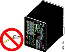
1.![]() Make sure that nothing is connected to the switch.
Make sure that nothing is connected to the switch.
During Express Setup, the switch acts as a DHCP server. If your PC has a static IP address, temporarily configure your PC settings to use DHCP before going to the next step.
Note: Write down the static IP address. You will need this IP address in Step 13.
2.![]() Connect power to the switch.
Connect power to the switch.
See the wiring instructions in Grounding the Switch and Wiring the DC Power Source.
3.![]() After the switch powers on, it begins the boot fast sequence, which can take up to 60 seconds.
After the switch powers on, it begins the boot fast sequence, which can take up to 60 seconds.
During boot fast, the SYS LED blinks green, and the other LEDs turn green.
When boot fast is complete, the SYS LED turns green, and the other LEDs turn off.
If the SYS LED is off (system not powered on), continues to blink green (POST in progress), or is solid red (Fault), contact the Cisco Technical Assistance Center (TAC). The SYS LED should be solid green when operating normally in Cisco IOS.
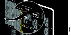
4.![]() Press the Express Setup button for 2 to 3 seconds. This button is recessed behind the front panel, so you can use a simple tool, such as a paper clip.
Press the Express Setup button for 2 to 3 seconds. This button is recessed behind the front panel, so you can use a simple tool, such as a paper clip.
When you press the Express Setup button, a switch port LED begins blinking green.
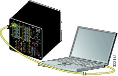
5.![]() Connect a Category 5 Ethernet cable (not provided) from the blinking switch port to the Ethernet port on your PC.
Connect a Category 5 Ethernet cable (not provided) from the blinking switch port to the Ethernet port on your PC.
The port LEDs on your PC and on the switch blink green while the switch configures the connection. The green port LEDs indicate a successful connection.
If the port LEDs do not turn green after about 30 seconds, make sure that:
–![]() You connected the Ethernet cable to one of the downlink switch ports (not to an uplink port such as the dual-purpose port).
You connected the Ethernet cable to one of the downlink switch ports (not to an uplink port such as the dual-purpose port).
–![]() You are using an undamaged Category 5 or higher grade cable.
You are using an undamaged Category 5 or higher grade cable.
–![]() The other device is turned on.
The other device is turned on.
6.![]() When the Setup LED turns solid green, start a browser session on the PC. A login prompt appears.
When the Setup LED turns solid green, start a browser session on the PC. A login prompt appears.
7.![]() Leave the username blank and enter the default password, cisco.
Leave the username blank and enter the default password, cisco.
Note: The switch ignores text in the username field.
The Express Setup window appears.
If the Express Setup window does not appear, make sure that any pop-up blockers or proxy settings on your browser are disabled and that any wireless client is disabled on your PC or laptop.
8.![]() Enter all entries in English letters and Arabic numbers.
Enter all entries in English letters and Arabic numbers.
In the Network Settings fields:
–![]() Management Interface (VLAN) : We recommend using the default, VLAN 1. The management VLAN establishes an IP connection to the switch.
Management Interface (VLAN) : We recommend using the default, VLAN 1. The management VLAN establishes an IP connection to the switch.
Note: Enter a new VLAN ID only if you want to change the management interface through which you manage the switch. The VLAN ID range is 1 to 1001.
–![]() IP Assignment Mode : We recommend using the default, Static, so that the switch always has the IP address that you assign. Use the DHCP setting when you want the switch to automatically obtain an IP address from a DHCP server.
IP Assignment Mode : We recommend using the default, Static, so that the switch always has the IP address that you assign. Use the DHCP setting when you want the switch to automatically obtain an IP address from a DHCP server.
–![]() IP Address : Enter the IP address for the switch. You can later use the IP address to access the switch through Device Manager.
IP Address : Enter the IP address for the switch. You can later use the IP address to access the switch through Device Manager.
–![]() Subnet Mask : Select a mask from the drop-down list.
Subnet Mask : Select a mask from the drop-down list.
–![]() Default Gateway : Enter the IP address of the router.
Default Gateway : Enter the IP address of the router.
–![]() Switch Password : Enter a password. The password can be from 1 to 25 alphanumeric characters, can start with a number, is case sensitive, allows embedded spaces, but does not allow spaces at the beginning or end. In the Confirm Password field, enter the password again.
Switch Password : Enter a password. The password can be from 1 to 25 alphanumeric characters, can start with a number, is case sensitive, allows embedded spaces, but does not allow spaces at the beginning or end. In the Confirm Password field, enter the password again.
Note: You must change the password from the default password, cisco.
9.![]() Enter the Control Industrial Protocol (CIP) VLAN settings:
Enter the Control Industrial Protocol (CIP) VLAN settings:
–![]() CIP VLAN: Enter the VLAN on which CIP will be enabled. The CIP VLAN can be the same as the management VLAN, or you can isolate CIP traffic on another VLAN that is already configured on the switch. The default CIP VLAN is VLAN 1. Only one VLAN on a switch can have CIP enabled.
CIP VLAN: Enter the VLAN on which CIP will be enabled. The CIP VLAN can be the same as the management VLAN, or you can isolate CIP traffic on another VLAN that is already configured on the switch. The default CIP VLAN is VLAN 1. Only one VLAN on a switch can have CIP enabled.
–![]() IP Address: Enter the IP address for the CIP VLAN. If the CIP VLAN is different from the management VLAN, you must specify an IP address for the CIP VLAN. Make sure that the IP address that you assign to the switch is not being used by another device in your network.
IP Address: Enter the IP address for the CIP VLAN. If the CIP VLAN is different from the management VLAN, you must specify an IP address for the CIP VLAN. Make sure that the IP address that you assign to the switch is not being used by another device in your network.
–![]() Subnet Mask: Select a mask from the drop-down list.
Subnet Mask: Select a mask from the drop-down list.
For more information about the CIP VLAN settings, click Help on the toolbar.
You can enter the optional information now, or enter it later by using Device Manager. For more information about the Express Setup fields, see the online help for the Express Setup window.
Click Submit to save your changes and to complete the initial setup.
For more information about the optional settings, click Help on the toolbar.
11.![]() After you click Submit, these events occur:
After you click Submit, these events occur:
–![]() The switch is configured and exits Express Setup mode.
The switch is configured and exits Express Setup mode.
–![]() The browser displays a warning message and tries to connect with the earlier switch IP address. Typically, connectivity between the PC and the switch is lost because the configured switch IP address is in a different subnet from the IP address on the PC.
The browser displays a warning message and tries to connect with the earlier switch IP address. Typically, connectivity between the PC and the switch is lost because the configured switch IP address is in a different subnet from the IP address on the PC.
12.![]() Turn off DC power at the source, disconnect all cables to the switch, and install the switch in your network. See Management Options for information about configuring and managing the switch.
Turn off DC power at the source, disconnect all cables to the switch, and install the switch in your network. See Management Options for information about configuring and managing the switch.
13.![]() If you changed the static IP address on your PC in Step 1, change it to the previously configured static IP address.
If you changed the static IP address on your PC in Step 1, change it to the previously configured static IP address.
14.![]() You can now manage the switch by using the Cisco Network Assistant, Device Manager, or the Cisco IOS Command Line Interface (CLI). See Management Options for information about configuring and managing the switch.
You can now manage the switch by using the Cisco Network Assistant, Device Manager, or the Cisco IOS Command Line Interface (CLI). See Management Options for information about configuring and managing the switch.
You can display Device Manager by following these steps:
a.![]() Start a web browser on your PC or laptop.
Start a web browser on your PC or laptop.
b.![]() Enter the switch IP address, username, and password (assigned in Step 7) in the web browser, and press Enter. The Device Manager page appears.
Enter the switch IP address, username, and password (assigned in Step 7) in the web browser, and press Enter. The Device Manager page appears.
If the Device Manager page does not appear:
■![]() Confirm that the port LED for the switch port connected to your network is green.
Confirm that the port LED for the switch port connected to your network is green.
■![]() Confirm that the PC or laptop that you are using to access the switch has network connectivity by connecting it to a well-known web server in your network. If there is no network connection, troubleshoot the network settings on the PC or laptop.
Confirm that the PC or laptop that you are using to access the switch has network connectivity by connecting it to a well-known web server in your network. If there is no network connection, troubleshoot the network settings on the PC or laptop.
■![]() Make sure that the switch IP address in the browser is correct.
Make sure that the switch IP address in the browser is correct.
■![]() If the switch IP address in the browser is correct, the switch port LED is green, and the PC or laptop has network connectivity, continue troubleshooting by reconnecting the PC or laptop to the switch. Configure a static IP address on the PC or laptop that is in the same subnet as the switch IP address. For example:
If the switch IP address in the browser is correct, the switch port LED is green, and the PC or laptop has network connectivity, continue troubleshooting by reconnecting the PC or laptop to the switch. Configure a static IP address on the PC or laptop that is in the same subnet as the switch IP address. For example:
–![]() If your switch IP address is 172.20.20.85 and your PC or laptop IP address is 172.20.20.84, both devices are in the same network.
If your switch IP address is 172.20.20.85 and your PC or laptop IP address is 172.20.20.84, both devices are in the same network.
–![]() If your switch IP address is 172.20.20.85 and your PC or laptop IP address is 10.0.0.2, the devices are in different networks and cannot communicate directly.
If your switch IP address is 172.20.20.85 and your PC or laptop IP address is 10.0.0.2, the devices are in different networks and cannot communicate directly.
■![]() When the LED on the switch port connected to the PC or laptop is green, reenter the switch IP address in a web browser to display the Device Manager. When Device Manager appears, you can continue with the switch configuration.
When the LED on the switch port connected to the PC or laptop is green, reenter the switch IP address in a web browser to display the Device Manager. When Device Manager appears, you can continue with the switch configuration.
 Feedback