Configuring the Switch with the CLI-Based Setup Program
This appendix provides a command-line interface (CLI)-based setup procedure for a switch. For information about setting up the switch by using Express Setup, see Running Express Setup.
Before connecting the switch to a power source, review the safety warnings in Warnings.
For installation procedures, see Switch Installation.
Accessing the CLI Through the Console Port
You can enter Cisco IOS commands and parameters through the CLI. Use one of these options to access the CLI:
Removing the USB Mini-Type B Console Port Cover
To remove the cover from the USB mini-type B console port:
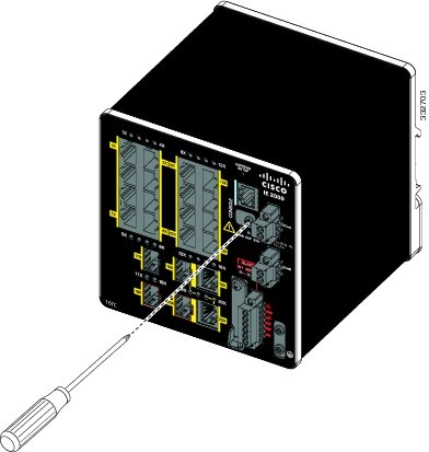
1.![]() Use a Phillips screwdriver to loosen the captive screw on the USB mini-type B console port cover. See Figure 59.
Use a Phillips screwdriver to loosen the captive screw on the USB mini-type B console port cover. See Figure 59.
Figure 59 Removing the USB Mini-Type B Console Port Cover
RJ-45 Console Port
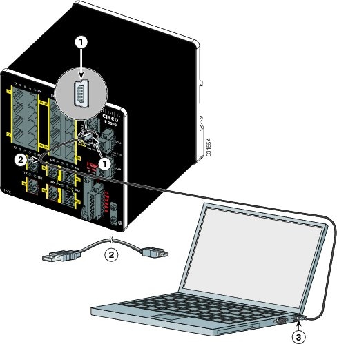
1.![]() Connect the RJ-45-to-DB-9 adapter cable to the 9-pin serial port on the PC. Connect the other end of the cable to the switch console port.
Connect the RJ-45-to-DB-9 adapter cable to the 9-pin serial port on the PC. Connect the other end of the cable to the switch console port.
2.![]() Start the terminal-emulation program on the PC or the terminal. The program, frequently a PC application such as HyperTerminal or ProcommPlus, makes communication between the switch and your PC or terminal possible.
Start the terminal-emulation program on the PC or the terminal. The program, frequently a PC application such as HyperTerminal or ProcommPlus, makes communication between the switch and your PC or terminal possible.
Figure 60 Connecting the Console Cable
|
|
|
3.![]() Configure the baud rate and character format of the PC or terminal to match the console port characteristics:
Configure the baud rate and character format of the PC or terminal to match the console port characteristics:
4.![]() Connect power to the switch as described in Connecting to Power.
Connect power to the switch as described in Connecting to Power.
The PC or terminal displays the bootloader sequence.
5.![]() Press Enter to display the setup prompt.
Press Enter to display the setup prompt.
6.![]() Follow the steps in Completing the Setup Program.
Follow the steps in Completing the Setup Program.
USB Mini-Type B Console Port
1.![]() If you are connecting the switch USB-mini console port to a Windows-based PC for the first time, install a USB driver. See Installing the Cisco Microsoft Windows XP, 2000, Vista, 7, 8, and 10 USB Device Driver for more information.
If you are connecting the switch USB-mini console port to a Windows-based PC for the first time, install a USB driver. See Installing the Cisco Microsoft Windows XP, 2000, Vista, 7, 8, and 10 USB Device Driver for more information.
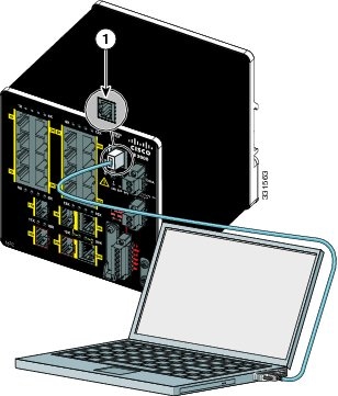
Figure 61 Connecting the USB-Mini Console Cable
|
|
|
||
|
|
|
2.![]() Connect an USB cable to the PC USB port, and connect the other end of the cable to the switch mini-B (5-pin-connector) USB-mini console port. See Connecting the USB-Mini Console Cable.
Connect an USB cable to the PC USB port, and connect the other end of the cable to the switch mini-B (5-pin-connector) USB-mini console port. See Connecting the USB-Mini Console Cable.
3.![]() Identify the COM port assigned to the USB-mini console port:
Identify the COM port assigned to the USB-mini console port:
a.![]() Choose Start > Control Panel > Systems.
Choose Start > Control Panel > Systems.
b.![]() Click the Hardware tab and choose Device Manager. Expand the Ports section. The assigned COM port appears in parenthesis at the end of the line with this entry: Cisco USB System Management Console.
Click the Hardware tab and choose Device Manager. Expand the Ports section. The assigned COM port appears in parenthesis at the end of the line with this entry: Cisco USB System Management Console.
4.![]() Start the terminal-emulation program on the PC or the terminal.
Start the terminal-emulation program on the PC or the terminal.
The program, frequently a PC application such as HyperTerminal or ProcommPlus, makes communication possible between the switch and your PC or terminal.
6.![]() Configure the baud rate and character format of the PC or terminal to match the console port characteristics:
Configure the baud rate and character format of the PC or terminal to match the console port characteristics:
7.![]() Connect power to the switch as described in Connecting to Power.
Connect power to the switch as described in Connecting to Power.
The PC or terminal displays the bootloader sequence.
8.![]() Press Enter to display the setup prompt.
Press Enter to display the setup prompt.
9.![]() Follow the steps in Completing the Setup Program.
Follow the steps in Completing the Setup Program.
Installing the Cisco Microsoft Windows XP, 2000, Vista, 7, 8, and 10 USB Device Driver
A USB device driver must be installed the first time a Microsoft Windows-based PC is connected to the USB console port on the switch. Use this procedure to install the USB driver on Windows XP, Windows 2000, Windows Vista, Windows 7, Windows 8, and Windows 10.
1.![]() Obtain the file Cisco_usbconsole_driver_3_1.zip from the Cisco.com website https://software.cisco.com/download/release.html?mdfid=282979369&softwareid=282855122&release=3.1
Obtain the file Cisco_usbconsole_driver_3_1.zip from the Cisco.com website https://software.cisco.com/download/release.html?mdfid=282979369&softwareid=282855122&release=3.1
The file details are as follows:
–![]() Description: Cisco_usbconsole_driver_3_1.zip
Description: Cisco_usbconsole_driver_3_1.zip
–![]() File Name: Cisco_usbconsole_driver_3_1.zip
File Name: Cisco_usbconsole_driver_3_1.zip
–![]() Size: 14.35 MB (15045453 bytes)
Size: 14.35 MB (15045453 bytes)
–![]() MD5 Checksum: eff2e955edcdc70209e6f9c8f6bd59cd
MD5 Checksum: eff2e955edcdc70209e6f9c8f6bd59cd
2.![]() Unzip the file and install the corresponding exe file.
Unzip the file and install the corresponding exe file.
3.![]() Navigate to the Device Manager window by performing a search in WIndows for Device Manager and opening it.
Navigate to the Device Manager window by performing a search in WIndows for Device Manager and opening it.
4.![]() Connect the USB cable from the Windows PC to the Cisco switch.
Connect the USB cable from the Windows PC to the Cisco switch.
5.![]() From the Device Manager page, expand Ports (COM & LPT). Select USB Serial Port. Right-click and select Update Driver Software...
From the Device Manager page, expand Ports (COM & LPT). Select USB Serial Port. Right-click and select Update Driver Software...
6.![]() In the Update Driver Software window, select Browse my computer for driver software. Then choose Let me pick from a list of device drivers on my computer and click Next.
In the Update Driver Software window, select Browse my computer for driver software. Then choose Let me pick from a list of device drivers on my computer and click Next.
7.![]() Enable Show compatible hardware and choose Cisco Serial as the model. Click Next.
Enable Show compatible hardware and choose Cisco Serial as the model. Click Next.
After the update is completed, Windows displays Windows has successfully updated your driver software.
Uninstalling the Cisco Microsoft Windows XP, 2000, Vista, 7, 8, and 10 USB Driver
Note: Disconnect the switch console terminal before uninstalling the driver.
1.![]() Run setup.exe for Windows 32-bit or setup(x64).exe for Windows-64bit.
Run setup.exe for Windows 32-bit or setup(x64).exe for Windows-64bit.
3.![]() When the InstallShield Wizard for Cisco Virtual Com appears, click Next.
When the InstallShield Wizard for Cisco Virtual Com appears, click Next.
4.![]() When the Program Maintenance window appears, select the Remove radio button.
When the Program Maintenance window appears, select the Remove radio button.
6.![]() When the Remove the Program window appears, click Remove.
When the Remove the Program window appears, click Remove.
If a User Account Control warning appears, click Allow - I trust this program to proceed.
7.![]() When the InstallShield Wizard Completed window appears, click Finish.
When the InstallShield Wizard Completed window appears, click Finish.
Entering the Initial Configuration Information
To set up the switch, you must complete the setup program, which runs automatically after the switch is powered on. Assign an IP address and any other configuration information necessary for the switch to communicate with the local routers and the Internet. This information is also required if you plan to use Device Manager or Cisco Network Assistant to configure and manage the switch.
IP Settings
Gather this information from your network administrator before completing the setup program:
Completing the Setup Program
To complete the setup program and to create an initial configuration for the switch:
1.![]() Enter Yes at these two prompts:
Enter Yes at these two prompts:
2.![]() Enter a hostname for the switch, and press Return.
Enter a hostname for the switch, and press Return.
On a command switch, the hostname is limited to 28 characters; on a member switch, it is limited to 31 characters. Do not use -n, where n is a number, as the last character in a hostname for any switch.
3.![]() Enter an enable secret password, and press Return.
Enter an enable secret password, and press Return.
The password can be from 1 to 25 alphanumeric characters, can start with a number, is case sensitive, allows spaces, but ignores leading spaces. The secret password is encrypted, and the enable password is in plain text.
4.![]() Enter an enable password, and press Return.
Enter an enable password, and press Return.
5.![]() Enter a virtual terminal (Telnet) password, and press Return.
Enter a virtual terminal (Telnet) password, and press Return.
The password can be from 1 to 25 alphanumeric characters, is case sensitive, allows spaces, but ignores leading spaces.
6.![]() (Optional) Configure Simple Network Management Protocol (SNMP) by responding to the prompts.
(Optional) Configure Simple Network Management Protocol (SNMP) by responding to the prompts.
You can also configure SNMP later through the CLI, Device Manager, or the Cisco Network Assistant application.
To configure SNMP later, enter no.
7.![]() Enter the interface name (physical interface or VLAN name) of the interface that connects to the management network, and press Return.
Enter the interface name (physical interface or VLAN name) of the interface that connects to the management network, and press Return.
For this release, always use vlan1 as that interface.
8.![]() Configure the interface by entering the switch IP address and subnet mask and pressing Return.
Configure the interface by entering the switch IP address and subnet mask and pressing Return.
The IP address and subnet masks shown here are examples.
9.![]() Enter Y to configure the switch as the cluster command switch. Enter N to configure it as a member switch or as a standalone switch.
Enter Y to configure the switch as the cluster command switch. Enter N to configure it as a member switch or as a standalone switch.
If you enter N, the switch appears as a candidate switch in the Cisco Network Assistant GUI. You can configure the switch as a command switch later through the CLI, Device Manager, or the Cisco Network Assistant application.
To configure it later, enter no.
You have now completed the initial configuration of the switch, and the switch displays its initial configuration script:
10.![]() Make your selection, and press Return.
Make your selection, and press Return.
After you complete the setup program, the switch can run the default configuration that you created. To change this configuration or perform other management tasks, use one of these tools:
■![]() Cisco Network Assistant (for one or more switches)
Cisco Network Assistant (for one or more switches)
To use the CLI, enter commands at the Switch > prompt through the console port by using a terminal emulation program or through the network by using Telnet.
For configuration information, see the Cisco IE 2000 Switch Software Configuration Guide or the Cisco IE 2000 Switch Command Reference.
To use the Cisco Network Assistant, see the Getting Started with Cisco Network Assistant guide on Cisco.com.
 Feedback