Overview
Provides information about the front panel components, their LEDs, and the status of these LEDs available on the C9610 supervisor engines.
This section describes the front panel components of the Cisco C9610 supervisor engine modules.
Cisco C9610 Supervisor Install Note
Provides information about the front panel components, their LEDs, and the status of these LEDs available on the C9610 supervisor engines.
This section describes the front panel components of the Cisco C9610 supervisor engine modules.
The front panel of the supervisor module provides two types of console ports.
RJ-45 console port: This port provides universal asynchronous receiver/transmitter (UART) support to access the route processor with a serial console running at 9600 baud rate with 8 bits for data, no parity bit, and 1 stop bit.
USB C console port: This port provides direct access to the CLI of the switch. It connects a computer or terminal directly to the Cisco device for configuration purposes. This port also enables terminal communication to configure routers, switches, firewalls, or other Cisco network devices.
Only one of the consoles is active at a time. When a USB host (PC) is plugged into the USB console port, the hardware automatically switches over to use the USB console. Only a PC that has the necessary USB console device driver causes the USB console to become active. Plugging in a PC that does not have the USB console driver support does not cause a switchover. When the USB cable is removed, or the PC deactivates the USB connection, or a host is not detected on the USB console, the hardware automatically switches to the RJ-45 console interface.
The console port allows you to
configure the switch from the CLI,
configure SNMP agent parameters, and
monitor network statistics and errors.
The supervisor module provides two types of management ports, 10/100/1000BASE-T RJ-45 port and 10G SFP+ port. The RJ-45 and SFP+ management ports provide out-of-band (OOB) Ethernet network connectivity, which enables you to use the CLI to manage the switch using its IP address. The management ports support TFTP image downloading, network management, SNMP, Telnet, and Secure Shell (SSH) connections.
SFP+ management port: This port is a fiber port that is referred to as TenGigabitEthernet 0/1 port. C9610-SUP-3 and C9610-SUP-3XL modules has one SFP+ port that supports 10G speeds.
Ethernet management port: This port is a copper Ethernet port that is referred to as GigabitEthernet0/0 (Gi0/0) port. The Ethernet management port supports speeds up to 10/100/1000 Mbps and is set to auto-negotiate.
Based on the cable and connectors that you are using, you can use one of these ports to connect the management interface to the network. Use only one of these management ports; the switch does not support the use of both management ports. By default, the Ethernet management port is enabled.
Use the management port instead of the console port for network management. The switch cannot route packets from a management port to a network port, and from a network port to a management port. To obtain this, the management interface is automatically placed in a separate routing domain or virtual routing and forwarding (VRF) domain, called Mgmt-vrf. The devices support OOB management through the Mgmt-vrf, which is used to segment management traffic from the global routing table of the switch.
When managing a switch, connect the PC to the management port of the supervisor engine.
A recessed access button is available on the front panel of the supervisor module to reset and restart the module. Using a pin, press and hold the button inwards for 5 seconds to reset and restart the module.
The Cisco C9610 supervisor engine modules have an optional, built-in, front-facing, passive Radio Frequency Ientification (RFID) tag that uses Ultra High Frequency (UHF) RFID technology and requires an RFID reader with compatible software. It provides auto-identification capabilities for asset management and tracking. The RFID tags are compatible with the Generation 2 GS1 EPC Global Standard and are ISO 18000-6C compliant. They operate in the 860- to 960-MHz UHF band. For more information, see Radio Frequency Identification (RFID) on Cisco Catalyst 9000 Family Switches White Paper.
For Cisco C9610 series smart switches, the RFID tag is optional. Based on your requirements, you can choose to order the switch with or without an RFID tag at the time of purchase.
This section describes the LEDs on C9610 supervisor engine.
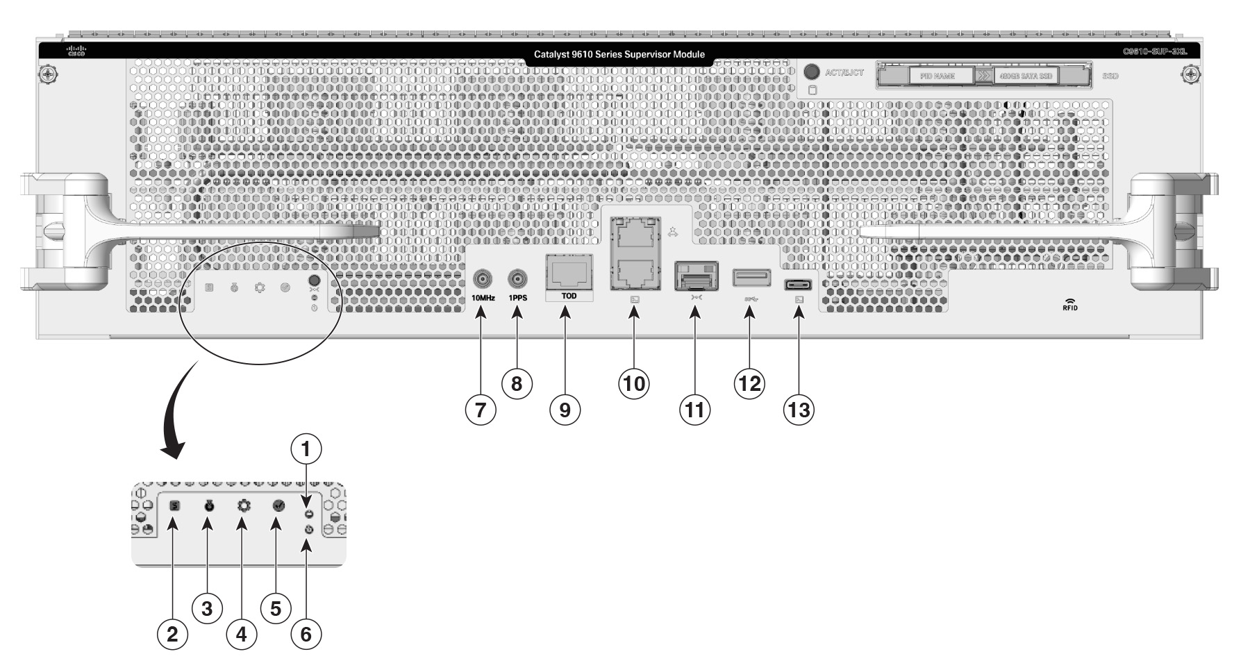
| 1 |
Status LED |
5 |
Mode button
|
| 2 |
Blue beacon LED |
6 |
Reset button |
| 3 |
System LED |
7 |
SSD Eject/Status LED |
| 4 |
Active LED |
- |
- |
This section describes the LEDs and their status. All these LEDs are on the front panel of the supervisor engine.
| LED type |
LED position or color |
Status |
|---|---|---|

Status LED |
Green |
Indicates that all the diagnostic tests have passed after image booting. |
| Amber |
Indicates a major environmental warning. |
|
| Red |
Indicates a fault in the module due to a parity error, failed diagnostic tests, or hardware failure. |
|
| Off |
Indicates that the supervisor module is disabled or is not powered up. |
|

Blue beacon LED |
Solid blue |
Identifies the supervisor module receiving the beacon signal. By default the blue beacon LED is off. You needs to switch it on using the CLI. |

System LED |
Green |
Indicates that the environmental monitors are normal. |
| Amber |
Indicates a minor fault such as a partial power supply or fan failure. |
|
| Red |
Indicates a major fault, for example, situations where the temperature of the supervisor module exceeds the critical threshold. |
|

|
Green |
Indicates that the supervisor module is operational, and is functioning as the active supervisor in redundant supervisor module configurations. |
| Amber |
Indicates one of the following:
|
|
| Mode button |
Not supported |
|
| Reset button |
Reset button |
|
| SSD LED |
Green |
SSD is operational. |
| Yellow |
Indicates that the SSD is being unmounted. |
|
| Amber |
SSD is unmounted. |
|
| Off |
SSD is not available in the supervisor engine. |
|
The Cisco C9610 supervisor engine modules support pluggable Serial Advanced Technology Attachment (SATA) Solid State Drive (SSD) modules. The SATA SSD module slot is located on the front panel of the supervisor engine.
The SATA module is a field replaceable unit (FRU). A hot-swap button on the front panel of the supervisor engine initiates the removal of the SATA module. You must press the button to safely eject the SSD from the supervisor engine.
The SSD module storage capacity ranges are 240GB, 480GB and 960GB.
The USB 3.0 Type A port provides access to external USB flash devices (also known as thumb drives or USB keys). The port supports Cisco USB flash drives with capacities from 64MB to 16GB. USB devices with port densities of 64 MB, 128 MB, 256 MB, 1 GB, 4 GB, 8 GB, and 16 GB are supported. The port provides 2.5 W of power to the device connected to the port.
Cisco IOS XE software provides standard file system access to the flash device, such as read, write, erase, and copy, as well as the ability to format the flash device with a FAT file system.
These guidelines apply when using USB flash drives.
There must at least be one partition on the USB flash drive. If the drive has more than one partition, only the first partition is visible in the system (Cisco IOS XE).
If you partition the flash drive, we recommend that you use a Linux system to perform this task. This ensures that the first partition is a usable partition when connected to the switch.
Using a Windows or MacBook machine utility to perform this task may result in two partitions on the drive by default (partition for system information + actual usable partition). When such a flash drive is connected to the switch, the system displays only the first system information partition, and not the actual usable partition.
The USB Type C port provides console connection using a USB C cable. It functions as a host to manage connected peripherals.
A 10MHz (I/O) DIN connector is an interface port used for precise frequency synchronization in networking equipments. This port can be configured as input ports from an external clocking and timing source, like GPS.
This interface port is not enabled.
The1PPS (I/O) DIN connector is an interface that inputs or outputs a One Pulse Per Second (1PPS) timing signal for precise time synchronization, using a DIN-style 1.0/2.3 coaxial connector typically with 50-ohm impedance.
This interface port is not enabled.
A TOD PTP RJ-45 port is a physical Ethernet port that supports Precision Time Protocol (PTP) timing synchronization and Time of Day (TOD) functions using an RJ-45 connector.
TOD refers to a time source or time-stamping capability available at the hardware or system level for precise timekeeping. It may be used in conjunction with PTP to obtain and distribute exact time-of-day information across devices.
This interface port is not enabled.