Overlay: Distributed Anycast Bridged

Overview: Distributed Anycast Gateway bridged overlay networks

In modern enterprise campus environments, most application traffic flows between wired and wireless users and between resources that are hosted within on-premises data centers or across cloud. Network administrators build structured IP addressing plans with VLAN and subnet on a per-distribution block and enable segmentation through routed overlay or selectively stretching flood-free IP subnets with Distributed Anycast Gateway Routed VXLAN fabric network.

With the digitally evolving IP-everywhere networks, in some scenarios network administrators are mandated to maintain modern fabric networks, while supporting scarce VLAN segments with legacy enterprise network applications and endpoints operating at link-layer without IP addresses. The Distributed Anycast Gateway (DAG) technology supports classic methods to extend the Layer 2 flood-boundary for selective VLANs over the dynamic Layer 2 VXLAN tunnels.

The DAG-bridged overlay networks stretch IP subnets and the Layer 2 VLAN flood-boundary with traditional Integrated Routing and Bridging (IRB) function between targeted Cisco Catalyst 9000 series switches implemented in EVPN multihoming fabric mode. The DAG-bridged overlay networks extend the Layer 2 flood boundary across fabric networks for all endpoints including hosts with and without IP addresses.

Cisco Catalyst 9000 series switches support the coexistence of routed, DAG-routed and DAG-bridged overlay networks that provide the flexibility to scale fabric networks while enabling enterprise application requirements.

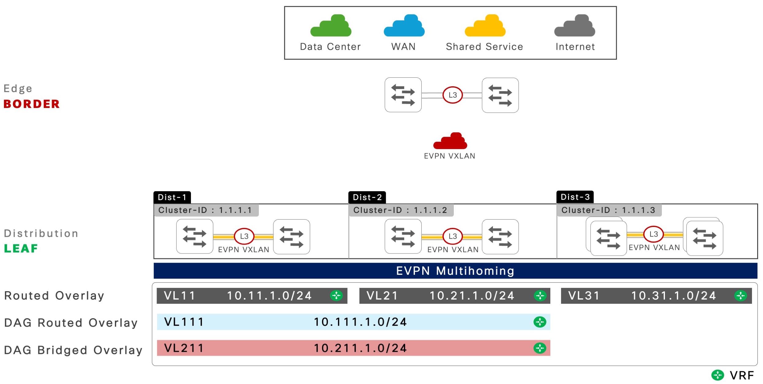
The following figure shows a reference EVPN multihoming network with DAG-bridged overlay for extending Layer 2 flood-boundary for a specific VLAN or IP subnet between pairs of Cisco Catalyst 9000 series switches.

Figure 1. EVPN multihoming with DAG-bridged overlay fabric network

EVPN multihoming with DAG-bridged overlay fabric network

Guidelines for DAG bridged overlay networks

Follow these guidelines when planning for DAG bridged overlay networks.

  • Extended bridge-domain boundaries build larger Layer 2 flood domains.

  • The DAG bridge mode is suggested for the deployment of selective VLANs or subnets based on technical requirements, such as non-IP and silent hosts.

Refer to the downstream Layer 2 network access device product datasheet to determine the MAC address scale numbers.

Understanding DAG bridged overlay networks

Based on business requirements, enterprise networks have the flexibility to support unique per-VLAN basis overlay functions. Routed overlay is proven and recommended for the large-scale overlay networks, DAG-routed overlay provides flexible Layer 2 flood-free IP subnet stretch for selective networks, and the DAG bridge overlay addresses non-routable legacy endpoints and applications by extending the Layer 2 network across the fabric.

Cisco Catalyst 9000 series switches support the coexistence of routed, Distributed Anycast Gateway-routed, and Distributed Anycast Gateway-bridged overlay networking options within the same macro-segmented IP VRF and the micro-segmented VXLAN GPO-enabled environment.

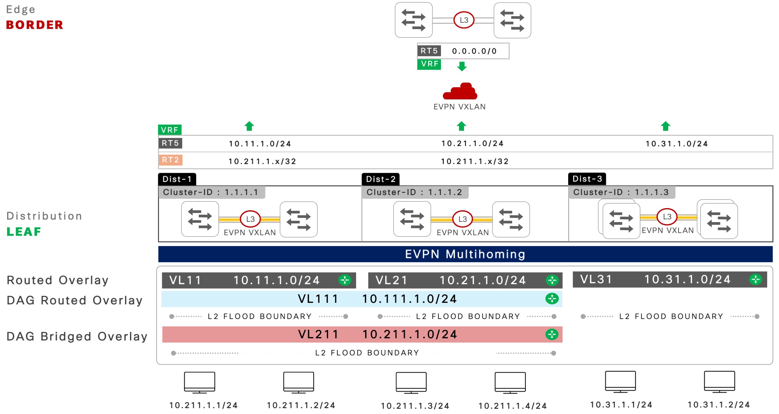
The following figure illustrates the characteristics of an EVPN multihoming network with DAG bridged overlay fabric.

Figure 2. Key characteristics of a DAG bridged fabric overlay network

Fabric network characteristics of a DAG-bridged overlay network

Hierarchical BGP control plane

The recommended deployment consideration to support controlled route management between EVPN multihoming peers and spine switches in large-scale campus networks is the two-tier hierarchical BGP control plane. Each BGP peering layer manages domain-specific EVPN routes to enable downstream non-blocking and all-active Layer 2 multipath networks, and manages the advertising of fabric network prefixes to enable secure global network access connectivity in core networks.

For more information, refer to the Hierarchical BGP Sessions chapter.

EVPN multihoming

Layer 2 networks with EVPN multihoming functions independent of the fabric core EVPN fabric network. A pair of Cisco Catalyst 9000 series switches in each distribution layer builds and manages EVPN multihoming in each redundancy group.

The unified Layer 2 Ethernet Segment (ES) EtherChannel connection to downstream network device can carry VLANs that are mapped to routed, selective-stretched subnets with DAG-routed overlay and advertised in the fabric core or can continue to be traditional underlay IP networks.

Layer 2 broadcast network boundary

The DAG-bridged overlay networks provide unified Layer 2 or Layer 3 network boundary as the routed overlay and the traditional underlay campus network. The Layer 2 bridge domain and the blast radius remain contained between Layer 2 access and EVPN multihoming-enabled distribution layer systems.

A pair of Cisco Catalyst 9000 series switches in the distribution layer network dynamically builds the Layer 2 VXLAN tunnel using ingress replication mode to extend Broadcast, Unknown Unicast and Multicast (BUM) traffic. With built-in loop-detection and prevention techniques, EVPN multihoming-enabled networks support a secure and scalable Layer 2 network over traditional STP based networks.

Stretched IP subnet and gateway redundancy

The DAG routed overlay network enables stretching an IP subnet between targeted EVPN multihoming network devices that support distributed connected IP or non-IP reachability across fabric networks. The selective group of Cisco Catalyst 9000 series switches in EVPN multihoming mode shares common IPv4 or IPv6 subnet function to support intra-subnet host communication based on the fabric host-routing or MAC address tables while providing load-sharing and gateway redundancy with Anycast gateway as a routed overlay.

Spine route policy

The IPv4 or IPv6 subnets and Layer 2 flood domains stretch across multiple IP gateway systems and demand a non-condensed host-level MAC-only or MAC-IP prefix to support seamless data communication across fabrics and beyond.

Large scale EVPN multihoming-enabled fabric networks benefit from the enforcement of the route policy on leaf switches towards the spine switches.

The iBGP or eBGP prefix advertisement to spine switches in the fabric core is limited to the advertising of RT-2 host prefixes and RT-5 network prefixes along with EAD per-ES RT-1 routes. Cisco Catalyst 9000 series switches in EVPN multihoming mode retain unfiltered routing with an iBGP peering session with remote ES switches for non-blocking Layer 2 multipath EtherChannel.


Note


Routed overlay networks are recommended for better scale, performance, and resiliency.


Configure DAG bridged overlay networks

This section provides sequential configuration tasks to successfully implement a DAG bridged overlay fabric network.

The BGP EVPN VXLAN-enabled fabric core network must be built with a reliable underlay IP and Layer 2 EVPN multihoming network as prerequisites.

For more information on configuration guidelines for underlay and Layer 2 multihoming.

Configure IP VRFs

This task shows how to configure a logically segmented virtual network with an IP VRF to exchange IPv4 or IPv6 network prefixes across all VTEPs in the fabric core network.


Note


This configuration task is optional if IP VRFs are already configured on Cisco Catalyst 9000 series switches as part of the routed overlay network configuration.


Procedure

  Command or Action Purpose

Step 1

enable

Example:

Device> enable

Enables privileged EXEC mode.

  • Enter your password if prompted.

Step 2

configure terminal

Example:

Device# configure terminal

Enters global configuration mode.

Step 3

vrf definition vrf-name

Example:

Device(config)# vrf definition green

Configures a new virtual routing and forwarding (VRF) instance and enters VRF configuration mode. 

Step 4

rd vpn-route-distinguisher

Example:

Device(config-vrf)# rd 10.200.255.101:101

Configures a route distinguisher with a distinct value across all fabric devices.

Step 5

address-family ipv4 [multicast | unicast]

Example:

Device(config-vrf-af)# address-family ipv4 unicast

Enters IPv4 unicast address-family configuration mode.

Step 6

route-target [both | export | import] route-target-ext-community

Example:

Device(config- vrf-af)# route-target 65101:101

Configures an overlay IPv4 import and export routing policy that matches the extended community value.

  • The default is both and will auto-generate both import and export command line with the configured community value.

Step 7

route-target [both | export | import] route-target-ext-community stitching

Example:

Device(config- vrf-af)# route-target 65101:101 stitching

Configures an IPv4 routing import and export overlay policy that matches the extended community value and enables extended NLRI types for BGP EVPN VXLAN-enabled networks.

  • The default is both

Step 8

address-family ipv6 [multicast | unicast]

Example:

Device(config- vrf-af)# address-family ipv6 unicast

Enters IPv6 unicast address-family configuration mode.

Step 9

route-target [both | export | import] route-target-ext-community

Example:

Device(config- vrf-af)# route-target 65101:101

Configures an IPv6 routing import and export overlay policy that matches the extended community value.

  • The default is both and will auto-generate both import and export command line with the configured community value.

Step 10

route-target [both | export | import] route-target-ext-community stitching

Example:

Device(config- vrf-af)# route-target 65101:101 stitching

Configures an IPv6 routing import and export overlay policy that matches the extended community value and enables extended NLRI types for BGP EVPN VXLAN-enabled networks.

  • The default is both .

Step 11

end

Example:

Device(config- vrf-af)# end

Exits IPv6 unicast address-family configuration mode and returns to privileged EXEC mode.

Configure core VLAN and SVI interfaces

This task shows how to configure core VLAN and SVI interfaces for each of the IP VRFs used for VXLAN encapsulation and decapsulation functions between the downstream non-VXLAN network and remote VXLAN-enabled VTEPs. The task also shows how to configure the NVE interface and bind the L3VNI ID to a logical interface.


Note


Skip this task if you have already configured core VLAN and SVI interfaces as part of the routed overlay network configuration.


Procedure

  Command or Action Purpose

Step 1

enable

Example:

Device> enable

Enables privileged EXEC mode.

  • Enter your password if prompted.

Step 2

configure terminal

Example:

Device# configure terminal

Enters global configuration mode.

Step 3

vlan id

Example:

Device(config)# vlan 101

Configures a dedicated VLAN ID for IP VRF core routing. This VLAN must not be used for any other purpose, and it is recommended to be pruned from Layer 2 trunk ports.

Step 4

vlan configuration id

Example:

Device(config)# vlan configuration 101

Configures a core VLAN to assign the Layer 3 VNI ID and enters VLAN configuration mode.

Step 5

member vni l3vni-id

Example:

Device(config-vlan)# member vni 11101

Configures a unique Layer 3 VNI ID for a specific IP VRF.

For example, VRF green has the dedicated VLAN, 101 and Layer 3 VNI, and these IDs must not be shared with other IP VRFs on the same system.

  • It is recommended that all other VTEPs must have a Layer 3 VNI ID for the same IP VRF.

Step 6

exit

Example:

Device(config-vlan)# exit

Exits VLAN configuration mode and returns to global configuration mode

Step 7

interface vlan id

Example:

Device(config)# interface vlan 101

Configures a core VLAN SVI interface and assigns it to an IP VRF.

  • The core VLAN SVI MAC address is used to support routed MAC (RMAC) for Layer 3 overlays.

Step 8

vrf forwarding vrf-name

Example:

Device(config-if)# vrf forwarding green

Maps the IP VRF to a core VLAN SVI interface.

Step 9

ip unnumbered id

Example:

Device(config-if)# ip unnumbered Loopback0

Configures an unnumbered IPv4 address from an underlay logical interface, for example, Loopback0.

Step 10

no autostate

Example:

Device(config-if)# no autostate

Disables autostate on the interface.

  • In EVPN deployments, a VLAN used for a core-facing SVI, should not be allowed in any trunks. For a core-facing SVI to function correctly, the no autostate  command must be configured for the SVI.

Step 11

exit

Example:

Device(config-if)# exit

Exits interface configuration mode and returns to global configuration mode.

Step 12

interface nve id

Example:

Device(config)# interface nve 1

Configures a virtual NVE interface to bind one or more L2VNIs and enables system-wide VXLAN forwarding function from the L3VNIs.

  • Enters interface configuration mode.

Step 13

source-interface id

Example:

Device(config-if)# source-interface Loopback0

Configures a Loopback interface as the source to enable data communication over a VXLAN tunnel.

Step 14

host-reachability protocol bgp

Example:

Device(config-if)# host-reachability protocol bgp

Configures BGP as the host-reachability control plane protocol on this interface.

Step 15

member vni l3vni-id vrf vrf-name

Example:

Device(config-if)# member vni 11101 vrf green

Binds the L3VNI to the IP VRF under the NVE interface.

Step 16

end

Example:

Device(config-if)# end

Exits interface configuration mode and returns to privileged EXEC mode.

Configure a DAG bridged overlay MAC-VRF

This task shows how to configure a MAC VRF and route-target policy to selectively exchange prefixes between a pair of EVPN multihoming-enabled Catalyst 9000 series switches in a single cluster.

Follow the step-by-step configuration to enable DAG bridged MAC VRFs. Refer to "EVPN Multihoming for Non-Fabric Networks" chapter in the High Availability configuration guide for a complete Layer 2 network configuration.

Procedure

  Command or Action Purpose

Step 1

enable

Example:

Device> enable

Enables privileged EXEC mode.

  • Enter your password if prompted.

Step 2

configure terminal

Example:

Device# configure terminal

Enters global configuration mode.

Step 3

l2vpn evpn instance id vlan-based

Example:

Device(config)# l2vpn evpn instance 211 vlan-based

Configures a L2VPN EVPN virtual instance with a unique ID. Typically, the ID value is the same as the VLAN ID, for example, data VLAN ID 211.

  • Enters EVPN instance configuration mode.

Step 4

encapsulation vxlan

Example:

Device(config-evpn-evi)# encapsulation vxlan

Enables VXLAN encapsulation to bridge inter-ES data between two systems.

Step 5

route-target {export | import | both} route-target-ext-community

Example:

Device(config-evpn-evi)# route-target both 1.1.1.1:211

Configures a MAC or IP routing import and export policy that matches the extended community value.

  • The recommended format for EVPN multihoming cluster VLAN ID is Cluster-1 ID with 1.1.1.1 and DAG-routed VLAN ID 211 can result in the MAC VRF route-target 1.1.1.1:211.

    The default is both and it auto-generates the import and export command lines with the configured community value.

Step 6

route-target {export | import | both} route-target-ext-community

Example:

Device(config-evpn-evi)# route-target import 1.1.1.2:211

Configures inter-cluster DAG bridging with a MAC or IP routing import-only policy that matches the extended community value.

  • The recommended format for EVPN multihoming cluster VLAN ID is Cluster-1 ID with 1.1.1.2 and DAG-routed VLAN ID 211 can result in the MAC VRF route-target 1.1.1.2:211.

Step 7

no auto-route-target

Example:

Device(config-evpn-evi)# no auto-route-target

Disables auto route target with the manual route target configured in Step 5 for the DAG-routed overlay MAC VRF.

  • The default is auto-generated route target in ASN:L2VPN instance ID format.

    Default enabled with auto-generated RT in ASN:L2VPN Instance ID format.

Step 8

advertise mac enable

Example:

Device(config-evpn-evi)# advertise mac enable 

Enables the originating and advertising of the MAC-only route to enable non-IP data communication.

Step 9

replication-type {ingress | static}

Example:

Device(config-evpn-evi)# replication-type static

Enables underlay BUM replication type with multicast for scalable fabric networks.

Step 10

end

Example:

Device(config-evpn-evi)# end

Exits EVPN instance configuration mode and returns to privileged EXEC mode.

Configure access SVI interfaces

This section provides step-by-step instructions to configure Cisco Catalyst 9000 series switches in EVPN multihoming mode.

The DAG bridge mode provides a single-unified IP gateway system through multiple leaf network devices. The intra subnet IP or non-IP host communication follows standard remote MAC-to-IP binding resolution, while all inter subnet IP communication is routed through the anycast gateway IP address.

Procedure

  Command or Action Purpose

Step 1

enable

Example:

Device> enable

Enables privileged EXEC mode.

  • Enter your password if prompted.

Step 2

configure terminal

Example:

Device# configure terminal

Enters global configuration mode.

Step 3

interface vlan id

Example:

Device(config)# interface Vlan 211

Configures a Layer 3 SVI interface ID and enters interface configuration mode.

Step 4

vrf forwarding vrf-name

Example:

Device(config-if)# vrf forwarding green

Maps the IP VRF to a core VLAN SVI interface.

Step 5

ip address ip-address mask

Example:

Device(config-if)# ip address 10.211.1.254 255.255.255.0

Assigns an IPv4 gateway address and mask for selected VLANs.

  • The anycast gateway is auto enabled with common addresses between ES systems.

Step 6

ipv6 address ipv6-address mask

Example:

Device(config-if)# ipv6 address 2001:10:211:1::f/64

Assigns an IPv6 gateway address and prefix for selected VLANs.

  • The anycast gateway is auto enabled with common addresses between ES systems.

Step 7

end

Example:

Device(config-if)# end

Exits interface configuration mode and returns to privileged EXEC mode.

Configure a spine policy for DAG bridged overlay networks

This task provides step-by-step instructions to configure a pair of ES switches with an outbound spine EVPN route policy. The route policy enables controlled EVPN route advertisement by a pair of ES switches, independent of iBGP or eBGP spine-peering session type.

The spine route-map policy to permit RT-5 prefix for routed overlay can be expanded with a new sequence to limit Cisco Catalyst 9000 series switches advertising the Route-Type 1 and Route-Type 2 (that includes MAC-only and MAC-IP) prefixes for network-wide host route propagation based on DAG MAC VRF route target values.

The iBGP peering with EVPN multihoming system unfiltered EVPN route exchange to build and maintain non-blocking Layer 2 multipath network.

Procedure

  Command or Action Purpose

Step 1

enable

Example:

Device> enable

Enables privileged EXEC mode.

  • Enter your password if prompted.

Step 2

configure terminal

Example:

Device# configure terminal

Enters global configuration mode.

Step 3

ip extcommunity-list [expanded list-name {permit | deny} [regular-expression] | standard-lit-number standard-list-name {permit | deny} [rt extended-community-value] [soo extended-community-value]

Example:

Device(config)# ip extcommunity-list expanded DAG-BRIDGED-OVERLAY-EXTCOMM
 permit 1.1.1.1:211

Configures an extended IP community list to permit the DAG-bridge MAC VRF route-target values.

  • A single IP extended community can be configured with a single RT value or can be configured through regular expressions that match multiples. For example, 21[1-9] for 211-219 DAG-bridged VLAN ID range.

Step 4

route-map name [permit | deny] sequence-number

Example:

Device(config)# route-map SPINE-ROUTE-POLICY-OUT permit 30

Creates a route-map rule with permit or deny match criteria and enters route-map configuration mode.

  • The optional sequence-number argument indicates the order of processing of the route-map rule.

Step 5

description description

Example:

Device(config-route-map)# description DAG BRIDGED OVERLAY – VL211

(Optional) Adds a description for the route-map sequence.

Step 6

match evpn route-type [1-8 | 2-mac-ip | 2-mac-only]

Example:

Device(config-route-map)# match evpn route-type 1

Configures an EVPN route policy sequence to permit advertising the local EAD per Ethernet Segment (ES) prefixes RT-1) for each local ES.

Step 7

match evpn route-type [1-8 | 2-mac-ip | 2-mac-only]

Example:

Device(config-route-map)# match evpn route-type 2

Configures an EVPN route policy sequence to permit advertising the local IPv4 or IPv6 host and MAC prefixes (RT-2) mapped to any IP VRF.

Step 8

exit

Example:

Device(config-route-map)# exit

Exits route-map configuration mode and returns to global configuration mode.

Step 9

router bgp autonomous-system-number

Example:

Device(config)# router bgp 65101

Configures BGP autonomous system numbers using 2-bytes or 4-bytes in asplain and asdot formats and enters router configuration mode. 

For more information, refer to

Step 10

address-family l2vpn evpn

Example:

Device(config-router)# address-family l2vpn evpn

Enters BGP L2VPN address-family configuration mode.

Step 11

neighbor spine-loopback-address route-map name out

Example:

Device(config-router-af)# neighbor 10.200.255.3 route-map SPINE-ROUTE-POLICY-OUT out

Applies outbound route-map policy to each spine peer to limit the advertising of the RT-5 prefix.

Step 12

end

Example:

Device(config-router-af)# end

Exits BGP L2VPN address-family configuration mode and returns to privileged EXEC mode.

Configure IP VRF address family routing under BGP

This task shows how to advertise network prefixes in IPv4 and IPv6 address-family configurations.

Procedure

  Command or Action Purpose

Step 1

enable

Example:

Device> enable

Enables privileged EXEC mode.

  • Enter your password if prompted.

Step 2

configure terminal

Example:

Device# configure terminal

Enters global configuration mode.

Step 3

router bgp autonomous-system-number

Example:

Device(config)# router bgp 65101

Configures BGP autonomous system numbers using 2-bytes or 4-bytes in asplain and asdot formats and enters router configuration mode.

For more information, refer to

Step 4

address-family ipv4 vrf vrf-name

Example:

Device(config-router)# address-family ipv4 vrf green

Enables IPv4 address-family for a VRF instance to enable IPv4 network prefix routing in overlay.

Step 5

advertise l2vpn evpn

Example:

Device(config-route-af)# advertise l2vpn evpn

Enables advertising the IPv4 network prefix routing between IPv4 VRF instances and EVPN fabric core networks.

Step 6

redistribute connected [metric |route-map] name

Example:

Device(config-route-af)# redistribute connected

Configures IPv4 address-family to advertise all local connected IPv4 network prefixes in EVPN fabric network.

  • Network prefixes can be advertised by the network command as an alternative.

Step 7

exit

Example:

Device(config-route-af)# exit

Exits IPv4 address-family configuration mode and returns to router configuration mode

Step 8

address-family ipv6 vrf vrf-name

Example:

Device(config-router)# address-family ipv6 vrf green

Enables IPv6 address-family for a VRF instance to enable IPv6 network prefix routing in overlay.

Step 9

advertise l2vpn evpn

Example:

Device(config-route-af)# advertise l2vpn evpn

Enables IPv6 network prefix routing between IPv6 VRF instances and EVPN fabric core networks.

Step 10

redistribute connected [metric |route-map] name

Example:

Device(config-route-af)# redistribute connected

Configures an IPv6 address-family to advertise all local connected IPv6 network prefixes in EVPN fabric network.

  • Network prefixes can be advertised by the network command, as an alternative.

Step 11

end

Example:

Device(config-route-af)# end

Exits IPv6 address-family configuration mode and returns to privileged EXEC mode.

Verify the DAG bridged overlay network configuration

This section provides examples to verify the DAG-bridged overlay network configuration and states of VTEPs.

The command output may be truncated to focus on critical information for a Day-2 operation and troubleshooting.

IP VRF networks: Verifies the locally configured IP VRF and the associated physical or logical interface bindings to a virtual network on VTEPs including leaf and border devices. The interface binding includes the network edge VLANs connecting to endpoints, and network devices, along with a single core VLAN (VLAN 101) of an IP VRF.

 
ES-1# show vrf green
 
  Name      Default RD               Protocols     Interfaces 
  green     10.200.255.101:101	ipv4	    Vl11 
                                                   Vl211 
                                                   Vl101 
BORDER-1# show vrf green 

  Name     Default RD              Protocols	Interfaces 
  green    10.200.255.1:101	 ipv4	      Vl101 
                                                   Vl1101 

BGP L2VPN EVPN neighbors: Verifies that the two-tier hierarchical iBGP sessions between Cisco Catalyst 9000 series switches in EVPN multihoming mode, and iBGP peering to a pair of spine systems are operational.

The following command output shows iBGP peering with a pair of spines switches, 10.100.255.3 and 10.100.255.4 and direct iBGP peering between ES-1, local 10.100.255.101 and ES-2, 10.100.255.102 switches in EVPN multihoming mode is operational.


ES-1# show bgp l2vpn evpn all summary 

BGP router identifier 10.100.255.101, local AS number 65101 
<snip> 
 
Neighbor         V    AS     MsgRcvd  MsgSent   TblVer  InQ   OutQ    Up/Down    State/PfxRcd 
10.100.255.3     4    65101    18        20      104     0      0     00:04:35         2 
10.100.255.4     4    65101    23        25      106     0      0     00:05:19         2 
10.100.255.102   4    65101    51        65      104     0      0     00:04:26         28 


Spine policy: Verifies the VTEP in leaf or border roles implemented in EVPN multihoming mode is configured with a route-map and an outbound policy is applied to each spine, 10.200.255.3.

The spine policy configuration on border switches is optional and not required if the switches are not implemented in EVPN multihoming mode to connect to external network devices, such as firewalls.


ES-1# show bgp l2vpn evpn neighbor 10.200.255.3 policy   
 
Neighbor: 10.200.255.3, Address-Family: L2VPN E-VPN 
 Locally configured policies: 
  send-community extended 
 Inherited polices: 
  route-map EVPN-SPINE-ROUTE-POLICY-OUT out 


L2VPN advertised routes: Verifies the VTEP in leaf or border roles implemented in EVPN multihoming mode is advertising the EVPN prefixes to the spine, 10.200.255.3, based on the applied route-map policy.

The following command output from leaf and border switches confirms the advertising of RT-2-MAC-IP EVPN prefixes, and that no additional EVPN route-types are advertised to the spine switches.


ES-1# show bgp l2vpn evpn neighbor 10.200.255.3 advertised-route   

BGP table version is 7179, local router ID is 10.200.255.101 
<snip> 
     Network          	Next Hop            Metric 	LocPrf  Weight  Path 
 Route Distinguisher: 10.200.255.101:111 
 *>   [2][10.200.255.101:111][0][48][00CCFC4ED1C3][32][10.111.1.1]/24 
                      	0.0.0.0                  	  32768     ? 
Route Distinguisher: 10.200.255.101:111 
 *>   [2][10.200.255.101:111][0][48][00CCFC4ED1C4][32][10.111.1.2]/24 
                      	0.0.0.0                           32768     ? 


Border-1# show bgp l2vpn evpn neighbors 10.200.255.3 advertised-routes  

BGP table version is 2895, local router ID is 10.200.255.1 
<snip> 
     Network          Next Hop            Metric    LocPrf     Weight   Path 
Route Distinguisher: 10.100.255.1:101 (default for vrf green) 
 *>   [5][10.100.255.1:101][0][0][0.0.0.0]/17 
                      21.1.1.1               0          0      65001      ? 
 *>   [5][10.100.255.1:101][0][16][111.1.0.0]/17 
                      21.1.1.1               0          0      65001      ? 
 

MAC-VRF manual route-target: Verifies that the stretched IP-subnet VLAN is limited to import and export of the MAC or IP route matching the local cluster EVPN multihoming peer switch. With auto route-target disabled, the import and export route-target only lists the manual configuration settings.

The following command output confirms that the bidirectional MAC route policy with route-target 1.1.1.1:12 and the default auto-generated ASN instance ID 65101:211 is not listed along with the manual configuration.


ES-1# show l2vpn evpn evi 211 detail 

EVPN instance:          	211 (VLAN Based) 
  RD:                   	10.200.255.101:211 (auto) 
  Import-RTs:           	1.1.1.1:211   1.1.1.2:211  
  Export-RTs:           	1.1.1.1:211 
  Per-EVI Label:        	none 
  State:                	Established 
  Replication Type:     	Static 
 <snip> 

VRF IP routing table: Verifies that the leaf implemented in EVPN multihoming mode is advertising the EVPN prefixes to the spine switch 10.200.255.3 based on the applied route-map policy.

The following command output from the border switch confirms that the pair of EVPN multihoming leaf systems configured in DAG routed overlay, each with two hosts are advertising RT2-MAC-IP. Border switches have a dual-path ECMP to each host to support load-sharing and redundancy for overlay network prefixes. And leaf switches receive the RT-5 network prefix from the IP routing table of IP VRFs in the border systems that confirm the advertising of RT-5 EVPN prefixes.


ES-1# show ip route vrf green bgp
  
Routing Table: green 
<snip> 
 
Gateway of last resort is 10.200.255.2 to network 0.0.0.0 
B*    0.0.0.0/0 	[200/0] via 10.200.255.1, 00:00:32, Vlan101 
                       [200/0] via 10.200.255.2, 00:00:32, Vlan101 
 

Border-1# show ip route vrf green bgp  

Routing Table: green 
<snip> 
Gateway of last resort is 21.1.1.1 to network 0.0.0.0 
 
B*    0.0.0.0/0 [20/0] via 21.1.1.1, 6w0d 
      10.0.0.0/24 is subnetted, 95 subnets 
B        10.111.1.1/32	[200/0] via 10.200.255.102, 00:01:33, Vlan1101 
                    	  [200/0] via 10.200.255.101, 00:01:33, Vlan1101 
B        10.111.1.2/32	[200/0] via 10.200.255.102, 00:01:33, Vlan1101 
                      	[200/0] via 10.200.255.101, 00:01:33, Vlan1101 
B        10.111.1.3/32       [200/0] via 10.200.255.104, 00:01:33, Vlan1101 
                      	[200/0] via 10.200.255.103, 00:01:33, Vlan1101 
B        10.111.1.4/32       [200/0] via 10.200.255.104, 00:01:33, Vlan1101 
                      	[200/0] via 10.200.255.103, 00:01:33, Vlan1101 


Reference configuration for DAG bridged overlay networks

This section provides a reference network design and configuration to implement a DAG bridged overlay fabric network.

This following figure illustrates a reference network design to support scalable EVPN multihoming and fabric core with hierarchical BGP peering, control-plane peering, and selective stretching of an IP subnet between a pair of Cisco Catalyst 9000 series switches deployed in the distribution block with overlay fabric network.

Figure 3. EVPN multihoming: DAG-bridged overlay fabric network

EVPN multihoming: DAG-bridged overlay fabric network

This reference configuration shows a three-step process, from the initial network setup to the successful fabric deployment. Network administrators can follow these steps sequentially for initial deployment and to increment the overlay network configuration as the network demands increase.

Layer 2 EVPN multihoming

The base configuration to build a fabric begins with Layer 2 campus networks using EVPN multihoming technology. This section provides the step-by-step configuration on a pair of Cisco Catalyst 9000 series switches to successfully build a non-blocking all-active Layer 2 network with EVPN multihoming.

Step

ES-1 and ES-2

ES-3 and ES-4

1: Inter-ES Layer 3 EtherChannel

ES-1 
! 
interface Port-Channel 128 
 description CONNECTED TO ES PEER 
 no switchport 
 ip address 10.0.0.0 255.255.255.254 
 ip ospf network point-to-point 
 ip ospf multi-area 0 
 ip ospf 100 area 101 
 ip ospf 100 cost 10 
 carrier-delay msec 0 
 hold-queue 4094 in 
 hold-queue 4094 out 
 evpn multihoming core-tracking 
! 

ES-2 
! 
interface Port-Channel 128 
 description CONNECTED TO EVPN MH SW-2 
 no switchport 
 ip address 10.0.0.1 255.255.255.254 
 ip ospf network point-to-point 
 ip ospf multi-area 0 
 ip ospf 100 area 101 
 ip ospf 100 cost 10 
 carrier-delay msec 0 
 hold-queue 4094 in 
 hold-queue 4094 out 
 evpn multihoming core-tracking 
! 
ES-3 
! 
interface Port-Channel 128 
 description CONNECTED TO ES PEER 
 no switchport 
 ip address 10.0.0.2 255.255.255.254 
 ip ospf network point-to-point 
 ip ospf multi-area 0 
 ip ospf 100 area 102 
 ip ospf 100 cost 10 
 carrier-delay msec 0 
 hold-queue 4094 in 
 hold-queue 4094 out 
 evpn multihoming core-tracking 
! 

ES-4 
! 
interface Port-Channel 128 
 description CONNECTED TO EVPN MH SW-1 
 no switchport 
 ip address 10.0.0.3 255.255.255.254 
 ip ospf network point-to-point 
 ip ospf multi-area 0 
 ip ospf 100 area 102 
 ip ospf 100 cost 10 
 carrier-delay msec 0 
 hold-queue 4094 in 
 hold-queue 4094 out 
 evpn multihoming core-tracking 
! 

2: IGP routing and core interface

ES-1 
! 
router ospf 100 
 router-id 10.200.255.101 
 max-metric router-lsa 
  include-stub summary-lsa 
    external-lsa on-startup wait-for-bgp  
 nsf cisco  
 fast-reroute per-prefix enable 
  prefix-priority low 
 area 101 stub no-summary 
 passive-interface default 
 no passive-interface Port-Channel 128 
 no passive-interface HundredGig1/0/49 
 no passive-interface HundredGig1/0/50 
! 
interface Loopback 0 
 ip address 10.100.255.101 
  255.255.255.255 
 ip ospf 100 area 0 
! 
ES-2 
! 
router ospf 100 
 router-id 10.200.255.102 
 max-metric router-lsa include-stub 
   summary-lsa 
   external-lsa on-startup wait-for-bgp  
 nsf cisco  
 fast-reroute per-prefix enable 
   prefix-priority low 
 area 101 stub no-summary 
 passive-interface default 
 no passive-interface Port-Channel 128 
 no passive-interface HundredGig1/0/49 
 no passive-interface HundredGig1/0/50 
! 
interface Loopback 0 
 ip address 10.100.255.102 255.255.255.255 
 ip ospf 100 area 0 
! 

ES-3 
! 
router ospf 100 
 router-id 10.200.255.103 
 max-metric router-lsa include-stub 
   summary-lsa
   external-lsa on-startup wait-for-bgp  
 nsf cisco  
 fast-reroute per-prefix enable 
   prefix-priority low 
 area 102 stub no-summary 
 passive-interface default 
 no passive-interface Port-Channel 128 
 no passive-interface HundredGig1/0/49 
 no passive-interface HundredGig1/0/50 
! 
interface Loopback 0 
 ip address 10.100.255.103 255.255.255.255 
 ip ospf 100 area 0 
! 
ES-4 
! 
router ospf 100 
 router-id 10.200.255.104 
 max-metric router-lsa include-stub 
  summary-lsa
   external-lsa on-startup wait-for-bgp  
 nsf cisco  
 fast-reroute per-prefix enable 
   prefix-priority low 
 area 102 stub no-summary 
 passive-interface default 
 no passive-interface Port-Channel 128 
 no passive-interface HundredGig1/0/49 
 no passive-interface HundredGig1/0/50 
! 
interface Loopback 0 
 ip address 10.100.255.104 255.255.255.255 
 ip ospf 100 area 0 
! 

3: iBGP routing

ES-1 
! 
router bgp 65101 
 template peer-policy ES-PEER-POLICY 
  send-community both 
 ! 
 template peer-session ES-PEER-SESSION-POLICY 
  remote-as 65101 
  description EVPN-MH-DIST-2-PEER 
  update-source Loopback0 
  fall-over host-route 
 ! 
 bgp router-id interface Loopback0 
 bgp log-neighbor-changes 
 bgp graceful-restart 
 no bgp default ipv4-unicast 
    ES-PEER-SESSION-POLICY 
 ! 
 address-family l2vpn evpn 
  bgp nexthop trigger critical-delay 0 
  neighbor 10.100.255.102 activate 
  neighbor 10.100.255.102 send-community both 
  neighbor 10.100.255.102 inherit peer-policy
    ES-PEER-POLICY 
 ! 
ES-2 
! 
router bgp 65101 
 template peer-policy ES-PEER-POLICY 
  send-community both 
 ! 
 template peer-session ES-PEER-SESSION-POLICY 
  remote-as 65101 
  description EVPN-MH-DIST-2-PEER 
  update-source Loopback0  
  fall-over host-route 
 ! 
 bgp router-id interface Loopback0 
 bgp log-neighbor-changes 
 bgp graceful-restart 
 no bgp default ipv4-unicast 
 neighbor 10.100.255.101 inherit peer-session
    ES-PEER-SESSION-POLICY 
 ! 
 address-family l2vpn evpn 
  bgp nexthop trigger critical-delay 0 
  neighbor 10.100.255.101 activate 
  neighbor 10.100.255.101 send-community both 
  neighbor 10.100.255.101 inherit peer-policy
    ES-PEER-POLICY 
 ! 

ES-3 
! 
router bgp 65101 
 template peer-policy ES-PEER-POLICY 
  send-community both 
 ! 
 template peer-session ES-PEER-SESSION-POLICY 
  remote-as 65101 
  description EVPN-MH-DIST-1-PEER 
  update-source Loopback0  
  fall-over host-route 
 ! 
 bgp router-id interface Loopback0 
 bgp log-neighbor-changes 
 bgp graceful-restart 
 no bgp default ipv4-unicast 
 neighbor 10.100.255.104 inherit peer-session
    ES-PEER-SESSION-POLICY 
 ! 
 address-family l2vpn evpn 
  bgp nexthop trigger critical-delay 0 
  neighbor 10.100.255.104 activate 
  neighbor 10.100.255.104 send-community both 
  neighbor 10.100.255.104 inherit peer-policy
    ES-PEER-POLICY 
 ! 
ES-4 
! 
router bgp 65101 
 template peer-policy ES-PEER-POLICY 
  send-community both 
 ! 
 template peer-session ES-PEER-SESSION-POLICY 
  remote-as 65101 
  description EVPN-MH-DIST-1-PEER 
  update-source Loopback0 
  fall-over host-route 
 ! 
 bgp router-id interface Loopback0 
 bgp log-neighbor-changes 
 bgp graceful-restart 
 no bgp default ipv4-unicast 
 neighbor 10.100.255.103 inherit peer-session
    ES-PEER-SESSION-POLICY 
 ! 
 address-family l2vpn evpn 
  bgp nexthop trigger critical-delay 0 
  neighbor 10.100.255.103 activate 
  neighbor 10.100.255.103 send-community both 
  neighbor 10.100.255.103 inherit peer-policy
    ES-PEER-POLICY 
 ! 

4: Global L2VPN

! 
l2vpn evpn 
advertise mac disable 
anycast-gateway mac auto 
multicast advertise sync-only 
multihoming aliasing disable 
multihoming peering adjacent 
replication-type ingress 
router-id Loopback 0 
! 

! 
l2vpn evpn 
advertise mac disable 
anycast-gateway mac auto 
multicast advertise sync-only 
multihoming aliasing disable 
multihoming peering adjacent 
replication-type ingress 
router-id Loopback 0 
! 

5: Routed VLAN and MAC VRF

! 
vlan 11 
 name ROUTED_DATA_VLAN 
! 
l2vpn evpn instance 11 vlan-based 
 encapsulation vxlan 
! 
vlan configuration 11 
 member evpn-instance 11 vni 11011 
! 
 interface nve 1 
 source-interface Loopback 0 
 host-reachability protocol bgp 
 member vni 11011 ingress-replication 
! 

! 
vlan 11 
 name ROUTED_DATA_VLAN 
! 
l2vpn evpn instance 11 vlan-based 
 encapsulation vxlan 
! 
vlan configuration 11 
 member evpn-instance 11 vni 11011 
! 
 interface nve 1 
 source-interface Loopback 0 
 host-reachability protocol bgp 
 member vni 11011 ingress-replication 
! 

6: DAG-bridged VLAN and MAC VRF

! 
vlan 211 
 name DAG_BRIDGED_DATA_VLAN 
! 
l2vpn evpn instance 211 vlan-based 
 encapsulation vxlan 
 route-target 1.1.1.1:211 
 route-target import 1.1.1.2:211 
 no auto-route-target 
 replication-type static 
 advertise mac enable 
! 
vlan configuration 12 
 member evpn-instance 12 vni 11211 
! 
 interface nve 1 
 member vni 11211 mcast-group 239.1.1.1 
!  

! 
vlan 211 
 name DAG_BRIDGED_DATA_VLAN 
! 
l2vpn evpn instance 211 vlan-based 
 encapsulation vxlan 
 route-target 1.1.1.2:211 
 route-target import 1.1.1.1:211 
 no auto-route-target 
 replication-type static 
 advertise mac enable 
! 
vlan configuration 12 
 member evpn-instance 12 vni 11211 
! 
 interface nve 1 
 member vni 11211 mcast-group 239.1.1.1 
! 

7: ES EtherChannel

! 
interface Port-Channel 1 
 description CONNECTED TO L2 ACCESS  
 switchport trunk allowed vlan 11,211 
 evpn ethernet-segment auto lacp 
   df-election wait-time 1 
! 

! 
interface Port-Channel 1 
 description CONNECTED TO L2 ACCESS  
 switchport trunk allowed vlan 11,211 
 evpn ethernet-segment auto lacp 
   df-election wait-time 1 
! 

Underlay: fabric core and BGP peering

Enterprise campus core networks with solid underlay network foundation is the key for highly scalable, resilient BGP EVPN VXLAN fabric networks. This section is the second step to build a reliable underlay core network for fabric and hierarchical BGP peering on targeted network devices with specific roles.


Note


The table is subdivided into two fabric roles with each step either sharing common configuration or a unique per-device with a common role.


Step

ES-1, ES-2, ES-3 and ES-4

Spine-1 and Spine-2

Border-1 and Border-2

1: Global best practices

!  
system mtu 9100  
!  
port-channel load-balance 
  vlan-src-dst-mixed-ip-port  
ip cef load-sharing algorithm
   include-ports  
 source destination protocol  
!  
ip tcp mss 8000  
ip tcp window-size 262144  
ip tcp path-mtu-discovery  
!  

!  
system mtu 9100  
!  
port-channel load-balance 
  vlan-src-dst-mixed-ip-port  
ip cef load-sharing algorithm
   include-ports  
 source destination protocol  
!  
ip tcp mss 8000  
ip tcp window-size 262144  
ip tcp path-mtu-discovery  
! 

!  
system mtu 9100  
!  
port-channel load-balance
  vlan-src-dst-mixed-ip-port  
ip cef load-sharing algorithm
  include-ports  
 source destination protocol  
!  
ip tcp mss 8000  
ip tcp window-size 262144  
ip tcp path-mtu-discovery  
! 

2: Underlay interface configuration and best practices

! 
interface range 
  HundredGig1/0/49-50 
 description CONNECTED TO SPINE  
 ip ospf 100 area 0 
 ip ospf network point-to-point 
 ip pim sparse-mode 
 carrier-delay msec 0 
 hold-queue 4094 in 
 hold-queue 4094 out 
 evpn multihoming core-tracking 
! 
 

! 
interface range 
  HundredGig1/0/1-4 
 description CONNECTED
  TO CAMPUS CORE NETWORK 
 ip ospf 100 area 0 
 ip ospf network point-to-point 
 ip pim sparse-mode 
 carrier-delay msec 0 
 hold-queue 4094 in 
 hold-queue 4094 out 
! 

! 
interface range 
  HundredGig1/0/49-50 
 description CONNECTED 
   TO SPINE  
 ip ospf 100 area 0 
 ip ospf network 
   point-to-point 
 ip pim sparse-mode 
 carrier-delay msec 0 
 hold-queue 4094 in 
 hold-queue 4094 out 
!  

3: OSPF routing configuration and best practices

ES-1 and ES-2 
! 
router ospf 100 
 max-metric router-lsa 
   include-stub summary-lsa 
    external-lsa on-startup wait-for-bgp  
 nsf cisco  
 fast-reroute per-prefix enable
    prefix-priority low 
 area 101 stub no-summary 
 passive-interface default 
 no passive-interface 
   Port-Channel 128 
 no passive-interface 
   HundredGig1/0/49 
 no passive-interface 
   HundredGig1/0/50 

!
ES-3 and ES-4 
! 
router ospf 100 
 max-metric router-lsa include-stub
   summary-lsa external-lsa 
   on-startup wait-for-bgp  
 nsf cisco  
 fast-reroute per-prefix enable
   prefix-priority low 
 area 102 stub no-summary 
 passive-interface default 
 no passive-interface 
  Port-Channel 128 
 no passive-interface 
  HundredGig1/0/49 
 no passive-interface 
  HundredGig1/0/50 
!  

SPINE-1 
! 
router ospf 100 
 router-id 10.200.255.3 
 max-metric router-lsa include-stub
   summary-lsa external-lsa on-startup
   wait-for-bgp  
 nsf cisco  
 fast-reroute per-prefix enable 
  prefix-priority low 
passive-interface default 
 no passive-interface HundredGig1/0/1 
 no passive-interface HundredGig1/0/2 
no passive-interface HundredGig1/0/3 
 no passive-interface HundredGig1/0/4 
! 

SPINE-2 
! 
router ospf 100 
 router-id 10.200.255.4 
 max-metric router-lsa include-stub 
   summary-lsa external-lsa on-startup
   wait-for-bgp  
 nsf cisco  
 fast-reroute per-prefix enable 
   prefix-priority low 
 passive-interface default 
 no passive-interface HundredGig1/0/1 
 no passive-interface HundredGig1/0/2 
no passive-interface HundredGig1/0/3 
 no passive-interface HundredGig1/0/4 
!  

BORDER-1 
! 
router ospf 100 
 router-id 10.200.255.1 
 max-metric router-lsa include-stub
   summary-lsa external-lsa on-startup 
   wait-for-bgp  
 nsf cisco  
 fast-reroute per-prefix enable 
   prefix-priority low 
passive-interface default 
 no passive-interface HundredGig1/0/49 
 no passive-interface HundredGig1/0/50 
! 

BORDER-2 
! 
router ospf 100 
 router-id 10.200.255.2 
 max-metric router-lsa include-stub 
  summary-lsa external-lsa on-startup 
  wait-for-bgp  
 nsf cisco  
 fast-reroute per-prefix enable 
   prefix-priority low 
 passive-interface default 
 no passive-interface HundredGig1/0/49 
 no passive-interface HundredGig1/0/50 
!  

4: BGP routing configuration and best practices

! 
router bgp 65101 
! 
bgp router-id interface 
  Loopback0 
bgp log-neighbor-changes 
bgp graceful-restart 
no bgp default ipv4-unicast 
!  

! 
router bgp 65101 
! 
bgp router-id interface 
  Loopback0 
bgp log-neighbor-changes 
bgp graceful-restart 
no bgp default ipv4-unicast 
! 

! 
router bgp 65101 
! 
bgp router-id interface 
  Loopback0 
bgp log-neighbor-changes 
bgp graceful-restart 
no bgp default ipv4-unicast 
! 

5: Peer-session and peer-policy templates and parameters for leaf switches

! 
template peer-session
  EVPN-SPINE-PEER-SESSION-POLICY 
  remote-as 65101 
  description EVPN-SPINE-PEER 
  log-neighbor-changes 
  update-source Loopback0 
  fall-over host-route 
 ! 
template peer-policy 
 EVPN-SPINE-PEER-POLICY 
  send-community both 
!  

! 
template peer-session 
 EVPN-LEAF-PEER-SESSION-POLICY 
  remote-as 65101 
  description EVPN-LEAF-PEER 
  log-neighbor-changes 
  update-source Loopback0 
  fall-over host-route 
! 
template peer-policy 
 EVPN-LEAF-PEER-POLICY 
  route-reflector-client 
  send-community both 
 ! 

6: Peer-session and policy templates and parameters for border switches

! 
template peer-session 
 EVPN-BORDER-PEER-SESSION-POLICY 
  remote-as 65101 
  description EVPN-BORDER-PEER 
  log-neighbor-changes 
  update-source Loopback0 
  fall-over host-route 
 ! 
template peer-policy 
 EVPN-BORDER-PEER-POLICY 
  route-reflector-client 
  send-community both 
 ! 

! 
template peer-session 
 EVPN-SPINE-PEER-SESSION-POLICY 
  remote-as 65101 
  description EVPN-SPINE-PEER 
  log-neighbor-changes 
  update-source Loopback0 
  fall-over host-route 
 ! 
template peer-policy 
 EVPN-SPINE-PEER-POLICY 
  send-community both 
!  

7: Disable intra-cluster EVPN multihome leaf reflection

! 
no bgp client-to-client reflection 
 intra-cluster cluster-id any 
! 
!  

8: Border-spine iBGP peering

! 
neighbor 10.200.255.1 inherit
 peer-session 
 EVPN-BORDER-PEER-SESSION-POLICY 
! 
 neighbor 10.200.255.2 
  inherit peer-session 
  EVPN-BORDER-PEER-SESSION-POLICY 
 ! 

! 
neighbor 10.200.255.3 
 inherit peer-session 
 EVPN-SPINE-PEER-SESSION-POLICY 
! 
 neighbor 10.200.255.4 
  inherit peer-session 
  EVPN-SPINE-PEER-SESSION-POLICY 
! 


9: Leaf iBGP peering

! 
neighbor 10.200.255.3 
  inherit peer-session 
  EVPN-SPINE-PEER-SESSION-POLICY 
! 
 neighbor 10.200.255.4 
  inherit peer-session 
  EVPN-SPINE-PEER-SESSION-POLICY 
! 

! 
neighbor 10.200.255.101 
  inherit peer-session 
  EVPN-LEAF-PEER-SESSION-POLICY 
 neighbor 10.200.255.101 
  cluster-id 1.1.1.1 
! 
 neighbor 10.200.255.102 
  inherit peer-session 
  EVPN-LEAF-PEER-SESSION-POLICY 
 neighbor 10.200.255.102 
  cluster-id 1.1.1.1 
 ! 
neighbor 10.200.255.103 
  inherit peer-session 
  EVPN-LEAF-PEER-SESSION-POLICY 
 neighbor 10.200.255.101 
  cluster-id 1.1.1.2 
! 
 neighbor 10.200.255.104 
  inherit peer-session 
  EVPN-LEAF-PEER-SESSION-POLICY 
 neighbor 10.200.255.102 
  cluster-id 1.1.1.2 
 ! 

10: Activate leaf and border iBGP peering under L2VPN EVPN address family

! 
address-family l2vpn evpn 
  bgp nexthop trigger 
   critical-delay 0 
  neighbor 10.200.255.3 
   activate 
  neighbor 10.200.255.3 
   send-community both 
  neighbor 10.200.255.3 
   inherit peer-policy 
   EVPN-SPINE-PEER-POLICY 
  neighbor 10.200.255.4 
   activate 
  neighbor 10.200.255.4 
   send-community both 
  neighbor 10.200.255.4 
   inherit peer-policy 
   EVPN-SPINE-PEER-POLICY 
!  

! 
address-family l2vpn evpn 
  bgp nexthop trigger 
   critical-delay 0 
  neighbor 10.200.255.1 
   activate 
  neighbor 10.200.255.1 
   send-community both 
  neighbor 10.200.255.1 
   inherit peer-policy 
   EVPN-BORDER-PEER-POLICY 
  neighbor 10.200.255.2 
   activate 
  neighbor 10.200.255.2 
   send-community both 
  neighbor 10.200.255.2 
   inherit peer-policy 
   EVPN-BORDER-PEER-POLICY 
! 

  neighbor 10.200.255.101 
   activate 
  neighbor 10.200.255.101 
   send-community both 
  neighbor 10.200.255.101 
   inherit peer-policy 
   EVPN-LEAF-PEER-POLICY 
  neighbor 10.200.255.102 
   activate 
  neighbor 10.200.255.102 
   send-community both 
  neighbor 10.200.255.102 
   inherit peer-policy 
   EVPN-LEAF-PEER-POLICY 
! 
  neighbor 10.200.255.103 
   activate 
  neighbor 10.200.255.103 
   send-community both 
  neighbor 10.200.255.103 
   inherit peer-policy 
   EVPN-LEAF-PEER-POLICY 
  neighbor 10.200.255.104 
   activate 
  neighbor 10.200.255.104 
   send-community both 
  neighbor 10.200.255.104 
   inherit peer-policy 
   EVPN-LEAF-PEER-POLICY 
!  

! 
address-family l2vpn evpn 
  bgp nexthop trigger 
   critical-delay 0 
  neighbor 10.200.255.3 
   activate 
  neighbor 10.200.255.3 
   send-community both 
  neighbor 10.200.255.3 
   inherit peer-policy 
   EVPN-SPINE-PEER-POLICY 
  neighbor 10.200.255.4 
   activate 
  neighbor 10.200.255.4 
   send-community both 
  neighbor 10.200.255.4 
   inherit peer-policy 
   EVPN-SPINE-PEER-POLICY 
!  

Overlay: DAG bridged networks

The overlay network configuration is the final step to enable a fabric in the enterprise campus. This section provides step-by-step configuration procedures to be implemented on VTEPs involved in DAG bridged overlay network that exchanges IP prefixes between external and internal network domains.


Note


The table is divided between two fabric roles with each step either sharing a common configuration or a unique per-device configuration with a common role.


Step

ES-1, ES-2, ES-3 and ES-4

Border-1 and Border-2

1: IP VRF configuration

ES-1 
! 
vrf definition green 
 rd 10.200.255.101:101 
 address-family ipv4 unicast 
 route-target 65101:101 
 route-target 65101:101 stitching 
! 
ES-2 
! 
vrf definition green 
 rd 10.200.255.102:101 
 address-family ipv4 unicast 
 route-target 65101:101 
 route-target 65101:101 stitching 
! 
ES-3 
! 
vrf definition green 
 rd 10.200.255.103:101 
 address-family ipv4 unicast 
 route-target 65101:101 
 route-target 65101:101 stitching 
! 
ES-4 
! 
vrf definition green 
 rd 10.200.255.104:101 
 address-family ipv4 unicast 
 route-target 65101:101 
 route-target 65101:101 stitching 
!  

BORDER-1 
! 
vrf definition green 
 rd 10.200.255.1:101 
 address-family ipv4 unicast 
 route-target 65101:101 
 route-target 65101:101 stitching 
! 
BORDER-2 
! 
vrf definition green 
 rd 10.200.255.2:101 
 address-family ipv4 unicast 
 route-target 65101:101 
 route-target 65101:101 stitching 
!  

2: IP VRF core VLAN configuration

! 
vlan 101 
  name VRF_GREEN_CORE_VLAN 
! 
vlan configuration 101 
 member vni 10011 
! 
interface vlan 101 
 description CORE VLAN – 
  VRF GREEN 
 vrf forwarding green 
 ip unnumbered Loopback0 
 no autostate 
 !  

! 
vlan 101 
  name VRF_GREEN_CORE_VLAN 
! 
vlan configuration 101 
 member vni 10011 
! 
interface vlan 101 
 description CORE VLAN – VRF 
  GREEN 
 vrf forwarding green 
 ip unnumbered Loopback0 
 no autostate 
 
 ! 

3: IP VRF L3VNI to NVE interface binding

! 
interface nve 1 
 member vni 10011 vrf green 
! 

! 
interface nve 1 
 member vni 10011 vrf green 
! 

4: Network edge to access or external domain.

ES-1 and ES-2 
! 
interface Vlan 11 
 description ROUTED DATA VLAN – 
  VRF GREEN 
 vrf forwarding green 
 ip address 10.11.1.254 255.255.255.0 
! 
interface Vlan 211 
 description DAG BRIDGED DATA VLAN – 
  VRF GREEN 
 vrf forwarding green 
 ip address 10.211.1.254 255.255.255.0 
! 
ES-3 and ES-4 
! 
interface Vlan 21 
 description ROUTED DATA VLAN – 
  VRF GREEN 
 vrf forwarding green 
 ip address 10.21.1.254 255.255.255.0 
! 
interface Vlan 211 
 description DAG BRIDGED DATA VLAN – 
  VRF GREEN 
 vrf forwarding green 
 ip address 10.211.1.254 255.255.255.0 
!  

BORDER-1 
! 
interface Vlan 2001 
 description FIREWALL HANDOFF – 
  VRF GREEN 
 vrf forwarding green 
 ip address 21.1.1.0 255.255.255.254 
! 
BORDER-2 
! 
interface Vlan 2002 
 description FIREWALL HANDOFF – 
  VRF GREEN 
 vrf forwarding green 
 ip address 21.1.1.2 255.255.255.254 
!  

5: IP extended community matching DAG-bridge MAC VRF route target

ES-1 and ES-2 
! 
ip extcommunity-list expanded 
  DAG-BRIDGED-OVERLAY-EXTCOMM 
  permit 1.1.1.1:211 
! 
ES-3 and ES-4 
! 
ip extcommunity-list expanded 
  DAG-BRIDGED-OVERLAY-EXTCOMM 
  permit 1.1.1.2:211 
!  

6: Route map policy

! 
route-map SPINE-ROUTE-POLICY-OUT 
  permit 10 
 description ROUTED OVERLAY 
  NETWORK POLICY 
 match evpn route-type 5 
! 
route-map SPINE-ROUTE-POLICY-OUT 
  permit 30 
 description DAG BRIDGED OVERLAY 
  NETWORK POLICY 
 match extcommunity 
  DAG-BRIDGED-OVERLAY-EXTCOMM 
 match evpn route-type 1 
 match evpn route-type 2 
!  

7: Apply spine policy to BGP template

! 
router bgp 65101 
! 
template peer-policy 
  EVPN-SPINE-PEER-POLICY 
 route-map 
  SPINE-ROUTE-POLICY-OUT out 
! 

BORDER-1 
! 
router bgp 65101 
! 
address-family ipv4 vrf green 
 advertise l2vpn evpn 
 neighbor 21.1.1.1 remote-as 65001 
 neighbor 21.1.1.1 activate 
 maximum-paths ibgp 2 
! 
BORDER-2 
! 
router bgp 65101 
! 
address-family ipv4 vrf green 
 advertise l2vpn evpn 
 neighbor 21.1.1.3 remote-as 65001 
 neighbor 21.1.1.3 activate 
 maximum-paths ibgp 2 
! 

8: IP VRF routing

! 
router bgp 65101 
! 
address-family ipv4 vrf green 
 advertise l2vpn evpn 
 redistribute connected 
 maximum-paths ibgp 2 
! 
BORDER-1 
! 
router bgp 65101 
! 
address-family ipv4 vrf green 
 advertise l2vpn evpn 
 neighbor 21.1.1.1 remote-as 65001 
 neighbor 21.1.1.1 activate 
 maximum-paths ibgp 2 
! 
BORDER-2 
! 
router bgp 65101 
! 
address-family ipv4 vrf green 
 advertise l2vpn evpn 
 neighbor 21.1.1.3 remote-as 65001 
 neighbor 21.1.1.3 activate 
 maximum-paths ibgp 2 
!