Hierarchical BGP Sessions

EVPN multihoming with fabric control plane

The L2VPN EVPN address-family provides a versatile and converged networking solution that effectively addresses the design tradeoff of legacy Spanning Tree Protocol (STP)-enabled campus networks and transforms them into VXLAN-enabled fabric cores. The address-family functions of Multiprotocol BGP (MP-BGP) support diverse networking solutions for target networking use cases.

This chapter provides detailed step-by-step configuration to implement a two-tier hierarchical BGP peering by subdividing routing domains between EVPN multihoming and fabric core to support scalability and resiliency.

iBGP-based EVPN multihoming and fabric networks

The iBGP-based networks provide a flexible and scalable foundation to build fabric networks by enabling BGP peering within a single autonomous system (ASN) across spine, leaf, and border devices.

The hierarchical two-tier approach subdivides iBGP-based EVPN multihoming domain and fabric networks into two domains.

Cisco Catalyst 9000 series switches configured in EVPN multihoming mode act as route-reflector client leaf switches with a BGP EVPN VXLAN fabric and connect to the same Ethernet Segment (ES) network and originate and advertise redundant BGP route types to spine switches.

In large scale networks with multiple EVPN multihoming network blocks, hierarchical iBGP-based EVPN multihoming and fabric networks provide better scale and network performance. Each EVPN multihoming network with direct iBGP peering and an administratively defined unique cluster ID provides flexibility in routing policy controls between spine and leaf or border devices operating in EVPN multihoming mode.

The following illustration displays an iBGP-based EVPN multihoming fabric network.

Figure 1. BGP-based EVPN multihoming and fabric network

BGP-based EVPN multihoming and fabric  network

Configure hierarchical iBGP peering on leaf or border devices

This task shows how to configure hierarchical iBGP peering on Cisco Catalyst 9000 series switches in EVPN multihoming mode with leaf and border roles.

Procedure

  Command or Action Purpose

Step 1

enable

Example:

Device> enable

Enables privileged EXEC mode.

  • Enter your password if prompted.

Step 2

configure terminal

Example:

Device# configure terminal

Enters global configuration mode.

Step 3

router bgp autonomous-system-number

Example:

Device(config)# router bgp 65101

Configures BGP Autonomous System number using 2-bytes or 4-bytes in asplain and asdot formats and enters router configuration mode. 

Step 4

bgp router-id interface-type interface-number

Example:

Device(config-router)# bgp router-id loopback 0

Configures a static BGP router ID on a loopback interface. The IPv4 address of the loopback interface is automatically selected as the BGP router ID.

Step 5

neighbor ES-loopback-address remote-as autonomous-system-number

Example:

Device(config-router)# neighbor 10.200.255.102 remote-as 65101

Configures static iBGP peering over the loopback interface IP address of the remote Ethernet segment switch.

Step 6

neighbor ES-loopback-address  update-source id

Example:

Device(config-router)# neighbor 10.200.255.102 update-source Loopback 0

Configures a local loopback interface IP address as the source to communicate with remote iBGP peers in the Ethernet segment system.

Step 7

neighbor spine-loopback-address  remote-as autonomous-system-number

Example:

Device(config-router)# neighbor 10.200.255.3 remote-as 65101

Configures static iBGP peering over the loopback interface IP address of a spine switch.

Step 8

neighbor spine-loopback-address  update-source id

Example:

Device(config-router)# neighbor 10.200.255.3 update-source Loopback 0

Configures the local loopback interface IP address as the source to communicate with the spine switch.

Step 9

address-family l2vpn evpn

Example:

Device(config)# address-family l2vpn evpn

Enters BGP L2VPN address-family configuration mode.

Step 10

neighbor ES-loopback-address  activate

Example:

Device(config-router-af)# neighbor 10.200.255.102 activate

Statically activates the remote iBGP Ethernet segment peer system to enable EVPN multihoming support.

Step 11

neighbor spine-loopback-address activate

Example:

Device(config-router-af)# neighbor 10.200.255.3 activate

Statically activates each spine peer system to enable EVPN fabric support.

Step 12

end

Example:

Device(config-router-af)# end

Exits BGP L2VPN address-family configuration mode and returns to privileged EXEC mode.

Configure iBGP peering on spine devices

This task provides step-by-step information to configure hierarchical iBGP peering on Cisco Catalyst 9000 series switches in a spine role.

Procedure

  Command or Action Purpose

Step 1

enable

Example:

Device> enable

Enables privileged EXEC mode.

  • Enter your password if prompted.

Step 2

configure terminal

Example:

Device# configure terminal

Enters global configuration mode.

Step 3

router bgp autonomous-system-number

Example:

Device(config)# router bgp 65101

Configures BGP Autonomous System number using 2-bytes or 4-bytes in asplain and asdot formats and enters router configuration mode. 

Step 4

bgp router-id interface  type number

Example:

Device(config-router)# bgp router-id interface Loopback0

Configures a static BGP router ID on a loopback interface. The IPv4 address of the loopback interface is automatically selected as the BGP router ID.

Step 5

neighbor ES-loopback-address  remote-as autonomous-system-number

Example:

Device(config-router)# neighbor 10.200.255.101 remote-as 65101

Configures static iBGP peering by using the IP address of the loopback interface of the Ethernet segment switches.

Step 6

neighbor ES-loopback-address update-source id

Example:

Device(config-router)# neighbor 10.200.255.101 update-source Loopback 0

Configures the local loopback interface IP address as the source address to communicate with remote iBGP peers in the Ethernet segment system.

Step 7

neighbor ES-loopback-address cluster-id id

Example:

Device(config-router)# neighbor 10.200.255.101
cluster-id 1.1.1.1

Configures the unique cluster-id in IP address format for each pair of Ethernet segment systems. For example, Dist-1 (10.200.255.101) and Dist-2 (10.200.255.102) shares a common cluster-id, but unique to each pair.

Step 8

neighbor border-loopback-address  remote-as autonomous-system-number

Example:

Device(config-router)# neighbor 10.200.255.1 remote-as 65101

Configures static iBGP peering by using the IP address of the loopback interface of the border switches.

Step 9

neighbor border-loopback-address  update-source id

Example:

Device(config-router)# neighbor 10.200.255.1 update-source Loopback 0

Configures the local loopback interface IP address as the source address to communicate with remote iBGP peers in the border system.

Step 10

no bgp client-to-client reflection intra-cluster cluster-id [1-429496 | a.b.c.d | any]

Example:

Device(config)# no bgp client-to-client reflection intra-cluster cluster-id any

Disables intra-cluster route reflection for a pair of Ethernet segment systems.

  • Repeat this step for each EVPN multihoming cluster ID, if applicable.

Step 11

address-family l2vpn evpn

Example:

Device(config-router)# address-family l2vpn evpn 

Enters BGP L2VPN address-family configuration mode.

Step 12

neighbor ES-loopback-address  activate

Example:

Device(config-router-af)# neighbor 10.200.255.101 activate

Statically activates iBGP Ethernet segment peer system to enable EVPN fabric support.

Step 13

neighbor ES-loopback-address route-reflector-client

Example:

Device(config-router-af)# neighbor 10.200.255.101 route-reflector-client

Configures each Ethernet segment switch as a route-reflector client in iBGP configurations.

Step 14

neighbor border-loopback-address activate

Example:

Device(config-router-af)# neighbor 10.200.255.1 activate

Statically activates each border peer system to enable EVPN fabric support.

Step 15

neighbor border-loopback-address  route-reflector-client

Example:

Device(config-router-af)# neighbor 10.200.255.1 route-reflector-client

Configures each border switch as a route-reflector client in iBGP configurations.

Step 16

end

Example:

Device(config-router-af)# end

Exits BGP L2VPN address-family configuration mode and returns to privileged EXEC mode.

eBGP-based EVPN multihoming and fabric networks

eBGP-based networks provide simplified and scalable underlay networks to build fabric networks between spine, leaf, and border devices using unique autonomous system numbers (ASNs). The hierarchical two-tier BGP-based EVPN multihoming and fabric network helps in subdividing the BGP route management between two domains.

In standard BGP ASN planning, each pair of EVPN multihoming leaf switches in the distribution block are typically designed with a common ASN. However, additional distribution networks follow unique ASN per network for the spine and border layers.

The spine system at the center of the BGP EVPN VXLAN fabric network functions as a route server that receives network prefixes and redistributes them transparently with policies applied to keep the BGP next-hop unchanged. This behavior enables all leaf systems and the fabric border systems to dynamically establish VXLAN tunnels for efficient data communication.

Figure 2. eBGP-based EVPN multihoming and fabric network

eBGP-based EVPN multihoming and fabric network

Configure hierarchical eBGP peering on leaf or border devices

This section provides step-by-step information to configure hierarchical eBGP peering on Cisco Catalyst 9000 series switches configured in leaf or border roles.

Procedure

  Command or Action Purpose

Step 1

enable

Example:

Device> enable

Enables privileged EXEC mode.

  • Enter your password if prompted.

Step 2

configure terminal

Example:

Device# configure terminal

Enters global configuration mode.

Step 3

router bgp autonomous-system-number

Example:

Device(config)# router bgp 65101

Configures BGP Autonomous System number using 2-bytes or 4-bytes in asplain and asdot formats and enters router configuration mode. 

Step 4

bgp router-id interface type number

Example:

Device(config-router)# bgp router-id interface Loopback 0

Configures a static BGP router ID on a loopback interface. The IPv4 address of the loopback interface is automatically selected as the BGP router ID.

Step 5

neighbor ES-loopback-address remote-as autonomous-system-number

Example:

Device(config-router)# neighbor 10.200.255.102 remote-as 65101

Configures static iBGP peering by using the IP address of the loopback interface of the Ethernet segment switches.

Step 6

neighbor ES-loopback-address  update-source id

Example:

Device(config-router)# neighbor 10.200.255.102 update-source Loopback 0

Configures the local loopback interface IP address as the source address to communicate with remote iBGP peers in the Ethernet segment system.

Step 7

neighbor spine-loopback-address  remote-as autonomous-system-number

Example:

Device(config-router)# neighbor 10.200.255.3 remote-as 65100

Configures the loopback interface IP address as the source address to communicate with each eBGP spine system.

Step 8

neighbor spine-loopback-address update-source id

Example:

Device(config-router)# neighbor 10.200.255.3 update-source Loopback 0

Configures the local loopback interface IP address as the source address to communicate with remote eBGP peers in the border system.

Step 9

neighbor spine-loopback-address ebgp-multihop count

Example:

Device(config-router)# neighbor 10.200.255.3 ebgp-multihop 10

Configures eBGP Time-to-Live (TTL) value to support multiple hops. Valid values are from 1 to 255.

Step 10

address-family l2vpn evpn

Example:

Device(config-router)# address-family l2vpn evpn

Enters BGP L2VPN address-family configuration mode.

Step 11

neighbor ES-loopback-address activate

Example:

Device(config-router-af)# neighbor 10.200.255.102 activate

Statically activates a remote iBGP Ethernet segment peer system to enable EVPN multihoming support.

Step 12

neighbor spine-loopback-address activate

Example:

Device(config-router-af)# neighbor 10.200.255.3 activate

Statically activate each Spine peer system to enable EVPN fabric support.

Step 13

end

Example:

Device(config-router-af)# end

Exits BGP L2VPN address-family configuration mode and returns to privileged EXEC mode.

Configure eBGP peering on spine devices

This task shows how to configure hierarchical eBGP peering on Cisco Catalyst 9000 series switches configured in spine roles.

Procedure

  Command or Action Purpose

Step 1

enable

Example:

Device> enable

Enables privileged EXEC mode.

  • Enter your password if prompted.

Step 2

configure terminal

Example:

Device# configure terminal

Enters global configuration mode.

Step 3

route-map name [permit | deny] [sequence-number]

Example:

Device(config)# route-map EVPN-NH-UNCHANGED permit 10

Creates a route-map rule with permit or deny match criteria and enters route-map configuration mode.

  • The optional sequence-number argument indicates the order in which the route-map rule is processed.

Step 4

set ip next-hop unchanged

Example:

Device(config-route-map)# set ip next-hop unchanged

Sets an unconditional rule to advertise all routes without changing the BGP next-hop change attribute to L2VPN EVPN eBGP neighbors.

Step 5

exit

Example:

Device(config-route-map)# exit

Exits route-map configuration mode and returns to global configuration mode.

Step 6

router bgp autonomous-system-number

Example:

Device(config)# router bgp 65100

Configures BGP ASN using 2 bytes or 4 bytes in asplain and asdot formats and enters router configuration mode. 

Step 7

bgp router-id interface type number

Example:

Device(config-router)# bgp router-id interface Loopback 0

Configures a static BGP router ID on a loopback interface. The IPv4 address of loopback interface is automatically selected as the BGP router ID.

Step 8

neighbor ES-loopback-address  remote-as autonomous-system-number

Example:

Device(config-router)# neighbor 10.200.255.101 remote-as 65101

Configures static eBGP peering by using the IP address of the loopback interface of both the Ethernet segment switches.

Step 9

neighbor ES-loopback-address  update-source id

Example:

Device(config-router)# neighbor 10.200.255.101 update-source Loopback 0

Configures the loopback interface IP address as the source address to communicate with remote eBGP peers in the Ethernet segment system.

Step 10

neighbor ES-loopback-address  ebgp-multihop hop-count

Example:

Device(config-router)# neighbor 10.200.255.101 ebgp-multihop 10

Configures eBGP Time-to-Live (TTL) value to support multiple hops. Valid values are from 1 to 255.

Step 11

neighbor border-loopback-address  remote-as autonomous-system-number

Example:

Device(config-router)# neighbor 10.200.255.1 remote-as 65001

Configures the loopback interface IP address as the source address to communicate with each border system.

Step 12

neighbor border-loopback-address update-source id

Example:

Device(config-router)# neighbor 10.200.255.1 update-source Loopback 0

Configures the loopback interface IP address as the source address to communicate with remote eBGP peers in the Ethernet segment system.

Step 13

neighbor border-loopback-address  ebgp-multihop hop-count

Example:

Device(config-router)# neighbor 10.200.255.1 ebgp-multihop 10

Configures eBGP Time-to-Live (TTL) value to support multiple hops. Valid values are from 1 to 255.

Step 14

no bgp default route-target filter

Example:

Device(config-router)# no bgp default route-target filter

(Optional) Configures the spine device as the route server without any virtual routing and forwarding (VRF) configuration.

  • Disables the automatic route filtering of inbound routes that do not match a configured VRF import route target.

Step 15

address-family l2vpn evpn

Example:

Device(config-router)# address-family l2vpn evpn

Enters BGP L2VPN address-family configuration mode.

Step 16

neighbor ES-loopback-address  activate

Example:

Device(config-router-af)# neighbor 10.200.255.101 activate

Statically activates eBGP Ethernet segment peer system to enable EVPN fabric support.

Step 17

neighbor ES-loopback-address  route-map name out

Example:

Device(config-router-af)# neighbor 10.200.255.101 route-map EVPN-NH-UNCHANGED out

Applies eBGP outbound route-policy to each of the Ethernet segment switches to retain the original BGP next-hop address,

Step 18

neighbor border-loopback-address activate

Example:

Device(config-router-af)# neighbor 10.200.255.1 activate

Statically activates each border peer system to enable EVPN fabric support.

Step 19

neighbor border-loopback-address route-map name out

Example:

Device(config-router-af)# neighbor 10.200.255.1 route-map EVPN-NH-UNCHANGED out

Applies the eBGP outbound route-policy to each border switch to retain the original BGP next-hop address.

Step 20

end

Example:

Device(config-router-af)# end

Exits BGP L2VPN address-family configuration mode and returns to privileged EXEC mode.

Verify the EVPN multihoming in fabric network configuration

This section provides examples to verify the hierarchical BGP peering state in both iBGP and eBGP-based EVPN multihoming in fabric networks.

To focus on critical information for day two operations and troubleshooting, command outputs may be truncated.

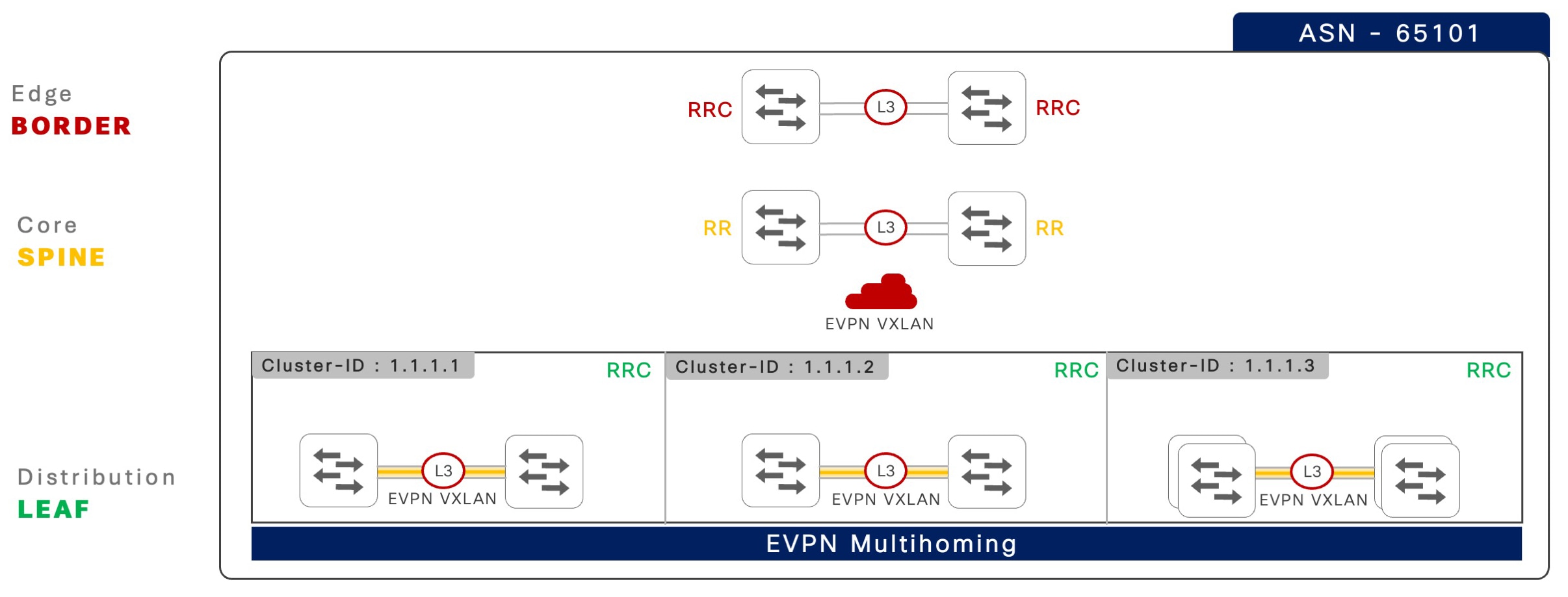
iBGP sessions: Verifies the two-tier hierarchical iBGP sessions between Cisco Catalyst 9000 series switches in EVPN multihoming mode and iBGP peering between a pair of spine switches in operational state.

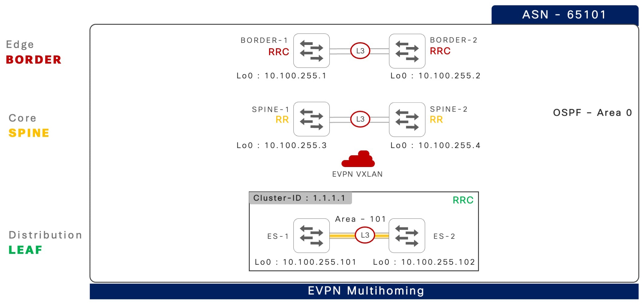
The command output displays iBGP peering between a pair of spine switches, 10.100.255.3 and 10.100.255.4, and direct iBGP peering between ES-1 local 10.100.255.101 and ES-2 10.100.255.102 in EVPN multihoming mode and confirms these iBPG sessions are operational.


ES-1# show bgp l2vpn evpn all summary 

BGP router identifier 10.100.255.101, local AS number 65101 
<snip> 
 
Neighbor         V    AS     MsgRcvd MsgSent   TblVer  InQ  OutQ   Up/Down   State/PfxRcd 
10.100.255.3     4    65101      18    20        104    0     0    00:04:35      2 
10.100.255.4     4    65101      23    25        106    0     0    00:05:19      2 
10.100.255.102   4    65101      51    65        104    0     0    00:04:26      28 
 

Inter-ES Layer 3 EtherChannel: Verifies the operational state of the inter-ES Layer 3 EtherChannels and each of the configured interfaces in bundled state.


ES1# show etherchannel 128 summary  
<snip>  
  
Group    Port-channel     Protocol   Ports  
------+---------------------+---------------+--------------------  
128        Po128(RU)      LACP       Twe1/0/45(P)    Twe1/0/46(P) 


EVPN multihoming core tracking: Verifies the operational state of core tracking Layer 3 interfaces to ensure that all tracked IP reachability paths are operational to maintain iBGP peering with the remote ES system.

This example shows a direct inter-ES EtherChannel and two Layer 3 core network uplink connections configured with core tracking, and all interfaces in a fully operational state.


ES1# show l2vpn evpn multihoming core-tracking   
  
Core Interface           Status           Protocol  
-------------------------------------------------------  
Port-channel128            up               up  
TwentyFiveGigE1/0/47       up               up  
TwentyFiveGigE1/0/48       up               up  
 

Ethernet Segment EtherChannel: Verifies whether the Layer 2 EtherChannel interface is operational with the local ES ports bundled in an EtherChannel group with the LACP protocol.

The output of show etherchannel 1 summary and show l2vpn evpn ethernet-segment commands display two Layer 2 ES EtherChannel interfaces mapped to auto-generated Type-1 ES identifier and implemented automatically in all-active mode.

ES1# show etherchannel 1 summary 
 
<snip>   
Group   Port-channel    Protocol     Ports  
--------+-----------------+--------------+----------
1       Po1(SU)          LACP         Twe1/0/1(P) 
2       Po2(SU)          LACP         Twe1/0/2(P)   
 
ES-1# show l2vpn evpn ethernet-segment  

ESI                        Port   Redundancy Mode    DF Time  SH Label 
----------------------------------------------------------------------- 
0152.5400.0BC2.9700.0100   Po1    all-active         0.001       0        
0152.5400.1599.0300.0100   Po2    all-active         0.001       0 


The output of the show l2vpn evpn ethernet-segment forwarder command displays a pair of ES switches, ES-1 local 10.100.255.101 and ES-2 10.100.255.102, are available to forward data traffic on distributed Layer 2 ES trunk interfaces to the same Layer 2 network devices.

ES-1# show l2vpn evpn ethernet-segment forwarder
 
EVPN Ethernet Segment ID: 0152.5400.0BC2.9700.0100 
  Forwarder List:         10.100.255.101 10.100.255.102  
 
EVPN Ethernet Segment ID: 0152.5400.1599.0300.0100 
  Forwarder List:         10.100.255.101 10.100.255.102 
 

VLAN: The command output shows that a single VLAN ID can be mapped across multiple ES EtherChannel groups stretching the bridge-domain across multiple Layer 2 access switches.
ES-1# show vlan id 2001 
 
VLAN    Name        Status    Ports  
----------------------------------------------------------------- 
2001    VLAN2001    active    Po1, Po2, Po3,…<snip>…, Po40  


Designated forwarder and non-DF roles: Verifies the DF and non-DF roles for each VLAN and EVPN instance (EVI) from both the Cisco Catalyst 9000 series switches paired as a single ES EtherChannel.

The command output displays EVI 2001 mapped to VLAN 2001, the ES-1 switch dynamically elected to block the sending of BUM messages from the local ES EtherChannel; and ES-2 switch is permitted to send BUM messages.

ES-1# show l2vpn evpn evi 2001 detail  
 
EVPN instance:          2001 (VLAN Based)  
<snip>  
    Pseudoports:  
      Port-channel1 service instance 2001 (DF state: PE-to-CE BUM blocked)  
        Routes: 0 MAC, 0 MAC/IP  
        ESI: 0150.06AB.D32E.0000.0100 
 
ES-2# show l2vpn evpn evi 2001 detail  
EVPN instance:          2001 (VLAN Based)  
<snip>  
    Pseudoports:  
      Port-channel1 service instance 2001 (DF state: forwarding)  
        Routes: 0 MAC, 0 MAC/IP  
        ESI: 0150.06AB.D32E.0000.0100  


MAC table: Verifies the locally learned MAC address through the standard data plane from the downstream Layer 2 access network device.

ES-1# show mac address dynamic vlan 2001  

                       Mac Address Table  
----------------------------------------------------- 
Vlan     Mac Address        Type          Ports  
-----------------------------------------------------  
2001    648f.3e42.c142      DYNAMIC       Po2  
2001    5006.abd3.2ec2      DYNAMIC       Po3  
2001    5006.abd2.76c2      DYNAMIC       Po4  


L2VPN: Verifies that each MAC and IP address entry includes the VLAN ID and the remote ES peer switch loopback IP address information learned through the local ES EtherChannel.

For example, on ES-1 switch, the endpoint IP address 10.1.1.1 is only reachable through the remote ES-2 switch. Hence, all data traffic to this host is sent over a Layer 2 VXLAN tunnel from ES-1 to ES-2. However, the remaining hosts are discovered over the local ES EtherChannel, and the MAC and IP addresses are synchronized with the remote ES-2 neighbor. The ES-1 switch prefers local ES EtherChannel interface and upon local path failure it instantly re-routes to the remote ES-2 through the Layer 2 VXLAN tunnel destination loopback address 10.200.255.102.

ES1# show l2vpn evpn mac ip evi 2001 

IP Address    EVI    VLAN     MAC Address      Next Hop(s)  
----------------------------------------------------------------  
10.1.1.1      2001   2001     5006.abd3.2e42   10.200.255.102  
10.1.1.2      2001   2001     648f.3e42.c142   Po2:2001  
                                               10.200.255.102  
10.1.1.3      2001   2001     5006.abd3.2ec2   Po3:2001  
                                               10.200.255.102  
10.1.1.4      2001   2001     5006.abd2.76c2   Po4:2001  
                                               10.200.255.102  


ARP table: Like the standard data plane-based learned local MAC table, the IPv4 ARP or IPv6 ND table represents the ARP and ND entries learned from the local ES EtherChannel. Data plane forwarding to unlisted endpoints reachability is managed through a secondary L2VPN table as shown in the output of the show l2vpn evpn mac ip evi command.


ES1# show ip arp vlan 2001
  
Protocol      Address       Age (min)   Hardware Addr     Type   Interface  
Internet      10.1.1.254         -      0000.5e00.0101    ARPA   Vlan2001  
Internet      10.1.1.2          17      648f.3e42.c142    ARPA   Vlan2001  
Internet      10.1.1.3          13      5006.abd3.2ec2    ARPA   Vlan2001  
Internet      10.1.1.4           4      5006.abd2.e042    ARPA   Vlan2001 
 

Reference configuration for EVPN multihoming in BGP EVPN fabric networks

This section provides EVPN multihoming with iBGP-based hierarchical BGP peering on Cisco Catalyst 9000 series switches.

The reference configurations for Cisco Catalyst 9000 series switches include the fabric device roles of leaf, spine, and border. Additionally, the border-spine device role is also supported.

These configuration examples incorporate various Cisco-validated best practices to support better scale and network resiliency.

iBGP-based network configuration

This section provides step-by-step configuration to implement EVPN multihoming with BGP EVPN fabric in an iBGP-based enterprise campus network. The underlay network built upon dynamic IGP routing protocols, such as OSPF in a multiarea network, is implemented to support large scale fabric networks with resiliency.

The following illustration shows an iBGP-based network design in a multi-tier physical network with divided unique fabric device-roles across each layer.

Figure 3. iBGP-based EVPN multihoming reference fabric network

iBGP-based EVPN multihoming reference fabric network

The following table provides Cisco-validated best practices to build a two-tier hierarchical iBGP peering between two Cisco Catalyst 9000 series switches in EVPN multihoming mode, and iBGP peering to a pair of spine switches.

Table 1. Two-tier hierarchical iBGP peering between a pair of spine switches

Step

Leaf1

Leaf 2

1: Global best practices

!  
system mtu 9100  
!  
port-channel load-balance 
  vlan-src-dst-mixed-ip-port  
ip cef load-sharing algorithm 
   include-ports  
 source destination protocol  
!  
ip tcp mss 8000  
ip tcp window-size 262144  
ip tcp path-mtu-discovery  
! 

!  
system mtu 9100  
!  
port-channel load-balance 
  vlan-src-dst-mixed-ip-port  
ip cef load-sharing algorithm 
   include-ports  
 source destination protocol  
!  
ip tcp mss 8000  
ip tcp window-size 262144  
ip tcp path-mtu-discovery  
! 

2: Inter-ES Layer 3 EtherChannel

! 
interface Port-Channel 128  
 description CONNECTED TO EVPN 
    MH ES SWITCH 
 no switchport  
ip ospf network point-to-point  
 ip ospf multi-area 0  
 ip ospf 100 area 101  
 ip ospf 100 cost 10  
 carrier-delay msec 0  
 hold-queue 4094 in  
 hold-queue 4094 out  
 evpn multihoming core-tracking  
! 

! 
interface Port-Channel 128  
 description CONNECTED TO EVPN 
    MH ES SWITCH 
 no switchport  
ip ospf network point-to-point  
 ip ospf multi-area 0  
 ip ospf 100 area 101  
 ip ospf 100 cost 10  
 carrier-delay msec 0  
 hold-queue 4094 in  
 hold-queue 4094 out  
 evpn multihoming core-tracking  
! 

3: IGP routing and core interfaces

!  
router ospf 100  
 router-id 10.200.255.101  
 max-metric router-lsa include-stub  
  summary-lsa external-lsa on-startup 
      wait-for-bgp   
 nsf cisco   
 fast-reroute per-prefix enable 
    prefix-priority low  
 area 101 stub no-summary  
 passive-interface default  
 no passive-interface Port-Channel 128  
 no passive-interface HundredGig1/0/49  
 no passive-interface HundredGig1/0/50  
!  
interface Loopback 0  
ip ospf 100 area 0  
!  
interface range HundredGig1/0/49-50  
 description CONNECTED TO SPINE DEVICES  
 ip ospf 100 area 0  
 ip ospf network point-to-point  
 carrier-delay msec 0  
 hold-queue 4094 in  
 hold-queue 4094 out  
 evpn multihoming core-tracking  
! 

!  
router ospf 100  
 router-id 10.200.255.102  
 max-metric router-lsa include-stub  
  summary-lsa external-lsa on-startup 
   wait-for-bgp   
 nsf cisco   
 fast-reroute per-prefix enable  
   prefix-priority low  
 area 101 stub no-summary  
 passive-interface default  
 no passive-interface Port-Channel 128  
 no passive-interface HundredGig1/0/49  
 no passive-interface HundredGig1/0/50  
!  
interface Loopback 0  
ip ospf 100 area 0  
!  
interface range HundredGig1/0/49-50  
 description CONNECTED TO SPINE DEVICES  
 ip ospf 100 area 0  
 ip ospf network point-to-point  
 carrier-delay msec 0  
 hold-queue 4094 in  
 hold-queue 4094 out  
 evpn multihoming core-tracking  
! 

4: Inter-ES EVPN MH iBGP peering

!  
router bgp 65101  
 template peer-policy  
  ES-PEER-POLICY  
  send-community both  
 !  
 template peer-session  
   ES-PEER-SESSION-POLICY  
  remote-as 65101  
  description EVPN-MH-DIST-1-PEER 
  update-source Loopback0  
  fall-over host-route  
 !  
 bgp router-id interface Loopback0  
 bgp log-neighbor-changes  
 bgp graceful-restart  
 no bgp default ipv4-unicast 
 neighbor 10.200.255.102 
    inherit peer-session  
  ES-PEER-SESSION-POLICY  
 !  
 address-family l2vpn evpn  
  bgp nexthop trigger critical-delay 0  
  neighbor 10.200.255.102 activate  
  neighbor 10.200.255.102 
     send-community both  
  neighbor 10.200.255.102 inherit 
    peer-policy  
   ES-PEER-POLICY  
 ! 

!  
router bgp 65101  
 template peer-policy  
  ES-PEER-POLICY  
  send-community both  
 !  
 template peer-session  
   ES-PEER-SESSION-POLICY  
  remote-as 65101  
  description EVPN-MH-DIST-1-PEER 
  update-source Loopback0  
  fall-over host-route  
 !  
 bgp router-id interface Loopback0  
 bgp log-neighbor-changes  
 bgp graceful-restart  
 no bgp default ipv4-unicast 
 neighbor 10.200.255.101 inherit 
    peer-session  
  ES-PEER-SESSION-POLICY  
 !  
 address-family l2vpn evpn  
  bgp nexthop trigger critical-delay 0  
  neighbor 10.200.255.101 activate  
  neighbor 10.200.255.101 send-community 
    both  
  neighbor 10.200.255.101 inherit 
     peer-policy  
   ES-PEER-POLICY  
 ! 

5: Fabric iBGP peering

! 
router bgp 65101 
 ! 
 template peer-policy EVPN-SPINE-PEER-POLICY 
  send-community both 
 ! 
 template peer-session 
    EVPN-SPINE-PEER-SESSION-POLICY 
  remote-as 65101 
  description EVPN-SPINE-PEER 
  log-neighbor-changes 
  update-source Loopback0 
  fall-over host-route 
 ! 
 neighbor 10.100.255.3 inherit peer-session 
    EVPN-SPINE-PEER-SESSION-POLICY 
 neighbor 10.100.255.4 inherit peer-session 
    EVPN-SPINE-PEER-SESSION-POLICY 
 ! 
 address-family l2vpn evpn 
  neighbor 10.100.255.3 activate 
  neighbor 10.100.255.3 send-community both 
  neighbor 10.100.255.3 inherit peer-policy 
    EVPN-SPINE-PEER-POLICY 
  neighbor 10.100.255.4 activate 
  neighbor 10.100.255.4 send-community both 
  neighbor 10.100.255.4 inherit peer-policy 
    EVPN-SPINE-PEER-POLICY 
 ! 

! 
router bgp 65101 
 ! 
 template peer-policy 
   EVPN-SPINE-PEER-POLICY 
  send-community both 
 ! 
 template peer-session 
   EVPN-SPINE-PEER-SESSION-POLICY 
  remote-as 65101 
  description EVPN-SPINE-PEER 
  log-neighbor-changes 
  update-source Loopback0 
  fall-over host-route 
 ! 
 neighbor 10.100.255.3 inherit peer-session 
   EVPN-SPINE-PEER-SESSION-POLICY 
 neighbor 10.100.255.4 inherit peer-session
   EVPN-SPINE-PEER-SESSION-POLICY 
 ! 
 address-family l2vpn evpn 
  neighbor 10.100.255.3 activate 
  neighbor 10.100.255.3 send-community both 
  neighbor 10.100.255.3 inherit peer-policy
    EVPN-SPINE-PEER-POLICY 
  neighbor 10.100.255.4 activate 
  neighbor 10.100.255.4 send-community both 
  neighbor 10.100.255.4 inherit peer-policy 
    EVPN-SPINE-PEER-POLICY 
 ! 

The following table provides step-by-step reference configurations, including Cisco validated best practices to configure iBGP peering between a pair of spine and border switches.

Table 2. iBGP peering between a pair of spine and border switches

Step

Spine 1 and Spine 2

Border 1 and Border 2

1: Global best practices

!  
system mtu 9100  
!  
port-channel load-balance 
  vlan-src-dst-mixed-ip-port  
ip cef load-sharing algorithm 
  include-ports  
 source destination protocol  
!  
ip tcp mss 8000  
ip tcp window-size 262144  
ip tcp path-mtu-discovery  
! 

!  
system mtu 9100  
!  
port-channel load-balance 
  vlan-src-dst-mixed-ip-port  
ip cef load-sharing algorithm 
  include-ports  
 source destination protocol  
!  
ip tcp mss 8000  
ip tcp window-size 262144  
ip tcp path-mtu-discovery  
! 

2: IGP routing

Spine-1 
!  
router ospf 100  
 router-id 10.200.255.3  
 max-metric router-lsa include-stub  
  summary-lsa external-lsa on-startup 
   wait-for-bgp   
 nsf cisco   
 fast-reroute per-prefix enable 
   prefix-priority low  
passive-interface default  
 no passive-interface Port-Channel 128  
 no passive-interface HundredGig1/0/49  
 no passive-interface HundredGig1/0/50  
!	 
Spine-2 
!  
router ospf 100  
 router-id 10.200.255.4 
 max-metric router-lsa include-stub  
  summary-lsa external-lsa on-startup 
    wait-for-bgp   
 nsf cisco   
 fast-reroute per-prefix enable 
   prefix-priority low  
passive-interface default  
 no passive-interface Port-Channel 128  
 no passive-interface HundredGig1/0/1 
 no passive-interface HundredGig1/0/2 
 no passive-interface HundredGig1/0/3 
 no passive-interface HundredGig1/0/4  
! 

Border-1 
!  
router ospf 100  
 router-id 10.200.255.1 
 max-metric router-lsa include-stub  
  summary-lsa external-lsa on-startup 
   wait-for-bgp   
 nsf cisco   
 fast-reroute per-prefix enable 
   prefix-priority low  
passive-interface default  
 no passive-interface Port-Channel 128  
 no passive-interface HundredGig1/0/49  
 no passive-interface HundredGig1/0/50  
!	 
Border-2 
!  
router ospf 100  
 router-id 10.200.255.2 
 max-metric router-lsa include-stub  
  summary-lsa external-lsa on-startup 
    wait-for-bgp   
 nsf cisco   
 fast-reroute per-prefix enable 
   prefix-priority low  
passive-interface default  
 no passive-interface Port-Channel 128  
 no passive-interface HundredGig1/0/49  
 no passive-interface HundredGig1/0/50  
! 

3: Core interfaces

!  
interface Loopback 0 
ip ospf 100 area 0  
!  
interface range HundredGig1/0/1-2 
 description CONNECTED TO EVPN MH 
   LEAF DEVICES  
 ip ospf 100 area 0  
 ip ospf network point-to-point  
 carrier-delay msec 0  
 hold-queue 4094 in  
 hold-queue 4094 out  
! 
interface range HundredGig1/0/3-4  
 description CONNECTED TO BORDER DEVICES  
 ip ospf 100 area 0  
 ip ospf network point-to-point  
 carrier-delay msec 0  
 hold-queue 4094 in  
 hold-queue 4094 out  
! 

! 
interface Loopback 0  
ip ospf 100 area 0  
!  
interface range HundredGig1/0/49-50  
 description CONNECTED TO SPINE DEVICES  
 ip ospf 100 area 0  
 ip ospf network point-to-point  
 carrier-delay msec 0  
 hold-queue 4094 in  
 hold-queue 4094 out  
! 

4: Fabric BGP peering

! 
router bgp 65101 
 template peer-policy EVPN-LEAF-PEER-POLICY 
  send-community both 
  route-reflector-client 
 ! 
 template peer-session 
   EVPN-LEAF-BORDER-PEER-SESSION-POLICY 
  remote-as 65101 
  description EVPN-LEAF-PEER 
  log-neighbor-changes 
  update-source Loopback0 
  fall-over host-route 
 ! 
template peer-policy EVPN-BORDER-PEER-POLICY 
  send-community both 
  route-reflector-client 
 ! 
template peer-session 
   EVPN-BORDER-PEER-SESSION-POLICY 
  remote-as 65101 
  description EVPN-BORDER-PEER 
  log-neighbor-changes 
  update-source Loopback0 
  fall-over host-route 
 ! 
 bgp router-id interface Loopback0 
 no bgp client-to-client reflection 
    intra-cluster cluster-id 1.1.1.1 
 bgp log-neighbor-changes 
 bgp graceful-restart 
 no bgp default ipv4-unicast 
 neighbor 10.100.255.1 inherit peer-session 
   EVPN-BORDER-PEER-SESSION-POLICY 
 neighbor 10.100.255.2 inherit peer-session 
   EVPN-BORDER-PEER-SESSION-POLICY 
 neighbor 10.100.255.101 inherit peer-session 
   EVPN-LEAF-PEER-SESSION-POLICY 
 neighbor 10.100.255.101 cluster-id 1.1.1.1 
 neighbor 10.100.255.102 inherit peer-session 
   EVPN-LEAF-PEER-SESSION-POLICY 
 neighbor 10.100.255.102 cluster-id 1.1.1.1 
! 
address-family l2vpn evpn 
  bgp nexthop trigger critical-delay 0 
  neighbor 10.100.255.1 activate 
  neighbor 10.100.255.1 send-community both 
  neighbor 10.100.255.1 inherit peer-policy 
    EVPN-BORDER-PEER-POLICY 
  neighbor 10.100.255.2 activate 
  neighbor 10.100.255.2 send-community both 
  neighbor 10.100.255.2 inherit peer-policy 
    EVPN-BORDER-PEER-POLICY 
  neighbor 10.100.255.101 activate 
  neighbor 10.100.255.101 send-community both 
  neighbor 10.100.255.101 inherit peer-policy 
    EVPN-LEAF-PEER-POLICY 
  neighbor 10.100.255.102 activate 
  neighbor 10.100.255.102 send-community both 
  neighbor 10.100.255.102 inherit peer-policy 
    EVPN-LEAF-PEER-POLICY 
! 

! 
router bgp 65101 
 ! 
 template peer-policy EVPN-SPINE-PEER-POLICY 
  send-community both 
 ! 
 template peer-session 
   EVPN-SPINE-PEER-SESSION-POLICY 
  remote-as 65101 
  description EVPN-SPINE-PEER 
  log-neighbor-changes 
  update-source Loopback0 
  fall-over host-route 
 ! 
 neighbor 10.100.255.3 inherit peer-session 
   EVPN-SPINE-PEER-SESSION-POLICY 
 neighbor 10.100.255.4 inherit peer-session 
   EVPN-SPINE-PEER-SESSION-POLICY 
 ! 
 address-family l2vpn evpn 
  neighbor 10.100.255.3 activate 
  neighbor 10.100.255.3 send-community both 
  neighbor 10.100.255.3 inherit peer-policy 
    EVPN-SPINE-PEER-POLICY 
  neighbor 10.100.255.4 activate 
  neighbor 10.100.255.4 send-community both 
  neighbor 10.100.255.4 inherit peer-policy 
    EVPN-SPINE-PEER-POLICY 
 ! 

EVPN multihoming fabric overlay networks

The successful configuration and establishment of hierarchical iBGP or eBGP fabric peering in an EVPN multihoming deployment is a prerequisite for configuring any overlay network type for segmented data communication.

The Cisco Catalyst 9000 series switches support the following types of overlay networks. Depending on the business and technical requirements, network administrators can consider deploying one or all the following overlay network types on Cisco Catalyst 9000 series switches.