|
Step 1
|
enable
|
Enables privileged EXEC mode.
|
|
Step 2
|
configure terminal
Device# configure terminal
|
Enters global configuration mode.
|
|
Step 3
|
l2vpn evpn
Device(config)# l2vpn evpn
|
Enables L2VPN EVPN capability and enters EVPN configuration mode.
|
|
Step 4
|
anycast gateway mac auto
Device(config-evpn)# anycast gateway mac auto
|
Enables load sharing and redundancy with the auto-derived common logical IP gateway MAC address (00:00:5e:00:01:01) on all
SVI interfaces between both the ES systems.
|
|
Step 5
|
replication-type ingress
Device(config-evpn) #replication-type ingress
|
Enables unicast mode BUM replication to extend Layer 2 broadcast between two ES systems.
|
|
Step 6
|
router id id
Device(config-evpn)# router id loopback0
|
(Optional) Configures the L2VPN router ID on a loopback interface.
|
|
Step 7
|
multihoming peering adjacent
Device(config-evpn)# multihoming peering adjacent
|
Configures direct iBGP-to-EVPN peering support for non-fabric networks.
|
|
Step 8
|
multihoming aliasing disable
Device(config-evpn)# multihoming aliasing disable
|
Disables auto generation and advertising of per-EVI EVPN route types.
|
|
Step 9
|
multicast advertise sync-only
Device(config-evpn)# multicast advertise sync-only
|
Enables IGMP join and leaf state synchronization and maintains consistent multicast group and receiver states between two
ES systems in non-fabric networks.
|
|
Step 10
|
exit
Device(config-evpn)# exit
|
Exits EVPN configuration mode and returns to global configuration mode.
|
|
Step 11
|
l2vpn evpn instance instance-number vlan-based
Device(config)# l2vpn evpn instance 2002 vlan-based
|
Configures an L2VPN EVPN virtual instance with a unique ID.
|
|
Step 12
|
encapsulation vxlan
Device(config-evpn-evi)# encapsulation vxlan
|
Enables VXLAN encapsulation to bridge inter-ES data between two systems.
|
|
Step 13
|
exit
Device(config-evpn-evi)# exit
|
Exits EVPN-instance configuration mode and returns to global configuration mode.
|
|
Step 14
|
vlan id
Device(config)# vlan 2002
|
Configures a VLAN ID in a local switch database.
|
|
Step 15
|
vlan configuration id
Device(config)# vlan configuration 2002
|
Configures EVI for the edge VLAN and enters VLAN configuration mode.
|
|
Step 16
|
member evpn-instance instance-id vni l2vni-id
Device(config-vlan-config)# member evpn-instance 2002 vni 102002
|
Binds an L2VPN EVPN instance with the VLAN ID and assigns a unique VXLAN ID for the selected VLAN.
|
|
Step 17
|
exit
Device(config-vlan-config)# exit
|
Exits VLAN configuration mode and returns to global configuration mode.
|
|
Step 18
|
interface nve id
Device(config)# interface nve 1
|
Configures a virtual NVE interface binding one or more EVIs to enable the system-wide VXLAN forwarding function.
|
|
Step 19
|
source interface interface-id
Device(config-if)# source interface Loopback0
|
Configures a Loopback interface as the source interface to enable Layer 2 data communication over a VXLAN tunnel.
|
|
Step 20
|
host-reachability protocol bgp
Device(config-if)# host-reachability protocol bgp
|
Configures BGP as the host-reachability control-plane protocol on this interface.
|
|
Step 21
|
member vni l2vni-id ingress-replication
Device(config-if)# member vni 102002 ingress-replication
|
Binds the Layer 2 VNI ID in ingress-replication mode.
|
|
Step 22
|
l2vpn evpn ethernet-segment id
Device(config-if)# l2vpn evpn ethernet-segment 1
|
Configures the static Ethernet segment ID to be assigned to the Layer 2 ES physical port and enters Layer 2 VPN EVPN ethernet
segment configuration mode.
|
|
Step 23
|
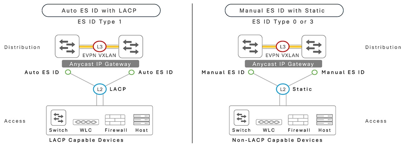
identifier type 0 H.H.H.H.H.H.H.H.H
- identifier type 0 H.H.H.H.H.H.H.H.H
- identifier type 3 system-mac H.H.H
Device(config-evpn-es)# identifier type 0 01.01.01.01.01.01.01.01.01
Device(config-evpn-es)# identifier type 3 a.b.c
|
Configure Type 0 or Type 3 manual ES ID.
|
|
Step 24
|
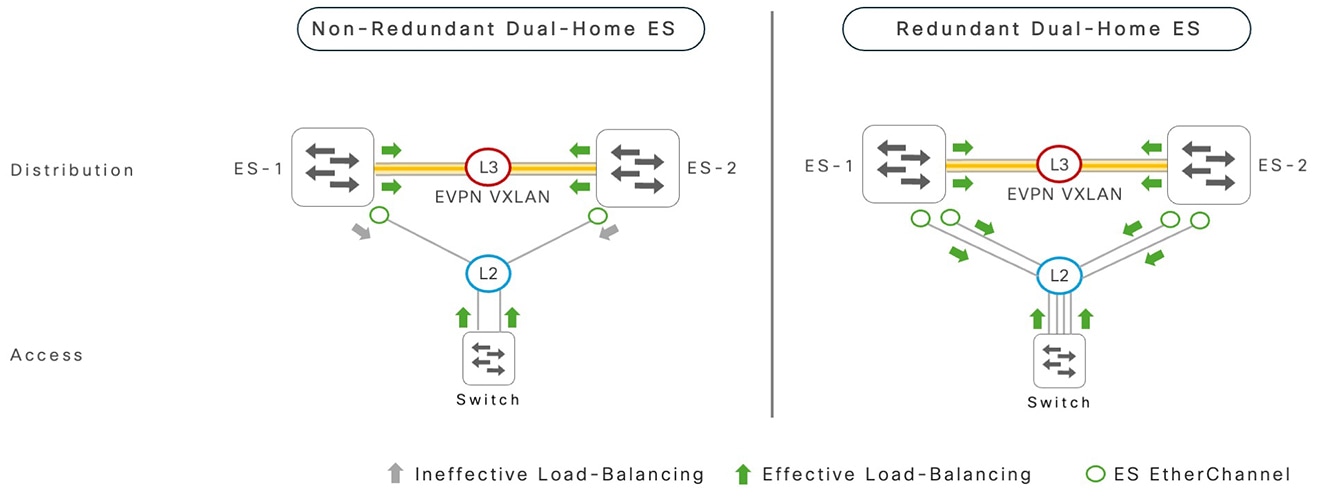
redundancy mode all-active
Device(config-evpn-es)# redundancy mode all-active
|
Configure EVPN multihoming redundancy mode as all-active.
|
|
Step 25
|
exit
Device(config-evpn-es)# exit
|
Exits Layer 2 VPN EVPN ethernet segment configuration mode and returns to global configuration mode.
|
|
Step 26
|
interface port-channel id
Device(config)# interface port-channel 1
|
Configures a Layer 2 ES EtherChannel interface and enters interface configuration mode.
|
|
Step 27
|
switchport trunk allowed vlan vlan-id
Device(config-if)# switchport trunk allowed vlan 2002
|
Enables L2VPN data VLAN on a Layer 2 ES EtherChannel trunk port.
|
|
Step 28
|
evpn ethernet-segment id
Device(config-if)# evpn ethernet-segment 1
|
Enables an ES with automatic LACP system ID on an EtherChannel.
|
|
Step 29
|
end
|
Exits interface configuration mode and returns to privileged EXEC mode.
|

 Feedback