Connector and Cable Specifications
This chapter describes the connector and cable specifications.
Connector Specifications
- 10/100/1000 Ports
- 100M/1G/2.5G/5G/10G Ports
- 10-Gigabit Ethernet CX1 (SFP+ Copper) Connectors
- SFP and SFP+ Modules
- 10/100/1000 Ethernet Management Port
- Console Port
10/100/1000 Ports
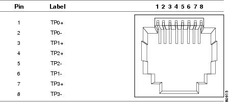
The 10/100/1000 Ethernet ports on switches use RJ-45 connectors and Ethernet pinouts.
Figure 2-1 10/100/1000 Port Pinouts
100M/1G/2.5G/5G/10G Ports
The 100M/1G/2.5G/5G/10G multi-Gigabit Ethernet ports on switches use RJ-45 connectors and Ethernet pinouts.
Figure 2-2 100M/1G/2.5G/5G/10G Port Pinouts
10-Gigabit Ethernet CX1 (SFP+ Copper) Connectors
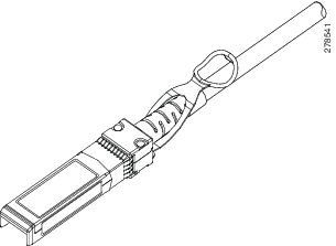
The 10-Gigabit Ethernet electrical modules use CX1 copper connectors similar to the one shown in Figure 2-3.

Note![]() When ordering or using CX1 cables, ensure that the version identifier is 2 or higher.
When ordering or using CX1 cables, ensure that the version identifier is 2 or higher.
The 10-Gigabit Ethernet optical modules use the connectors shown in Figure 2-4 and Figure 2-5.
Figure 2-3 10-Gigabit Ethernet CX1 Copper Connector
SFP and SFP+ Modules
Figure 2-4, Figure 2-5, and Figure 2-6 show the SFP module connectors.
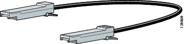
The switch supports the SFP module patch cable, a 0.5-meter, copper, passive cable with SFP module connectors at each end (Figure 2-7). This cable can be used (only with 1-Gigabit Ethernet SFP ports) to connect two Catalyst 3650 switches in a cascaded configuration.
Figure 2-4 Duplex LC Cable Connector
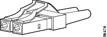
Figure 2-5 Simplex LC Cable Connector
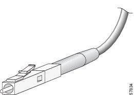
Figure 2-6 Copper SFP Module RJ-45 Connector
Figure 2-7 SFP Module Patch Cable
10/100/1000 Ethernet Management Port
The 10/100/1000 Ethernet management port uses RJ-45 connectors with Ethernet pinouts. Figure 2-8 shows the pinouts.
Figure 2-8 10/100/1000 Port Pinouts
Console Port
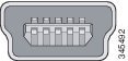
The switch has two console ports: a USB 5-pin mini-Type B port on the front panel (see Figure 2-9) and an RJ-45 console port on the rear panel.
Figure 2-9 USB Mini-Type B Port
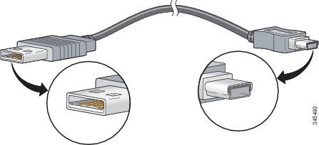
The USB console port uses a USB Type A to 5-pin mini-Type B cable, shown in Figure 2-10. The USB Type A-to-USB mini-Type B cable is not supplied. You can order an accessory kit (part number 800-33434) that contains this cable.
Figure 2-10 USB Type A-to-USB 5-Pin Mini-Type B Cable
The RJ-45 console port uses an 8-pin RJ-45 connector (See Table 2-2 and Table 2-3 .) The supplied RJ-45-to-DB-9 adapter cable is used to connect the console port of the switch to a console PC. Provide an RJ-45-to-DB-25 female DTE adapter if you want to connect the switch console port to a terminal. You can order a kit (part number ACS-DSBUASYN=) containing that adapter. For console port and adapter pinout information, see Table 2-2 and Table 2-3 .
Cable and Adapter Specifications
- StackWise Cables
- StackWise Adapters
- StackWise Adapter Blanks
- SFP and SFP+ Module Cable Specifications
- Four Twisted-Pair Cable Pinouts
- Two Twisted-Pair Cable Pinouts
- Identifying a Crossover Cable
- Console Port Adapter Pinouts
StackWise Cables
Figure 2-11 shows a StackWise stacking cable.
Figure 2-11 StackWise Stacking Cable
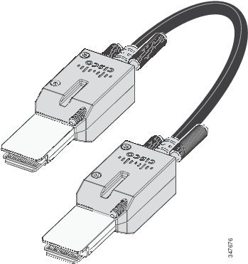
You can order these StackWise cables (nonhalogen) from your Cisco sales representative:
StackWise Cables Minimum Bend Radius and Coiled Diameter
Table 2-1 specifies the minimum bend radius and coiled diameter for each StackWise cable.
|
|
|
|
|
|---|---|---|---|
StackWise Adapters
A StackWise adapter must be installed in the stacking port to enable stacking. The StackWise cable connects to the StackWise adapter in the stacking port. For switches ordered with stacking, the StackWise adapters are preinstalled.
If the switches are not ordered with stacking, the adapters must be ordered separately and installed. You can order a StackWise adapter as part of a StackWise stacking upgrade kit (part number C3650-STACK-KIT=) that contains two adapters and a 0.5-m StackWise cable.
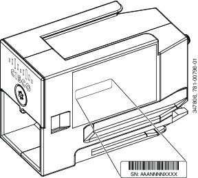
Locating the StackWise Adapter Serial Number
If you contact Cisco Technical Assistance regarding a StackWise adapter, you should know the serial number. See Figure 2-12 to find out about how to locate the serial number.
Figure 2-12 Location of the Serial Number on the StackWise Adapter
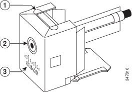
StackWise Adapter Blanks
A StackWise adapter blank is installed in the stacking port if stacking is not specified at the time of ordering the switch. The StackWise adapter blank is screwed into the stacking port and must be removed and replaced by a StackWise adapter if the port is to be used for stacking. StackWise Adapter Blank shows a StackWise adapter blank.
Figure 2-13 StackWise Adapter Blank
|
|
|
||
|
|
|
SFP and SFP+ Module Cable Specifications
Each port must match the wave-length specifications on each end of the cable, and the cable must not exceed the stipulated cable length. Copper 1000BASE-T SFP module transceivers use standard four twisted-pair, Category 5 cable at lengths up to 328 feet (100 meters).
For cabling specifications, refer to the Cisco Transceiver Modules data sheet at:
http://www.cisco.com/en/US/products/hw/modules/ps5455/products_data_sheets_list.html
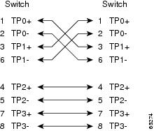
Four Twisted-Pair Cable Pinouts
Figure 2-14 Four Twisted-Pair Straight-Through Cable Schematic
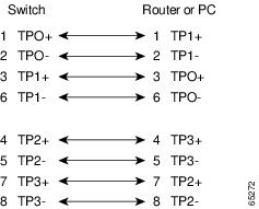
Figure 2-15 Four Twisted-Pair Crossover Cable Schematic
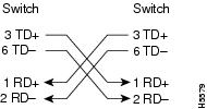
Two Twisted-Pair Cable Pinouts
Figure 2-16 Two Twisted-Pair Straight-Through Cable Schematic
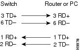
Figure 2-17 Two Twisted-Pair Crossover Cable Schematic
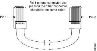
Identifying a Crossover Cable
To identify a crossover cable, hold the cable ends side-by-side, with the tab at the back. The wire connected to the pin on the outside of the left plug should be the same color as the wire connected to the pin on the outside of the right plug. (See Figure 2-18.)
Figure 2-18 Identifying a Crossover Cable
Console Port Adapter Pinouts
The console port uses an 8-pin RJ-45 connector, which is described in Table 2-2 and Table 2-3 . If you did not order a console cable, you should provide an RJ-45-to-DB-9 adapter cable to connect the switch console port to a PC console port. You should provide an RF-45-to-DB-25 female DTE adapter if you want to connect the switch console port to a terminal. You can order a kit with an adapter (part number ACS-DSBUASYN=). For console port and adapter pinout information, see Table 2-2 and Table 2-3 .
Table 2-2 lists the pinouts for the console port, the RF-45-to-DB-9 adapter cable, and the console device.
|
Port (DTE) |
Terminal Adapter |
Device |
|---|---|---|
|
|
|
|
Table 2-3 lists the pinouts for the console port, RJ-45-to-DB-25 female DTE adapter, and the console device.
Note![]() The RJ-45-to-DB-25 female DTE adapter is not supplied with the switch. You can order a kit with the adapter (part number ACS-DSBUASYN=) from Cisco.
The RJ-45-to-DB-25 female DTE adapter is not supplied with the switch. You can order a kit with the adapter (part number ACS-DSBUASYN=) from Cisco.
|
Port (DTE) |
Terminal A dapter |
Device |
|---|---|---|
|
|
|
|
 Feedback