Installing the Fan
This chapter describes how to install a fan module. The following topics are included in this chapter:

Note![]() The contents of this chapter are not applicable to the Cisco Catalyst 3650-24PDM and Catalyst 3650-48FQM switches. These switches come with fixed fan modules and require no separate installation.
The contents of this chapter are not applicable to the Cisco Catalyst 3650-24PDM and Catalyst 3650-48FQM switches. These switches come with fixed fan modules and require no separate installation.
Overview of the Fan Modules
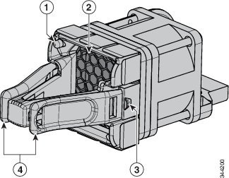
The switch has three fan modules. Fan modules are hot-swappable. A powered switch should always have more than one operational fan. The switch can operate with two operational fans and one nonfunctional fan, but the failed fan should be replaced as soon as possible to avoid a service interruption due to a second fan fault.
Note![]() Three fans are required for proper cooling.
Three fans are required for proper cooling.
|
|
|
||
|
|
|
Fan Module Installation
Installation Guidelines

Warning![]() Only trained and qualified personnel should be allowed to install, replace, or service this equipment. Statement 1030
Only trained and qualified personnel should be allowed to install, replace, or service this equipment. Statement 1030
Note![]() Fans should be removed or installed only when StackWise adapters or StackWise adapter blanks are installed in each port.
Fans should be removed or installed only when StackWise adapters or StackWise adapter blanks are installed in each port.
Observe these guidelines when removing or installing a fan module:
- Do not force a fan module into a slot. This might damage the pins on the switch if they are not aligned with the module.
- A fan module that is only partially connected might disrupt the system operation.
- The switch supports hot swapping of the fan module. You can remove and replace the module without interrupting normal switch operation.
Installing a Fan Module
Step 1![]() Pinch the fan module release handle, and slide the module out.
Pinch the fan module release handle, and slide the module out.

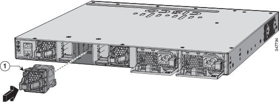
Step 2![]() Install the fan module in the fan slot, and firmly push it into the slot, applying pressure to the end of the module, not the extraction handles. When correctly inserted, the fan module is flush with the switch rear panel. When the fan is operating, a green LED is on in the top left corner of the fan. See Figure 3-2.
Install the fan module in the fan slot, and firmly push it into the slot, applying pressure to the end of the module, not the extraction handles. When correctly inserted, the fan module is flush with the switch rear panel. When the fan is operating, a green LED is on in the top left corner of the fan. See Figure 3-2.
Warning![]() Do not reach into a vacant slot when installing or removing a module. Exposed circuitry is an energy hazard. Statement 206
Do not reach into a vacant slot when installing or removing a module. Exposed circuitry is an energy hazard. Statement 206
Figure 3-2 Installing the Fan Module
|
|
Finding the Fan Module Serial Number
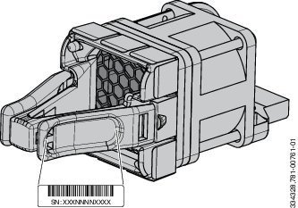
If you contact Cisco Technical Assistance regarding a fan module, you should know the fan module serial number. See Figure 3-3 for the serial number location.
Figure 3-3 Fan Module Serial Number
 Feedback