The documentation set for this product strives to use bias-free language. For the purposes of this documentation set, bias-free is defined as language that does not imply discrimination based on age, disability, gender, racial identity, ethnic identity, sexual orientation, socioeconomic status, and intersectionality. Exceptions may be present in the documentation due to language that is hardcoded in the user interfaces of the product software, language used based on RFP documentation, or language that is used by a referenced third-party product. Learn more about how Cisco is using Inclusive Language.
MPLS Label Distribution Protocol (LDP) enables peer label switch routers (LSRs) in an Multiprotocol Label Switching (MPLS)
network to exchange label binding information for supporting hop-by-hop forwarding in an MPLS network. This module explains
the concepts related to MPLS LDP and describes how to configure MPLS LDP in a network.
Feature history for MPLS Label Distribution Protocol
This table provides release and platform support information for the features explained in this module.
These features are available in all the releases subsequent to the one they were introduced in, unless noted otherwise.
Release
Feature name and description
Supported platform
Cisco IOS XE 26.2.1ea
MPLS Label Distribution Protocol feature support has been introduced.
Cisco C9550 Series Smart Switches
Cisco IOS XE 17.18.2
MPLS Label Distribution Protocol
Cisco C9350 Series Smart Switches
Cisco C9610 Series Smart Switches
MPLS Label Distribution Protocol
Multiprotocol Label Switching (MPLS) Label Distribution Protocol (LDP) is a signaling protocol that
enables label switch routers (LSRs) in an MPLS network to discover potential peers and establish sessions with them to exchange
label binding information
provides the means for LSRs to request, distribute, and release label prefix binding information to peer devices, and
supports hop-by-hop forwarding in an MPLS network.
Hop-by-hop forwarding: MPLS LDP allows one LSR to inform another LSR of the label bindings it has made. Once a pair of devices
communicate the LDP parameters, they establish a label switched path (LSP). MPLS LDP distributes labels along normally routed
paths to support MPLS forwarding, a method also known as hop-by-hop forwarding. MPLS LDP is useful for applications that require
hop-by-hop forwarding, such as MPLS VPNs.
IP forwarding: When a packet arrives at a device, the device looks at the destination address in the IP header, performs a
route lookup, and forwards the packet to the next hop.
MPLS forwarding: When a packet arrives at a device, the device looks at the incoming label, looks up the label in a table,
and then forwards the packet to the next hop.
LDP sessions
LDP sessions are communication channels that
label switch routers (LSRs) establish to exchange label binding information
are initiated when LSRs send out messages to discover other LSRs, and
can be directly connected or nondirectly connected.
Types of LDP sessions
There are two types of LDP sessions:
Directly connected LDP sessions: that are established between LSRs that are one hop from each other, using link Hello messages
to discover neighbors and negotiate session parameters for label exchange
Indirectly connected LDP sessions: that are established between LSRs that are more than one hop apart, using targeted Hello
messages for extended discovery. They enable label distribution for applications like MPLS Traffic Engineering (TE) tunnels.
Basic elements of an LDP session
This topic describes the basic elements of an LDP session—LDP label bindings, LDP label spaces, and LDP identifiers.
LDP label bindings
An LDP label binding is an association between a destination prefix and a label.
LDP label spaces
A set of possible labels from which a label used in a label binding is allocated from is called a label space.
LDP supports two types of label spaces:
Interface-specific: An interface-specific label space uses interface resources for labels. For example, label-controlled ATM
(LC-ATM) interfaces use virtual path identifiers (VPIs) or virtual circuit identifiers (VCIs) for labels. Depending on its
configuration, an LDP platform may support zero, one, or more interface-specific label spaces.
Platform-wide: An LDP platform supports a single platform-wide label space for use by interfaces that can share the same labels.
For Cisco platforms, all interface types, except LC-ATM, use the platform-wide label space.
LDP identifier
LDP uses a 6-byte quantity called an LDP identifier (LDP ID) to name label spaces. The LDP ID is made up of these components:
LPD router ID: the first four bytes that identify the label switch router (LSR) that owns the label space.
Local label space ID: The last two bytes that identify the label space within the LSR. For the platform-wide label space,
the last two bytes of the LDP ID are always both 0.
The LDP ID takes this form: LDP router ID : local label space ID. Examples: 172.16.0.0:0, 192.168.0.0:3
The mpls ldp router-id command allows you to specify the IP address of an interface as the LDP router ID.
The device determines the LDP router ID as follows, if the mpls ldp router-id command is not executed:
The device examines the IP addresses of all operational interfaces.
If these IP addresses include loopback interface addresses, the device selects the largest loopback address as the LDP router
ID.
Otherwise, the device selects the largest IP address pertaining to an operational interface as the LDP router ID.
The normal or default method for determining the LDP router ID may result in a router ID that is not usable in certain situations.
For example, the device might select an IP address as the LDP router ID that the routing protocol cannot advertise to a neighboring
device.
Restriction for MPLS LDP sessions
You cannot enable MPLS LDP on a Virtual Routing and Forwarding (VRF) interface.
How directly connected LDP sessions work
Summary
The key components involved in the process are:
Label Switch Router (LSR): sends and receives LDP Hello messages, establishes TCP connections, and negotiates session parameters
LDP link Hello messages: User Datagram Protocol (UDP) packets sent through multicast to all devices on a subnet for basic
discovery
Workflow
These stages describe how LSRs discover each other and establish LDP sessions for label exchange:
Discovery: An LSR sends LDP link Hello messages (UDP multicast) to all devices on its subnet.
Response: A neighboring LSR responds to the link Hello message, allowing the two devices to begin establishing an LDP session.
Role determination: Devices compare their transport addresses; the device with the higher IP address takes the active role,
establishing the LDP TCP connection.
Session negotiation: After the TCP connection is established, LSRs negotiate session parameters, including the label distribution
method.
Label distribution : LSRs exchange label binding information using either
Downstream unsolicited : where an LSR advertises label mappings to peers without being asked, or
Downstream on demand : where an LSR advertises label mappings to a peer only when the peer requests them.
Result
A directly connected LDP session is established, enabling the exchange of label binding information between neighboring LSRs.
How indirectly connected LDP sessions work
Summary
These are the key components and commands involved in establishing indirectly connected LDP sessions:
Label Switch Router (LSR): sends and receives targeted LDP Hello messages, establishes TCP connections, and exchanges label
binding information
Targeted Hello messages: UDP unicast messages specifically addressed to a remote LSR for extended discovery
mpls ldp neighbor targeted command: allows setting up targeted sessions when other means like, TE tunnels or AToM VCs do not apply, or to improve label
convergence time for directly connected neighbors when links are unstable
mpls ldp discovery targeted-hello accept command: configures an LSR to respond to requests for targeted Hello messages, allowing it to act as a passive participant
Workflow
These stages describe how indirectly connected LDP sessions are established and maintained:
Extended Discovery: An LSR sends a targeted Hello message, UDP unicast, specifically addressed to an indirectly connected
neighbor.
Response: The indirectly connected LSR responds to the targeted Hello message, initiating the establishment of an LDP session.
Session establishment: A Multiprotocol Label Switching (MPLS) LDP targeted session, which is a label distribution session,
is established between the devices.
Role assignment: The exchange of targeted Hello messages can involve different roles:
Active/Passive: Device 1 sends a targeted Hello with a response request; device 2 responds if configured to do so (passive).
Both Active: Both device 1 and device 2 send targeted Hello messages to each other.
Protocol mandate: The active LSR dictates the protocol for the targeted session, and the passive LSR adopts the protocol of
the received targeted Hello messages
Convergence improvement (Optional): The mpls ldp neighbor ip-address targeted command can maintain sessions through alternate routes if direct links fail, allowing LSRs to retain and quickly reinstall
labels.
Result
An indirectly connected LDP session is established, enabling label distribution between distant LSRs, which is crucial for
applications like MPLS Traffic Engineering tunnels.
Configure MPLS LDP sessions
Establish directly connected MPLS LDP sessions
Use this procedure to establish MPLS LDP sessions between two directly connected devices.
This task involves enabling MPLS hop-by-hop forwarding globally and on specific interfaces, then configuring LDP as the label
protocol for all interfaces.
Before you begin
Enable Cisco Express Forwarding on the device.
Procedure
Step 1
Configure MPLS hop-by-hop forwarding globally.
Example:
Device> enable
Device# configure terminal
Device(config)# mpls ip
The mpls ip command is enabled by default. You do not have to specify this command.
Globally enabling MPLS forwarding does not enable it on the device interfaces. You must enable MPLS forwarding on the interfaces
as well as for the device.
Step 2
Configure LDP as the label protocol for all interfaces.
Example:
Device(config)# mpls label protocol ldp
The options available for this command depends on the hardware platform.
You can override this global setting for specific interfaces by specifying the command in interface configuration mode with
either the tdp or both keyword.
Step 3
Configure MPLS hop-by-hop forwarding on a specific interface by entering the interface configuration mode.
Example:
Device(config)# interface HundredGigE 0/3/0
Device(config-if)# mpls ip
Device(config-if)# end
You must enable MPLS forwarding on the interfaces as well as for the device.
Step 4
Verify that directly connected MPLS LDP sessions are established, allowing label distribution between adjacent devices.
Verify that the interfaces have been configured to use LDP.
Example:
Device# show mpls interfaces
Interface                  IP            Tunnel   BGP Static Operational
HundredGigE0/3/0           Yes (ldp)     No       No  No     Yes
HundredGigE0/3/1           Yes           No       No  No     Yes
Verify that the interface is up and is sending Discovery Hello messages, as opposed to TDP Hello messages.
Example:
Device# show mpls ldp discovery
Local LDP Identifier:
    172.16.12.1:0
    Discovery Sources:
    Interfaces:
        HundredGigE0/3/0 (ldp): xmit
Display the status of LDP sessions.
Example:
Device# show mpls ldp neighbor
Peer LDP Ident: 10.1.1.2:0; Local LDP Ident 10.1.1.1:0
TCP connection: 10.1.1.2.18 - 10.1.1.1.66
State: Oper; Msgs sent/rcvd: 12/11; Downstream
Up time: 00:00:10
LDP discovery sources:
HundredGigE0/1/0, Src IP addr: 10.20.10.2
Addresses bound to peer LDP Ident:
10.1.1.2    10.20.20.1    10.20.10.2
Establish indirectly connected LDP sessions
Follow this procedure to establish MPLS LDP sessions between devices that are not directly connected.
This task involves enabling MPLS hop-by-hop forwarding globally and on specific interfaces, then configuring LDP as the label
protocol for all interfaces.
This task explains how to configure indirectly connected MPLS LDP sessions, typically over a tunnel interface, to enable label
distribution between distant Label Switch Routers (LSRs).
Before you begin
Enable Cisco Express Forwarding (CEF) on the device.
Configure the devices at both ends of the tunnel to be active or enable one device to be passive with the mpls ldp discovery targeted-hello accept command.
Procedure
Step 1
Configure MPLS hop-by-hop forwarding globally.
Example:
Device> enable
Device# configure terminal
Device(config)# mpls ip
The mpls ip command is enabled by default. You do not have to specify this command.
Globally enabling MPLS forwarding does not enable it on the device interfaces. You must enable MPLS forwarding on the interfaces
as well as for the device.
Step 2
Configure LDP as the label protocol for all interfaces.
Example:
Device(config)# mpls label protocol ldp
The options available for this command depends on the hardware platform.
You can override this global setting for specific interfaces by specifying the command in interface configuration mode with
either the tdp or both keyword.
Step 3
Configure a tunnel interface and assign an IP address to the interface.
The LSR 172.16.0.0 sent LDP link Hello messages on interface POS1/2/0 and discovered neighbor 172.31.255.255.
The local LSR sent LDP targeted Hello messages associated with interface Tunnel1 to target 192.168.255.255. The LSR was configured
to use LDP.
The local LSR is active for targeted discovery activity with 192.168.255.255; this means that the targeted Hello messages
it sends to 192.168.255.255 carry a response request. The local LSR was configured to have an LDP session with the nondirectly
connected LSR 192.168.255.255.
The local LSR is not passive from the discovery activity with 192.168.255.255 for one of these reasons:
The targeted Hello messages it receives from 192.168.255.255 do not carry a response request.
The local LSR has not been configured to respond to such requests.
The local LSR sent Tag Distribution Protocol (TDP) directed Hello messages to the target LSR 192.168.0.0. This LSR uses TDP
because the Hello messages received from the target LSR 192.168.0.0 were TDP directed Hello messages.
The local LSR is passive in discovery activity with LSR 192.168.0.0. This means that the directed Hello messages it receives
from LSR 192.168.0.0 carry a response request and that the local LSR has been configured with the mpls ldp discovery targeted-hello accept command to respond to such requests from LSR 192.168.0.0.
The local LSR is not active in discovery activity with LSR 192.168.0.0, because no application that requires an LDP session
with LSR 192.168.0.0 has been configured on the local LSR.
Preserve QoS settings of MPLS LDP packets
Use this procedure to preserve QoS settings of MPLS LDP packets in an LDP session.
Normally, LDP advertises an Implicit NULL label for directly connected routes, causing the penultimate LSR to remove the MPLS
header. This removal can lead to the loss of QoS values before the packet reaches the last LSR. By advertising an Explicit
NULL label, the LSR at the penultimate hop forwards MPLS packets with a NULL label (value of zero) instead of forwarding them
as IP packets, thereby preserving the QoS information.
When you issue the mpls ldp explicit-null command, Explicit NULL is advertised in place of Implicit NULL for directly connected prefixes.
Note
An explicit NULL label is not needed when the penultimate hop receives MPLS packets with a label stack that contains at least
two labels and penultimate hop popping is performed. In that case, the inner label can still carry the QoS value needed by
the penultimate and edge LSR to implement their QoS policy.
Procedure
Step 1
Establish directly connected MPLS LDP session on the switch by configuring MPLS hop-by-hop forwarding globally and at the
interface-level. Also, configure the use of LDP on all interfaces.
Example:
Device> enable
Device# configure terminal
Device(config)# mpls ip
Device(config)# mpls label protocol ldp
Device(config-mpls)# exit
Device(config)# interface HundredGigE 0/3/0
Device(config-if)# mpls ip
Device(config-if)# end
Step 2
Configure the switch to advertise an Explicit Null label in situations where it would normally advertise an Implicit Null
label.
Use mpls ldp explicit-null command without any keywords.
Device(config)# mpls ldp explicit-null
Enabling Explicit NULL on an egress LSR causes that LSR to advertise the Explicit NULL label to all adjacent MPLS devices.
Use mpls ldp explicit-null command with for keyword.
Enabling Explicit NULL with the for keyword with a standard access control list (ACL) changes all tables in the adjacent MPLS devices to swap an Explicit NULL
label for only those entries specified in the access-list. In this example, an access-list is created that contains the 10.24.24.24/32
entry. Explicit NULL is configured for that access list.
Use mpls ldp explicit-null command with to keyword.
Enabling Explicit NULL with the to keyword and an access list enables you to advertise Explicit NULL labels to only those adjacent devices specified in the
access-list. To advertise Explicit NULL to a particular device, you must specify the LDP ID of the device in the access-list.
In this example, an access-list contains the 10.15.15.15/32 entry, which is the LDP ID of an adjacent MPLS device. The device
that is configured with Explicit NULL advertises Explicit NULL labels only to that adjacent device.
Use mpls ldp explicit-null command with both for and to keywords.
Device(config)# mpls ldp explicit-null for 24 to 15
Enabling Explicit NULL with both the for and to keywords allows you to specify which routes to advertise with Explicit NULL labels and to which adjacent devices to advertise
these Explicit NULL labels.
Step 3
Verify that MPLS packets are forwarded with an Explicit NULL label, that is, value of zero.
Example:
Scenario 1: Explicit NULL configuration without any keyword
Device# show mpls forwarding-table

Local  Outgoing    Prefix            Bytes label Outgoing           Next Hop
label  label or VC or Tunnel Id      switched   interface
19     Pop tag     10.12.12.12/32    0          HundredGigE2/1/0    172.16.0.1
22     0           10.14.14.14/32    0          HundredGigE2/0/0    192.168.0.2
23     0           172.24.24.24/32   0          HundredGigE2/0/0    192.168.0.2
24     0           192.168.0.0/8     0          HundredGigE2/0/0    192.168.0.2
25     0           10.15.15.15/32    0          HundredGigE2/0/0    192.168.0.2
26     0           172.16.0.0/8      0          HundredGigE2/0/0    192.168.0.2
27     25          10.16.16.16/32    0          HundredGigE2/0/0    192.168.0.22
28     0           10.34.34.34/32    0          HundredGigE2/0/0    192.168.0.2
If you issue the show mpls forwarding-table command on an adjacent device, the output shows that the only the outgoing labels for the addresses specified (172.24.24.24/32)
change from Pop label to 0. All other Pop label outgoing labels remain the same.
Scenario 2: Explicit NULL configuration with for keyword
Device# show mpls forwarding-table

Local  Outgoing    Prefix            Bytes label Outgoing           Next Hop
label  label or VC or Tunnel Id      switched   interface
19     Pop tag     10.12.12.12/32    0          HundredGigE2/1/0    172.16.0.1
22     0           10.14.14.14/32    0          HundredGigE2/0/0    192.168.0.2
23     0           172.24.24.24/32   0          HundredGigE2/0/0    192.168.0.2
24     0           192.168.0.0/8     0          HundredGigE2/0/0    192.168.0.2
25     0           10.15.15.15/32    0          HundredGigE2/0/0    192.168.0.2
26     0           172.16.0.0/8      0          HundredGigE2/0/0    192.168.0.2
27     25          10.16.16.16/32    0          HundredGigE2/0/0    192.168.0.22
28     0           10.34.34.34/32    0          HundredGigE2/0/0    192.168.0.2
Scenario 3: Explicit NULL configuration with to keyword
Device# show mpls forwarding-table

Local  Outgoing    Prefix            Bytes label Outgoing          Next Hop
label  label or VC or Tunnel Id      switched   interface
19     Pop tag     10.12.12.12/32    0          HundredGigE2/1/0    172.16.0.1
22     0           10.14.14.14/32    0          HundredGigE2/0/0    192.168.0.2
23     0           172.24.24.24/32   0          HundredGigE2/0/0    192.168.0.2
24     0           192.168.0.0/8     0          HundredGigE2/0/0    192.168.0.2
25     0           10.15.15.15/32    0          HundredGigE2/0/0    192.168.0.2
26     0           172.16.0.0/8      0          HundredGigE2/0/0    192.168.0.2
27     25          10.16.16.16/32    0          HundredGigE2/0/0    192.168.0.22
28     0           10.34.34.34/32    0          HundredGigE2/0/0    192.168.0.2
The output shows that Explicit NULL labels are going only to the device specified in the access list.
Scenario 4: Explicit NULL configuration with both for and to keywords
Device# show mpls forwarding-table

Local  Outgoing    Prefix            Bytes label Outgoing           Next Hop
label  label or VC or Tunnel Id      switched   interface
17     0  <---     10.24.24.24/32     0          HundredGigE2/0/0   172.16.0.1
20     Pop tag     172.16.0.0/8       0          HundredGigE2/0/0   172.16.0.1
21     20          10.12.12.12/32     0          HundredGigE2/0/0   172.16.0.1
22     16          10.0.0.0/8         0          HundredGigE2/0/0   172.16.0.1
23     21          10.13.13.13/32     0          HundredGigE2/0/0   172.16.0.1
25     Pop tag     10.14.14.14/32     0          HundredGigE2/0/0   172.16.0.1
27     Pop tag     192.168.0.0/8      0          HundredGigE2/0/0   172.16.0.1
28     25          10.16.16.16/32     0          HundredGigE2/0/0   172.16.0.1
29     Pop tag     192.168.34.34/32   0          HundredGigE2/0/0   172.16.0.1
The output shows that it receives explicit null labels for 10.24.24.24/32.
Configure MD5 authentication for LDP peers
You can enable authentication between two LDP peers, which verifies each segment sent on the TCP connection between the peers.
Authentication uses the Message Digest 5 (MD5) algorithm to verify the integrity of the communication and authenticate the
origin of the message.
To enable authentication, issue the mpls ldp neighbor ip-address password command. This causes the device to generate an MD5 digest for every segment sent on the TCP connection and check the MD5
digest for every segment received from the TCP connection.
Follow these guidelines for configuring MD5 authentication for LDP peers:
You must configure authentication on both LDP peers using the same password; otherwise, the peer session is not established.
When you configure a password for an LDP neighbor, the device tears down existing LDP sessions and establishes new sessions
with the neighbor.
If a device has a password configured for a neighbor, but the neighboring device does not, the LDP session will not establish.
The system displays a %TCP-6-BADAUTH: No MD5 digest... message.
If the two devices have different passwords configured, the LDP session will not establish. The system displays a %TCP-6-BADAUTH: Invalid MD5 digest... message.
Procedure
Step 1
Establish directly connected MPLS LDP session on the switch by configuring MPLS hop-by-hop forwarding globally and configuring
the use of LDP on all interfaces.
Device(config)# mpls ldp neighbor 10.1.1.1 password test-password
Device(config)# end
Step 3
Display the status of LDP session and verify that MD5 authentication is used for the session.
Example:
Device# show mpls ldp neighbor

Peer LDP Ident: 10.1.1.2:0; Local LDP Ident 10.1.1.1:0
        TCP connection: 10.1.1.2.11118 - 10.1.1.1.646
        State: Oper; Msgs sent/rcvd: 12/11; Downstream
        Up time: 00:00:10
        LDP discovery sources:
          HundredGigE1/0/0, Src IP addr: 10.20.10.2
        Addresses bound to peer LDP Ident:
          10.1.1.2    10.20.20.1    10.20.10.2
Device# show mpls ldp neighbor 10.0.0.21 detail

Peer LDP Ident: 10.0.0.21:0; Local LDP Ident 10.0.0.22:0
        TCP connection: 10.0.0.21.646 - 10.0.0.22.14709; MD5 on
        State: Oper; Msgs sent/rcvd: 1020/1019; Downstream; Last TIB rev sent 2034
        Up time: 00:00:39; UID: 3; Peer Id 1;
        LDP discovery sources:
          HundredGigE1/1/0; Src IP addr: 172.16.1.1
            holdtime: 15000 ms, hello interval: 5000 ms
        Addresses bound to peer LDP Ident:
          10.0.0.21       10.0.38.28       10.88.88.2      172.16.0.1
          172.16.1.1
        Peer holdtime: 180000 ms; KA interval: 60000 ms; Peer state: estab
The output shows that MD5 is used for the LDP session.
Specify the LDP router ID
Use this procedure to set the IP address of a specific interface as the LDP router ID.
This task allows you to explicitly define the LDP router ID, overriding the default selection process, which can prevent issues
with unusable router IDs.
Before you begin
The specified interface must be operational before assigning it as the LDP router ID.
If using a loopback interface, configure the IP address with a /32 network mask and ensure that the routing protocol advertises the corresponding /32 network.
Procedure
Step 1
Configure MPLS hop-by-hop forwarding globally.
Example:
Device> enable
Device# configure terminal
Device(config)# mpls ip
Globally enabling MPLS forwarding does not enable it on the device interfaces. You must enable MPLS forwarding on the interfaces
as well as for the device.
Step 2
Configure LDP as the label protocol for all interfaces.
Example:
Device(config)# mpls label protocol ldp
You can override this global setting for specific interfaces by specifying the command in interface configuration mode with
either the tdp, or both keyword.
Step 3
Specify the preferred interface to be set as the LDP router ID.
Example:
Device(config)# mpls ldp router-id HundredGigE 2/0/0
Device(config)# end
If you use the force keyword with the mpls ldp router-id command, the router ID takes effect more quickly. Although, the effect of the command depends on the current state of the
specified interface, the forced change in the LDP router ID tears down any existing LDP sessions, releases label bindings
learned through the LDP sessions, and interrupts MPLS forwarding activity associated with the bindings.
The table describes the actions when the mpls ldp router-id command is configured with and without the force keyword.
If you issue the mpls ldp router-id command...
And...
Then...
without the force keyword
—
the device select selects the IP address of the specified interface the next time it is necessary to select an LDP router
ID, provided that the interface is operational.
This happens typically the next time the interface is shut down or the address is configured.
with the force keyword
the interface is up or operational and if its IP address is not currently the LDP router ID
the device forcibly changes the LDP router ID to the IP address of the interface.
with the force keyword
the interface is down or not operational
the device forcibly changes the LDP router ID to the IP address of the interface when the interface transitions to up.
Step 4
Display and verify the LDP identifier for the local device.
Example:
Device# show mpls ldp discovery
Local LDP Identifier:
    10.15.15.15:0
Discovery Sources:
    Interfaces:
        HundredGigE0/3/0 (ldp): xmit/recv
            LDP Id: 10.14.14.14:0
The LDP router ID is set to the IP address of the specified interface, ensuring a predictable and stable identifier for LDP
operations.
Configuration Examples for MPLS LDP sessions
Configuration example for directly connected LDP sessions
This section provides a sample network and configurations for establishing directly connected LDP sessions.
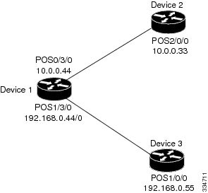
Figure 1. Sample network topology for directly connected LDP sessions
In this example, we configure:
MPLS hop-by-hop forwarding for the POS links between Device 1 and Device 2 and between Device 1 and Device 3
LDP for label distribution between Device 1 and Device 2
LDP for label distribution between Device 1 and Device 3
A loopback interface and IP address for each LSR that can be used as the LDP router ID
Configuring the mpls ip command on an interface triggers the transmission of discovery Hello messages for the interface.
The LDP configuration for the devices uses the mpls label protocol ldp command in interface configuration mode. To specify LDP for all interfaces, use the mpls label protocol ldp command in global configuration mode without any mpls label protocol commands for the interface.
Configuration example: Device 1
ip cef distributed                                !Assumes R1 supports distributed CEF
interface Loopback0                               !Loopback interface for LDP ID
 ip address 172.16.0.11 255.255.255.255
!
interface HundredGigE0/3/0
 ip address 10.0.0.44 255.0.0.0
 mpls ip                                            !Enable hop-by-hop MPLS forwarding
 mpls label protocol ldp
!
interface HundredGigE1/3/0
 ip address 192.168.0.44 255.0.0.0
 mpls ip                                            !Enable hop-by-hop MPLS forwarding
 mpls label protocol ldp
Configuration example: Device 2
ip cef distributed                                 !Assumes R2 supports distributed CEF
!
interface Loopback0                                !Loopback interface for LDP ID.
 ip address 172.16.0.22 255.255.255.255
 !
interface HundredGigE2/0/0
 ip address 10.0.0.33 255.0.0.0
 mpls ip                                            !Enable hop-by-hop MPLS forwarding
 mpls label protocol ldp
Configuration example: Device 3
ip cef                                              !Assumes R3 does not support dCEF
!
interface Loopback0                                 !Loopback interface for LDP ID.
 ip address 172.16.0.33 255.255.255.255
 !
interface HundredGigE1/0/0
 ip address 192.168.0.55 255.0.0.0
 mpls ip                                             !Enable hop-by-hop MPLS forwarding
 mpls label protocol ldp
Configuration example for indirectly connected LDP sessions
This section provides a sample network and configurations for establishing indirectly connected Label Distribution Protocol
(LDP) sessions.
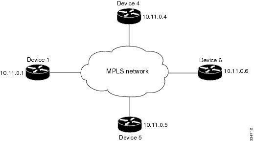
Figure 2. Sample network topology for indirectly connected LDP sessions
In this example:
Targeted sessions between Devices 1 and 4 use LDP. Devices 1 and 4 are both active.
Targeted sessions between Devices 1 and 6 use LDP. Device 1 is active and Device 6 is passive.
Targeted sessions between Devices 1 and 5 use LDP. Device 5 is active.
These examples assume that the active ends of the indirectly connected sessions are associated with tunnel interfaces, such
as MPLS traffic engineering tunnels. They show only the commands related to configuring LDP targeted sessions. The examples
do not show configuration of the applications that initiate the targeted sessions.
Configuration example: Device 1
Tunnel interfaces Tunnel14 and Tunnel16 specify LDP for targeted sessions associated with these interfaces. The targeted session
for Device 5 requires LDP. The mpls label protocol ldp command in global configuration mode makes it unnecessary to explicitly specify LDP as part of the configuration from the
Tunnel14 and Tunnel16.
ip cef distributed             !Device1 supports distributed CEF
mpls label protocol ldp        !Use LDP for all interfaces

interface Loopback0            !Loopback interface for LDP ID.
 ip address 10.25.0.11 255.255.255.255

interface Tunnel14             !Tunnel to Device 4 requiring label distribution
 tunnel destination 10.11.0.4  !Tunnel endpoint is Device 4
 mpls ip                       !Enable hop-by-hop forwarding on the interface

interface Tunnel15             !Tunnel to Device 5 requiring label distribution
 tunnel destination 10.11.0.5  !Tunnel endpoint is Device 5
 mpls label protocol ldp       !Use LDP for session with Device 5
 mpls ip                       !Enable hop-by-hop forwarding on the interface

interface Tunnel16             !Tunnel to Device 6 requiring label distribution
 tunnel destination 10.11.0.6  !Tunnel endpoint is Device 6
 mpls ip                       !Enable hop-by-hop forwarding on the interface
Configuration example: Device 4
The mpls label protocol ldp command in global configuration mode makes it unnecessary to explicitly specify LDP as part of the configuration for the
Tunnel41 targeted session with Device 1.
ip cef distributed               !Device 4 supports distributed CEF
mpls label protocol ldp          !Use LDP for all interfaces

interface Loopback0              !Loopback interface for LDP ID.
 ip address 10.25.0.44 255.255.255.255

interface Tunnel41               !Tunnel to Device 1 requiring label distribution
 tunnel destination 10.11.0.1    !Tunnel endpoint is Device 1
 mpls ip                         !Enable hop-by-hop forwarding on the interface
Configuration example: Device 5
Device 5 uses LDP for all targeted sessions. Therefore, its configuration includes the mpls label protocol ldp command.
ip cef                        !Device 5 supports CEF
mpls label protocol ldp       !Use LDP for all interfaces

interface Loopback0           !Loopback interface for LDP ID.
 ip address 10.25.0.55 255.255.255.255

interface Tunnel51            !Tunnel to Device 1 requiring label distribution
 tunnel destination 10.11.0.1 !Tunnel endpoint is Device 1
 mpls ip                      !Enable hop-by-hop forwarding on the interface
Configuration example: Device 6
By default, a device cannot be a passive neighbor in targeted sessions. Therefore, Device 1, Device 4, and Device 5 are active
neighbors in any targeted sessions. The mpls ldp discovery targeted-hello accept command permits Device 6 to be a passive target in targeted sessions with Device 1. Device 6 can also be an active neighbor
in targeted sessions, although the example does not include such a configuration.
ip cef distributed                       !Device 6 supports distributed CEF

interface Loopback0                      !Loopback interface for LDP ID
 ip address 10.25.0.66 255.255.255.255

mpls ldp discovery targeted-hellos accept from LDP_SOURCES
                                         !Respond to requests for targeted hellos
                                         !from sources permitted by acl LDP_SOURCES
ip access-list standard LDP_SOURCES      !Define acl for targeted hello sources
 permit 10.11.0.1                        !Accept targeted hello request from Device 1
 deny any                                !Deny requests from other sources

 Feedback