Configure Layer 3 virtualization

Layer 3 virtualization is a configuration process on the Cisco NX-OS device.

Layer 3 virtualization

Layer 3 virtualization is a technology that enables multiple virtual routing and forwarding instances (VRFs) on a single device, each with its own address space and routing tables.

  • Each VRF contains separate unicast and multicast route tables for IPv4 and IPv6.

  • Routing decisions are made independently for each VRF.

  • Each router has a default VRF and a management VRF.

VRF Types and Characteristics

The following sections describe the management VRF, default VRF, and the egress loadbalance resolution VRF.

  • Management VRF : Used exclusively for management purposes. Only the mgmt 0 interface can be in the management VRF, and it cannot be assigned to another VRF. No routing protocols can run in the management VRF (static only).

  • Default VRF : All Layer 3 interfaces exist in the default VRF until assigned to another VRF. Routing protocols run in the default VRF context unless another VRF context is specified. The default VRF uses the default routing context for all show commands and is similar to the global routing table concept in Cisco IOS.

  • Egress Loadbalance Resolution VRF : An internal VRF created automatically to assist in additional computation and resolution of routes for the VXLAN EVPN feature. This VRF is not configurable by the user and cannot be deleted. The VRF limit is increased from 4096 to 4097 to accommodate this new implicit VRF.


Note


  • The Egress Loadbalance Resolution VRF is not configurable by the user and cannot be deleted, as this is a benign empty VRF.

  • The VRF limit is increased from 4096 to 4097 to accommodate this new implicit VRF.

    For example:

    • Existing default configuration
       vdc switch id 1
      									limit-resource vrf minimum 2 maximum 4096 
    • New default configuration
       vdc switch id 1
      									limit-resource vrf minimum 2 maximum 4097 

VRF and routing

  • All unicast and multicast routing protocols support VRFs.

  • Routing parameters configured in a VRF are independent from those in another VRF for the same routing protocol instance.

  • Interfaces and route protocols can be assigned to a VRF to create virtual Layer 3 networks.

VRF and Routing Reference Information

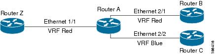
Each interface exists in only one VRF. A physical network can be split into multiple virtual networks using VRFs. Routers within the same VRF share route updates, while routers in different VRFs do not share route updates by default.

  • Routers Z, A, and B exist in VRF Red and form one address domain.

  • Router C is configured in a different VRF and does not share route updates with routers in VRF Red.

By default, Cisco NX-OS uses the VRF of the incoming interface to select which routing table to use for a route lookup. You can configure a route policy to modify this behavior and set the VRF that Cisco NX-OS uses for incoming packets.

  • Cisco NX-OS supports route leaking (import or export) between VRFs.

Figure 1. VRFs in a Network


Route leaking and importing routes from the default VRF

Route leaking and importing routes from the default VRF is a process that allows the transfer of IP prefixes between VRFs in Cisco NX-OS using import policies and route maps.

  • Import policies use route maps to specify which prefixes are imported into a VRF.

  • Both IPv4 and IPv6 unicast prefixes can be imported.

  • Imported prefixes cannot be reimported into another VRF through this policy.

Importing routes from the default VRF: details and considerations

To import IP prefixes from the default VRF, define match criteria in the import route map using standard route policy filtering mechanisms such as prefix lists or as-path filters.

  • You can create an IP prefix list or an as-path filter to define an IP prefix or range, and use that in a match clause for the route map.

  • Prefixes that pass through the route map are imported into the specified VRF using the import policy.


Note


Routes in the BGP default VRF can be imported directly. Any other routes in the default VRF should be redistributed into BGP first.


For more information, see the Guidelines and Limitations for VRF Route Leaking section.

VRF-Aware services

A fundamental feature of the Cisco NX-OS architecture is that every IP-based feature is VRF aware.

The following VRF-aware services can select a particular VRF to reach a remote server or to filter information based on the selected VRF:

See the appropriate configuration guide for each service for more information on configuring VRF support in that service.

Reachability

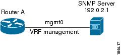
Reachability indicates which VRF contains the routing information necessary to get to the server providing the service. For example, you can configure an SNMP server that is reachable on the management VRF. When you configure that server address on the router, you also configure which VRF Cisco NX-OS must use to reach the server.

The following figure shows an SNMP server that is reachable over the management VRF. You configure Router A to use the management VRF for SNMP server host 192.0.2.1.
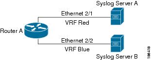
Figure 2. Service VRF Reachability


Filtering

Filtering allows you to limit the type of information that goes to a VRF-aware service based on the VRF. For example, you can configure a syslog server to support a particular VRF. The following figure shows two syslog servers with each server supporting one VRF. Syslog server A is configured in VRF Red, so Cisco NX-OS sends only system messages generated in VRF Red to syslog server A.

Figure 3. Service VRF Filtering


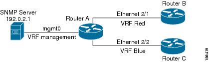
Combine reachability and filtering

You can combine reachability and filtering for VRF-aware services. You can configure the VRF that Cisco NX-OS uses to connect to that service as well as the VRF that the service supports. If you configure a service in the default VRF, you can optionally configure the service to support all VRFs.

The following figure shows an SNMP server that is reachable on the management VRF. You can configure the SNMP server to support only the SNMP notifications from VRF Red, for example.

Figure 4. Service VRF Reachability Filtering


Prerequisites for VRF

You must install the Advanced Services license to use virtual device contexts (VDCs) besides the default VDC. The license requirement for VRF is same as VDC.

Guidelines and limitations for VRFs

VRFs have the following configuration guidelines and limitations:

  • When you make an interface a member of an existing VRF, Cisco NX-OS removes all Layer 3 configurations. You should configure all Layer 3 parameters after adding an interface to a VRF.

  • You should add the mgmt0 interface to the management VRF and configure the mgmt0 IP address and other parameters after you add it to the management VRF.

  • If you configure an interface for a VRF before the VRF exists, the interface is operationally down until you create the VRF.

  • Cisco NX-OS creates the default and management VRFs by default. You should make the mgmt0 interface a member of the management VRF.

  • The write erase boot command does not remove the management VRF configurations. You must use the write erase command and then the write erase boot command.

Guidelines and limitations for VRF route leaking

VRF route leaking has the following configuration guidelines and limitations:

  • Route leaking is supported between any two non-default VRFs and from the default VRF to a non-default VRF.


    Note


    Route leaking between VRFs is not supported for MPLS Segment Routing (SR-MPLS).

    Route leaking between VRFs is not supported for BGP. A BGP speaker cannot connect to a peer IP that is routed through a different VRF.


  • Route leaking to the default VRF is not allowed because it is the global VRF.

  • You can restrict route leaking to specific routes using route map filters to match designated IP addresses.

  • Route synchronization between NX-OS and Guestshell container does not happen when the route points towards another VRF.

  • By default, the maximum number of IP prefixes that can be imported from the default VRF into a non-default VRF and vice versa is 1000 routes.

  • There is no limit on the number of routes that can be leaked between two non-default VRFs.

Default settings

The table lists the default settings for VRF parameters.

Table 1. Default VRF Parameters

Parameters

Default

Configured VRFs

Default, management

Routing context

Default VRF

Configure VRFs

If you are familiar with the Cisco IOS CLI, be aware that the Cisco NX-OS commands for this feature might differ from the Cisco IOS commands that you would use.

Create VRF

You can create a VRF.


Note


Any commands available in global configuration mode are also available in VRF configuration mode.


Procedure


Step 1

Use the configure terminal command to enter global configuration mode.

Example:

switch# configure terminal
switch(config)#

Step 2

[no] vrf context name

Example:

switch(config)# vrf context Enterprise
						switch(config-vrf)#

Creates a new VRF and enters VRF configuration mode. The name can be any case-sensitive, alphanumeric string up to 32 characters.

Using the no option with this command deletes the VRF and all associated configurations.

Step 3

(Optional) ip route {ip-prefix | ip-addr ip-mask} {[next-hop | nh-prefix] | [interface next-hop | nh-prefix]} [tag tag-value [preference]

Example:

switch(config-vrf)# ip route 192.0.2.0/8
						ethernet 1/2 192.0.2.4

Configures a static route and the interface for this static route. You can optionally configure the next-hop address. The preference value sets the administrative distance. The range is from 1 to 255. The default is 1.

Step 4

(Optional) show vrf [vrf-name]

Example:

switch(config-vrf)# show vrf Enterprise

Displays VRF information.

Step 5

(Optional) copy running-config startup-config

Example:

switch(config-vrf)# copy running-config
						startup-config
					

Saves this configuration change.


This example show how to create a VRF and add a static route to the VRF:

switch# configure terminal
				switch(config)# vrf context Enterprise
				switch(config-vrf)# ip route 192.0.2.0/8 ethernet 1/2
				switch(config-vrf)# exit
				switch(config)# copy running-config startup-config

Assign VRF membership to an interface

Procedure


Step 1

Use the configure terminal command to enter global configuration mode.

Example:

switch# configure terminal
switch(config)#

Step 2

interfaceinterface-typeslot/port

Example:

switch(config)# interface ethernet 1/2
						switch(config-if)#

Enters interface configuration mode.

Step 3

vrf membervrf-name

Example:

switch(config-if)# vrf member
						RemoteOfficeVRF

Adds this interface to a VRF.

Step 4

ip addressip-prefix/length

Example:

switch(config-if)# ip address
						192.0.2.1/16

Configures an IP address for this interface. You must do this step after you assign this interface to a VRF.

Step 5

(Optional) show vrfvrf-nameinterfaceinterface-typenumber

Example:

switch(config-vrf)# show vrf Enterprise
						interface ethernet 1/2

Displays VRF information.

Step 6

(Optional) copy running-config startup-config

Example:

switch(config-vrf)# copy running-config
						startup-config
					

Saves this configuration change.


This example shows how to add an interface to the VRF:


				switch# 
				configure terminal
				switch(config)# 
				interface ethernet 1/2
				switch(config-if)# 
				vrf member RemoteOfficeVRF
				switch(config-if)# 
				ip address 192.0.2.1/16
				switch(config-if)# 
				copy running-config startup-config
			

Configure VRF parameters for a routing protocol

You can associate a routing protocol with one or more VRFs. See the appropriate chapter for information on how to configure VRFs for the routing protocol. This section uses OSPFv2 as an example protocol for the detailed configuration steps.

Procedure


Step 1

Use the configure terminal command to enter global configuration mode.

Example:

switch# configure terminal
switch(config)#

Step 2

router ospf instance-tag

Example:

switch (config-vrf)# router ospf 201
						switch(config-router)#

Creates a new OSFPv2 instance with the configured instance tag.

Step 3

vrf vrf-name

Example:

switch(config-router)# vrf
						RemoteOfficeVRF
						switch(config-router-vrf)#

Enters VRF configuration mode.

Step 4

(Optional) maximum-paths paths

Example:

switch(config-router-vrf)# maximum-paths
						4

Configures the maximum number of equal OSPFv2 paths to a destination in the route table for this VRF. This command is used for load balancing.

Step 5

exit

Example:

switch(config-router-vrf)# exit
						switch(config-router)#

Exits VRF configuration mode.

Step 6

exit

Example:

switch(config-router)# exit
						switch(config)#

Exits router configuration mode.

Step 7

interface interface-type slot/port

Example:

switch(config)# interface ethernet 1/2
						switch(config-if)#

Enters interface configuration mode.

Step 8

vrf member vrf-name

Example:

switch(config-if)# vrf member
						RemoteOfficeVRF

Adds this interface to a VRF.

Step 9

ip address ip-prefix/length

Example:

switch(config-if)# ip address
						192.0.2.1/16

Configures an IP address for this interface. You must do this step after you assign this interface to a VRF.

Step 10

ip router ospf instance-tag area area-id

Example:

switch(config-if)# ip router ospf 201
						area 0

Assigns this interface to the OSPFv2 instance and area configured.

Step 11

(Optional) copy running-config startup-config

Example:

switch(config-if)# copy running-config
						startup-config
					

Copies the running configuration to the startup configuration.


This example shows how to create a VRF and add an interface to the VRF:

switch# configure terminal
				switch(config)# vrf context RemoteOfficeVRF
				switch(config-vrf)# exit
				switch(config)# router ospf 201
				switch(config-router)# vrf RemoteOfficeVRF
				switch(config-router-vrf)# maximum-paths 4
				switch(config-router-vrf)# interface ethernet 1/2
				switch(config-if)# vrf member RemoteOfficeVRF
				switch(config-if)# ip address 192.0.2.1/16
				switch(config-if)# ip router ospf 201 area 0
				switch(config-if)# exit
				switch(config)# copy running-config startup-config

Configure a VRF-Aware service

You can configure a VRF-aware service for reachability and filtering.

This section uses SNMP and IP domain lists as example services for the detailed configuration steps.

Procedure


Step 1

Use the configure terminal command to enter global configuration mode.

Example:

switch# configure terminal
switch(config)#

Step 2

snmp-server host ip-address [filter-vrf vrf-name] [use-vrf vrf-name]

Example:

switch(config)# snmp-server host
						192.0.2.1 use-vrf Red
					

Configures a global SNMP server and configures the VRF that Cisco NX-OS uses to reach the service. Use the filter-vrf keyword to filter information from the selected VRF to this server.

Step 3

vrf context vrf-name

Example:

switch(config)# vrf context Blue
						switch(config-vrf)#

Creates a new VRF.

Step 4

ip domain-list domain-name [all-vrfs] [use-vrf vrf-name]

Example:

switch(config-vrf)# ip domain-list List
						all-vrfs use-vrf Blue

Configures the domain list in the VRF and optionally configures the VRF that Cisco NX-OS uses to reach the domain name listed.

Step 5

(Optional) copy running-config startup-config

Example:

switch(config-vrf)# copy running-config
						startup-config
					

Saves this configuration change.


This example shows how to send SNMP information for all VRFs to SNMP host 192.0.2.1, reachable on VRF Red:

switch# configure terminal
				switch(config)# snmp-server host 192.0.2.1 for-all-vrfs use-vrf Red
				switch(config)# copy running-config startup-config

This example shows how to filter SNMP information for VRF Blue to SNMP host 192.0.2.12, reachable on VRF Red:

switch# configure terminal
				switch(config)# vrf context Blue
				switch(config-vrf)# snmp-server host 192.0.2.12 use-vrf Red
				switch(config)# copy running-config startup-config

Set the VRF scope

You can set the VRF scope for all EXEC commands (for example, show commands). Doing so automatically restricts the scope of the output of EXEC commands to the configured VRF. You can override this scope by using the VRF keywords available for some EXEC commands.

Procedure


routing-context vrf vrf-name

Example:

switch# routing-context vrf red
						switch%red#

Sets the routing context for all EXEC commands. The default routing context is the default VRF.

Note

 
Use the routing-context vrf default command to return to the default VRF scope.

To return to the default VRF scope, use the following command in EXEC mode:

Command

Purpose

routing-context vrf default

Example:

switch%red# routing-context vrf default
									switch#

Sets the default routing context.

Verify the VRF configuration

To display VRF configuration information, perform one of the following tasks.

Command

Purpose

show bgp process vrf [ vrf-name ]

Displays the information for all or one VRF.

show vrf [vrf-name]

Displays the information for all or one VRF.

show vrf [vrf-name] detail

Displays detailed information for all or one VRF.

show vrf [vrf-name] [interface interface-type slot/port]

Displays the VRF status for an interface.

Configuration examples for VRFs

For more information on VRF configuration, see Configure VRFs.

Note


  • The snmp-server host command is available both globally and under the vrf-context command. The following example shows the configuration under vrf-context .

  • Ensure that the host is configured on the switch before attaching any attributes (such as use-vrf, source-interface, filter-vrf etc).


Configuration Example for VRF Red
!SNMP server configuration under VRF context Red:
vrf context Red
  snmp-server host 192.168.0.12 use-vrf Red

!OSPF instance configuration to VRF Red
router ospf 201
  vrf Red

!interface configuration for VRF Red
interface ethernet 1/2
  vrf member Red
  ip address 192.168.0.1/16
  ip router ospf 201 area 0
  no shutdown

Configuration Example for VRF Red and Blue

!VRFs (Red, and Blue) creation
vrf context Red
vrf context Blue

!Configures OSPF per VRF
feature ospf
router ospf Lab
  vrf Red

router ospf Production
  vrf Blue
      router-id 192.168.1.0
  
interface ethernet 1/2
  vrf member Red
  ip address 192.168.0.1/16
  ip router ospf Lab area 0
  no shutdown

interface ethernet 10/2
  vrf member Blue
  ip address 192.168.0.1/16
  ip router ospf Production area 0
  no shutdown

!SNMP server configuration under VRF
!Note: Use the SNMP context “lab” to access the OSPF-MIB values for the OSPF instance Lab in VRF “Red” in this example.
!Create SNMP entities (v2c and/or v3) with appropriate groups/roles as needed on the switch to access the MIBs on the switch
!Create SNMP v3 user that can be used for SNMP queries, for example:
snmp-server user admin network-admin auth md5 password1
!Create SNMP v2c community  that can be used for SNMP queries, for example:
snmp-server community public ro

!Create SNMP contexts that can be used along with the entities for SNMP queries, for example:
snmp-server context lab instance Lab vrf Red
snmp-server context production instance Production vrf Blue

VRFs Configuration Example for Route Leaking

!VRF configuration
feature bgp 
vrf context red 
  ip route 192.168.33.0/32 192.168.3.1
  address-family ipv4 unicast
    route-target import 3:3
    route-target export 2:2
    export map test
    import map test
    import vrf default map test

interface Ethernet1/7 
  vrf member red
  ip address 192.168.3.2/24
  no shutdown

vrf context blue 
  ip route 192.168.44.0/32 192.168.4.1
  address-family ipv4 unicast
    route-target import 1:1
    route-target import 2:2
    route-target export 3:3
    export map test
    import map test
    import vrf default map test

interface Ethernet1/11 
  vrf member blue
  ip address 192.168.4.2/24
  no shutdown
!IP prefix list configuration
ip prefix-list test seq 5 permit 0.0.0.0/0 le 32 
route-map test permit 10
  match ip address prefix-list test

ip route 192.168.101.101/32 192.168.55.1 
!BGP per VRF assignment
router bgp 100
  address-family ipv4 unicast
    redistribute static route-map test

  vrf red
    address-family ipv4 unicast
      redistribute static route-map test

 vrf blue
    address-family ipv4 unicast
      redistribute static route-map test

Verification Example for route leaking between global and non-default VRFs


switch# show ip route vrf all 
IP Route Table for VRF "default"
'*' denotes best ucast next-hop
'**' denotes best mcast next-hop
'[x/y]' denotes [preference/metric]
'%<string>' in via output denotes VRF <string>

192.168.55.0/24, ubest/mbest: 1/0, attached
    *via 192.168.55.5, Lo0, [0/0], 00:07:59, direct
192.168.55.5/32, ubest/mbest: 1/0, attached
    *via 192.168.55.5, Lo0, [0/0], 00:07:59, local
192.168.101.101/32, ubest/mbest: 1/0
    *via 192.168.55.1, [1/0], 00:07:42, static
! 
IP Route Table for VRF "management"
'*' denotes best ucast next-hop
'**' denotes best mcast next-hop
'[x/y]' denotes [preference/metric]
'%<string>' in via output denotes VRF <string>

0.0.0.0/0, ubest/mbest: 1/0
    *via 10.29.176.1, [1/0], 12:53:54, static
10.29.176.0/24, ubest/mbest: 1/0, attached
    *via 10.29.176.233, mgmt0, [0/0], 13:11:57, direct
10.29.176.233/32, ubest/mbest: 1/0, attached
    *via 10.29.176.233, mgmt0, [0/0], 13:11:57, local
! 
IP Route Table for VRF "red"
'*' denotes best ucast next-hop
'**' denotes best mcast next-hop
'[x/y]' denotes [preference/metric]
'%<string>' in via output denotes VRF <string>

192.168.33.0/32, ubest/mbest: 1/0
    *via 192.168.3.1, [1/0], 00:23:44, static
35.35.1.0/24, ubest/mbest: 1/0, attached
    *via 35.35.1.2, Eth1/7, [0/0], 00:26:46, direct
35.35.1.2/32, ubest/mbest: 1/0, attached
    *via 35.35.1.2, Eth1/7, [0/0], 00:26:46, local
192.168.44.0/32, ubest/mbest: 1/0
    *via 192.168.4.1%blue, [20/0], 00:12:08, bgp-100, external, tag 100
192.168.101.101/32, ubest/mbest: 1/0
    *via 192.168.55.1%default, [20/0], 00:07:41, bgp-100, external, tag 100
! 
IP Route Table for VRF "blue" 
'*' denotes best ucast next-hop
'**' denotes best mcast next-hop
'[x/y]' denotes [preference/metric]
'%<string>' in via output denotes VRF <string>
192.168.33.0/32, ubest/mbest: 1/0
    *via 192.168.3.1%red, [20/0], 00:12:34, bgp-100, external, tag 100
192.168.44.0/32, ubest/mbest: 1/0
    *via 192.168.4.1, [1/0], 00:23:16, static
45.45.1.0/24, ubest/mbest: 1/0, attached
    *via 192.168.4.2, Eth1/11, [0/0], 00:25:53, direct
192.168.4.2/32, ubest/mbest: 1/0, attached
    *via 192.168.4.2, Eth1/11, [0/0], 00:25:53, local
192.168.101.101/32, ubest/mbest: 1/0
    *via 192.168.55.1%default, [20/0], 00:07:41, bgp-100, external, tag 100
switch(config)#

Configuration Example of Export VRF Default

The following example shows how to allow re-importation of already imported routes that is introduced in the “export vrf default” command to allow VPN imported routes to be re-imported into the default-VRF.

vrf context vpn1
  address-family ipv4 unicast
    export vrf default [<prefix-limit>] map <route-map> [allow-vpn]
  address-family ipv6 unicast
    export vrf default [<prefix-limit>] map <route-map> [allow-vpn]

Configuration Example of Border-leaf Configuration

  • To configure IP prefix list, use the following commands:

    !IP prefix list configuration
    ip prefix-list DEFAULT_ROUTE seq 5 permit 0.0.0.0/0
    route-map NO_DEFAULT_ROUTE deny 5
      match ip address prefix-list DEFAULT_ROUTE
    route-map NO_DEFAULT_ROUTE permit 10
    route-map allow permit 10
    
    !Creation of VRFs, and importing the route maps
    vrf context vni100
      vni 100
      ip route 0.0.0.0/0 Null0
      rd auto
      address-family ipv4 unicast
        route-target import 100:200
        route-target import 100:200 evpn
        route-target both auto
        route-target both auto evpn
        import vrf default map allow
        export vrf default map NO_DEFAULT_ROUTE allow-vpn
     
    vrf context vni200
      vni 200
      ip route 0.0.0.0/0 Null0
      rd auto
      address-family ipv4 unicast
        route-target import 100:100
        route-target import 100:100 evpn
        route-target both auto
        route-target both auto evpn
        import vrf default map allow
        export vrf default map NO_DEFAULT_ROUTE
    
    !BGP configuration
    router bgp 100
      address-family ipv4 unicast
        redistribute direct route-map allow
      address-family ipv6 unicast          
        redistribute direct route-map allow
    
      neighbor 192.168.101.101
        remote-as 100
        update-source loopback0
        address-family l2vpn evpn
          send-community extended
    
      neighbor 192.168.30.2
        remote-as 300
        address-family ipv4 unicast
    
      vrf vni100
        address-family ipv4 unicast
          network 0.0.0.0/0
          advertise l2vpn evpn
          redistribute direct route-map allow
    
      vrf vni200
        address-family ipv4 unicast
          network 0.0.0.0/0
          advertise l2vpn evpn
          redistribute direct route-map allow

Verification Example of BGP IPv4 Unicast configuration

switch(config-vrf)# show bgp ipv4 unicast 192.168.11.11/32
BGP routing table information for VRF default, address family IPv4 Unicast
BGP routing table entry for 192.168.11.11/32, version 14             
Paths: (1 available, best #1)
Flags: (0x08041a) on xmit-list, is in urib, is best urib route, is in HW

  Advertised path-id 1
  Path type: internal, path is valid, is best path, in rib
             Imported from 192.168.3.3:3:192.168.11.11/32 (VRF vni100)
  AS-Path: 150 , path sourced external to AS
    192.168.1.0 (metric 81) from 192.168.101.101 (192.168.101.101)
      Origin incomplete, MED 0, localpref 100, weight 0
      Received label 100
      Extcommunity:
          RT:100:100
          ENCAP:8
          Router MAC:5254.004e.a437
      Originator: 192.168.1.0 Cluster list: 192.168.101.101

  Path-id 1 advertised to peers:
    192.168.30.2

Verification Example of BGP IPv4 Unicast configuration per VRF


switch(config-vrf)# show bgp vrf vni100 ipv4 unicast 192.168.11.11/32
BGP routing table information for VRF vni100, address family IPv4 Unicast
BGP routing table entry for 192.168.11.11/32, version 8                    
Paths: (1 available, best #1)                                            
Flags: (0x08041e) on xmit-list, is in urib, is best urib route, is in HW 
  vpn: version 19, (0x100002) on xmit-list                               

  Advertised path-id 1, VPN AF advertised path-id 1
  Path type: internal, path is valid, is best path, in rib
             Imported from 192.168.1.0:3:[5]:[0]:[0]:[32]:[192.168.11.11]:[0.0.0.0]/224
  AS-Path: 150 , path sourced external to AS
    192.168.1.0 (metric 81) from 192.168.101.101 (192.168.101.101)
      Origin incomplete, MED 0, localpref 100, weight 0
      Received label 100
      Extcommunity:
          RT:100:100
          ENCAP:8
          Router MAC:5254.004e.a437
      Originator: 192.168.1.0 Cluster list: 192.168.101.101

  VRF advertise information:
  Path-id 1 not advertised to any peer

  VPN AF advertise information:
  Path-id 1 not advertised to any peer

Verification Examples of BGP IPv6 Unicast configuration

switch(config-vrf)# show bgp ipv6 unicast 2001:DB8:1::1/64
BGP routing table information for VRF default, address family IPv6 Unicast
BGP routing table entry for 2001:DB8:1::1/64, version 13               
Paths: (1 available, best #1)
Flags: (0x08041a) on xmit-list, is in u6rib, is best u6rib route, is in HW

  Advertised path-id 1
  Path type: internal, path is valid, is best path
             Imported from 192.168.3.3:3:2001:DB8:1::1/64 (VRF vni100)
  AS-Path: 150 , path sourced external to AS
    ::ffff:192.168.1.0 (metric 81) from 192.168.101.101 (192.168.101.101)
      Origin incomplete, MED 0, localpref 100, weight 0
      Received label 100
      Extcommunity:
          RT:100:100
          ENCAP:8
          Router MAC:5254.004e.a437
      Originator: 192.168.1.0 Cluster list: 192.168.101.101

  Path-id 1 advertised to peers:
    30::2

Verification Example of BGP IPv6 Unicast configuration per VRF


switch(config-vrf)# show bgp vrf vni100 ipv6 unicast 2001:DB8:1::1/64
BGP routing table information for VRF vni100, address family IPv6 Unicast
BGP routing table entry for 2001:DB8::1/128, version 6                        
Paths: (1 available, best #1)                                            
Flags: (0x08041e) on xmit-list, is in u6rib, is best u6rib route, is in HW
  vpn: version 7, (0x100002) on xmit-list                                 

  Advertised path-id 1, VPN AF advertised path-id 1
  Path type: internal, path is valid, is best path
             Imported from 192.168.1.0:3:[5]:[0]:[0]:[128]:[2001:DB8:1::1]:[0::]/416
  AS-Path: 150 , path sourced external to AS
    ::ffff:192.168.1.0 (metric 81) from 192.168.101.101 (192.168.101.101)
      Origin incomplete, MED 0, localpref 100, weight 0
      Received label 100
      Extcommunity:
          RT:100:100
          ENCAP:8
          Router MAC:5254.004e.a437
      Originator: 192.168.1.0 Cluster list: 192.168.101.101

  VRF advertise information:
  Path-id 1 not advertised to any peer

  VPN AF advertise information:
  Path-id 1 not advertised to any peer

Verification Example of IPv4 Route configuration

switch(config-if)# show ip route
IP Route Table for VRF "default"
'*' denotes best ucast next-hop 
'**' denotes best mcast next-hop              
'[x/y]' denotes [preference/metric] 
'%<string>' in via output denotes VRF <string>                         
   
0.0.0.0/0, ubest/mbest: 1/0
    *via vrf vni100, Null0, [20/0], 1d04h, bgp-100, external, tag 100 
192.168.1.0/32, ubest/mbest: 1/0 
    *via 192.168.103.1, Eth1/1, [110/81], 1d04h, ospf-100, intra
192.168.2.2/32, ubest/mbest: 1/0
    *via 192.168.103.1, Eth1/1, [110/81], 1d04h, ospf-100, intra 
192.168.3.3/32, ubest/mbest: 2/0, attached
    *via 192.168.3.3, Lo0, [0/0], 1d04h, local
    *via 192.168.3.3, Lo0, [0/0], 1d04h, direct
192.168.9.9/32, ubest/mbest: 1/0, attached
    *via 192.168.9.9%vni100, Lo9, [20/0], 1d03h, bgp-100, external, tag 100 
192.168.10.0/24, ubest/mbest: 1/0 
    *via 192.168.1.0, [200/0], 1d04h, bgp-100, internal, tag 100 (evpn) segid: 100 tunnelid: 0x1010101 encap: VXLAN                    
192.168.11.11/32, ubest/mbest: 1/0  
    *via 192.168.1.0, [200/0], 1d04h, bgp-100, internal, tag 150 (evpn) segid: 100 tunnelid: 0x1010101 encap: VXLAN 
192.168.20.0/24, ubest/mbest: 1/0 
    *via 192.168.2.2, [200/0], 1d04h, bgp-100, internal, tag 100 (evpn) segid: 200 tunnelid: 0x2020202 encap: VXLAN 
192.168.22.22/32, ubest/mbest: 1/0 
    *via 192.168.2.2, [200/0], 1d04h, bgp-100, internal, tag 250 (evpn) segid: 200 tunnelid: 0x2020202 encap: VXLAN 
192.168.30.0/24, ubest/mbest: 1/0, attached
    *via 192.168.30.1, Eth1/2, [0/0], 1d04h, direct 
192.168.30.1/32, ubest/mbest: 1/0, attached 
    *via 192.168.30.1, Eth1/2, [0/0], 1d04h, local 
192.168.33.0/32, ubest/mbest: 1/0 
    *via 192.168.30.2, [20/0], 1d04h, bgp-100, external, tag 300 
192.168.100.0/24, ubest/mbest: 1/0, attached 
    *via 192.168.100.3%vni100, Vlan100, [20/0], 1d04h, bgp-100, external, tag 100 
192.168.101.0/24, ubest/mbest: 1/0 
    *via 192.168.103.1, Eth1/1, [110/80], 1d04h, ospf-100, intra 
192.168.101.101/32, ubest/mbest: 1/0  
    *via 192.168.103.1, Eth1/1, [110/41], 1d04h, ospf-100, intra
192.168.102.0/24, ubest/mbest: 1/0
    *via 192.168.103.1, Eth1/1, [110/80], 1d04h, ospf-100, intra
192.168.103.0/24, ubest/mbest: 1/0, attached 
    *via 192.168.103.2, Eth1/1, [0/0], 1d04h, direct 
192.168.103.2/32, ubest/mbest: 1/0, attached
Verification Example of IPv6 Route configuration
switch(config-if)# show ipv6 route
IPv6 Routing Table for VRF "default"
'*' denotes best ucast next-hop 
'**' denotes best mcast next-hop              
'[x/y]' denotes [preference/metric] 
'%<string>' in via output denotes VRF <string>

::/0, ubest/mbest: 1/0
    *via vrf vni100, Null0, [20/0], 1d04h, bgp-100, external, tag 100 
2001:DB8:1::/64, ubest/mbest: 1/0, attached
    *via 2001:DB8:1::1, Eth1/1, [0/0], 1d04h, direct
2001:DB8:2:2::/128, ubest/mbest: 1/0
    *via 2001:DB8:103:1::1, Eth1/1, [110/81], 1d04h, ospf-100, intra 
2001:DB8:3:3::/128, ubest/mbest: 2/0, attached
    *via 2001:DB8:3:3::3, Lo0, [0/0], 1d04h, local
    *via 2001:DB8:3:3::3, Lo0, [0/0], 1d04h, direct
2001:DB8:9:9::/128, ubest/mbest: 1/0, attached
    *via 2001:DB8:9:9::9%vni100, Lo9, [20/0], 1d03h, bgp-100, external, tag 100 
2001:DB8:10::/64, ubest/mbest: 1/0 
    *via 2001:DB8:1::, [200/0], 1d04h, bgp-100, internal, tag 100 (evpn) segid: 100 tunnelid: 0x1010101 encap: VXLAN                    
2001:DB8:11:11::/128, ubest/mbest: 1/0  
    *via 2001:DB8:1::, [200/0], 1d04h, bgp-100, internal, tag 150 (evpn) segid: 100 tunnelid: 0x1010101 encap: VXLAN 
2001:DB8:20::/64, ubest/mbest: 1/0 
    *via 2001:DB8:2:2::2, [200/0], 1d04h, bgp-100, internal, tag 100 (evpn) segid: 200 tunnelid: 0x2020202 encap: VXLAN 
2001:DB8:22:22::/128, ubest/mbest: 1/0 
    *via 2001:DB8:2:2::2, [200/0], 1d04h, bgp-100, internal, tag 250 (evpn) segid: 200 tunnelid: 0x2020202 encap: VXLAN 
2001:DB8:30::/64, ubest/mbest: 1/0, attached
    *via 2001:DB8:30::1, Eth1/2, [0/0], 1d04h, direct 
2001:DB8:30::1/128, ubest/mbest: 1/0

Additional references

Additional references are resources or sections that provide further information related to a specific topic, such as implementing virtualization.

Related documents for VRFs

This section provides related documents for VRFs.

Related Topic

Document Title

VRFs

Cisco Nexus 9000 Series NX-OS Fundamentals Configuration Guide

Cisco Nexus 9000 Series NX-OS System Management Configuration Guide

Standards

No new or modified standards are supported by this feature, and support for existing standards has not been modified by this feature.

Standards

Title

No new or modified standards are supported by this feature, and support for existing standards has not been modified by this feature.