Frequency synchronization in networks
Frequency synchronization is a timing method that
-
distributes precision frequency across a network to ensure devices maintain accurate and consistent timing,
-
uses Quality Level (QL) information and assigned priority values to select the best available synchronization source, and
-
provides precise frequency but does not carry time-of-day information; time-of-day synchronization is achieved separately using packet-based protocols such as Precision Time Protocol (PTP).
Next generation networks must provide the ability to distribute precision frequency around the network. This is known as frequency synchronization. Precision frequency is required for applications such as circuit emulation and cell tower frequency referencing. To comply with ITU specifications for time-division multiplexing (TDM), use differential method circuit emulation. This requires a known, common precision frequency reference at each end of the emulated circuit.
Precisely synchronizing the time-of-day between different network devices is often desirable. This synchronization allows accurate calculation of the packet delay between two nodes in the network.
As SDH and SONET equipment is increasingly replaced by Ethernet equipment, this frequency synchronization ability is required over Ethernet ports. Synchronous Ethernet (SyncE) provides PHY-level frequency distribution of known, common precision frequency references.
To maintain SyncE links, a set of operations messages are required. These messages ensure each node derives timing from the most reliable source, and transfer information about the quality of the timing source used to clock the SyncE link. The ITU Standard G.8264 and its related recommendations document a simple protocol that provides a transport channel for Synchronization Status Messages (SSMs) over Ethernet.
Each timing source has a QL associated that indicates the accuracy of the clock. This QL information is transmitted across the network through SSMs over the Ethernet Synchronization Messaging Channel (ESMC) enabling the devices to identify the best available source for synchronization. Priority values can be assigned to particular timing sources on each switch to define a preferred network synchronization flow and help prevent timing loops. The combination of QL information and user-assigned priority levels enables each switch to choose which timing source to use to clock its SyncE as described in the ITU Standard G.781.
SyncE does not carry time-of-day information. Time-of-day synchronization is achieved using packet-based technologies, such as PTP. Clock sources such as GNSS/GPS can be used to inject accurate time-of-day and frequency into the network. Each switch in the network can select a source for time-of-day as well as a source for frequency (or select the same source for both, if possible and desirable), and pass its time-of-day information to its peers using a packet-based protocol. There is no equivalent to QL for time-of-day information, so selection between different sources for time-of-day is achieved using configuration.
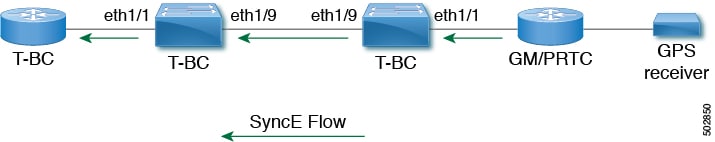
Hybrid SyncE-PTP with external PRC source
The hybrid SyncE-PTP topology helps achieve the end-to-end network precision frequency required for circuit emulation and cell tower frequency referencing.
The figure shows the external timing source as the Grandmaster/Primary Reference Time Clock (GM/PRTC) providing the timing source for the Telecom Boundary Clocks (T-BCs).
Timing sources
There are various timing sources that input timing clock signals into the system/network, and outputs of timing clock signals from the system as described below.
Timing inputs
Input clock signals can be received from the platform hardware either via inputs from timing sources like GPS/GNSS, from internal oscillators, recovered from the line of a SyncE enabled interface, or from timing over packet such as the Precision Time Protocol (PTP).
Platform independent (PI) software keeps a database of all these inputs, including a Quality Level (QL) and priority level associated with each. The priority level is configuration controlled, and the QL values can be obtained in a number of ways:
-
SyncE enabled interfaces receive SSMs via an Ethernet slow protocol (ESMC).
-
GPS and GNSS have fixed QL maintained by platform dependent (PD) software and notified to PI function.
-
PTP communicates its QL to the Frequency Synchronization PI software through the platform APIs.
-
A default QL value may be defined in the PD layer for the timing connectors, and internal oscillators.
-
Configuration may be set defining the QLs of timing sources.
Possible input sources include:
-
Internal Oscillator
-
Recovered SyncE Clock
-
External Clock 1588/PTP
-
External Clock (GPS)
-
Internal Clock (GNSS)
Timing outputs
The platform hardware can have a number of outputs for clock signals like timing clock outputs from SyncE and enabled interfaces for GPS (currently not supported).
The software keeps all these outputs in a database, including QL information associated with the clock signal being used to drive these outputs that may be explicitly configured. The QL information includes a QL value along with steps removed counters, the originator clock ID, and a series of flags containing information about the path from the originator clock to the current clock. The QL values are transmitted in the same manners as described for the inputs (that is, SyncE interfaces send ESMC SSMs).
Possible output sources:
-
SyncE
-
IEEE 1588/PTP: packet output is handled separately, in the PTP software.
Timing source selection points
At various stages in syncing timing clocks around the system, the platform has the potential to make a choice over which of the available timing clocks it is to use for further processing. These selection points define the flow of timing clock signals through the system, and eventually lead to the overall decision on which input timing source is to be used for timing outputs.
How these selection points are setup on each platform is hardware dependent, but the platform independent (PI) layer defines a generic selection point abstraction that can flexibly represent any platform selection point hardware, and allows each platform to define which selection points it has, and how they are wired together. The PI code can then control these selection points, tracking and distributing required information about the timing sources, and interacting with the platform dependent (PD) layer to discover what the result of the PD selection is at each stage.
PI timing source selection points include:
-
Available Timing Inputs – A number of timing clock inputs are available for the platform selection point hardware to choose between. The availability and associated QL information and priorities are tracked by PI software, which informs the PD layer which inputs are available, ranked in overall order along with their associated quality levels and priorities.
-
Platform Specific Selection – The platform layer makes a decision as to which of the inputs it is using based on the information obtained from PI, and other platform layer decisions (for example, hardware level qualification of the clock-signals). The actual decision may be made in PD software (and programmed into the hardware), or the decision may be made by the hardware itself and communicated back to the PD software.
-
Selected Timing Source Outputs – The platform passes the selected clock signal(s) through as output(s) from the selection point. The PD layer informs the PI software the status of the available inputs, and which input(s) have been selected.
The platform layer defines what the selection points are, and how they are connected to potential inputs, and to each other, and to potential outputs. At each of the PD defined selection points, the platform can choose how to interact with the PI software to represent its particular hardware to the PI software. The hardware doesn’t have to perform clocking qualification at each selection point. Each selection point simply represents any place where the hardware selects between multiple inputs, passing the clock from one or many inputs forward.
Only one selection point type for SyncE on the switch supervisor is supported. This is named T0 and 1588 selection points. The T0 selection point represents the sources and its selection for the SyncE DPLL. The 1588 selection point represents the sources and its selection for the Assist DPLL for 1588 PLL.

 Feedback