High-Performance Wireless for Above-Ground Mining
Available Languages
Bias-Free Language
The documentation set for this product strives to use bias-free language. For the purposes of this documentation set, bias-free is defined as language that does not imply discrimination based on age, disability, gender, racial identity, ethnic identity, sexual orientation, socioeconomic status, and intersectionality. Exceptions may be present in the documentation due to language that is hardcoded in the user interfaces of the product software, language used based on RFP documentation, or language that is used by a referenced third-party product. Learn more about how Cisco is using Inclusive Language.
- US/Canada 800-553-2447
- Worldwide Support Phone Numbers
- All Tools
 Feedback
 Feedback
Business Drivers for Digital Mining
Industrial Wireless Reference Architecture
Industrial Wireless Use Cases and Requirements
Autonomous Haulage Traffic Profiles and Technical Requirements
Tele-Remote Control Traffic Profiles and Technical Requirements
General Wireless Technology Recommendations
RF Planning Inputs and Site Assumptions
Antenna Selection, Placement, Installation, and Polarization
Antenna Selection and Placement
Environmental and Physical Design
End-to-End Service Prioritization
Industrial Wireless with Wi-Fi
Access, Trailer, and Vehicle Switching Role
Autonomous Haulage Wi-Fi Use-Case Architectures
Autonomous Haulage - Brownfield IRCM Upgrade Path
Autonomous Haulage Greenfield Target-State Architecture
Tele-Remote Control Wi-Fi Use-Case Architecture
Wi-Fi RF and Mobility Design Principles
Wi-Fi Frequency Design: 2.4 GHz and 5 GHz
Brownfield IRCM Mobility Caveat
Common Wi-Fi Configuration Guidance
Infrastructure AP Configuration Guidance
Vehicle WGB Configuration Guidance
Vehicle Switch Configuration Guidance
Infrastructure Switching Network Guidance
Monitoring and Configuration Guidance
Autonomous Haulage Wi-Fi Deployment Guidance
Autonomous Haulage WLC Guidance
Autonomous Haulage Infrastructure AP Guidance
Autonomous Haulage Vehicle WGB Guidance
Brownfield IRCM WLC and Mobility-Tunnel Guidance
Brownfield Non-IRCM Migration Guidance
AireOS 5520 Controller Considerations
IW3702 Workgroup Bridge Considerations
Autonomous Haulage Monitoring and Validation
Tele-Remote Control Wi-Fi Deployment Guidance
Tele-Remote Control WLC Guidance
Tele-Remote Control Infrastructure AP Guidance
Tele-Remote Control Vehicle WGB Guidance
Tele-Remote Control Vehicle Switch Guidance
Tele-Remote Control Infrastructure Switching Network Guidance
Tele-Remote Control Validation
Wi-Fi Operations, Monitoring, and Troubleshooting
Catalyst Center and Controller Visibility
Troubleshooting and Symptom Mapping
Commissioning and Change Control
Customer-Specific Values to Fill Before Production
Cisco Ultra Reliable Wireless Backhaul
URWB Infrastructure Components and Function
Access, Trailer, and Vehicle Switching Role
Device Management & Monitoring - IW-Service & IW-Monitor
URWB Operational Modes and Topology Roles
Fixed Point-to-Point Backhaul Connectivity
FluidMAX for Fixed Point-to-Multi-Point Topologies
Mobility (Fluidity) for Moving Mining Equipment
URWB Fluidity Handoff Decision
Fluidity Advanced Handoff Tuning for Vehicle Radio Units
Sector Antennas for Infrastructure Coverage
Directional Antennas for Fixed Backhaul and Point-to-Point Roles
Single-Frequency URWB Topology Example
Two-Frequency URWB Topology Example
Multi-Frequency Standalone URWB Topology Example
MPO Standalone URWB Topology Example
Tele-Remote Control Deployment Guidance
Single-Frequency URWB Topology Configuration
Two-Frequency URWB Topology Configuration
Multi-Frequency URWB Configuration
Regulatory Domain, Frequency Selection, and Output Power
Radio Slot Planning and Power Differences
Antenna Count and Maximum TX NSS
Polarization for Infrastructure and Vehicles
Ground Reflections, Delay Spread, and Mitigation
Path Validation for Moving Assets
QoS Marking, Remapping, and Queue-Based Features
QoS Priorities for Control and Video
RTS/CTS Threshold and Packet Size
A-MPDU, Queue Consistency, and Video Marking
Oversubscription and Headroom Control
AES Encryption and Radio Security Baseline
Segmentation and Management Access
Mesh-End Backhaul Check - Handoff Inhibition
Deployment Best Practices for Any Tele-Remote Control URWB Site
Link Backhaul Check - Handoff Inhibition
Commissioning and Acceptance Checklist
Troubleshooting and Symptom Mapping
KPI Framework and Evidence Model
Customer-Specific Appendix Content
Mining companies are seeking to drive operational and safety improvements into their production systems and assets through convergence and digitization. However, such initiatives require the secure connection of process environments via standard networking technologies to allow mining companies and their key partners access to a rich stream of new data, real-time visibility, optimized production systems and, when needed, secure remote access to the systems and assets in their operational environments.
The Cisco Industrial Automation (IA) Mining solution and relevant product technologies are an essential foundation to securely connect and digitize mining. The Cisco solution can help overcome customer barriers to digitization including security concerns, inflexible legacy networks, and complexity. The solution provides a proven and validated blueprint for connecting Industrial Automation and Control Systems (IACS) and production assets, improving industrial security, and improving plant data access and reliable operations. Following this best practice blueprint with Cisco market-leading technologies will help mining companies decrease deployment time, risk, complexity, and improve overall security and operating uptime.
This Cisco Validated Design focuses on the design, deployment, configuration and validation of a subset of the Cisco Industrial Automation Mining Reference Architectures. The key focus is providing wireless network connectivity for Autonomous Haulage operations and Tele-Remote Control operations, specifically tested with the Caterpillar suite of products.
Cisco Industrial Automation Mining Reference Architecture: https://www.cisco.com/c/en/us/td/docs/solutions/Verticals/Industrial_Automation/IA_Verticals/Mining/IA-Mining-DG/IA-Mining-DG.html
Business Drivers for Digital Mining
With growing pressures on the global mining industry, achieving breakthrough performance in all areas of the mining life cycle is fundamental to staying profitable. Mining companies will have to re-think how they have been operating in the past and adapt a digital future to improve productivity, safety, and efficiency.
Digital technologies have the potential to unlock new ways of managing variability and enhancing productivity. As the skilled labor pool shrinks, companies are seeking opportunities to better utilize their more experienced workers, and to gain new flexibility to meet future supply chain demands.
Connected devices and smart machines help capture real-time process information enabling better decision making. Gaining deeper insights into equipment health and operations can dramatically improve asset productivity. Remote operation centers are the evolution to the digitalization effort helping enable visibility, management, and remote command and control to allow for economies of scale.
The mine digitalization revolution and the development of technology has and will continue to enable huge improvements for mining operations. This requires a modern and standardized infrastructure that will support the digitalization process as well as openness and inter-operability between different systems.
Benefits of Digitalization in Mining:
● Improved mine safety
● Increased productivity
● Informed decision making
● Improved failure anticipation
● Reduced environmental impact
● Changing mine geometry:Roads move, benches advance, pits deepen, and ramp or dump locations shift, all of which can change RF coverage and signal paths.
● Obstructions and reflections:Parked equipment, moving machines, temporary structures, and highwalls can block or reflect wireless signals.
● Critical route locations:A route may appear clean in a prediction tool but still fail at turns, ramps, dump edges, loading approaches, or behind parked equipment.
● Use-case requirements:Coverage must be defined by the use case, such as reach, throughput, roam stability, packet loss, video usability, or recovery behavior.
● Workflow validation:Validation must prove the workflow on the actual route, at the expected speed, with the expected traffic load and machine posture.
● Operating windows:Shift changes, blasting windows, fueling, maintenance, and traffic peaks determine when network changes can be made safely.
● Revalidation triggers:Revalidate after meaningful changes to haul road or work-area layout, fleet behavior, application load, antenna placement, channel plan, or software.
Mining operations increasingly depend on connected machines, telemetry, video, remote operations, and automation to maintain production, quality, sustainability, and personnel safety. In open-pit environments, the wireless network must support those workflows across routes and work areas that change as roads move, benches advance, pits deepen, and equipment blocks or reflects RF energy.
This Cisco Validated Design (CVD) provides a repeatable architecture for deploying and operating high-performance wireless networks in above-ground mining environments. The design focuses on practical field deployment, predictable RF performance, centralized visibility, and operational processes.
The solution uses the mine operating model, traffic requirements, route layout, and infrastructure constraints to guide antenna selection, coverage planning, capacity planning, transport architecture, mobility validation, and ongoing revalidation. It is intended to support real mining workflows, including mobile equipment connectivity, control and telemetry traffic, operational video, maintenance access, and management visibility.
The result is an end-to-end architecture for above-ground mining wireless that connects operational requirements to RF design, physical installation, validation, and lifecycle management.
Industrial Wireless Reference Architecture
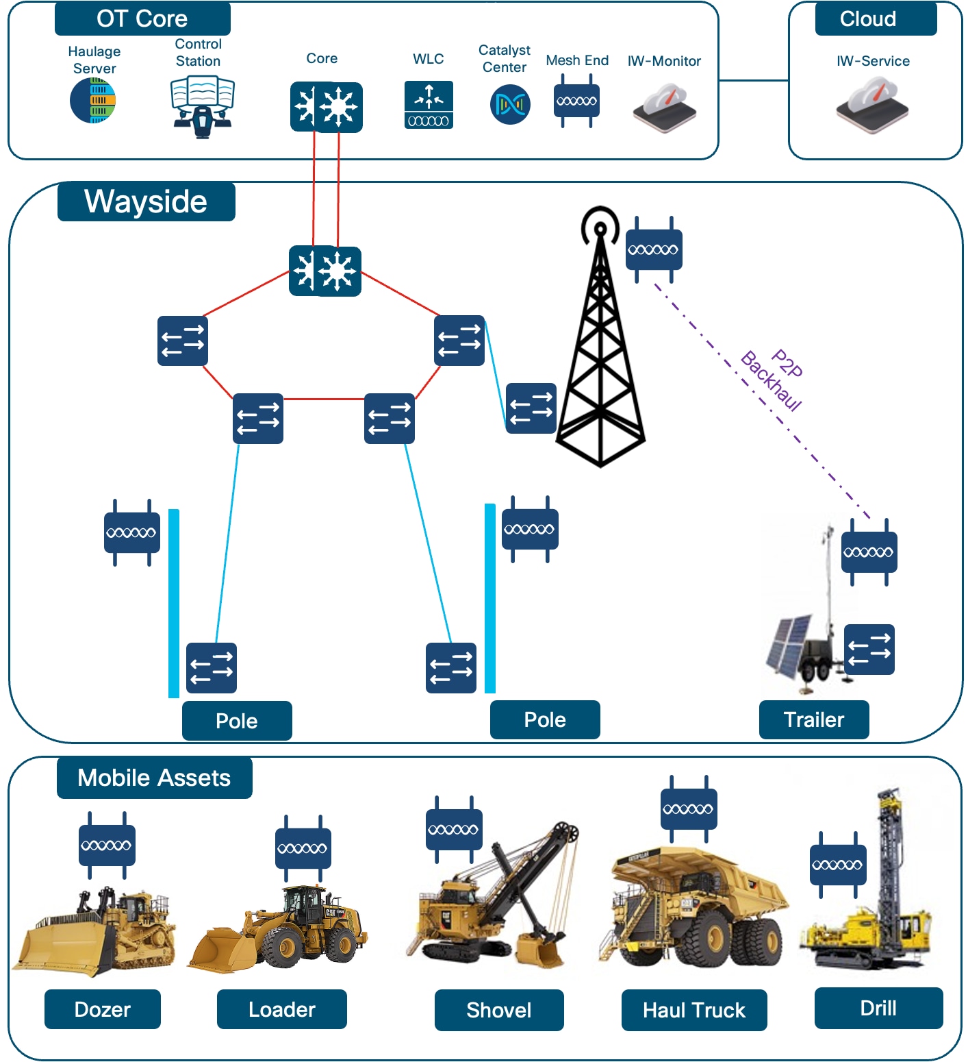
The reference architecture defines the end-to-end path for mining traffic from the application environment through the Operational Technology (OT) core or distribution layer, wireless infrastructure, vehicle-side radio, and machine LAN. It also identifies the management and monitoring points used to operate that path.
The architecture treats backhaul as part of the design. It shows where fiber, wireless point-to-point, and wireless point-to-multipoint links are used to reach active production zones. It also shows where traffic enters and leaves the wireless domain, and which controller or URWB domain owns the path.
Detailed RF, quality of service (QoS), multicast, and validation configuration is covered in the Wi-Fi, Ultra Reliable Wireless Backhaul (URWB), and validation sections. The result is a design record that shows the normal path, failure path, and validation boundary without requiring separate interpretation from drawings or configuration notes.
 |
This CVD is for wireless engineers, OT network engineers, automation teams, field installation teams, operations teams, and support engineers. It defines the various Cisco transport architectures. It does not define OEM autonomy logic, machine-safety application code, or third-party application internals.
It provides design guidance for RF, mobility, QoS, segmentation, security posture, platform roles, validation, and operations.
The validated scope includes Autonomous Haulage Wi-Fi, Tele-Remote Control Wi-Fi, and standalone URWB Tele-Remote Control designs. The table below lists the tested platform combinations. The architectures using legacy equipment should be seen as a temporary architecture while migrating to the permanent target architectures using modern equipment.
Target-state designs are the preferred architecture where the site can deploy them. Brownfield combinations are included to document controlled transition states and their limits.
The validated scenarios do not replace the site RF survey, route validation, final channel and power plan, packet captures, software matrix, Bill of Materials (BOM), as-built records, runbooks, or acceptance sign-off.
Table 1. Validated Scenarios in Scope
| Design Type |
Temporary/Target Architecture |
Controller |
Infrastructure AP |
Vehicle AP |
|
|
| Autonomous Haulage Wi-Fi IRCM |
Temporary |
AireOS WLC and Catalyst 9800 WLC |
1572, IW3702, and/or IW9167E |
IW3702 WGB and IW9167E WGB |
|
|
| Autonomous Haulage Wi-Fi |
Temporary |
Catalyst 9800 WLC |
IW9167E |
IW3702 WGB |
|
|
| Autonomous Haulage Wi-Fi |
Temporary |
AireOS WLC |
1572 and/or IW3702 |
IW9167E WGB |
||
| Autonomous Haulage Wi-Fi |
Target |
Catalyst 9800 WLC |
IW9167E |
IW9167E WGB |
||
| Tele-Remote Control Wi-Fi |
Target |
Catalyst 9800 |
IW9167E |
IW9167E WGB |
|
|
| Tele-Remote Control URWB Standalone |
Target |
IW9167E Mesh End |
IW9167E Mesh Points |
IW9167E mobility vehicle radio |
|
|
● Design for machine behavior first. Association state, RSSI, and a topology map do not matter if control, video, or telemetry is unstable on the route.
● Fix RF fundamentals and perform a site survey before tuning configuration settings: antenna placement, coverage overlap, line of sight, Fresnel zone clearance, interference, mounting height, and moving obstructions.
● Preserve headroom. The network must tolerate retries, bursts, additional vehicles, partial impairment, and mine changes.
● Separate validated behavior from assumptions. Keep evidence of a working route once tuned, configuration state, packet captures, and screenshots with the design record. These are crucial if troubleshooting is needed in the future.
Industrial Wireless Use Cases and Requirements
Autonomous Haulage uses self-driving mining trucks to execute planned haul cycles inside a controlled operating area. The truck receives assignments from the mine’s autonomy or fleet-management environment, travels to the loading tool, positions for loading, hauls material over the assigned route, dumps at the assigned location, and returns for the next cycle or maintenance activity. The onboard autonomy system manages truck movement, speed, following distance, obstacle response, positioning, and interaction with staffed equipment and light vehicles.
The value of Autonomous Haulage is consistency. Instead of each truck depending on an onboard operator, the mine runs haulage as a coordinated system with defined routes, operating rules, speed limits, interaction zones, and exception handling. The business drivers and operational benefits such as improved safety, more predictable haul cycles, reduced idle time, less bunching at loaders, better equipment utilization, and lower cost per ton are all realized through this approach.
The network supports the control and visibility path between the autonomous truck, field infrastructure, controllers, management systems, and operations teams. Typical traffic includes command and status messages, telemetry, health data, positioning-related data, alarms, map or mission updates, maintenance data, and sometimes video or diagnostic streams. The design must provide predictable mobility, bounded packet loss, usable latency, QoS treatment, segmentation, and enough operational visibility to prove the haul route works under real mining conditions.
The key design point is that the wireless network supports the Autonomous Haulage workflow, but the machine safety behavior must remain controlled by the autonomy system and its onboard safety logic.
Autonomous Haulage Traffic Profiles and Technical Requirements
Table 2. Autonomous Haulage Traffic Profiles
| Asset Type |
Onboard Devices |
Maximum Speed |
Traffic Characteristics |
| Haul Truck, Light Vehicle, Utility Vehicle |
1 to 2 wired devices |
60 km/h |
Baseline of approximately 500 kbit/s average, with periodic bursts of 1 to 2.5 Mbit/s every 30 minutes, but with strict expectations for continuity and interruption during roaming |
Treat these profiles as planning baselines only.
Final networking key performance indicator (KPI) scaling and network design must come from packet captures and application telemetry on representative assets and mission workflows. Average throughput is not enough; check burst size, packet distribution, multicast behavior, management chatter, retries, and application bursts during roaming.
Once you have the real-world requirements for your application measured you can generate the technical KPI requirements for your network These values should be treated as design targets for the Autonomous Haulage use and carried into RF design, roam-corridor engineering, multicast treatment, and QoS policy. Autonomous Haulage often has materially lower steady-state bandwidth demand, but the same discipline still applies: continuity, bounded interruption, and correct behavior at migration boundaries.
Tele-Remote Control allows an operator to control mining equipment from a remote operator station instead of from the machine cab. The machine remains under direct human control, but the operator uses video, machine telemetry, control interfaces, audio or alerts, and equipment feedback to perform the work from a safer and more comfortable location.
In open-pit mining, this use case is common for equipment that operates in higher-risk or uncomfortable areas, such as dozers working near stockpiles, dump edges, high walls, unstable ground, or high-vibration environments; drills operating on benches; and support equipment working in areas where operator exposure should be reduced.
The business value is operator safety and production continuity. Tele-Remote Control removes the operator from the machine while keeping the work active in areas where staffed operation may be unsafe, inefficient, or difficult to sustain. It can also reduce downtime during shift changes or restricted-access periods because the operator can continue working from a protected station.
For the wireless design, Tele-Remote Control is more latency-sensitive than many monitoring or dispatch applications because the operator is actively controlling the machine. The network must support reliable upstream video from the machine to the operator station, downstream control commands from the operator to the machine, machine telemetry, alarms, and management traffic. Packet loss, jitter, roaming delay, or poor video quality can directly affect operator confidence and productivity.
Tele-Remote Control Traffic Profiles and Technical Requirements
Table 3. Representative Vehicle and Traffic Profiles
| Asset Type |
Onboard Devices |
Maximum Speed |
Traffic Characteristics |
| Dozer, Loader, Excavator, Drill |
1 to 2 wired devices |
15 km/h |
Planning baseline around 6-8 Mbit/s average, < 1 % packet loss, < 100 ms of Max Latency |
Treat these profiles as planning baselines only.
Final networking KPI scaling and network design must come from packet captures and application telemetry on representative assets and mission workflows. Average throughput is not enough; check burst size, packet distribution, multicast behavior, management chatter, retries, and application bursts during roaming.
Tele-Remote Control requirements are driven first by control continuity, video continuity, roam stability, and loss tolerance.
Once you have the real-world requirements for your application measured you can generate the technical KPI requirements for your network These values should be treated as design targets for the Tele-Remote Control use and carried into RF design, roam-corridor engineering, multicast treatment, and QoS policy. Tele-Remote Control often has materially lower steady-state bandwidth demand, but the same discipline still applies: continuity, bounded interruption, and correct behavior at migration boundaries.
General Wireless Technology Recommendations
This section defines the RF planning inputs, antenna practices, coverage planning, capacity planning, and physical design considerations that apply across mining wireless deployments. It does not prove final performance by itself and does not replace a physical site survey. Final performance is validated after the selected architecture is tested on the actual operating routes with representative traffic and movement.
RF Planning Inputs and Site Assumptions
Open-pit wireless design should begin with the real operating conditions the network must support. Before selecting antenna locations, defining coverage boundaries, or setting capacity targets, gather the data that will materially affect RF performance.
At minimum, capture the following planning inputs:
Operating model:Machine types, active vehicles per zone, expected vehicle speed, stop time, queueing areas, and current or planned operating routes.
Critical locations:Turns, ramps, dump edges, loading approaches, maintenance areas, and other locations where coverage or roaming performance is most likely to be stressed.
Traffic model:Control, telemetry, video, management, diagnostics, maintenance, and software update traffic, including expected load, peak load, packet-size distribution, and simultaneous video streams.
Mine environment:Expected layout changes, including pit depth, bench movement, route changes, temporary obstructions, parked equipment, and other conditions that may block or reflect RF energy.
Infrastructure constraints:Candidate wireless locations, antenna placement options, power, backhaul, maintenance access, grounding, lightning protection, naming, addressing, and change-control requirements.
Use these inputs to plan RF coverage and capacity. Coverage planning should define the intended service area, expected cell edge, required overlap between coverage areas, and locations where performance may degrade because of movement, obstruction, reflection, weather, or cell-edge operation. Capacity planning should account for the number of active machines, expected and peak traffic load, retries, management overhead, and usable headroom during normal operation and temporary impairment.
Validate the proposed design in the field using the planned route, operating speed, traffic profile, and machine posture expected in production. Success criteria should reflect the use case, such as coverage reach, throughput, roam stability, packet loss, latency, video usability, and recovery behavior. Where results do not meet the design targets, the RF design should be refined and the validation repeated before production operations begin.
Recheck the RF design against a baseline when the mining environment, fleet behavior, application load, antenna placement, channel plan, infrastructure location, or software changes in a way that could affect wireless performance.
Antenna Selection, Placement, Installation, and Polarization
Antenna Selection and Placement
● Select antennas based on the operating area, route predictability, and movement pattern. Use directional or sector antennas where machines follow known routes, ramps, or work faces and RF energy needs to be focused. Use omnidirectional antennas in staging areas, workshops, parking zones, and broad work areas where movement is less predictable.
● For vehicle-mounted antennas, prioritize clear exposure toward the infrastructure, protection from physical damage, short and serviceable cable paths, and minimal blockage from the cab, dump body, attachments, handrails, or other metal structures like vehicle signage boards.
● For infrastructure antennas, prioritize line of sight, elevation, controlled overlap, maintainability, and separation from other antennas. Poor placement can create symptoms that look like platform or configuration problems, including weak cell edges, unstable transitions, retries, low data rates, and intermittent video.
Follow the hardware installation guide and antenna datasheet for mounting, sealing, torque, bend radius, grounding, and environmental requirements. At a design level, capture the installation items that affect RF reliability:
● Keep RF cable lengths as short as practical and the same length between ports.
● Avoid tight bends, kinks, crushed cables, and unnecessary service loops.
● Protect unused connectors with caps.
● Weather-seal exposed RF connectors.
● Route cables away from snagging, washdown, vibration, and pinch points.
● Inspect connector seals and cable condition during routine maintenance.
Polarization is part of the RF design, not just an antenna catalog choice. The infrastructure and vehicle antenna polarization should be planned together so the link preserves margin as machines move, turn, climb, dump, or operate near reflective surfaces.
Matched polarization helps maintain received signal strength, spatial-stream stability, and retry behavior. A mismatch can look like a power, MCS, or configuration problem when the real issue is poor coupling between the infrastructure and vehicle antennas.
Use dual-polarized antenna designs as the normal starting point for two-chain mining links unless the route, antenna system, or use case clearly justifies a different choice. An example of a deviation would be if the system uses two different singularly polarized antennas on the infrastructure and vehicle side. For example, using Port 1 V-polarized and Port 2 H-polarized antennas. The vehicle antenna system should match the infrastructure polarization plan and the vehicle mounting geometry. If one side is dual-polarized and the other side is effectively single-polarized or misaligned, one chain may underperform and reduce overall link stability.
At minimum:
● Match infrastructure and vehicle polarization plans deliberately.
● Do not assume different antenna kits will align correctly by default.
● Validate polarization on the real route with real machine posture, not only with static close-in testing.
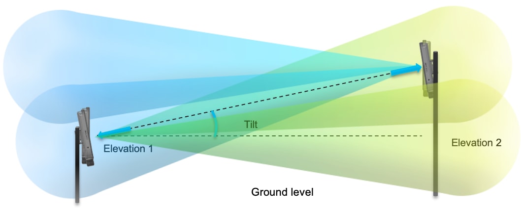
Antenna alignment must account for distance, elevation difference, mounting height, and the expected direction of movement. Visible line of sight is not enough. The design should target at least 60 percent clearance of the first Fresnel zone across the intended path.
Realign and revalidate the path after antenna height, bracket position, pole location, or vehicle mounting changes. Small mechanical changes can materially affect signal quality, overlap, and cell-edge behavior.
Environmental and Physical Design
All infrastructure must meet appropriate industrial standards for ingress protection, temperature tolerance, vibration resistance, corrosion mitigation, and weatherproof installation.
Maintainability is also a design variable. An access point (AP) or antenna position that is excellent on paper may be poor if the site cannot inspect it safely, if it is likely to be damaged by operating equipment, or if field replacement requires an impractical outage process. Production mining designs must remain maintainable by real site teams under real site constraints.
End-to-End Service Prioritization
Protect traffic in this order: machine control, safety-relevant telemetry, usable video, then management and background traffic.
Configure QoS correctly at every point in the path so the same service intent is preserved from source application to receiver.
The QoS path may include:
● Application marking
● Vehicle switch
● Vehicle radio
● Infrastructure radio
● Switching and routing infrastructure
● Wireless LAN Controller (WLC) policy or URWB Mesh End
Do not assume one correct DSCP or queue value at the source is enough. If the marking, queue, or trust state changes in the middle of the path, the design is incomplete.
Operate the environment with measurable KPIs and actionable alerting. Maintain a live operating view of infrastructure AP health, vehicle behavior, roaming outcomes, RF quality, authentication failures, controller events, backhaul path status, and traffic-policy health.
● Keep historical data long enough to compare current behavior to the validated baseline.
● Define alarm thresholds that trigger action before the operator reports loss of control or unusable video.
● Use dashboards and event timelines that OT and network teams can review together during an incident.
If changes in roaming, path quality, or application outcome cannot be investigated, the deployment is not operationally complete.
For operations, use Catalyst Center as the primary Wi-Fi operations platform, use IW-Service and IW-Monitor for URWB, use Cisco ISE logs and policy views where identity-driven access is part of the design, and use Cisco Cyber Vision for OT asset and industrial-protocol visibility. More detail on these products can be found later in the document.
Industrial Wireless with Wi-Fi
Table 4. Wi-Fi Infrastructure Roles
| Component Role |
Preferred Cisco Direction |
Primary Function |
| Core Switch |
Catalyst 9x00 |
Provides resilient OT core connectivity and deterministic transport for the core of the network |
| Distribution Switch |
Cisco IE9300 |
Provides ruggedized aggregation between wired and wireless segments of the OT network |
| Access, Trailer, and Vehicle Switching |
Cisco IE3x00 |
Provides ruggedized local wired attachment in trailers, field cabinets, and on vehicles |
| Wireless LAN Controller |
Catalyst 9800 WLC |
Provides centralized Wi-Fi controls |
| Infrastructure Access Points |
IW9167E |
Provides Wi-Fi backhaul and Wi-Fi mobility coverage |
| Workgroup Bridge (WGB) Clients |
IW9167E |
Provides the vehicle-side Wi-Fi transport edge for machine systems |
| Network Management |
Catalyst Center |
Provides network inventory, assurance, lifecycle management, and operational visibility for the Wi-Fi environment |
| Network Security |
Identity Services Engine (ISE) |
Provides centralized authentication, authorization, profiling, and policy enforcement for wireless, switching, and management access. |
| Network Visibility |
Cyber Vision |
Provides OT asset visibility, industrial protocol awareness, and communication-pattern monitoring for devices on the mining network. |
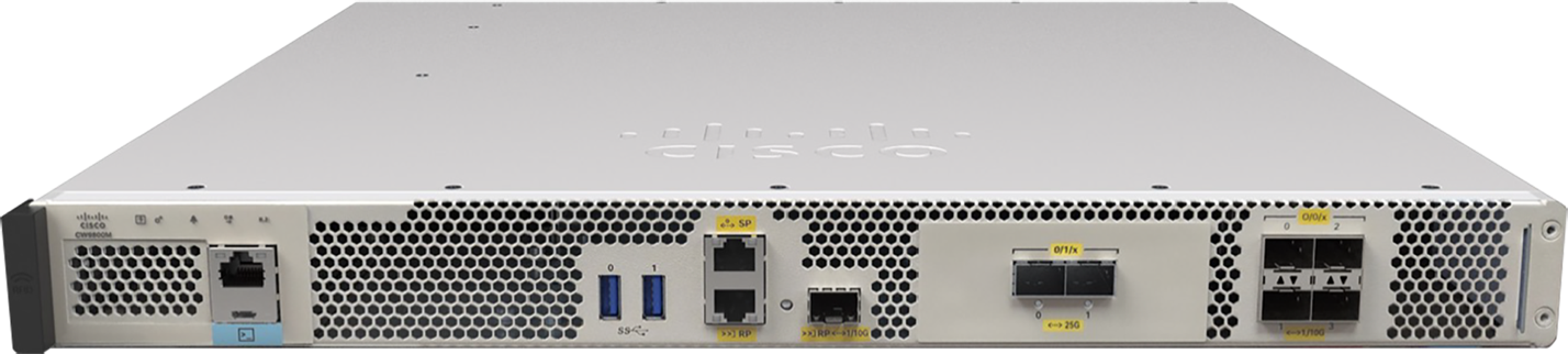
The core device should be the Cisco Catalyst 9x00.
What matters is resilient connectivity, sufficient throughput, deterministic queueing, and the operational behavior required by the site architecture.
Many customers already have OT core standards. The design avoids unnecessary friction when a core platform choice is not fundamental to the wireless architecture.
Core requirements are explicit: resilient uplinks from the wireless controllers and distribution layer, predictable treatment of priority traffic classes, sufficient buffering and capacity for aggregated wireless traffic, and clean integration with the rest of the OT environment. Where the site has separate IT and OT cores, document where the wireless control and machine traffic terminate and how policy boundaries are maintained between the environments.
The Cisco Catalyst IE9300 should be used as the distribution switch where ruggedized aggregation, uplink flexibility, environmental hardening, and resilient site backhaul are required. The distribution layer is where production wireless service is aggregated, protected, and extended into the field.
The IE9300 role in this design is to aggregate field-side AP and switching segments, provide robust uplink options toward the core, redundancy through stacking, preserve QoS treatment consistently, and survive the environmental and operational demands of mining sites. The distribution layer should be engineered so that a single field event or maintenance activity does not create disproportionate disruption across multiple mobility corridors. The operational goals of the mine should be able to survive in a temporarily degraded network state, which could occur when maintenance activities are planned, or unexpected single point failures occur.
Access, Trailer, and Vehicle Switching Role
Access, trailer, and vehicle switching should be selected from the Cisco Industrial Ethernet portfolio according to environmental rating, power model, port density, uplink needs, mounting method, serviceability, and local standards. Detailed switch selection for IE3100, IE3100H, IE3400, IE3400H, IE3500, or IE3500H should be guided by Cisco switch selection documentation in the references section.
The Catalyst 9800 WLC is the policy, mobility, and wireless control point for the Wi-Fi architecture.
Size it for AP count, client count, mobility scale, policy complexity, and growth.
When staged migration (brownfield) environments are required, document the legacy controller and the new controller behavior in operational terms.
The site team should be able to explain what happens to a vehicle session during a roam, which mobility-tunnel dependencies exist between controller domains, and how faults are isolated.
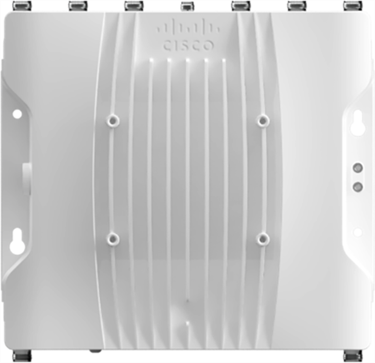
The Cisco Catalyst IW9167E is the industrial wireless infrastructure access point used for above-ground mining Wi-Fi coverage and wireless backhaul. In this design, infrastructure APs provide the fixed RF access layer for authorized mobile clients, vehicle radios, and fixed wireless links across haul roads, loading areas, dumps, stockpiles, workshops, and tele-remote operating zones.
The IW9167E combines a heavy-duty industrial form factor with flexible RF design options. The platform provides 4x4 radios for 2.4 GHz, 5 GHz, and 5/6 GHz operation, with eight external antenna ports across three radio interfaces. This allows antenna type, antenna orientation, mounting height, channel plan, transmit power, and coverage overlap to be engineered around the route layout and the mobility pattern being served.
Infrastructure AP placement should be driven by the intended service path rather than treated as generic wireless coverage. Each AP should have a documented role: the road segment or work area it serves, the client types it is expected to support, the antenna pattern required for that area, and the neighboring APs with which it must maintain usable overlap. The RF design should validate RSSI, SNR, supported data rates, channel reuse, and roaming behavior under representative vehicle movement and production traffic.
The IW9167E workgroup bridge (WGB) is the hardened vehicle-side AP. The WGB bridges the mobile machine's onboard Ethernet network to the WLAN, carrying traffic for control interfaces, video endpoints, telemetry, maintenance access, and other onboard systems.
The IW9167E is used for this role because it provides a hardened industrial platform with extended temperature support, external antenna flexibility, and alignment with the IW9167E infrastructure APs used elsewhere in the design. It can be powered from a vehicle DC source when 24 to 48 VDC is available.
Vehicle power should be checked during migration. Older IW3702 APs accepted DC input down to 12 VDC, so an existing vehicle power feed should not be assumed compatible with the IW9167E without verifying voltage range, power conditioning, wiring, and protection.
The recommended wireless controller platform is a Catalyst 9800 model sized for AP count, client count, policy scale, multicast requirements, and expected growth. High availability uses SSO where practical in a centralized design, or a clearly defined resilience model where site architecture requires a different operating approach. Controller placement, aggregation design, and critical uplinks must avoid single points of failure and must be documented in a way that site operations teams can actually support.
IW9167E infrastructure AP placement follows engineered RF intent. APs are positioned to create stable mobility corridors along haul roads and within operating areas, with mounting height, antenna type, and antenna gain selected for local terrain, road geometry, and line-of-sight behavior. Vehicle-mounted WGBs and their antennas must be treated as engineered components of the design, not afterthoughts, because poor vehicle placement can negate otherwise sound infrastructure design.
Logical segmentation separates machine control, video, telemetry, management, and administrative access using VLANs, VRFs, ACLs, or equivalent controls as required by the site architecture. Segmentation is a baseline requirement because it limits fault propagation, improves policy enforcement, and protects critical traffic paths. Logical data paths must be documented clearly enough that a reader can tell which traffic classes are permitted across each boundary and which traffic classes should never be mixed.
Physical design must include grounding, lightning protection, enclosure integrity, weatherproofing, cable protection, and maintainable installation practices. Physical reliability is treated as part of network reliability because failures in installation discipline create the same operational impact as failures in RF design. A technically correct wireless design can still fail operationally if antennas are mounted where they cannot be maintained safely, if cable routes are repeatedly damaged by vehicle wash or vibration, or if field cabinets are difficult to inspect and restore quickly.
Autonomous Haulage Wi-Fi Use-Case Architectures
Design rule: Treat brownfield states as controlled temporary migration architectures, not as the destination architecture. The target architecture is Catalyst 9800 WLCs, IW9167E infrastructure APs, and IW9167E WGBs.
This section covers two Autonomous Haulage wireless architecture states:
Table 5. Layers and Target Architecture States
| Layer |
Existing / Legacy |
Target State |
| WLCs |
AireOS 5520 |
Catalyst 9800 |
| Infrastructure radios |
1572 / IW3702 APs |
IW9167E APs |
| Vehicle radios |
IW3702 WGB |
IW9167E WGB |
Brownfield Migration Paths
Table 6. Brownfield Architecture Components Autonomous Haulage Migration and Target Architecture States
| Architecture State |
Purpose |
Resulting Architecture |
| Brownfield IRCM Migration |
Used when legacy and target wireless domains must coexist during a controlled migration |
AireOS 5520 and Catalyst 9800 coexist; 1572/IW3702 and IW9167E APs coexist; IW3702 and IW9167E WGB-equipped vehicles may coexist in the fleet |
| Greenfield Target State |
Used for new deployments or completed migrations |
Catalyst 9800 WLCs with IW9167E infrastructure APs and IW9167E WGBs |
Autonomous Haulage - Brownfield IRCM Upgrade Path
Scenario: This is the brownfield mixed-controller migration scenario. AireOS 5520 WLCs with 1572 or IW3702 infrastructure APs remain active while Catalyst 9800 WLCs with IW9167E infrastructure APs are introduced. The vehicle fleet may include IW3702 WGB-equipped vehicles, IW9167E WGB-equipped vehicles, or both during the migration period.
Use this when a production route must cross a deliberately engineered controller overlap before the site can complete the refresh. The IRCM transition area should be intentionally placed where vehicles can roam under controlled conditions and where the design minimizes the number of IRCM roam events required during normal production movement.
Design constraints:
● Choose the roads, intersections, loading approaches, or dump exits where an IRCM roam should occur because that location gives the best control over vehicle speed, line of sight, AP candidate quality, and operator risk.
● Limit the IRCM overlap to the planned transition area. Avoid broad uncontrolled overlap that creates unnecessary IRCM roam opportunities elsewhere in the mine.
● Align SSID intent, security posture, VLAN and policy attachment, QoS, multicast treatment, and mobility-tunnel configuration across the two controller domains.
● Do not use RAP-to-MAP mesh links between APs joined to different controller domains. Cross-controller RAP/MAP mesh is not supported; keep mesh relationships inside a single controller domain and use engineered RF overlap for vehicle roaming between domains.
● Do not configure a static foreign/anchor relationship on the WLAN. Allow the WLCs to perform auto-anchoring.
● Treat any partial refresh state as a temporary migration condition.
● If Catalyst 9800 WLCs and IW9167E APs are deployed before the vehicle refresh, legacy IW3702 WGB behavior remains the limiting factor. One key limitation is that IW3702 WGBs do not support 802.11r.
● If IW9167E WGBs are deployed before the infrastructure refresh, the legacy AireOS 5520 and 1572/IW3702 AP domain remains the limiting factor.
● Account for regulatory and platform changes that affect radio output power on newer devices compared to legacy devices. When replacing infrastructure APs, do not assume the new AP will provide the same cell size as the legacy AP.
● If the vehicle WGBs are upgraded first, validate both downstream and upstream RF. The IW9167E WGB may hear the legacy infrastructure radio better than the legacy infrastructure radio hears the IW9167E WGB. This can be missed unless received signal strength is reviewed from both radio perspectives.
● If an IW9167E WGB-equipped vehicle must cross the IRCM boundary into an area with legacy infrastructure, validate that the route has appropriate upstream signal from the vehicle to the infrastructure APs.
● Prefer migrating infrastructure APs and vehicle WGBs together within the same geographic operating area when practical, because it reduces asymmetric RF behavior and avoids mixing radio generations across the same production route.
● Do not assume target-state roaming, security, or performance behavior until the controller, infrastructure APs, and vehicle WGBs have all been migrated and validated together.
● Document the exit plan from the brownfield state to the greenfield target state.
Design risk is treating the boundary as generic coexistence instead of a controlled transition zone.
The vehicle needs enough usable signal from both sides of the overlap to complete the roam at the planned transition point, but not so much uncontrolled overlap that the mine creates extra IRCM roam opportunities in the wrong physical locations. Partial refresh conditions must also stay explicit: upgrading only the infrastructure side or only the vehicle side does not make the route behave like the target architecture.
Validation evidence:
● Controller mobility evidence, tunnel state, client event history, and route-based roam captures.
● Compatibility validation for the actual client and infrastructure combinations present during migration.
● Received signal strength reviewed from both infrastructure-to-vehicle and vehicle-to-infrastructure perspectives.
● Production-speed testing for the actual vehicle classes, traffic profiles, and route segments that will cross the boundary.
● Documentation of temporary concessions, such as narrower route scope, conservative speed, reduced video profile, or stricter operating boundary.
● A design record that separates platform interoperability from proven route outcome.
● A target-state exit plan showing how the site will complete migration to Catalyst 9800, IW9167E infrastructure APs, and IW9167E WGBs.
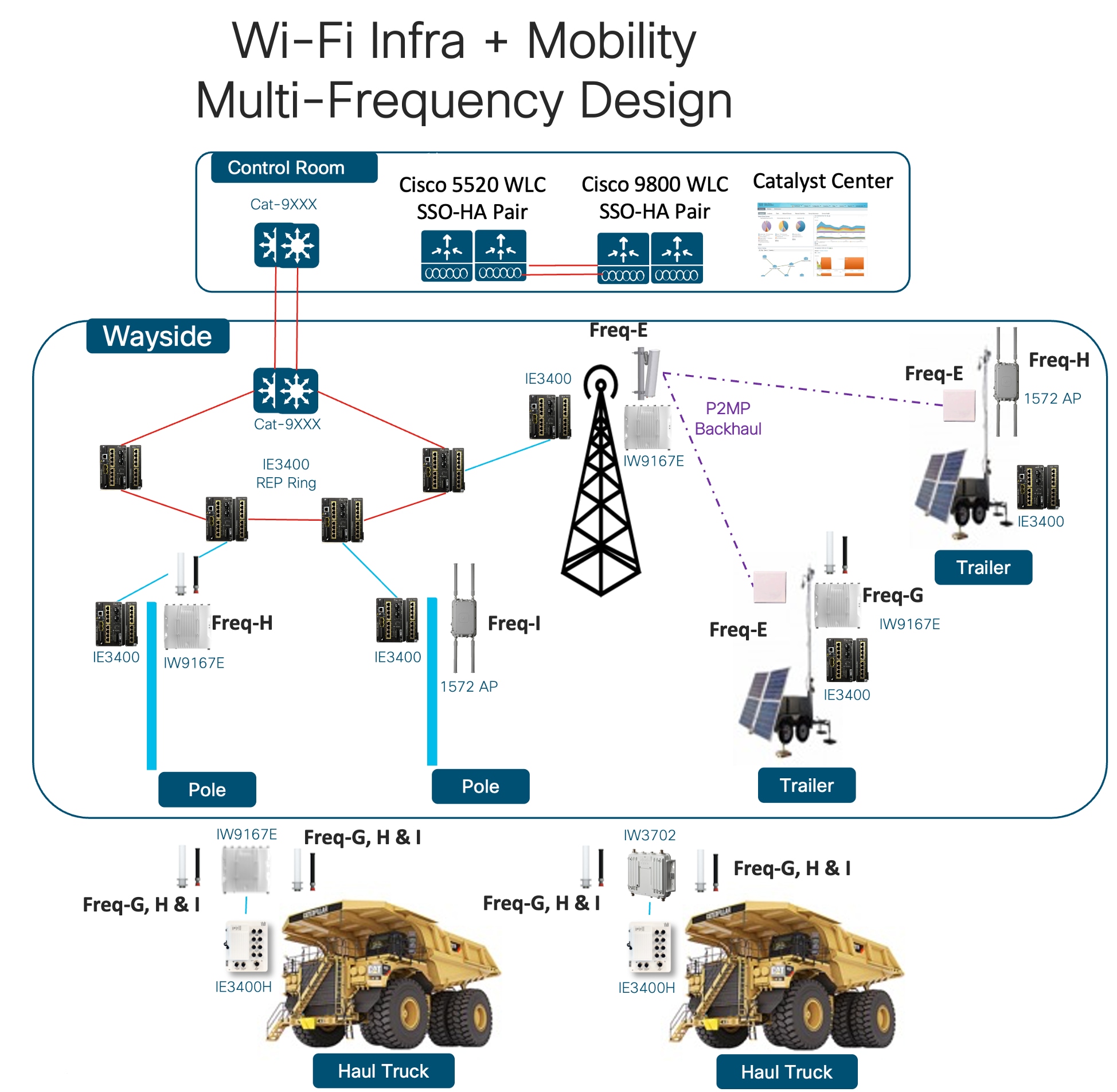
Table 7. Autonomous Haulage Brownfield IRCM Components
| Component Role |
Platform or Device |
Function in This Architecture |
Deployment Notes |
| Legacy Controller Domain |
AireOS 5520 WLC |
Provides the legacy brownfield wireless control domain during staged migration |
Retains legacy operational state while the new domain is introduced |
| Legacy Infrastructure AP |
1572 / IW3702 |
Delivers brownfield infrastructure coverage in the existing controller domain |
Maintain validated RF overlap into the engineered IRCM corridor |
| New Controller Domain |
Catalyst 9800 WLC |
Provides the new/target state wireless domain in the brownfield scenario |
Hosts the target-state infrastructure and policy behavior |
| New Infrastructure AP |
IW9167E |
Provides new brownfield migration coverage and the target steady-state infrastructure |
Used to engineer the overlap corridor and post-migration path |
| Vehicle Radio |
IW3702 WGB and IW9167E WGB |
Represents the mixed fleet of brownfield and refreshed vehicle clients |
IW3702 lacks 802.11r support; Output power will be different. IW9167 uses 24-48 VDC |
Autonomous Haulage Greenfield Target-State Architecture
Scenario:This is the target-state Autonomous Haulage wireless architecture. Catalyst 9800 WLCs, IW9167E infrastructure APs, and IW9167E WGBs are deployed together as the steady-state design.
Use this when:the site is deploying a new Autonomous Haulage wireless architecture, or when brownfield migration is complete and legacy WLCs, infrastructure APs, and IW3702 WGBs have been removed from the production route.
Design constraints:
● Design the route as a single target-state architecture using Catalyst 9800 WLCs, IW9167E infrastructure APs, and IW9167E WGBs.
● Validate RF coverage, AP placement, antenna selection, channel plan, data-rate policy, roaming behavior, QoS, multicast treatment, segmentation, and WGB behavior as one integrated system.
● Supports WPA2-FT-PSK to decrease roaming time
● Avoid carrying brownfield concessions into the final design unless they are intentionally retained and documented as steady-state requirements.
● Use route-specific validation for loading areas, dump areas, intersections, turns, grades, and other locations where vehicle speed, line of sight, or AP candidate quality changes.
● Record the final design baseline so future changes can be measured against the validated target state.
● Do not assume that IW9167E infrastructure APs can replace legacy infrastructure radios on the same poles without redesign. Regulatory and platform changes can reduce effective cell size compared to legacy radios, so AP placement, antenna selection, mounting height, coverage overlap, and upstream/downstream link budget must be revalidated for the target architecture.
Design Risk:calling the migration complete before the route has been validated as an end-to-end target-state design.
Replacing the hardware is not enough. The greenfield target state must be proven through route-level validation using the actual vehicle classes, traffic profiles, and operational conditions expected in production.
Validation evidence:
● End-to-end route validation with Catalyst 9800 WLCs, IW9167E infrastructure APs, and IW9167E WGBs.
● RF survey evidence, controller client history, roam captures, QoS verification, multicast validation, and application traffic testing.
● Production-speed testing for the Autonomous Haulage routes and operating scenarios.
● Final design record documenting the validated steady-state architecture.
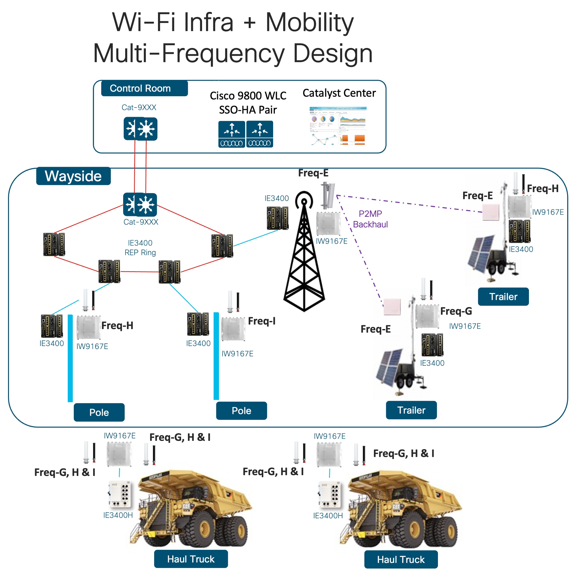 |
Table 8. Autonomous Haulage Greenfield Non-IRCM Components
| Component Role |
Platform or Device |
Function in This Architecture |
Deployment Notes |
| Wireless Controller |
Catalyst 9800 WLC |
Provides the single-controller policy, mobility, and multicast domain |
Target the controller size to fleet, AP, multicast, and growth expectations |
| Infrastructure AP |
IW9167E |
Provides engineered haulage coverage and overlap behavior |
Use the preferred steady-state AP for Greenfield haulage design |
| Vehicle Radio |
IW9167E WGB |
Provides the mobile machine transport edge |
Supports WPA2-FT-PSK where fast roaming is required |
| Distribution Switching |
IE9300 |
Aggregates industrial wireless infrastructure into the OT network |
Recommended distribution role for ruggedized aggregation and deterministic queueing |
| Access / Trailer / Vehicle Switching |
Cisco IE3100 / IE3100H / IE3400 / IE3400H / IE3500 / IE3500H |
Provides local wired attachment according to site need |
Final switch choice should follow Cisco industrial Ethernet platform-selection guidance rather than a single fixed SKU |
Tele-Remote Control Wi-Fi Use-Case Architecture
Scenario: This is the Greenfield Tele-Remote Control Wi-Fi architecture. The URWB architecture for this use case will be covered in a later chapter. Catalyst 9800 WLCs, IW9167E infrastructure APs, and IW9167E WGBs are deployed for Tele-Remote Control workflows on 5 GHz.
Use this when:the site is deploying a new Tele-Remote Control wireless architecture, or when the Tele-Remote Control area can be designed as a target-state environment using Catalyst 9800 WLCs, IW9167E infrastructure APs, and IW9167E WGBs.
Design constraints:
● Protect the control path first, then keep video stable enough for the operator to work safely and effectively.
● Design for deterministic 5 GHz behavior under machine motion, interference, changing line of sight, and production traffic load.
● Treat multicast-direct behavior, data-rate policy, and QoS design as core parts of the Tele-Remote Control architecture.
● Do not optimize only for peak throughput or a broad RSSI heat map. A Tele-Remote Control operator cares about usable video and stable control, so RF and QoS choices must follow the actual operator workflow.
● Document where the operator station sits relative to the wireless edge, which applications are local versus remote, and what backhaul path the control, video, and telemetry streams follow.
● Preserve segmentation and QoS treatment from the Wi-Fi edge through the OT backhaul and distribution layer.
Design Risk:treating Tele-Remote Control as a generic wireless coverage problem.
Tele-Remote Control performance problems are often blamed on the wireless link when the end-to-end path has not been documented well enough to separate wireless delay, application placement, backhaul delay, QoS treatment, or multicast handling.
Validation evidence:
● Production-representative testing of control, video, and telemetry traffic under machine motion.
● RF validation for the Tele-Remote Control operating zone, including AP candidate quality, roaming behavior, interference, and 5 GHz channel behavior.
● QoS validation across the wireless, switching, distribution, and OT backhaul path.
● Multicast-direct validation for the actual video and application flows used by the operator workflow.
● Documentation showing where the operator workflow terminates and how control, video, and telemetry traffic traverse the network.
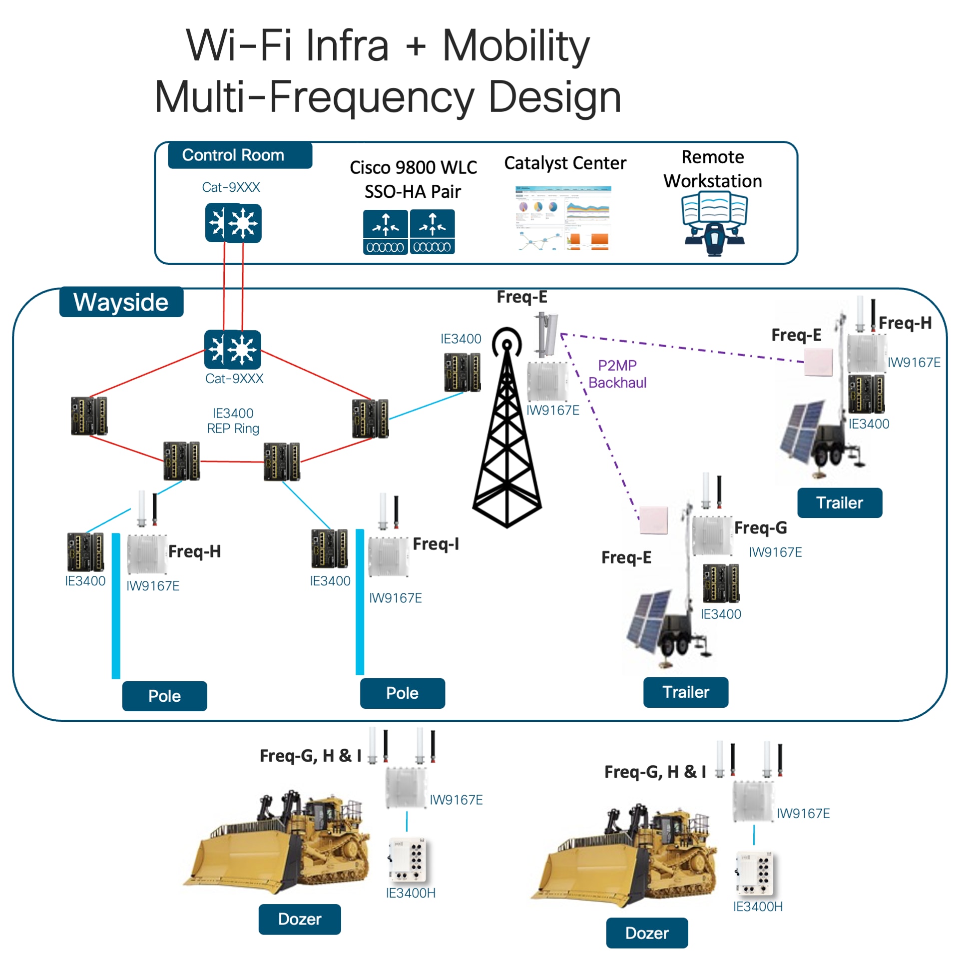 |
Table 9. Tele-Remote Control Wi-Fi Greenfield Components
| Component Role |
Platform or Device |
Function in This Architecture |
Deployment Notes |
| Wireless Controller |
Catalyst 9800 WLC |
Provides the centralized Wi-Fi control, policy, and QoS domain for Tele-Remote Control operations |
Design for 5 GHz Tele-Remote Control behavior, multicast-direct treatment, and controller resilience |
| Infrastructure AP |
IW9167E |
Provides engineered 5 GHz Tele-Remote Control coverage in the operating zone |
AP placement must optimize usable control and video behavior rather than generic area coverage |
| Vehicle Radio |
IW9167E WGB |
Provides the vehicle-side wireless edge for Tele-Remote Control, video, and telemetry |
Validate WGB placement, scan behavior, and QoS treatment under representative machine motion |
| Operator / Backhaul Path |
Site-specific operator station and OT backhaul attachment |
Carries control, video, and telemetry between the machine and the operator workflow |
Document where the operator workflow terminates so wireless delay is not confused with upstream application or wired backhaul delay |
| Distribution Attachment |
IE9300 distribution or approved OT aggregation |
Preserves segmentation and QoS from the Wi-Fi edge back into the OT network |
The wired design must maintain the same service objective as the wireless edge under load |
Wi-Fi RF and Mobility Design Principles
Engineer Wi-Fi coverage and mobility around the operating route, not around generic blanket coverage. In above-ground mining, the RF design succeeds only when the machine keeps usable control, telemetry, and video behavior through the real haul path, speed, geometry, and coexistence state of the site.
Treat overlap, antenna pattern, elevation change, and controller-domain boundaries as first-order design inputs. Wi-Fi mobility in mining is governed by environment layout, antenna coverage, and validated client behavior, not by enabling every roaming feature and hoping the platform chooses correctly at runtime.
Wi-Fi Frequency Design: 2.4 GHz and 5 GHz
This comparison applies to Wi-Fi frequency design only. URWB frequency architecture is addressed separately in Section 5 and should not be interpreted as support for 2.4 GHz URWB operation.
For Wi-Fi, the 2.4 GHz versus 5 GHz decision is a route-engineering choice. The correct band depends on route length, vehicle density, traffic profile, reuse requirement, available spectrum, antenna geometry, and the acceptance criteria for the machine workflow.
Table 10. Wi-Fi Frequency Design Comparison
| Design Dimension |
2.4 GHz Wi-Fi Design |
5 GHz Wi-Fi Design |
Mining Design Implication |
| Reach and edge behavior |
Longer practical reach and better tolerance at route edges when traffic demand is modest. |
Shorter practical reach that requires tighter AP placement, overlap design, and link-budget discipline. |
Use measured route behavior, not nominal coverage distance, to decide the band. |
| Capacity and reuse |
Limited channel count and higher co-channel reuse risk as corridors or fleets grow. |
More channel options and better reuse potential for dense routes, Tele-Remote Control zones, and higher-capacity traffic. |
Choose 5 GHz when the reuse plan and capacity target are the controlling constraints. |
| Channel width |
Use 20 MHz as the normal mining baseline. |
Start with 20 MHz; use 40 MHz only when validation shows enough spectrum cleanliness and margin. |
Avoid wider channels unless the route can hold them under motion and load. |
| Mobility and overlap |
Larger cells can improve continuity but can also create sticky-client behavior and uncontrolled overlap. |
Smaller cells can improve reuse but demand more precise handoff zones and WGB scan-list discipline. |
Validate roaming at production speed through the actual route, not only from a static survey. |
| Best-fit Wi-Fi use cases |
Autonomous Haulage or brownfield routes where reach, continuity, and lower-rate control or telemetry dominate. |
Tele-Remote Control Wi-Fi, denser operating zones, or haul routes that need more capacity and cleaner reuse boundaries. |
Use case, traffic profile, haul road and work-area layout and coverage requirements should drive band choice. |
| Configuration emphasis |
Conservative supported rates, documented channel set, route-specific WGB scan list, and rate or MCS limits from the weakest accepted route segment. |
Explicit channel plan, DFS decision, power and overlap control, route-specific WGB scan list, and rate or MCS limits from validated SNR. |
AP and WGB settings must be designed as a matched pair. |
| Validation focus |
Route-edge RSSI, SNR, retries, packet loss, roam stability, and client stickiness. |
SNR margin, airtime utilization, retries, roaming under motion, DFS behavior where used, and video/control headroom. |
Acceptance testing must prove the selected band under real machine speed and traffic load. |
Document the final band choice with the matching AP channel plan, channel width, supported-rate policy, transmit-power target, WGB scan list, and route-validation evidence. Mixing 2.4 GHz and 5 GHz assumptions across route segments makes later troubleshooting harder and can hide whether the issue is RF design, WGB behavior, or application demand.
Design AP placement and overlap around the actual haul route, loading approach, dump exit, and transition point. The route needs enough usable overlap to complete the roam cleanly, but not so much uncontrolled overlap that the WGB stays indecisive across a long stretch of road.
Validate corridor behavior with representative machine speed, antenna posture, and traffic load. A route that looks covered on a heat map can still fail operationally if the overlap zone is too narrow, too wide, or aligned to the wrong machine path.
● Use route-based overlap rather than area-based overlap as the primary Wi-Fi design method.
● Revalidate overlap whenever pit geometry, bench progression, or traffic path changes materially.
Brownfield IRCM Mobility Caveat
Do not mesh RAP to MAP between controllers in the Autonomous Haulage IRCM path. That adds avoidable cross-controller dependency to the exact part of the route that already carries the most migration risk.
Keep the IRCM overlap corridor narrow, explicit, and fully documented. The machine should cross the controller boundary only where the route was engineered and validated to do so.
● Inspect controller-domain behavior before retuning RF when the problem appears only at the migration corridor.
● Document where the old domain ends, where the new domain begins, and which vehicles are expected to traverse that overlap.
Keep one approved Wi-Fi diagram set that shows topology, roam behavior, traffic path, and validation scope for the mining use case. Operations, commissioning, and troubleshooting should all point back to the same figure set.
Use the diagram package to make the approved route, controller domain, QoS boundary, and antenna intent obvious. If the route design, controller design, and validation plan do not match the diagrams, the site is already drifting from the design record.
Common Wi-Fi Configuration Guidance
Use this section for the Wi-Fi configuration guidance that is common to both Autonomous Haulage and Tele-Remote Control.
The WLC baseline defines the controller-side settings that both Autonomous Haulage and Tele-Remote Control depend on before use-case-specific tuning is applied.
Use the tables in this section as a configuration checklist for production vehicle WLANs.
| Setting |
Baseline decision |
Design note |
| SSID name |
Create the production SSID |
Use a clear route or service name that distinguishes Autonomous Haulage, Tele-Remote Control, commissioning, and maintenance WLANs. |
| WLAN state |
Enable after design approval |
Enable only after the policy profile, tags, VLANs, security, multicast, QoS, and route acceptance records are ready. |
| Broadcast SSID |
Enable |
Broadcast the production SSID unless the customer has a tested interoperability reason to hide it. Hidden SSIDs do not provide meaningful security. |
| Frequency / Radio Policy |
Select intentionally |
For 2.4 GHz, do not use B/G; use G-only behavior. For 5 GHz, select the correct radio slot for the AP and route design. |
| Layer 2 Security |
Select the approved security method |
Use the Layer 2 security method validated for the design, such as WPA2-PSK, FT-PSK where supported, or 802.1X where Cisco ISE is part of the workflow. IW3702 does NOT support 802.11r/FT |
| CCX Aironet IE |
Enabled |
Required for a WGB to connect to the WLAN. |
| Coverage Hole Detection |
Disable |
Do not let coverage-hole behavior retune a route-based mining WLAN without a planned change and route revalidation. |
| P2P blocking action |
Normally Disabled |
Leave disabled unless the application requires a client-to-client communication. |
| Multicast Buffer |
Disable |
Disable multicast buffering for production vehicle WLANs. |
| Media Stream Multicast-direct |
Enable when multicast is used |
Enable for reliable multicast behavior so multicast is converted to unicast and can use retransmission when packets are lost. |
| Latency Measurement Announcements |
Enable |
Logs the time it takes for a wireless client to roam and re-authenticate as it moves between APs in a mobility group |
| Load Balancing |
Disable |
Do not let the controller move vehicle clients away from the engineered route candidate list. |
| Band Select |
Disable |
Do not steer production vehicle clients between bands automatically. |
| WMM policy |
Allowed |
Allow WMM so marked control, video, telemetry, and management traffic can map to the correct wireless access category. |
| 802.11k and 802.11v |
Disabled |
Do not use in directional, sectorized, or high-elevation-change mining roaming environments unless route testing proves the neighbor behavior helps rather than misleads the WGB. |
| Setting |
Baseline decision |
Design note |
| Profile Name and State |
Create, Name, and Enable |
Use a name that can be traced from the policy tag, WLAN, route, and use case. Enable only after the service policy is complete. |
| Passive client |
Enable |
Enable for WGB WLANs so quiet downstream wired endpoints can remain visible behind the WGB. |
| IP MAC binding |
Disable |
Disable for this design to avoid binding behavior that can conflict with WGB-connected endpoint behavior. |
| WLAN Switching Policy |
Central Switching Enabled |
Central switching drops traffic at the controller rather than at the infrastructure AP switch port and is the normal recommendation for this design. |
| VLAN |
Assign the WGB VLAN |
Select the VLAN that WGBs join and use for their controller-side attachment. This does not have to match client VLAN behind the WGB. |
| QoS policy |
Configure Auto QoS and SSID QoS policy |
Preserve the end-to-end service model for control, video, telemetry, and management traffic. |
| Mobility Anchors / Static IP Mobility |
Do not enable |
Leave Export Anchor unchecked and Static IP Mobility disabled. Do not configure static anchors for production vehicle WLANs; allow controller auto-anchoring behavior where controller mobility is required. |
| Idle Timeout |
Set high |
Use the highest value allowed by site policy. Timer expiry will force reauthentication while a vehicle is in production use. |
| Session Timeout |
Set high |
Set longer than a typical workday when policy allows to avoid reauthentication during operation. |
| Client Exclusion Timeout |
Disable unless required |
Disable unless the site security policy requires exclusion. If enabled, define recovery so a production vehicle is not stranded. |
| DHCP Required |
Disable |
WGBs are usually statically addressed. Do not require DHCP unless the site addressing model depends on it. |
| AAA override |
Disable unless Cisco ISE assigns policy |
Enable only when Cisco ISE is authenticating clients and assigning VLAN or policy dynamically. |
| Broadcast Tagging |
Enable |
When enabled, it forces the WLC to tag broadcast and multicast packets with the correct client MAC address, which is critical for WGB networks forwarding downstream traffic to connected devices. |
| WGB VLAN |
Enable |
Enable when VLANs behind the WGB must be carried through the WGB and mapped correctly into the controller policy. |
| ARP proxy |
Disable |
Pass ARP upstream through the network rather than having the wireless infrastructure proxy it. |
| Setting |
Baseline decision |
Design note |
| Policy Tag Name |
Create per route, use case, or operating area |
Use a name that identifies the production service and assignment scope. |
| WLAN-to-policy-profile mapping |
Map explicitly |
Bind each production WLAN to the correct policy profile. This is where the WLANs and policy profiles are applied together and then used later to apply to an infrastructure AP. |
| Setting |
Baseline decision |
Design note |
| Site Tag Name |
Create per route, site, or controller domain |
Use a name that operators can associate with the APs serving the route or work area. |
| Enable Local Site |
Normally Enabled |
Enabled Local Site sends traffic back to the controller under the central switching model. |
| FlexConnect / Local Switching posture |
Use only when intentionally required |
Disabling Local Site changes behavior toward FlexConnect/Local Switching, where client traffic can drop at the infrastructure AP switch port instead of returning to the controller. Use only with a deliberate design. |
| Setting |
Baseline decision |
Design note |
| RF tag name |
Create per RF role, route type, or AP use case |
Use separate RF tags when different AP groups need different radio behavior, such as Autonomous Haulage, Tele-Remote Control, point-to-point backhaul, point-to-multipoint coverage, or brownfield migration areas. |
| 2.4 GHz slot assignment |
Assign the correct RF profile to the 2.4 GHz radio slot |
Use only where the design intentionally uses 2.4 GHz, such as brownfield support, range-driven Autonomous Haulage, or client capability constraints. |
| 5 GHz slot assignment |
Assign the correct RF profile to the 5 GHz radio slot |
Use for Tele-Remote Control, higher-capacity client service, or other validated 5 GHz route designs. |
| Mixed radio roles |
Use separate RF tags when AP radio roles differ |
An AP used for point-to-point or backhaul on one radio and client service on another may need a different RF tag than an AP serving only vehicle clients. |
| Assignment scope |
Apply to the correct AP group, route, or work area |
The RF tag should match the physical AP role and antenna design. Do not reuse one RF tag across dissimilar route geometries or radio roles just because the AP model is the same. |
| Setting |
Baseline decision |
Design note |
| Band |
Set per route design |
Separate 2.4 GHz and 5 GHz behavior where the use case or brownfield migration requires it. |
| Data rates |
Set from route validation |
Use rates the route can sustain under motion, not rates that only work near the AP. |
| Mandatory and supported rates |
Align with WGB profile |
Keep management, roaming, and data behavior predictable across AP and WGB settings. |
| Channel width |
Set from capacity and reuse plan |
Use 20 MHz for difficult RF or maximum reuse, 40 MHz as a balanced point, and 80 MHz only where short distance and clean spectrum justify it. |
| TPC and DCA posture |
Constrain or disable for engineered routes |
Do not allow autonomous power or channel changes to invalidate a validated route plan. |
| Coverage hole detection |
Disable unless validated |
Disable for production route WLANs unless testing proves it helps and does not create instability. |
| Setting |
Baseline decision |
Design note |
| Radio profile name |
Create per radio role where used |
Use names that indicate band, route, and intended service behavior. |
| Band and slot role |
Set from physical AP design |
Align the radio profile with the AP slot and antenna design used on the route. |
| Allowed channel set |
Constrain to engineered channels |
Keep the channel list limited to the channels in the approved route plan. |
| Power assumptions |
Set from link budget and overlap plan |
Do not use maximum power as the default assumption. |
| Setting |
Baseline decision |
Design note |
| 2.4 GHz network |
Enable only where required |
Use for Autonomous Haulage where brownfield support, range, or client capability requires it. |
| 5 GHz network |
Enable where validated |
Use for Tele-Remote Control and capacity-focused designs where the coverage area, channel reuse plan, and client support are validated. |
| Radio network state |
Keep stable after acceptance |
Do not change global radio state without route revalidation. |
| Setting |
Baseline decision |
Design note |
| Global data rates |
Align with RF profile |
Do not leave global rates inconsistent with the RF profile and WGB rate set. |
| Global channel list |
Constrain where used |
Use only channels that belong to the engineered plan. |
| Global power limits |
Set from regulatory and route design |
Preserve EIRP and overlap assumptions documented for the route. |
| Client density or general radio parameters |
Use default unless justified |
Change only when tied to measured vehicle density, airtime behavior, or acceptance evidence. |
| Setting |
Baseline decision |
Design note |
| 802.11n/ac/ax posture |
Enable only where client and route support it |
Do not assume a higher capability helps if the WGB, channel width, or route SNR cannot sustain it. |
| A-MPDU |
Tune from latency and airtime goals |
Aggregation improves airtime efficiency but can affect latency behavior for control and video. |
| Guard interval / MCS / NSS behavior |
Set from validated route behavior |
Keep MCS and spatial-stream assumptions aligned with antenna count, SNR, and WGB capability. |
| Setting |
Baseline decision |
Design note |
| Media behavior |
Align with Media Stream design |
Do not enable media optimizations without matching Wireless Media Stream and Services multicast/QoS settings. |
| Latency-sensitive treatment |
Enable only where validated |
Tie media settings to measured application traffic and acceptance criteria. |
| Setting |
Baseline decision |
Design note |
| DCA |
Disable |
Do not allow dynamic channel assignment to change an accepted route plan. |
| TPC |
Disable |
Do not allow transmit power changes to alter engineered overlap or roam boundaries. |
| Coverage Hole Detection |
Disable |
Avoid controller-driven changes that can mask RF design issues or create route instability. |
| Event-driven RRM |
Do not use for production route WLANs unless validated |
Production channel and power changes should be handled through change control and route revalidation. |
| Setting |
Baseline decision |
Design note |
| Global wireless state |
Enable only accepted production behavior |
Keep global wireless behavior stable after route acceptance. |
| Global client steering features |
Disable for vehicle WLANs |
Do not use controller steering that conflicts with engineered route roaming. |
| Global defaults |
Leave default unless justified |
Change only where the setting is tied to a production vehicle WLAN requirement. |
| Setting |
Baseline decision |
Design note |
| Mobility domain |
Document explicitly where used |
Record the mobility domain for production controllers and route areas. |
| Mobility peers |
Configure only where migration requires it |
Use only for brownfield IRCM, inter-controller roaming, or controller interworking designs. |
| Auto-anchoring behavior |
Use where controller mobility requires it |
Do not configure static anchors in the policy profile; let the controller mobility design handle roaming behavior for the migration scenario. |
| Mobility evidence |
Required for migration |
Capture tunnel state, client event history, and route-level roam evidence where mobility is part of the design. |
| Setting |
Baseline decision |
Design note |
| Media Stream state |
Enable where multicast video/control requires reliability |
Use when the application requires multicast-to-unicast conversion and reliable delivery behavior. |
| Stream group |
Set from application flow list |
Use the actual multicast groups used by the production application. |
| Average packet size and bandwidth |
Set from measured or supplied values |
Mark values as planning assumptions if measured customer values are not available. |
| Admission and violation behavior |
Set from service priority |
Choose behavior that protects control and usable video without starving other required traffic. |
| Setting |
Baseline decision |
Design note |
| Global wireless multicast |
Enable where required |
Enable where Autonomous Haulage or Tele-Remote Control applications require multicast delivery. Validate wired multicast and WLC multicast settings together. |
| IGMP snooping / multicast control |
Enable where multicast is required |
Align controller multicast behavior with the wired multicast domain, querier placement, and application flow list. |
| Wireless broadcast and non-IP multicast |
Conditional |
Enable only for VLANs and protocols that require it. Keep unnecessary broadcast and multicast traffic out of production WLANs. |
| Multicast Direct relationship |
Align with Wireless Media Stream |
Confirm multicast service behavior matches the Wireless Media Stream settings for reliable multicast. |
| Setting |
Baseline decision |
Design note |
| WLAN QoS profile |
Use high-priority service |
Use Platinum or an equivalent validated QoS profile for production control and video WLANs, then verify end-to-end trust and queue mapping. |
| Outer QoS and SSID QoS policy |
Configure in policy profile |
Preserve markings between WGB, AP, controller, and wired OT network. |
| Multicast QoS profile |
Set from application priority |
Preserve or apply QoS markings during multicast-to-unicast conversion so control and usable video do not collapse into best effort. |
| AVC / NBAR visibility |
Optional |
Use for assurance or classification only when it supplements, rather than replaces, the end-to-end QoS trust model. |
Infrastructure AP Configuration Guidance
The infrastructure AP is the fixed side of the wireless path that the vehicle WGB depends on while the machine is moving. Its RF profile, channel plan, power level, antenna system, multicast behavior, and QoS treatment define the service envelope for Autonomous Haulage and Tele-Remote Control traffic.
Use the AP configuration to document the accepted route design. The settings below should be chosen from the haul road or work-area layout, application requirement, antenna design, WGB profile, and validated traffic model rather than copied from a generic AP template or maximum platform capability.
Infrastructure AP Baseline Decisions
| Setting |
Baseline Decision |
Design Guidance |
| Band Selection |
Set From Route Design |
Choose the band from the actual route and client population. 2.4 GHz can be appropriate where reach, brownfield support, or client capability matters more than capacity. 5 GHz is appropriate where the coverage area, spectrum reuse plan, and application throughput justify it. Do not assume one band is the mining default. |
| Channel Plan |
Engineer Explicitly |
Use only channels that belong to the validated route plan. The plan should account for adjacent route segments, AP overlap, channel reuse, expected interference, and migration areas. After acceptance, avoid unmanaged channel changes that make RF faults look like application or WGB faults. |
| DFS Channels |
Use Only Where Validated |
Avoid DFS channels where a radar event or forced channel move would interrupt production control traffic. Use them only when the local spectrum plan requires the channels and the operational risk has been accepted. |
| Channel Width |
Use The Narrowest Validated Width |
Choose the narrowest channel that can carry the validated application load with margin. Wider channels increase peak throughput, but they consume more spectrum, reduce channel reuse, raise the effective noise floor, and can make long-distance stability harder. |
| Transmit Power |
Set From Link Budget |
Set power from the route link budget, antenna gain, mounting height, overlap target, and regulatory EIRP limit. Maximum AP power is rarely the correct default because it can extend cells beyond the intended boundary and increase co-channel interference. |
| Supported Data Rates |
Align With WGB Rate Set |
Use rates the route can hold under motion, not rates that only work near the AP. Keep AP-supported rates aligned with the WGB rate set so management, roaming, and data behavior remain predictable through grade changes, curves, dust, and antenna transitions. |
| Antenna Type |
Match Radio Role |
Select the antenna pattern from the corridor shape, work area, mounting location, and radio purpose. A radio serving vehicle clients has different requirements than a radio used for a point-to-point link, point-to-multipoint segment, or Tele-Remote Control coverage area. |
| Antenna Orientation |
Set From Physical Survey |
Aim the antenna system for the intended haul road, working face, pit ramp, or Tele-Remote Control zone. Orientation is part of the RF design, not an installation detail to tune independently after the controller configuration is accepted. |
| Antenna Gain |
Document In RF Plan |
Document gain values with the route design and keep them aligned with EIRP, overlap, and regulatory assumptions. If the antenna is changed, recheck transmit power and coverage assumptions before treating the AP as accepted. |
| Multicast Direct |
Enable Where Required |
Enable where reliable multicast behavior is required by the production application. Use this deliberately with the controller multicast and media-stream design so the AP behavior matches the application service model. |
| Media Stream |
Enable Where Used |
Enable only for validated media or control traffic that depends on media-stream behavior. Leave unrelated defaults unchanged so troubleshooting remains focused on the production traffic classes that actually use the feature. |
| QoS Queue Treatment |
Align With Traffic Classes |
Preserve intended treatment for control, video, telemetry, and best-effort traffic across the wireless and wired path. The AP-side behavior should match the WLC policy, switch trust boundary, and application marking model. |
| WGB Alignment |
Validate With Vehicle Profile |
Treat the AP and WGB as one RF contract. Recheck the AP baseline whenever the WGB rate set, scan list, roaming model, VLAN behavior, or machine traffic model changes. |
| Channel Width |
Design Guidance |
| 20 MHz |
Use for difficult RF, longer links, dense channel reuse, or routes where margin and stability matter more than peak throughput. This is often the safest starting point when the environment is noisy or the route needs predictable reuse. |
| 40 MHz |
Use when the route needs more capacity and has enough signal quality and spectrum to preserve stable reuse. This is the usual balance point when throughput matters but the design still has to support route-scale mobility. |
| 80 MHz |
Use only for shorter, cleaner links where the throughput requirement justifies the spectrum cost. Avoid using 80 MHz as a default for long haul roads or areas where reuse, interference, or distance is the limiting factor. |
After the route is accepted, treat changes to AP channel width, power, antenna configuration, supported rates, multicast behavior, or WGB alignment as RF design changes. Revalidate the affected route before treating the new AP baseline as stable for Autonomous Haulage or Tele-Remote Control operation.
Vehicle WGB Configuration Guidance
The vehicle WGB is where the mobile RF path, downstream vehicle LAN, and application queue treatment meet. Because of this, the WGB profile has more tuning points than the infrastructure side. The purpose of this section is not to prescribe every command, but to identify the WGB parameters that usually matter in an above-ground mining design, what each parameter changes, and when the parameter should be adjusted.
Treat the WGB configuration as one coordinated vehicle profile. Uplink role, auxiliary radio behavior, roaming triggers, scan list, supported rates, MCS limits, antenna settings, transmit power, QoS behavior, RTS/CTS, retry behavior, and Ethernet-side behavior should be reviewed together whenever the route design, channel plan, antenna installation, or application mix changes.
Radio Role and Auxiliary Scan Behavior
| Parameter |
What It Changes |
Mining Design Guidance |
| Serving WGB radio |
Defines which radio carries the production uplink to the infrastructure AP. |
Use one radio as the serving uplink so the production path stays deterministic. Match this radio to the validated band, channel plan, antenna path, and power model. |
| Auxiliary radio scan-only role |
Allows the second radio to improve AP discovery without carrying production traffic. |
Use when the second radio is useful for discovery but does not have the antenna placement, cable path, or RF exposure required to be a production uplink. |
| Auxiliary radio scan-handoff role |
Allows the second radio to become a real uplink candidate during handoff. |
Use only when both radios are engineered well enough to carry production traffic, including antenna pattern, mounting location, cable routing, and RF exposure. |
Roaming Trigger and Scan Controls
| Parameter |
What It Changes |
When to Adjust |
| Signal threshold |
Sets how weak the serving AP signal can become before the WGB starts looking for a better candidate. |
Tune from measured route behavior. Aggressive values can help fast movement through clean overlap, but can also make the WGB chase short fades from berms, turns, articulation, dust, or grade changes. |
| Trigger period |
Sets how long the degraded signal condition must persist before roaming logic advances. |
Shorten only when the route has clean overlap and needs faster reaction. Lengthen when brief fades are common and the current AP remains serviceable. |
| Aux scan delta RSSI - same parent |
Sets how much better a candidate must be before the WGB treats a same-parent candidate as worth roaming to. |
Use to prevent unnecessary roaming when the candidate AP is only marginally better than the current AP. Keep values consistent across WGBs in the same mine area unless route evidence supports a different profile. |
| Aux scan delta RSSI - different parent |
Sets how much better a candidate must be before the WGB treats a different-parent candidate as worth roaming to. |
Use when the design needs stronger proof before moving between parent contexts. Validate against route logs so the WGB does not stay too long on a weakening AP. |
| Scan channel list |
Limits which channels the WGB scans for candidate APs. |
Include only the real infrastructure channels used on that route or work area. Do not leave the WGB scanning all channels. Update the list whenever the site channel plan changes. |
Join, Retry, and Timer Behavior
| Parameter |
What It Changes |
Mining Design Guidance |
| Association, authentication, and EAP timers |
Controls how patient the WGB is during join and reassociation exchanges. |
Change only when logs show valid join attempts failing too early on an otherwise valid RF path. Timer tuning does not fix poor overlap, poor antenna placement, or a weak candidate list. |
| Management retries |
Controls retry behavior for management exchanges during association and roaming. |
Tune from WGB logs and route behavior. Do not use retry changes as a substitute for correcting the RF path. |
| Packet retries |
Controls how many times the WGB retries a failed transmission before dropping it. |
Use a deliberate retry limit. For this mining profile, use 16 retries and drop after the retry limit so short RF disruptions get persistence without allowing failed traffic to accumulate indefinitely. |
Supported Rates and MCS Limits
Supported rates and MCS limits control the rate ladder the WGB is allowed to use. The objective is not to force the lowest or highest possible rate; it is to keep the WGB inside the range the route can sustain without excessive retries.
For initial validation, leave the MCS ranges enabled, drive the route under normal operating conditions, and review retry counters and rate history. RSSI and SNR confirm coverage, but retries show which MCS values are not holding. If higher MCS values create retry growth or repeated fallback, remove them and retest.
Treat MCS limits as a stability control, not a throughput target. A lower stable range is better than a higher range that only works near the AP.
| Configuration Area |
Design Guidance |
| Legacy basic/mandatory rates |
Keep legacy basic/mandatory rates aligned with the infrastructure APs. |
| HT, VHT, and HE MCS indexes |
Configure allowed HT, VHT, and HE MCS indexes per WGB radio slot. |
| MCS ceiling consistency |
Apply the same MCS ceiling across enabled HT, VHT, and HE profiles when they share the same validated design intent. |
| HE / 802.11ax behavior |
Use HE/802.11ax defaults unless validation shows a stability or application penalty. |
| Parameter |
What It Changes |
Mining Design Guidance |
| Antenna count |
Defines how many installed antenna paths the WGB is expected to use. |
Match the actual installation. Preserve diversity where the physical antenna design supports it, but do not configure antenna paths that are not installed or usable. |
| Spatial streams |
Defines how many transmit and receive streams the radio can use. |
Do not configure more spatial streams than the active antenna paths can support. A mismatch can create unstable rate behavior and misleading capacity assumptions. |
| Antenna gain |
Describes the installed antenna for link-budget and regulatory behavior. |
Set antenna gain to the actual installed antenna, not to the desired EIRP outcome. |
| Transmit power |
Controls WGB transmit power and affects link symmetry, overlap, retries, and roaming. |
Set from the route link budget and overlap plan. Maximum power is not a default mining best practice. |
| Encryption |
Defines the radio security posture used by the WGB association. |
Use AES as the baseline. Solve compatibility problems in the WLAN and client design rather than weakening the WGB radio posture. |
QoS, Video, and Airtime Behavior
| Parameter |
What It Changes |
Mining Design Guidance |
| Application marking |
Determines whether control, video, telemetry, and management traffic arrive at the WGB with usable QoS markings. |
Preserve correct markings when the source or vehicle switch marks traffic correctly. If marking is wrong, fix the trust boundary instead of expecting the radio to infer service intent. |
| Queue mapping |
Changes which over-the-air queue the WGB uses for selected traffic. |
Use only when the design can classify traffic consistently. Air-side queue mapping is not the same as end-to-end remarking unless the rest of the path preserves the same intent. |
| Optimized video profile |
Applies a preset radio profile intended for video behavior. |
Use for WGBs carrying validated video traffic when the preset matches the application mix. The selected profile can change based on available platform presets and validation results. |
| A-MPDU posture |
Balances aggregation efficiency against queueing delay. |
Less aggregation can reduce delay on critical queues, but it costs airtime efficiency. Tune with the queue model and do not disable aggregation everywhere as a generic fix. |
| Parameter |
What It Changes |
Mining Design Guidance |
| RTS/CTS state |
Enables or disables Request to Send / Clear to Send protection on the radio. |
Bias toward RTS/CTS when deterministic behavior matters more than peak throughput, especially on long-distance, hidden-node, or multi-vehicle routes. |
| RTS threshold |
Sets the frame-size threshold where RTS/CTS protection is used for over-the-air transmissions. |
If the threshold is too high, the traffic that needs protection may never use RTS/CTS. If it is too low, the design pays protection overhead for too much traffic. |
| Packet-size awareness |
Connects the threshold choice to the real control, telemetry, and video packet profile. |
Use packet captures or application documentation before choosing the value. Real-time video and control traffic should not be tuned from assumptions about packet size. |
Ethernet-Side and Bridge-Client Behavior
| Parameter |
What It Changes |
Mining Design Guidance |
| Ethernet port native VLAN |
Defines how untagged traffic received from the vehicle switch is associated with a VLAN on the WGB Ethernet side. |
Set the native VLAN to match the vehicle switch treatment of untagged traffic. A mismatch can create a vehicle LAN problem that looks like a wireless problem. |
| Broadcast tagging |
Controls whether broadcast traffic is handled with VLAN tagging on the wired side. |
Use only when the downstream VLAN design requires it. Do not enable it as a generic WGB default if the vehicle LAN does not expect that behavior. |
| Bridge-client timeout |
Controls how long the WGB retains downstream client information. |
Use a long, explicit timeout for stable onboard endpoint sets so valid clients do not age out too easily during short RF interruptions or route transitions. Keep the value consistent across WGBs in the same mine area unless the vehicle LAN model requires a different profile. |
Configuration Review Checklist
| Review Item |
Expected Outcome |
| Radio roles are explicit. |
The serving radio and auxiliary radio behavior are documented, and scan-handoff is used only when both radios are valid production uplink candidates. |
| Roaming parameters are route-based. |
Signal threshold, trigger period, same-parent delta RSSI, different-parent delta RSSI, packet retries, and scan list reflect measured route behavior. |
| Rate policy is per radio. |
Legacy rates, HT MCS, VHT MCS, and HE MCS limits are configured per WGB radio slot where both radios are used. |
| QoS behavior matches the application model. |
Video profile, queue mapping, A-MPDU, and RTS/CTS choices reinforce the same control/video priority model. |
| Ethernet-side behavior matches the vehicle LAN. |
Native VLAN, broadcast tagging, and bridge-client timeout align with the vehicle switch and onboard endpoint model. |
Vehicle Switch Configuration Guidance
The vehicle switch defines the wired trust boundary for the machine. Its configuration determines how onboard VLANs are carried toward the WGB, whether application markings are preserved or corrected, and whether control, video, telemetry, and management traffic remain distinguishable before they enter the wireless bridge path.
The switch-side LAN model should match the WGB Ethernet-side assumptions. If the native VLAN, tagged VLANs, broadcast behavior, QoS trust, or management path are not clearly aligned, the issue can appear to be wireless-related even when the actual mismatch is on the vehicle LAN.
| Area |
Guidance |
Common Issue to Avoid |
| VLAN model |
Define which onboard VLANs are carried toward the WGB and whether traffic is tagged or untagged on the WGB-facing port. |
Native-VLAN or trunk mismatch between the vehicle switch and WGB. |
| Broadcast behavior |
Keep broadcast tagging and forwarding behavior consistent with the VLAN model used toward the WGB. |
Broadcast traffic reaching the WGB differently than expected by the wireless design. |
| QoS trust |
Preserve DSCP or CoS markings when the source marks traffic correctly. |
Correctly marked traffic being reset or collapsed into a default class. |
| Remarking |
If the vehicle switch corrects markings, document it as the trust boundary for the machine LAN. |
Unclear ownership of where application traffic becomes classified. |
| Queue treatment |
Keep switch queue behavior aligned with the intended treatment of control, video, telemetry, and management traffic. |
Local switch queues flattening differentiated traffic before it reaches the WGB. |
| Management reachability |
Confirm the vehicle switch management path follows the intended onboard network design. |
Management access depending on an unintended VLAN or path. |
Before finalizing the vehicle switch configuration, verify that the native VLAN and tagged VLAN model align with the WGB, application markings are either preserved or intentionally corrected, and any remarking on the vehicle is documented as an explicit trust-boundary decision.
Infrastructure Switching Network Guidance
The infrastructure switching network must preserve the service model selected at the wireless edge. If QoS trust, segmentation, multicast handling, or routing treatment changes unexpectedly in the wired path, the wireless design can appear inconsistent even when the AP and WGB are configured correctly.
The switching design keeps control, usable video, telemetry, and management traffic in the correct relative order after traffic leaves the vehicle and wireless domain. Use the site switching standard for normal switch hardening and operations, then verify the wireless-specific checkpoints below
Infrastructure switching configuration checkpoints
| Area |
Infrastructure switch guidance |
| AP ports |
Central switching or tunnel: use an access port in the AP management VLAN. Local switching at the AP: use a trunk, set the AP management/native VLAN where required, and allow only the required client VLANs. |
| VLAN or routed path |
Carry the WLC, AP management, client, and application VLANs or routed paths required by the design. |
| QoS |
Preserve approved DSCP or CoS markings through AP access, controller attachment, and distribution. Keep control above video and avoid best-effort remarking. |
| Multicast |
Pass required multicast groups end to end. Align IGMP snooping, querier placement, multicast routing, and controller multicast behavior with the application flow list. |
| Management access |
Keep management access on the approved operational path and separate where the site design requires it. |
| Capacity headroom |
Size uplinks and queues for packet mix, retries, bursts, multicast overhead, and reserve capacity for route impairment. |
Monitoring and Configuration Guidance
Use Cisco Catalyst Center as the primary management and assurance workflow for the Wi-Fi design. Controller views remain important for detailed WLAN, mobility, and client validation, but the production operating record should be anchored in Catalyst Center Assurance, inventory, topology, and lifecycle views. The goal is one operating record for APs, WGBs, controllers, switching, route validation, assurance evidence, and change history.
Catalyst Center Assurance is the primary view for confirming that the deployed network continues to match the approved design intent. Use it to monitor device health, client experience, topology context, fault trends, and service-impacting changes across the Wi-Fi and switching environment. Controller-side views should be used to validate detailed WLAN behavior, mobility events, client state, and policy attachment when deeper wireless inspection is required.
For small pilots, controller views and direct device checks can be acceptable. Once the deployment becomes a production mining network, the site needs a repeatable operating record that ties configuration intent, Catalyst Center Assurance data, route evidence, commissioning evidence, and change history together. If the design cannot be understood from the management views and the design record together, the operational model is not clean enough yet.
Cisco Cyber Vision can complement this workflow by adding OT asset visibility and industrial-protocol context. It does not replace Catalyst Center Assurance, controller assurance, or configuration visibility. Use each platform for its intended role instead of expecting one tool to explain the entire network by itself.
Operating record and assurance evidence checkpoints
| Operating area |
Primary view |
Evidence to retain |
| Network inventory and topology |
Catalyst Center inventory and topology |
Controllers, APs, switches, WGB attachment points, site hierarchy, and route-relevant infrastructure |
| Assurance and health |
Catalyst Center Assurance |
Device health, client experience, fault trends, service-impacting events, and change correlation |
| WLAN and policy validation |
Catalyst Center and controller views |
WLAN baseline, policy profile attachment, QoS posture, multicast posture, and deployed configuration intent |
| Mobility and client behavior |
Controller mobility and client views |
WGB/client association state, roam events, mobility history, and client troubleshooting evidence |
| AP and WGB state |
Catalyst Center, controller views, and direct device checks where required |
AP radio state, WGB association behavior, scan assumptions, queue behavior, and accepted site-owned values |
| Commissioning evidence |
Catalyst Center exports, controller exports, screenshots, and design record |
Deployed WLAN baseline, AP/WGB state, queue model, route validation, and acceptance evidence |
| Change tracking |
Catalyst Center lifecycle/change views and site change record |
Changes tied to WLC profiles, AP/RF profiles, WGB profiles, switch policy, route evidence, and approval history |
| OT asset and protocol context |
Cisco Cyber Vision |
OT asset visibility and industrial-protocol context that complements, but does not replace, Wi-Fi assurance |
Autonomous Haulage Wi-Fi Deployment Guidance
Use this section for the Wi-Fi guidance that is unique to Autonomous Haulage. The common WLC, infrastructure AP, vehicle WGB, vehicle switch, infrastructure switching, and management guidance stays in Section 4.7. This section only calls out the places where haulage intentionally diverges from that common baseline.
Autonomous Haulage favors predictable machine movement and stable route behavior over aggressive mobility tuning. The design has to survive real haul roads, real overlap corridors, and real migration boundaries without pretending that legacy and target-state platforms behave the same way.
Before choosing haulage-specific values, record the haul-route distance, expected signal level at distance, bandwidth requirement by vehicle class, machine speed, typical movement pattern, obstruction points, controller domain boundaries, and target vehicles per infrastructure AP. Those inputs determine whether the common Wi-Fi configuration profile in Section 4.7 is realistic for the haul route.
Autonomous Haulage WLC Guidance
On Autonomous Haulage, the WLC should be kept as stable and predictable as possible. Use Catalyst 9800 with IW9167E infrastructure APs and IW9167E WGBs as the preferred steady-state design, and keep the SSID, security posture, policy baseline, and mobility model as uniform as the validated fleet allows.
Fast-roaming features and controller-side mobility assistance should be chosen from real client behavior, not from a generic assumption that every mobility feature improves a haul route. Long outdoor routes with sector transitions, elevation change, dust, and temporary obstruction usually want a more conservative mobility posture than a Tele-Remote Control work area.
● Use 802.11r or FT-PSK only where the validated client population actually supports it.
● Do not assume 802.11k or 802.11v help in directional, sectorized, or large-elevation-change haulage environments.
● Keep the Greenfield 9800 baseline explicit so later troubleshooting can distinguish baseline behavior from brownfield exceptions.
Autonomous Haulage Infrastructure AP Guidance
The Autonomous Haulage AP profile should be biased toward route stability before raw throughput. The infrastructure side is there to support long lines of travel, repeatable overlap, and predictable roam behavior under grade change and dust, not to chase the most aggressive RF settings the platform can expose.
Band choice is part of that decision. In haulage, 2.4 GHz can still be the better starting point when reach and steady telemetry behavior matter more than throughput, while 5 GHz is justified when the haul road layout, reuse requirement, and capacity target truly need it. Make the band decision from the real route and fleet behavior instead of defaulting to one answer for every corridor.
● Bias the AP design toward route stability before headline throughput.
● Choose band, channel width, and overlap from the actual haul road geometry, not from generic area coverage.
● Do not quietly inherit brownfield AP assumptions into the Greenfield target state such as output power.
Autonomous Haulage Vehicle WGB Guidance
Autonomous Haulage WGB behavior should be tuned for stable roaming and predictable route behavior, not for the fastest possible reaction to every short RF dip. A haul route usually wants the client to ignore harmless short fades from berms, turns, dust, or elevation change while still moving cleanly when the overlap corridor is engineered correctly.
Keep WGB-specific features explicit in the design record. Auxiliary-radio behavior, band selection, scan behavior, and supported roaming features should be called out instead of left as implied defaults. Bias the WGB mobility posture toward stable route behavior before aggressive roam response.
● Keep IW9167E WGB behavior separate from IW3702 behavior in the design record.
The following haul-truck examples are included as physical-installation references for vehicle-side radio placement, antenna separation, cable routing, and serviceability. Use them as placement guidance, not as legacy SKU prescriptions.
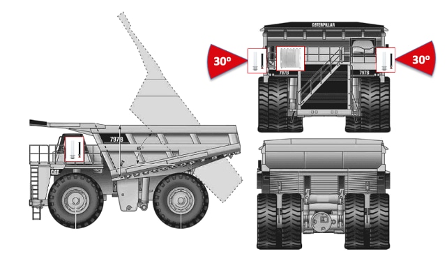
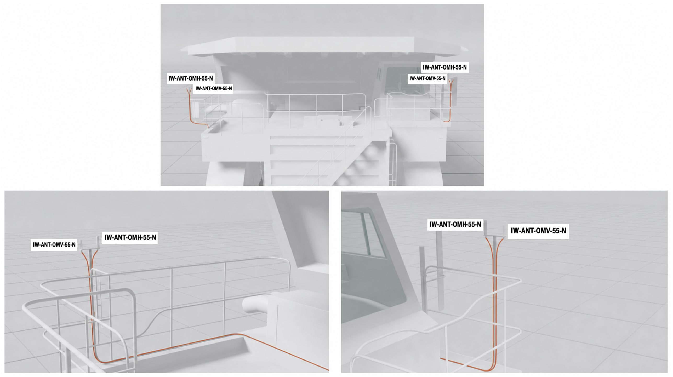
Light-utility-vehicle examples are useful for showing how a simpler single-radio installation can still preserve antenna height, cable protection, and service access.
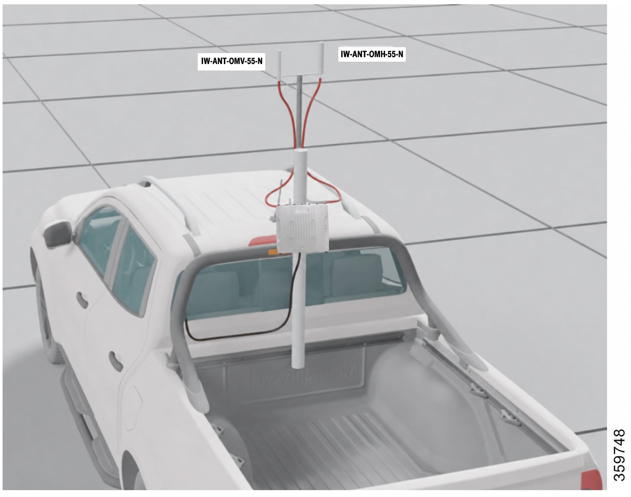
Brownfield IRCM WLC and Mobility-Tunnel Guidance
Treat Brownfield IRCM as a dual-controller migration design. The AireOS 5520 brownfield domain and the Catalyst 9800 target-state domain are joined by the mobility relationship and mobility tunnel required for the validated transition path.
Align the two controller domains by function, not by one-to-one feature mapping. The route still needs the same SSID intent, compatible security posture, compatible VLAN and policy attachment, aligned QoS and multicast treatment, and explicit visibility into the mobility-tunnel path even though AireOS and Catalyst 9800 express those functions differently.
Use this IRCM design as a migration path, not as the destination architecture. The target end state remains Catalyst 9800 with IW9167E infrastructure APs and IW9167E WGBs on the vehicles. Keep the IRCM overlap corridor, AireOS dependency, and mixed-client behavior visible so the site can retire them deliberately instead of normalizing them as the steady state.
Use the Cisco IRCM guidance directly when building this migration path: Overview of IRCM: https://www.cisco.com/c/en/us/td/docs/wireless/controller/9800/config-guide/ConfiguringIRCM/b-configuring-inter-release-controller-mobility-in-wireless-deployments-supporting-aireos-and-catalyst-9800-controllers/m-overview-of-ircm.html
and IRCM Support for Brownfield Deployments within Enterprise: https://www.cisco.com/c/en/us/td/docs/wireless/controller/9800/config-guide/ConfiguringIRCM/b-configuring-inter-release-controller-mobility-in-wireless-deployments-supporting-aireos-and-catalyst-9800-controllers/m-ircm-support-for-brownfield-deployments-within-enterprise.html
Do not configure guest-style mobility anchoring for this Autonomous Haulage IRCM design. Let the controllers determine the client traffic anchor from the client's initial association. In AireOS-to-Catalyst 9800 IRCM roaming, the client remains anchored to the first WLC it joins, so the initial join point must be part of the engineered migration design rather than treated as an afterthought.
● Engineer the controller-boundary overlap corridor as a production path, not as a temporary handoff zone.
● Follow the Cisco IRCM configuration guide closely or the client is likely to disconnect and reconnect instead of roaming cleanly between AireOS and Catalyst 9800.
● Inspect controller-to-controller policy mismatch and mobility-tunnel behavior before changing RF thresholds when the problem appears only at the coexistence corridor.
Brownfield Non-IRCM Migration Guidance
Treat Brownfield Non-IRCM as controlled coexistence, not as seamless cross-domain roaming. The two validated states are infrastructure-first migration with Catalyst 9800 and IW9167E infrastructure serving IW3702 clients, and vehicle-first migration with AireOS 5520 and 1572 or IW3702 infrastructure serving IW9167E WGBs.
Use this Non-IRCM brownfield design only as a controlled migration state as it is useful when controller, infrastructure, and vehicle refresh cannot happen at the same time, but it should still have a target exit plan toward the greenfield 9800 and IW9167E architecture.
Keep the vehicle inside the intended operating domain for that migration phase and validate the exact machine behavior at every boundary. Do not present the route as if unlike controller domains or unlike client-behavior domains will roam seamlessly when the design is intentionally not using IRCM.
● Validate infrastructure-first and vehicle-first states separately because they fail differently and create different support risks.
● Treat the migration boundary as a design constraint, not as an implementation detail.
AireOS 5520 Controller Considerations
AireOS 5520 should be called out explicitly in the Autonomous Haulage branch because its WLAN, mobility, QoS, and multicast semantics are not identical to Catalyst 9800 even when the design intent is the same. The brownfield path has to align those functions deliberately instead of assuming one controller's configuration language maps directly to the other.
Keep the AireOS configuration record explicit: WLAN and security model, mobility-peer state, VLAN and interface mapping, QoS treatment, multicast behavior, and the brownfield enterprise IRCM steps that make the coexistence corridor work. If those are not documented clearly, the migration state will drift and later troubleshooting will start from the wrong baseline.
● Call out AireOS-specific WLAN, mobility, QoS, multicast, and interface behavior as part of the brownfield design record.
● Do not assume Catalyst 9800 terminology or workflow applies directly to AireOS.
● Keep AireOS controller configuration visible anywhere the haul route still depends on it.
IW3702 Workgroup Bridge Considerations
IW3702 WGBs differ from the IW9167E WGBs in that they lack 802.11r support, they carry a different roaming model, and they do not expose the same feature or radio behavior set as the newer platform.
That means the brownfield haulage configuration has to keep the IW3702-specific baseline explicit. Band choice, supported rates, supported roaming features, and the overall client-behavior expectation should be written with the legacy client in mind instead of copied from the IW9167E profile and assumed to work.
● Do not assume FT-PSK or modern roaming behavior on IW3702 just because it exists on IW9167E.
● Keep IW3702 band, roaming, and security assumptions separate from IW9167E behavior in the design record.
● Validate legacy WGB routes with the actual IW3702 population, not with newer clients as stand-ins.
Autonomous Haulage Monitoring and Validation
Validate Autonomous Haulage Wi-Fi on the real route with the real machine workflow. The design is not accepted because the client stayed associated; it is accepted because the machine still behaved correctly through the approved path, overlap zones, and migration boundaries.
That means the operating record has to include the haul road or work-area layout, expected machine behavior, overlap corridor, controller domain, client population, packet-size assumptions, and acceptance criteria that the site is actually using to approve the deployment. Keep the management views and the design record aligned so later changes can be traced to the route outcome they affect.
Treat vehicle density as an engineered airtime result, not as a platform claim.
A route that looks fine on average can still fail when several vehicles burst at once or retry rates rise.
● Keep the validation record and the configuration record together so later changes can be traced to the route outcome they affect.
● Record routes, speeds, overlap corridors, AP candidates, migration boundaries, packet-size assumptions, vehicle-density assumptions, and acceptance criteria.
● Include retry factor, packet-size mix, burst behavior, and headroom explicitly in the haulage density model.
● If a site-owned value cannot be named and defended, it is not ready for production use.
● Autonomous Haulage validation should cover both steady-state and migration-state behavior where the site still depends on brownfield components.
Tele-Remote Control Wi-Fi Deployment Guidance
Use this section for the Wi-Fi deployment guidance that is unique to Tele-Remote Control. The common component-level configuration stays in Section 4.7. This section only calls out the places where Tele-Remote Control intentionally diverges from the common baseline.
Tele-Remote Control Wi-Fi is not Autonomous Haulage with more video.
It is a different service model. Protect control first, keep video usable, and leave enough RF and airtime margin for route degradation and traffic bursts.
Before choosing Tele-Remote Control-specific values, document the operating distance, required control and video KPI targets, codec and packet-size behavior, movement pattern, expected signal level at distance, obstruction points, and target number of vehicles per infrastructure AP. Tele-Remote Control Wi-Fi fails quickly when those inputs are guessed instead of measured.
Tele-Remote Control WLC Guidance
On Tele-Remote Control, the WLC must enforce the service model deliberately. Protect control first and make video usable, not perfect. That means the WLAN, policy, QoS trust, multicast-direct posture, Media Stream posture, and any controller-side remarking or tunneling behavior all have to support the same operator workflow instead of being tuned independently.
Tele-Remote Control usually wants a more aggressive and lower-latency bias than Autonomous Haulage, but that does not mean every controller feature should be turned up to its most aggressive setting. Choose the controller posture from the actual operator distance, codec mix, queue model, and trust boundary.
● Keep the queue path aligned from source application to controller, AP, WGB, switch, and OT path.
● If the design remarking point changes, document the new trust boundary explicitly.
● Validate control and video together. A good-looking video queue is not a success if the control loop becomes unstable.
Tele-Remote Control Infrastructure AP Guidance
The Tele-Remote Control AP profile should be engineered around the operator path rather than generic coverage success. Use 5 GHz and the AP-side choices for channel width, power, antenna role, rate caps, multicast-direct, and Media Stream all need to support predictable control and usable video under load.
This is where RF and queue behavior meet. If the AP side is tuned only for close-in throughput or broad blanket coverage, the operator workflow will usually fail first at work area edges, under burst traffic, or when retries rise.
Capacity planning should be based on airtime demand, not a simple count of machines multiplied by a nominal application rate. Additional active machines add payload load, but they also add contention, backoff, retry exposure, queueing delay, and multicast or unicast replication behavior. As the channel becomes busy, these effects compound, and usable Tele-Remote Control performance can degrade before raw channel utilization appears exhausted.
● Use channel width, rate caps, and power to support stability before headline throughput.
● Leave enough RF and airtime margin for retries, burst behavior, and partial impairment.
Tele-Remote Control Vehicle WGB Guidance
The Tele-Remote Control WGB profile usually needs a tighter and lower-latency bias than Autonomous Haulage. The vehicle should react earlier to degrading RF when the operator workflow justifies it, the scan list should stay tight, and the low-latency queue and aggregation posture has to be chosen from the actual control and video traffic rather than a generic mobility template.
That still has to be engineered, not guessed. A more aggressive WGB profile only helps when the AP placement, overlap, scan-list design, and packet-size profile support it. If the route is messy, aggressive scan or rate behavior will simply surface more instability sooner.
● Keep the scan list tight and route-specific.
● Use low-latency queue, A-MPDU, and RTS/CTS choices that match the real control and video packet profile.
● If the second radio can become the serving uplink, engineer it as a real uplink and not just as a scan helper.
Use dozer installation examples to validate antenna height, structure clearance, cable routing, and full-work-area coverage under pitch, roll, and frequent azimuth changes.
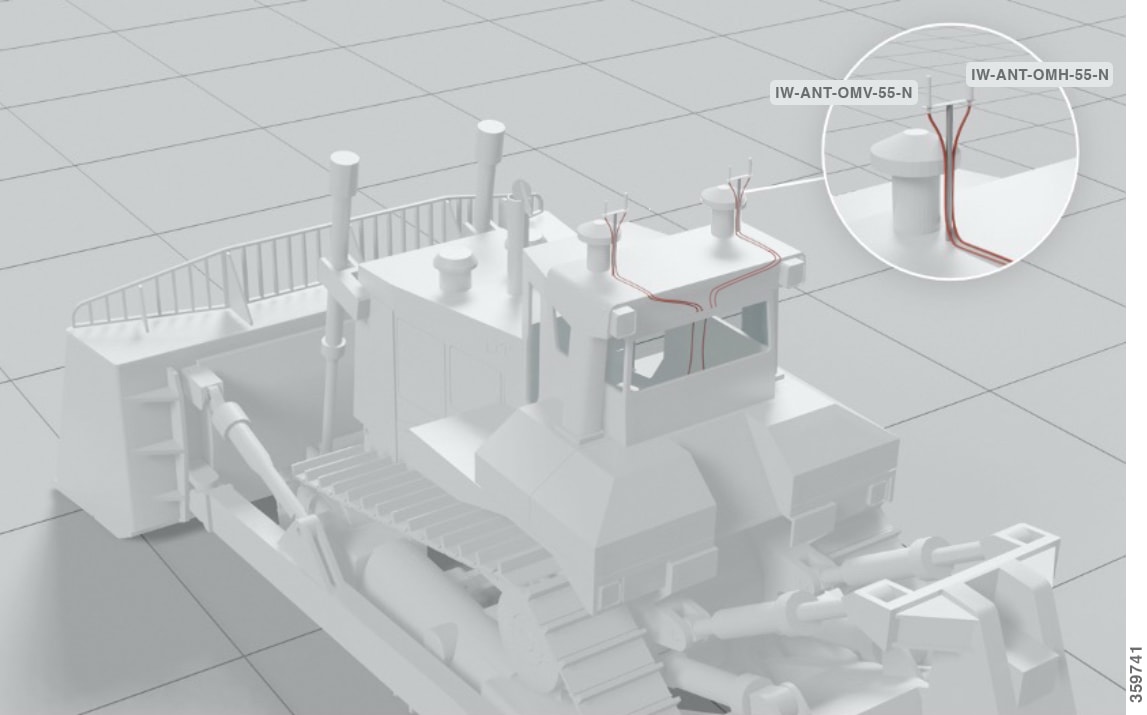
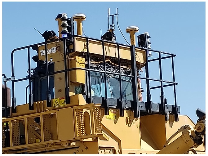
Drill installations should preserve full-machine coverage while keeping antennas clear of moving structure, ladders, and routine maintenance paths. Picture below shows mounting options. Two WGBs should not be placed on one drill.
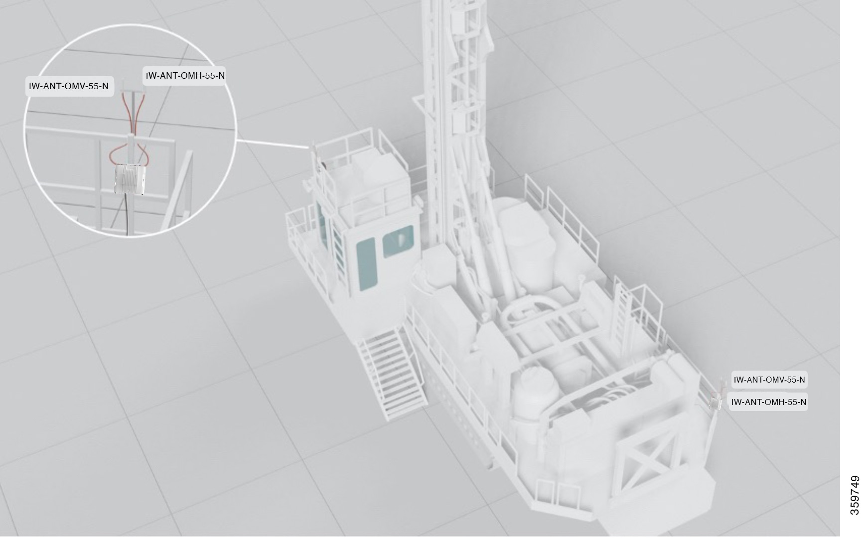
Tele-Remote Control Vehicle Switch Guidance
The vehicle switch must preserve the Tele-Remote Control queue model before traffic reaches the WGB. If the application is already marking correctly, preserve that marking. If it is not, decide deliberately whether the correction happens on the application side, the vehicle switch, or the WGB. Do not leave that trust boundary implied.
This matters more in Tele-Remote Control because the operator sees queue inconsistency quickly. If control, video, telemetry, and management collapse together on the vehicle, the wireless side cannot reliably recover that separation later.
● Preserve application markings when they are already correct.
● If the marking is fixed on the vehicle, document that as the trust boundary.
● Keep onboard VLAN, queue, and native-VLAN behavior aligned with the WGB profile.
Tele-Remote Control Infrastructure Switching Network Guidance
The infrastructure switching path must preserve the same service model chosen at the AP, WGB, and controller. If the wired OT path flattens the queues back into best effort, or changes trust behavior mid-path, the Tele-Remote Control design will look inconsistent even though the wireless edge is configured correctly.
Treat Tele-Remote Control capacity as an airtime and latency budget, not as a raw throughput number. Channel width, rate caps, retries, multicast handling, wired queue preservation, headroom, and burst behavior all matter because the operator workflow usually fails long before the path is formally out of bandwidth.
● Keep control above video while keeping video usable enough for the operator to work safely.
● Preserve the same queue and trust model through the wired OT path.
● Treat Tele-Remote Control vehicle density and headroom as site-owned calculations, not canned platform numbers.
Tele-Remote Control Validation
Accept the Tele-Remote Control Wi-Fi design only if the real operator workflow remains usable. Good RF counters do not matter if the control loop feels laggy or the video becomes unusable under load.
The validation record must capture the real route, the real codec mix, the real queue model, the actual headroom target, and the packet-size assumptions the site accepted. With those metrics properly documented, any design changes can be made accurately.
Tele-Remote Control validation should include both normal operation and impaired operation. Retries, video bursts, background traffic, multicast behavior, and partial obstruction all consume headroom. If the design only works when the route is quiet and the RF path is ideal, it is not ready for production.
● Validate control, video, and route behavior at the actual operating distance and through the same AP and queue path that production will use.
● Validate with the real codec mix, expected packet sizes, and realistic burst behavior.
● Record the headroom target and the accepted reserve for retries, impairment, and additional active vehicles.
● Record channel plan, band use, threshold values, packet-size assumptions, queue model, headroom target, and acceptance criteria before production.
● Keep the site-owned values and acceptance evidence with the design record.
Wi-Fi Operations, Monitoring, and Troubleshooting
Run the Wi-Fi design as an operational system, not as a one-time installation. The site needs visibility into controller domains, AP and WGB health, mobility events, queue treatment, and change history if it expects to maintain stable machine behavior over time.
Keep operations, troubleshooting, and change governance close to the deployment profile. Most recurring field problems are not mysterious; they are the result of RF drift, migration-state drift, queue inconsistency, undocumented configuration change, or a route condition that no longer matches the accepted design.
Catalyst Center and Controller Visibility
Use Catalyst Center as the primary management platform for the Wi-Fi design when the deployment moves beyond a simple pilot. It provides inventory, topology context, assurance visibility, lifecycle workflow, and a consistent operational record across controllers, APs, switches, and change events.
Controller views still matter. Use them to confirm mobility events, AP state, client state, multicast behavior, and tunnel behavior. The operational risk comes from running the site as a collection of disconnected screens and ad-hoc spreadsheets after the network becomes a production mining system.
For industrial operations context beyond the controller and assurance views, this CVD also references Cisco Catalyst Center for Industrial Automation. That document is useful when the site needs more detailed guidance on how Catalyst Center fits into an industrial networking operations model.
● Track controller, AP, WGB, and switch inventory against the approved software and hardware matrix.
● Use controller views for client state, mobility events, multicast behavior, policy attachment, and tunnel behavior.
● Keep screenshots or exports with the commissioning evidence when a route is accepted or materially changed.
Troubleshooting and Symptom Mapping
Start troubleshooting from the observed machine symptom instead of changing a random RF or WGB setting. In mining, a poor operator or machine outcome can be caused by RF environmental, controller-domain behavior, queue treatment, multicast handling, endpoint marking, or wired-path trust changes.
If the application use case is having issues only at a controller boundary, inspect coexistence behavior, mobility tunnels, and client-capability assumptions before retuning RF. If RSSI looks reasonable but the application is unstable, inspect retries, queue treatment, data-rate policy, and packet-size-driven overhead before moving thresholds.
Table 11. Troubleshooting and Symptom Mapping
| Observed Symptom |
Likely Causes |
First Checks |
| Machine behaves badly only at the controller boundary |
IRCM or coexistence behavior, mobility-tunnel issue, WLAN or policy mismatch, client-capability mismatch |
Check mobility peer state, tunnel behavior, WLAN and security alignment, policy attachment, and whether the client is expected to roam across that boundary |
| Good RSSI but unstable application behavior |
Retries, unrealistic rate policy, packet-size overhead, queue mismatch, hidden collisions, poor overlap geometry |
Check retry counters, actual data-rate behavior, supported-rate policy, RTS/CTS posture, queue treatment, environmental layout, and coverage assumptions before changing power |
| Video unstable while control remains acceptable |
Video queue mapping, multicast-direct posture, Media Stream behavior, A-MPDU behavior, packet-size-driven RTS/CTS assumptions |
Check video marking, queue selection, multicast treatment, aggregation behavior, packet sizes, and whether video remains below control priority |
| Control and video degrade when more vehicles are active |
Oversubscription, insufficient headroom, excessive retries, broad channel width, multicast overhead, poor vehicle-density assumptions |
Check airtime demand, active vehicle count, retry factor, burst profile, channel width, multicast handling, and vehicles-per-AP assumptions |
| Route worked before but now degrades |
RF drift, haul road or work-area layout change, antenna movement, software drift, changed channel plan, undocumented configuration change |
Compare the current state to the accepted design record, route evidence, channel plan, antenna record, and recent change history |
| Wired clients behind the WGB behave inconsistently |
Native VLAN mismatch, broadcast tagging mismatch, stale bridge-client state, vehicle-switch trust mismatch |
Check WGB Ethernet behavior, vehicle-switch VLAN/trust policy, bridge-client aging, native VLAN handling, and whether downstream endpoints changed |
Commissioning and Change Control
Commission each production route with a repeatable checklist that records software versions, channel and power settings, antenna type and orientation, route validation outcome, QoS and multicast behavior, and alarm visibility.
Do not put a route into production without as-built records and acceptance evidence. If a change alters haul road layout, work-area layout, fleet mix, antenna placement, channel or power plan, controller software, WGB profile, multicast behavior, or application traffic profile, revalidate the affected area before treating the design as accepted again.
● Trigger route revalidation after route-geometry changes.
● Trigger route revalidation after fleet-mix or application-traffic changes.
● Trigger route revalidation after antenna, channel, power, controller-software, WGB-profile, multicast, or QoS changes.
Customer-Specific Values to Fill Before Production
Populate the site-owned values that a validated design cannot invent: route-specific RF assumptions, traffic expectations, vehicles-per-AP target, credential model, channel plan, band use, threshold values, packet-size assumptions, queue model, headroom target, and acceptance criteria.
Documentation of these configurations and metrics is critical. If a site-owned value cannot be named and defended, it is not ready for production use.
Cisco Ultra Reliable Wireless Backhaul
Cisco Ultra Reliable Wireless Backhaul (URWB) provides wireless transport for mission-critical fixed and mobile industrial applications.
In this guide, URWB is used for Tele-Remote Control with fixed and mobile deployments where the design needs low latency, high reliability, high bandwidth, and fast failover during vehicle movement.
Cisco URWB operates in unlicensed ISM spectrum, so the design must account for the same practical spectrum constraints that affect other unlicensed systems: channel availability, interference, reuse, legal power limits, and coexistence with other site wireless services.
Key differentiating features of Cisco URWB include:
● Multiprotocol Label Switching-based (MPLS-based). Cisco URWB uses a proprietary wireless-based MPLS to “route” traffic between Cisco URWB nodes. The protocol allows Cisco URWB to work on a variety of wireless topologies: point-to-point, point-to-multipoint, and mesh with fixed and mobile nodes.
● URWB for mobile use cases. URWB supports high-speed mobile hand-offs to reduce or eliminate communication disruption as assets move around the Mining environment.
● Multi-Path Operations (MPO) can deliver uninterrupted connectivity to fast-moving devices by sending high priority traffic via redundant paths.
URWB uses a proprietary wireless MPLS-based transmission protocol to discover and create label-switched paths between Mesh Points and Mesh Ends.
MPLS provides packet delivery between Layer 2 and Layer 3 behavior by using labels rather than normal destination addressing to determine the path. In this design, that creates the URWB overlay across wired and wireless links.
This Cisco URWB MPLS protocol is not configurable like other MPLS devices and does not interfere with other MPLS based configurations.
URWB Infrastructure Components and Function
Use the table below as the quick reference for the validated URWB components and their function in the mining transport path.
Table 12. URWB Components Summary
| Component Role |
Preferred Cisco Direction |
Primary Function |
|
| Core Switch |
Catalyst 9x00 |
Provides resilient OT core connectivity and deterministic transport for the core of the network |
|
| Distribution Switch |
IE9300 |
Provides ruggedized aggregation between wired and wireless segments of the OT network |
|
| Access, Trailer, and Vehicle Switches |
Cisco IE3x00 |
Provides local wired attachment in trailers, field cabinets, and on vehicles |
|
| Mesh End |
IW9167E |
Anchors the URWB topology to the OT network |
|
| Infrastructure APs |
IW9167E |
Provide the URWB RF path through the work area and toward the Mesh End |
|
| Mobility Vehicle Radio |
IW9167E |
Provides the machine-side URWB transport edge for moving mining equipment |
|
| Device Management and Monitoring |
IW-Service and IW-Monitor |
Provide management, monitoring, topology visibility, and lifecycle assurance for the URWB deployment |
|
The core device should be the Cisco Catalyst 9x00.
What matters is resilient connectivity, sufficient throughput, deterministic queueing, and the operational behavior required by the site architecture.
Many customers already have OT core standards. The design avoids unnecessary friction when a core platform choice is not fundamental to the wireless architecture.
Core requirements are explicit: resilient uplinks from the Mesh Ends and distribution layer, predictable treatment of priority traffic classes, sufficient buffering and capacity for aggregated wireless traffic, and clean integration with the rest of the OT environment. Where the site has separate IT and OT cores, document where the wireless control and machine traffic terminate and how policy boundaries are maintained between the environments.
The Cisco Catalyst IE9300 should be deployed as the distribution switch where ruggedized aggregation, uplink flexibility, environmental hardening, and resilient site backhaul are required. The distribution layer is where production wireless service is aggregated, protected, and extended into the field.
The IE9300 role in this design is to aggregate field-side Infrastructure APs and switching segments, provide robust uplink options toward the core, redundancy through stacking, preserve QoS treatment consistently, and survive the environmental and operational demands of mining sites. The distribution layer should be engineered so that a single field event or maintenance activity does not create disproportionate disruption across multiple mobility corridors.
Access, Trailer, and Vehicle Switching Role
Access, trailer, and vehicle switching should be selected from the Cisco Industrial Ethernet portfolio according to environmental rating, power model, port density, uplink needs, mounting method, serviceability, and local standards. Detailed switch selection for IE3100, IE3100H, IE3400, IE3400H, IE3500, or IE3500H should be guided by Cisco switch selection documentation in the references section.
The Mesh End (ME) should be the IW9167E and can be deployed as a redundant pair where the mining design requires Mesh End resiliency.
The Mesh End is the demarcation between the URWB network and the wired OT network. It adds the MPLS label for traffic entering the URWB network and removes the MPLS label for traffic entering the wired network.
Install mesh ends where backhaul, power, enclosure protection, grounding, and maintenance access are stable and well controlled.
Note: The URWB solution has the capability to automatically select the gateway/radio with the lowest Mesh-ID to become the ME, as a best-practice it is highly recommended to configure the role of Mesh End and Mesh Point(s) manually within the deployment to have more deterministic convergence in case of failure within the network.
Infrastructure APs should be IW9167E radios configured as fixed Mesh Points in the URWB design.
Infrastructure APs provide the fixed RF transport path through the work area. Depending on the site design, they can be used for point-to-point backhaul, point-to-multipoint backhaul, or mobility-facing coverage for vehicle radios.
In a point-to-point role, an infrastructure AP provides a fixed wireless link between two known infrastructure locations, such as towers, trailers, or field network nodes. In a point-to-multipoint role, an infrastructure AP provides a hub location that can serve multiple fixed remote Mesh Points within the intended RF coverage area.
For mobility-facing coverage, infrastructure APs provide the fixed RF service area used by vehicle radios as mining equipment moves through the work area. Placement, antenna selection, channel planning, and radio-slot configuration should be aligned to the expected routes, obstruction profile, and required application performance.
Install infrastructure APs where mounting, power, grounding, antenna alignment, enclosure protection, and maintenance access can be controlled. Each infrastructure AP should have a defined role in the validated topology rather than being placed as general-purpose wireless coverage.
Mobility vehicle radios should be IW9167E radios configured as Mesh Points in vehicle mode.
The vehicle radio provides the machine-side URWB transport edge for moving mining equipment. It connects the onboard OT network to the fixed URWB infrastructure as the vehicle moves through the coverage area.
The radio operational mode for connectivity between fixed infrastructure radios and moving vehicle radios is Fluidity. Fluidity supports mobility by allowing the vehicle radio to maintain connectivity as the preferred RF path changes across the work area.
A vehicle can also support a pair of mobile URWB radios. In that design, the radios work together to provide better RF path availability as the machine changes direction, orientation, elevation, or line-of-sight conditions. This is especially useful where the vehicle body, pit walls, benches, or temporary obstructions can affect antenna visibility to the infrastructure APs.
Install vehicle radios and antennas where they have the best practical visibility to the intended infrastructure coverage areas while remaining protected from vibration, impact, weather, cabling damage, and maintenance activity.
Device Management & Monitoring - IW-Service & IW-Monitor
Introduce IW-Service and IW-Monitor as the management and monitoring tools for Cisco URWB deployments. IW-Service provides cloud-based configuration management for topology state, node roles, frequency use, inventory, software alignment, and configuration intent across the URWB network.
IW-Monitor provides on-premises monitoring of RF conditions, mesh network performance, alarms, node health, path state, and change visibility. This is important in mining environments because terrain changes, moved radios, maintenance activity, and gradual topology drift can affect network behavior after commissioning.
For simple networks, direct GUI or CLI management can be acceptable. Once the topology grows beyond a small simple network, IW-Service should become the primary management method so role assignment, frequency use, lifecycle control, and change visibility remain consistent across the design.
Use both tools during validation and operations. IW-Service helps confirm the approved URWB topology, configuration state, inventory, and software alignment. IW-Monitor helps capture operational evidence for acceptance, post-change checks, and troubleshooting by comparing current RF and mesh performance against the last known-good operating state.
URWB Operational Modes and Topology Roles
Select the URWB topology from the operating mode: moving equipment, fixed infrastructure, or fixed point-to-multi-point backhaul.
In this guide, Fluidity covers moving mining equipment. Fixed Infrastructure and FluidMAX cover static infrastructure and backhaul.
Fixed Point-to-Point Backhaul Connectivity
Use fixed point-to-point URWB when two fixed sites need a dedicated path. It is simpler to operate and troubleshoot than a broader multi-point design.
Use this approach where the site needs a well-defined backhaul connection between two known points and where the topology does not need to serve multiple downstream fixed endpoints from a common radio domain. In mining, that can be attractive for controlled links between a fixed operating area and a nearby OT attachment point.
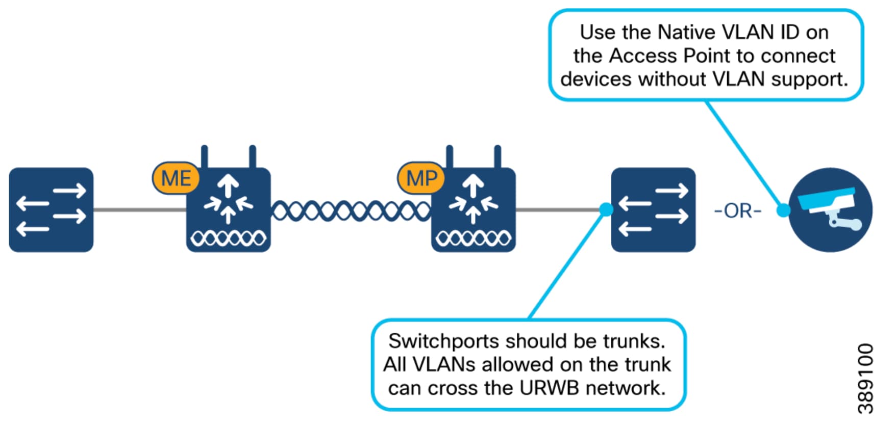
FluidMAX for Fixed Point-to-Multi-Point Topologies
FluidMAX is the URWB operating mode used for fixed point-to-multipoint topologies. It allows the same IW9167E hardware platform to support a fixed multipoint deployment, which is useful when one fixed location, such as a tower or highwall site, must provide backhaul toward multiple fixed endpoints in the mine.
FluidMAX is configured per radio slot. A FluidMAX radio can be configured as primary or secondary. The primary node dictates the operating frequency for the cluster, while secondary nodes can use autoscan to discover a matching primary with the intended cluster ID and tower ID. Cluster ID and tower ID are used to keep FluidMAX relationships intentional.
The cluster ID identifies the group of radios that are allowed to participate in the same FluidMAX cluster. The tower ID identifies the fixed site or tower context for that cluster. In a mining deployment, this matters because the same mine may have several similar tower patterns, temporary trailers, relocated poles, or repeated pit-edge coverage areas. If IDs are reused casually or documented poorly, a secondary radio may discover an unintended primary or a relocated radio may be difficult to distinguish from the site it replaced. Treat cluster ID and tower ID as part of the RF design record, not just as local radio settings.
FluidMAX can be used with only two nodes, but fixed point-to-point operation is simpler to configure and operate when the topology is only a single fixed link. Use FluidMAX when the design requires fixed point-to-multipoint behavior or when the site expects the link to grow into a multipoint cluster. If the requirement is only a dedicated fixed link between two known locations, fixed point-to-point operation is usually the simpler design choice.
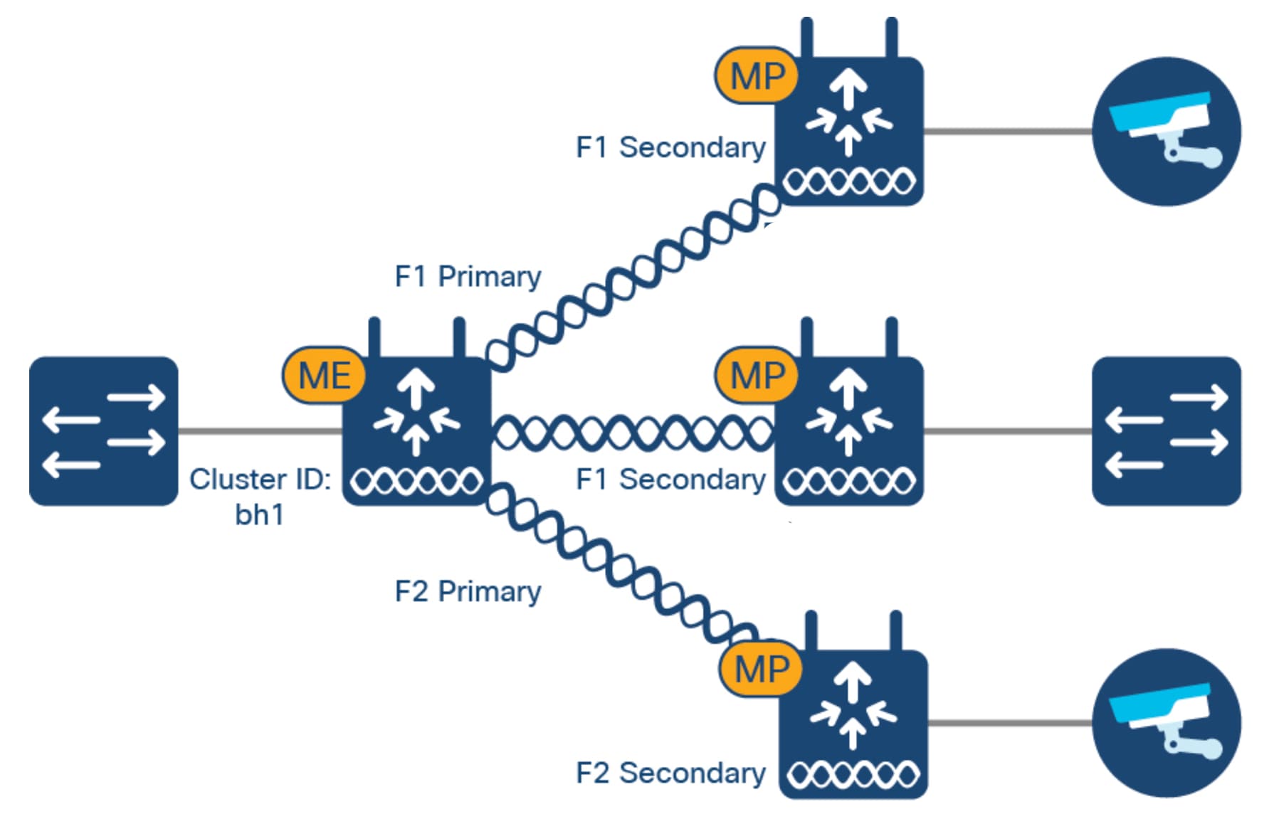 |
The mixed backhaul example below is useful when the site needs to show point-to-point and point-to-multi-point roles in one mining deployment view.
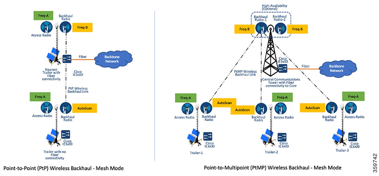
Mobility (Fluidity) for Moving Mining Equipment
Fluidity is the URWB operating mode for mobile mining equipment.
While a vehicle roams, the vehicle radio continually evaluates available infrastructure connections and uses the Fluidity algorithm to select the best available path. If the only available path is weak, the radio stays connected to that path rather than roaming simply to satisfy a static signal threshold.
The objective is usable control, video, and telemetry during real machine motion, not simply staying linked to any radio.
URWB handoff behavior in Fluidity is based on a dynamic decision algorithm rather than on the static threshold logic normally associated with standard Wi-Fi clients. Advanced handoff parameters such as RSSI zone thresholds and hysteresis values can be tuned through IW-Service or the radio CLI, but they should be tuned from measured site behavior rather than copied as defaults into a mining deployment.
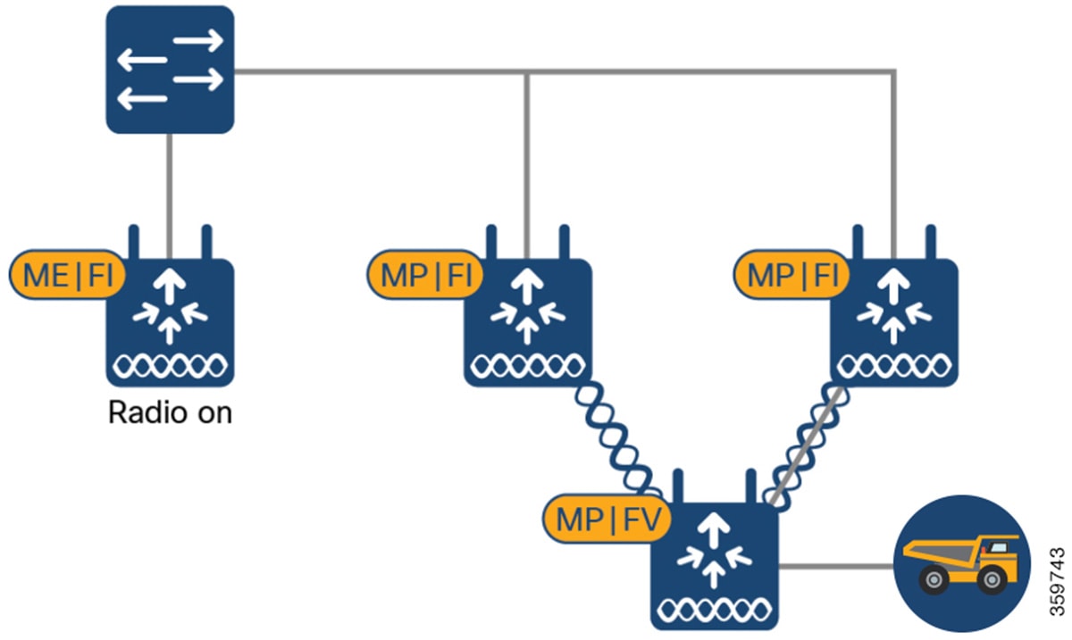
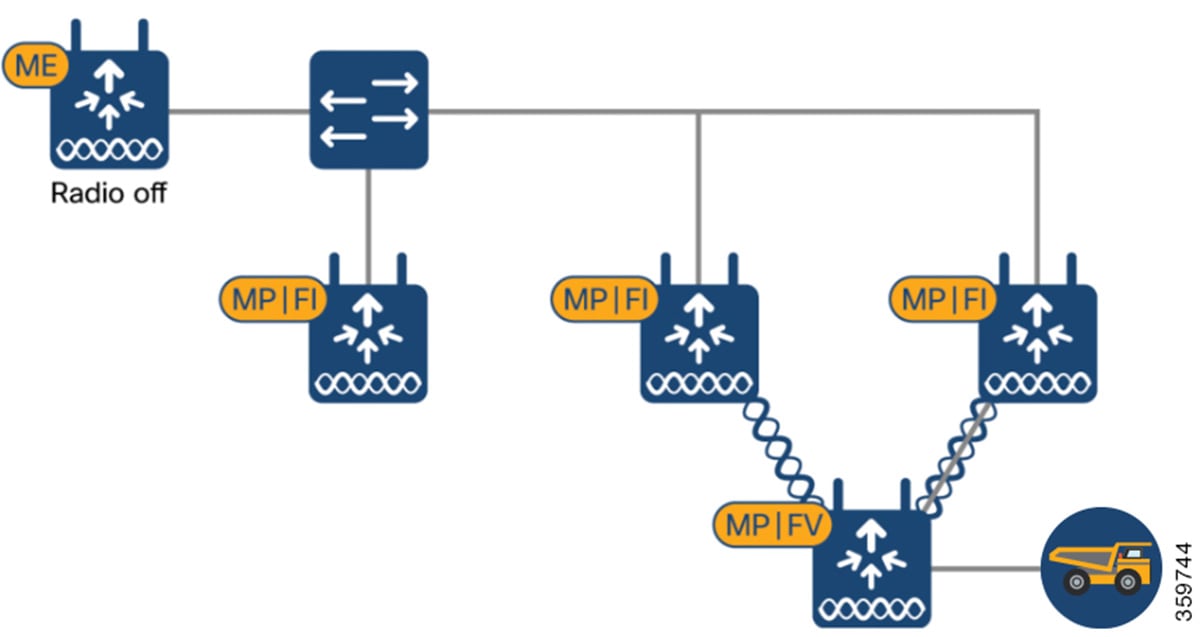
URWB Fluidity Handoff Decision
In standard Wi-Fi behavior, the client typically triggers a roam from configured static thresholds such as RSSI or SNR.
URWB Fluidity uses a dynamic handoff decision algorithm instead. That distinction matters because Fluidity tuning is based on relative candidate quality and hysteresis, not only on a single static signal threshold.
As can be seen in the figure below, the vehicle radio always operates on the top line (RSSI Envelope), handing over from the currently connected radio to the next available radio as soon as the difference in RSSI meets the configured hysteresis threshold.
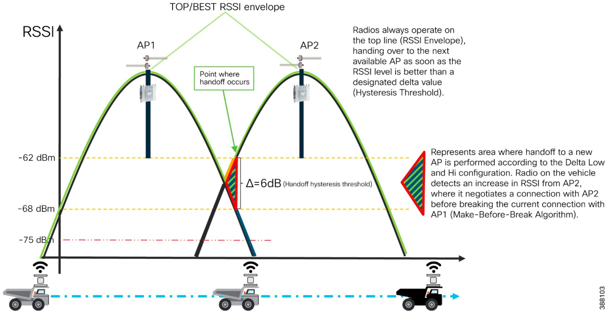
Fluidity Advanced Handoff Tuning for Vehicle Radio Units
● The URWB solution provides certain advanced handoff parameters for vehicle nodes that can be tuned depending on the RF environment to achieve optimal handoffs.
● The RSSI zone threshold and Handoff hysteresis threshold features provide safeguards against unwanted handoffs – in other words, against unreasonably long periods of time between received signal strength from the connected unit falling too low, and a handoff request from a relief unit.
● The relationship between these three settings governs whether a handoff will take place from one unit to another, based on a difference in comparative signal amplitude values over a period.
● The RSSI low/high zone threshold sets the border between the low and high RSSI zones. In this case, as represented by the two graphs below, the -60 dB level marks the border between the low and high RSSI zones.
● The threshold value is always expressed as SNR, with -95 dBm as the reference value, and is always expressed as a value greater than 0. The default value is 35. This equates to -60 dBm.
● The default Fluidity delta-threshold is -60 dBm, and the default delta-high threshold is 6 dB.
● When the serving signal is stronger than -60 dBm, the vehicle radio attempts a handoff only if a candidate infrastructure radio is at least 6 dB better than the current one. If the candidate improvement is below 6 dB, no handoff occurs at that time.
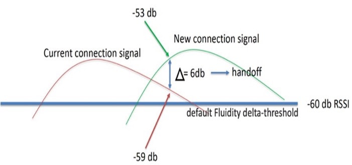
The default delta-low threshold is 3 dB.
When the serving signal is weaker than -60 dBm, the vehicle radio can hand off to a candidate infrastructure radio that is at least 3 dB better than the current one. If the candidate improvement is below 3 dB, no handoff occurs at that time.
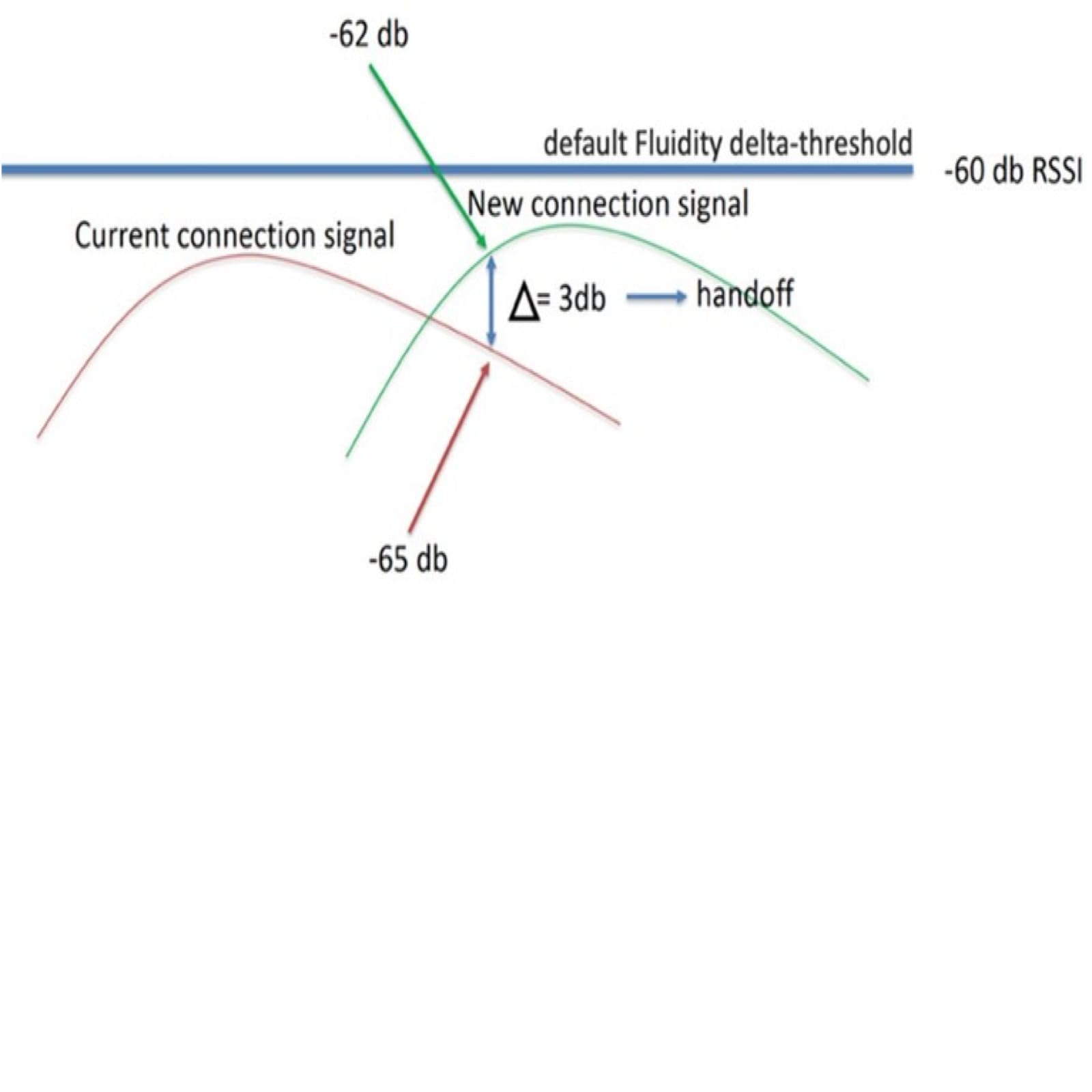
Note: The Fluidity delta-threshold, the delta-high and delta-low values are all configurable to values different from the default using either IW-Service or the radio CLI if needed for your RF environment tuning.
Handoff Hysteresis Interpretation
Handoff hysteresis prevents the mobility radio from reacting to every short-lived difference in received signal. The serving radio should not be abandoned just because another candidate is briefly better during a turn, dust plume, berm shadow, or short terrain break.
● In practice, delta-high and delta-low define how much better the candidate path must be before a handoff is allowed in stronger and weaker RF zones.
● Larger values make the radio more conservative and reduce ping-pong behavior. Smaller values make it move earlier, which helps only when overlap geometry and candidate quality are already engineered correctly.
● Tune hysteresis from route measurements, retry behavior, and real machine motion. Do not treat it as an isolated knob; it interacts with the RSSI-zone threshold, scan behavior, antenna geometry, and the actual operator path.
Define antenna roles separately for vehicle, fixed infrastructure, fixed point-to-point, and fixed point-to-multi-point deployments. Each role has different placement, alignment, beam-shape, and maintenance requirements.
For mining, evaluate antenna selection together with elevation, line of sight, terrain break, obstruction zones, cable path, and service access. A good radio design paired with the wrong antenna type will still produce a poor route.
Vehicle antennas should be chosen for route continuity, machine posture variation, and survivability. In mining, the vehicle is constantly changing angle relative to the infrastructure as it turns, articulates, climbs, descends, or works near berms and pit walls.
That means narrow-beam directional antennas are usually the wrong starting point for vehicle radios. The normal starting point is a vehicle antenna system that preserves usable coverage across movement and posture change rather than one that optimizes only for one ideal heading.
For Tele-Remote Control mobility, choose the vehicle antenna system so it supports the intended chain count, polarization plan, and mounting geometry without creating avoidable cable stress or obstruction from machine structure.
● Use vehicle antennas that tolerate movement and machine posture changes.
● Do not default to very narrow directional vehicle antennas unless the route is highly constrained and has been validated that way.
Sector Antennas for Infrastructure Coverage
Sector antennas are the normal directional coverage tool for infrastructure radios serving a work area or travel corridor. They provide a wider shaped coverage area than directional antennas while still controlling where RF energy is sent.
In mining, sector antennas are useful when the engineer wants to cover a work face, loading area, dump area, or other defined operating zone without wasting energy behind the tower or into unrelated parts of the site.
Sector antennas must be matched to work-area layout. A sector that is too wide creates unnecessary self-interference and reuse problems. A sector that is too narrow creates blind spots at the edges of the movement path or across elevation changes. In practical terms, sector selection is a coverage-shaping decision, not just an antenna-gain decision.
● Use sector antennas when the goal is to cover a defined operating corridor or work zone from fixed infrastructure.
● Choose sector width from the actual route shape, not from a generic preference for the highest gain antenna.
Directional Antennas for Fixed Backhaul and Point-to-Point Roles
Directional antennas are the right choice for fixed backhaul and point-to-point URWB roles where the path is known, narrow, and stable. They concentrate energy into the intended path, improve link budget, and reduce the amount of RF energy sent into unwanted directions.
The tradeoff is alignment sensitivity and maintenance burden. A directional backhaul antenna that drifts mechanically or is installed against the wrong target can fail badly even when the radio configuration is otherwise correct. This is why directional links need stronger as-built documentation, alignment discipline, and post-maintenance validation than broad coverage antennas.
Tele-Remote Control over URWB is built around predictable RF paths between the operator side, the fixed or transportable mine infrastructure, and the radios installed on the mobile machine. The topology choice determines how much operational simplicity, path separation, frequency reuse, and redundancy the design can provide.
The examples in this section describe the standalone URWB architecture options. Section 5.9 provides the deployment and configuration guidance for applying these choices to a production mine.
Standalone URWB Architectures
This scenario uses IW9167E mesh end, IW9167E mesh point, and IW9167E mobility vehicle roles in a standalone URWB topology for Tele-Remote Control. The architecture can start as a small single-frequency design and scale into two-frequency, multi-frequency, or MPO (Multi-Path Operations) designs as the operating area, vehicle count, and resilience requirements increase.
Single-frequency, two-frequency, multi-frequency, and MPO are not all the same kind of decision. Single-frequency, two-frequency, and multi-frequency describe how the RF channel plan is organized. MPO describes whether selected high-priority traffic is duplicated across multiple eligible RF paths. A design can therefore be single-frequency without MPO, multi-frequency without MPO, or multi-frequency with MPO when the site has enough path diversity to justify it.
Table 13. URWB Design Choice Comparison
| URWB Design Choice |
Primary Strength |
Primary Cost or Risk |
Best Fit |
| Single-frequency |
Simplest design to operate, validate, and troubleshoot |
All infrastructure and vehicle traffic shares the available airtime on the same RF channel |
Small or predictable Tele-Remote Control areas with a low number of vehicles |
| Two-frequency |
Improves frequency reuse and supports larger operating areas |
Requires clearer radio-slot, antenna, and frequency planning |
Scale-out from a simple design where one frequency is no longer enough |
| Multi-frequency |
Greatly Improves frequency reuse and supports larger operating areas |
Adds survey, scan-list, validation, and operational support complexity |
Larger or changing work areas with multiple vehicle-facing coverage zones |
| MPO |
Adds duplicate transmission for a protected traffic class when multiple RF paths are available |
Requires QoS discipline, validated path diversity, and additional monitoring |
High-priority Tele-Remote Control traffic where single-path impairment is unacceptable |
Non-MPO is not treated as a separate architecture in this design. It is the normal operating state when MPO is not enabled. The architecture decision is whether the site needs MPO and has the validated RF paths, QoS model, and support process required to use it correctly.
Single-Frequency URWB Topology Example
A single-frequency standalone URWB topology is the simplest Tele-Remote Control RF topology. Every infrastructure radio and vehicle radio uses the same planned RF channel.
This model fits a controlled operating area, a single machine, or a small number of machines where the priority is a topology that is easy to understand and troubleshoot. It is also a practical starting point for validating route behavior, control response, video performance, and antenna placement before expanding the coverage area or vehicle count.
The tradeoff is that all infrastructure and vehicle traffic shares the available airtime on that channel. If the same RF channel carries control, video, telemetry, and management traffic, the design must validate utilization, headroom, and application performance early. A clean association state or acceptable RSSI is not enough; the actual Tele-Remote Control application must be tested while the machine moves through the route.
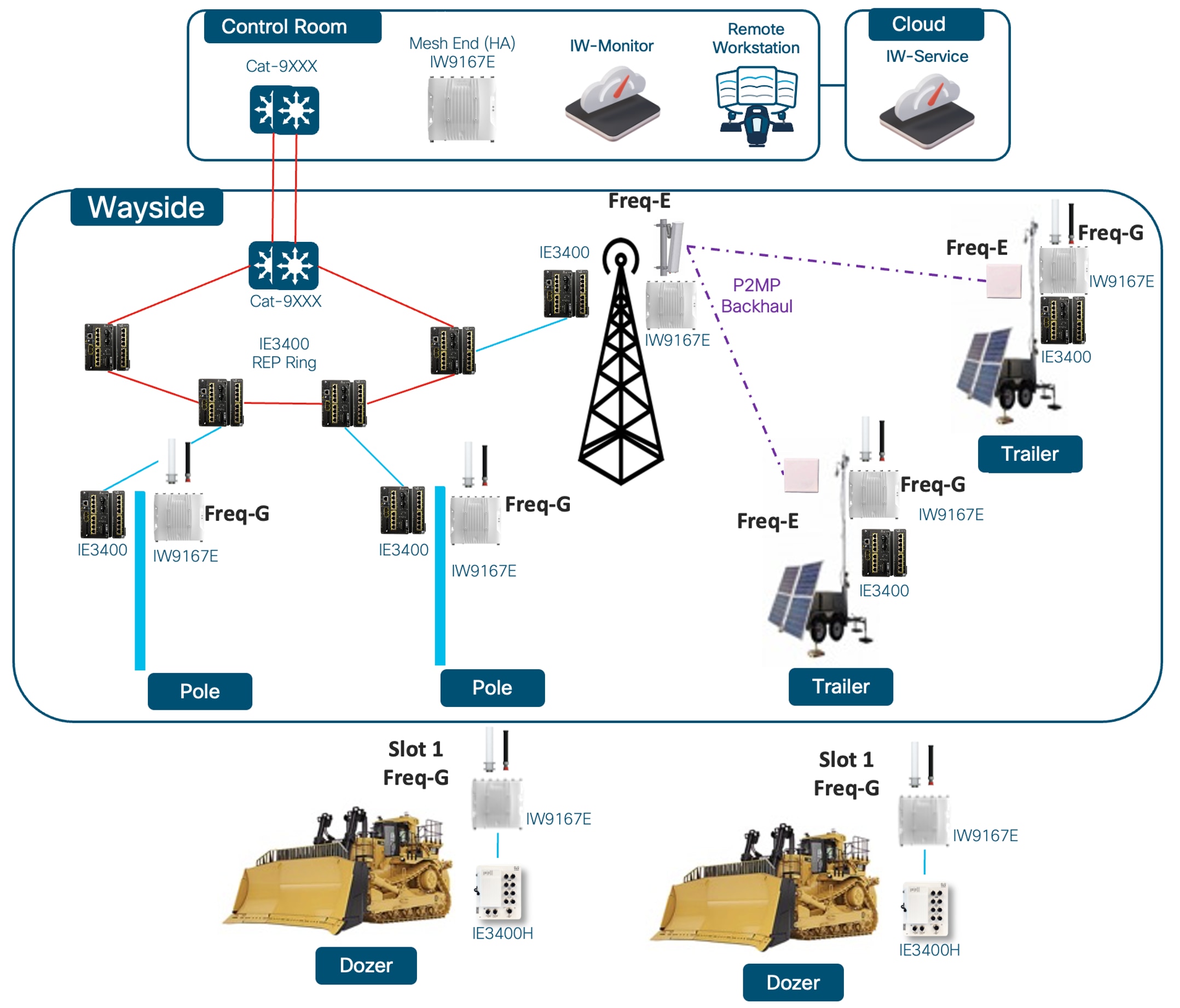 |
Single Frequency URWB Topology
Two-Frequency URWB Topology Example
A two-frequency standalone URWB topology uses two planned vehicle-facing RF channels to reduce channel utilization across the operating area. It does not mean one frequency is reserved for backhaul and the other frequency is reserved for vehicle communication. Instead, each vehicle radio is configured with a statically assigned frequency, and the infrastructure radios are divided between the two planned RF channels so all infrastructure and vehicle traffic is not concentrated on one channel.
This model fits a Tele-Remote Control area where a single-frequency design is operationally simple but creates too much airtime utilization or too little frequency reuse. By dividing infrastructure radios across two planned RF channels, the design reduces how much traffic must share the available airtime on any one channel while keeping the vehicle-side RF behavior deterministic.
The engineering requirement is that the frequency plan must be explicit. Each infrastructure radio group must have a defined frequency, coverage intent, antenna orientation, and expected vehicle path. Each vehicle radio slot must have a statically assigned frequency that matches the infrastructure coverage it is intended to use. The site should not rely on assumptions about which radio will attach to which part of the infrastructure.
The tradeoff is added planning and validation effort. A two-frequency design is still simpler than a larger multi-frequency design, but it requires clear documentation of radio role, fixed frequency, antenna placement, and expected coverage boundary. Validation must prove that the vehicle maintains usable control, video, and telemetry performance as it moves through infrastructure areas served by the two RF channels.
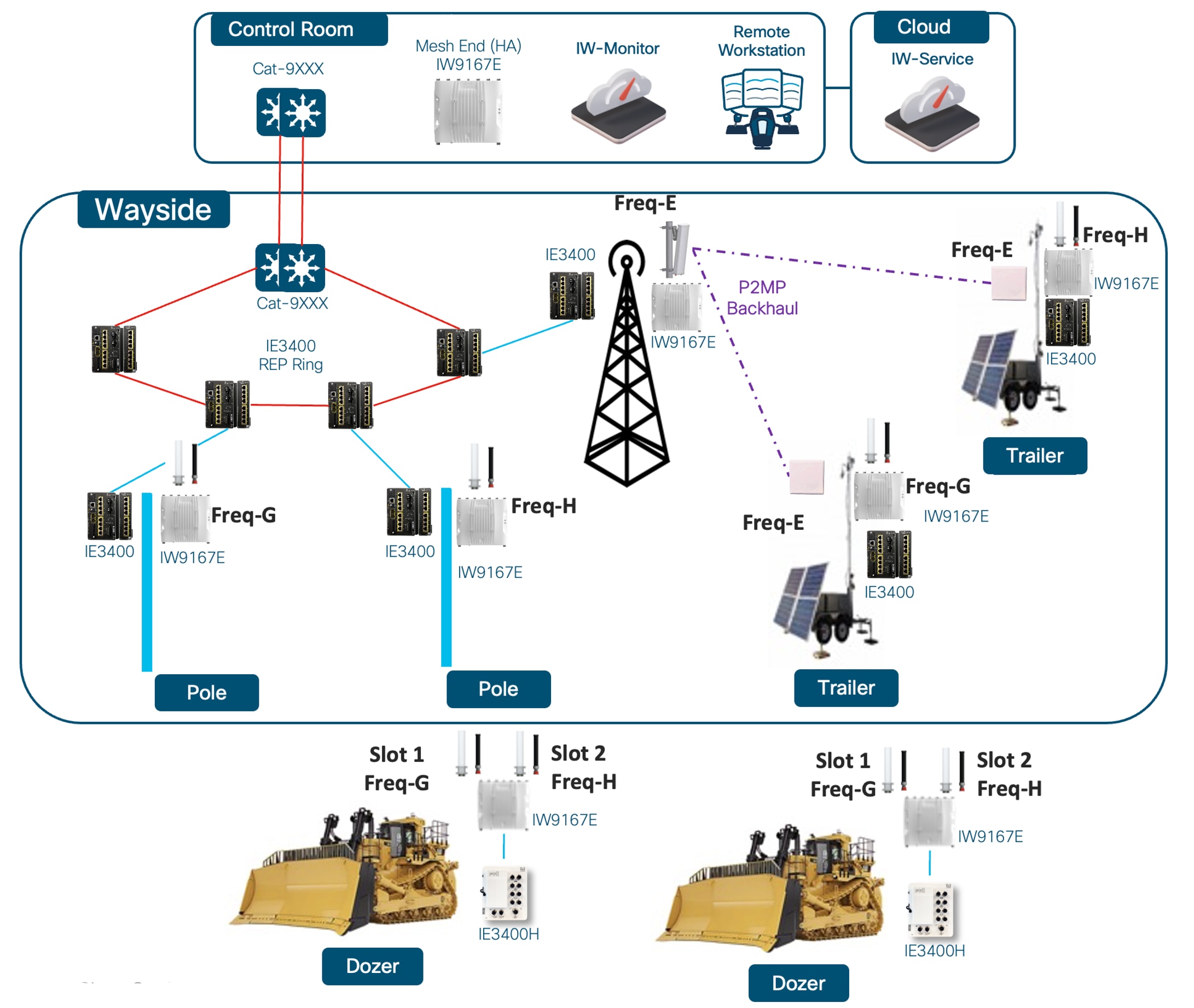 |
Multi-Frequency Standalone URWB Topology Example
A multi-frequency standalone URWB topology extends the same design principle beyond two RF channels. The infrastructure is divided into multiple planned frequency groups so the mine can manage utilization, reuse, and coverage across a larger or more complex Tele-Remote Control operating area.
In this model, vehicle radios use a list of frequencies that match the infrastructure coverage plan. The vehicle radio will have one active radio slot connecting to the infrastructure radio and while the other radio slot is scanning through the frequencies on the list for a better infrastructure radio signal. If a better infrastructure radio signal is found that radio slot will become the active radio slot and the previously active radio slot will become the scanning radio. The design may use multiple vehicle radios, multiple infrastructure groups, and multiple frequency reuse zones depending on the size of the operating area and the number of simultaneously active machines.
The value of the multi-frequency model is controlled reuse. It can support larger operating areas, multiple point-to-multipoint zones, and more active vehicles than a single-frequency design, but only when the frequency plan is engineered around the actual mine geometry. Pit walls, benches, elevation changes, temporary obstructions, and infrastructure relocation can all change which frequency group a vehicle can use reliably.
The tradeoff is operational and initial design complexity. The site must maintain accurate frequency records, infrastructure group boundaries, antenna orientation records, and route validation results. A larger multi-frequency design should be treated as a planned RF architecture, not as a collection of available channels.
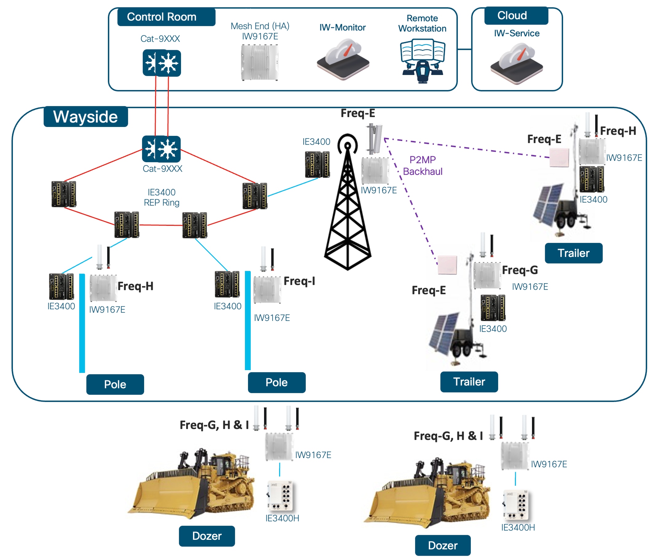
MPO Standalone URWB Topology Example
MPO is used when the topology provides multiple eligible RF paths and the Tele-Remote Control use case benefits from duplicate transmission of one protected traffic class. It is not a replacement for frequency planning. It is an additional resilience mechanism that can be applied when the mine has enough validated path diversity to justify the overhead.
MPO depends on a consistent QoS design because it protects a selected class of service. The design must identify which traffic class needs protection, confirm that the wired OT path and URWB radios treat that class consistently, and verify that multiple RF paths are actually available for that protected traffic. Control traffic and/or video traffic is usually the first candidate for this treatment, but the protected class must match the site’s real application marking model.
The tradeoff is without proper validation of each duplicate RF path it can hide potential RF issues. MPO can improve behavior when one RF path is impaired, but weak, unintended, or unvalidated paths should not be counted as resilience. The site must validate live MPO state, active path statistics, and application behavior under representative motion and obstruction conditions.
Tele-Remote Control Deployment Guidance
Use this section to design, size, secure, and validate the URWB network for Tele-Remote Control.
Before choosing radio settings, start with the application requirement and the mine operating area. Document the per-vehicle throughput requirement, latency and loss targets, video stream count, expected vehicle count in the coverage area, movement pattern, expected signal level at the working distance, and whether the infrastructure radio has wired or wireless backhaul. Use those inputs to size the coverage area and decide how many vehicles one infrastructure radio can realistically support.
Read each subsection as a design decision guide: what the setting changes, what it interacts with, what usually goes wrong, and how to apply it in an above-ground mine.
Apply these settings and design choices to the real operating area, real vehicle count, and real control and video load.
Whenever a design or configuration value is changed, verify that the actual Tele-Remote Control application still works on the real route. A clean association state or a good RSSI number alone is not a pass condition.
Single-Frequency URWB Topology Configuration
After the single-frequency topology is selected, configure the infrastructure-side mobility radio slot and the vehicle-side mobility radio slot to use the same vehicle-facing frequency.
Configure the infrastructure-side AP radio slot for infrastructure mobility service. Set the Fluidity/URWB identity to infrastructure and assign the selected vehicle-facing frequency.
Configure the vehicle-side AP radio slot for vehicle mobility service. Set the Fluidity/URWB identity to vehicle-auto and assign the same vehicle-facing frequency used by the infrastructure-side mobility radio slot.
Validate the final AP radio-slot role, Fluidity/URWB identity, and shared vehicle-facing frequency in the chosen management tool.
Two-Frequency URWB Topology Configuration
After the two-frequency topology is selected, configure the infrastructure radios into the planned vehicle-facing frequency groups. Each infrastructure radio group should have a defined AP radio-slot role, selected vehicle-facing frequency, and expected coverage area.
Configure each infrastructure-side AP radio slot for infrastructure mobility service. Set the Fluidity/URWB identity to infrastructure and assign the planned vehicle-facing frequency for that infrastructure group.
Configure each vehicle-side AP radio slot for vehicle mobility service. Set the Fluidity/URWB identity to vehicle-auto and assign the vehicle-facing frequency that matches the infrastructure coverage area the radio slot is intended to use.
Do not leave the two-frequency design to association behavior or undocumented field assumptions. The implementation should make clear which infrastructure radios use each frequency and which vehicle radio slot is intended to operate with each coverage group.
Validate the per-slot role, Fluidity/URWB identity, assigned vehicle-facing frequency, and infrastructure-to-vehicle frequency mapping in the chosen management tool.
Multi-Frequency URWB Configuration
Use frequency scan on vehicle radios when the site has multiple planned vehicle-facing frequencies and the vehicle needs to evaluate those frequencies while it moves through the operating area.
Frequency scan is a vehicle-side behavior, not an infrastructure-side behavior. A mobile radio has two radio slots; one slot can maintain the active connection while the other evaluates the configured scan list.
Frequency scan is not the same thing as roaming. Scanning discovers better candidate frequencies from the configured list; the roaming/path-selection behavior still chooses the usable connection based on the URWB algorithm and the available RF paths.
Three settings define the scan behavior:
● scan rssi-threshold is the threshold used to decide when the active connection is weak enough to consider scanning.
● scan isolation defines how long that condition must persist before scanning starts.
● scan periodic defines how often the vehicle performs a background scan when threshold-triggered scanning has not occurred.
This as an SNR-style threshold even though the CLI uses the name `rssi-threshold`; verify the software convention before translating an RSSI target into a configured value.
Tune scan threshold, isolation, and periodic timer as one behavior set.
A higher threshold makes the vehicle more willing to scan. A lower isolation time makes it react faster after the threshold is crossed. A shorter periodic timer increases background awareness, but also creates more scan activity.
If the settings are too aggressive, the vehicle chases temporary fades from berms, turns, articulation, dust, or elevation change. If they are too conservative, the vehicle stays on a fading frequency too long and the operator feels the degradation before scan helps.
As the scan list grows, the periodic timer usually needs to grow with it.
Keep the scan list short; only include the frequencies that are necessary in the operating area as scanning the frequency band takes time and the duration will increase for additional frequencies.
In mining, `scan isolation 3000` is a practical starting point because it filters out many short-lived RF dips caused by terrain, machine posture, dust, or brief obstruction while still reacting fast enough for Tele-Remote Control work. Increase it if the vehicle is scanning too often on harmless short dips. Decrease it only if the path can collapse quickly enough that the operator feels the problem before the scan begins.
For a vehicle with two active radio slots and a short scan list such as `36 40 44 40 149 40`, `scan periodic 2000` is a reasonable starting point to validate.
Lengthen the periodic timer as the scan list grows or if the site sees unnecessary scan churn.
Shorten it only when operating-area conditions justify the change and testing shows a real benefit.
Cisco documents the valid ranges as `0-65535` for isolation time, `0-100` for rssi-threshold, and `0-65535` for periodic scan. If both periodic and isolation are set to zero, Fluidity frequency scan is effectively disabled.
Use MPO when the topology provides multiple eligible RF paths and the Tele-Remote Control use case benefits from duplicate transmission of one protected traffic class. MPO is a URWB value-add for high-priority traffic when path diversity exists.
MPO relies on functional end-to-end QoS because it protects one class of service (CoS) at a time. Even if the site does not tune the QoS model well, the default protection behavior can still protect CoS 6 traffic, but the design should explicitly choose the protected traffic class and keep the CoS treatment consistent across the path.
Choose the protected CoS, maximum redundant-path count, and minimum RSSI threshold from the available RF paths and the service that needs protection. Multiple valid RF paths generally improve the protected class; avoid only weak, unintended, or unvalidated paths.
● Configurable options: QoS enabled, 802.1p handling enabled, protected CoS value, maximum redundant path count, minimum RSSI floor for MPO participation, MPO telemetry, and MPO status mode. The design caveat is to verify that the protected CoS is the traffic class the site actually wants to duplicate.
● Validation items: protected CoS, active MPO state, and live MPO path statistics in the chosen management tool.
● Enable MPO after the protected CoS is defined and the site has verified that multiple RF paths are available for the protected traffic class.
● Use MPO wherever the site has multiple valid RF paths and high-priority traffic benefits from duplicate transmission.
Configure multicast only on Mesh End devices. Keep multicast configuration explicit and narrow so the ME only forwards the necessary groups for the application.
To configure the ME for multicast you will need to configure the Multicast Group, Netmask and Destination Address fields.
Note: Note: TheDestination Addressfield accepts the following special values:
● 5.255.255.255 IP address in theDestination Addressfield sends the data to all the mesh point devices over the mesh network. This is applicable only for the downstream data flow.
● 5.0.0.0 IP address in theDestination Addressfield sends the data to the current primary mesh end device. This is useful, especially when the mesh end's fast failover is enabled. This is applicable only for the upstream data flow.
Regulatory Domain, Frequency Selection, and Output Power
Start with the regulatory domain because it defines both the legal channels and the maximum output power available on each one. In mining, that is not just a compliance detail. It changes the real link budget and therefore changes the usable route length, fade margin, and recovery margin.
Frequency choice interacts directly with antenna gain, radio slot selection, channel width, maximum MCS, and the environmental layout. A channel that looks acceptable on paper can still fail at the edge of the route if its legal power limit is lower than the rest of the design assumed.
● Design direction: Choose channels by legal power and route length first.
● Validate: Check route-edge behavior, not just close-in coverage.
DFS can provide cleaner or more available spectrum, which is attractive when the band is crowded or when channel reuse is constrained by the mine layout. The cost is that DFS introduces radar-detection behavior that can force a channel move or service interruption.
That means DFS is not just a spectrum choice. It changes the failure model of the design, the acceptance test, and the amount of uncontrolled change the Tele-Remote Control workflow can tolerate.
● Use DFS when: the spectrum benefit is worth the added operational risk.
● Avoid DFS when: an unexpected channel event is unacceptable for control or video.
Channel width is not just a throughput setting. It determines how much spectrum each infrastructure radio consumes, how much noise the receiver collects, how much SNR remains at distance, and how many clean channels can be reused across the site.
In Tele-Remote Control mining paths, channel width affects maximum usable MCS, long-distance stability, video capacity, control responsiveness, and the number of vehicles one infrastructure radio can support. Each vehicle requires a fixed throughput and latency budget. A narrower channel improves reuse and link margin but reduces the available throughput budget. A wider channel increases peak capacity but is harder to hold unless the RF environment is clean enough across the full route.
Use 40 MHz as the starting point for most Tele-Remote Control vehicle-to-infrastructure URWB paths because it usually provides the best balance of video capacity, link stability, and channel reuse. Move narrower or wider only after validating the route, peer behavior, radio slot, and spectrum plan.
Configure channel width per radio interface and validate the resolved width in the chosen management tool. Typical options for this use case are:
● 20 MHz: Use for difficult RF, longest distance, or maximum reuse.
● 40 MHz: Use as the default balance for most Tele-Remote Control routes.
● 80 MHz: Use only where the environment is clean, distances are shorter, the extra throughput is truly needed, and the added spectrum cost is justified.
Radio Slot Planning and Power Differences
Radio slot planning depends on band, regulatory domain, radio mode, bandwidth, and antenna role. Slot 1 and slot 2 may expose different practical power or bandwidth options depending on the final configuration, so do not assume the two slots are interchangeable.
Slot planning interacts with band, channel, channel width, antenna type, link distance, and infrastructure-versus-mobility role assignment. Validate the slot that carries the critical service at the working distance, not only close to the radio.
Validate the resolved power for the final interface, frequency, and bandwidth in the chosen management tool. This is not unique to mining, but it is critical because small differences in legal power or radio-slot behavior can change the usable Tele-Remote Control coverage area.
● Configurable options: slot role assignment, per-slot frequency, per-slot width, and any slot-specific power setting the platform exposes in the chosen management method.
● Design direction: Put the most demanding infrastructure path on the slot and band combination that provides the validated power, bandwidth, and antenna behavior for that path.
● Verify the final TX power level and TX power in dBm on the slot that carries the critical path.
● Validate: Confirm route-edge behavior for the final slot assignment, not just near-radio performance.
Maximum MCS controls the top of the rate ladder that the radio is allowed to use. That setting directly affects how aggressively the link tries to move into higher data rates when signal conditions improve.
The highest MCS values often look attractive on paper but do not hold consistently on long outdoor routes, reflective surfaces, or vehicle paths with changing posture and elevation. If the cap is set too high, the radio spends more time rate shifting between optimistic rates and usable rates. That usually shows up as retries, unstable video, and inconsistent control feel.
Treat maximum MCS as a stability control, not as a throughput target. It interacts directly with channel width, maximum TX NSS, high-efficiency mode, guard interval, reflections, and route distance. A lower but stable cap is usually better than a higher cap that only works when the vehicle is close to the infrastructure radio.
● Configurable option: maximum MCS cap per radio interface, chosen from what the route can actually sustain.
● Bias lower on MCS when: the route is long, reflective, terrain-affected, or the vehicle posture changes often.
● Bias higher on MCS only when: the real route can hold that rate without repeated rate shifting and retry growth.
● After changing maximum MCS, revalidate retries, video stability, and operator control response across the full route.
High-Efficiency (HE) changes how the radio uses airtime and unlocks HE-specific capabilities on supported links. On IW9167E URWB, HE support is slot-dependent and peer-dependent, so it should be treated as part of the radio-to-radio design rather than as a local radio tweak.
For Tele-Remote Control mining, the useful HE benefits are better airtime efficiency on supported links and access to HE-dependent options such as longer guard intervals. HE does not fix weak SNR, poor antenna placement, or an overly aggressive MCS policy.
HE interacts with guard interval, MCS, channel width, and slot capability. Use it when both radios support it and validation shows the link benefits from the HE operating mode.
● Configurable option: High-Efficiency enabled or disabled per supported radio interface.
● Enable HE when: both ends support it and the design needs better airtime efficiency without moving to an unrealistically wide channel.
● Do not expect HE to rescue a weak route. If the path is SNR-limited or reflection-limited, correct the RF design first.
● Remember the interaction: HE changes which guard interval, MCS, and channel-width combinations are practical, so validate the whole radio-to-radio combination together.
Guard interval sets how much timing separation the receiver allows between symbols. In practical terms, it changes how tolerant the link is to delay spread, reflections, and long outdoor paths.
That matters in mining because long infrastructure-to-vehicle paths, low grazing angles, and ground reflections can create enough delayed energy to make short guard intervals unstable even when signal strength looks acceptable. A short guard interval can improve efficiency, but it can also make the link less tolerant of the exact outdoor effects that are common in a mine.
Use longer guard intervals when the route is long, reflective, or has obvious multipath behavior. That usually costs some efficiency, but it often produces a more stable path for control and video. Use shorter guard intervals only when the RF path is clean enough to benefit from them consistently.
● Configurable options: 400 ns, 800 ns, 1600 ns, or 3200 ns per radio interface, subject to HE support and peer capability.
● Bias longer on guard interval when: distance, reflection, or delay spread is the limiting factor.
● Bias shorter on guard interval only when: the route is clean and the efficiency gain is real on the production path.
● Remember the dependency: 1600 ns and 3200 ns guard intervals require HE mode, while 800 ns remains the default baseline.
Antenna Count and Maximum TX NSS
Antenna count tells the radio how many RF chains and ports are active on that interface. On the IW9167E, the CLI uses `a-antenna`, `ab-antenna`, and `abcd-antenna` to represent one, two, or four active chains.
● Slot 1 abcd = ports 4321.
● Slot 2 abcd = ports 5678.
Set antenna count to the real installed antenna system.
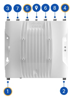
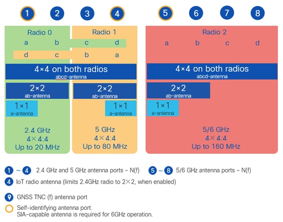
One antenna is usually reserved for very simple or constrained links and gives the least flexibility. Two antennas are common where the infrastructure and vehicle antenna systems are dual-port. Four antennas can be appropriate for fixed point-to-point or other links where both ends, cabling, antenna system, and RF path are designed for four-chain operation.
Use four antennas only when the radio, cabling, antenna system, and link have all been designed for four-chain operation and testing shows a real benefit.
Maximum TX NSS controls how many transmit spatial streams the radio can use. It cannot exceed the enabled antenna count.
If antenna count is higher than maximum TX NSS, the radio keeps the larger physical antenna system but limits transmitted streams to the configured NSS value. That is useful when the design wants antenna diversity but a conservative stream count.
In practice, one spatial stream is the most conservative choice for very long or difficult links. Two spatial streams are a common starting point for mobile Tele-Remote Control links. Four spatial streams can be appropriate for fixed PTP or other clean links where both ends can sustain the RF conditions and the antenna system supports it.
● Configurable options: antenna count per radio interface, typically one, two, or four active chains, and maximum TX NSS set less than or equal to that antenna count.
● Set antenna count to the number of ports and chains that are actually connected and intended to participate on that radio.
● Keep maximum TX NSS less than or equal to the enabled antenna count.
● Use a lower TX NSS than antenna count when you want to keep the physical antenna system but prevent the radio from attempting more streams than the route can sustain.
Polarization for Infrastructure and Vehicles
Polarization is part of the RF design, not just an antenna catalog choice. It changes how strongly the infrastructure and vehicle antennas couple to each other, how the path behaves as the vehicle posture changes, and how much of the energy is affected by reflections from the ground and surrounding structures.
A matched polarization plan preserves link margin. If the infrastructure side and the vehicle side do not match, the result is usually lower received signal, earlier rate shifting, less stable spatial-stream behavior, and more retries. In a mining route, that can look like a power problem or an MCS problem when the real issue is polarization mismatch.
Horizontal and vertical polarization each have tradeoffs.
A single-polarization design is simpler, but less tolerant of environment layout and machine posture changes. A dual-polarized design can improve resilience and make better use of a two-chain system when both ends are designed the same way.
The tradeoff is stricter installation accuracy, port mapping, and chain balance.
For infrastructure radios, dual-polarized antenna systems are often the best starting point because they support two-chain designs and improve tolerance to vehicle posture changes. For fixed PTP links that can support four spatial streams, the antenna and polarization plan should be designed for that higher-chain use case rather than assumed from the mobile baseline.
Using horizontal on one port and vertical on another port of the same radio can be useful, but only when the whole link is designed that way. The benefit is more polarization diversity. The risk is that one chain can become consistently weaker than the other, especially on long paths with strong ground reflections or poor mounting symmetry. That can create uneven chain behavior and make troubleshooting harder.
● Match infrastructure and vehicle polarization plans deliberately. Do not assume different antenna kits will align acceptably by default.
● Use dual-polarized designs as the normal starting point for two-chain mining links unless the route and antenna system clearly justify a different choice.
● Validate polarization on the real route with real machine posture, not just with static close-in testing.
The distance setting tells the radio what path length to expect for link timing behavior. It matters most on longer backhaul-style paths where timing assumptions stop being negligible.
For most Tele-Remote Control vehicle-to-infrastructure paths, leave the distance setting at the software default (3km). If the link is long enough that the default no longer covers it, set the configured distance to about 10 to 15 percent above the actual path length. That gives the radio enough margin without stretching the setting far beyond reality.
Do not inflate the distance value unnecessarily. A distance setting that is much larger than the real path does not create free performance. It only moves the timing model farther away from the real route than it needs to be.
● Configurable option: distance value per radio interface for the links that actually need it.
● The software default is the right choice for most mining Tele-Remote Control paths; record the actual default value shown by the software before changing it.
● Increase distance only when the real backhaul path is long enough to require it.
● When you do increase it, set it roughly 10 to 15 percent above actual path length, not dramatically higher.
Ground Reflections, Delay Spread, and Mitigation
Ground reflections can help MIMO in some conditions, but destructive multipath and delay spread can still hurt real-time traffic. In mining, suspect this only when validation shows symptoms such as jitter, variable MCS, retries, uneven chain behavior, or unstable control/video while RSSI appears acceptable.
Validate the cause before changing the design. Compare chain behavior, retries, MCS stability, guard interval behavior, antenna height, polarization, and path angle. The fix may be antenna placement, polarization, guard interval, MCS cap, or path design, not simply more power.
● Potential fixes: antenna height, antenna placement, polarization, guard interval, and MCS cap.
● Do not assume good RSSI proves the path is clean; verify retry, MCS, chain, and application behavior.
Path Validation for Moving Assets
Validate the operating area under real motion with representative control, video, and telemetry load. Split validation into site-survey considerations and acceptance testing: first confirm coverage, antennas, frequencies, and expected interference; then prove the application works while the machine moves.
A stationary test can pass while the operating area fails during turns, articulation, work-face approach, dump or loading position, elevation change, or temporary obstructions. If those machine states are not tested, the Tele-Remote Control design has not been fully accepted.
● Minimum site-survey considerations: coverage edge, antenna placement, expected interference, obstruction points, and likely operating positions.
● Minimum acceptance-test cases: turning, articulation, work-face approach, dump/loading position, realistic obstruction, and the actual control/video/telemetry load.
QoS Marking, Remapping, and Queue-Based Features
QoS is disabled by default on URWB devices. Turn it on before expecting CoS-based queueing, CoS remapping, shaping, or MPO traffic protection to work the way the design assumes. URWB radios do not mark ordinary traffic themselves; they honor existing markings or use configured remapping for over-the-air treatment.
URWB recognizes markings already present in the packet, either from Layer 3 DSCP or Layer 2 PCP, or uses the configured remapping behavior. Decide whether the site should trust DSCP first or 802.1p first, then configure that intentionally instead of leaving it ambiguous.
If the wired OT side is already classifying and tagging correctly, the radio should preserve that intent. If the traffic is largely unmarked and the engineer plans to use over-the-air queue remapping, QoS must be enabled first or none of that behavior is actually active.
● Configurable options: QoS status enabled, the chosen trust or precedence model for DSCP versus 802.1p, configured remapping where required, and validation of the live CoS map in the chosen management tool.
● Enable QoS first. Then validate the live CoS map before changing remap, shaping, or MPO settings.
● Use 802.1p preference only when the site deliberately wants PCP to take precedence over DSCP.
QoS Priorities for Control and Video
This is the starting point for the whole Tele-Remote Control QoS design. Control and safety-relevant telemetry must stay above video, but video still has to remain usable enough for the operator to work safely.
Once that service priority is set, the rest of the air-interface behavior has to support it. RTS/CTS threshold, aggregation policy, queue remapping, and oversubscription limits should all reinforce the same goal instead of being tuned independently.
The correct treatment depends on stream count, resolution, codec behavior, concurrency, and available airtime. If video is treated too lightly the operator loses situational awareness. If it is treated too aggressively it can harm control during congestion. Reflect the same priority model on the URWB radios and the wired path behind them.
● Design rule: keep control above video, but keep video usable enough for the operator to work safely.
Use the mapping below as a reference when translating packet priority into the access category used over the air. Keep the mapping aligned with the end-to-end queue model and with any CoS-based protection applied elsewhere in the path.
Table 14. Mapping between Packet Priority and Access Category
| Priority |
DSCP |
ToS |
Access Category |
| 0 |
0-7 |
0-31 |
BE |
| 1 |
8-15 |
32-63 |
BK |
| 2 |
16-23 |
64-95 |
BK |
| 3 |
24-31 |
96-127 |
BE |
| 4 |
32-39 |
128-159 |
VI |
| 5 |
40-47 |
160-191 |
VI |
| 6 |
48-55 |
192-223 |
VO |
| 7 |
56-63 |
224-255 |
VO |
RTS/CTS Threshold and Packet Size
RTS/CTS reduces collisions and hidden-node behavior, which is often valuable on long-distance or multi-vehicle Tele-Remote Control paths. The cost is extra overhead and lower peak throughput.
RTS/CTS should be considered as part of the whole QoS and latency design, not as an isolated checkbox. If control and video are both treated as high priority, if aggregation is reduced for those queues, and if the route is carrying many individual frames across the air, collision control becomes more important. RTS/CTS is often what keeps those high-priority frames from stepping on each other.
The threshold matters because RTS/CTS applies only to packets at or above the configured size. If the threshold is too high, the packets you care about may never use RTS/CTS. If it is too low, the design pays protection overhead for too much traffic. That is why the engineer should understand the packet sizes of the real control, telemetry, and video applications before setting the threshold.
Keep the intent aligned on both the infrastructure side and the vehicle side. If one side is built around RTS/CTS protection and the other side is not, the over-the-air behavior will be less predictable than the design assumed.
● Configurable options: RTS/CTS enabled or disabled per radio interface and the threshold size above which frames receive protection.
● Bias toward RTS/CTS when: deterministic behavior matters more than peak throughput.
● Use packet-size knowledge from the actual control and video applications to choose the threshold realistically.
● Match the intent on both sides of the link so infrastructure and vehicle radios are not working to different rules.
A-MPDU, Queue Consistency, and Video Marking
A-MPDU improves efficiency, but it can add aggregation delay on real-time queues. That means it can help capacity while hurting latency if it is applied without considering the control and video profile.
The right choice depends on MCS, channel width, RTS/CTS, and the amount of control-versus-video traffic on the path. Do not disable aggregation everywhere. Disable it only where testing shows that lower latency is worth the airtime cost.
A practical Tele-Remote Control pattern is to carry video in CoS 5 and disable A-MPDU on priority 5 when lower queueing delay matters more than raw airtime efficiency for that class. That keeps the video queue more responsive, but it only makes sense if the service model is consistent with the actual application mix.
Treat infrastructure and vehicle radios as one system.
If one side keeps a queue lean while the other still aggregates heavily, or if each side maps video into a different service treatment, the link will not behave as designed. Queueing, aggregation, and marking intent must match across the air link and continue into the wired OT path.
If upstream applications or switches do not mark video and the traffic presented to the radio is mostly video, an air-side queue remap can still be reasonable. That remap changes radio queue treatment; it does not rewrite the packet marking for the rest of the network.
For example, traffic arriving as CoS 0 can be mapped into the CoS 5 transmit queue across the air. That does not mark the packet end to end; it only changes which air-side queue the radio uses when sending the traffic.
Video marking belongs in this same discussion. Video must stay usable for the operator, but it still cannot outrank control. If the video marking, queue mapping, aggregation behavior, and RTS/CTS policy are chosen independently, the site will usually end up with a design that makes sense on paper but behaves badly on the real route.
Use that queue remap carefully. If CoS 0 contains a broad traffic mix rather than mostly video, remapping all of it into a higher-priority over-the-air queue can destroy the differentiation the design was trying to preserve. The engineer should know what is actually inside the queue before changing how the radio treats it on the air.
This is also why packet-size awareness matters. If the application mix produces lots of small high-priority frames and aggregation is reduced or disabled for those queues, airtime becomes more sensitive to contention. In that situation, the RTS/CTS threshold and the aggregation policy have to be chosen together, not separately.
● Treat A-MPDU as a latency-versus-efficiency decision, not as a universal on/off setting.
● Match aggregation, queue mapping, and marking intent on both infrastructure and vehicle radios.
● If upstream traffic is mostly unmarked video, an air-side queue remap can be useful, but it should not be mistaken for end-to-end remarking.
● Keep control above video, but make sure video remains usable enough for the operator to work safely.
● Check wireless queueing, wired queueing, DSCP mapping, and endpoint behavior as one system.
Oversubscription and Headroom Control
Headroom is what gives the route room to absorb retries, motion, obstruction, and burst behavior. A path that runs near full utilization under normal conditions usually fails first when airtime demand rises.
Higher concurrency improves utilization, but it reduces tolerance for real mining variability. The design target should therefore be usable operator experience at planned concurrency, not laboratory peak throughput.
● Design rule: leave room for the mine to behave like a mine, not like a lab.
AES Encryption and Radio Security Baseline
AES should be the production encryption baseline for the URWB path. In practice, this is not just a security preference. Mixed or inconsistent security settings create avoidable interoperability and troubleshooting problems.
Keep the encryption posture consistent across mesh end, mesh points, and mobility radios so security behavior does not vary along the route.
● Treat AES as baseline production behavior, not as optional hardening.
Segmentation and Management Access
Segmentation defines which traffic types can reach which parts of the network. In a Tele-Remote Control mine, that means control, video, telemetry, management, and administrative access should not all share the same path and trust boundary.
Segmentation must align with OT policy, management access design, and the shared industrial switching domain. If every traffic type shares the same access path, troubleshooting gets slower and the blast radius of mistakes gets larger.
● Document clearly: where management access terminates and which traffic types may cross each boundary.
Mesh-End Backhaul Check - Handoff Inhibition
Use mesh-end backhaul check when the access radio loses reachability to the active mesh end even though local RF service still looks healthy. In wired pole-based designs this helps force vehicles away from infrastructure that no longer has a valid path back to the Tele-Remote Control transport core.
● Enable mesh-end backhaul check only where the access radio has a wired backbone path. Disable it on wireless backhaul paths such as PtP or PtMP links where that failure model does not apply the same way.
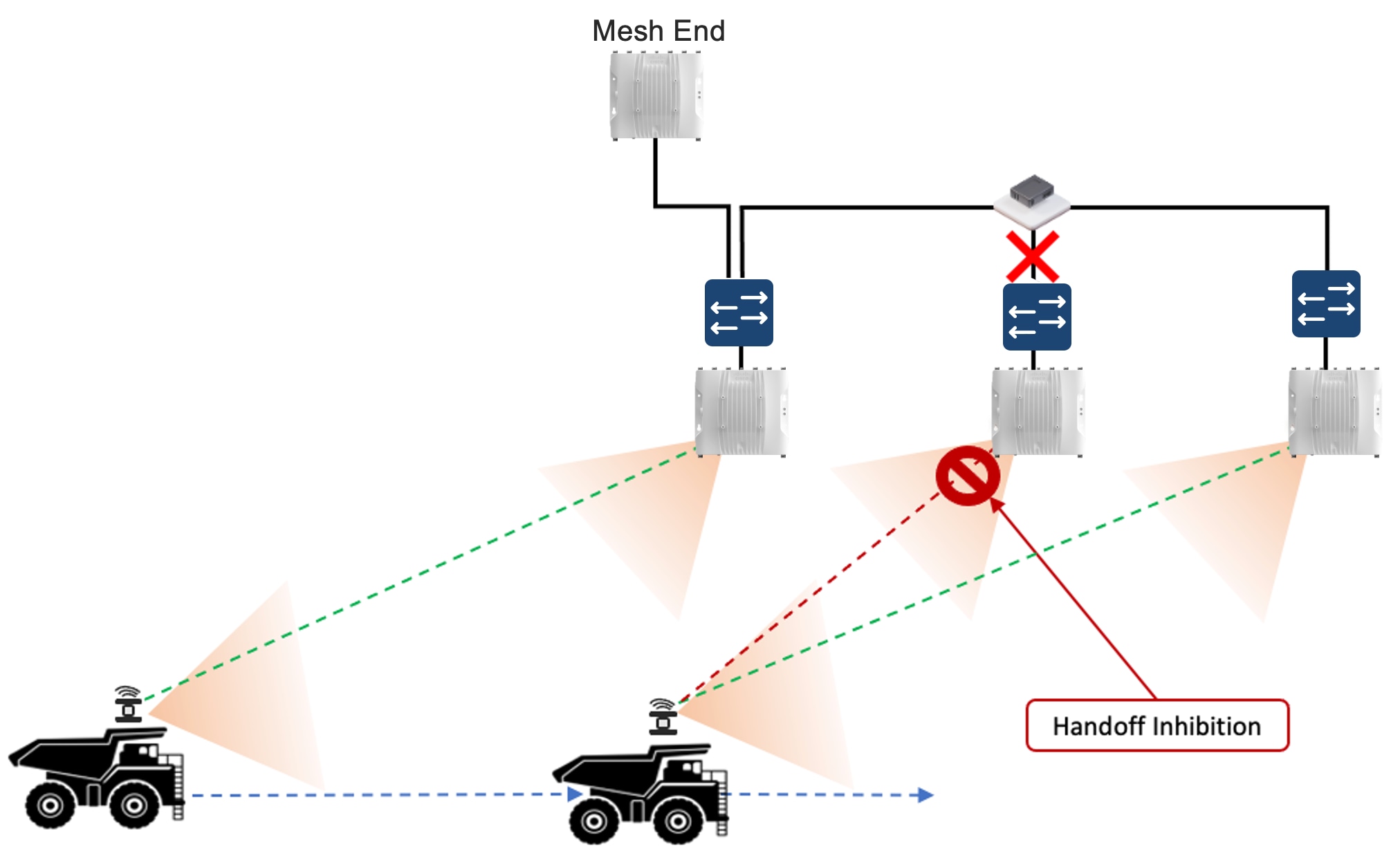
Deployment Best Practices for Any Tele-Remote Control URWB Site
Link Backhaul Check - Handoff Inhibition
Use link backhaul check when an access radio can still provide good RF coverage but has lost the wired Ethernet or fiber path it needs to forward traffic toward the mesh end. The radio should advertise itself as unavailable so connected vehicles move to a valid infrastructure radio instead of staying attached to a dead-end path.
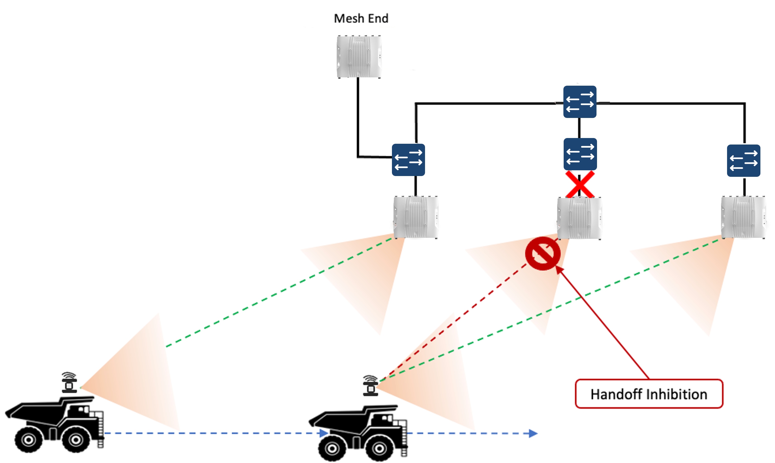
Commissioning and Acceptance Checklist
Commissioning should verify topology state, frequency assignment, antenna orientation, software alignment, and QoS continuity. Acceptance should verify usable control, usable video, and the expected path outcome on the real machine route.
Capture the evidence package explicitly: role map, topology version, frequency plan, antenna validation, path test results, and any accepted concession. That package is what makes later troubleshooting and revalidation efficient instead of starting from scratch.
● If the evidence package is weak, later change control and troubleshooting will also be weak.
Troubleshooting and Symptom Mapping
Troubleshooting should start from the observed production symptom, not from a random configuration knob. In mining, many URWB problems look similar at the application layer, but the first checks are different depending on whether the real fault is path diversity, RF geometry, contention, queueing, or topology drift.
Use the table below as the initial troubleshooting map. It is not a replacement for route testing, but it helps the engineer decide where to look first instead of changing unrelated settings.
Table 15. Troubleshooting and Symptom Mapping
| Observed Symptom |
Likely Causes |
First Checks |
| Vehicle scans too often or changes frequency too aggressively |
Scan list too broad, threshold too aggressive, isolation too short, route has short-lived fades |
Review scan list against the actual engineered route, then check `scan rssi-threshold`, `scan isolation`, and recent route obstructions or posture changes |
| Good RSSI but poor control or unstable video |
Ground reflections, delay spread, unrealistic MCS, wrong guard interval, queue mismatch |
Check retries, actual MCS behavior, guard interval, polarization plan, and whether A-MPDU / RTS-CTS behavior matches the intended QoS design |
| Video unstable while control remains mostly usable |
Video queue mapping wrong, CoS remap inconsistent, A-MPDU behavior wrong for the video class, oversubscription |
Check CoS / DSCP treatment, air-side queue remap, A-MPDU priority behavior, and whether the video class is still below control everywhere |
| Control and video both degrade when more vehicles become active |
Oversubscription, insufficient headroom, collision growth, poor channel-width choice, RTS/CTS threshold not aligned to packet size |
Check airtime demand, concurrency assumptions, channel width, RTS/CTS threshold, packet-size profile, and active vehicle count per infrastructure radio |
| MPO enabled but operator outcome does not improve |
QoS not enabled, wrong protected CoS, insufficient path diversity, duplicate traffic protecting the wrong class |
Check `qos status`, `qos 8021p`, MPO protected CoS, path count, MPO statistics, and whether the topology actually provides multiple useful paths |
| Edge-of-route failures or unstable behavior near terrain changes |
Wrong frequency or slot choice, weak legal power on the chosen channel, antenna geometry issue, polarization mismatch |
Check route-edge SNR, slot assignment, power on the actual interface and channel, antenna alignment, and whether the selected frequency is really the best legal-power option |
| A path worked before but no one can explain why it degraded |
Topology drift, software drift, moved radios, changed frequency plan, terrain evolution |
Check IW-Service / IW-Monitor for node state changes, compare against the approved role map and frequency plan, and review the last known-good acceptance evidence |
Validation covered the in-scope Autonomous Haulage and Tele-Remote Control architectures listed in this document. Testing included the brownfield and greenfield Autonomous Haulage Wi-Fi variants, including IRCM and Non-IRCM behavior, as well as Tele-Remote Control URWB Standalone Greenfield and Tele-Remote Control Wi-Fi Greenfield.
● Testing included route behavior during motion.
● Testing included roaming or path-transition behavior.
● Testing included multicast and video treatment.
● Testing included QoS behavior, policy behavior, and application continuity.
Apply a recommendation as validated only when the site scenario matches the tested design family closely enough in controller model, client type, radio role, RF plan, and traffic pattern. If the site departs materially from the tested scenario, treat the recommendation as a starting point and validate it before production use.
Table 16. Validated Scenario Evidence Model
| Scenario |
Primary Evidence |
Primary Motion Pattern |
Primary Acceptance Focus |
| Autonomous Haulage Brownfield IRCM |
Route-based roam capture, controller mobility evidence, client event history |
Boundary crossing at production speed |
Predictable handoff through the engineered controller overlap zone |
| Autonomous Haulage Brownfield Non-IRCM |
Compatibility validation, route continuity checks, policy comparison |
Movement through mixed legacy and modern sections |
No hidden continuity gap during staged migration |
| Autonomous Haulage Greenfield Non-IRCM |
Roaming validation, FT-PSK behavior, RF corridor measurements |
Steady-state mobility on new infrastructure |
Clean fast-roam behavior and stable corridor design |
| Tele-Remote Control Wi-Fi Greenfield |
Video/control path validation, multicast-direct treatment, QoS evidence |
Operator-controlled movement with active video |
Control protection under realistic video load |
| Tele-Remote Control URWB Standalone Greenfield |
Topology validation, path-loss observation, antenna-role checks |
Movement across engineered URWB paths |
Resilient topology behavior under obstruction and terrain change |
The validation environment represents mine mobility, control flows, video loading, telemetry exchange, and infrastructure topology closely enough to justify the production recommendations in this CVD. The test bed documents hardware models, software versions, baseline policy, RF assumptions, and machine-side integration conditions. Those details matter because a design recommendation is only as strong as the conditions under which it was observed.
Validation was performed using an OEM-integrated machine-control environment representative of production autonomous and Tele-Remote Control mining operations. The document does not claim a universal benchmark where only scenario-specific validation exists. Instead, it shows that the design was tested against representative operational behavior and that the results justify the recommendations inside that tested envelope.
Validation covered coverage, throughput, roaming at speed, packet loss, control latency, video latency, failover behavior, multicast and QoS treatment, and security-policy enforcement. It also covered machine mobility scenarios and interoperability with representative OEM machine-control workflows. These test cases are valuable because they align closely with the real reasons mining networks fail in production: roaming instability, RF mismatch, policy inconsistency, and unexpected application behavior under stress.
● Autonomous Haulage Brownfield IRCM with cross-controller roaming through engineered overlap zones
● Autonomous Haulage Brownfield Non-IRCM variants involving mixed legacy and modern client or infrastructure combinations
● Autonomous Haulage Greenfield Non-IRCM using IW9167E infrastructure and IW9167E WGBs
● Tele-Remote Control URWB Standalone Greenfield using single-frequency and multi-frequency approaches
● Tele-Remote Control Wi-Fi Greenfield using IW9167E infrastructure and IW9167E WGBs on 5 GHz
● Policy-profile verification for passive client, IP MAC binding, client exclusion behavior, WGB VLAN behavior, ARP proxy behavior, and broadcast tagging implications
● Multicast-direct and QoS treatment validation where relevant to video or traffic replication behavior
Reuse this structure for site acceptance, post-change validation, and periodic revalidation as mine conditions evolve.
When gathering your results present measured values as measured values and present design targets as design targets. Do not mix them.
● Include vehicle type, speed, route, and antenna geometry with every published result.
● Include band, channel plan, data-rate policy, and retry or impairment condition with every result.
● Include whether multicast direct, video, or other protected traffic was active during the test.
Do not record a universal latency number, vehicle-per-radio number, or route limit without the conditions that produced it.
Site acceptance should include route validation, failover tests where justified, application-path verification, and comparison of measured behavior against the site's agreed target envelope.
Do not accept the design based only on successful association, a clean topology view, or a single throughput test.
KPI Framework and Evidence Model
Include a KPI table for each accepted design state.
For each metric, show the target value or target range, measurement method, route or operating area, and evidence source. Include control-path latency, video-path latency, packet loss during motion, roam completion outcome, retry behavior, cell-edge signal quality, and infrastructure availability.
If a metric varies by scenario, show the difference instead of forcing all scenarios into one number.
The evidence model is just as important as the KPI itself. A measured value should always be linked to a test condition: vehicle type, speed, route, band, application load, and software baseline. That level of evidence is what makes later revalidation meaningful. Without it, the site cannot tell whether a new result is comparable to the previous one.
Table 17. KPI Framework and Evidence Model
| KPI |
Target Type |
Measurement Method |
Evidence Source |
| Control-path latency |
Scenario-specific target range |
Packet capture or application timing reference on route |
Route test evidence and timestamped captures |
| Video-path latency |
Scenario-specific target range |
Operator-path measurement with application and network timestamps |
Recorded Tele-Remote Control validation run |
| Roam completion outcome |
Successful handoff through engineered corridors |
Client/controller event correlation and on-route observation |
Controller logs plus route validation notes |
| Retry behavior |
Bounded under representative load and weather |
RF telemetry and packet capture review |
Radio statistics and scenario captures |
| Infrastructure availability |
Site-defined resilience target |
Controller, backhaul, and switching event history |
Monitoring system records and change log correlation |
Before field deployment, stage and verify software, licensing, compatibility, policy baseline, and management reachability. Before installation, verify mount points, antenna parts, cable assemblies, grounding, weather sealing, and service access.
● Before production, validate route behavior, application behavior, QoS treatment, and observability.
● Record as-built details, route validation outcome, and acceptance evidence for every production route.
● Do not put a route into production without as-built records and acceptance evidence.
Monitor route performance, RF quality, roaming or path behavior, controller or mesh alarms, and traffic-class health against the validated baseline.
● Investigate drift early. Do not wait for a full application failure.
● Treat recurring retries, rising roam failures, degraded video quality, or controller and mesh instability as production issues even if the link still appears up.
● Keep escalation paths defined across OT, network, operations, and machine-platform support teams.
For Wi-Fi use Catalyst Center dashboards, WLC events, Cisco ISE authentication and policy logs where deployed, Cisco Cyber Vision OT asset and protocol views where deployed, and IW-Service or IW-Monitor for URWB to build a shared incident timeline. A recurring field issue is much easier to isolate when OT and network teams are looking at the same evidence.
Manage the environment under formal software lifecycle and change-control practices. Treat the mine as a changing RF environment, not as a finished deployment.
● Revalidate after changes to pit geometry, road alignment, fleet behavior, application bandwidth, software, antenna layout, or frequency plan.
● Update the site record after every approved change.
● Remove settings and exceptions that no longer serve the current route design.
Keep platform-services lifecycle in step with transport changes. That includes Catalyst Center inventory and lifecycle state, Cisco ISE policy and AAA assumptions where used, Cisco Cyber Vision visibility and asset context where used, and the URWB management record. If those supporting platforms drift away from the accepted design, the network becomes harder to explain and support.
Safe and reliable Autonomous Haulage and Tele-Remote Control depend on an engineered wireless design, not on a generic enterprise WLAN adapted after deployment. Success requires disciplined RF design, resilient transport, strict QoS, correct multicast treatment, controlled roaming behavior, strong security, continuous monitoring, and repeatable validation. Above-ground mining is too dynamic and too operationally consequential for informal wireless design methods.
● Cisco Catalyst 9800 Series Wireless Controllers data sheets: https://www.cisco.com/c/en/us/products/wireless/catalyst-9800-series-wireless-controllers/datasheet-listing.html
● Cisco Catalyst 9800 Series Wireless Controllers release notes: https://www.cisco.com/c/en/us/support/wireless/catalyst-9800-series-wireless-controllers/products-release-notes-list.html
● Cisco Catalyst IW9167E Heavy Duty Series data sheet: https://www.cisco.com/c/en/us/products/collateral/wireless/catalyst-iw9167-series/cat-iw9167e-heavy-duty-ap-ds.html
● Cisco Catalyst IE9300 Rugged Series data sheet: https://www.cisco.com/c/en/us/products/collateral/switches/catalyst-ie9300-rugged-series/catalyst-ie9300-rugged-series-ds.html
● Cisco Catalyst IE3100 Rugged Series data sheet: https://www.cisco.com/c/en/us/products/collateral/networking/industrial-switches/catalyst-ie3100-rugged-series/catalyst-ie3100-rugged-series-ds.html
● Cisco Catalyst IE3100 Heavy Duty Series data sheet: https://www.cisco.com/c/en/us/products/collateral/networking/industrial-switches/catalyst-ie3100-heavy-duty-series/catalyst-ie3100-heavy-duty-series-ds.html
● Cisco Catalyst IE3400 Rugged Series data sheet: https://www.cisco.com/c/en/us/products/collateral/switches/catalyst-ie3400-rugged-series/cat-ie3400-rugged-series-ds.html
● Cisco Catalyst IE3400 Heavy Duty Series data sheet: https://www.cisco.com/c/en/us/products/collateral/switches/catalyst-ie3400-heavy-duty-series/datasheet-c78-742313.html
● Cisco IE3500 Rugged Series data sheet: https://www.cisco.com/c/en/us/products/collateral/networking/industrial-switches/ie3500-rugged-series/ie3500-rugged-series-ds.html
● Cisco IE3500 Heavy Duty Series data sheet: https://www.cisco.com/c/en/us/products/collateral/networking/industrial-switches/ie3500-heavy-duty-series/ie3500-heavy-duty-series-ds.html
● Cisco Catalyst Center documentation and data sheets: https://www.cisco.com/c/en/us/products/cloud-systems-management/dna-center/datasheet-listing.html
● Cisco Identity Services Engine (ISE) documentation: https://www.cisco.com/site/us/en/products/security/identity-services-engine/index.html
● Cisco Cyber Vision documentation: https://www.cisco.com/c/en/us/products/security/cyber-vision/index.html
● Cisco Catalyst Center for Industrial Automation solution brief: https://www.cisco.com/c/dam/en/us/td/docs/solutions/Verticals/Industrial_Automation/IA_Horizontal/IA_Networking/Update-Cisco-Catalyst-Center-for-IA/Cisco_Catalyst_Center_for_IA_SB.pdf
● Cisco Design Zone for Mining: https://www.cisco.com/c/en/us/solutions/design-zone/industries/mining.html
● Wireless Backhaul Deployment for Autonomous Operations in Open-Pit Mining design guide: https://www.cisco.com/c/en/us/td/docs/solutions/Verticals/Industrial_Automation/IA_Verticals/Mining/Mining2_0-CVD/IA-Mining-DG/IA-Mining-DG.html
● Customer-approved site RF survey reports, route maps, and validation artifacts: site-owned internal references with no public URL
Customer-Specific Appendix Content
Use this appendix section to document the site-specific artifacts for the mining network being designed and deployed. These items are not optional background material. Fill them in with the RF data, topology records, software matrix, packet captures, validation results, and acceptance evidence for this site so the document serves as the working engineering record for the network.
● Site-specific RF survey summaries and heat maps
● Spectrum findings by operating area and route segment
● Channel plan and AP naming standard
● Controller, AP, and WGB software version matrix
● Logical and physical topology diagrams
● Packet-capture evidence used for traffic modeling
● Acceptance test scripts and route-based validation records
● Acceptance evidence and sign-off records
● Vehicle integration diagrams and antenna part selections
● Change-control and rollback procedures for wireless modifications
Table 18. Glossary
| Acronym |
Definition |
| A-MPDU |
Aggregated MAC Protocol Data Unit |
| AHS |
Autonomous Haulage System |
| AP |
Access Point |
| ARP |
Address Resolution Protocol |
| CLI |
Command-Line Interface |
| CoS |
Class of Service |
| CVD |
Cisco Validated Design |
| DFS |
Dynamic Frequency Selection |
| DSCP |
Differentiated Services Code Point |
| FT |
Fast Transition |
| FT-PSK |
Fast Transition Pre-Shared Key |
| GNSS |
Global Navigation Satellite System |
| GPS |
Global Positioning System |
| GUI |
Graphical User Interface |
| HE |
High Efficiency |
| ICMP |
Internet Control Message Protocol |
| IGMP |
Internet Group Management Protocol |
| IP |
Internet Protocol |
| IRCM |
Inter-Release Controller Mobility |
| ISE |
Identity Services Engine |
| IT |
Information Technology |
| KPI |
Key Performance Indicator |
| LAN |
Local Area Network |
| LER |
Label Edge Router |
| LSP |
Label Switched Path |
| MAC |
Media Access Control |
| MAP |
Mesh Access Point |
| MCS |
Modulation and Coding Scheme |
| ME |
Mesh End |
| MPLS |
Multiprotocol Label Switching |
| MPO |
Multipath Operation |
| NSS |
Number of Spatial Streams |
| OEM |
Original Equipment Manufacturer |
| OT |
Operational Technology |
| PIM |
Protocol Independent Multicast |
| PSK |
Pre-Shared Key |
| PTMP |
Point-to-Multipoint |
| PTP |
Point-to-Point |
| QoS |
Quality of Service |
| RAP |
Root Access Point |
| RF |
Radio Frequency |
| RSSI |
Received Signal Strength Indicator |
| RTP |
Real-time Transport Protocol |
| RTS/CTS |
Request to Send / Clear to Send |
| SNR |
Signal-to-Noise Ratio |
| SSID |
Service Set Identifier |
| SSO |
Stateful Switchover |
| TCP |
Transmission Control Protocol |
| UDP |
User Datagram Protocol |
| URWB |
Ultra-Reliable Wireless Backhaul |
| VLAN |
Virtual LAN |
| WGB |
Workgroup Bridge |
| WLAN |
Wireless LAN |
| WLC |
Wireless LAN Controller |
| WPA2 |
Wi-Fi Protected Access 2 |
| WPA2-FT-PSK |
Wi-Fi Protected Access 2 Fast Transition Pre-Shared Key |