Cisco Software-Defined Access Solution Design Guide
Available Languages
Bias-Free Language
The documentation set for this product strives to use bias-free language. For the purposes of this documentation set, bias-free is defined as language that does not imply discrimination based on age, disability, gender, racial identity, ethnic identity, sexual orientation, socioeconomic status, and intersectionality. Exceptions may be present in the documentation due to language that is hardcoded in the user interfaces of the product software, language used based on RFP documentation, or language that is used by a referenced third-party product. Learn more about how Cisco is using Inclusive Language.
- US/Canada 800-553-2447
- Worldwide Support Phone Numbers
- All Tools
 Feedback
 Feedback
This document is organized into the following chapters:
| Chapter |
Description |
| Introduction and benefits of SD-Access |
|
| Key components of the SD-Access solution |
|
| Control plane, data plane, policy plane, and management plane technologies |
|
| Fabrics, underlay networks, overlay networks, and shared services |
|
| LAN design principles, Layer 3 routed access, role considerations, and feature considerations |
|
| Site size reference models and topologies |
|
| Migration support and strategies |
|
| Additional references and resources |
Scope
This guide serves as a foundational technical reference for designing Cisco® Software-Defined Access (SD-Access), an intent-based networking architecture that delivers automated, secure, and scalable wired and wireless campus networks. Use this guide to follow best practice recommendations when designing and deploying the solution. In addition to outlining the core architectural components, it highlights key design considerations and migration approaches for existing enterprise LAN environments.
Key focus areas include:
● Solution overview and components: Review of the SD-Access solution building blocks (fabric overlay/underlay, control plane, data plane, policy plane, management plane, and more).
● Design principles and considerations: Core design guidelines across underlay, overlay, segmentation (macro and micro), shared-services integration, wireless, external connectivity, latency, and scale metrics.
● Site reference models: Illustrative models for Fabric in a Box and for small, medium, and large fabric sites.
● Migration and operational readiness: Deployment models and strategies to migrate an existing network to SD-Access.
● Feature scope: Cisco Catalyst™ Center Release 2.3.7.10 and the SD-Access LISP Publisher/Subscriber (Pub/Sub) control plane architecture.
Intended audience
This design guide is intended for stakeholders involved in planning or designing an SD-Access solution—including network architects, implementation engineers, operations teams, and partner organizations—as it outlines the key design concepts needed to build a strong SD-Access foundation. The guide is also aimed at decision-makers who must understand the primary design dimensions and how they affect the overall solution.
Cisco Software-Defined Access is driving the evolution from traditional campus network designs to networks that directly implement the intent of an organization. Running on Cisco Catalyst™ Center hardware, SD-Access is a software application that is used to automate wired and wireless campus networks.
Fabric technology, an integral part of SD-Access, provides wired and wireless campus networks with programmable overlays and easy-to-deploy network virtualization, permitting a physical network to host one or more logical networks to meet the design intent. In addition to network virtualization, fabric technology in the campus network enhances control of communications, providing software-defined segmentation and policy enforcement based on user identity and group membership. Software-defined segmentation is seamlessly integrated using Cisco TrustSec® technology, providing micro-segmentation for groups within a virtual network using Security Group Tags (SGTs). Using Cisco Catalyst Center to automate the creation of virtual networks with integrated security and segmentation reduces operational expenses and reduces risk. Network performance, network insights, and telemetry are provided through assurance and analytics capabilities.
This design guide provides an overview of the requirements driving the evolution of campus network designs, followed by a discussion of the latest technologies and designs that are available for building an SD-Access network to address those requirements.
Benefits of Cisco SD-Access
The following are the key requirements driving the evolution of campus networks to SD-Access:
● Simplified deployment and automation: Network device configuration and management through a centralized controller using open APIs allows for very fast, lower-risk deployment of network devices and services.
● Consistent wired and wireless security capabilities: Security capabilities should be consistent, whether a user is connecting to a wired Ethernet port or connecting over the wireless LAN (WLAN).
● Wireless bandwidth at scale: Placing wireless traffic directly into the switched data plane at the network edge offers wireless endpoints the uplink bandwidth of each access switch. Whether there are 10 or 1000 access switches, this translates to wireless bandwidth that is an order of magnitude higher than the bandwidth available in traditional centrally switched traffic.
● Identity services: Identifying users and devices connecting to the network provides the contextual information required to implement security policies for access control, network segmentation by using scalable group membership, and mapping of devices into virtual networks.
● Network assurance and analytics: The deployment should proactively predict network-related and security-related risks by using telemetry to improve the performance of the network, devices, and applications, even with encrypted traffic.
This chapter is organized into the following sections:
| Chapter |
Section |
| SD-Access solution components |
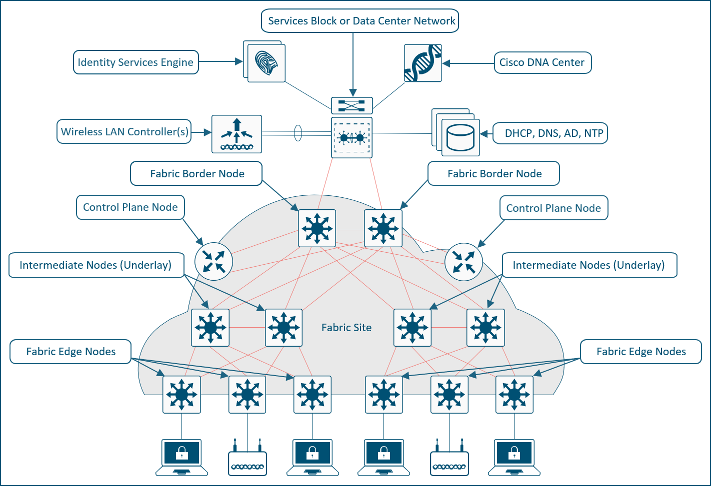
The SD-Access solution is provided through a combination of Cisco Catalyst Center, the Cisco Identity Services Engine (ISE), and wired and wireless device platforms that have fabric functionality. As described later in the Fabric Roles Design Principles section, the wired and wireless device platforms are used to create the elements of a fabric site. This chapter describes the functionality of the remaining two components of SD-Access: Cisco Catalyst Center and the Identity Services Engine.
Cisco Catalyst Center is Cisco's AI-powered network management and automation platform that simplifies operations, secures networks with zero-trust policies, and delivers seamless connectivity for users, applications, and IoT across wired and wireless campus and branch environments. Cisco Catalyst Center can be deployed in physical, virtual, and cloud form factors to match diverse network scales and environments. The physical appliances come in different generations with varying models that differ in hardware specifications, processing power, and form factor. The virtual appliance can be deployed on platforms like VMware ESXi, while cloud options are also available.
| Tech tip |
| For additional information about the Cisco Catalyst Center appliance capabilities, see the data sheet on Cisco.com. |
Cisco Catalyst Center software
Cisco Catalyst Center acts as the centralized manager for a suite of applications and services, powering automation, analytics, visibility, and management across digital-ready infrastructure including Catalyst switches, routers, access points, and Wireless LAN controllers (WLCs). One of its core software packages is SD-Access, which simplifies network design, automates provisioning, and strengthens security across campus environments. With SD-Access, organizations can achieve consistent policy enforcement, highly granular micro-segmentation, and greater operational efficiency, all managed through the intuitive Catalyst Center interface.
Cisco Catalyst Center centrally manages the following configuration and operations workflow areas:
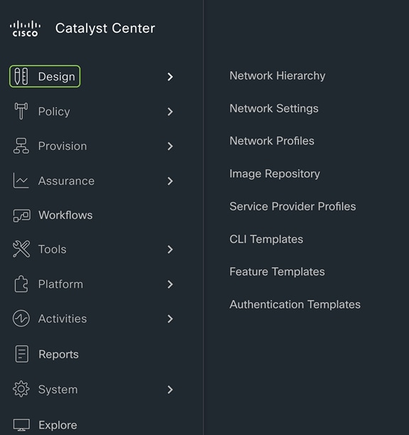
● Design: Creates the structure and framework of your network, including network hierarchy, network settings, DNS, DHCP, IP addressing, site profiles, Software Image Management (SWIM), device/feature templates, and telemetry settings such as Syslog, SNMP, and NetFlow.
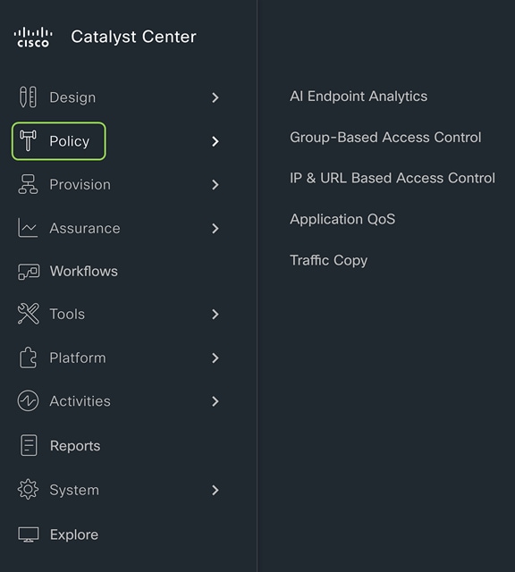
● Policy: Defines business intent by assigning endpoints to Cisco AI Endpoint Analytics, controlling traffic in and out of a device using group-based and IP-based access control policy, and configuring application policies such as quality of service (QoS).
● Provision: Provisions devices and adds them to the managed inventory, supports Cisco Plug and Play and LAN Automation, builds fabric sites with SD-Access components including Zero Trust, establishes virtual networks and transits, and offers a catalog of network services.
● Assurance: Provides proactive monitoring and insights to verify that the user experience matches the intended design, using network, client, and application health dashboards, issue management, sensor-based testing, Cisco AI Network Analytics, and SD-Access.
● Platform: Allows programmatic access to the network and system integration with third-party systems via APIs by using feature set bundles, configurations, a runtime dashboard, and a developer toolkit.
For details of how to implement SD-Access, please refer to SD-Access Deployment Using Cisco Catalyst Center.
Cisco Identity Services Engine (ISE) is a secure network access platform that increases visibility, control, and policy consistency for users and devices connecting to an organization’s network. ISE is a core component of SD-Access, providing network access control by dynamically mapping users and devices to networks and security groups, simplifying end-to-end policy enforcement. Cisco Catalyst Center integrates with ISE over HTTPS for trust establishment, uses REST APIs to automate policy configuration, and leverages Cisco Platform Exchange Grid (pxGrid) for sharing endpoint event and context information.
The SD‑Access solution integrates Cisco TrustSec to provide end‑to‑end, group‑based policy using Security Group Tags (SGTs). SGTs are metadata carried in the header of fabric‑encapsulated packets and are used to enforce identity‑based access controls across the network. Group and policy services are provided by Cisco ISE and orchestrated through Catalyst Center’s policy‑authoring workflows. Cisco ISE is the authoritative system for creating and administering SGTs through tightly integrated REST APIs, while Catalyst Center serves as the single pane of glass to visualize, manage, and consume these SGTs when defining network policies. This architecture simplifies end‑to‑end security policy design, deployment, and enforcement, and scales far beyond traditional approaches that depend on static IP‑based access control lists.
Cisco SD‑Access provides two primary segmentation options, macro‑segmentation with Virtual Networks (VNs) and micro‑segmentation with Security Group Tags (SGTs). Cisco ISE is optional for SD‑Access deployments that require only macro‑segmentation, but it becomes mandatory when identity‑based micro‑segmentation is required. Integrating Catalyst Center with Cisco ISE enables identity‑based policy management that dynamically maps users and devices into security groups while also unlocking a broad set of additional capabilities such as:
● Guest access workflow: Centralized workflow in Catalyst Center automates WLC, fabric nodes, and ISE policy configuration for guest SSIDs.
● Host onboarding: Automates the deployment of Identity Based Networking Services (IBNS) 2.0–based 802.1X/MAC Authentication Bypass (MAB) policies; authentication, authorization, and accounting (AAA); and RADIUS settings across all fabric edge nodes through centralized workflows in Catalyst Center.
● Device administration: Automatically deploys centralized AAA and TACACS configurations across all fabric devices.
● Multiple Catalyst Center clusters to ISE: Integrating multiple Catalyst Center clusters with a single Cisco ISE deployment centralizes group‑based policy, and, optionally, Virtual Network definitions, LISP Extranet policies, and shared SD‑Access transits, while still allowing each Catalyst Center cluster to operate and manage its own fabrics independently.
● Asset visibility/AI Endpoint Analytics: Increases endpoint visibility, improves security posture, and reduces the operational effort required to classify and control devices on the network. Uses deep packet inspection on Catalyst 9000 switches plus AI/ML to discover and profile IT, IoT, and OT endpoints, dramatically shrinking the “unknown device” population.
● Group-Based Policy Analytics: Provides insights for creating group-based policies by visualizing communications between security groups, ISE profiles, and Secure Network Analytics host groups to assess the impact of introducing new access controls and understand exactly which protocols are needed in the policies.
● User/device assurance: Combines rich network telemetry with user and device identity to deliver deeper visibility and faster troubleshooting for client issues.
ISE personas
A Cisco ISE node can provide various services based on the persona that it assumes. Personas are simply the services and specific feature set provided by a given ISE node. The four primary personas are:
● Policy Administration node (PAN): A Cisco ISE node with the Administration persona performs all administrative operations on Cisco ISE. It handles all system-related configurations that are related to functionality, such as AAA.
● Monitor and Troubleshooting node (MnT): A Cisco ISE node with the Monitoring persona functions as the log collector and stores log messages from all the Administration and Policy Service nodes in the network. This persona provides advanced monitoring and troubleshooting tools that are used to effectively manage the network and resources. A node with this persona aggregates and correlates the data it collects to provide meaningful information in the form of reports.
● Policy Service node (PSN): A Cisco ISE node with the Policy Service persona provides network access, posture, guest access, client provisioning, and profiling services. This persona evaluates the policies and makes all the decisions. Typically, there would be more than one PSN in a distributed deployment. All PSNs that reside in the same high-speed LAN or behind a load balancer can be grouped together to form a node group.
● Platform Exchange Grid (pxGrid): A Cisco ISE node with the pxGrid persona shares the context-sensitive information from the Cisco ISE session directory with other network systems such as ISE ecosystem partner systems and Cisco platforms. The pxGrid framework can also be used to exchange policy and configuration data between nodes, such as sharing tags and policy objects. TrustSec information such as tag definition, value, and description can be passed from Cisco ISE to other Cisco management platforms such as Catalyst Center and Cisco Secure Network Analytics (formerly Stealthwatch).
ISE supports standalone and distributed deployment models. Multiple distributed nodes can be deployed together to provide failover resiliency and scale. The range of deployment options allows support for hundreds of thousands of endpoint devices. Minimally, a basic two-node ISE deployment is recommended for SD-Access single-site deployments, with each ISE node running all services (personas) for redundancy.
| Tech tip |
| For additional details on ISE personas and services, please see the latest Cisco Identity Services Engine Administrator Guide. For additional ISE deployment and scale details, please see the ISE Performance and Scalability Guide on the Cisco.com Security Community. |
This chapter is organized into the following sections:
| Chapter |
Section |
| SD-Access operational planes |
There are four key technologies that make up the SD-Access solution, each performing distinct activities in different network planes of operation:
● Management plane: Orchestration, assurance, visibility, and management.
● Overlay control plane: Messaging and communication protocol between infrastructure devices in the fabric.
● Data plane: Encapsulation method used for the data packets.
● Policy plane: Used for security and segmentation.
In Cisco SD-Access the management plane is enabled and powered by Cisco Catalyst Center, the control plane is based on LISP (Locator/ID Separation Protocol), the data plane is based on VXLAN (Virtual Extensible LAN), and the policy plane is based on Cisco TrustSec.
Management plane – Cisco Catalyst Center
Cisco Catalyst Center is a foundational component of SD-Access, enabling automation of device deployments and configurations into the network to provide the speed, scale, and consistency required for operational efficiency. Through its automation capabilities, the control plane, data plane, and policy plane for the fabric devices are easily, seamlessly, and consistently deployed. Through the assurance feature, visibility and context are achieved for both the infrastructure devices and endpoints.
A full understanding of LISP and VXLAN is not required to deploy the fabric in SD-Access, nor is there a requirement to know the details of how to configure each individual network component and feature to create the consistent end-to-end behavior offered by SD-Access. Catalyst Center is an intuitive, centralized management system used to automate configuration and policy across the wired and wireless SD-Access network. It takes the user’s intent and programmatically applies it to network devices.
In many networks, the IP address associated with an endpoint defines both its identity and its location in the network. In these networks, the IP address is used both for network layer identification (who the device is on the network) and as a network layer locator (where the device is at in the network or to which network the devices is connected). While an endpoint’s location in the network will change, who this device is and what it can access should not have to change. LISP allows the separation of identity and location though a mapping relationship of these two namespaces: an endpoint’s identity (EID) in relationship to its routing locator (RLOC).
The LISP control plane messaging protocol is an architecture to communicate and exchange the relationship between these two namespaces. This relationship is called an EID-to-RLOC mapping. The EID and RLOC combination provides all the necessary information for traffic forwarding, even if an endpoint uses an unchanged IP address when appearing in a different network location (associated or mapped behind different RLOCs).
Simultaneously, the decoupling of the endpoint identity (EID) from its location allows addresses in the same IP subnet to be available behind multiple Layer 3 gateways in disparate network locations (such as multiple wiring closets), versus the one-to-one coupling of IP subnet with network gateway in traditional networks. The multiple Layer 3 gateways on all the access layer switches are called anycast gateways. This provides the benefit of any subnet being available anywhere without the challenges of Spanning Tree Protocol.
Instead of a typical traditional routing-based decision, the fabric devices query the control plane node to determine the RLOC associated with the destination address (EID-to-RLOC mapping) and use that RLOC information as the traffic destination. In case of a failure to resolve the destination RLOC, the traffic is sent to the default fabric border node. The response received from the control plane node is stored in the LISP map cache, which is merged with the Cisco Express Forwarding table and installed in hardware.
LISP's architecture introduces several key benefits that enhance network scalability, efficiency, and flexibility:
● Selective, pull-based control plane: This approach reduces unnecessary network updates and flooding, leading to more efficient resource use and supporting seamless network scalability.
● Support for extensible addresses: The LISP Canonical Address Format (LCAF) allows for the encoding of additional metadata beyond traditional address families, supporting advanced use cases and future growth of new features and capabilities.
● Superior mobility for wired and wireless endpoints: LISP enables fast convergence and seamless roaming for wireless clients, while also supporting wired endpoint mobility. This means any wired endpoint can connect at any location within the network and automatically receive the correct access, security policies, and services.
● Wired and wireless consistency: Unified control mechanisms help ensure that policies, configurations, and troubleshooting are consistent across both wired and wireless domains.
● Open, standards-based foundation: LISP is based on open standards and has matured over more than a decade, providing long-term stability and interoperability.
VXLAN is an encapsulation technique for data packets. When encapsulation is added to these data packets, a tunnel network is created. Tunneling encapsulates data packets from one protocol inside a different protocol and transports the original data packets, unchanged, across the network. A lower-layer or same-layer protocol (from the Open Systems Interconnection [OSI] model) can be carried through this tunnel, creating an overlay. In SD-Access, this overlay network is referred to as the fabric.
VXLAN is a MAC-in-IP encapsulation method. It provides a way to carry lower-layer data across the higher Layer 3 infrastructure. Unlike routing protocol tunneling methods, VXLAN preserves the original Ethernet header from the original frame sent from the endpoint. This allows for the creation of an overlay at Layer 2 and at Layer 3, depending on the needs of the original communication.
SD-Access also places additional information in the fabric VXLAN header, including alternative forwarding attributes that can be used to make policy decisions by identifying each overlay network by assigning a VXLAN network identifier (VNI). Layer 2 overlays are identified with a VLAN-to-VNI correlation (Layer 2 VNI), and Layer 3 overlays are identified with a Virtual Routing and Forwarding instance (VRF)-to-VNI correlation (Layer 3 VNI or instance ID in LISP).
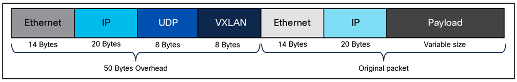
Any encapsulation method is going to create additional MTU (Maximum Transmission Unit) overhead on the original packet. As shown in Figure 1, VXLAN encapsulation uses a User Datagram Protocol (UDP) transport. Along with the VXLAN and UDP headers used to encapsulate the original packet, an outer IP and Ethernet header are necessary to forward the packet across the wire. At a minimum, these extra headers add 50 bytes of overhead to the original packet.
Fabric VXLAN (VNI) encapsulation overhead
Cisco TrustSec decouples access that is based strictly on IP addresses and VLANs by using logical groupings in a method known as Group-Based Access Control (GBAC). The goal of Cisco TrustSec technology is to assign an SGT value to the packet at its ingress to the network. An access policy is then enforced based on this tag information.
An SGT is a form of metadata. It is a 16-bit value assigned by Cisco ISE in an authorization policy when a user, device, or application connects to the network.
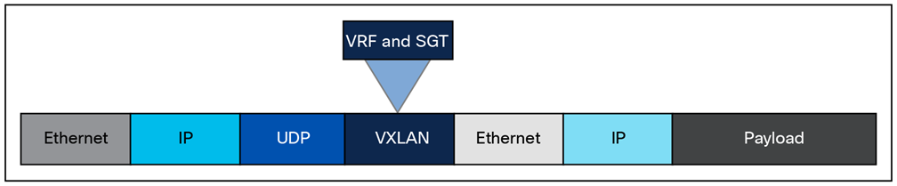
The fabric VXLAN encapsulation method is used both by the data plane and the policy plane. In the policy plane, the alternative forwarding attributes (the SGT value and VRF values) are encoded into the header and carried across the overlay.
Fabric VXLAN alternative forwarding attributes
| Tech tip |
| A bit-level diagram of the VXLAN encapsulation method used in SD-Access fabric, along with low-level details on policy constructs inserted into the header, can be found in Appendix A. |
SD-Access architecture network components
This chapter is organized into the following sections:
| Chapter |
Section |
| SD-Access architecture network components |
The SD-Access architecture is supported by fabric technology implemented for the campus, enabling the use of virtual networks (overlay networks) running on a physical network (underlay network) and creating alternative topologies to connect devices. This chapter describes and defines the word fabric, discusses the SD-Access fabric underlay and overlay networks, and introduces shared services, which are a shared set of resources accessed by devices in the overlay. It provides an introduction to these fabric-based network terminologies that will be used throughout the rest of this guide. Design consideration for these are covered in the next chapter.
Modern organizations rely on their networks not just for connectivity, but also for authentication, security, reliability, and user experience. They host many user types, IoT devices, applications, and security domains across both wired and wireless access. A network fabric addresses these challenges by delivering:
● A simple and repeatable network foundation (underlay) designed for maximum reliability and resiliency
● Multiple logical overlays to deliver different network services for distinct user and device groups
● Role-based segmentation with VRFs and SGTs, instead of relying solely on VLANs and subnets
● Consistent, centrally defined policy for both wired and wireless users and devices
● Seamless mobility, with devices retaining their IP addresses and policies as they move across the network
● Standardized building blocks, making it much easier to scale the network as requirements grow
A fabric is simply an overlay network. Overlays are created through encapsulation, a process that adds additional header(s) to the original packet or frame. An overlay network creates a fully meshed logical topology of tunnels used to virtually connect devices that are built over an arbitrary physical underlay topology. In an idealized, theoretical network, every device would be connected to every other device. In this way, any connectivity or topology imagined could be created. While this theoretical network does not exist, there is still a technical desire to have all these devices connected to each other in a full mesh. In networking, an overlay (or tunnel) provides this logical full-mesh connection.
The underlay network is defined by the physical switches and routers that are used to deploy the SD-Access network. All network elements of the underlay must establish IP connectivity via the use of a routing protocol. Instead of using arbitrary network topologies and protocols, the underlay implementation for SD-Access uses a well-designed Layer 3 foundation inclusive of the campus edge switches; this is known as a Layer 3 routed access design. This foundation ensures performance, scalability, and resiliency, and enables deterministic convergence of the network. End-user subnets and endpoints are not part of the underlay network; they are part of the overlay network.
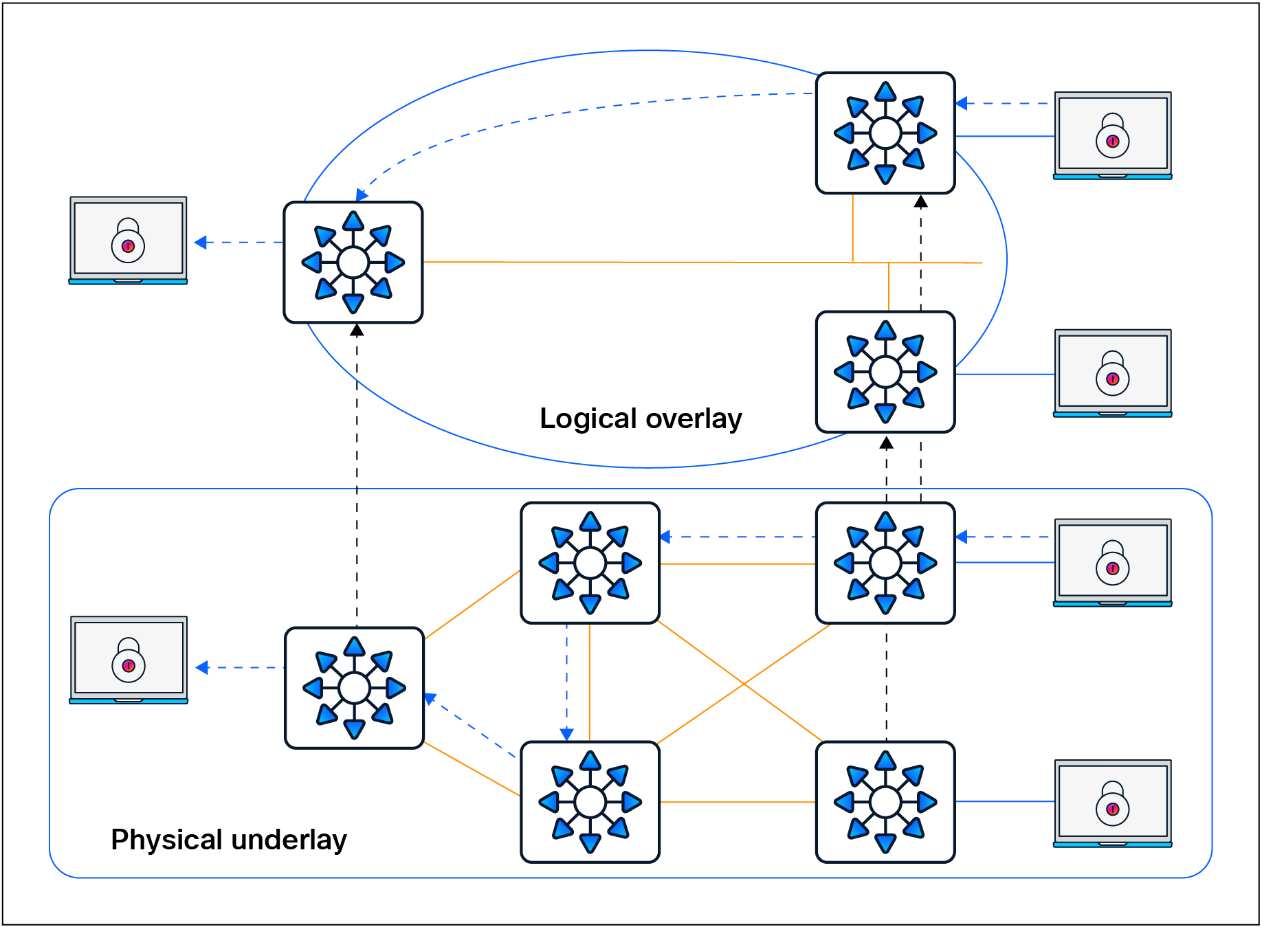
Overlay and underlay relationship
Having a well-designed underlay network helps ensure the stability, performance, and efficient utilization of the SD-Access network. Automation for deploying the underlay is available using the LAN Automation capability of Cisco Catalyst Center, which is discussed in a later section.
Whether using LAN Automation or deploying the network manually, the underlay networks for the fabric have the following general design requirements:
● Layer 3 routed access: The use of a Layer 3 routed access network for the fabric provides the highest level of availability without the need to use loop avoidance protocols such as Spanning Tree Protocol (STP), interface bundling techniques using link aggregation technologies such as EtherChannel, or Layer 2 redundancy technologies like StackWise® Virtual.
● Larger default MTU: VXLAN encapsulation adds 50 bytes of overhead and sets the IP DF (don’t fragment) bit. Enabling a campus-wide and branch-wide MTU of 9100 helps ensure that Ethernet jumbo frames can be transported without being dropped inside the fabric.
● Point-to-point links: Point-to-point routed links provide the quickest convergence times because they eliminate the need to wait for the upper-layer protocol timeouts typical of more complex topologies. Combining point-to-point routed links with the recommended physical topology design provides fast convergence in the event of a link failure.
The fast convergence is a benefit of quick link-failure detection, triggering immediate use of alternate topology entries preexisting in the routing and forwarding table. Implement the point-to-point links using optical technology, as optical (fiber) interfaces are not subject to the same electromagnetic interference as copper links. Copper interfaces can be used, though optical ones are preferred.
● Bidirectional Forwarding Detection (BFD): BFD enhances the fault detection and convergence characteristics of routing protocols. Routing protocols use the absence of hello packets to determine if an adjacent neighbor is down (commonly called a hold timer or dead timer). Thus, the ability to detect liveliness in a neighbor is based on the frequency of hello packets.
● Interior Gateway Protocol (IGP) process for the fabric: While the Intermediate System-to-Intermediate System (IS-IS) Protocol is supported when using LAN Automation, manual deployment of other classless routing protocols such as Open Shortest Path First (OSPF) and Enhanced Interior Gateway Routing Protocol (EIGRP) is also supported.
● Loopback propagation: The loopback addresses assigned to the underlay devices need to propagate outside of the fabric to establish connectivity to infrastructure services such as, DNS, DHCP, and AAA. Loopback 0 interfaces (RLOC) require a /32 subnet mask. These addresses can also be propagated throughout the fabric site. Reachability between loopback addresses (RLOCs) cannot use the default route. They must use a /32 route.
● WLC reachability: Connectivity to the WLC should be treated like reachability to the loopback addresses. The access points (APs) cannot use a default route in the underlay to reach the WLCs. A specific (nondefault) route to the WLC IP address must exist in the global routing table at each switch where the APs are physically connected. This can be a host route (/32) or summarized route.
LAN Automation handles the plug-and-play zero-touch automation of the underlay network for the SD-Access solution. The simplified procedure builds a solid, error-free underlay network foundation using the principles of a Layer 3 routed access design. The LAN Automation feature uses components from the Cisco Plug and Play (PnP) solution, where configuration of the underlay can be orchestrated and devices are automatically added to the Cisco Catalyst Center inventory. LAN Automation is an alternative to manual underlay deployments to onboard multiple switches with SWIM and best-practices configuration using an IS-IS routed access design.
Although there are many alternative routing protocols, the IS-IS routing protocol offers operational advantages such as neighbor establishment without IP protocol dependencies, peering capability using loopback addresses, and agnostic treatment of IPv4, IPv6, and non-IP traffic.
Network design considerations for LAN Automation
There are specific considerations for designing a network to support LAN Automation. These include IP reachability, seed peer configuration, hierarchy, device support, IP address pool planning, and multicast. Additional design considerations exist when integrating the LAN automated network into an existing routing domain or when running multiple LAN Automation sessions. Each of these is discussed in detail below.
IP reachability
Cisco LAN Automation in Catalyst Center deploys a Layer 3 underlay using IS-IS as the primary routing protocol. Border Gateway Protocol (BGP) integration occurs only on seed devices (primary and peer), where you preconfigure it manually for reachability. LAN Automation optionally advertises a LAN Automation IP pool summary route into that BGP process to ensure that Catalyst Center can reach discovered devices without static routes.
Peer configuration
The peer device (secondary seed) can be automated and discovered through the LAN Automation process. However, we recommend configuring the device manually. The two seed devices should be configured with a Layer 3 physical interface link between them. Both devices should be configured with IS-IS, and the link between the two should be configured as a point-to-point interface that is part of the IS-IS routing domain. For consistency with the interface automation of the discovered devices, BFD should be enabled on this crosslink between the seeds, the Connectionless Network Service (CLNS) MTU should be set to 1400, Protocol Independent Multicast (PIM) sparse mode should be enabled, and the system MTU should be set to 9100.
Multicast and LAN Automation
Enable Multicast is an optional capability of LAN Automation. It is represented by a check box in the LAN Automation workflow. When this box is checked, seed devices are configured as rendezvous points (RPs) for PIM – Any Source Multicast (PIM-ASM), and PIM sparse mode will be enabled on the Layer 3 point-to-point interfaces. If redundant seeds are defined, Cisco Catalyst Center will automate the configuration of Multicast Source Discovery Protocol (MSDP) between them using Loopback 60000 as the RP interface and Loopback 0 as the unique interface. Overlay features like Layer 2 flooding and native multicast need underlay multicast configuration. If Layer 2 flooding is required and multicast wasn’t enabled during the LAN Automation process, underlay multicast routing needs to be enabled manually on the devices in the fabric site and MSDP should be configured between the RPs in the underlay.
| Tech tip |
| For additional details on multicast RPs, MSDP, and PIM-ASM, please see the Rendezvous Point Design section. |
Additional IS-IS routing considerations
The seed devices are commonly part of a larger, existing deployment that includes a dynamic routing protocol to achieve IP reachability to Cisco Catalyst Center. When a LAN Automation session is started, IS-IS routing is configured on the seed devices in order to prepare them to provide connectivity for the discovered devices. This IS-IS configuration includes routing authentication, BFD, and default route propagation. These provisioned elements should be considered when multiple LAN Automation sessions are completed in the same site, when LAN Automation is used in multiple fabric sites, and when the fabric is part of a larger IS-IS routing domain.
IS-IS domain password
As part of the LAN Automation workflow in Cisco Catalyst Center, an IS-IS domain password is recommended. The IS-IS domain password enables plain-text authentication of IS-IS Level 2 link-state packets. If the seed devices are joining an existing IS-IS routing domain, the password entered in the GUI workflow should be the same as for the existing routing domain to allow the exchange of routing information.
Bidirectional Forwarding Detection
BFD is provisioned on seed devices at the router configuration level and at the interface level connecting to the discovered devices. BFD is also provisioned on the discovered devices at the router configuration level and at the interface configuration level connecting to the upstream peers.
When configuring the seed device pair before beginning LAN Automation, you’ll need to configure a Layer 3 routed link between them and add the link to the IS-IS routing process. On some platforms, if BFD is enabled at the router configuration level only and not also at the interface level, the IS-IS adjacency will drop. Therefore, BFD should be enabled manually on this crosslink interface to ensure that the adjacency remains up once the LAN Automation session is started. This also means that when integrating the seed devices into an existing IS-IS network, BFD should be enabled on the interfaces connecting to the remainder of the network.
Default route propagation
During LAN Automation, the command default-information originate is provisioned under the IS-IS routing process to advertise the default route to all discovered devices. This command is applied to each seed during the LAN Automation process and excluded for subsequent LAN Automation sessions. If you are integrating with an existing IS-IS network and an IS-IS learned default route is present in the route table, default-information originate won’t be configured on the seed devices.
Onboarding guidelines for LAN Automation with Extended Nodes
SD-Access extended nodes are Layer 2 switches that extend SD-Access VLANs into traditional, noncarpeted areas of the business, often called the extended enterprise. An extended node is either directly connected to a fabric edge node or is part of a chain of extended nodes that ultimately connects to a fabric edge node. For more information about extended nodes, refer to the Extended Nodes section.
Factory-default switches that are to be provisioned as extended nodes should not be physically connected to any switch that is acting as a LAN Automation seed or is currently undergoing a LAN Automation discovery process. This ensures that the LAN Automation session can properly discover and provision only the switches that will participate in IS-IS routing.
| Tech tip |
| Please consult the Cisco Catalyst Center Release Notes and Cisco Catalyst Center SD-Access LAN Automation Deployment Guide for updates, additions, and a complete list of devices supported with LAN Automation. |
An overlay network is created on top of the underlay network through virtualization (virtual networks, or VNs). The data plane traffic and control plane signaling are contained within each virtual network, maintaining isolation among the networks and an independence from the underlay network. Multiple overlay networks can run across the same underlay network through virtualization. In SD-Access, the user-defined overlay networks are provisioned as VRF instances that provide separation of routing tables.
SD-Access allows for the extension of Layer 2 and Layer 3 connectivity across the overlay through the services provided by LISP and VXLAN. Layer 2 overlay services emulate a LAN segment to transport Layer 2 frames by carrying a subnet over the Layer 3 underlay, as shown in Figure 4.
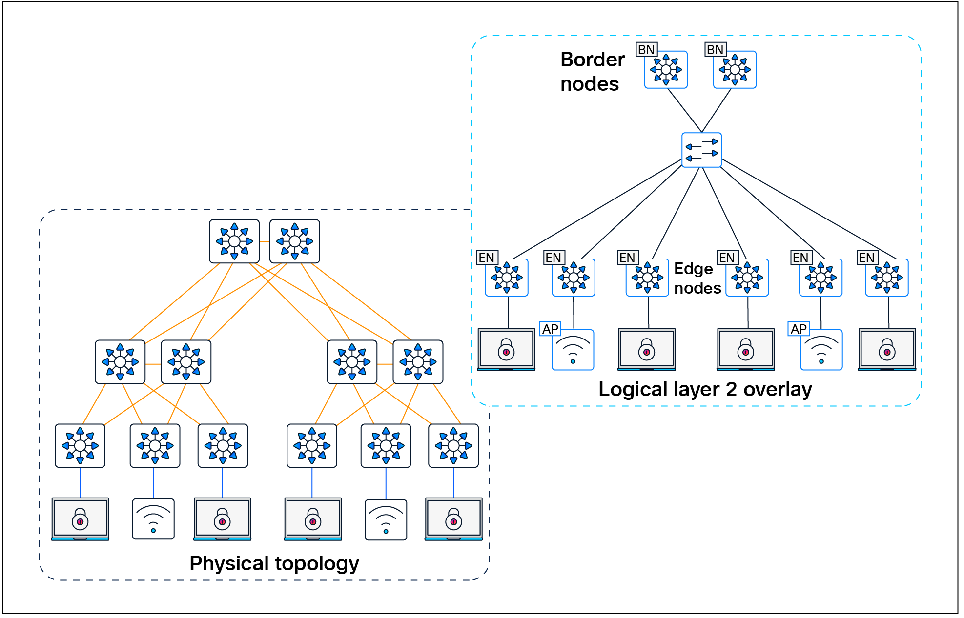
Layer 2 overlay – Logically switched connectivity
Layer 3 overlays abstract the IP-based connectivity from the physical connectivity, as shown in Figure 5. This can allow multiple IP networks to be part of each virtual network. Each Layer 3 overlay, its routing tables, and its associated control planes are completely isolated from one another.

Layer 3 overlay – Logically routed connectivity
The following figure shows an example of two subnets that are part of the overlay network. The subnets stretch across physically separated Layer 3 devices — two edge nodes. The RLOC interfaces, or Loopback 0 interfaces in SD-Access, are the only underlay routable addresses that are required to establish connectivity between endpoints of the same or different subnets within the same virtual network.
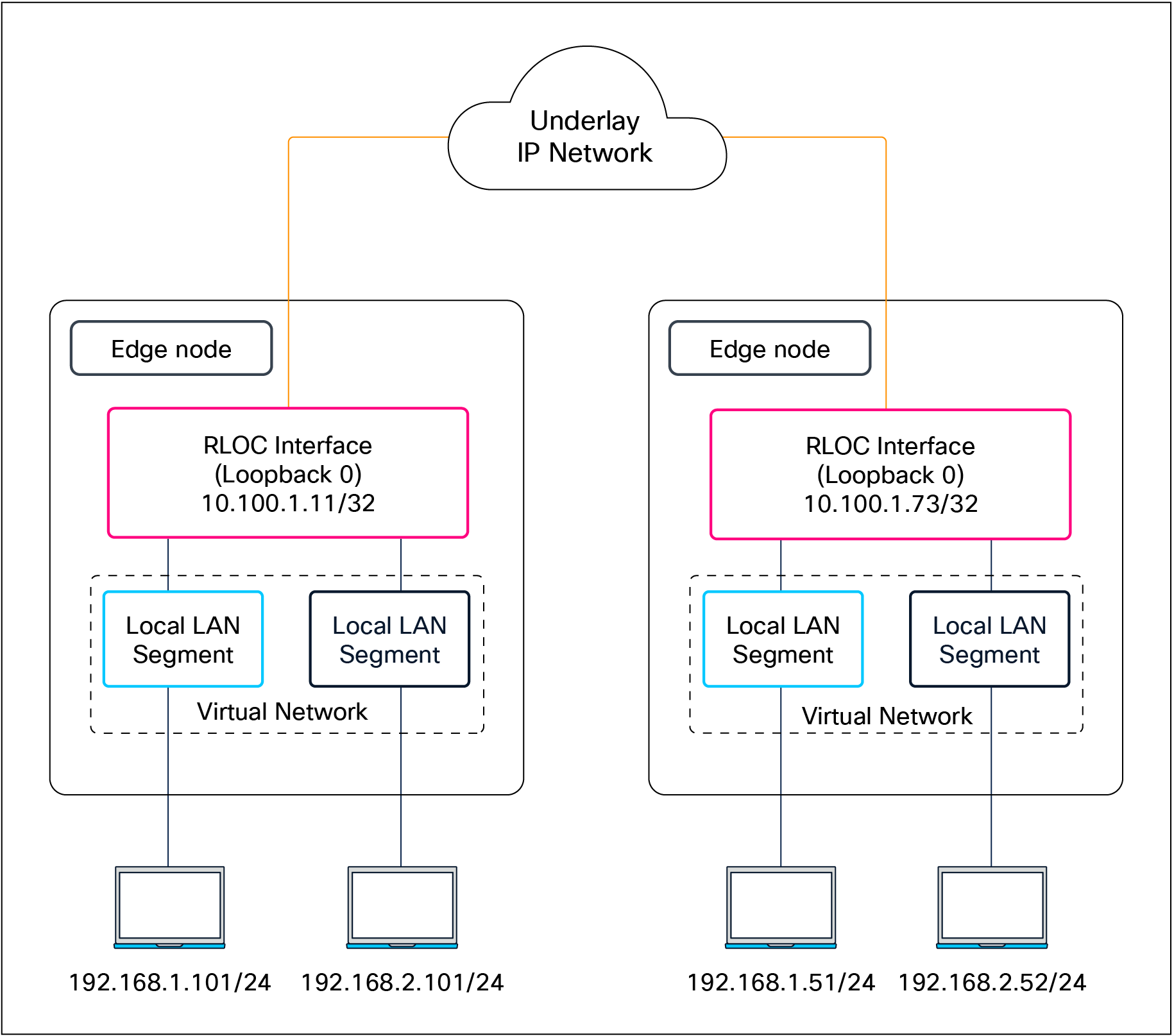
Subnet stretching – Example
In the SD-Access fabric, the overlay networks are used for transporting user traffic across the fabric. The fabric encapsulation also carries security group information used for traffic segmentation inside the overlay virtual networks. Consider the following in the design when deploying virtual networks:
● Virtual networks (macro-segmentation): Use virtual networks when requirements dictate isolation at both the data plane and control plane. In general, if devices need to communicate with each other, they should be placed in the same virtual network. If communication is required between different virtual networks, use an external firewall or other device to enable inter-virtual network communication. Virtual networks provide the same behavior and isolation as VRFs.
● SGTs (micro-segmentation): Segmentation using SGTs allows for simple-to-manage group-based policies and enables granular data plane isolation between groups of endpoints within a virtualized network. Using SGTs also enables scalable deployment of policy without having to do cumbersome updates for these policies based on IP addresses.
● Fewer subnets and simplified DHCP management: In the overlay, IP subnets can be stretched across the fabric without the flooding issues that can happen on large Layer 2 networks. Use fewer subnets and DHCP scopes for simpler IP addressing and DHCP scope management. Subnets are sized according to the services that they support, versus being constrained by the location of a gateway. Enabling the optional broadcast flooding (Layer 2 flooding) feature can limit the subnet size based on the additional bandwidth and endpoint processing requirements for the traffic mix within a specific deployment.
● Overlapping IP subnets: Exactly overlapping anycast gateway addresses are supported for wired endpoints, but only within a single fabric site. Partially overlapping anycast gateways are not supported, for example, 10.0.0.1/24 and 10.0.0.1/23. If overlapping IP subnets need access to shared services, Network Address Translation (NAT) will be required outside of the SD-Access fabric. Overlapping subnets for wired endpoints within Layer 2 VNs (gateway outside the fabric) have no subnet overlap or fabric site restrictions.
| Tech tip |
| The underlay network uses the IPv4 address for the Loopback 0 (RLOC) interfaces on the devices operating in a fabric role. Connectivity in the underlay should use IPv4 routing to propagate the /32 RLOC routes as discussed in the Underlay Network Design section. Endpoints in the overlay space can use IPv4 addresses or dual-stack IPv4/IPv6 addresses. |
Most networks need some form of shared services that can be reused across multiple virtual networks rather than hosting them inside every VN. It is important that those shared services are deployed correctly to preserve the isolation between different VNs accessing those services. The use of a VRF-aware peer directly attached outside of the fabric provides a mechanism for route leaking of shared services prefixes across multiple networks, and the use of firewalls provides an additional layer of security and monitoring of traffic between VNs. Alternatively, SD-Access LISP Extranet can be used to enable access to shared services or internet resources external to the fabric, eliminating the need for traditional BGP-based route leaking between VNs. Examples of shared services include DHCP, DNS, Network Time Protocol (NTP) servers, and internet access, among others. The location of these services is an important consideration in the SD-Access solution. These should be located outside the fabric network, typically upstream of the border node.
● DHCP, DNS, IP Address Management (IPAM), and Active Directory (AD): The same set of infrastructure services can be reused if they support virtual networks. Special capabilities such as advanced DHCP scope selection criteria, multiple domains, and support for overlapping address space are some of the capabilities required to extend the services beyond a single network.
● Internet access: The same set of internet firewalls can be used for multiple virtual networks. If firewall policies need to be unique for each virtual network, the use of a multicontext firewall is recommended.
● IP voice/video collaboration services: When IP phones and other unified communications devices are connected in multiple virtual networks, the call control signaling to the communications manager and the IP traffic between those devices needs to be able to traverse multiple virtual networks in the infrastructure.
● Servers and critical systems: NTP servers, building management systems, network orchestrators, management appliances, support systems, administrative applications, databases, payroll systems, and other critical applications may be required for access by one or many virtual networks.
| Tech tip |
| Place shared‑services points of presence as close as practical to major user populations, and favor regional or local internet and data center exits for latency‑sensitive applications. |
Shared services design
Once the physical design of the services block is determined, its logical design should be considered next. Shared services are commonly deployed in the global routing table, though they are also supported in a VRF. If deployed in a VRF, this routing table should be dedicated only to these shared services.
As discussed in detail later in the External Connectivity section, the endpoint prefix space in the fabric site will be present on the border nodes for advertisement to the external world. However, these prefixes will be in a VRF table, not the global routing table. The External Connectivity section discusses options for connecting the border node to shared services, the internet, and outside the fabric.
With shared services in a dedicated VRF, route leaking (VRF-to-VRF leaking) is administratively straightforward, as it uses BGP route targets under the VRF configuration, although at the expense of creating another VRF to manage. The alternative approach, shared services in the global routing table, requires a different approach to leak routes for access to shared services. The process still requires the same handoff components to the external entity to the border node, though with slightly more touch points. These begin with an IP prefix list for each virtual network in the fabric that references each of the associated subnets. A route map is created to match on each prefix list. Finally, the VRF configuration imports and exports routes that are filtered based on these route maps.
While the second approach, shared services in the global routing table, may have more configuration elements, it also provides the highest degree of granularity. Specific routes can be selectively and systematically leaked from the global routing table to the fabric virtual networks without having to maintain a dedicated VRF for shared services. Both approaches are supported, although the underlying decision on the routing table used by shared services should be based on the entire network, not just the SD-Access fabric sites.
There’s a range of factors that determine the scale of SD-Access fabrics, including the network platforms used, the number of endpoints, and the Cisco Catalyst Center scale, depending on the deployment option and form factor.
Latency in the network is also an important consideration for performance, and the Round-Trip Time (RTT) between Catalyst Center and any network devices it manages must be within tolerances.
For current latency requirements and scale metrics, please see the latest Cisco Catalyst Center data sheet.
SD-Access design considerations
This chapter is organized into the following sections:
| Chapter |
Section |
| SD-Access design considerations |
Management plane considerations |
This chapter provides design guidelines that are built upon principles that allow an SD-Access network architect to build the fabric using next-generation products and technologies. These principles allow for simplified application integration and enable the network solutions to be seamlessly built on a modular, extensible, and highly available foundation design that can provide continuous, secure, and deterministic network operations.
Management plane considerations
The management plane is a critical component of any SD-Access deployment, as it orchestrates the automation, assurance, identity integration, and policy workflows that shape and govern the fabric.
Cisco Catalyst Center is supported as a single node, in three-node clusters, and in a disaster recovery configuration. Each option has different scale and resiliency characteristics. A single node can be deployed as a standalone physical on-premises appliance or as a virtual appliance on cloud or VMware ESXi. If Catalyst Center is deployed as a single-node cluster, wiring, IP addresses, and connectivity should be planned and configured with future three-node clustering in mind.
For high availability, Catalyst Center should be deployed as a three-node cluster. An odd number of nodes is required to maintain quorum in a distributed system, and Catalyst Center supports only a three-node model (not five or seven). Although the cluster is composed of three physical nodes, it operates as a single logical entity accessed through a virtual IP address that is serviced by the resilient nodes within the cluster.
Within a three-node cluster, service distribution provides distributed processing, database replication, security replication, and file synchronization. Software upgrades are automatically replicated across the nodes in a three-node cluster. A three-node cluster will survive the loss of a single node, though it requires at least two nodes to remain operational. Some maintenance operations, such as software upgrades and file restoration from backup, are restricted until the three-node cluster is fully restored. Additionally, not all assurance data may be protected while in the degraded two-node state.
Disaster recovery (DR) adds an additional layer of resilience by protecting against complete cluster failure. Catalyst Center supports two disaster recovery setups: 1+1+1 and 3+3+1. In the event of a primary cluster outage, management operations can be transferred to a designated DR cluster, helping ensure continuity of fabric management and visibility (see the Cisco Catalyst Center Administrator Guide for detailed DR workflows).
While Catalyst Center is not part of the SD-Access data plane or control plane, its availability directly affects how the fabric is provisioned, maintained, and operated. A Catalyst Center outage does not impact SD-Access wired and wireless traffic forwarding, but it does affect:
● All management plane functions: Key areas influenced include fabric provisioning and automation (creation of fabric sites), virtual networks, IP pools, device role assignments (device onboarding), lifecycle management and Plug-and-Play, SWIM, templates, and compliance checks.
● Assurance and telemetry: Fabric, device, and client health monitoring, as well as troubleshooting and path analytics.
● Identity policy and configuration changes: Deployment and synchronization of segmentation policies, SGT assignments, and network-wide configuration updates.
For assurance communication and provisioning efficiency, a Cisco Catalyst Center should be installed in close network proximity to the greatest number of devices being managed to minimize communication delay to the devices. Additional latency information is discussed in the Scale and Latency section.
In the management plane, as of Catalyst Center Release 2.3.7, interfaces can use either IPv4 or IPv6 addressing. However, integration between Catalyst Center and Cisco ISE remains IPv4-only, so IPv4 is still required on the management path for policy, authentication, and pxGrid/External RESTful Services (ERS) interactions.
Within the SD-Access fabric, the underlay is IPv4 only, while the fabric overlay can be configured as either IPv4 only or dual stack for endpoints. Dual-stack anycast gateways on fabric edge nodes allow both IPv4 and IPv6 clients, carrying IPv6 endpoint traffic over the IPv4 fabric underlay. This model lets you introduce IPv6 services and clients in the overlay while keeping the underlay and management/control integrations anchored in IPv4.
| Tech tip |
| For details on Cisco Catalyst Center capabilities, design, and configuration, please see the Maintain and Operate Guides. |
This section is organized into the following subsections:
| Section |
Subsection |
| Policy plane considerations |
Macro- vs. micro -segmentation |
Cisco SD‑Access provides two primary segmentation options, macro‑segmentation with virtual networks and micro‑segmentation with SGTs. Cisco ISE is optional for SD‑Access deployments that use only macro‑segmentation, but it becomes mandatory when identity‑based micro‑segmentation is required.
Zero trust is a security strategy or a framework and also the end state many customers are targeting. Its core principles are to never trust any endpoint or user unless it’s proven trustworthy and then to assign only the minimum necessary access. The figure shows common SD‑Access adoption paths toward a zero‑trust architecture for both existing and new deployment customers. It highlights how you can phase in macro‑segmentation, analytics, and then micro‑segmentation depending on whether you already have Cisco ISE.
SD-Access flexible deployment options
Customers can start their SD‑Access journey with simple macro‑segmentation using virtual networks and later, after integrating Cisco ISE, enhance the design with AI Endpoint Analytics, Group-Based Policy Analytics, and Trust Analytics to gain identity and behavior visibility, ultimately enabling micro‑segmentation with SGTs and group‑based policy as the end state, progressively marching toward a zero‑trust architecture.
Customers with existing LANs that already use Cisco ISE can begin their SD‑Access journey with fabric‑agnostic capabilities such as AI Endpoint Analytics, Group-Based Policy Analytics, and Trust Analytics to understand existing users, devices, and traffic patterns. They can then introduce macro‑segmentation with Layer 2 or Layer 3 virtual networks and ultimately enable micro‑segmentation with SGTs and group‑based policies as the zero‑trust end state.
When Catalyst Center is integrated to ISE, Catalyst Center by default becomes the primary administration point for group‑based access control, and Cisco ISE functions as a read‑only policy engine for TrustSec data. In this mode, Catalyst Center owns a single policy matrix (Production) on ISE and enforces one access contract (SGACL) per TrustSec policy. All fabric sites managed by Catalyst Center operate under a global default‑permit or default‑deny decision, which you choose in the Group-Based Access Control policy settings, and then it’s applied consistently to every site.
Optionally, Catalyst Center can be configured to have TrustSec policy administered directly on Cisco ISE. ISE then becomes the native policy engine for group‑based access control. In this mode, ISE supports multiple policy matrices, allowing different sites to maintain their own TrustSec matrices with independent default-permit or default-deny behavior per site. The same mode also enables enforcement of multiple SGACLs or access contracts per TrustSec policy entry, providing more granular and flexible access control than the single‑matrix, single‑SGACL model driven from Catalyst Center.
SD‑Access supports hierarchical segmentation options built into the solution. Macro-segmentation uses virtual networks or VRFs to isolate large domains such as users (employees, contractors, etc.), guests, and IoT devices (cameras, HVAC, etc.), with each VN providing complete Layer 3 isolation and no inter-VN communication unless there is route leaking. The generally recommended best practice is to keep the number of VNs small and create only those needed for truly necessary domain separation (for example, Campus, Guest, IoT, and possibly a shared services VN), rather than proliferating VNs everywhere, because each additional VN consumes fabric-wide resources and increases complexity—especially on border and peer devices, where every VN requires VRF Lite handoff and associated BGP neighbors.
Within each VN, micro-segmentation provides a second, finer layer of control between specific roles and device types, producing a hierarchical model that aligns with zero‑trust principles. Micro‑segmentation uses SGTs and group‑based policies to control which specific roles or device groups can talk to each other inside a VN. Catalyst Center and ISE support many SGTs, but best practice design guidance is to keep the SGT set as small and meaningful as possible. Each additional SGT increases the size of the policy matrix (NxN relationships) and consumes resources in ISE and the TrustSec enabled network devices. Many deployments end up with on the order of a few tens of well-defined SGTs (for example, per role or device class) rather than hundreds.
In brownfield environments, some customers need to retain their existing third-party Network Admission Control (NAC) solution. In SD-Access, the third-party NAC can be configured to support authentication, authorization, and micro-segmentation in concert with ISE. In this scenario, ISE remains mandatory for SGTs and group-based policy.
In a first supported model, third‑party RADIUS/NAC servers sit behind ISE: 802.1X/MAB authentications are sent to ISE, which proxies to the third‑party server for posture or profiling. ISE then receives an Access‑Accept with a Cisco attribute-value (AV) pair carrying the SGT and applies SD‑Access policy accordingly. This option requires a full-scale ISE deployment.
In the second model, switches send authentication requests directly to the third‑party NAC server for authentication, profiling, and posture assessment, which returns an Access‑Accept containing VLAN name and Cisco SGT assignment. The switch applies the VLAN locally and then queries Cisco ISE only for group‑based policy, so this model does not require a full‑scale ISE deployment because authentication traffic does not terminate on ISE.
The third and final supported design model uses only third-party RADIUS servers without ISE. The third-party RADIUS server is added to Catalyst Center as an authentication server and SD-Access network access devices (NADs) send AAA purely to the third-party RADIUS server. In this design micro-segmentation is not possible because ISE is not present.
Default permit vs. default deny
SD‑Access supports both default‑permit and default‑deny modes through the TrustSec/SGT policy model, each suited to different deployment phases and risk profiles. This behavior is controlled in Cisco ISE and surfaced in the Catalyst Center UI as part of the single‑pane‑of‑glass experience. By default, a “permit any” policy is used, so any source–destination SGT pair without an explicit SGACL is allowed.
Once default deny is enabled, all traffic in the fabric underlay and overlay is blocked by default, including routing protocols, BFD, SSH/Telnet, and multicast and broadcast traffic, so the following prerequisites must be satisfied before moving to this model.
● Starting with Catalyst Center Release 2.3.7.x, TrustSec enforcement is disabled in the underlay for newly LAN-automated links and on AP/extended node VLANs, which is a best practice for default-deny fabrics. For underlays that were LAN automated prior to Release 2.3.7.x, we recommend disabling TrustSec enforcement on all Layer 3 uplinks using Catalyst Center templates.
Multiple Catalyst Center clusters to ISE
Cisco Catalyst Center and ISE integrate to address multiple SD‑Access use cases, as described earlier. SD‑Access customers with large or distributed enterprise fabrics often deploy multiple Catalyst Center clusters for management simplicity, multiregion operations, and compliance needs, while relying on a single ISE cluster to provide globally consistent group‑based access control policy.
The rules and restrictions can be found in the latest Cisco Catalyst Center Administrator Guide.
When Multiple Catalyst Center operation is enabled in Catalyst Center settings, the first cluster that integrates with ISE is designated as the Author cluster and up to four additional Catalyst Center clusters operate as Reader clusters, inheriting and distributing Group-Based Policy (GBP) data (SGTs, access contracts, GBAC policy) and SD-Access data (LISP Extranet policy and shared SD‑Access transit) from the Author to the Reader nodes. TrustSec policy can be managed either on the Author cluster or directly in Cisco ISE.
If multiple Catalyst Center clusters (up to 10 in Release 2.3.7.x) are integrated with the same ISE instance without enabling Multiple Catalyst Center operation, each cluster operates independently, and no GBP or SD‑Access data is shared or synchronized between them. This integration pattern is supported only when TrustSec policy is managed centrally on Cisco ISE.
This section is organized into the following subsections:
| Section |
Subsection |
| Fabric role design principles |
The SD-Access solution is provided through a combination of Cisco Catalyst Center, ISE, and wired and wireless device platforms that support fabric functionality. The wired and wireless device platforms are used to create the elements of a fabric site. A fabric site is a location that has its own border node, control plane node, and edge node. For wireless, a fabric‑mode WLC is dedicated to the site, and Cisco ISE provides centralized policy services.
A fabric role in SD-Access is a software-based function that operates on physical network hardware. These roles are designed for modularity and flexibility—allowing a single device to host one or multiple roles as needed. When provisioning SD-Access fabric roles, it’s important to align their deployment with the underlying network architecture and its functional distribution. Placing different roles on separate devices provides the highest levels of availability, resiliency, and scalability.
This section discusses design principles for SD-Access fabric sites, device roles, and related constructs, including edge nodes, control plane nodes, border nodes, Fabric in a Box, and extended nodes, as well as fabric wireless and transit and peer networks.
The SD-Access fabric edge nodes are the equivalent of an access layer switch in a traditional campus LAN design. The edge node functionality is based on the ingress and egress tunnel routers (xTR) in LISP. The edge nodes must be implemented using a Layer 3 routed access design. An edge node provides the following fabric functions:
● Endpoint registration: Each edge node has a LISP session to all control plane nodes. After an endpoint is detected by the edge node, it is added to a local database called the EID-table. Once the host is added to this local database, the edge node also issues a LISP map-register message to inform the control plane node of the endpoint so the central host tracking database (HTDB) is updated.
● Anycast Layer 3 gateway: A common gateway (IP and MAC addresses) is used at every edge node that shares a common EID subnet, providing optimal forwarding and mobility across different RLOCs. On edge nodes, the anycast Layer 3 gateway is instantiated as a switched virtual interface (SVI) with a hard-coded MAC address that is uniform across all edge nodes within a fabric site.
● Layer 2 bridging: A fabric edge node conducts bridging functionality when traffic originates from and is destined for an endpoint within the same VLAN. The fabric edge nodes exclusively determine whether to route or bridge the packets. They use a Layer 2 VNI (equivalent to a VLAN) within the VXLAN header to bridge the packets to the destination RLOC, where the endpoint is situated. The anycast gateway is an optional component when using the bridging functionality within the fabric. A Layer 2 border is usually deployed when the traffic must bridge out of the fabric.
● Mapping of user to virtual network: An endpoint is placed into a virtual network by assigning the endpoint to a VLAN associated to an SVI that is forwarding for a VRF. Together, these make up the Layer 2 and Layer 3 LISP VNIs, respectively, which maintain fabric segmentation even at the control plane communication level.
● AAA authenticator: The mapping of endpoints into VLANs can be done statically or dynamically using an authentication server. Operating as a Network Access Device (NAD), the edge node plays an integral part in the IEEE 802.1X port-based authentication process by collecting authentication credentials from connected devices, relaying them to the authentication server, and enforcing the authorization result.
● VXLAN encapsulation/de-encapsulation: Packets and frames received from an endpoint, either directly connected to an edge node or through it by way of an extended node or access point, are encapsulated in a fabric VXLAN and forwarded across the overlay. Traffic is sent either to another edge node or to the border node, depending on the destination.
When fabric encapsulated traffic is received for the endpoint, such as from a border node or another edge node, it is de-encapsulated and sent to that endpoint. This encapsulation and de-encapsulation of traffic enables the location of an endpoint to change, as the traffic can be encapsulated toward different edge nodes in the network without the endpoint having to change its address.
In SD-Access, fabric edge nodes represent the access layer in a two- or three-tier hierarchy. The access layer is the edge of the campus. It is the place where end devices attach to the wired portion of the campus network. The edge nodes also represent the place where devices extend the network connectivity out one more layer. These include devices such as IP phones, access points, and extended nodes.
The access layer provides the intelligent demarcation between the network infrastructure and the devices that leverage that infrastructure. As such it provides a trust boundary for QoS, security, and policy. It is the first layer of defense in the network security architecture, and the first point of negotiation between end devices and the network infrastructure. High availability for individual switches is achieved through stacking technologies like StackWise, StackWise Virtual, or chassis-based switches with redundant supervisors and power supplies.
It is recommended that each tier in the network be dual-homed to the next higher tier to ensure robust connectivity; however, if necessary, due to nonhierarchical structured cabling environments, a daisy chain configuration of edge nodes is also supported. The underlay network is routed typically with fast converging protocols such as OSPF or IS-IS, along with features like equal-cost multipath (ECMP), BFD, and NSF with SSO for rapid failover. Design guidelines recommend connecting edge node uplinks to different stack members or supervisors and providing power redundancy beyond minimum requirements to avoid single points of failure, collectively ensuring continuous network availability and fast recovery from failures at the edge node level.
In SD-Access, dual-homing an external Layer 2 switch is supported when it does not create a Layer 2 forwarding path between two edge nodes. The preferred dual-homing design is a port‑channel/Multichassis EtherChannel (MEC) from the external Layer 2 domain into a single logical edge node, implemented as a StackWise switch or StackWise Virtual pair. If StackWise or StackWise Virtual is not possible, another way to achieve dual homing is using active/standby links from the external switching domain, such as Flexlink+, where one link is active and the other is standby, helping ensure that there is never more than one Layer 2 forwarding path into the fabric. Note that correct hardware selection is crucial because not all switch models support Flexlink+.
Dual-homed Layer 2 switches with Flexlink+
The SD-Access fabric also supports dual-homing of wired endpoints to different fabric edge nodes in an active/standby configuration. The endpoint is responsible for keeping one uplink active and forwarding while the other remains in standby and does not forward traffic.
The SD-Access fabric control plane node is built on Locator/ID Separation Protocol (LISP) functionality, combining both the map-server and map-resolver roles within the same node. It maintains a database of all endpoints in the fabric site, mapping each endpoint to its corresponding fabric edge node. This architecture decouples the endpoint’s IP or MAC address from its physical location (the nearest router), enabling optimized mobility, efficient lookups, and seamless policy enforcement across the fabric.
The control plane node enables the following functions:
● Host tracking database (HTDB): The HTDB serves as the central repository of EID-to-RLOC mappings, where the RLOC corresponds to the IP address of the Loopback 0 interface on a fabric node. The HTDB is equivalent to a LISP site in traditional LISP, which includes what EIDs can be and have been registered.
● Endpoint identifier (EID): The EID is an address used for numbering or identifying an endpoint device in the network. The SD-Access solution supports MAC addresses, IPv4 addresses, and IPv6 addresses as EIDs.
● Map server: The LISP map server receives endpoint registrations indicating the associated RLOC and uses these to populate the HTDB.
● Map resolver: The LISP map resolver responds to queries from fabric devices requesting RLOC mapping information from the HTDB in the form of an EID-to-RLOC binding. This tells the requesting device the fabric node to which an endpoint is connected and thus where to direct traffic.
The fabric control plane node contains the database used to identify an endpoint’s location in the network. This is a central and critical function, and is required for the fabric to operate. If the fabric control plane is down, endpoints inside the fabric fail to establish communication to remote endpoints that are not cached in the local database.
For redundancy, we recommend deploying two control plane nodes to ensure high availability of the fabric site, as each node contains a copy of control plane information acting in an active/active state. The devices supporting the control plane should be chosen to support the HTDB (EID-to-RLOC bindings), CPU, and memory needs for an organization based on the number of endpoints. Border nodes and edge nodes register with and use all control plane nodes, so redundant nodes chosen should be of the same type for consistent performance.
The Cisco WLC can communicate with a pair of control plane nodes within a fabric site. The WLC updates the wireless client context information with this pair of control plane nodes. If a fabric site deploys more than a pair of control plane nodes, the client context information may not be updated with all control plane nodes. Therefore, we recommend that you restrict the number of control plane nodes to a pair within a fabric site when using fabric-enabled wireless.
Two LISP control plane implementations are available for use in SD-Access. The original was LISP/BGP, released in 2017, and the more recent one is LISP Pub/Sub (Publish/Subscribe). Pub/Sub offers a range of new capabilities, including:
● Faster convergence: Topology updates are proactively pushed directly to subscribers, enabling faster propagation compared to BGP-based models.
● Reduced protocol complexity: There is no need for BGP in prefix propagation, making the control plane simpler and easier to troubleshoot.
● Configuration simplicity: No mutual redistribution is required between LISP and BGP.
● Scalability and extensibility: Pub/Sub is designed for large and dynamic fabric deployments; adding support for new LISP features is relatively easier.
● Efficient operation: Unnecessary map lookups are reduced and overlay traffic flows are optimized.
LISP Pub/Sub is recommended for all new SD-Access implementations. As of this writing, an automated workflow to migrate existing LISP/BGP sites to LISP Pub/Sub is under development.
In the initial release of the Pub/Sub architecture, subscribers (border nodes) express interest in receiving updates for all registrations for a given instance ID (IID) table, and the publisher (control plane node) proactively pushes reachability information to subscribers. By pushing mappings instead of redistributing them through BGP in LISP/BGP, LISP Pub/Sub removes the dependency on BGP for information exchange within and across fabric sites (when using the optional SD-Access transit control plane). This results in a more efficient, extensible, and scalable control plane architecture.
Cisco IOS® XE Release 17.18.1 introduced support for EID Pub/Sub. It allows edge nodes and Layer 2 border nodes to subscribe to active remote EIDs in the overlay (remote EIDs to which traffic is being sent). Updates for the subscribed EIDs are published immediately to the edge node or Layer 2 border node, further optimizing network convergence speed and efficiency in the LISP Pub/Sub architecture.
Fabric site control plane nodes may be deployed as either dedicated (distributed) or nondedicated (colocated) devices in relation to the fabric border nodes. In a Fabric in a Box deployment, all fabric roles must be colocated on the same device. In most deployments, it is common to deploy a colocated control plane node solution, using the border node and control plane node on the same device.
The control plane node should have ample available memory to store all the registered prefixes. If the control plane node is in the data forwarding path, such as at the distribution layer of a three-tier hierarchy, throughput should be considered, as well as ensuring that the node is capable of CPU-intensive LISP tasks along with the other services and connectivity it is providing.
One consideration for separating control plane functionality onto dedicated devices is to support frequent roaming of endpoints across fabric edge nodes. Roaming across fabric edge nodes causes control plane events in which the WLC updates the control plane nodes on the mobility (EID-to-RLOC mapping) of these roamed endpoints. Although a colocated control plane is the simplest design, adding the control plane node function on border nodes in a high-frequency roam environment can lead to high CPU use on colocated devices. For high-frequency roam environments, a dedicated control plane node should be used.
Intermediate nodes are part of the Layer 3 network used for interconnections among the devices operating in a fabric role, such as the interconnections between border nodes and edge nodes. These interconnections are created in the global routing table on the devices and are also known collectively as the underlay network. For example, if a three-tier campus deployment provisions the core switches as the border nodes and the access switches as the edge nodes, the distribution switches are the intermediate nodes.
The number of intermediate nodes is not limited to a single layer of devices. For example, border nodes may be provisioned on enterprise edge nodes, resulting in the intermediate nodes being the core and distribution layers, as shown in Figure 10.

Intermediate nodes in SD-Access – Example
Intermediate nodes do not have a requirement for VXLAN encapsulation/de-encapsulation, LISP control plane messaging support, or SGT awareness. Their requirement is to provide IP reachability and physical connectivity, and to support the additional MTU requirement to accommodate the larger-sized IP packets encapsulated with fabric VXLAN information. Intermediate nodes simply route and transport IP traffic between the devices operating in fabric roles. Intermediate nodes do not count toward the total number of fabric nodes supported per fabric site.
| Tech tip |
| VXLAN adds 50 bytes to the original packet. The common denominator and recommended MTU value available on devices operating in a fabric role is 9100. Networks should have a minimum starting MTU of at least 1550 bytes to support the fabric overlay. MTU values between 1550 and 9100 are supported, along with MTU values larger than 9100, although there may be additional configuration and limitations based on the original packet size. MTU 9100 is provisioned as part of LAN Automation. Devices in the same routing domain and Layer 2 domain should be configured with a consistent MTU size to support routing protocol adjacencies and packet forwarding without fragmentation. |
The fabric border nodes serve as the gateway between the SD-Access fabric site and the networks external to the fabric. The border node is responsible for network virtualization interworking and SGT propagation from the fabric to the rest of the network.
Border nodes implement the following functions:
● Advertisement of EID subnets: Border Gateway Protocol (BGP) is the routing protocol provisioned to advertise the coarse-aggregate endpoint prefix space outside the fabric. This is also necessary so that traffic from outside of the fabric destined for endpoints in the fabric is attracted back to the border nodes.
● Fabric site exit point: The external border node is the gateway of last resort for the fabric edge nodes. This is implemented using LISP proxy tunnel router (PxTR) functionality. Also possible is the internal border node, which registers known networks (IP subnets) with the fabric control plane node.
● Network virtualization extension to the external world: The border node can extend network virtualization from inside the fabric to outside the fabric by using VRF-lite and VRF-aware routing protocols to preserve the segmentation.
● Policy mapping: The border node maps SGT information from within the fabric to be appropriately maintained when exiting that fabric. As discussed further in the Micro-segmentation section, when the fabric packet is de-encapsulated at the border, SGT information can be propagated using SGT Exchange Protocol (SXP) or by directly mapping SGTs into the Cisco metadata field in a packet using inline tagging.
● VXLAN encapsulation/de-encapsulation: Packets and frames received from outside the fabric and destined for an endpoint inside the fabric are encapsulated in the fabric VXLAN by the border node. Packets and frames sourced from inside the fabric and destined outside of the fabric are de-encapsulated by the border node. This is similar to the behavior used by an edge node except that, rather than being connected to endpoints, the border node connects a fabric site to a nonfabric network.
In SD-Access deployments, border nodes can operate in two fundamental modes, depending on how traffic is handed off to networks outside the fabric: Layer 3 border nodes and Layer 2 border nodes.
Layer 3 border nodes, as described above, provide Layer 3 handoff between the fabric and external networks. Within Layer 3 border deployments, the following roles may be used:
● External border: Acts as the gateway of last resort for the fabric.
● Internal border: Registers known internal networks (IP subnets) into the SD-Access fabric.
● Internal + external border: Imports and registers prefixes into the fabric and functions as the gateway of last resort for the site.
Layer 2 border nodes provide Layer 2 handoff of overlays, or a combination of Layer 2 and Layer 3 overlays, to external domains. The primary use cases for Layer 2 border nodes are:
● Migration use case: A Layer 2 border can bridge a traditional switching domain with the SD-Access fabric by providing VLAN translation between SD-Access segments and nonfabric VLANs. (See the Migration to SD-Access section for additional details.)
● Gateway outside the fabric: Extends a fabric Layer 2 segment using a VLAN‑to‑VNI mapping, which places the segment default gateway outside the fabric and enables Layer 2 flooding for the segment.
We recommend separating Layer 2 and Layer 3 border functionalities onto different devices to isolate fault domains and operational clarity. Small or medium sites with limited external dependencies may combine Layer 2 and Layer 3 border nodes on the same pair of devices. If combining, use strong high availability practices, redundant pairs, careful STP design for Layer 2 handoffs, and clear demarcation of external Layer 2 vs. routed interfaces.
While using StackWise Virtual or switch stacking as a Layer 2 border is recommended (see the Layer 2 Handoff section), multiple separate Layer 2 border handoffs to an external domain are also possible for the “gateway outside the fabric” use case. However, such designs require careful planning to ensure that the external firewall or external domain operates in a primary/standby mode so that traffic enters the fabric through only one active path at a time, with the standby path blocked. Because STP is not tunneled within the SD-Access fabric, dual-homing designs require careful consideration to prevent loops introduced from the external domain that could impact the fabric.
Border node functionality is supported on both routing and switching platforms. The correct platform should be selected for the desired outcome, but most often a switching platform is recommended.
| Tech tip |
| For supported wide-area technologies when the border node is a WAN edge router, see the End-to-End Macro-Segmentation section. Border nodes cannot be the termination point for an MPLS circuit. |
Border nodes and external networks
When provisioning a border node in Cisco Catalyst Center, there are three different options to indicate the types of external networks to which the device is connected. Older collateral and previous UIs refer to these as internal, external, and internal + external. While this nomenclature is not reflected in the current UI, these names can still be helpful in describing the external network to the border nodes and designing the fabric for that network connection.
A border may be connected to internal, or known, networks such as the data center, shared services, and private WAN. Routes that are learned from the data center domain are registered with the SD-Access control plane node, similar to how an edge node registers an endpoint. In this way, LISP, rather than the default route, is used to direct traffic to these destinations outside of the fabric.
In Figure 11, there are two sets of border nodes. The external border nodes connect to the internet and to the rest of the campus network. The internal border nodes connect to the data center by way of VRF-aware peers. If the traditional default forwarding logic is used to reach the data center prefixes, the fabric edge nodes would send the traffic to the external border nodes, which would then hairpin the traffic to the internal border nodes, resulting in inefficient traffic forwarding. By importing, or registering, the data center prefixes with the control plane node using the internal border functionality, edge nodes can send traffic destined for 198.18.133.0/24 directly to the internal border nodes. Traffic destined for the internet and the remainder of the campus network is sent to the external border nodes.

Internal border node – Example
A border may be connected to external, or unknown, networks such as the internet, WAN, or metropolitan area network (MAN). The routes learned from the external domain are not registered (imported) to the control plane node. This border is the default exit point, or gateway of last resort, for the virtual networks in the fabric site.
In Figure 12, a single pair of border nodes represents the common egress point from the fabric site. The border nodes are connected to the data center, to the remainder of the campus network, and to the internet. When the edge nodes forward traffic to any of these external destinations, the same border nodes will be used. Traditional default forwarding logic can be used to reach these prefixes, and it is not necessary to register the data center prefixes with the control plane node.
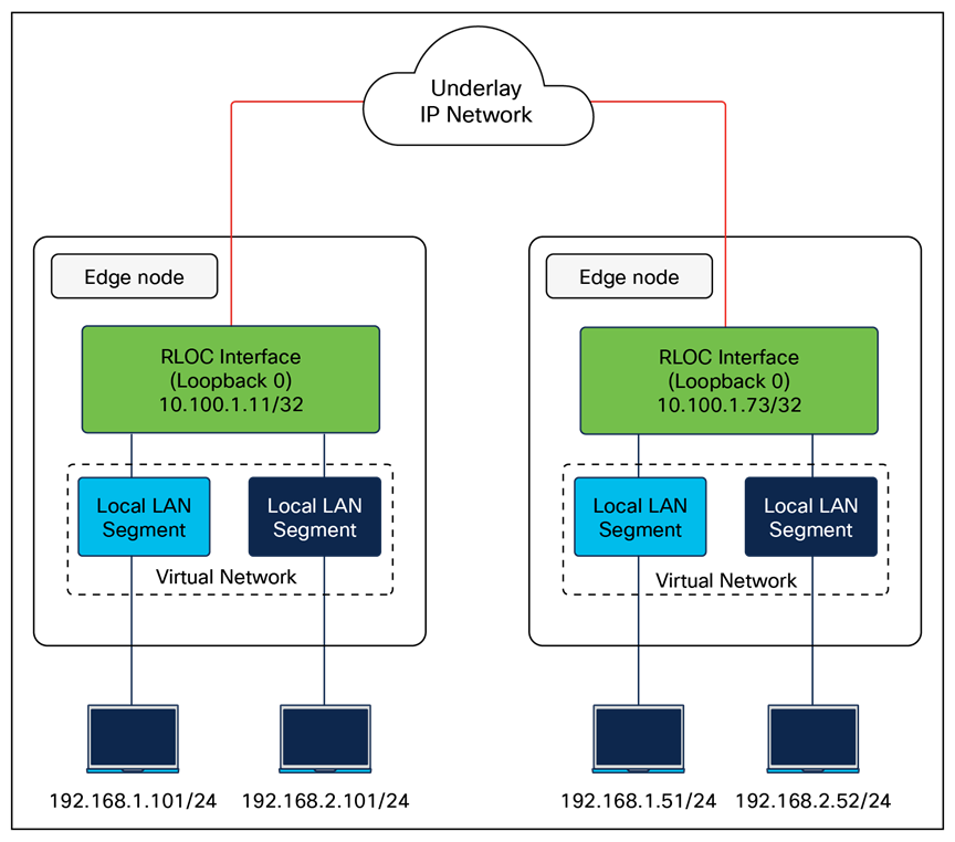
External border node – Example
A border node may also be connected to both known and unknown networks, such as being a common egress point for the rest of an enterprise network along with the internet. What distinguishes this border is that known routes, such as shared services and data center, are registered with the control plane node rather than using the default forwarding logic described above. This type of border node is sometimes referred to as an internal + external border node.
| Tech tip |
| Further design considerations for distributed campus deployments are discussed in the SD-Access for Distributed Campus reference model section. |
The key distinction between these border node types is the underlying routing logic that is used to reach known prefixes. Networks deployed similarly to the one shown in Figure 11 do not commonly import (register) routes with the control plane node. Because there is a common egress point to the fabric site, the border nodes are the destination for both known and unknown external routes. It is not necessary to register the known external prefixes in this type of design, as the same forwarding result is achieved for both known and unknown prefixes. Most deployments should provision a border node using the external border node type.
In Figure 13, both border nodes are connected to the internet and to the remainder of the campus network. Each border node is also connected to a separate data center with unique prefixes. If traditional default forwarding logic is used to reach these prefixes, the fabric edge nodes may send the traffic to a border not directly connect to the applicable data center. Traffic will have to inefficiently traverse the crosslink between border nodes. If the data center prefixes are imported into LISP, the edge nodes can send the traffic to the border node on the left to reach 203.0.113.0/24 and to the border node on the right to reach 198.51.110.0/24. Either border can be used as the default path to the internet.
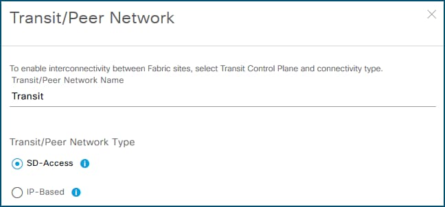
Internal + external border node example
| Tech tip |
| For further descriptions and discussions regarding how the Cisco Catalyst Center UI represents these three border node types, please see Guide to Choosing SD-Access Border Roles in Cisco Catalyst Center1.3.x on Cisco Community. |
Resiliency in border node deployments is generally achieved by pairing border nodes. By default, traffic is load balanced across the border nodes within a fabric site. Users have the option to configure border priority settings to control egress traffic, where a lower priority number indicates a more preferred border node for all virtual networks within a fabric site. Additionally, an optional BGP feature known as path prepending can be enabled on border nodes to influence ingress traffic by making certain borders preferred for advertised routes. The AS path prepending feature is disabled by default and can be selectively enabled to designate specific border nodes for incoming traffic or fallback purposes, distinct from the border priority, which affects how traffic egresses the fabric.
A border node may connect to a traditional Layer 2 switched access network. This allows the same IP subnet to exist in both the traditional network and the SD-Access network, with the border node performing the translation between these two networks and allowing them to communicate. This feature is called the Layer 2 border handoff and is discussed in depth in later sections.
Because this border node is connected to the traditional network, it is subject to the broadcast storms, Layer 2 loops, and spanning-tree problems that can occur in Layer 2 switched access networks. To prevent disruption of control plane node services or border node services connecting to other external networks, a border node should be dedicated to the Layer 2 handoff feature and not colocated with other fabric roles or services.
As mentioned in the Control Plane Node section, LISP Pub/Sub is recommended for new SD-Access deployments, enhancing resiliency by enabling new border node capabilities, including dynamic default border and LISP backup internet, which helps ensure that traffic is dynamically rerouted in case of changes to border nodes or the external routing topology. Multihoming data centers across multiple fabric sites connected to SD-Access transits is supported in the LISP Pub/Sub control plane, providing redundancy and load balancing for data center connectivity.
| Tech tip |
| In LISP Pub/Sub deployments, external or anywhere borders need a default route in the RIB (usually learned from a peer) so LISP can use it as a default route out of the SD-Access fabric. |
Fabric in a Box is an SD-Access construct in which the border node, control plane node, edge node, and optionally WLC are running on the same fabric node. This may be a single switch, a switch with hardware stacking, or a StackWise Virtual deployment. The embedded wireless controller is supported with Fabric in a Box. Fabric in a Box is discussed further in the Fabric in a Box Site Reference Model section.
Like other devices operating as edge nodes, extended nodes and access points can be directly connected to the Fabric in a Box. In locations where physical stacking is not possible due to the wiring structure, Fabric in a Box can support daisy-chaining of edge nodes, with careful capacity planning. In this daisy-chained topology, access points and extended nodes can be connected to any of the devices operating in the edge node role, including the Fabric in a Box itself. Dual Fabric in a Box is also supported, though it should be used only if mandated by the existing wiring structures. When Fabric in a Box is deployed as a StackWise Virtual pair, embedded wireless is supported from Catalyst Center 2.2.2.x onward for Catalyst 9400 and 9500/9500H platforms.
| Tech tip |
| Fabric in a Box is supported using a single switch, using a switch with hardware stacking, or with StackWise Virtual deployment. For specific platforms supported with StackWise Virtual in SD-Access networks, please see the Cisco Catalyst Center Release Notes. |
SD-Access extended nodes are Layer 2 switches that attach to a fabric edge node to extend SD-Access services to reach noncarpeted traditional areas of the business, often referred to as the extended enterprise. They provide connectivity and centralized management for IoT devices and traditional endpoints deployed in outdoor or industrial environments such as distribution centers, warehouses, and campus parking lots.
Extending fabric capabilities through extended nodes simplifies IoT operations by leveraging Cisco Catalyst Center automation, enforcing consistent policy across IT and OT networks, and improving end‑to‑end visibility for IoT devices. Extended nodes connect to a single fabric edge switch using an 802.1Q trunk configured as an EtherChannel with one or more physical links, except for supplicant-based extended nodes. Catalyst Center discovers these extended nodes through zero-touch Plug and Play, automates creation of the trunk and port channel, and then applies the same dynamic port-assignment methods used on edge nodes to provide macro-segmentation for attached endpoints.
Catalyst Center has three different support options for extended nodes: classic extended nodes, policy extended nodes, and supplicant-based extended nodes.
Classic extended nodes
Classic extended nodes provide Layer 2 port extension to a fabric edge node while keeping all fabric intelligence at or close to the fabric edge. They are Layer 2 switches that attach to the fabric edge node and rely on that edge for VXLAN, routing, SGT, and policy, while still being fully provisioned and monitored by Cisco Catalyst Center. Use this variant when simple Layer 2 extension is enough without micro-segmentation capabilities
SD-Access extended node capabilities are supported on the platforms listed in the Compatibility Matrix. Extended nodes support AAA configuration on their host-connected ports, which allows endpoints to be authenticated and authorized with ISE. Dynamic VLAN assignment places the endpoints into specific VLANs based on endpoint attributes and credentials presented. This VLAN is associated with a VRF instance on the upstream edge node, creating the first layer of segmentation. SGT assignment, the second layer of segmentation, is provided within Cisco Catalyst Center through VLAN-to-SGT mappings on the edge node.
When deploying extended nodes, consideration should be taken for east-west traffic in the same VLAN on a given extended node. This east-west traffic is forwarded using traditional Layer 2 forwarding logic. Inter-VLAN traffic is attracted to the edge node because the anycast gateway for the end hosts resides there. When a host connected to an extended node sends traffic to destinations in the same virtual network connected to or through other fabric edge nodes, segmentation and policy are enforced through VLAN-to-SGT mappings on the fabric edge node.
| Tech tip |
| For enhanced security and segmentation scalability, consider using the policy extended node because security group enforcement can be executed at the ingress point in the network. |
Policy extended nodes
Building upon classic extended nodes, policy extended nodes (PENs) are onboarded as “extended nodes” but enhanced to support inline SGT tagging and SGACL enforcement on access ports and toward the fabric edge, bringing full fabric segmentation and SGT-based controls. It still uplinks via an 802.1Q trunk/port channel to a single fabric edge, which provides VXLAN encapsulation, LISP registration, and anycast gateway services.
Both VLAN and SGT can be assigned dynamically as a result of the endpoint authentication and authorization process. This allows traffic between sources in the same VLAN and in different VLANs to be enforced on the policy extended node itself. Segmentation to other sources in the fabric are provided through inline tagging on the 802.1Q trunk connected to the upstream fabric edge node.
Use this variant when granular TrustSec capabilities are needed within the node.
Additional enhancements are available to devices operating as PENs. This capability is supported on the platforms listed in the Compatibility Matrix.
Supplicant-based extended nodes
Supplicant-based extended nodes (SBENs) are another flavor of extended node that can be used where secure onboarding of network devices is critical. With SBENs, Cisco SD-Access can enforce secure onboarding of the extended node using IEEE 802.1X mechanisms. This helps ensure that unauthorized devices cannot connect to the network by maintaining closed authentication on all edge node access ports.
SBENs are provisioned as policy extended nodes by Cisco Catalyst Center. They have a supplicant with Extension Authentication Protocol — Transport Layer Security (EAP-TLS) authentication on their uplink to the edge node. The EAP-TLS certificate is provided by Catalyst Center using the Catalyst Center certificate authority. After successful onboarding, access to the edge node port is based solely on authentication status. If the device or port goes down, the authentication session is cleared and traffic is not allowed on the port. When the port comes back up, it undergoes 802.1X authentication to regain access to the SD-Access network.
Use this variant when closed authentication is enabled for the fabric site and secure zero‑touch onboarding of the switch is the primary requirement. Catalyst 9200 and 9300 Series platforms can operate as SBENs.
Extended node design
Dual homing of extended nodes and policy extended nodes is supported via MEC to an upstream StackWise or StackWise Virtual. Alternatively, Flexlink+ uplinks to different edge nodes can be deployed such that the uplink is active to only one fabric edge node at a time. Flexlink+ configuration must be deployed using Catalyst Center templates. Fabric access points cannot be connected to Flexlink+ extended nodes, and SBENs cannot be dual-homed. Be sure to confirm that the extended node switch model selected supports Flexlink+.
Except for the Flexlink+ fabric access point restriction, access points and other PoE devices can be connected directly to all variants of extended node switches. When connecting PoE devices, ensure that enough PoE power is available. This is especially true with Industrial Ethernet switches, which have a significant variety of different powering options for both AC and DC circuits.
The SGT value 8000 is used on the ports between the policy extended node and the edge node. It should not be reused elsewhere in the deployment. The SGT value 8000 will be assigned only if no CMD field is received on an interface, or if the trusted keyword is not present. Inline SGT tagging between these ports is configured as trusted; therefore, both a classified source SGT and an SGT value of 0 (unknown) received in the CMD field are considered trusted.
SD-Access extended nodes support both daisy-chain and ring topologies, using either all classic extended nodes or all policy extended nodes; mixing the two types in the same chain or ring is not supported. A single daisy chain can include up to three Catalyst 9000 devices or alternatively up to 18 IE devices. Additionally, daisy chains can start with a PEN followed by an SBEN. These options provide flexible ways to connect different extended-node types in a fabric network, with each device onboarded according to its license level. For example, an IE3400/IE3500 Series switch that could operate as a PEN is onboarded as a classic extended node when running only the Essentials license, and if a device has multiple neighbors with differing license levels, it is treated as a classic extended node regardless of its own license.
Catalyst 9300, 9400, and 9500/9500H fabric edge nodes support attachment of downstream extended nodes. Extended nodes cannot be attached to other edge node hardware platforms, such as the Catalyst 9200, IE9300, or IE3500 Series.
Resilient Ethernet Protocol (REP) rings are supported through extended nodes and policy extended nodes for industrial Ethernet devices. Ring of rings is not supported, and by default a maximum of 18 extended nodes can be configured in a ring. REP rings should consist solely of either all extended nodes or all policy extended nodes, while ring topologies of Catalyst 9000 edge nodes, PENs, or SBENs are not supported. Dynamic addition of IE or PEN endpoints to an existing REP ring is not supported. SD-Access supports a single REP ring that both starts and ends on the same fabric edge node. Please refer to the compatibility matrix for further details.
| Tech tip |
| For further details on Cisco IoT solutions and the associated Cisco Validated Designs, please see the Cisco Extended Enterprise Non-Fabric and SD-Access Fabric Design Guide and visit https://www.cisco.com/go/iot. |
SD-Access provides multiple deployment models for connecting wireless networks to the wired fabric. Depending on customer requirements, operational models, and infrastructure readiness, wireless can be deployed using one of the following modes:
● Fabric-enabled wireless
● Over-the-top (OTT) wireless
● Mixed-mode wireless
● FlexConnect wireless
Please refer to the Non-Fabric Wireless Design section to understand the non-fabric deployment modes. The design section also outlines the advantages and considerations associated with each deployment mode.
SD-Access supports two options for connecting wireless access to SD-Access fabric. The first option uses a traditional Cisco Unified Wireless Network local-mode deployment running over the top as a nonnative service. In this mode, the SD-Access fabric acts purely as a transport for Control and Provisioning of Wireless Access Points (CAPWAP) tunnels between access points and WLCs, which is particularly useful during migration phases. The second option is fully integrated fabric-enabled wireless, in which access points and wireless clients become part of the fabric overlay so that SD-Access capabilities such as virtual network and security group policy extend consistently to both wired and wireless endpoints.
Integrating the WLAN into the fabric provides the same advantages to wireless clients that the fabric provides to wired clients, including simplified addressing, mobility with stretched subnets, and end-to-end segmentation with consistent policy enforcement across the wired and wireless domains. The fabric-enabled wireless integration also enables the WLC to offload data plane forwarding responsibilities to the fabric while continuing to operate as the control plane for the wireless domain.
Fabric WLCs manage and control the fabric-mode access points using the same general model as the traditional local-mode controllers, which offers the same operational advantages such as mobility control and radio resource management. A significant difference, with SD-Access, is that client traffic from wireless endpoints is not tunneled from the APs to the WLC. Instead, communication from wireless clients is encapsulated in the VXLAN by the fabric APs, which build a tunnel to their first-hop fabric edge node. Wireless traffic is therefore sent to the edge nodes, which deliver fabric services including the Layer 3 anycast gateway, policy enforcement, and traffic handling, enabling a distributed data plane with integrated SGT capabilities. As a result, traffic forwarding follows the optimal path across the SD-Access fabric to the destination while maintaining consistent policy, independent of whether the endpoint is wired or wireless.
AP control plane communication still uses a CAPWAP tunnel to the WLC, mirroring the traditional Unified Wireless Network control plane model. In an SD-Access deployment, however, the fabric WLC also participates in the SD-Access control plane through LISP. When the controller is added as a fabric WLC, it establishes LISP control plane sessions with the fabric control plane nodes.
This communication allows the WLCs to register client Layer 2 MAC addresses, SGTs, and Layer 2 segmentation information (Layer 2 VNI). All of this works together to support wireless client roaming between APs across the fabric site. The SD-Access fabric control plane process inherently supports the roaming feature by updating its host-tracking database when an endpoint is associated with a new RLOC (wireless endpoint roams between APs).
Fabric-enabled wireless provides native integration of wireless into the SD-Access fabric and is the recommended deployment model. In such deployments both the WLC and AP are fabric enabled.
Fabric wireless integration design
Fabric-mode access points connect into a predefined virtual network named INFRA_VN. The VN is associated with the global routing table. This design allows the WLC to communicate with the fabric site for AP management without needing to leak routes out of a VRF table.
| Tech tip |
| INFRA_VN is also the VN used by extended nodes for connectivity. |
When integrating fabric-enabled wireless into the SD-Access architecture, the WLC control plane keeps many of the characteristics of a local-mode controller, including the requirement to have a low-latency connection between the WLC and the APs. This latency requirement, 20 ms RTT, precludes a fabric WLC from managing fabric-mode APs at a remote site across a typical WAN. As a result, a remote site with SD-Access Wireless with a WAN circuit exceeding 20 ms RTT will need a WLC that is local to that site.
Wireless integration with SD-Access should also consider WLC placement and connectivity. WLCs typically connect to a shared services distribution block that is part of the underlay. The preferred services block design has chassis redundancy as well as the capability to support Layer 2 MEC for link and platform redundancy to the WLCs.
In the simplified example below, the border nodes are directly connected to the services block switch with Layer 3 connections. The WLCs are connected to the services block using link aggregation. Each WLC is connected to a member switch of the services block logical pair.
In a fabric-enabled wireless deployment, the WLC supports a maximum of two LISP sessions within a fabric site. As a result, in fabric-enabled wireless deployments, the number of fabric control plane nodes is limited to two within a fabric site.

Simplified WLC, services block, and border node topology
Fabric-mode access points
The fabric-mode access points are Cisco Wi-Fi 7 (802.11be), WI-Fi-6 (802.11ax), and 802.11ac Wave 2 APs associated with the fabric WLC that have been configured with one or more fabric-enabled SSIDs. Fabric-mode APs continue to support the same wireless media services that traditional APs support, such as applying Application Visibility and Control (AVC), QoS, and other wireless policies. Fabric APs establish a CAPWAP control plane tunnel to the fabric WLC and join as local-mode APs. They must be directly connected to the fabric edge node or extended node switch in the fabric site. For their data plane, fabric APs establish a VXLAN tunnel to their first-hop fabric edge switch, where wireless client traffic is terminated and placed on the wired network.
Fabric APs are considered a special-case wired host. Edge nodes use Cisco Discovery Protocol to recognize APs as these wired hosts, apply specific port configurations, and assign the APs to a unique overlay network called INFRA_VN. As wired hosts, APs have a dedicated EID space and are registered with the control plane node. This EID space is associated with the predefined INFRA_VN overlay network in the Catalyst Center UI. It is a common EID space (prefix space) and common virtual network for all fabric APs within a fabric site. The assignment to this overlay virtual network allows management simplification by using a single subnet to cover the AP infrastructure at a fabric site.
Refer to the SD-Access Wireless Design and Deployment Guide for information on how to onboard fabric APs with different site authentication templates.
Secure AP Onboarding
Cisco Secure AP Onboarding provides a controlled and secure method to onboard wireless access points into an SD-Access environment. By enforcing 802.1X authentication on access points connected to fabric edge (EN), extended node (EX), policy extended node (PEN), and supplicant-based extended node (SBEN) devices, it protects the network from unauthorized AP attachment.
During onboarding, APs receive strictly limited access, allowing only DHCP, DNS, and Cisco Catalyst Center connectivity to support the Plug-and-Play workflow. Catalyst Center enhances the PnP process by automatically enabling the 802.1X supplicant on the AP and serving as the certificate authority to issue device certificates. Limited-access authorization policies must be configured manually on Cisco ISE.
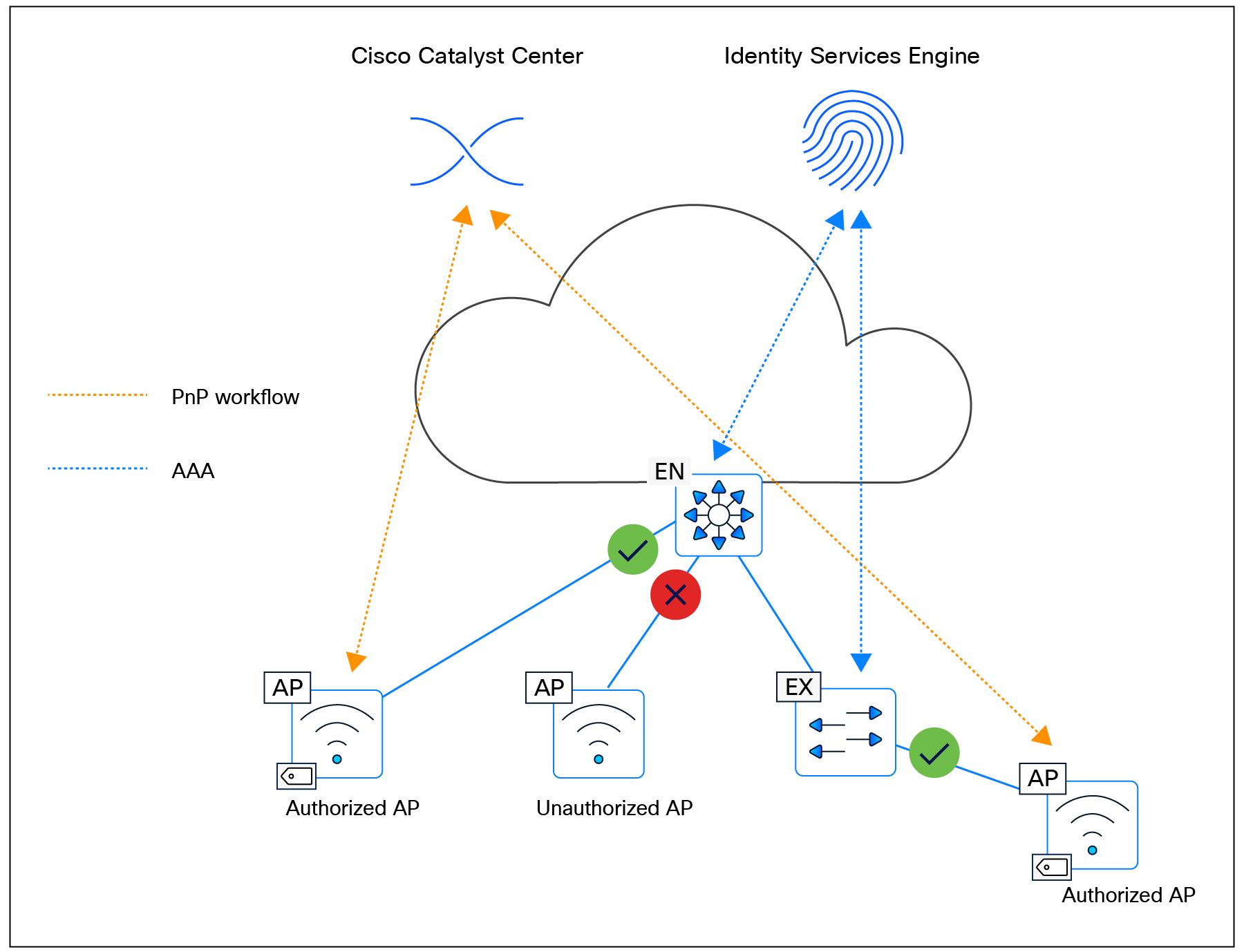
Secure AP Onboarding
SD-Access Wireless platform support
The SD-Access Wireless architecture is compatible with a range of WLCs and access points. For the most current and comprehensive list of supported devices and software, please refer to the SD-Access Compatibility Matrix
WGB in Cisco SD-Access deployments
A workgroup bridge (WGB) is a Cisco access point configured to operate as a wireless client while providing Layer 2 connectivity to devices connected on its Ethernet interfaces. In an SD-Access deployment, WGB support—available in Cisco Catalyst Center Release 2.3.7.x and later and requiring Cisco IOS XE 17.12.1 or later—enables fabric connectivity to be extended to remote locations where edge node or extended node switches cannot be deployed. The WGB connects to a fabric SSID and extends the fabric network to its Ethernet ports, with all downstream endpoints inheriting the same virtual network and SGT as the WGB. It supports open, pre-shared keys (PSK), and 802.1X SSIDs and can function as an authenticator, using EAP toward connected endpoints and RADIUS toward the AAA server. As authentication timers are fixed, network latency between the WGB and the RADIUS server must remain within acceptable limits to prevent retransmissions. WGB configuration is not automated through Catalyst Center and must be applied manually via the command-line interface (CLI), although CCX Aironet—required for WGB association—can be enabled through the Model Config Editor. Wireless clients behind a WGB are not supported.
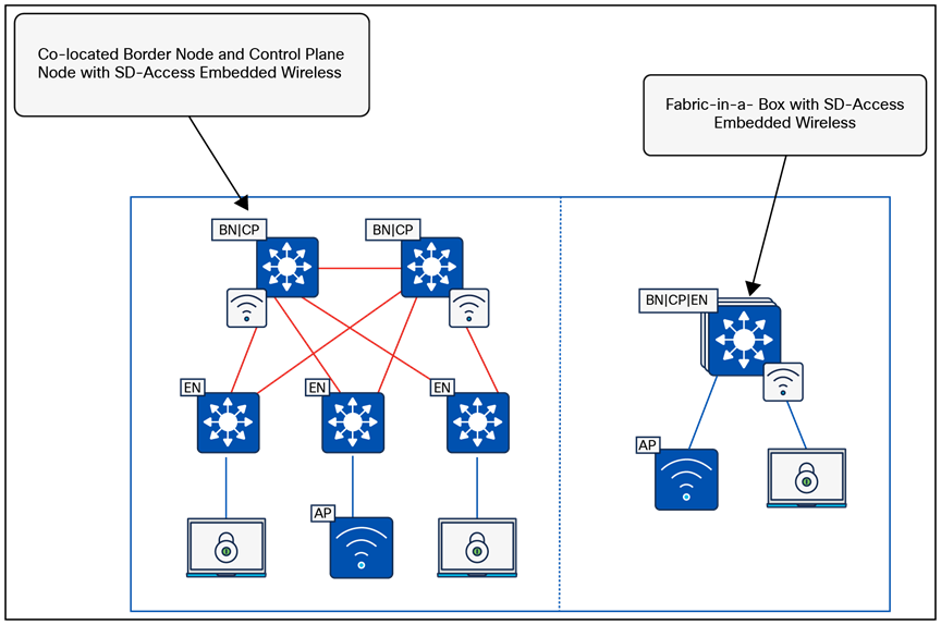
WBG in SD-Access deployment
Mesh integration in Cisco SD-Access
Mesh networking in Cisco SD-Access addresses the need to extend secure, segmented wireless connectivity into areas where Ethernet cabling is difficult or impossible to deploy—such as outdoor campuses, temporary installations, remote yards, and industrial zones. By enabling wireless backhaul links between access points, mesh provides flexible coverage expansion, rapid deployment, and resilient connectivity through self-forming and self-healing topology. This helps ensure operational continuity when wired uplinks are unavailable or costly to implement, while maintaining the full benefits of SD-Access segmentation and policy.
Mesh support within SD-Access allows fabric SSIDs to be extended from indoor spaces to outdoor wireless mesh domains without compromising segmentation or policy enforcement. This capability is available starting with Cisco Catalyst Center Release 2.3.7.x and requires the fabric wireless infrastructure to operate on IOS XE 17.12.1 or later. The workflow is fully automated through Catalyst Center. In this architecture, root access points (RAPs) and mesh access points (MAPs) function in bridge mode but are classified as fabric APs. Wireless endpoints connecting through RAPs or MAPs receive the same virtual network and SGT segmentation that they would receive when joining a fabric SSID on any other fabric AP. All hardware and virtual form factors of the Cisco Catalyst 9800 Series WLCs are supported, while the Embedded Wireless Controller on Catalyst 9000 switches is not. Mesh functionality is available on Wave 2 and Catalyst APs capable of mesh operation.
RAPs and MAPs establish CAPWAP tunnels to the WLC using standard discovery mechanisms and support seamless wireless client roaming across mesh nodes. Each RAP and MAP forms a VXLAN access tunnel to its fabric edge node. MAPs always anchor to the same fabric edge as their parent RAP, maintaining Layer 2 adjacency so that client traffic is converted from 802.11 to 802.3 and transported through VXLAN to the fabric edge. RAPs connect to the fabric edge directly or via EN/EX nodes, while MAPs attach through a wireless backhaul link to a parent RAP or MAP. MAPs operating in fabric mode can roam only across RAP/MAP nodes associated with the same fabric edge; roaming across nodes linked to different fabric edges is not supported. However, wireless clients can roam across RAPs and MAPs even when those APs terminate on different fabric edges.
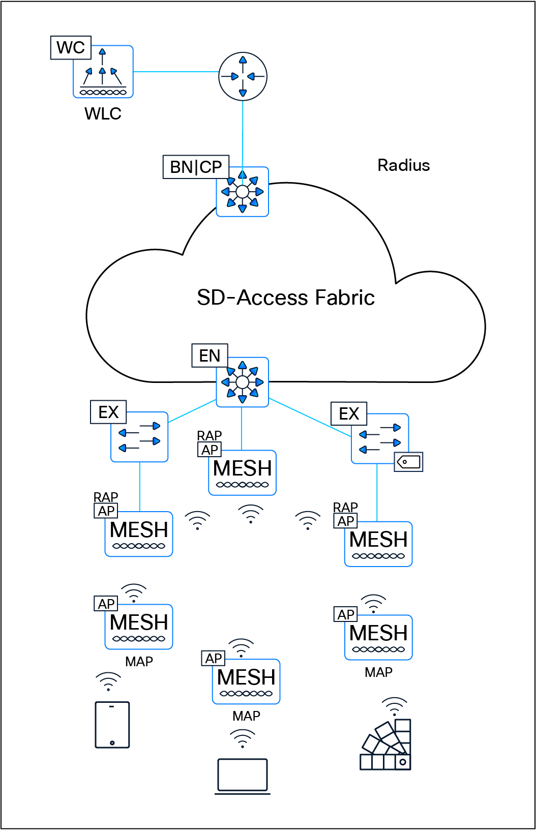
Mesh integration in SD-Access
Cisco Remote LAN (RLAN) fabric integration
Cisco Remote LAN (RLAN) provides Catalyst access points the ability to extend wired LAN connectivity to remote endpoints via their local Ethernet ports. Unlike typical wireless clients, an AP configured for RLAN uses its wireless or wired backhaul to transport traffic from the RLAN port back to the network via a WLC. This enables wired endpoints—such as printers, cameras, IoT devices, or point-of-sale systems—that do not support Wi-Fi to gain LAN access without requiring physical cabling to the nearest switch. RLAN is especially useful in environments where installing Ethernet infrastructure is difficult or costly, such as warehouses, dormitories, hospitality venues, outdoor areas, retail spaces, and temporary deployments. Traffic entering the AP through an RLAN port is encapsulated in CAPWAP and sent to the WLC, where VLANs, access control lists (ACLs), QoS, and other policy constructs are applied. This helps ensure consistent segmentation and security for RLAN-attached devices, comparable to centrally controlled wireless clients.
In SD-Access environments, RLAN fabric extends the fabric network directly to an AP’s RLAN port, enabling remote wired endpoints to seamlessly participate in the same virtual network and segmentation model as devices connected to a fabric edge, extended node, or policy extended node. This is especially useful for endpoints that cannot be connected directly to a fabric edge switch.
RLAN fabric is commonly deployed in universities, dormitories, hotels, and other hospitality environments, supporting devices such as gaming consoles, printers, media devices, and IoT endpoints that require consistent LAN connectivity but are far from wired infrastructure. RLAN clients do not support QoS/differentiated services code point (DSCP) remarking, multicast, or broadcast traffic. The feature is supported on Cisco Catalyst 9800 Series platforms but not on AireOS platforms. In fabric mode, the AP inserts the SGT into the VXLAN header and forwards traffic through the access tunnel to the fabric edge. Mixed-mode configurations are also supported, allowing one port to operate in fabric mode while another functions in central switching mode.
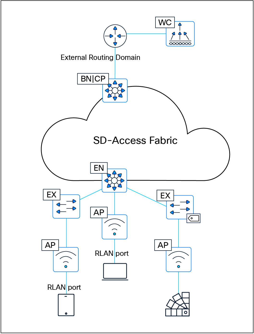
Remote LAN fabric integration
| Tech tip |
| For additional information and details on wireless operations and communications with SD-Access Wireless, fabric WLCs, and fabric APs, please see the SD-Access Wireless Design and Deployment Guide. |
SD-Access Embedded Wireless Controller on Catalyst 9000 switches
To enable wireless controller functionality without a hardware WLC in distributed branches and small campuses, the Cisco Embedded Wireless Controller (EWC) is available for Catalyst 9000 switches as a software package on switches running in Install mode. The wireless control plane of the EWC operates like a hardware WLC. CAPWAP tunnels are initiated on the APs and terminate on the EWC. The data plane uses VXLAN encapsulation for the overlay traffic between the APs and the fabric edge node.
The EWC is supported ONLY for SD-Access deployments with a few topologies:
● Cisco Catalyst 9000 switches functioning as colocated border and control plane nodes. Furthermore, embedded wireless functionality can be activated on a Cisco Catalyst 9000 switch edge node when the border and control plane nodes are positioned on a routing platform.
● Cisco Catalyst 9000 switches functioning as a Fabric in a Box.
| Tech tip |
| All Catalyst 9000 switches support the SD-Access embedded wireless functionality with the exception of the Catalyst 9200, 9200L, 9500X, and 9600 Series Switches. The EWC supports only fabric-mode APs used in SD-Access deployments. |
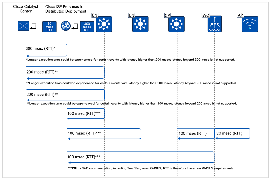
SD-Access embedded wireless supported topologies
AAA Server per SSID
The AAA Server per SSID feature was introduced in Cisco Catalyst Center Release 2.2.1. Prior to this release, the AAA servers used by an SSID were defined under Design > Network Settings, where only two AAA servers could be configured. These servers were shared across both wired and wireless networks, with no option to assign a unique AAA server set to a specific SSID.
With the introduction of this feature, administrators can now assign up to six AAA servers per SSID, providing significantly greater flexibility.
The AAA servers configured for an SSID may include a combination of ISE Policy Service nodes (PSNs) and traditional AAA servers. This flexibility allows administrators to create distinct AAA server groups—for example, one set for enterprise SSIDs and another for guest SSIDs—aligning with common best practices for isolating trusted and untrusted user authentication.
Administrators also have the option to override the AAA server configuration for an SSID at any level of the site hierarchy (floor, building, or sublocation). When such an override is applied, Catalyst Center provisions multiple SSIDs with the same name but different profile names, depending on where the override occurred.
This feature is supported on both AireOS controllers and Catalyst 9800 Series Wireless LAN Controllers. Support for the EWC on Catalyst 9000 switches began with Catalyst Center Release 2.2.2.
For AireOS-based controllers, the maximum number of global AAA servers supported on the platform is 32. Therefore, the total number of AAA servers configured across all SSIDs must not exceed this limit; exceeding it will result in provisioning failure.
The AAA Server per SSID feature applies only when the SSID security configuration requires authentication and authorization. Any change to the AAA server configuration for an SSID requires the WLC to be reprovisioned for the updated settings to take effect.
High availability in SD-Access Wireless
The most critical component of the SD-Access Wireless solution is the WLC. The WLC supports high availability (HA) and Stateful Switchover (SSO) when operating in fabric mode.
Controller redundancy
Controller high availability is supported using both N+1 and SSO.
Stateful redundancy with SSO
● The WLC SSO pair is seen as a single node by the fabric.
● Only the active WLC interacts with the fabric control plane (CP) node.
● Fabric configuration and CP state are synchronized between the active and standby WLCs.
● Upon failure, the new active WLC performs a bulk update of fabric clients to the CP.
● Access points and clients remain connected, helping ensure seamless operation with no disruption in client traffic.
● In EWC deployments, HA SSO is supported within the switch stack, but not across stacks.
Stateless redundancy with N+1
● N+1 redundancy is supported for environments requiring simpler HA configurations.
● APs are configured with primary and secondary WLCs.
● APs and associated clients register with the primary WLC.
● Upon primary WLC failure, the AP disconnects and joins the secondary WLC.
● Clients also disconnect and register with the secondary WLC.
● The secondary WLC performs new client registration with the CP.
● In EWC deployments, N+1 HA is supported across switches or switch stacks.
Combining HA-SSO and N+1
Customers can choose a combination of HA-SSO and N+1 for environments requiring higher resiliency:
● WLCs in HA-SSO mode can serve as primary and secondary controllers for different locations.
● Each WLC can also act as a backup for other WLCs in the network. For example, WLC1 can be the primary controller for a floor in a building while WLC2 acts as the secondary; on another floor, their roles can be reversed.
Mobility considerations in N+1 mode
To achieve seamless roaming in the fabric, all client roams are treated as Layer 2 roams. A mobility relationship must be established between WLCs operating in N+1 mode:
● For deployments involving a combination of physical and virtual WLCs, the mobility workflow in Catalyst Center can be used to configure mobility peering and ensure smooth client roaming.
● For EWC on the Catalyst 9000 switch, mobility peering is fully automated by Catalyst Center once the primary and secondary roles are assigned.
WLC scaling considerations in SD-Access fabric
An SD-Access fabric can support multiple WLCs within the same fabric site. This allows large or distributed environments—such as a campus comprising multiple buildings—to assign different WLCs to manage different buildings or operational zones. For example, one WLC may be dedicated to building A, another to building B, and so forth.
These controllers can also be deployed in an N+1 HA model, where each WLC is configured with primary and secondary roles, allowing them to back up one another. In the event of a WLC failure, access points and clients can fall back to the designated secondary controller to maintain service continuity.
In deployments using EWCs on Catalyst 9000 switches, the scalability model is more restricted. A maximum of two EWCs can operate within a single SD-Access fabric site. The EWCs can be paired in an N+1 arrangement, but only within this two-controller limit.
From a design perspective, using multiple WLCs—physical, virtual, or embedded—provides improved distribution of load, better operational segmentation, and enhanced resiliency. The key considerations include:
● Controller placement: WLCs should be located onsite and within low-latency proximity to the APs (typically <20 ms).
● Mobility domain design: When multiple WLCs coexist, mobility relationships must be established to support seamless roaming, especially in N+1 deployments.
● Role assignment: Carefully design which WLC serves as primary and backup for each building or floor to balance failover capacity.
● EWC limitations: EWCs are ideal for smaller or distributed environments but should not be used where more than two controllers are required per fabric site.
This architecture enables scalable, resilient wireless services that integrate seamlessly with SD-Access fabric operations.
When designing for guest wireless, SD-Access supports three different models:
● Guest as a dedicated VN: Guest is simply another user-defined virtual network.
● Multisite remote border: Multisite remote border allows the same IP address pool to exist at multiple fabric sites by anchoring the pool to specific border nodes and control plane nodes.
● WLC guest anchor using a centrally switched guest SSID: This model leverages the legacy centralized wireless method of supporting guest access using the guest anchor WLC in the DMZ. This is explained in the Nonfabric Wireless Design section.
Guest as a dedicated VN
Creating a guest virtual network is as straightforward as creating a VN in Cisco Catalyst Center.
With the guest as VN model, guest and enterprise clients share the same control plane node and border node. The guest SSID is associated to a dedicated guest VN, and SGTs are used to isolate guest traffic from itself. Guests, by the nature of VRFs and macro-segmentation, are automatically isolated from other traffic in different VNs, though the same fabric nodes are shared for guest and nonguest users.
Guest users should be assigned an SGT value upon connecting to the network. This assignment is used to implement the equivalence of a peer-to-peer blocking policy. For a fabric SSID, all security policy is enforced at the edge node, not at the access point itself. Traditional peer-to-peer blocking, which is enabled on the WLAN in the WLC, would not take effect. To provide consistent policy, an AP will forward traffic to the fabric edge, even if the clients communicating are associated with the same AP. An SGT assigned to guest users can be leveraged to deny traffic between the same SGTs.
When designing a guest VN, the same design modalities referenced throughout this document for any other virtual network apply to the guest VN.
Multisite remote border
This design leverages a dedicated control plane node and border node for guest traffic. The nodes can be colocated on the same device for operational simplicity, or on separate devices for maximum scale and resilience. This functionality provides a simplified way to tunnel the guest traffic to the DMZ, which is a common security convention.
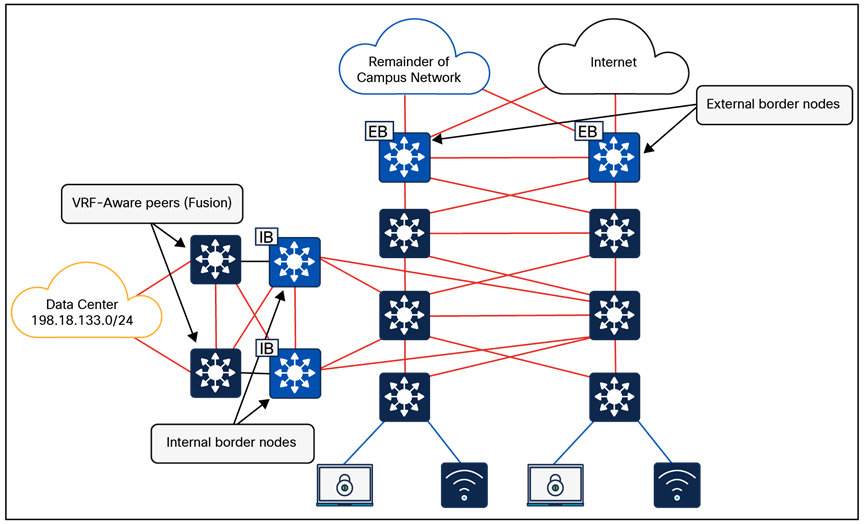
Multisite remote border
A multisite remote border enables a virtual network to be available across multiple fabric sites, and the same subnet that is associated with the VN can be spread across sites. In this VN all traffic between fabric to nonfabric must route through the multisite remote border.
● Both enterprise (nonguest) and guest traffic is encapsulated in VXLAN at the access point and sent to the edge node. For enterprise traffic the edge node is configured to use the fabric site border nodes and control plane nodes, and for guest traffic the edge node is configured to use the multisite remote border and control plane nodes. The multisite remote border commonly resides in a DMZ to provide complete isolation of guest traffic from the enterprise traffic.
● Any virtual network (not just guest) can be anchored if egress traffic needs to exit the network at a specific location (site).
● The anchored VN is first deployed at one fabric site (anchor site).
● The anchor site defines the border and control plane node for the anchored VN.
● The anchored VN exists at other fabric sites (anchoring sites) and sends traffic to the anchor site.
● The VXLAN cannot be fragmented (DF-bit set); the MTU between the anchor site and anchoring sites must be sufficient.
● Each fabric node hosting an anchored VN must have a /32 RIB entry for all other fabric nodes hosting the same anchored VN.
● Seamless wireless roaming between fabric sites is supported for an SSID attached to an IP pool on the anchored VN. The administrator must enable mobility between the WLCs across fabric sites using the mobility workflow on Cisco Catalyst Center.
● The Aire-OS-based WLC can communicate with control plane nodes across two fabric sites when the deployment uses the multisite remote border functionality.
● The Catalyst 9800 Series WLC can communicate with up to 16 fabric sites. This includes the local fabric site and up to 15 additional distinct fabric sites when using multisite remote border functionality.
● Multicast routing is supported within an anchored VN.
● The number of remote fabric edge nodes participating in a multisite remote border (considering all anchoring sites) should be less than 1000.
FlexConnect wireless on SD-Access fabric
FlexConnect (local switching) within an SD-Access environment is supported using intra-subnet routing (ISR), introduced in Cisco Catalyst Center Release 2.3.5.x.
Capabilities
● FlexConnect and Meraki® local switching are supported through ISR.
● ISR is suitable for remote sites or branch sites requiring local traffic switching.
ISR is not suitable for deployments that need Layer 2 connectivity between access points. Certain implementations (such as those from some third-party wireless vendors) require Layer 2 connectivity to ensure fast roaming, and ISR can’t meet those requirements.
Limitations
● There is no support for IPv6 endpoints and Layer 2 virtual networks.
Transits are an SD-Access construct that defines how Cisco Catalyst Center will automate the border node configuration for the connections between fabric sites or between a fabric site and the external world. This connectivity may be a MAN, WAN, or internet. The WAN could be MPLS, SD-WAN, or other WAN variations.
IP-based transits: Packets are de-encapsulated from the fabric VXLAN into native IP. Once in native IP, they are forwarded using traditional routing and switching modalities. IP-based transits are provisioned with VRF-lite to connect to the upstream device. IP-based transits are commonly used to connect to shared services using a VRF-aware peer and to connect to upstream routing infrastructure or firewall for connectivity to WAN and the internet. BGP is used between the border and upstream routing infrastructure to distribute routes. Catalyst Center fully automates BGP, VRF-lite, and border handoff interface configurations on SD-Access border nodes. Configuration of the peer devices has to be handled by the network administrator. With IP-based handoffs, SGT tags are not copied over from VXLAN to IP headers.
SD-Access transits: SD-Access transits are exclusively used in SD-Access for Distributed Campus. In this model, the same control, data, and management plane is used end to end, interconnecting multiple fabric sites. In an SD-Access transit, packets are encapsulated between fabric sites using the VXLAN encapsulation. This natively carries the macro (VRF) and micro (SGT) policy constructs between fabric sites. SD-Access transit supports two control plane architectures: LISP Pub/Sub (recommended) and LISP/BGP. SD-Access transit requires transit control plane nodes, which:
● Are dedicated fabric roles that cannot be colocated with other fabric roles.
● Must be IP reachable by every fabric site external border node.
● Are recommended to be out of the data forwarding path between fabric sites.
● Are usually deployed in duplicate for high availability: up to four for LISP Pub/Sub, or up to two for LISP/BGP.
● Must match the control plane architecture of connected fabric sites; for example, LISP Pub/Sub fabric sites can only connect to a LISP Pub/Sub SD-Access transit.
Transit control plane nodes operate in the same manner as site-local control plane nodes except that they service multiple fabric sites. They are required only when using SD-Access transits.
Each fabric site will have its own site-local control plane nodes for intrasite communication, and transit control plane nodes for intersite SD-Access transit communication. Transit control plane nodes provide the following functions:
● Site aggregate prefix registration: Border nodes (with external border functionality) connected to the SD-Access transit use LISP map-register messages to inform the transit control plane nodes of the aggregate prefixes associated with the fabric site. This creates an aggregate HTDB for all fabric sites connected to the transit. Rather than a host route being associated with a routing locator (EID-to-RLOC binding), which is what occurs in a site-local control plane node, the transit control plane node associates the aggregate prefix with a border node’s RLOC.
● Control plane signaling: Once aggregate prefixes are registered for each fabric site, control plane signaling is used to direct traffic between the sites. When traffic from an endpoint in one fabric site needs to be sent to an endpoint in another fabric site, either the transit control plane is queried in LISP/BGP or the prefix-to-RLOC mapping is published to the border node in the case of LISP Pub/Sub. The border node then uses this information to steer the traffic to the border of the other fabric site that has registered the prefix with the transit control plane.
The transit control plane node is used only to publish or distribute fabric prefixes between different fabric sites and is not in the data path of traffic sent from one site’s border node to the other site’s border node.
A fabric site is a logical construct in the Catalyst Center UI that consists of a distinct set of network devices operating in fabric roles. In most implementations a fabric site contains control plane nodes, border nodes, edge nodes, and fabric WLCs. The control plane node is a mandatory component. A border node facilitates communication to destinations outside of the fabric site. An edge node is required to connect endpoints. A fabric WLC integrates wireless with the fabric.
Cisco SD-Access fabric zones are an optional construct within a fabric site that provides granular control over how VNs and IP pools are provisioned within a fabric site. Fabric zones are particularly valuable for customers who must restrict certain VNs/IP pools to specific groups of fabric edge switches and extended nodes.
Fabric zone design considerations:
● By default, no fabric zones exist in a fabric site; they must be created by the administrator. Fabric zones can be created at the area or building or floor level. Fabric zones flow down the design hierarchy. For example, if created at the area level, all buildings and floors under that area automatically become part of the same zone.
● Fabric zones can be enabled during day-0 or day-N operations:
◦ Day 0: The zone starts empty with no associated VNs/IP pools; these must be added explicitly via workflow.
◦ Day N: The zone initially inherits all VNs from the parent fabric site, and the administrator must remove the VNs/IP pools that should not apply within the zone.
● Edge nodes and extended nodes within a fabric zone automatically implement all anycast gateways and Layer 2 VNs configured within the fabric zone.
● A border node, control plane node, and fabric WLC can each be provisioned to an area/building/floor that is part of a fabric zone, and the fabric zone will not impact the configuration of border nodes, control plane nodes, or WLCs. Fabric zones influence only the configuration of edge node and extended node switches.
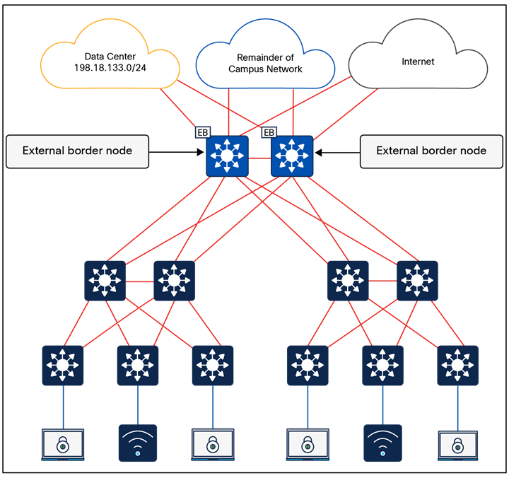
Fabric zones
| Tech tip |
| For the number of fabric sites supported based on appliance size, please refer to the Cisco Catalyst Center Data Sheet Appliance Scale and Hardware Specifications. |
Platform roles and capabilities
The SD-Access network platforms should be chosen based on the capacity and capabilities required by the network, considering the recommended functional roles. Refer to the SD-Access Hardware and Software Compatibility Matrix for the most up-to-date details about the platforms and software supported for each version of Cisco SD-Access.
This section is organized into the following subsections:
| Section |
Subsection |
| Nonfabric wireless design |
Over-the-top (OTT) wireless
OTT wireless refers to a deployment where the wireless infrastructure (WLC and APs) is not integrated with the SD-Access fabric, which means they operate as nonfabric WLC and nonfabric APs. Wireless client traffic is carried “over the top” of the fabric as regular IP traffic.
Compared to fabric-enabled wireless, OTT wireless complicates or in some cases trades away valuable network capabilities:
● Common wired and wireless macro- and micro-segmentation policy enforcement
● Common wired and wireless subnets
● Distributed wireless data plane
This approach should be carefully evaluated in premium business automation environments where seamless automation and advanced segmentation are priorities.
Common use cases of OTT wireless include:
● Reducing disruption and complexity by maintaining the existing wireless network implementation while the underlying wired network is migrated to SD-Access
● Maintaining wireless services in environments where APs and WLCs are unable to support fabric integration
Over-the-top centralized wireless design
In scenarios where WLCs and APs cannot participate in the fabric, a traditional Unified Wireless Network centralized design model can be used. Here, WLCs are deployed centrally within the enterprise network, with CAPWAP tunnels between WLCs and APs traversing the campus backbone. In the OTT model, the wireless infrastructure leverages the fabric solely as a transport mechanism, without the benefits of fabric integration.
An OTT wireless design still provides AP management, simplified configuration and troubleshooting, and scalable roaming. The WLC is connected to a services block external to the fabric, and wireless client traffic travels in CAPWAP between APs and the WLC.
Note: Centralized wireless is not supported on the Embedded Wireless Controller.
Mixed-mode wireless
Mixed-mode wireless enables the coexistence of fabric SSIDs and nonfabric (centralized) SSIDs on the same WLC. The fabric capability is applied on a per-SSID basis, allowing flexibility within a single WLC deployment.
A fabric-capable WLC can advertise one SSID operating in pure fabric mode, while another SSID operates in nonfabric (central switching OTT) mode. For centralized SSIDs, all wireless client traffic is encapsulated in a CAPWAP data tunnel and transported to the WLC, which acts as the ingress and egress point for that SSID.
In a mixed-mode deployment, organizations have two deployment options:
● Brownfield: Use an existing WLC currently servicing wireless clients, upgrade it to a fabric-capable software image, and enable fabric mode on the controller. New fabric SSIDs and related configurations can be provisioned using Cisco Catalyst Center, while existing brownfield configurations on the WLC remain untouched.
● Greenfield: Deploy a new fabric-capable WLC and drive all configurations centrally through Cisco Catalyst Center.
Mixed-mode wireless is typically used in environments where the network is gradually transitioning to fabric-enabled wireless, or where guest SSIDs must remain centrally anchored while enterprise SSIDs operate in fabric mode.
WLC guest anchor using a centrally switched guest SSID
This design can be implemented only when dedicated WLC appliances are used as fabric WLCs. It does not work for the 9800 Series EWC on Catalyst 9000 switches. With the WLC appliances, some SSIDs can be fabric-enabled, and others can be centrally switched. The guest SSID is centrally switched at the fabric WLC acting as the foreign controller. A CAPWAP tunnel from the fabric WLC can be initiated toward the WLC in the DMZ acting as the guest anchor. The initial control, and data traffic for the guest SSID, is CAPWAP-encapsulated at the APs and terminated at the foreign WLC. The foreign WLC de-encapsulates and encapsulates the traffic in CAPWAP toward the guest anchor WLC.
Cisco Catalyst Center supports existing (brownfield) guest anchor configurations. The guest anchor WLC can be present in the inventory of the Catalyst Center, or it may not be. If the WLC is in the inventory, Catalyst Center automates the mobility configuration between the foreign WLC and the anchor WLC. If the anchor WLC is not in the inventory, the administrator needs to manually configure the related configuration on the guest anchor WLC.
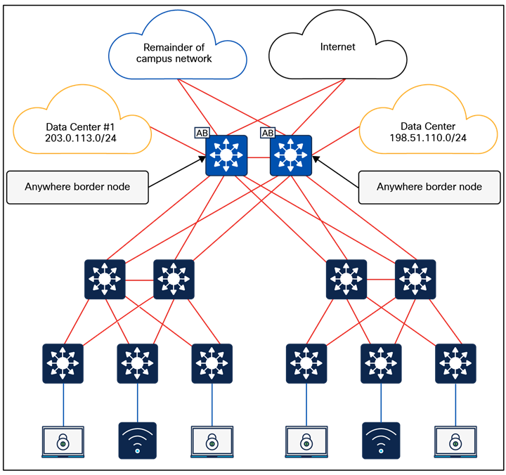
WLC guest anchor using a centrally switched guest SSID
In this case the guest SSID acts like a centralized wireless deployment. It can also be leveraged for those cases where a seamless roam across multiple fabric sites within the same campus is a requirement and the scale is beyond what multisite remote border (mentioned above) can satisfy.
Feature-specific design considerations
This section is organized into the following subsections:
| Section |
Subsection |
| Feature-specific design considerations |
Multicast is supported in both the overlay virtual networks and the physical underlay networks in SD-Access, with each achieving different purposes as discussed below.
The multicast source either can be outside the fabric site (commonly in the data center) or can be in the fabric overlay, directly connected to an edge node or extended node, or associated with a fabric access point. Multicast receivers are commonly directly connected to edge nodes or extended nodes, although they can also be outside of the fabric site.
PIM Any Source Multicast (PIM-ASM) and PIM Source-Specific Multicast (PIM-SSM) are supported in both the overlay and underlay. The overlay or the underlay can be used as the transport for multicast as described in the Multicast Forwarding in SD-Access section.
Multicast routing over LISP Pub/Sub SD-Access transit is supported, and multicast routing over LISP/BGP SD-Access transit is not supported.
Rendezvous point design
In a PIM-ASM routing architecture, the multicast distribution tree is rooted at the rendezvous point (RP). This is referred to as a shared tree or RP-tree (RPT), as the RP acts as the meeting point for sources and receivers of multicast data.
An RP can be active for multiple multicast groups, or multiple RPs can be deployed to each cover an individual group. The information regarding which RP is handling which group must be known by all the routers in the multicast domain. For this group-to-RP mapping to occur, multicast routing devices must be able to locate the RP in the network. In traditional multicast networks, this can be accomplished through static RPs, a bootstrap router (BSR), Auto-RP, or Anycast-RP.
Anycast-RP allows two or more RPs to share the load for multicast source registration and act as hot standbys for each other. Anycast-RP is the preferred method in SD-Access and is the method used during the PIM-ASM automation workflows.
When PIM-ASM is used in the overlay and multiple RPs are defined within the fabric site, Cisco Catalyst Center automates the Multicast Source Discovery Protocol (MSDP) configuration on the RPs and configures the other fabric nodes within a given fabric site to point to these RPs for a given virtual network.
Rendezvous point placement
PIM is used to build a path backward from the receiver to the source, effectively building a tree. This tree has a root with branches leading out to subscribers for a given stream. With PIM-ASM, the root of the tree is the RP. With PIM-SSM, the root of the multicast tree is the source itself.
Source tree models (PIM-SSM) have the advantage of creating the optimal path between the source and the receiver without the need to meet a centralized point (the RP). In a shared tree model (PIM-ASM), the path through the RP may not be the shortest path from receiver back to source. However, PIM-ASM does have an automatic method called switchover to help with this. Switchover moves from the shared tree, which has a path to the source by way of the RP, to a source tree, which has a path directly to the source. This capability provides an automatic path optimization capability for applications that use PIM-ASM.
In an environment with fixed multicast sources, RPs can easily be placed to provide the shortest-path tree. In environments with dynamic multicast sources, RPs are commonly placed in the core of a network. In traditional networking, network cores are designed to interconnect all modules of the network together, providing IP reachability, and generally have the resources, capabilities, and scale to support being deployed as an RP.
In SD-Access networks, border nodes act as convergence points between the fabric and nonfabric networks. Border nodes are effectively the core of the SD-Access network. As discussed above, border node device selection is based on a device having the resources, scale, and capability to support being the aggregation point between fabric and nonfabric.
Multicast sources are commonly located outside the fabric site, such as with music on hold, streaming video/video conferencing, and live audio paging and alert notifications. For unicast and multicast traffic, the border nodes must be traversed to reach destinations outside of the fabric. The border nodes already represent the shortest path.
Most environments can achieve a balance between optimal RP placement and the need for a device with appropriate resources and scale by selecting their border node as the location for their multicast RP.
When there is ASM routing between fabric sites over SD-Access transit, each Layer 3 virtual network must use the same RP per multicast group; for example:
● Fabric Site 1, 2, and 3, L3VN1 -> RP 1.1.1.1 for all multicast groups
● Fabric Site 1, 2, and 3, L3VN2 -> RP 2.2.2.2 for multicast group 224.2.2.0/24, and RP 3.3.3.3 for multicast group 224.3.3.0/24
External RP
Nonfabric external devices can be designated as RPs for a fabric site. The external RP address must be reachable in the virtual network routing table on the border nodes. External RP placement allows existing RPs in the network to be used with the fabric. In this way multicast can be enabled without the need for new MSDP connections. If RPs already exist in the nonfabric network, using these external RPs is often the preferred method to enable multicast.
Multicast forwarding in SD-Access
SD-Access supports two different transport methods for forwarding multicast. One uses the overlay and is referred to as head-end replication, and the other uses the underlay and is called native multicast. Multicast forwarding is enabled per virtual network. However, if native multicast is enabled for a VN, head-end replication cannot be used for another VN in the fabric site. These two options are mutually exclusive within the fabric site.
Head-end replication
Head-end replication (or ingress replication) is performed by the multicast first-hop router (FHR). If the multicast source is within the fabric, the FHR is an edge node. If the multicast source is outside the fabric, the FHR is a border node.
With head-end replication the multicast packets from the source are replicated and sent, via unicast, by the FHR to all last-hop routers (LHRs) with interested subscribers.
For example, consider a fabric site that has 26 edge nodes. Each edge node has receivers for a given multicast group, and the multicast source is connected to one of the edge nodes. The FHR edge node must replicate each multicast packet to the other 25 edge nodes. This replication is performed per source, and packets are sent across the overlay. A second source means another 25 unicast replications. If the border node acts as the FHR for the fabric site, it performs the head-end replication to all fabric devices with interested multicast subscribers.

SD-Access multicast head-end replication packet
The advantage of head-end replication is that it operates entirely in the overlay and does not require multicast in the underlay network. This mode makes it suitable for environments where underlay multicast cannot be enabled and creates a complete decoupling of the virtual and physical networks from a multicast perspective. However, if there are many LHRs, this can create high overhead on the FHRs, consuming additional CPU and bandwidth resources. Network designers should consider native multicast due to its efficiency and the reduction of load on the FHR fabric node. This mode does provide overlay IPv4 multicast support within fabric sites and optionally between fabric sites if there is a LISP Pub/Sub SD-Access transit.
Native multicast
Native multicast does not require the ingress fabric node to do unicast replication. Rather, the whole underlay, including intermediate nodes, is used to do the replication. To support native multicast, the FHRs, LHRs, and all network infrastructure between them must be enabled for multicast.
Native multicast requires multicast to be enabled in the underlay but significantly reduces the replication load on the FHR, making it the preferred choice from an efficiency and scalability standpoint. It uses PIM-SSM for the underlay multicast transport. The overlay multicast messages are tunneled inside underlay multicast messages. This behavior also allows overlap in the overlay and underlay multicast groups in the network, if needed.
Native multicast works by performing multicast-in-multicast encapsulation. Multicast packets from the overlay are encapsulated in multicast in the underlay. With this behavior, both PIM-SSM and PIM-ASM can be used in the overlay. A key limitation is that native multicast does not provide IPv6 multicast support within or across fabric sites.
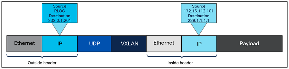
SD-Access native multicast packet
Layer 2 flooding is a feature that enables the flooding of broadcast, link-local multicast, and Address Resolution Protocol (ARP) traffic for a given overlay subnet. In traditional networking, broadcasts are flooded out of all ports in the same VLAN. By default, SD-Access transports frames without flooding Layer 2 broadcast and unknown unicast traffic, and other methods are used to address ARP requirements and ensure that standard IP communication gets from one endpoint to another.
However, some networks need to use broadcast, particularly to support silent hosts, which generally require reception of an ARP broadcast to come out of silence. Another common use case for broadcast frames is wake-on-LAN (WoL) Ethernet broadcasts, which occur when the source and destination are in the same subnet or when a subnet-directed broadcast originates from outside the fabric.
Because the default behavior, suppression of broadcast, allows for the use of larger IP address pools, the pool size of the overlay subnet needs careful consideration when Layer 2 flooding is enabled. Consider using a /24 (24-bit netmask) or smaller address pool to limit the number of broadcasts, as each of these frames must be processed by every device in the segment. Layer 2 flooding should be used selectively where needed, with a small address pool, and it is not enabled by default.
Layer 2 flooding works by mapping the overlay subnet to a dedicated multicast group in the underlay. Broadcast, link-local multicast, and ARP traffic are encapsulated in a fabric VXLAN and sent to the destination underlay multicast group. PIM-ASM is used as the transport mechanism.
When Layer 2 flooding is enabled for a given overlay segment, all edge nodes hosting the segment will send multicast PIM joins for the respective underlay multicast group, effectively prebuilding a multicast shared tree. A shared tree must be rooted at a rendezvous point, and for Layer 2 flooding to work, this RP must be in the underlay. The RP can be configured manually or programmatically through LAN Automation.
If LAN Automation is used, the LAN Automation primary device (seed device) along with its redundant peer (peer seed device) are configured as the underlay RPs on all discovered devices. MSDP is automated between the seeds to create the Anycast-RP configuration needed in the underlay for Layer 2 flooding. In addition, PIM sparse mode is enabled on Loopback 0 and all point-to-point interfaces configured through the LAN Automation process on the devices.
If Layer 2 flooding is needed and LAN Automation was not used to discover all the devices in the fabric site, underlay multicast routing needs to be enabled manually on the devices in the fabric site. MSDP should be configured between Anycast-RPs in the underlay. Loopback 0 can be used as the connect-source and originator-ID for the MSDP peering. Loopback 60000 can be used to host the Anycast-RP address on the MSDP peers.
The Apple Bonjour protocol allows devices and services to discover each other. It relies on mDNS which uses a link-local multicast group. mDNS may need to pass over VXLAN between fabric edge nodes, for example, a browsing client on EN1 and a service provider on EN2. mDNS can be forwarded over VXLAN by enabling SD-Access layer 2 flooding.
Precision Time Protocol (PTP), defined by IEEE 1588v2, provides a mechanism to synchronize clocks across networked devices with sub-microsecond accuracy. In SD-Access environments, PTP operates as a global service in the fabric underlay.
Quality of service in Cisco SD-Access
Quality of service (QoS) in Cisco SD-Access simplifies traffic prioritization by using a centralized policy approach managed through Cisco Catalyst Center. When devices connect to the fabric, edge node downlink ports provide classification and marking functions using Next-Generation Network-Based Application Recognition (NBAR2) deep packet inspection and honor incoming class of service (CoS)/DSCP marking at the trust boundary. For wireless traffic, the fabric access point serves as the QoS classification/marking point, based on SSID settings. These QoS markings are preserved as traffic moves through the fabric overlay using VXLAN encapsulation, ensuring that priority treatment remains consistent across all fabric nodes, whether wired or wireless. Tunneled packet QoS markings are copied to the VXLAN IP header for consistent end-to-end QoS. Queueing and scheduling functions are performed on all the uplinks starting from the edge node all the way up to the border nodes, splitting traffic into multiple queues for congestion management using built-in device-specific models.
This section is organized into the following subsections:
| Section |
Subsection |
| External connectivity |
External connectivity outside of the fabric site can have several possible variations, and these variations are based on underlying network design. For example, the fabric border node may be connected to an actual internet edge router, an ISP device, a firewall, a services block switch, or some other routing infrastructure device. Each of these peer devices may be configured with a VRF-aware connection (VRF-lite) or may simply connect to the border node using the global routing table.
Shared services, as discussed in the earlier Shared Services Design section, may be deployed in a dedicated VRF or the global routing table, and shared services may be connected to a services block or be accessed through data center infrastructure. Internet access itself may be in a VRF, though it is most commonly available in the global routing table. While each of these options are viable, each presents a different underlying network design that the fabric site must integrate with.
Regardless of the potential variations used in the network design and deployment outside of the fabric site, these designs have a few characteristics in common, and the border node will be the device tying these characteristics together:
● VRF-aware: A border node will be VRF-aware. All user-defined virtual networks in the fabric site are instantiated and provisioned as VRFs.
● Site prefixes in VRF: The EID-space prefixes associated with the fabric site will be in VRF routing tables on the border node.
● Upstream infrastructure: The border nodes will be connected to a next-hop device and further routing infrastructure (referenced simply as next hop, for brevity). This upstream infrastructure, while a necessary part of the overall design, is not part of the fabric site and is therefore not automated though SD-Access workflows in Cisco Catalyst Center.
Cisco Catalyst Center can automate the configuration on the border nodes; this is done through an IP-based Layer 3 handoff. IP-based means that native IP forwarding, rather than encapsulation, is used. The fabric packet is de-encapsulated before being forwarded. The configuration is Layer 3, which means it uses subinterfaces when the border node is a routing platform or SVIs when the border node is a switching platform to connect to the upstream peers.
This Layer 3 handoff automation provisions VRF-lite by associating each SVI or subinterface with a different fabric virtual network (VRF). External BGP is used as the routing protocol to advertise the endpoint space (EID-space) prefixes from the fabric site to the external routing domain and to attract traffic back to the EID-space. This BGP peering can also be used to advertise routes into the overlay such as for access to shared services.
While the Layer 3 handoff for external connectivity can be performed manually, automation through Catalyst Center is recommended.
With the Layer 3 IP-based handoff configured, there are several common configuration options for the next-hop device. This device may peer (have IP connectivity and routing adjacency) with the border node using VRFs. It may even continue the VRF segmentation extension to its next hop. This next-hop device may not be VRF-aware and may peer to the border node using the global routing table.
A VRF-aware peer design begins with VRF-lite automated on the border node through Cisco Catalyst Center and the peer manually configured as VRF-aware. For each virtual network that is handed off on the border node, a corresponding VRF and interface are configured on the peer device. Existing collateral may refer to this deployment option as a peer router or peer device.
The generic term peer router comes from MPLS Layer 3 VPN. The basic concept is that the peer router is aware of the prefixes available inside each VPN (VRF), generally through dynamic routing, and can therefore fuse these routes together. In MPLS Layer 3 VPN, these generic peer routers are used to route traffic between separate VRFs (VRF leaking). Alternatively, the peer router can be used to route traffic between a VRF and a shared pool of resources in the global routing table (route leaking). Both responsibilities are essentially the same, as they involve advertising routes from one routing table into a separate routing table.
This VRF-aware peer design is commonly used for access to shared services. Shared services are generally deployed using a services block on a switching platform to allow for redundant and highly available Layer 2 links to the various devices and servers hosting these services. Shared services most commonly exist in the global routing table, though deployments may use a dedicated VRF to simplify configuration.
In an SD-Access deployment, the peer device has a single responsibility: to provide access to shared services for the endpoints in the fabric. There are two primary ways to accomplish this task, depending on whether the shared services are deployed via route leaking or VRF leaking. Both require the peer device to be deployed as VRF-aware.
● Route leaking: This option is used when the shared services routes are in the global routing table. On the peer device, IP prefix lists are used to match the shared services routes, route maps reference the IP prefix lists, and the VRF configurations reference the route maps to ensure that only the specifically matched routes are leaked.
● VRF leaking: This option is used when shared services are deployed in a dedicated VRF on the peer device. Route targets under the VRF configuration are used to leak between the fabric virtual networks and the shared services VRF.
A peer device can be either a true routing platform, a Layer 3 switching platform, or a firewall, and must meet several technological requirements. It must support:
● Multiple VRFs: Multiple VRFs are needed for the VRF-aware peer model. For each virtual network that is handed off on the border node, a corresponding VRF and interface are configured on the peer device. The selected platform should support the number of VNs used in the fabric site that will require access to shared services.
● Subinterfaces (routers or firewall): A subinterface is a virtual Layer 3 interface that is associated with a VLAN ID on a routed physical interface. It extends IP routing capabilities to support VLAN configurations using IEEE 802.1Q encapsulation.
● Switched virtual interfaces (Layer 3 switch): An SVI represents a logical Layer 3 interface on a switch. It is a Layer 3 interface forwarding for a Layer 3 IEEE 802.1Q VLAN.
● IEEE 802.1Q: This internal tagging mechanism inserts a 4-byte tag field in the original Ethernet frame between the Source Address and Type/Length fields. Devices that support SVIs and subinterfaces will also support 802.1Q tagging.
● BGP-4: This is the current version of BGP and was defined in RFC 4271 (2006) with additional update RFCs. Along with BGP-4, the device should also support the multiprotocol BGP extensions such as Address Family Identifier (AFI), Subsequent AFI (SAFI), and extended community attributes defined in RFC 4760 (2007).
To support this route-leaking responsibility, the device should be properly sized according to the number of VRFs, bandwidth and throughput requirements, and Layer 1 connectivity needs, including port density and type. When the network has been designed with a services block, the services block switch can be used as the peer device (VRF-aware peer) if it supports the criteria described above. Peer devices should be deployed in pairs or as a multibox, a single logical box such as StackWise Virtual, or a vPC. When the peer device is a logical unit, border nodes should be connected to both members of the logical pair.
This deployment type begins with VRF-lite automated on the border node and the peer manually configured, though not VRF-aware. For each virtual network that is handed off on the border node, a corresponding interface is configured on the peer device in the global routing table. This deployment option is commonly used when the fabric site hands off to a WAN circuit, an ISP, an MPLS customer edge (CE) or provider edge (PE) device, another upstream routing infrastructure, or even a firewall, which is a special-case non-VRF peer, as discussed further in the Firewall Peer section.
This deployment type is common in WAN infrastructure. If this next-hop peer is an MPLS CE, routes are often merged into a single table to reduce the number of VRFs to be carried across the backbone, generally reducing overall operational costs. If the next-hop peer is MPLS PE or ISP equipment, it is outside of the administrative domain of the fabric network operator. The result is that there is little flexibility in controlling the configuration on the upstream infrastructure. Many times, ISPs have their own peering strategies and are themselves presenting a Layer 3 handoff to connected devices.
Non-VRF-aware means that the peer router is not performing VRF-lite. It may have the functionality to support VRFs, but it is not configured with corresponding fabric VRFs the way a VRF-aware peer would be. The non-VRF-aware peer is commonly used to advertise a default route to the endpoint space in the fabric site.
The result is that the virtual networks from the fabric site are merged into a single global routing table on the next-hop peer. Merging routes into a single table is a different process than route leaking. This deployment type does use the colloquial moniker of peer router.
The challenge with merged tables is the potential for east-west communication to occur across the north-south link. Merging the VRFs into a common routing table is best accomplished with a firewall. Firewalls are policy-oriented devices that align well with the segmentation provided through the SD-Access solution.
It is not always possible to use a firewall in environments that use route-table merging, as is the case with the WAN circuits listed above. However, degrees of precaution and security can be maintained, even without a firewall. For example, specific SGTs or port-based ACLs can limit and prevent east-west communication. Further protection can be added by sinkhole routing. This is done manually on the border node for each VRF by pointing the aggregate prefixes for every other VRF to Null0.
In the simplified topology in Figure 25 below, the border node is connected to a non-VRF-aware peer, with each fabric virtual network and its associated subnet represented by a color. This type of connection effectively merges the fabric VN routing tables into a single table (generally the global routing table) on the peer device. Route sinking, as described above, can prevent east-west communication between the VNs across the north-south link between the border node and its peer.
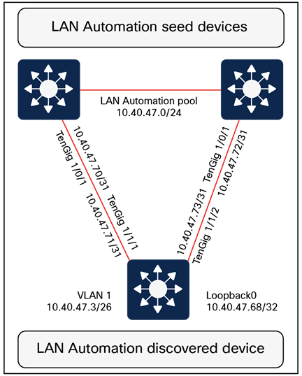
Simplified route sinking example
Layer 3 handoff using extranet
● The extranet feature was introduced starting with Cisco Catalyst Center Release 2.3.5.x. This feature uses a policy-based approach to VRF leaking, effectively preventing route leaking outside the fabric site by handling it directly within LISP. LISP Extranet offers a flexible and scalable solution for providing endpoints inside the fabric with access to shared services and the internet. It is useful for providing access to shared services and the internet from multiple subscriber VNs. When using extranet Layer 3 handoff, it should be applied only for the provider virtual network. Provider-to-provider and subscriber-to-subscriber communication policies are not supported. Communication is allowed only from subscriber VNs to the provider VN.
The extranet architecture consists of:
● Provider virtual network: Hosts’ shared services such as DHCP, DNS, or even internet access.
● Subscriber virtual network: Contains endpoints, hosts, and users needing access to shared services.
● Extranet policy: Defines the relationship between a provider virtual network and one or more subscriber virtual networks.
● Extranet policy orchestration: Extranet policies are created and maintained via Catalyst Center. These policies can be associated with one or more fabric sites connected via IP transit or SD-Access transit.
● Each extranet policy instance allows one provider VN and multiple subscriber VNs.
| Tech tip |
| Multicast routing between provider VNs and subscriber VNs is not supported. |
If the fabric virtual networks need to merge into a common routing table, a policy-oriented device such as a firewall should be considered as an upstream peer from the fabric border nodes. Common use cases for a firewall peer include internet access, access to data center prefixes, WAN connectivity, or inter-VN communication requirements.
A firewall can be used to provide stateful inspection for inter-VN communication, along with providing intrusion prevention system (IPS) capabilities, Advanced Malware Protection (AMP), granular AVC, and even URL filtering. Firewalls such as Cisco Secure Firewall also provide a very rich reporting capability, with information on traffic source, destination, username, group, and firewall action with guaranteed logging of permits and drops.
Firewalls can be deployed as a cluster (multiple devices acting as a single logical unit), as an HA pair (commonly active/standby), or even as a standalone device. While firewalls do not generally have VRF capabilities, they have other methods for providing the same general type of segmentation provided by VRFs. These can include contexts, interface-specific ACLs and security levels, instances, and security zones.
Additional firewall design considerations
When planning to use a firewall as the peer device, there are additional considerations. The device must be appropriately licensed and sized for throughput at a particular average packet size that takes into account the enabled features (IPS, AMP, AVC, URL filtering) and connections per second. It must also have the appropriate interface type and quantity to support connectivity to both its upstream and downstream peers and to itself when deploying a firewall cluster or firewall HA pair.
Layer 2 border handoff provides a Layer 2 connection between the SD-Access fabric and a nonfabric network, allowing hosts in both to communicate at Layer 2. Layer 2 handoff can connect either routed SD-Access segments (segments with an SVI anycast gateway) or Layer 2 VNs (no SVI anycast gateway) to traditional nonfabric VLANs.
The Layer 2 border handoff allows the fabric site and the traditional network VLAN to operate using the same subnet and switching domain. Communication between the two is provided across the border node with this handoff that provides a VLAN translation or a VLAN extension between fabric and nonfabric.
Cisco Catalyst Center automates the LISP control plane configuration along with the VLAN translation and the trunk port connected to the traditional network on this border node.
For routed SD-Access segments, the anycast gateway SVI is provisioned to the Layer 2 handoff and the border node configured with the Layer 2 handoff becomes the default gateway for the VLAN in the traditional network. Any SVI with the same IP address present in the traditional network must be disabled. Multicast is supported across the Layer 2 handoff, allowing multicast communication between the traditional network and the SD-Access network. The multicast forwarding logic operates the same across the Layer 2 handoff border node as it does in the fabric, as described in the Multicast Forwarding in SD-Access section, and the traditional network will flood multicast packets using common Layer 2 operations.
For SD-Access Layer 2 VNs, the fabric Layer 2 switching domain is bridged over the Layer 2 handoff toward the traditional network. Figure 26 shows how Layer 2 handoff implements handoff of routed segments and Layer 2 VNs.
An alternative design is to connect a Layer 2 external domain to the fabric edge node as well.
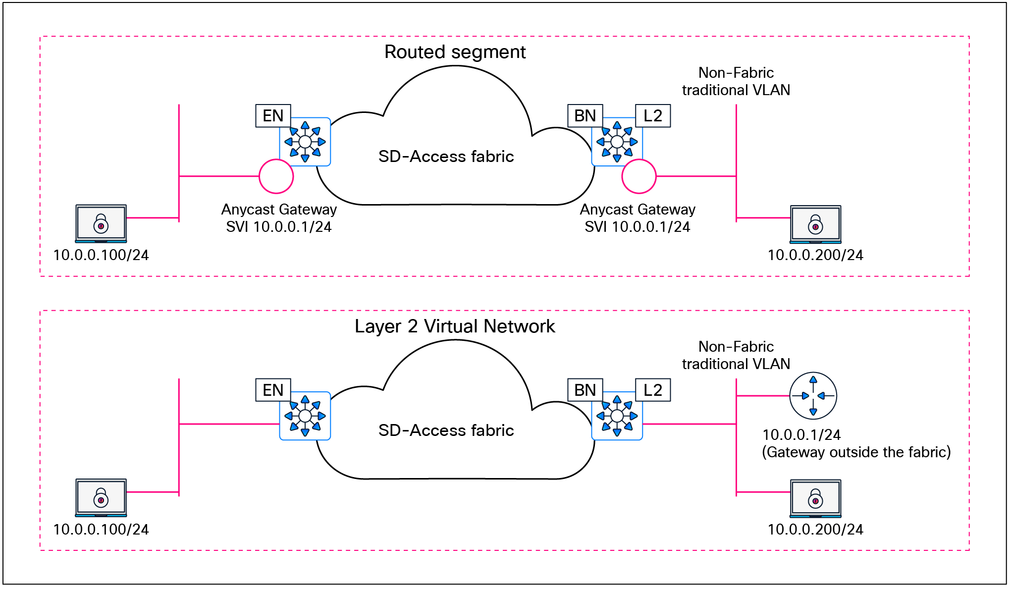
Layer 2 border handoff logical topologies
Deployment models and topology
The nonfabric network can be connected to a single border node with a Layer 2 handoff. The nonfabric network traditional switches should not be connected to multiple border nodes. Dual homing, however, is supported using link aggregation. MEC is supported to a single border node if the traditional switches are operating as a single logical switch, such as a hardware switch stack or StackWise Virtual. Redundancy for the border node itself can be provided through hardware stacking or StackWise Virtual.

Layer 2 border handoff physical topologies
Design considerations
Devices operating with an edge node role, including Fabric in a Box, are not supported with Layer 2 border handoff. The border node with the Layer 2 handoff should be a dedicated role. While it is technically feasible for this device to operate in multiple roles (such as a border node with Layer 3 handoff and a control plane node), it is recommended that a dedicated device be used. Because this device is operating at Layer 2, it is subject to the spanning-tree design impacts and constraints of the brownfield traditional network, and a potential storm or loop in the traditional network could impact the Layer 2 handoff border node. Dedicating this border node to the function of connecting to the traditional network separates the impact away from the remainder of the fabric network, which can continue to operate independently of the traditional network. The device must be operating in transparent mode for VLAN Trunking Protocol (VTP) to avoid unintended modification of the traditional network’s VLANs. The allowed VLAN range for traditional networks is 2 to 4094, excluding reserved VLANs 1, 1002 to 1005, 2046, and 4094.
This section is organized into the following subsections:
| Section |
Subsection |
| Security considerations |
Authentication template options
The primary intent behind authentication templates in SD‑Access fabric deployments is to ensure that users and devices authenticate against Cisco ISE, allowing ISE to dynamically apply the appropriate network access authorization (for example, VN/IP pool selection via dynamic VLAN and TrustSec SGT assignment) as endpoints join the fabric. As in traditional networks, users and devices in an SD‑Access fabric can authenticate using IEEE 802.1X, MAC Authentication Bypass (MAB) or web authentication. Of these options, IEEE 802.1X provides the strongest level of access control and is therefore the recommended primary method for fabric access authentication, with MAB and web authentication reserved for legacy and exception use cases. By default, IEEE 802.1X is attempted first, with MAB used as a fallback after a configurable 802.1X timeout. In environments with a high number of IoT clients that lack 802.1X supplicants, SD-Access allows the option of reversing this order so that MAB is used as the primary method with 802.1X as the fallback.
SD-Access leverages IBNS 2.0 style on all fabric edge switches so that all access ports enforce consistent identity‑based access, which is then mapped into virtual networks and SGT‑based policies in the fabric onboarding intent. Similar to traditional networks, SD‑Access uses three IBNS deployment modes that map to how strictly identity is enforced at the fabric edge. These modes roughly align with closed (full enforcement), low‑impact or staged (partial enforcement while you migrate), and open/monitor (no enforcement, visibility only). Cisco Catalyst Center provides a flexible UI for host onboarding, allowing operators to move specific ports in the deployment between open/monitor, low‑impact, and closed 802.1X modes by simply changing the authentication template for the entire fabric site rather than reconfiguring individual switch ports.
For brownfield environments, enabling 802.1X enforcement on day 1 can be disruptive, so a phased deployment is recommended: Start in open/monitor mode to gain visibility and validate authentications without blocking traffic, then progressively move segments to low‑impact and finally closed mode as devices, supplicants, and policies are verified. For greenfield environments with all infrastructure and identity services in place, the recommendation is to start with closed mode for all user and device access ports, bringing the deployment a step closer to a zero‑trust architecture from day 1.
MACsec is a Layer 2 encryption standard that protects traffic across untrusted or high‑risk physical links. There is currently no dedicated Catalyst Center workflow to enable MACsec from switch to switch, so day‑N templates must be used to configure MACsec on the required interfaces. With Catalyst Center Release 2.3.7.x and Cisco IOS XE Release 17.x, a single interface does not support concurrent MACsec and Cisco TrustSec inline tagging; for example, MACsec cannot be enabled on links between fabric edge and PEN or SBEN devices when TrustSec inline tagging is used. Refer to the product-specific documentation and platform capability matrices for detailed and up‑to‑date restrictions on MACsec and TrustSec inline tagging support for each hardware platform. As of Catalyst Center Release 2.3.7.x, switch-to-host MACsec is not supported in SD-Access fabric deployments.
By default, when a network access device (NAD) cannot reach its configured RADIUS servers, new hosts connected to the NAD cannot be authenticated and are not provided access to the network. The inaccessible authentication bypass feature, also referred to as critical authentication, AAA fail policy, or simply critical VLAN, allows network access on a particular VLAN when the RADIUS server is not available (down).
When a NAD tries to authenticate an endpoint connected to a port, it first checks the status of the configured RADIUS servers. If a server is available, the NAD can authenticate the host. If all the configured RADIUS servers are unavailable and the critical VLAN feature is enabled, the NAD grants network access to the endpoint and puts the port in the critical-authentication state, which is a special-case authentication state. When the RADIUS servers are available again, clients in the critical-authentication state must reauthenticate to the network.
Similarly, critical voice VLAN support works by putting voice traffic into the configured voice VLAN if the RADIUS server becomes unreachable.
Critical VLAN design considerations
Within a fabric site, a single subnet can be assigned to the critical data VLAN. The critical voice VLAN does not need to be explicitly defined, as the same VLAN is used for both voice and critical voice VLAN support. This ensures that phones will have network access whether the RADIUS server is available or not. SD-Access uses VLAN 2046 and VLAN 2047 for the critical voice VLAN and critical (data) VLAN, respectively.
As discussed in the Fabric Overlay Design section, SD-Access creates segmentation in the network using two method: VRFs (virtual networks) for macro-segmentation and SGTs (group-based access control) for micro-segmentation. By default, users, devices, and applications in the same VN can communicate with each other. SGTs can permit or deny this communication within a given VN.
When designing the network for the critical VLAN, this default macro-segmentation behavior must be considered. For example, suppose that the subnet assigned for development servers is also defined as the critical VLAN. In the event of the RADIUS server being unavailable, new devices connecting to the network will be placed in the same VLAN as the development servers. Because these devices are in the same VN, communication can occur between them. This is potentially highly undesirable.
Creating a dedicated VN with limited network access for the critical VLAN is the recommended and most secure approach. In the event of RADIUS unavailability, new devices connecting to the network will be placed in their own VN, which automatically segments their traffic from any other, previously authenticated hosts.
The dedicated critical VN approach must look at the lowest common denominator with respect to the total number of VNs supported by a fabric device. Certain switch models support only one or four user-defined VNs. Using a dedicated VN for the critical VLAN may exceed this scale, depending on the total number of other user-defined VNs at the fabric site and the platforms used.
If there is a requirement to use more than one critical data VLAN per site, or to reuse existing user VLANs as critical VLANs, the recommendation is to configure those user ports with the appropriate static VLANs while enabling the Closed authentication template. When Cisco ISE is unreachable, IBNS 2.0 behavior causes the switch to authorize the port locally and fall back to the statically configured VLAN on that port, effectively using it as the critical VLAN.
| Tech tip |
| Please see the Cisco Catalyst Center data sheet for device-specific fabric VN scale. |
Multidimensional considerations
This section is organized into the following subsections:
| Section |
Subsection |
| Multidimensional considerations |
An SD-Access network begins with a foundation of the Cisco Enterprise Architecture Model with well-designed and planned hierarchical network structures that include modular and extensible network. On this foundation, the network is designing and configured using the Layer 3 routed access model.
While individual sites can have some design and configuration that is independent from other locations, this design and configuration must consider how the site becomes part of the larger campus network, including other fabric sites, nonfabric sites, shared services, data center, WAN, and internet. No element, consideration, or fabric site should be viewed in isolation, and an end-to-end view of the network must be taken into account.
The design strategy for SD-Access is to maximize site size while minimizing site count. Each of the factors below could drive the need to deploy multiple smaller fabric sites rather than one larger one.
Greenfield (new) networks have the advantage that the network can be designed as new from the ground up. Brownfield (existing) networks may have less flexibility due to geography, fiber, or existing configurations. Ultimately, the goal in a brownfield environment is to use it in an SD-Access network, and careful and accurate information, configuration, and topology details for the existing network should be collected in advance of migration. Migration from a traditional network to an SD-Access network can be accomplished through the following approaches:
● Layer 2 handoff: This approach connects a traditional network with an SD-Access network. It can be used during transitions and migrations in concert with the building-by-building approach.
● Building by building: Areas of the existing network are converted to SD-Access. This is commonly done closet by closet (IDF by IDF) or building by building. Migration is done, at minimum, one switch at a time. One VLAN at a time is not supported, as the VLAN may span multiple traditional switches.
| Tech tip |
| Layer 2 border handoff considerations are discussed further in the Migration to SD-Access section. |
The most significant factor in the selection of equipment and topology for a site, apart from existing wiring, is the total number of wired and wireless clients in that location. This will determine the number of physical switch ports and access points required, which will determine the need for three-tier or two-tier network designs. The number of clients may be small enough that the network is composed of a switch stack or large enough to cover multiple buildings with many thousands of endpoints.
The number of fabric devices in a site is a count of all of the routers, switches, classic and policy extended nodes, and wireless controllers that are operating in a fabric role. Cisco Catalyst Center can support a specific number of network devices in total and a maximum number per fabric site. Each of these scale numbers varies based on the appliance size, and they may also vary by release. The maximum number of devices may be a reason to create several smaller fabric sites rather than one very large site. Please consult the Cisco Catalyst Center Appliance Scale and Hardware Specifications on the Catalyst Center data sheet for the specific maximum number of fabric devices per site for the current release.
Physical geography impacts the network design. It may not have a direct impact on the topology within the fabric site itself, but geography must be considered as it relates to transit types, service locations, survivability, and high availability.
Locations that are situated within the same MAN or campus with multiple buildings in close physical proximity with interconnecting direct fiber can benefit from an SD-Access for Distributed Campus design. A distributed campus deployment, by extension, allows for native, unified policy across the locations as well as the potential to have a single services block location.
Locations connected across WAN or internet circuits, where the fabric packet is de-encapsulated as it leaves the fabric, must consider shared services location, methods to maintain unified policy constructs across the circuits, and the routing infrastructure that exists outside of the fabric.
Services such as DHCP, DNS, ISE, and WLCs are required elements for clients in an SD-Access network. Services are commonly deployed in one of three ways.
● Fabric-site local: For survivability purposes, a services block may be established at each fabric site location. Local services ensure that these critical services are not sent across the WAN/MAN/internet and ensure that the endpoints are able to access them in the event of congestion or unavailability of the external circuit. However, this may drive the need for VRF-aware peering devices to fuse routes from the fabric overlay to shared services.
● Centralized within the deployment: In locations distributed across a WAN, and in SD-Access for Distributed Campus deployments, services are often deployed at on-premises data centers. These data centers are commonly connected to the core or distribution layers of a centralized location such as a headquarters site. Traffic is sent from the remote and branch sites back to the central location and then directed toward the necessary services.
● Both centralized and fabric-site local: This is a hybrid of the two approaches above. For most fabric sites, services are centralized. Specific fabric sites with a need for services connectivity independent of the status of the WAN circuit use local services.
While not a specific factor in the decision to deploy multiple fabric sites, shared services must be considered as part of the deployment. A VRF-aware peer (peer device) is the most common deployment method to provide access to shared services, or the extranet capability could be used. For fabric sites needing resiliency, high availability, and site survivability independent of WAN status, local shared services are needed. These locations should plan for the use of a services block and VRF-aware peer to provide the fabric endpoint access to these services.
External internet and WAN connectivity for a fabric site has a significant number of possible variations. The key design consideration is to ensure that the routing infrastructure has the physical connectivity, routing information, scale, performance, and throughput necessary to connect the fabric sites to the external world.
Unified policy is a primary driver for the SD-Access solution. With unified policy, access control for wired and wireless traffic is consistently and uniformly enforced at the access layer (fabric edge node). Users, devices, and applications are subject to the same policy wherever and however they are connected in the network.
Within a fabric site, unified policy is both enabled and carried through the segment ID (group policy ID) and VXLAN network identifier (VNI) fields of the VXLAN-GPO header. This allows for both VRF (macro) and SGT (micro) segmentation information to be carried within the fabric site.
| Tech tip |
| Low-level details on the fabric VXLAN header can be found in Appendix A. |
With SD-Access transit, the same encapsulation method used for data packets within the fabric site is used for data packets between sites. This allows unified policy information to be natively carried in the data packets traversing between fabric sites in the larger fabric domain.
When designing for a multisite fabric that uses an IP-based transit between sites, consider whether a unified policy is desired between the disparate locations. Using an IP-based transit, the fabric packet is de-encapsulated into native IP. This results in a loss of embedded policy information. Carrying the VRF and SGT constructs without using a fabric VXLAN or, more accurately, once the VXLAN is de-encapsulated, is possible through other technologies, though.
End-to-end macro-segmentation (VRFs)
Segmentation beyond the fabric site has multiple variations, depending on the type of transit. SD-Access transit carries the VRF natively. In IP-based transits, due to de-encapsulation of the fabric packet, virtual network policy information can be lost. Several approaches exist to carry VN (VRF) information between fabric sites using an IP-based transit. The most straightforward approach is to configure VRF-lite hop by hop between fabric sites. While this is the simplest method, it also has the highest degree of administrative overhead. This method is not commonly used, as the IP-based infrastructure between fabric sites is generally under the administrative control of a service provider.
If VRF-lite cannot be used end to end, options still exist to carry VRFs. The VRF is associated with an 802.1Q VLAN to maintain the segmentation construct. The border node can be a routing or switching platform. However, the peer device may need to be a routing platform to support the applicable protocols. The handoff on the border node can be automated through Cisco Catalyst Center, though the peer router is configured manually or by using templates.
● Border node with SD-WAN peer: A VRF is handed off via a VLAN to an SD-WAN edge device subinterface. One SD-WAN VPN is usually configured per SD-Access VN.
● Border node with GRE peer: A VRF is handed off via a VLAN to a Generic Routing Encapsulation (GRE) tunnel endpoint router. On the tunnel endpoint router, one GRE tunnel is configured per fabric VN.
● Border node with DMVPN peer: A VRF is handed off via a VLAN to a Dynamic Multipoint VPN (DMVPN) router. On the DMVPN router, one DMVPN cloud is configured per fabric VN.
● Border node with IPsec peer: A VRF is handed off via a VLAN to an IPsec router. On the IPsec router, one IPsec tunnel is configured per fabric VN.
| Tech tip |
| For additional details, please see Cisco SD-Access Migration Tools and Strategies (BRKENS-2827). |
End-to-end micro-segmentation (SGTs)
Like VRFs, segmentation beyond the fabric site has multiple variations depending on the type of transit. SD-Access transit carries the SGT natively. In IP-based transit, due to the de-encapsulation of the fabric packet, SGT policy information can be lost. Two approaches exist to carry SGT information between fabric sites using an IP-based transit: inline tagging and SGT Exchange Protocol (SXP).
Inline tagging
Inline tagging is the process by which the SGT is carried within a special field known as CMD that can be inserted in the header of the Ethernet frame. This changes the EtherType of the frame to 0x8909. If the next-hop device does not understand this EtherType, the frame is assumed to be malformed and is discarded. Inline tagging can propagate SGTs end to end in two different ways:
● Hop by hop: Each device in the end-to-end chain will need to support inline tagging and propagate the SGT.
● Preserved in tunnels: SGTs can be preserved in CMD inside of GRE encapsulation or in CMD inside of IPsec encapsulation.
SGT Exchange Protocol over TCP
A second design option is to use SXP to carry the IP-to-SGT bindings between sites. SXP is used to carry SGTs across network devices that do not have support for inline tagging or if the tunnel used is not capable of carrying the tag.
SXP has both scaling and enforcement location implications that must be considered. Between fabric sites, SXP can be used to enforce the SGTs at either the border nodes or the routing infrastructure northbound of the border. If enforcement is done at the routing infrastructure, CMD is used to carry the SGT information inline from the border node.
If enforcement is done on the border node, a per-VRF SXP peering must be made with each border node to ISE. A common way to scale SXP more efficiently is to use SXP domains. A second alternative is to peer the border node with a non-VRF-aware peer and merge the routing tables. ISE then makes a single SXP connection to each of these peers.
More recently, SXPv5 has been introduced, with the goal of having just one SXP connection from ISE to borders and sending mappings for every VRF. Currently, without ISE supporting SXPv5, we need to deploy an SXP reflector for this use case in order to take advantage of the SXPv5 savings.
| Tech tip |
| For additional details on deployment scenarios, SGTs over GRE and VPN circuits, and scale information, please see the SD-Access Segmentation Design Guide. |
In the event that the WAN and MAN connections are unavailable, any services accessed across these circuits are unavailable to the endpoints in the fabric. The need for site survivability is determined by balancing the associated costs of the additional equipment and the business drivers behind the deployment while also factoring in the number of impacted users at a given site. Designing an SD-Access network for complete site survivability involves ensuring that shared services are local to every single fabric site. Generally, a balance between centralized and site-local services is used. If the business requires that a given fabric site always be available, it should have site-local services. Other fabric sites without the requirement can use centralized services.
High availability complements site survivability. A site with a single fabric border node, control plane node, or wireless controller risks single failure points in the event of a device outage. When designing for high availability in an SD-Access network, it is important to understand that redundant devices do not increase the overall scale. Redundant control plane nodes and redundant border nodes operate in an active/active configuration, and fabric WLCs operate as active/standby pairs.
SD-Access site reference models
This chapter is organized into the following sections:
| Chapter |
Section |
| SD-Access site reference models |
Fabric site sizes – Design strategy |
A Cisco SD-Access fabric site has the flexibility to fit many environments, which means it is not a one-design-fits-all proposition. The scale of a fabric can vary significantly from site to site.
Fabric site sizes – Design strategy
A practical goal for SD-Access designs is to create larger fabric sites rather than multiple smaller fabric sites. The design strategy is to maximize fabric site size while minimizing total site count. Some business requirements will necessitate splitting locations into multiple sites, such as creating a fabric site for an emergency room that is separate from the fabric site that represents the remainder of the hospital. The multidimensional factors of survivability, high availability, number of endpoints, services, and geography may all drive the need for multiple smaller fabric sites instead of a single large site. To help aid in the design of fabric sites of varying sizes, the reference models below were created.
In deployments with physical locations, you will use a different template for each of the different site types, such as a large branch, a regional hub, a headquarters, or a small remote office. The underlying design challenge is to look at the existing network and propose a method to layer SD-Access fabric sites in these areas. This process can be simplified and streamlined by templatizing designs into reference models. The templates drive understanding of common site designs by offering reference categories based on the multidimensional design elements along with the endpoint count to provide guidelines for designing sites of similar sizes. The numbers that follow are used as general guidelines only and do not necessarily match maximum scale and performance limits for devices within a reference design.
● Fabric in a Box site: Uses Fabric in a Box to cover a single fabric site, with resilience supported by switch stacking or StackWise Virtual; designed for fewer than 1000 endpoints and fewer than 50 APs; the border, control plane, edge, and wireless functions are colocated on a single redundant switching platform.
● Small site: Covers a single office or building; designed to support fewer than 10,000 endpoints and fewer than 500 APs; the border is colocated with the control plane function on one or two devices, and a separate wireless controller has an optional HA configuration.
● Medium site: Covers a building with multiple wiring closets or multiple buildings; designed to support fewer than 50,000 endpoints and fewer than 2500 APs; the border and control plane can be colocated on the same device or provisioned to separate devices, and a separate wireless controller has an HA configuration.
● Large site: Covers a large building with multiple wiring closets or multiple buildings; designed to support up to 100,000 endpoints and up to 10,000 APs; borders are distributed from the control plane function on redundant devices, and there are multiple separate wireless controllers in HA configurations.
Each fabric site includes a supporting set of control plane nodes, edge nodes, border nodes, and WLCs, sized appropriately from the listed categories. ISE Policy Service nodes are also distributed across the sites to meet survivability requirements.
| The Cisco Catalyst Center data sheet lists the scale capabilities of the various networking infrastructure devices that can be deployed into an SD-Access fabric site. A fabric site can support a maximum of four external border nodes. There is no limit on internal border nodes, other than the maximum number of fabric devices per site as listed in the Catalyst Center data sheet. However, we generally recommend that you design for the minimum necessary number of border nodes in a given fabric site to maintain administrative and routing simplicity. A fabric site with SD-Access Wireless can support a maximum of two control plane nodes for nonguest (enterprise) traffic, as discussed in the Wireless Design section. |
Fabric in a Box site reference model
The Fabric in a Box site reference model usually targets fewer than 1000 endpoints. The central component of this design is a switch stack or StackWise Virtual operating in all three fabric roles: control plane node, border node, and edge node. For a switch stack Fabric in a Box deployment, SD-Access Embedded Wireless is usually used to provide site-local WLC functionality. The site may contain an ISE Policy Service node, depending on the WAN/internet circuit and latency.
Use the table below to understand the guidelines to stay within for similar site sizes. The numbers are used as guidelines only and do not necessarily match specific limits for devices used in a design of this site size.
Table 1. Fabric in a Box site guideline (limits may be different)
| Endpoints, target fewer than |
1000 |
| Control plane nodes |
1 |
| External border nodes |
1 |
| Access points, target fewer than |
50 |
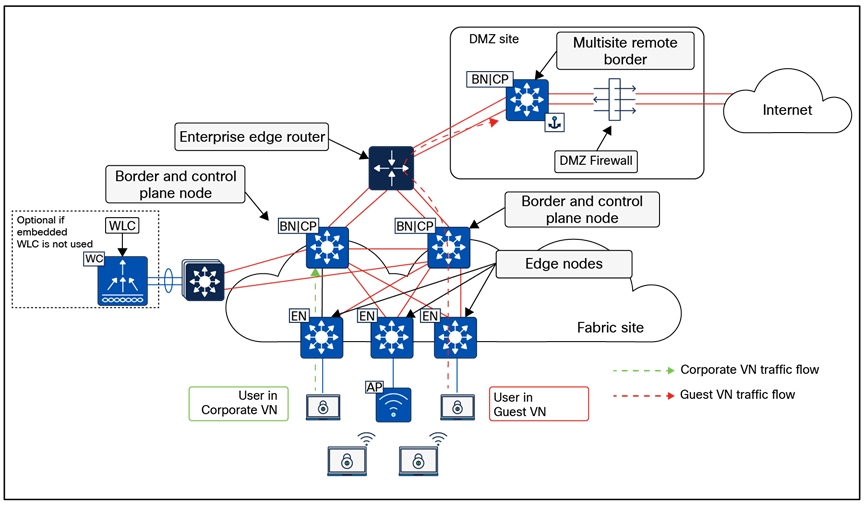
Physical topology – Fabric in a Box site design
Fabric in a Box site considerations
Due to the smaller number of endpoints, and thus the implied lower impact, high availability and site survivability are not common requirements for a Fabric in a Box design. As with all the reference designs, site-local services of DHCP, DNS, WLCs, and ISE can provide resiliency and survivability, although at the expense of increased complexity and equipment such as a services block.
High availability in this design is provided through StackWise-480 or StackWise Virtual, which both combine multiple physical switches into a single logical switch. If a chassis-based switch is used, high availability is provided through redundant supervisors and redundant power supplies.
WLCs can be deployed as physical units connected directly to the Fabric in a Box or deployed as the Catalyst 9800 Series embedded controller. When using the Catalyst 9800 Series EWC with a switch stack or redundant supervisor, AP and client Stateful Switchover (SSO) is provided automatically.
The small site reference model covers a building with multiple wiring closets or multiple buildings and typically has fewer than 10,000 endpoints. The physical network is usually a two-tier collapsed core/distribution with an access layer.
Use the table below to understand the guidelines to stay within for similar site sizes. The numbers are used as guidelines only and do not necessarily match specific limits for devices used in a design of this site size.
Table 2. Small site guidelines (limits may be different)
| Endpoints, target fewer than |
10,000 |
| Fabric nodes, target fewer than |
100 |
| Control plane nodes |
2 |
| External border nodes |
2 |
| Access points, target fewer than |
500 |
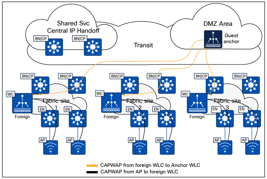
Physical topology – Small site reference design
Small site considerations
For smaller deployments, an SD-Access fabric site is often implemented using a two-tier design. In a small site, high availability is provided in the fabric nodes by colocating the border node and control plane node functionality on the collapsed core switches and deploying these as a pair. For both resiliency and alternative forwarding paths in the overlay and underlay, the collapsed core switches should be connected directly to each other with a crosslink.
The client and access point count calls for the use of dedicated WLCs. To enable highly available links for the WLC through physical connectivity, a services block is deployed. The WLCs are connected to the services block switch through Layer 2 port channels to provide redundant interfaces. The services block is a switch stack or StackWise Virtual that is connected to both collapsed core switches through Layer 3 routed links. This services block may be deployed as a VRF-aware peer if DHCP/DNS and other shared services are site-local.
The medium site reference model covers a building with multiple wiring closets or multiple buildings and is designed to support fewer than 50,000 endpoints. The physical network is usually a three-tier network with core, distribution, and access layers. The border and control plane node functionality can be colocated or provisioned to separate devices.
Use the table below to understand the guidelines to stay within for similar site sizes. The numbers are used as guidelines only and do not necessarily match specific limits for devices used in a design of this site size. The target maximum endpoint count requires, at minimum, the large Cisco Catalyst Center appliance and may require the extra-large Catalyst Center appliance.
Table 3. Medium site guidelines (limits may be different)
| Endpoints, target fewer than |
50,000 |
| Fabric nodes, target fewer than |
500 |
| Control plane nodes |
2 to 6 |
| External border nodes |
2 |
| Access points, target fewer than |
2500 |
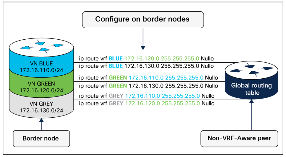
Physical topology – Medium site reference design
Medium site considerations
In a medium site, for both resiliency and alternative forwarding paths in the overlay and underlay, all devices within a given layer, with the exception of the access layer, should be crosslinked to each other. Multiple distribution blocks do not need to be cross-connected to each block, though they should cross-connect to all distribution switches within a block. If there are dedicated control plane nodes, they are generally connected to the core switches so that they are highly available for any edge node within the various distribution blocks. For optimal forwarding and redundancy, they should have connectivity through both cores and, if interfaces and fiber are available, should crosslink to each other, though this is not a requirement.
Physical WLCs should be deployed to support the wireless user scale. To enable high availability, a WLC HA-SSO pair is deployed with redundant physical connectivity to a services block using Layer 2 port channels. The services block is commonly implemented with fixed configuration switches operating as StackWise Virtual and connected to the core through Layer 3 routed links. This services block may be deployed as a VRF-aware peer if DHCP/DNS and other shared services are site-local.
The large site reference model covers a building with multiple wiring closets or multiple buildings. The physical network is often a three-tier network with core, distribution, and access and is designed to support up to 100,000 endpoints.
Use the table below to understand the guidelines to stay within for similar site sizes. The numbers are used as guidelines only and do not necessarily match specific limits for devices used in a design of this site size. The target maximum endpoint count requires, at minimum, the extra-large Cisco Catalyst Center appliance and may require a three-node cluster of extra-large Catalyst Center appliances. The Catalyst Center data sheet lists scale capabilities of the various networking infrastructure devices that can be used to implement an SD-Access fabric site.
Table 4. Large site guidelines (limits may be different)
| Endpoints, target fewer than |
100,000 |
| Fabric nodes, target fewer than |
1200 |
| Control plane nodes |
2 to 6 |
| Border nodes (2 as internal and 2 as external*)
*In highly exceptional design scenarios, there may be multiple pairs of internal border nodes.
|
2 to 4* |
| IP pools, target fewer than |
1000 |
| Access points, target fewer than |
10,000 |
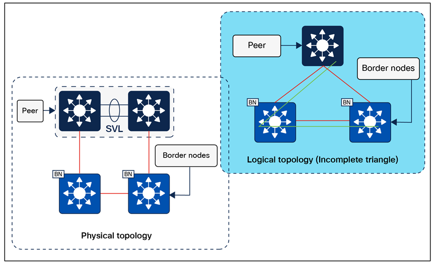
Physical topology – Large site reference design
Large site considerations
Cisco Catalyst Center and the primary ISE Policy Administration node are generally deployed at a large site location.
Control plane nodes and border nodes should be dedicated devices deployed as redundant pairs. Dedicated control plane nodes should be connected to each core switch to provide for resiliency and to have redundant forwarding paths. If interfaces and fiber are available, crosslink the control plane nodes to each other, though this is not a requirement; it simply provides another underlay forwarding path.
One or more wireless controller HA-SSO pairs are deployed with redundant physical connectivity to a services block using Layer 2 port channels. The services block is commonly part of the on-premises data center network.
Dedicated internal border nodes are sometimes used to connect the fabric site to the data center core, while dedicated external border nodes are used to connect the site to the MAN, WAN, and internet. We recommend that you deploy the least number of border nodes that meet network design requirements, because as the quantity of border nodes increases so does the SD-Access administrative effort and routing complexity. Dedicated redundant routing infrastructure and firewalls are used to connect this site to external resources, and border nodes fully mesh to this infrastructure and to each other.
The large site may contain a DMZ where the anchored fabric border and control plane nodes for guest wireless are deployed.
SD-Access for Distributed Campus reference model
SD-Access for Distributed Campus is a solution that connects multiple independent fabric sites together while maintaining the security policy constructs (VRFs and SGTs) across these sites. Control plane signaling from the LISP protocol along with fabric VXLAN encapsulation are used between fabric sites. This maintains the macro- and micro-segmentation policy constructs, VRFs, and SGTs, respectively, between fabric sites. The result is a network that is address-agnostic because end-to-end policy is maintained through group membership.
In the reference topology in Figure 32 below, each fabric site is connected to a Metro Ethernet (Metro-E) private circuit. The deployment is a large enterprise campus with dispersed buildings in a similar geographic area, with each building operating as an independent fabric site. The border nodes connected to this circuit are configured as external borders colocated with a control plane node. IGP peering occurs across the circuit to provide IP reachability between the loopback interfaces (RLOCs) of the devices. The Metro-E circuit is used as the SD-Access transit between the fabric sites.
The headquarters location has direct internet access, and one of the fabric sites (Fabric Site 1) has connections to the data center where shared services are deployed. Internal border nodes at Fabric Site 1 import (register) the data center prefixes into the overlay space so the VNs in each fabric site can access these services. Traffic destined for internet prefixes is forwarded back to the headquarters location so that it can be processed through a common security stack before egressing to the outside world. The transit control plane nodes are deployed in their own area, accessible through the SD-Access transit Metro-E network, though not in the direct forwarding path between fabric sites.
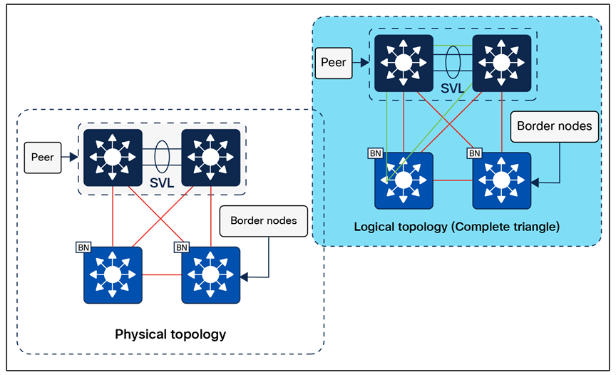
Physical topology – SD-Access for Distributed Campus reference design
Distributed Campus considerations
The core components enabling the Distributed Campus solution are the SD-Access transit and the transit control plane nodes. Both core components are architectural constructs present and used only in Distributed Campus deployments. The SD-Access transit is simply the physical network connection between fabric sites in the same city, on the same WAN, or between buildings in a large enterprise campus.
Reference model circuit for the SD-Access transit
The SD-Access transit, the physical network between fabric sites, should have campus-like connectivity. The same encapsulation method that is used by nodes within a fabric site is used between sites through the SD-Access transit. This physical network should therefore strive for the same latency, throughput, and connectivity as the campus network itself.
This transit reference model should accommodate the MTU setting used for SD-Access in the campus network (typically 9100 bytes, but can be as low as 1550 bytes with a well-considered application and transit MTU design). The physical connectivity is usually direct fiber connections, leased dark fiber, Ethernet over wavelengths on a dense wavelength division multiplexing (DWDM) system, Metro-E system (virtual private LAN service, etc.), or occasionally MPLS.
It is possible to support an SD-Access transit on circuit types with criteria different from those listed above. The primary requirement is to support jumbo frames across the circuit to carry the fabric-encapsulated packets without fragmentation. The latency supported by Cisco Catalyst Center itself, as described in the Scale and Latency section, is the maximum supported latency for these non-campus-like circuits.
Key considerations for SD-Access transits
The SD-Access transit (the physical network) between sites is best represented, and most commonly deployed, as direct or leased fiber over a Metro-E system. In SD-Access, this is commonly done using the IS-IS routing protocol, although other IGPs are supported, as listed in the Underlay Network Design section.
IP reachability must exist between fabric sites. Specifically, there must be a known underlay route between the Loopback 0 interfaces on all border nodes connected to the SD-Access transit. Existing BGP configurations and possible BGP peering on the transit control plane nodes could have complex interactions with the fabric configuration and should be avoided if possible.
A LISP/BGP SD-Access transit has BGP private AS 65540 reserved for use on the transit control plane nodes and automatically provisioned by Cisco Catalyst Center. It should not be used elsewhere in the deployment. A LISP Pub/Sub SD-Access transit does not have BGP present within the SD-Access transit. LISP Pub/Sub is the recommended control plane architecture.
Traversing the transit control plane nodes in the data forwarding path between sites is not recommended. Transit control plane nodes should always be deployed as matching pairs of devices to provide resiliency and high availability.
Transit control plane node considerations
The transit control plane nodes do not have to be physically deployed in the transit area (the connection between sites), although common topology documentation often represents them in this way. These devices are generally deployed in their own dedicated location accessible through the physical transit. While this is not a requirement, it is a recommended practice.
The transit control plane nodes cannot be colocated with any other fabric role. They should be highly available through redundant physical connections. A switching platform is generally recommended for the transit control plane role.
This chapter is organized into the following sections:
| Chapter |
Section |
| Migration to SD-Access |
Greenfield SD-Access networks can be created by adding the infrastructure components, interconnecting them, and using Cisco Catalyst Center with Cisco Plug and Play and LAN Automation to automate provisioning of the network architecture from the ground up. Migrating an existing network requires some additional planning, however. Here are some considerations:
● Does the network require reconfiguration into a Layer 3 routed access model?
● Do the components in the network support the desired scale for the target SD-Access topologies, or do the hardware platforms and software need to be upgraded?
● Is the organization ready for changes in IP addressing and DHCP scope management?
● What is the strategy for integrating new overlays with common services (for example, internet, DNS/DHCP, data center applications)?
● Are SGTs or dynamic ACLs already implemented, and where are the policy enforcement points? If SGTs and multiple overlays are used to segment and virtualize within the fabric, what requirements exist for extending them beyond the fabric? Is infrastructure in place to support Cisco TrustSec, VRF-lite, MPLS, and other technologies necessary to extend and support the segmentation and virtualization?
● Can wireless coverage within a roaming domain be upgraded at a single point in time, or does the network need to rely on over-the-top strategies?
There are three primary approaches when migrating an existing network to SD-Access:
● Parallel: An SD-Access network is built next to an existing brownfield network. Switches are moved from the brownfield network to the SD-Access network by physically patching cables. This approach makes change management and rollback extremely simple. However, the parallel network requires additional rack space, power, and cabling infrastructure beyond what is currently consumed by the brownfield network.
● Incremental: This strategy moves a traditional switch from the brownfield network and converts it to an SD-Access fabric edge node. The Layer 2 border handoff, discussed later, is used to accomplish this incremental migration. This strategy is appropriate for networks that have equipment already in place that is capable of supporting SD-Access, or where there are environmental constraints such as lack of space and power.
● Hybrid: The hybrid approach uses a combination of the parallel and incremental approaches. For example, a new pair of core switches is configured as border nodes, control plane nodes are added and configured, and the existing brownfield access switches are converted to SD-Access fabric edge nodes incrementally.
Imagine a sample network within a building consisting of two floors, with its SSID managed by a WLC on campus. When migrating to fabric wireless, it is important to understand that there will not be seamless roaming between the existing SSID and the fabric SSID to which users will be migrated. APs connect to access switches and create CAPWAP tunnels to the centralized WLC, which handles all wireless management, control, and data traffic.
To integrate wireless into Cisco SD-Access fabric, start by creating a wired fabric on the existing network in the building. The creation of the wired fabric can follow any of the standard models explained above: parallel, incremental, or hybrid. Once the access layer switch to which the AP is connected becomes a fabric edge, users can still connect to the existing SSID and be centrally switched, allowing the wireless network to operate on top of the fabric without significantly impacting existing wireless networks during the wired network migration into the fabric.
We support a brownfield WLC when moving toward fabric, but this brownfield WLC should be compatible with the SD-Access compatibility matrix regarding the Cisco IOS XE images and platforms used. Once the brownfield WLC is discovered via Cisco Catalyst Center, Catalyst Center will understand the existing configuration on the WLC and will not modify it.
The migration to fabric wireless can be carried out in phases, with the smallest unit of migration being a floor within the site hierarchy. An administrator also has the option to migrate a building or area. The right step depends on the environment. By creating a wireless network profile, configuring the SSID as fabric-enabled, and assigning it to the specific floor where the migration will occur, you can gradually transition your existing SSID from over the top (OTT) to fabric-enabled. This phased approach facilitates a smooth and controlled migration process. Once all floors, buildings, or areas are mapped to the fabric-based SSID, the transition to fabric-enabled wireless is complete. At this stage, you can also define segmentation policies.
A critical consideration during the migration phase is the lack of seamless roaming support between SSIDs operating in OTT mode and those operating in fabric mode. You must define an IP pool that does not overlap with the OTT SSID during migration.
If you have an existing WLC, you can reuse it to manage both a fabric site and traditional wireless networks. It is important to note that once the WLC is converted to manage a fabric site, it can oversee a single fabric site along with multiple traditional wireless sites.
When a traditional network is migrating to an SD-Access network, the Layer 2 border handoff is a key strategic feature when endpoint IP addresses cannot change or endpoints must reside in the same Layer 2 switching domain. Endpoints can remain in place in the traditional network while communication and interaction are tested with the endpoints in the fabric without needing to redo the IP addresses of these hosts. Hosts can then be migrated over to fabric entirely either through a parallel migration, which involves physically moving cables, or through an incremental migration of converting a traditional access switch to an SD-Access fabric edge node.
For OT, IoT, and building management systems (BMS) migrating to SD-Access, the Layer 2 border handoff can be used in conjunction with Layer 2 flooding. This enables Ethernet broadcast wake-on-LAN capabilities between the fabric site and the traditional network and allows OT/BMS systems that traditionally communicate via broadcast to migrate incrementally into the fabric.
The appendices are as follows:
| Chapter |
Section |
| SD-Access fabric protocols |
|
| References used in this guide |
|
| Glossary of terms and acronyms |
|
| Recommended for you and additional resources |
Appendix A. SD-Access fabric protocols
This appendix is organized into the following sections:
| Appendix |
Section |
| SD-Access fabric protocols |
RFC 7348 defines the use of virtual extensible LAN (VXLAN) as a way to overlay a Layer 2 network on top of a Layer 3 network. Each overlay network is called a VXLAN segment and is identified using a 24-bit VXLAN network identifier, which supports up to 16 million VXLAN segments.
The SD-Access fabric uses the VXLAN data plane to provide transport of the full original Layer 2 frame and additionally uses LISP as the control plane to resolve endpoint-to-location (EID-to-RLOC) mappings. The SD-Access fabric replaces 16 of the reserved bits in the VXLAN header to transport up to 64,000 SGTs using a modified VXLAN-GPO (sometimes called VXLAN-GBP) format described in https://tools.ietf.org/html/draft-smith-vxlan-group-policy-04.
The Layer 3 VNI maps to a virtual routing and forwarding (VRF) instance for Layer 3 overlays, whereas a Layer 2 VNI maps to a VLAN broadcast domain, both providing the mechanism to isolate the data and control plane to each individual virtual network. The SGT carries group membership information of users and provides data plane segmentation inside the virtualized network.
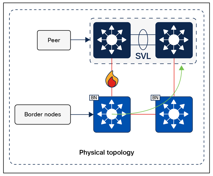
VXLAN-GBP header (also known as VXLAN-GPO)
RFC 6830 through RFC 6836, along with later RFCs, define LISP as a network architecture and set of protocols that implement a new semantic for IP addressing and forwarding. In traditional IP networks, the IP address is used to identify both an endpoint and its physical location as part of a subnet assignment on a router. In a LISP-enabled network, an IP address or MAC address is used as the EID for an endpoint, and an additional IP address is used as an RLOC to represent the physical network device the endpoint is connected either directly to or directly through, such as with an access point or extended node. The Loopback 0 address of the network device is used as the RLOC address. The EID and RLOC combination provides the necessary information for traffic forwarding. The RLOC address is part of the underlay routing domain, and the EID can be assigned independently of the location.
The LISP architecture requires a mapping system that stores and resolves EIDs to RLOCs. This is analogous to using DNS to resolve IP addresses for host names. EID prefixes (either IPv4 addresses with /32 masks, MAC addresses, or IPv6 addresses with /128 masks) are registered with the map server along with their associated RLOCs. When sending traffic to an EID, a source RLOC queries the mapping system to identify the destination RLOC for traffic encapsulation. As with DNS, a local node probably does not have information about everything in a network but instead asks for the information only when local hosts need it to communicate (known as a pull model). This information is then cached for efficiency.
Although a full understanding of LISP and VXLAN is not required to deploy a fabric in SD-Access, it is helpful to understand how these technologies support the deployment goals. Included benefits provided by the LISP architecture are:
● Network virtualization: A LISP instance ID (IID) is used to maintain independent VRF and VLAN topologies. From a data-plane perspective, the LISP IID maps to either a Layer 2 or Layer 3 VNI.
● Subnet stretching: A single subnet can be extended to exist at multiple RLOCs. The separation of EID from RLOC enables the capability to extend subnets across different RLOCs. As a result of the availability of the anycast gateway across multiple RLOCs, the client configuration (IP address, subnet, and gateway) can remain unchanged, even as the client moves across the stretched subnet to different physical attachment points.
● Smaller routing tables: Only RLOCs need to be reachable in the global routing table for communication within a fabric site. Local EIDs (connected endpoints) are cached at the local node, while remote EIDs (endpoints connected to or through other fabric devices) are learned through conversational learning. Conversational learning is the process of populating forwarding tables with only endpoints that are communicating through the node. This allows for efficient use of forwarding tables.
Appendix B. References used in this guide
Cisco Catalyst Center Data Sheet: SD-Access Scale
Cisco Catalyst Center Data Sheet: Fabric VN Scale
Cisco Catalyst Center High Availability Guide
Cisco Catalyst Center Latency Requirements
Cisco Catalyst Center Release Notes
Cisco Catalyst Center SD-Access LAN Automation Deployment Guide
Cisco Validated Designs for the Extended Enterprise: Non-Fabric and SD-Access Fabric Design Guide
Performance and Scalability Guide for Cisco Identity Services Engine
Cisco Live - Cisco SD-Access - BRKENS-2810.
Cisco Live - Cisco SD-Access Migration Tools and Strategies – BRKENS-2827
Cisco on Cisco Best Practices: Cisco High Availability LAN
AAA—Authentication, authorization, and accounting
ACL—Access control list
AD—Microsoft Active Directory
AFI—Address Family Identifier
AMP—Advanced Malware Protection
AP—Access point
API—Application programming interface
ASM—Any-Source Multicast (PIM)
Auto-RP—Cisco Automatic Rendezvous Point protocol (multicast)
AVC—Application Visibility and Control
BFD—Bidirectional Forwarding Detection
BGP—Border Gateway Protocol
BMS—Building management system
BSR—Bootstrap router (multicast)
CAPWAP—Control and Provisioning of Wireless Access Points Protocol
CDP—Cisco Discovery Protocol
CEF—Cisco Express Forwarding
CMD—Cisco Metadata
CPU—Central processing unit
DC—Data center
DHCP—Dynamic Host Configuration Protocol
DM—Dense mode (multicast)
DMVPN—Dynamic Multipoint Virtual Private Network
DMZ—Demilitarized zone (firewall/networking construct)
DNS—Domain Name System
DORA—Discover, Offer, Request, ACK (DHCP process)
DWDM—Dense Wavelength Division Multiplexing
ECMP—Equal-cost multipath
EID—Endpoint Identifier
EIGRP—Enhanced Interior Gateway Routing Protocol
ETR—Egress Tunnel Router (LISP)
EVPN—Ethernet Virtual Private Network (BGP EVPN with VXLAN data plane)
FHR—First-hop router (multicast)
FHRP—First-Hop Redundancy Protocol
GBAC—Group-based access control
GRE—Generic Routing Encapsulation
GRT—Global routing table
HA—High availability
HQ—Headquarters
HSRP—Cisco Hot-Standby Routing Protocol
HTDB—Host-tracking database (SD-Access control plane node construct)
IBNS—Identity-Based Networking Services (IBNS 2.0 is the current version)
ICMP— Internet Control Message Protocol
IDF—Intermediate distribution frame; essentially a wiring closet
IEEE—Institute of Electrical and Electronics Engineers
IETF—Internet Engineering Task Force
IGP—Interior Gateway Protocol
IID—Instance-ID (LISP)
IOE—Internet of Everything
IoT—Internet of Things
IP—Internet Protocol
IPAM—IP Address Management
IPS—Intrusion prevention system
IPsec—Internet Protocol Security
ISE—Cisco Identity Services Engine
ISR—Intra-subnet routing
IS-IS—Intermediate System to Intermediate System routing protocol
ITR—Ingress Tunnel Router (LISP)
LACP—Link Aggregation Control Protocol
LAG—Link Aggregation Group
LAN—Local area network
L2 VNI—Layer 2 Virtual Network Identifier; as used in SD-Access fabric, a VLAN
L3 VNI— Layer 3 Virtual Network Identifier; as used in SD-Access Fabric, a VRF
LHR—Last-hop router (multicast)
LISP—Location Identifier Separation Protocol
MAC—Media Access Control address (OSI Layer 2 address)
MAN—Metro area network
MEC—Multichassis EtherChannel, sometimes referenced as MCEC
MDF—Main distribution frame; essentially the central wiring point of the network
MnT—Monitoring and Troubleshooting node (Cisco ISE persona)
MPLS—Multiprotocol Label Switching
MR—Map resolver (LISP)
MS—Map server (LISP)
MSDP—Multicast Source Discovery Protocol (multicast)
MTU—Maximum transmission unit
NAC—Network Access Control
NAD—Network access device
NAT—Network Address Translation
NBAR—Cisco Network-Based Application Recognition (NBAR2 is the current version).
NFV—Network functions virtualization
NSF—Non-stop forwarding
OSI—Open Systems Interconnection model
OSPF—Open Shortest Path First routing protocol
OT—Operational technology
PAN—Primary Administration node (Cisco ISE persona)
PD—Powered devices (PoE)
PETR—Proxy-Egress Tunnel Router (LISP)
PIM—Protocol-Independent Multicast
PITR—Proxy-Ingress Tunnel Router (LISP)
PnP—Plug and Play
PoE—Power over Ethernet (generic term, may also refer to IEEE 802.3af, 15.4W at PSE)
PoE+—Power over Ethernet Plus (IEEE 802.3at, 30W at PSE)
PSE—Power sourcing equipment (PoE)
PSN—Policy Service node (Cisco ISE persona)
pxGrid—Platform Exchange Grid (Cisco ISE persona and publisher/subscriber service)
PxTR—Proxy-Tunnel Router (LISP – device operating as both a PETR and PITR)
QoS—Quality of service
RADIUS—Remote Authentication Dial-In User Service
REST—Representational State Transfer
RFC—Request for Comments document (IETF)
RIB—Routing Information Base
RLOC—Routing locator (LISP)
RP—Rendezvous point (multicast)
RPF—Reverse path forwarding
RR—Route reflector (BGP)
RTT—Round-trip time
SA—Source Active (multicast)
SAFI—Subsequent Address Family Identifiers (BGP)
SD—Software-defined
SDN—Software-defined networking
SGACL—Security-group ACL
SGT—Security group tag, also referred as scalable group tag
SM—Spare-mode (multicast)
SNMP—Simple Network Management Protocol
SSID—Service Set Identifier (wireless)
SSM—Source-Specific Multicast (PIM)
SSO—Stateful Switchover
STP—Spanning-Tree Protocol
SVI—Switched virtual interface
SWIM—Software Image Management
SXP—Scalable Group Tag Exchange Protocol
TACACS+—Terminal Access Controller Access-Control System Plus
TCP—Transmission Control Protocol (OSI Layer 4)
UDP—User Datagram Protocol (OSI Layer 4)
UPOE—Cisco Universal Power Over Ethernet (60W at PSE)
UPOE+— Cisco Universal Power Over Ethernet Plus (90W at PSE)
URL—Uniform Resource Locator
VLAN—Virtual local area network
VN—Virtual network, analogous to a VRF in SD-Access
VNI—VXLAN Network Identifier (VXLAN)
vPC—Virtual port channel (Cisco Nexus)
VPLS—Virtual Private LAN Service
VPN—Virtual private network
VPNv4—BGP address family that consists of a Route-Distinguisher (RD) prepended to an IPv4 prefix
VRF—Virtual routing and forwarding
VSL—Virtual Switch Link (Cisco VSS component)
VSS—Cisco Virtual Switching System
VXLAN—Virtual Extensible LAN
WAN—Wide-area network
WLAN—Wireless local area network (generally synonymous with IEEE 802.11-based networks)
WoL—Wake on LAN
xTR—Tunnel Router (LISP – device operating as both an ETR and ITR)
Appendix D. Recommended for you
Cisco SD-Access Fabric Resources - Cisco Community
Cisco SD-Access Segmentation Design Guide
Cisco Software-Defined Access for Industry Verticals: From Design to Migration
SD-Access Deployment Using Cisco Catalyst Center
YouTube playlist, Cisco Catalyst Center
YouTube playlist, Cisco ISE - Identity Services Engine
YouTube playlist, Cisco SD-Access