SD-Access Deployment Using Cisco Catalyst Center
Available Languages
Bias-Free Language
The documentation set for this product strives to use bias-free language. For the purposes of this documentation set, bias-free is defined as language that does not imply discrimination based on age, disability, gender, racial identity, ethnic identity, sexual orientation, socioeconomic status, and intersectionality. Exceptions may be present in the documentation due to language that is hardcoded in the user interfaces of the product software, language used based on RFP documentation, or language that is used by a referenced third-party product. Learn more about how Cisco is using Inclusive Language.
- US/Canada 800-553-2447
- Worldwide Support Phone Numbers
- All Tools
 Feedback
 Feedback
About this guide
This guide is intended to provide technical guidance to design, deploy, and operate Cisco software‑defined access (Cisco SD-Access) networks using Cisco Catalyst Center.
The audience for this document includes network design engineers and network operations personnel who need to implement a Cisco SD-Access network within their campus networks using Catalyst Center.
This guide focuses on how to design and deploy a Cisco SD-Access network within an enterprise network using Catalyst Center in day-zero and day-n operation, and how to monitor the overall health of the Cisco SD‑Access network.
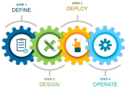
Major sections of this document include:
● The Define section provides a high-level overview of the Cisco SD‑Access, including key components in Cisco SD-Access networks, and design considerations when deploying a Cisco SD-Access wired and wireless network using Catalyst Center.
● The Design section discusses the integration of Catalyst Center with Cisco Identity Services Engine (Cisco ISE); creation of the site hierarchy; configuration of various network services necessary for network operations, such as AAA, DNS, DHCP, NTP, SNMP, and Syslog servers; configuration of wireless settings, including WLANs with SSIDs, VLANs, and RF profiles for the WLAN deployment; enabling fabric site, fabric zones, virtual networks, anycast gateways and associating in fabric sites and configuration of Cisco SD-Access and IP transit.
● The Deploy section discusses discovering devices and provisioning devices in fabric sites as fabric border and control plane node; LAN automation for onboarding day-zero devices and provisioning them as fabric edges; configuring an embedded wireless controller on Catalyst 9000 devices and a standalone wireless controller; configuring layer 3 handoff and layer 2 handoff; enabling multicast.
This section also explains the attributes and features supported in a border configuration and an anycast gateway configuration.
● The Operate section discusses day-n operations in a Cisco SD‑Access network, including onboarding access points (APs), different types of extended nodes and clients, modifying and changing fabric features, replacing faulty devices with RMA procedure, deleting fabric devices from a fabric site, and tearing down fabric sites.
● The Monitor section briefly discusses how Cisco Catalyst Assurance can be used to monitor and troubleshoot the Cisco SD-Access network deployment. Cisco SD-Access system health tools are used to monitor the health of the Cisco SD‑Access application. Additionally, the Cisco SD-Access Compatibility Matrix check is used to prevent the addition of unsupported devices or devices running unsupported software versions.
This section provides a high-level overview of the Cisco SD-Access architecture and the design considerations for deploying a wired and a wireless campus network through Catalyst Center.
Cisco SD-Access solution
What is Cisco SD-Access
Cisco SD-Access is the evolution from traditional campus designs to networks that directly implement the intent of an organization. Cisco SD-Access is software running on Catalyst Center that automates wired and wireless campus networks.
Fabric technology, an integral part of Cisco SD-Access, provides wired and wireless campus networks with programmable overlays and easy-to-deploy virtual networks (VNs), permitting a physical network to host one or more logical networks to meet the design intent. In addition to VNs, fabric technology in the campus network enhances control of communications, providing software-defined segmentation and policy enforcement based on user identity and group membership. Using Catalyst Center to automate the creation of VNs with integrated security and segmentation reduces operational expenses and reduces risk. Catalyst Assurance and Analytics provide network performance, network insights, and telemetry.
Why Cisco SD-Access
Cisco SD-Access is superior to a traditional network deployment for these primary reasons:
● Complexity reduction and operational consistency achieved through orchestration and automation
● Multitier segmentation incorporating group-based policies
● Dynamic policy mobility provided for wired and wireless clients
Cisco SD-Access is built on an intent-based networking foundation that includes visibility, automation, security, and simplification. Using Catalyst Center automation and orchestration, network administrators can make changes across the entire enterprise environment through an intuitive, graphical user interface (GUI).
Cisco SD-Access secures the network at the macrosegmentation and microsegmentation levels using virtual routing and forwarding (VRF) tables and security group tags (SGTs). This multitier segmentation is not optimal in traditional networks.
With multitier segmentation, all the security context associated with a user or a device are dynamically assigned during network connection authentication. Cisco SD-Access provides the same security policy capabilities for wired and wireless attachments, which maintains secure policy consistency when the user or the device changes attachment type.
Instead of relying on IP-based security rules like a traditional network, Cisco SD-Access relies on centralized group-based security rules using SGTs that are IP address-agnostic. As a user or device moves from location to location and changes IP addresses, the security policy remains the same because the group membership is location-independent for network access. Network administrators do not have to create as many rules nor manually update them on different devices, which leads to a more dynamic and stable environment for network consumers.
Cisco SD-Access solution components
The Cisco SD-Access solution uses these fundamental pillars:
● Catalyst Center
● Cisco Identity Services Engine (Cisco ISE)
● Wired and wireless device platform that supports fabric connectivity
Catalyst Center
Catalyst Center is the centralized manager running a collection of applications and services powering the Cisco Digital Network Architecture (Cisco DNA). Catalyst Center begins with the foundation of a digital-ready infrastructure that includes routers, switches, APs, and wireless LAN controllers. Automation, analytics, visibility, and management of the Catalyst Center network is enabled through the Catalyst Center software. Cisco SD-Access is part of this software and is used to design, provision, and apply policy, and to help with the creation of an intelligent wired and wireless campus network.
Cisco ISE
Cisco ISE is a secure network access platform that enables increased management awareness, control, and consistency for users and devices accessing a network. Cisco ISE is an integral component of Cisco SD-Access for implementing a network access control policy. Cisco ISE performs policy implementation that enables dynamic mapping of users and devices to scalable groups. It also simplifies end-to-end security policy enforcement. Within Cisco ISE, users and devices appear in a simple and flexible interface. Cisco ISE integrates with Catalyst Center using the Cisco Platform Exchange Grid (pxGrid) and Representational State Transfer Application Programming Interfaces (REST APIs) for endpoint event notifications and the automation of policy configurations on Cisco ISE.
The Cisco SD-Access solution integrates Cisco TrustSec Microsegmentation by supporting end-to-end group-based policy with SGTs. SGTs are a metadata value that is transmitted in the header of fabric-encapsulated packets. While SGTs are administered by Cisco ISE through the integrated REST APIs, Catalyst Center is used as the dashboard to manage and create SGTs and define their policies. Group and policy services are managed by Cisco ISE and coordinated by the Catalyst Center policy authoring workflows. In a Cisco SD-Access network, policy management is streamlined by integrating Cisco ISE with Catalyst Center, allowing for dynamic mapping of users and devices to security groups. This simplifies end-to-end security policy management and enforcement by providing a more scalable solution compared to traditional network policy implementations that rely on IP access-lists.
Tech tip: Cisco ISE is not mandatory if the Cisco SD-Access solution is using Macrosegmentation.
Network infrastructure
The Cisco SD-Access solution infrastructure includes routers, switches, APs, and wireless LAN controllers. On these devices, Catalyst Center deploys the various fabric roles based on the choices made in the user interface (UI).
Cisco SD-Access architecture overview
The Cisco SD-Access architecture uses fabric technology to support campus networks. This involves creating VNs, known as overlay networks, that operate on top of a physical network, known as an underlay network. This setup allows for the creation of alternative topologies to connect devices, which enhances network flexibility and functionality. This section discusses the Cisco SD-Access operational planes. The fabric underlay and overlay networks introduce shared services that are a shared set of resources accessed by devices in the overlay.
Cisco SD-Access operational planes
These key technologies that make up the Cisco SD-Access solution each do distinct tasks in different network planes of operation:
● Control plane:
Locator ID Separation Protocol (LISP) is used as messaging and the communication protocol between infrastructure devices in the fabric.
● Data plane:
Virtual Extensible LAN (VXLAN) is used as an encapsulation method for the data packets.
● Policy plane:
Cisco TrustSec is used for security and microsegmentation.
● Management plane:
Catalyst Center is used for orchestration, assurance, visibility, and management.
Control plane with LISP
In many networks, the IP address associated with an endpoint defines both its identity and its location in the network. The IP address is used for both network layer identification (who the device is on the network) and as a network layer locator (where the device is in the network, or to which device it is connected).
LISP is a routing architecture that provides new semantics for IP addressing. It allows the separation of identity and location through a mapping relationship of an End Point Identifier (EID) namespace in relationship to its routing locator (RLOC) namespace.
The LISP control plane messaging protocol communicates and exchanges the relationship between the two namespaces. This relationship is called an EID-to-RLOC mapping. The EID and RLOC combination provide all the necessary information for traffic forwarding, even if an endpoint uses the same IP address when appearing in a different network location (associated or mapped behind different RLOCs).
The fabric devices query the control plane node to determine the routing locator associated with the destination address (EID-to-RLOC mapping) and use that RLOC information as the traffic destination.
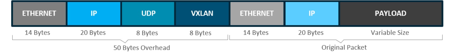
Data plane with VXLAN
VXLAN is a MAC-in-IP encapsulation method for data traffic. It preserves the original Ethernet header from the original frame sent from the endpoint, which allows for the creation of an overlay at layer 2 and at layer 3, depending on the requirements of the original communication. For example, wireless LAN communication uses layer 2 datagram information (MAC addresses) to make bridging decisions without a direct need for layer 3 forwarding logic.
Cisco SD-Access places additional information in the fabric VXLAN header, including alternative forwarding attributes that can be used to make policy decisions by identifying each overlay network using a VXLAN network identifier (VNI). layer 2 overlays are identified with a VLAN to VNI correlation (layer 2 VNI), and layer 3 overlays are identified with a VRF to VNI correlation (layer 3 VNI).
VXLAN encapsulation uses a User Datagram Protocol (UDP) transport. Along with the VXLAN and UDP headers used to encapsulate the original packet, an outer IP and Ethernet header are required to forward the packet across the wire. As shown, these extra headers add 50 bytes of overhead to the original packet, at minimum.
Policy plane with Cisco TrustSec
Cisco TrustSec is an umbrella term for security improvements to Cisco network devices based on the capability to strongly identify users, hosts and network devices within a network. It uses SGTs to represent logical group privilege. The SGT is used in access policies. The SGT is understood by Cisco switches, routers and firewalls, and is used to enforce traffic.
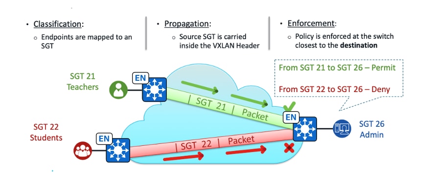
Cisco TrustSec is structured in phases: classification, propagation and enforcement. When users and devices connect to a network, the network assigns a specific security group, called classification. Classification can be based on the results of the authentication or by associating the SGT with an IP, VLAN, or port-profile. After user traffic is classified, the SGT transmits from the point of classification to the location where enforcement actions are applied. This process is known as propagation.
Methods of SGT propagation that Cisco TrustSec uses include:
● Inline tagging:
The SGT is embedded into the Ethernet frame. The ability to embed the SGT within an Ethernet frame requires specific hardware support.
● SGT Exchange Protocol (SXP):
Network devices that do not have hardware support use SXP. SXP pairs the SGT with the IP address mapping. This pairing allows the SGT propagation to continue to the next device in the path. An enforcement device controls traffic based on the tag information.
A Cisco TrustSec enforcement-point can be a Cisco firewall, router, or switch. The enforcement device takes the source SGT and compares it to the destination SGT to determine if the traffic should be allowed or denied.
The key component of Cisco TrustSec is the Cisco ISE. Cisco ISE provisions switches with Cisco TrustSec identities and security group access control lists (SGACLs).
Management plane with Catalyst Center
Catalyst Center enables automation of device deployments and configurations into the network to provide the speed and consistency required for operational efficiency.
Through the automation capabilities, the control plane, data plane, and policy plane for the fabric devices are easily, seamlessly, and consistently deployed. Thorough assurance, visibility and context are achieved for both the infrastructure devices and the endpoints.
A full understanding of LISP and VXLAN is not required to deploy the fabric in Cisco SD-Access, nor is there a requirement to know the details about configuring each individual network component and feature to create the consistent end-to-end behavior offered by Cisco SD-Access. Catalyst Center is an intuitive, centralized management system used to design, provision, and apply policy across the wired and wireless Cisco SD-Access network. It takes the user’s intent and programmatically applies it to network devices.
Fabric underlay
The underlay network is defined by the physical switches and routers used to deploy the Cisco SD-Access network. All network elements of the underlay must establish IP connectivity using a routing protocol. The underlay implementation for Cisco SD-Access uses a structured layer 3 foundation, including campus edge switches, called a layer 3 Routed Access design, instead of random network topologies and protocols. This ensures performance, scalability, resiliency, and deterministic convergence of the network.
In Cisco SD-Access, the underlay switches (edge nodes) support the physical connectivity for users and endpoints. However, end‑user subnets and endpoints are not part of the underlay network. They are part of the automated overlay network.
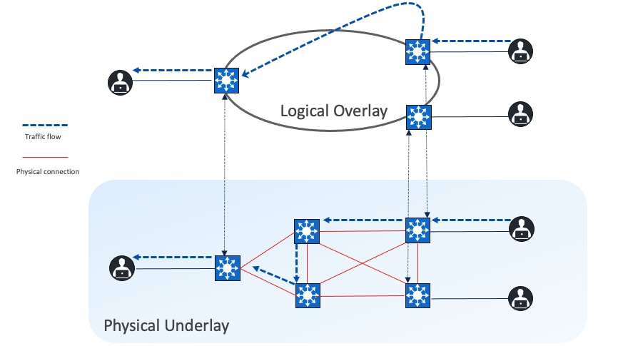
Fabric overlay
An overlay network is created on top of the underlay network through virtualization (VNs). The data plane traffic and control plane signaling are contained within each VN, maintaining isolation among the networks and an independence from the underlay network. Multiple overlay networks can run across the same underlay network through VNs. In Cisco SD-Access, the user-defined overlay networks are provisioned as VRF instances that provide separation of routing tables.
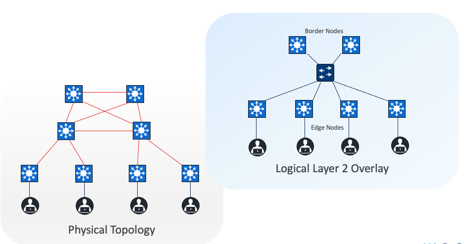
Cisco SD-Access allows for the extension of layer 2 and layer 3 connectivity across the overlay through the services provided through LISP. layer 2 overlay services emulate a LAN segment to transport layer 2 frames by carrying a subnet over the layer 3 underlay as shown in the figure.
Layer 3 overlays abstract the IP-based connectivity from the physical connectivity, as shown in the figure. This allows multiple IP networks to be part of each VN. Each layer 3 overlay, its routing tables, and its associated control planes are completely isolated from each other.
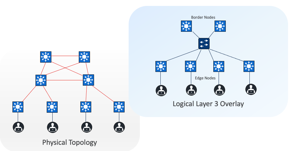
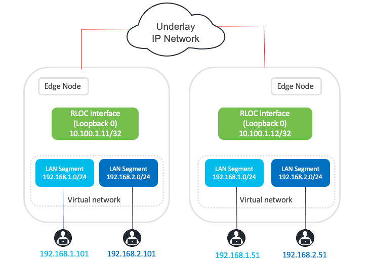
Figure 5 shows an example of two subnets that are part of the overlay network. The subnets stretch across physically separated layer 3 edge node devices. The RLOC interfaces, or Loopback0 interfaces in Cisco SD-Access, are the only underlay routable addresses that are required to establish connectivity between endpoints within the same VN.
In all network deployments there is a common set of resources required by every endpoint, the common examples include:
● Identity services (for example: AAA/RADIUS)
● Domain name services (DNS)
● Dynamic host configuration protocol (DHCP)
● IP address management (IPAM)
● Monitoring tools (for example: SNMP)
● Data collectors (for example: NetFlow and syslog)
● Internet access
● Other infrastructure elements
These common resources are often called shared services. These shared services generally reside outside of the Cisco SD-Access fabric. In most cases, such services reside in the data center and are part of the Global Routing Table (GRT) or another dedicated VRF.
Cisco SD-Access fabric clients operate in overlay virtual networks. If the shared services are part of the global routing space or part of another VRF, some method of VRF route leaking between user VRFs and shared services is required. This is achieved using a peer device or firewall.
Cisco SD-Access network overview
Fabric site
A fabric site is composed of a unique set of devices operating in a fabric role along with the intermediate nodes that are used to connect those devices. A fabric site must have a border node and a control plane node, and often have fabric edge nodes. A fabric site can also have an associated fabric wireless LAN controller (WLC) and a Cisco ISE Policy Service Node (PSN).
Fabric zone
Fabric zones are child sets of a parent fabric site. Without fabric zones, all IP pools are configured on all the fabric edge nodes leading to all subnets on every fabric edge node. Zones give the flexibility to have specific subnets on specific fabric edge nodes. This configuration provides a way to manage large-scale deployments of fabric edge nodes in a single fabric site based on smaller locations. For example, a fabric site may include ten buildings. There may not be a need to have all the IP pools across all the buildings. Enabling fabric zones on buildings ensures that some IP pools are only available in some buildings.
Transits
Transits can connect to multiple fabric sites or can connect a fabric site to nonfabric domains, such as a data center or the internet. Transits are a Cisco SD-Access construct that defines how Catalyst Center automates the border node configuration for connections between fabric sites or between a fabric site and an external domain. Transit types include:
IP-based transit
With IP-based transits, the fabric VXLAN header is added or removed by the fabric border nodes when a packet enters or exits the fabric sites. After the VXLAN header is removed, packets are forwarded using traditional routing and switching protocols between fabric sites. IP-based transits are provisioned with VRF-LITE connections to upstream peer devices that typically connect to a data center, WAN, or the internet. An IP transit can also be used to connect to shared services using a VRF-aware peer.
Cisco SD-Access transit
Using the Cisco SD-Access transit, packets are encapsulated with VXLAN between sites. This natively carries VRF and SGT policy constructs between fabric sites. Key considerations when using Cisco SD‑Access transit include:
● Connections should support the recommended Maximum Transmission Unit (MTU) size of 9100 bytes along the entire path between fabric site borders.
● IP reachability must exist between fabric sites. Specifically, there must be a known underlay route between all fabric site borders and transit control plane nodes. The default route cannot be used for this purpose.
Cisco SD-Access transit is recommended for customers who require policy enforcement expansion across different fabric sites.
VNs
Cisco SD-Access provides layer 3 and layer 2 connectivity across the overlay using VNs.
Layer 3 overlays emulate an isolated routing table and transport layer 3 frames over the layer 3 network. This type of overlay is called a layer 3 Virtual Network (L3VN). An L3VN is analogous to a Virtual Routing and Forwarding (VRF) table in a traditional network. Endpoint IDs (IPV4/IPV6 addresses) are routed within an L3VN.
Layer 2 overlays emulate a LAN segment and transport layer 2 frames over the layer 2 network. This type of overlay is called a layer 2 Virtual Network (L2VN). An L2VN is analogous to a VLAN in a traditional network. Endpoint IDs (MAC addresses) are switched within an L2VN.
Anycast gateway
Anycast gateway provides a default gateway for IP-capable endpoints in a Cisco SD-Access network. The anycast gateway is represented as a Switched Virtual Interface (SVI) with a hard-coded MAC address that is uniform across all edge nodes within a fabric site. This allows a subnet to be stretched across the Cisco SD-Access network. The subnet being stretched allows a host to move around anywhere in the fabric site but maintain the same gateway IP address and MAC address.
SGTs
SGTs are metadata values indicating the privileges of the source within the entire network. There are several methods to propagate SGTs. Within the Cisco SD-Access fabric, SGTs are propagated in the header of the VXLAN encapsulated packets. Outside the Cisco SD-Access fabric, SGTs can be maintained using inline tagging, SXP, static binding, and so on.
With identity services provided through Cisco ISE, users and devices connected to the fabric can be dynamically mapped to an SGT. This approach simplifies the management and enforcement of security policies across the network, providing a more scalable solution compared to traditional network policy implementations that rely on IP access-lists.
SGT details:
● Endpoints are not aware of SGT mappings
● SGTs Range is 1~65533, SGT 0 is used as ‘Unknown’
● Catalyst Center and Cisco ISE configurable SGT value is 2~65519
Segmentation
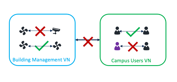
Cisco SD-Access creates macrosegmentation and microsegmentation.
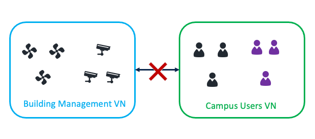
Macrosegmentation as first-level segmentation uses VNs. Users and devices can be put into different VNs that enable isolation between them. Endpoints in different VNs cannot communicate with each other.
Microsegmentation as second-level segmentation is achieved using SGTs. SGTs are used to segment inside the VNs. SGT permits or denies communication within a given VN depending on the Default Policy setting. When the Default Policy setting is to permit, users and devices in the same VN can communicate with each other. SGTs can be used to deny communication within the VN. When the Default Policy setting is to deny, users and devices in the same VN cannot communicate with each other. SGTs can be used to permit communication within the VN.
The microsegmentation is using the Cisco TrustSec solution defined by these primary concepts: classification, propagation, and enforcement. Catalyst Center automates the security policy, including security groups, contracts and policies, and synchronizes with Cisco ISE. The classification, assignment of security groups, and handling of policy downloads is the responsibility of the Cisco ISE. For more details, see End-to-end microsegmentation.
Cisco SD-Access fabric roles
For a fabric site to function, it needs at least a fabric control plane and a fabric edge. A fabric border is also needed if connected to the external world. A network administrator can add other fabric devices, such as a fabric wireless controller and fabric AP for fabric wireless deployment, an extended node to expand layer 2 access to the fabric edge, and so on. Some fabric roles can be colocated in a single device.
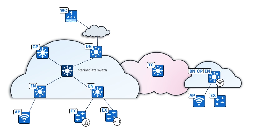
● Control plane node 
A map server that receives registrations from edges, border nodes and fabric wireless controllers with local endpoints. A control plane node is also a map resolver (MR) that resolves requests from edges and borders to locate the destination endpoints.
● Border node 
The gateway between the Cisco SD-Access fabric site and the networks external to the fabric. The border node acts as a gateway for entering and exiting a fabric site, handling network virtualization and SGT propagation to the rest of the network. Layer 3 border nodes can be internal border, external border, and anywhere border types.
● Edge node 
A fabric device that connects endpoints to the Cisco SD-Access fabric and optionally enforces microsegmentation policy. These devices encapsulate at ingress and decapsulate at egress, to forward traffic to and from the endpoints connected to the fabric network. It provides an anycast gateway for the connected wired and wireless endpoints and is responsible for authenticating and authorizing.
● Access point 
A fabric-mode associated with a fabric wireless LAN controller configured with fabric-enabled SSID. It connects wireless endpoints to the Cisco SD-Access fabric.
● Wireless controller 
A controller that connects fabric APs to the Cisco SD-Access fabric. The fabric wireless controller registers the MAC address of wireless clients with the fabric control plane node.
● Extended node 
A layer 2 port extension to fabric edge nodes that optionally enforces a microsegmentation policy to the connected endpoints. Endpoints, including fabric APs, can connect directly to the extended node. Extended node types supported by Catalyst Center include:
◦ Extended nodes: Microsegmentation is not supported.
◦ Policy extended nodes : Microsegmentation uplink support is configured as a port channel.
◦ Supplicant-based extended nodes  : Microsegmentation uplink port support is dot1x authenticated.
● Intermediate nodes  (underlay)
Part of the layer 3 underlay network used for interconnections among the fabric devices. They are not limited to a single layer of devices. An intermediate node is not a fabric role.
● Transit control plane node 
The transit control plane is mandatory when using Cisco SD-Access transit. Functions similarly to a site-local control plane node, except it serves the entire Cisco SD-Access transit.
Multiple fabric roles can be colocated in a single device, such as a border with a control plane colocation, a border with a control plane and a wireless controller colocation, a border with a controller plane and an edge colocation, and so on. A transit control plane node is a dedicated device. Colocation of a transit control plane is not supported.
● Embedded wireless controller (EWC) on a Catalyst 9000 device:
Enabled in Catalyst 9000 devices (EWC on Catalyst 9000) with a wireless subpackage. It is supported when Catalyst 9000 devices are in a fabric with the border with control plane fabric role  , edge fabric role
  , or border with control plane and edge fabric role.
Note: Some wireless features such as RLAN and the assurance monitoring tool are not supported in EWC on Catalyst 9000 devices. Up to two EWC on Catalyst 9000 devices can be enabled in a fabric site. EWC on Catalyst 9000 devices are only recommended in a small branch. EWC on Catalyst 9000 devices only support fabric SSID.
● Fabric in a box (FiaB) 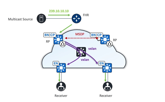
Combines the fabric roles of a border node, a control plane node, and an edge node on the same device. This may be a single switch, a switch with hardware stacking, or a StackWise Virtual deployment. The same switch can also serve as an EWC for fabric-enabled wireless designs.
Platform fabric role support
Cisco router platforms such as the ASR 1000 series, ISR series, and Catalyst 8000 series routers are mainly supported as border and control plane devices. Catalyst 9000 switches support most of the fabric roles as shown in Table 1:
Table 1. Fabric roles supported by Cisco Catalyst 9000 series switches
| Platform family |
Edge node |
Control plane node |
Border node |
Extended node |
Embedded wireless controller |
| Cisco Catalyst 9200 Series |
✔ |
— |
— |
✔ |
— |
| Cisco Catalyst 9300 Series |
✔ |
✔ |
✔ |
✔ |
✔ |
| Cisco Catalyst 9400 Series |
✔ |
✔ |
✔ |
✔ |
✔ |
| Cisco Catalyst 9500 Series |
✔ |
✔ |
✔ |
✔ |
✔ |
| Cisco Catalyst 9600 Series |
— |
✔ |
✔ |
— |
— |
Cisco IE 3000 series, IE 4000 series, and IE 9000 series switches mainly serve as an extended node. IE 9000 is also supported as a fabric edge device.
See the Cisco SD-Access Compatibility Matrix for a detailed list of supported platforms, supported fabric roles, and recommended software versions.
Cisco SD-Access features and capabilities
LISP Publisher/Subscriber (LISP Pub/Sub)
As discussed in the previous section, the LISP protocol is used as the control plane in a Cisco SD-Access solution to track the endpoint IDs (EID) and its routing locator (RLOC). Based on route distribution methods, LISP with Border Gateway Protocol (BGP) and LISP Pub/Sub are supported.
LISP BGP uses concurrent LISP and BGP protocols to distribute reachability information. LISP Pub/Sub uses a publish and subscribe model for routing information through native LISP.
LISP Pub/Sub is recommended for all new deployments with device image 17.6 and later versions. Currently, migration from LISP/BGP to LISP Pub/Sub is not supported by Catalyst Center, but it is on the roadmap.
Areas LISP Pub/Sub offers additional advantages over LISP/BGP include:
● Removes dependency on internal BGP (iBGP) in the fabric and uses LISP for all fabric related operations (in case of a non-colocated scenario where the control node is different from the border node, iBGP is configured to support Cisco SD-Access used as a transit between two external networks).
● Enhances convergence times for communication between Cisco SD-Access endpoints and external endpoints in the event of an uplink failure or upstream device failure on the border node that loses the default route.
● Enables new fabric capabilities such as dynamic default border, backup internet, affinity-ID, and extranet (not covered in the deployment guide). It also supports native multicast over Cisco SD-Access transit, among other features.
Dynamic default border
Dynamic default border is enabled by default in LISP Pub/Sub. It enables an external border to track the default route availability. With a dynamic default border, the fabric overlay quickly adapts to uplink or upstream device failures on border nodes affecting the default route.
Cisco SD-Access backup internet
In a multisite Cisco SD-Access transit deployment, several fabric sites may have access to the internet. Using the Cisco SD-Access backup internet functionality, fabric sites can use each other as a backup path to the internet if their local internet access is lost. The affinity-ID can be used to select the nearest remote borders for establishing a backup path to the internet.
This guide focuses on LISP Pub/Sub in the deployment section.
LAN automation
LAN automation helps with the preparation, planning and automation of the Cisco SD-Access underlay networks. It simplifies network operations, frees IT staff from time-consuming, repetitive network configuration tasks, and creates a standard, error free underlay network. LAN automation accelerates building the underlay network without the traditional network planning and implementation process.
LAN automation, dynamically discovers, onboards, and automates network devices from their factory-default state to fully integrated into the network. System roles include:
● Seed device:
A pre-deployed system in the network that is the initial point through which LAN automation discovers and onboards new switches downstream. The seed device can be automated through technologies such as Cisco Plug-and-Play (PnP) or configured manually. Up to two seed devices are supported in LAN automation.
● PnP agent:
A Cisco Catalyst switch with factory-default settings. The switch uses the built-in day-zero mechanism to communicate with Catalyst Center and supports the integrated PnP server function. Catalyst Center dynamically builds the PnP profile and configuration sets that enable complete day-zero automation.
LAN automation in Catalyst Center supports discovering and automating switches up to five hops from the seed device. Any additional network devices beyond five hops might be discovered but cannot be automated.
Cisco SD-Access multicast
Cisco SD-Access supports two different transport methods for multicast forwarding. Head-end replication uses the overlay. Native multicast uses the underlay. Multicast forwarding is enabled for each VN. However, if native multicast is enabled for a VN, head-end replication cannot be used for another VN within the same fabric site. These two methods are mutually exclusive within the fabric site.
The multicast source can either be outside the fabric site (commonly in the data center) or can be in the fabric overlay, directly connected to an edge node, extended node, or associated with fabric AP. Multicast receivers are commonly directly connected to edge nodes or extended nodes, although they can also be outside of the fabric site if the source is in the overlay.
Rendezvous point
PIM Any-Source Multicast (PIM-ASM) and PIM Source-Specific Multicast (PIM-SSM) are supported in both the overlay and underlay. In the PIM-ASM routing architecture, the multicast distribution tree is rooted at the Rendezvous Point (RP). RPs can be active for multiple multicast groups, or multiple RPs can be deployed to each cover individual groups. When PIM-ASM is used in the overlay and fabric borders are configured as RPs, Catalyst Center automates the Multicast Source Discovery Protocol (MSDP) configuration on the RPs and configures the other fabric nodes within a given fabric site to point to these RPs for a given virtual network.
The RP does not have to be deployed on devices within the fabric site. External devices can be designated as RPs for the multicast tree in a fabric site. The external RP address must be reachable in the VN routing table on the border nodes. External RP placement allows existing RPs in the network to be used with the fabric. In this way multicast can be enabled without the need for new MSDP connections. If RPs already exist in the network, using external RPs is the preferred method to enable multicast.
Head-end replication
Head-end replication (or ingress replication) is done either by the multicast first-hop router (FHR) when the multicast source is in the fabric overlay, or by the border nodes when the source is outside of the fabric site. The replication is performed for each RLOC and is sent as unicast packets in the overlay. When the multicast source is located outside the fabric site, the border node assumes the role of FHR for the fabric site and carries out head-end replication to all fabric devices that have interested multicast subscribers.
The multicast source is external to the fabric site. The border, equipped with a control plane node, duplicates the original multicast packet for each edge node, encapsulates it in VXLAN, and then sends it through unicast. The edge node decapsulates the VXLAN packet and sends the original multicast towards clients.
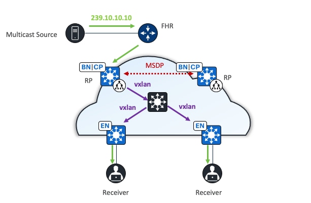
Native multicast
Native multicast does not require the ingress fabric node to do unicast replication. Instead, the whole underlay, including intermediate nodes (nodes not operating in a fabric role) are used to do the replication. To support native multicast, the FHR, last-hop routers, and all network infrastructure between them must be enabled for multicast.
Native multicast uses PIM-SSM for the underlay multicast transport. The overlay multicast messages are tunneled inside underlay multicast messages. This approach allows overlap in the overlay and underlay multicast groups in the network, if required. Because the entire underlay network between source and receiver is working to do the packet replication, scale and performance is significantly improved compared to head-end replication.
Native multicast does multicast-in-multicast encapsulation. Multicast packets from the overlay are encapsulated within multicast packets in the underlay. With this method, both PIM-SSM and PIM-ASM can be used in the overlay.
Native multicast underlay configurations can be achieved through LAN automation ( see Onboard underlay device with LAN automation) or manual configuration (see Configure native multicast).
When the multicast source is outside the fabric site, the border nodes replicate the original multicast packet using the underlay multicast SSM tree. They then encapsulate the packet in VXLAN and send it towards the intermediate node. The intermediate node replicates the original multicast packet and forwards one copy to each edge node where receivers are connected. The edge node decapsulates the VXLAN packet and forwards it to receivers.
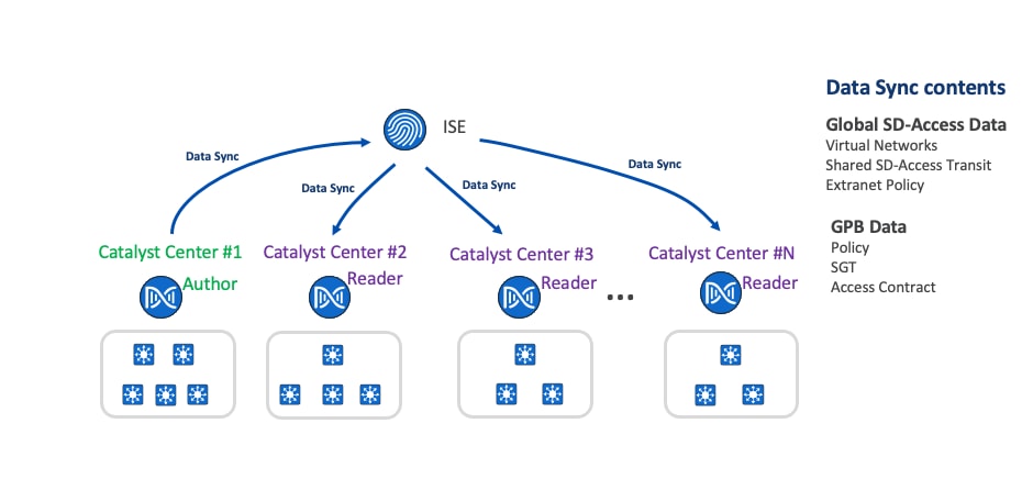
Table 2. Comparison of head-end and native multicast
|
|
Head-end replication |
Native multicast |
| Supported modes (overlay) |
ASM, SSM |
ASM, SSM |
| Supported modes (underlay) |
N/A |
SSM (through LAN automation or manual configuration) |
| RP placement (ASM, overlay) |
Inside or outside the fabric site |
Inside or outside the fabric site |
| Multicast source placement |
Inside or outside the fabric site |
Inside or outside the fabric site |
| RP redundancy (ASM, overlay, inside fabric site) |
MSDP |
MSDP |
| Multicast forwarding |
Multicast packets are encapsulated in VXLAN and forwarded as unicast towards edge node separately |
Multicast packets are encapsulated in VXLAN as multicast and forwarded to edge nodes through underlay multicast tree |
The advantage of head-end replication is that it does not require multicast in the underlay network. This creates a complete decoupling of the virtual and physical networks from a multicast perspective. However, this can create high overhead on the FHRs and result in high bandwidth use. In deployments where multicast cannot be enabled in the underlay networks, head-end replication can be used. Native multicast is recommended for its efficiency and ability to reduce the load on the FHR fabric node.
This guide focuses on native multicast in the Deployment section.
Cisco SD-Access layer 2 flooding
The layer 2 flooding feature enables the flooding of broadcast, link-local multicast, and ARP traffic for a given overlay subnet. In traditional networking, broadcasts are flooded out of all ports in the same VLAN. By default, Cisco SD-Access handles frames without using layer 2 broadcast and unknown unicast flooding, using alternative methods to manage ARP needs and maintain standard IP communication between endpoints.
However, some networks need to use broadcast, particularly to support silent hosts that generally require reception of an ARP broadcast to come out of silence. This is commonly seen in building management systems (BMS) that have endpoints that need to be able to ARP for one other and receive a direct response at layer 2. Another common use case for broadcast frames is wake on LAN (WoL) Ethernet broadcasts, which wake up sleeping hosts in the same broadcast domain.
Layer 2 flooding works by mapping the overlay subnet to a dedicated multicast group in the underlay. Broadcast, link-local multicast, and ARP traffic are encapsulated in fabric VXLAN and sent to the destination underlay multicast group. PIM ASM is used as the transport mechanism.
All fabric edge nodes within a fabric site will have the same overlay VNs and overlay IP subnets configured when a fabric zone is not configured. A fabric zone is recommended to avoid unnecessary layer 2 flooding traffic. The flooding is restricted to selected fabric edges and not the entire fabric. It is also recommended to separate endpoints that require flooding in their own VLANs. When layer 2 flooding is enabled for a given subnet, fabric edge nodes send multicast PIM joins for the respective underlay multicast group, effectively pre-building a multicast shared tree. A shared tree must be rooted at an RP. For layer 2 flooding to work, this RP must be in the underlay. LAN automation can be used to configure the underlays.
If LAN automation is used, the LAN automation primary device (seed device) along with its redundant peer (peer seed device) are configured as the underlay RP on all discovered devices. MSDP is automatically set up between seed devices to establish Anycast RP for layer 2 flooding. Additionally, PIM sparse mode is activated on Loopback0 and all point-to-point interfaces are configured through LAN automation.
If layer 2 flooding is needed and LAN automation is not used to discover all the devices in the fabric site, multicast routing must be enabled manually on the devices in the fabric site, and MSDP should be configured between the RPs in the underlay. Loopback0 can be used as the connect-source and originator-ID for the MSDP peering.
Connect-source uses the primary IP address on the configured interface as the source IP address for the MSDP TCP connection. Originator-ID allows the MSDP speaker, originating a source-active (SA) message, to use the IP address of the defined interface as the RP address of the SA message. Originator-ID is the mechanism by which MSDP works to address the RPF check. If configuring the underlay manually, to echo the same configuration elements done through LAN automation, Loopback60000 can be used as the RP address on the MSDP peers in the underlay.
Multisite remote border
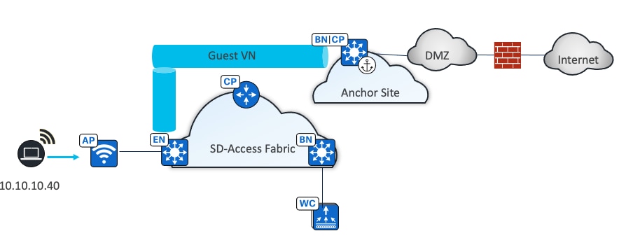
A multisite remote border (MSRB) enables the fabric network to isolate untrusted traffic to a central location like a firewall or a demilitarized zone (DMZ). For example, if the network has a guest VN that is stretched across multiple sites, all the guest traffic can be tunneled to a remote border at the DMZ, thus isolating the guest traffic from the enterprise traffic.
In a multisite network deployment, a network administrator can designate a common border (MSRB) to route the traffic to and from a particular VN that is stretched across multiple sites. This allows an administrator to deploy a VN across multiple fabric sites with a single subnet across all these sites. Preserving the subnets across multiple fabric sites helps to conserve the IP address space.
Some common terms used in the context of an MSRB include:
● Anchored virtual network:
A virtual network that exists across multiple fabric sites in a network. The associated IP subnet and segment are common across these multiple sites.
● Anchor site:
A fabric site that hosts the common border and control plane for an anchor VN. An anchor site handles the ingress and egress traffic for the anchor VN.
● Inherited sites:
The fabric sites other than the anchor site where the anchor VN is deployed.
● Multisite remote border:
The fabric border node at the anchor site that provides the ingress and egress location for traffic to and from the anchor VN.
● Anchor control plane node:
The fabric control plane node at the anchor site that accepts registrations and responds to requests for endpoints in the anchor VN.
Multiple Catalyst Center to single Cisco ISE
Cisco ISE scales to 2,000,000 endpoints. Catalyst Center scales between only 25,000 to 100,000 endpoints (25,000 for DN3-HW-APL 32-core appliance, 40,000 for DH3-HW-APL-L 56-core appliances, and 100,000 for DN3-HW-APL-XL 112-core appliances). The multiple Catalyst Center functionality allows multiple Catalyst Centers to integrate with the same Cisco ISE for customers who have large or distributed enterprise fabric deployments. Using the concepts of author node and reader nodes, this feature creates a single management point for policy definitions and global Cisco SD-Access data in the deployment. Replication of these definitions is then propagated from author node to the read nodes through Cisco ISE.
Solution design
The multiple Catalyst Center feature uses the existing secure connection with Cisco ISE to replicate VNs, SGTs, access contracts, policies, shared Cisco SD-Access transit and extranet policies, from one cluster to another cluster that are integrated with the same Cisco ISE deployment. Cisco ISE takes the information learned from one cluster (author node) and propagates it to the other clusters (reader nodes)
Author node
Author node is the first Catalyst Center that integrates with Cisco ISE. It pushes global Cisco SD-Access and GPB data to Cisco ISE using ERS with pxGrid REST API interfaces. Creation, modification, or deletion of GPB and Cisco SD-Access components can only be done on the author node. All the changes made to the author node are synchronized to Cisco ISE and then Cisco ISE publishes to the reader nodes.
Only one Catalyst Center can be designated as the author node. It is the only node that can be brownfield (containing a user defined VN, shared Cisco SD-Access transit, extranet policy, SGTs, access contracts and Group-Based Access Control [GBAC] policy).
Reader node
All other Catalyst Centers integrated with the same Cisco ISE reader nodes. Reader nodes have a read-only view of security groups and global Cisco SD-Access data, but they have no access contracts or policies visibility. Instead, the reader nodes have a hyperlink to cross-start to the author node to access the information.
Reader nodes use the same SGTs, access contracts, GBAC policy, global Cisco SD-Access data defined on the author node cluster. These objects are available to use for provisioning operations just as if this were a stand-alone Catalyst Center.
Up to four reader nodes are supported and any reader node can be promoted to assume author role. A Catalyst Center must have no user-defined VNs before adding it as a reader node.
Note: This is a limited availability feature. Contact the Cisco SD-Access Design Council to participate in the Limited Availability program, if interested.
Cisco SD-Access wireless
Cisco SD-Access provides a unique differentiator by integrating the wireless control plane with the overlay control plane of the wired world. Cisco SD-Access wireless offers a centralized control and management plane with a distributed data plane providing both centralized and distributed wireless designs. The wireless controller integrates with the control plane node. It registers endpoints as they are onboarded and updates their location as they roam. This is the first instance where there is synergy between the wireless and wired control planes.
This unique integration of wired and wireless brings several benefits to network users and the operations team that support them:
● Simplification:
Networks can have a single subnet for both wired and wireless clients.
● Consistency of policy:
The extensive set of wired policies are extended to wireless traffic, and they are both applied at the edge node.
● Improved performance:
Wireless roaming is layer 2 and does not require anchoring.
Integration modes
Cisco SD-Access supports several options for integrating wireless access into the network.
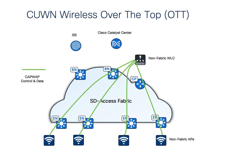
One option is to use traditional Cisco Unified Wireless Network (CUWN) local-mode configurations over-the-top as a non-native service. In this mode, the Cisco SD-Access fabric is a transport network for the wireless traffic, which can be useful during migrations to transport tunneled Control and Provisioning of Wireless Access Points Protocol (CAPWAP) endpoint traffic from the APs to the wireless controllers.
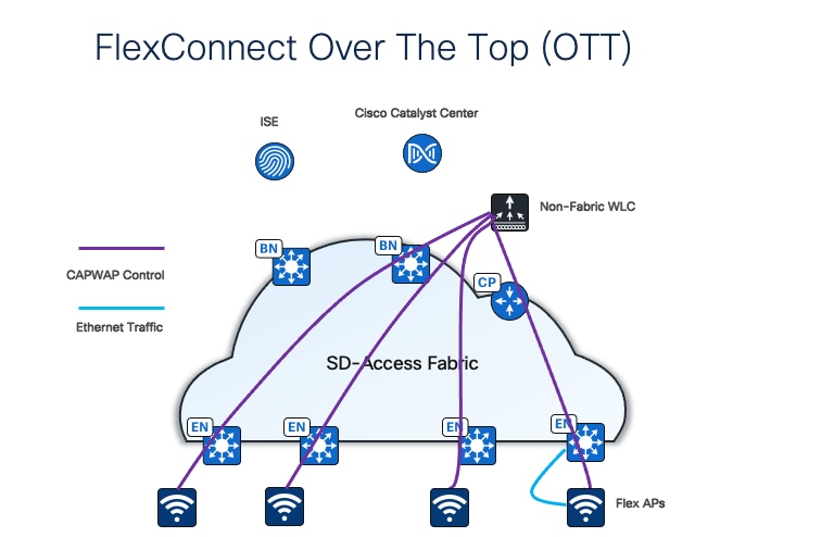
A second option is FlexConnect over-the-top (OTT). In this mode, APs redirect traffic locally to the edge nodes to which they are connected.
Note: To achieve faster roaming latency, the additional Cisco SD-Access feature Intra-Subnet Routing, which disables layer 2 flooding, must be configured. If layer 2 flooding is required, flex OTT integration with Cisco SD-Access may not be supported by all flex Wi-Fi vendors.
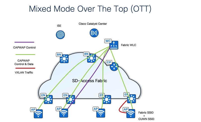
A third option is mixed mode, where the fabric wireless controller broadcasts both fabric and nonfabric (centralized) SSIDs. Mixed mode is supported both on the same AP or different APs. Traffic from clients who join nonfabric SSID is encapsulated in CAPWAP and sent to the wireless controller. Fabric client-traffic is VXLAN encapsulated and sent to the fabric ed
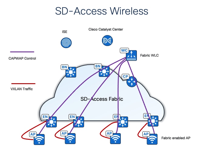
The last and the best option is fully integrated Cisco SD-Access Wireless, extending the Cisco SD-Access beyond wired endpoints to also include wireless endpoints.
Integrating the wireless LAN into the fabric provides the same advantages for the wireless clients as provided to the wired clients in the fabric, including addressing simplification, mobility with stretched subnets, and end-to-end segmentation with policy consistency across the wired and wireless domains. Wireless integration also enables the wireless controller to shed data plane forwarding duties while continuing to function as the control plane for the wireless domain.
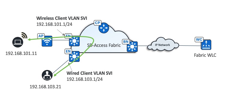
Fabric wireless controllers manage and control the fabric-mode APs using the same general model as the traditional local-mode controllers which offers the same operational advantages such as mobility control and radio resource management. A significant difference is that client traffic from wireless endpoints is not tunneled from the APs to the wireless controller. Instead, communication from wireless clients is encapsulated in VXLAN by the fabric APs which build a tunnel to their first-hop fabric edge node. Wireless traffic is tunneled to the edge nodes as the edge nodes provide fabric services such as the layer 3 anycast gateway, policy, and traffic enforcement.
This difference enables a distributed data plane with integrated SGT capabilities. Traffic forwarding takes the optimum path through the Cisco SD-Access fabric to the destination while keeping consistent policy, regardless of wired or wireless endpoint connectivity.
The control plane communication for the APs uses a CAPWAP tunnel to the wireless controller, which is similar to the traditional CUWN control plane. However, a fabric wireless controller is integrated into the Cisco SD-Access control plane (LISP) communication. When added as a fabric wireless controller, the controller builds a two-way communication to the fabric control plane nodes.
This communication allows the wireless controllers to register client layer 2 MAC addresses, SGT, and layer 2 segmentation information (layer 2 VNI). All this works together to support wireless client roaming between APs across the fabric site. The Cisco SD-Access fabric control plane process inherently supports the roaming feature by updating its host-tracking database when an endpoint is associated with a new RLOC (wireless endpoint roams between APs).
This deployment guide focuses on fully integrated Cisco SD-Access wireless.
Cisco SD-Access wireless platform support
Cisco SD-Access wireless is supported on variety of Cisco wireless controller platforms and APs, for instance:
● Cisco 3504,5520 and 8540 Series Wireless Controllers
● Cisco Catalyst 9800 Series Wireless Controllers
● Embedded wireless controller on Cisco Catalyst 9300/9400/9500
● Wi-Fi 6 APs: Cisco Catalyst 9105AX,9115AX,9117AX,9120AX,9124AX, and 9130AX Series
● Wi-Fi 6 APs: Cisco Catalyst 9163E,9164, and 9166 Series
● Cisco Catalyst Wireless 9162I Unified Access Points
● 802.11 Wave 2 APs: Cisco Aironet 1800, 2800,3800, and 4800 Series
● 802.11 Wave 2 outdoor APs: Cisco Aironet 1540, 1560
● Heavy Duty Series APs: Cisco Catalyst IW6300, IW9165, and IW9167
● Cisco Industrial Wireless 3702 Access Points
See the Cisco SD-Access Compatibility Matrix for the latest supported device model and software information.
Cisco SD-Access wireless deployment consideration
This section gives some important considerations for deploying wireless controller and APs in a Cisco SD‑Access wireless network.
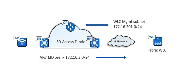
Wireless controller
● The wireless controller is located outside of the fabric.
● The fabric AP is local to the fabric and joins the wireless controller in local mode.
● The border advertises the wireless controller management subnet to the fabric.
● The border advertises fabric prefixes to the wireless controller management network.
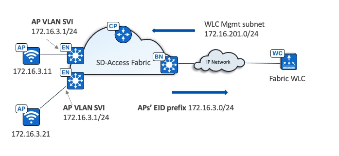
APs
● APs are directly connected to the fabric edge or extended node devices.
● APs are in overlay space on fabric edges.
● APs get registered in the control plane database.
● Simplify IP design for AP onboarding, one subnet for each fabric site for AP onboarding.
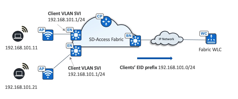
Clients flow
● Client subnets are distributed on fabric edge switches.
● Client subnets on wireless controllers do not need defining.
● Client subnets are mapped to VLAN with an anycast gateway on all fabric edge switches.
● All roams are layer 2.
Wireless traffic flow
● Wireless client traffic is distributed
● No hair-pinning to centralized controller
● Communication to wired clients goes directly through the fabric
In summary:
APs must be deployed accordingly:
● Connect directly to the fabric edge (or to an extended node switch)
● Be a part of the fabric overlay
● Belong to the INFRA_VN, which is mapped to the global routing table
● Join the wireless controller in Local mode
Wireless controllers must be deployed accordingly:
● Reside in the global routing table
● Connect as standalone wireless controllers outside the fabric (optionally directly to border)
● Belong to one fabric site
● Consider limitations, such as an embedded wireless controller on a Cisco Catalyst 9300/9400/9500, which has limitations in scale and feature support, therefore, it is only recommended for small branch deployments
● Avoid using Cisco 3504,5520, and 8540 Series wireless controllers in a new deployment because they will be phase out in the near future
Note: Wireless controllers should not be reachable through the default route. Use a specific route in the global routing table for each fabric node.
Wireless controller redundancy
Wireless controllers support high availability (HA) using both SSO (stateful) and N+1 (stateless) architectures for the fabric-aware controller.
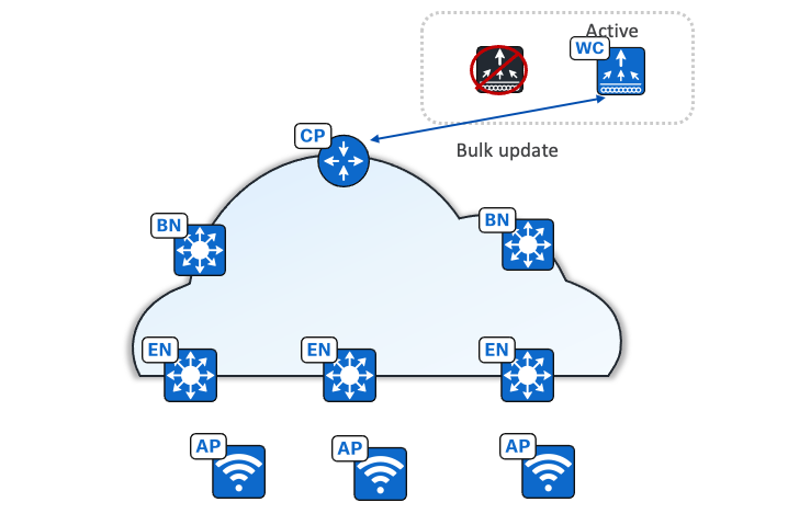
In stateful redundancy with SSO architecture, the wireless controller pair is seen as one node by the fabric. Only the active wireless controller interacts with fabric control plane nodes. The fabric configuration and control plane status are synchronized between the active and standby wireless controller. If there is a failure, a new active wireless controller bulk updates fabric clients to a fabric control plane node (host tracking database node) so that APs and clients stay connected.
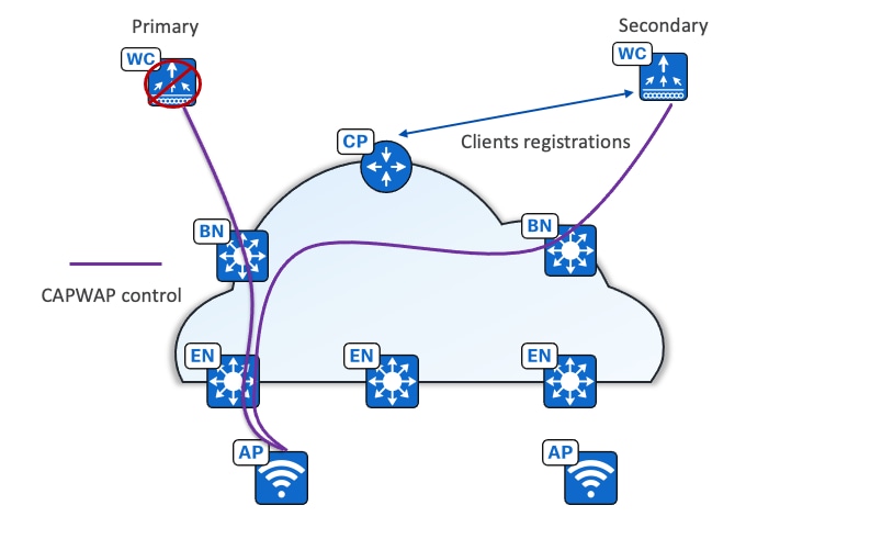
With the stateless N+1 redundancy architecture, APs are configured with primary and secondary wireless controllers. APs and associated wireless controllers register with the primary wireless controllers. Upon primary failure, the AP disconnects and joins the secondary wireless controller. Wireless clients are also disconnected and join the secondary. The secondary performs new client registration in the fabric control plane node (host tracking).
Cisco SD-Access Wireless Guest Access Design
In a fully integrated Cisco SD-Access wireless network, wireless guest access can be integrated using different solutions:
● A dedicated guest VN
● A dedicated guest fabric site (MSRB VN anchoring solution)
● An OTT solution leveraging a guest anchor controller
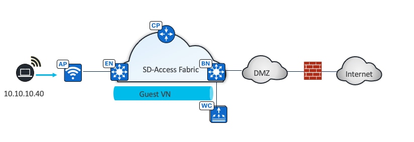
In this design, the guest network is established as a separate VN within the Cisco SD-Access fabric, using macrosegmentation to isolate the guest data plane from other enterprise traffic. Configuration is done through Catalyst Center by creating a VN, defining IP pools, and associating the SSID with the guest IP pool. Microsegmentation can be used as a second layer segmentation in the VN. Different SGTs can be assigned for different guest roles.
The same guest VN can also be used for wired guest clients.
Guest as a separate fabric site (MSRB VN anchoring solution)
If complete isolation is required for the guest network, for the data plane traffic and the control plane, you can configure a dedicated control plane and border (MSRB) with an anchor VN and an anchor pool in Catalyst Center to manage guest users.
In this solution the traffic is encapsulated at the AP in the VXLAN to the fabric edge switch, but the fabric edge node is configured to use a different border node for the anchor VN. This border node can reside in another fabric site, providing complete traffic isolation. The guest users register in a dedicated control plane that may be colocated with the border, and the users get an IP address in the DMZ.
Like the dedicated VN solution, this design provides policy consistency for wired and wireless guests. The choice of a guest control plane and border depend on the scalability of the solution.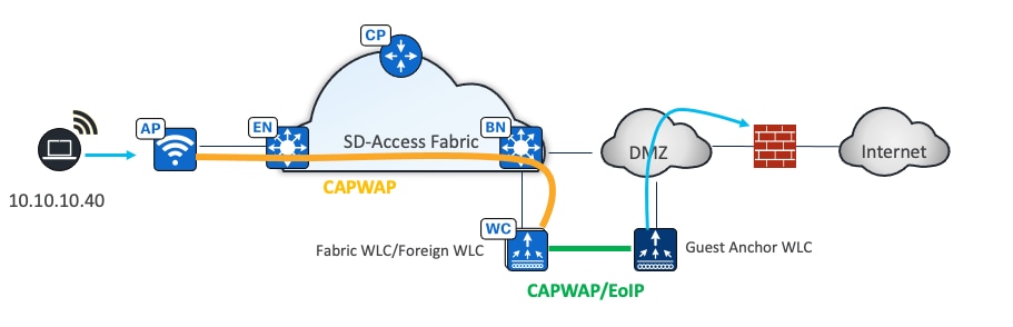
OTT Solution leveraging Cisco Unified Network Guest Anchor
Use guest anchor controllers by deploying the guest wireless network as an OTT solution. The WLAN for guests can be configured to be anchored at a guest anchor controller in the DMZ, and the traffic will be an overlay to the fabric. This well proven Cisco Unified Wireless Network solution protects the customer investment and is particularly suited for brownfield deployments.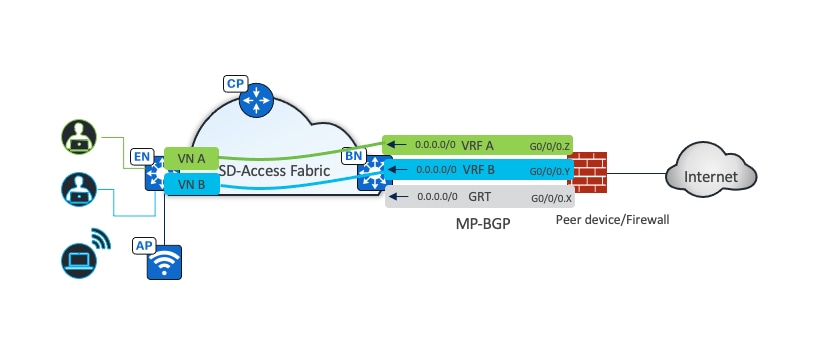
Cisco SD-Access network deployment considerations
Underlay network design
Having a well-designed underlay network ensures the stability, performance, and efficient use of the Cisco SD-Access network. Automation for deploying the underlay network is available through Catalyst Center using the LAN automation capability.
Whether using LAN automation or deploying the network manually, the underlay networks for the fabric have these general design requirements:
● MTU and TCP MSS:
The VXLAN header adds 50 bytes of encapsulation overhead. Enabling a campus and branch-wide MTU of 9100 ensures that Ethernet jumbo-frames can be transported without fragmentation inside the fabric.
There are scenarios where the underlay network does not support more than 1500-byte packets, for example, if the fabric sites are connected using a Cisco SD-Access transit over a WAN that does not support more than 1500-byte packets. In these scenarios, the Transmission Control Protocol Maximum Segment Size (TCP MSS) can be set to limit the packet size, considering the overhead from VXLAN header encapsulation. The recommended value is 1250. Catalyst Center supports TCP MSS automation. This method works only on TCP applications.
MTU 9100 configuration is supported by LAN automation on all Catalyst 9000 switches.
● Point-to-point links:
Point-to-point links provide the quickest convergence times because they eliminate the wait for the upper layer protocol timeouts typical of more complex topologies. Combining point-to-point links with the recommended physical topology design provides fast convergence if a link fails.
Point-to-point configuration is supported by LAN automation on all Catalyst 9000 switches.
● ECMP:
Equal-cost multipath routing is a routing strategy where next-hop packet forwarding to a single destination can occur over multiple best paths. Load balancing between these ECMP paths is performed automatically using Cisco Express Forwarding (CEF). ECMP-aware routing protocols should be used to leverage parallel-cost links and ensure redundant forwarding paths for enhanced resiliency.
● BFD:
Bidirectional forwarding detection enhances fault detection and convergence characteristics of routing protocols. Routing protocols use the absence of Hello packets to determine if an adjacent neighbor is down (commonly called Hold Timer or Dead Timer). Thus, the ability to detect liveliness in a neighbor is based on the frequency of Hello packets. BFD provides low overhead, subsecond detection of failures in the forwarding path between devices and can be set as a uniform rate across a network using different routing protocols that may have variable Hello timers.
BFD is configured through LAN automation on all LAN automated layer 3 interfaces with (rx_min 250ms, tx_min 250 ms) x 3.
● NSF:
Non-stop forwarding, or graceful restart, works with SSO to provide continued forwarding of packets during a route processor (RP) switchover. NSF-aware IGP routing protocols should be used to minimize the amount of time that a network is unavailable following a switchover.
● SSO:
Stateful switchover maintains stateful feature information, such as user session, by synchronizing state information between a primary and backup route processor such as an RPs in routing platforms or supervisor engines in switching platforms. SSO should be enabled together with NSF on supported devices.
● IGP process for the fabric:
While IS-IS is currently the only supported protocol for LAN automation, other classless routing protocols such as OSPF and EIGRP are supported and are both ECMP and NSF-aware.
● Loopback0 propagation:
Catalyst Center uses Loopback0 interfaces as the RLOCs in LISP configurations and they require a /32 mask. Reachability between loopback addresses (RLOCs) cannot use the default route, they must use an explicit route (/32 route) inside the fabric site.
In a multisite Cisco SD-Access transit deployment, Loopback 0 addresses of an external border and a transit control plane node need to be advertised. In an MSRB deployment, MSRB and the fabric edges in an anchored site also must have a /32 route to each other.
LAN automation configures Loopback0 with the /32 subnet from a provided LAN pool.
● Wireless controller reachability:
Connectivity to the wireless controller should be treated as reachability to the loopback addresses. A default route in the underlay cannot be used for fabric edges to reach the wireless controllers. A specific route (non-default route) to the wireless controller IP address must exist in the GRT (underlay) at each fabric edge where the APs are physically connected. This can be a host route (/32) or a summarized route.
● LAN automation for deployment:
The configuration of the underlay can be orchestrated by using LAN automation services in Catalyst Center. LAN automation is an alternative to manual underlay deployments for new networks. It uses an IS-IS routed access design. The IS-IS routing protocol offers operational advantages such as neighbor establishment without IP protocol dependencies, peering capability using loopback addresses, and agnostic treatment of IPv4, IPv6, and non-IP traffic. Manual underlays are also supported, offering flexibility to deviate from an automated underlay deployment, such as selecting a different IGP, while still adhering to the fundamental underlay design principles.
LAN automation is not supported on router platforms and only supported for IPV4 addressing. It can discover and automate up to five tiers of PnP agent devices.
Peer device and shared services routing
As discussed in the Shared services section, shared services are normally outside the fabric site and are the required elements for clients in a Cisco SD-Access network. In a Cisco SD-Access deployment, the peer device is responsible for advertising shared services from an external domain into the fabric. A peer device is outside the fabric and can be either a true routing platform, a layer 3 switching platform, or a firewall that must meet several technological requirements, including:
● Multiple VRFs:
Multiple VRFs are needed for the VRF-aware peer model. For each VN that is handed off on the border node, a corresponding VN and interface is configured on the peer device. The selected platform should support the number of VNs used in the fabric site that will require access to shared services.
● Subinterfaces (routers or firewall):
A virtual layer 3 interface that is associated with a VLAN ID on a routed physical interface. It extends IP routing capabilities to support VLAN configurations using the IEEE 802.1Q encapsulation.
● Switched Virtual Interfaces (layer 3 switch):
Represents a logical layer 3 interface on a switch. This SVI is a layer 3 interface forwarding for a layer 3 IEEE 802.1Q VLAN.
● IEEE 802.1Q:
An internal tagging mechanism that inserts a 4-byte tag field in the original Ethernet frame between the Source Address and Type/Length fields. Devices that support SVIs and subinterfaces also support 802.1Q tagging.
Catalyst Center can automate the configuration on the border nodes with the layer 3 handoff feature. This feature provisions VRF lite by associating each SVI in switching platforms or subinterface in router platforms with a different fabric VN (VRF in the example). An external BGP (eBGP) is used as the routing protocol to advertise the endpoint space (EID-space) prefixes from the fabric site to the external routing domain and to attract traffic back to the EID-space. This BGP peering is also used to advertise routes into the overlay such as for access to shared services on internal border.
As shown in Figure 12, VNs in the fabric site are mapped to VRFs on the firewall to provide routing separation. The eBGP peers are established for each VRF based with border layer 3 handoff to facilitate the separation and routing. The internet service default route 0.0.0.0./0 is advertised to the fabric border node in each VRF.
Depending on how the shared services are deployed, the primary way that shared service routing on peer devices is achieved include:
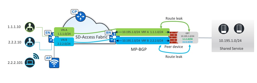
● Route leaking:
Used when shared services routes are located in the Global Routing Table (GRT), IP prefix lists are used on the peer device to identify these routes. Route maps reference these IP prefix lists, and the VRF configurations refer to the route maps to ensure that only the specifically matched routes are leaked.
As shown in Figure 13, eBGP peers are established for each VRF based with border layer 3 handoff. The shared service prefix is in the GRT. Route leaking is performed on the peer device, where client prefixes from VRFs are leaked to the GRT. Shared service prefixes in the GRT are leaked to the VRFs.
● VRF leaking:
Used when shared services are deployed in a dedicated VRF on the peer device. Route-targets under the VRF configuration are used to leak between the fabric VNs and the shared services VRF.
Macrosegmentation uses VNs to isolate clients. Clients in different VNs cannot communicate with each other.
Microsegmentation uses SGT and Security Group Access Control Lists (SGACL) to enforce traffic policies at the egress access device.
● Classification:
Clients are coming online in the same VN and assigned different SGTs: SGT 21 (Teachers), SGT 22 (Students) and SGT 26 (Admin). The SGT assignment can be achieved through Cisco ISE using authentication and authorization rules or statically assigned based on the connected port or IP address pools (configurable from Catalyst Center). SGACL rules are downloaded from the Cisco ISE to the fabric edge where the client Admin is connected.
● Propagation:
Within the same fabric site but across different fabric edges, or between different fabric sites connected through Cisco SD-Access transit, the source SGT is encapsulated within the VXLAN header. The traffic is then forwarded to the fabric edge where the client Admin is connected.
● Enforcement:
Happens on the fabric edge where the client Admin is connected. Based on the SGACL, traffic from client Teacher is allowed, but traffic from client Student is denied and dropped.
If clients are connected to the same fabric edge, propagation is not needed. Enforcement happens directly on this fabric edge.
For fabric wireless clients, the wireless controller sends the SGT to the AP when a client joins through Cisco ISE using authentication and authorization or statically assigned to the SSID (configurable from Catalyst Center). The AP puts this SGT in the VXLAN header when it forwards data traffic from the wireless client to the ingress fabric edge over the VXLAN tunnel. At egress, fabric edge policy enforcement happens. For clients connected to the same AP and on the same VLAN, the traffic flow is always switched at the fabric edge. The AP encapsulates the traffic within a VXLAN tunnel directed to the fabric edge, which then handles the switching of the traffic back to the same AP.
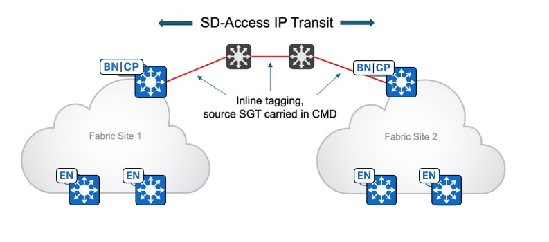
Because a VXLAN data plane carries SGT natively, microsegmentation can be used directly within the same fabric site or multiple fabric sites with Cisco SD-Access transit. With IP-based transit, due to the de‑encapsulation of the fabric packet, SGT policy information can be lost. Inline tagging and SXP can carry SGT information between two fabric sites connected using IP transit.
Inline tagging
Inline tagging is the process where the SGT is carried out within a special field known as Cisco Meta Data (CMD) that can be inserted in the header of the Ethernet frame. This changes the Ether Type of the frame to 0x8909. If the next-hop device does not understand this Ether Type, the frame is assumed to be malformed and is discarded. Ways to propagate SGTs end-to-end inline tagging include:
● Hop-by-hop:
Each device in the end-to-end chain would need to support inline tagging and propagate the SGT.
● Preserved in tunnels:
SGTs can be preserved in the CMD inside of the Generic Routing Encapsulation (GRE) tunneling protocol or in the CMD inside of the IPsec tunnel encapsulation.
With inline tagging, the SGT is embedded into the Ethernet frame. The ability to embed the SGT within an Ethernet frame requires specific hardware support. Network devices without the hardware support can use SXP.
SXP over TCP
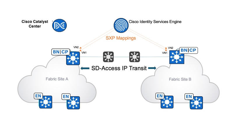
SXP is used to distribute SGTs to border nodes across an interconnecting network that does not support carrying the SGT in the data plane. This allows the borders to reclassify the incoming IP packet and insert the SGT into the VXLAN data plane as the packet is forwarded to the fabric edge towards the destination endpoint.
When users and endpoints authenticate and are authorized into the network, Cisco ISE assigns the SGT using the authorization table and learns the user and endpoint IP address using accounting. Cisco ISE creates the association of an IP-SGT mapping of that user and endpoint and sends it to another fabric site when Cisco ISE has SXP connections with devices in other sites.
For example, as shown in Figure 16, mappings created from Site A are sent to Site B using SXP. This mapping allows traffic flowing from Site A to Site B to be classified on the Site B border with the original source SGT and then carries over VXLAN and enforces it on the fabric edge.
Inline tagging compared with SXP
The SGT-propagation method use depends on the platforms in the path. Not all devices are capable of inline tagging. But if the devices support both inline tagging and SXP, inline tagging is preferred.
Inline tagging occurs within the data plane without impacting performance. SXP is a control plane function that impacts CPU and memory performance.
SXP scalability is another consideration. The number of SXP peers and the number of IP-SGT mappings in different platforms can be found in the policy platform capability matrix.
Firewall as peer device
A firewall is used as a security measure that monitors and controls incoming and outgoing network traffic based on predetermined security rules in a traditional network. It acts as a barrier between a trusted internal network and untrusted external networks, such as the internet.
In fabric deployment, a firewall can be used as a peer device that is connected to fabric border devices to provide access to shared services and the internet, segment guest networks from internal networks, or for interVN communications.
Provide access to shared services/internet
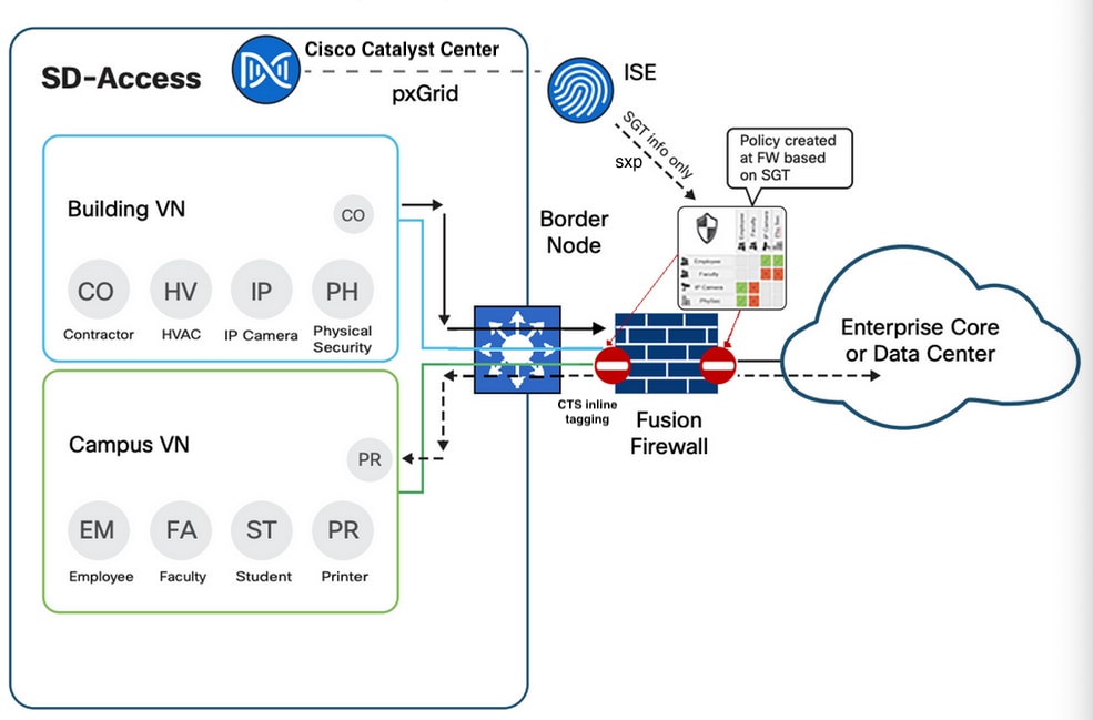
A firewall is connected to both fabric border and data center. Shared service prefixes are advertised to a firewall from a data center. BGP peers are configured between a fabric border (through layer 3 handoff) and a firewall (manual configuration) so that the shared service prefixes can be advertised from the firewall to the border in each VN (Building and Campus, as shown in Figure 17). Client prefixes from these two VNs are advertised to the firewall. The firewall can use a single VRF solution or a multiVRF solution. In case of multiVRF, shared service prefixes are in a dedicated VRF, such as global. The routes leaking is required between Building and global, and Campus and global, so shared service prefixes are leaked to Building and Campus, and client prefixes are leaked to global.
Similarly for internet access, the firewall advertises a default route to the borders in each VN (Building and Campus). Client prefixes are leaked in global when a multiVRF solution is in use.
InterVN communication
In most deployments, endpoints, users, or devices that need to directly communicate with each other should be placed in the same VN. But some networks may have specific requirements for VN-to-VN communication. VN-to-VN requirements are often seen during mergers of companies or in some corporate or government structures or similar multitenant environment where each agency, tenant, or division is required to have their own VN-space. As shown in Figure 17, the firewall can advertise the default route to a border device in the Campus and Building VN. Since it has reachability information about the client prefixes in each VN, traffic between Campus and Building can be routed through the firewall.
Policy enforcement
A firewall is a policy-oriented device and can be configured to use SGT in the rules for traffic enforcement. In the figure, the firewall receives SGT information from Cisco ISE through SXP (SGT exchange protocol over TCP) and receives traffic with SGT information in Ethernet CMD from the border through inline tagging. However, unlike fabric devices, the SGT based rules and policies are not downloaded from Cisco ISE. They are configured manually in the firewall. With policy enforcement, InterVN communications can be restricted only among specific clients.
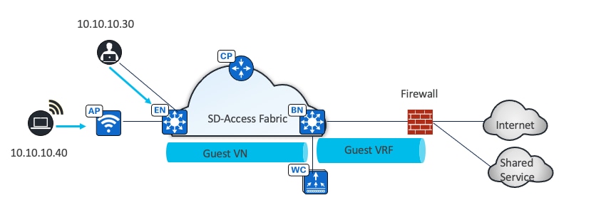
As shown in Figure 18, in a guest network, a firewall can be used to ensure that visitors have only limited access to sensitive resources. Guest traffic is separated from enterprise traffic and located in a dedicated guest VN.
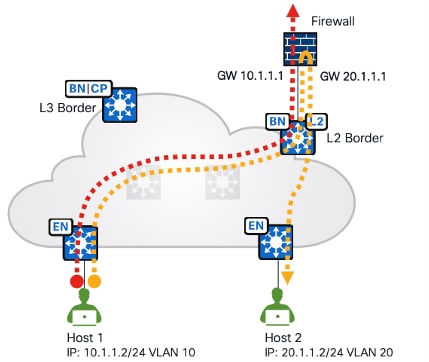
As shown in Figure 19, another deployment scenario is with a layer 2 border where the gateway is configured on the firewall and located outside the fabric. The firewall as the gateway can inspect interVLAN traffic and traffic exiting the fabric.
Cisco ASA and Cisco Firepower Threat Defense (FTD) are recommended. They can be managed by Catalyst Center with limited support (polices, routings and so on are not supported) and integrate with Cisco ISE. They can provide stateful inspection for interVN communication and provide Intrusion Prevent System (IPS) capabilities, advanced malware protection (AMP), granular Application Visibility and Control (AVC), and URL filtering. They also have a detailed reporting capability with information about traffic sources, destinations, usernames, groups, and firewall actions with guaranteed logging of permits and drops.
They can be deployed as a cluster (multiple devices acting as a single logical unit), as an HA pair (commonly Active and Standby), or even as a standalone device.
For a full list of supported firewall platforms, see the Catalyst Center Compatibility Matrix.
Fabric site sizes – design strategy
A practical goal for Cisco SD-Access designs is to create larger fabric sites rather than multiple, smaller fabric sites. The design strategy is to maximize fabric site size while minimizing total site count. Some business requirements necessitate splitting locations into multiple sites, such as creating a fabric site for an Emergency Room (ER) that is separate from the fabric site that is represented by the remainder of the hospital.
The multidimensional factors of survivability, HA, number of endpoints, services, and geography are all factors that drive the requirement for multiple, smaller fabric sites instead of a single large site. To help with designing fabric sites of varying sizes, reference models were created, including:
● Fabric-in-a-Box (FiaB) site
● Small site
● Medium site
● Large site
● Extra-large site
Each fabric site includes a supporting set of control plane nodes, edge nodes, border nodes and wireless controllers, sized appropriately from the listed categories. Cisco ISE PSN are also distributed across the sites to meet survivability requirements.
FiaB site
The FiaB Site Reference Model should target less than 200 endpoints. The central component of this design is a switch stack or StackWise Virtual operating in all three fabric roles: control plane node, border node, and edge node. For switch stack FiaB deployments, Cisco SD-Access EWC on Catalyst 9000 is used to provide site-local wireless controller functionality. The site may contain an Cisco ISE PSN depending on the WAN and internet circuit and latency.
For similar site design sizes, stay within the table guidelines. The numbers are used as guidelines and do not necessarily match specific limits for devices used in the design of this site size.
Table 3. Fabric-in-a-Box Site Reference Model guidelines
| Component |
Number |
| Endpoints, target fewer than |
200 |
| Virtual networks, target fewer than |
5 |
| IP pools, target fewer than |
8 |
| APs, target fewer than |
40 |
HA in this design is provided through switch stacking or StackWise Virtual, which both combine multiple physical switches into a single logical switch. StackPower is used to provide power redundancy between members in a switch stack. StackWise Virtual deployments have power redundancy by using dual power supplies in each switch. If a chassis-based switch is used, HA is provided through redundant supervisors and redundant power supplies. To support power redundancy, available power supplies need to be redundant beyond the requirements of the switch to support power, chassis, supervisor, and line cards.
Tech tip: Client SSO provides the seamless transition of clients from the active controller to the standby controller. Client information is synchronized from the active to the standby to avoid client reassociation during a switchover event.
wireless controllers can be deployed as physical units directly connected to the fabric-in-a-box or deployed as the embedded Catalyst 9800 controller. When using the embedded Catalyst 9800 with a switch stack or redundant supervisor, AP and Client SSO are provided automatically. StackWise Virtual deployments of fabric-in-a-box need physical wireless controllers.
When using stacks, links to the upstream routing infrastructure should be from different stack members. Ideally, the uplinks should be from the member switches rather than the active stack. With chassis switches, links should be connected through different supervisors. To prepare for border node handoff automation along with having initial IP reachability, SVIs and trunk links are commonly deployed between the small site switches and the upstream routing infrastructure.
Small site
The Small Site Reference Model supports fewer than 2,000 endpoints. The physical network is usually a two-tier collapsed core or distribution layer with an access layer servicing several wiring closets. Rather than colocating all roles in one device, the small site model provides added resiliency and redundancy along with a larger number of endpoints by separating the edge node roles onto dedicated devices in the access layer. The border and control plane nodes are colocated in the collapsed core layer. For Cisco SD‑Access wireless, the embedded wireless controller is provisioned on one of the colocated border and control plane nodes. Optionally, a virtual or hardware-based wireless controller is used. If there are fewer than 200 APs and 4,000 clients, Cisco SD-Access embedded wireless can be deployed along with the colocated border node and control plane node functions on a collapsed core switch. Use hardware or a virtual wireless controller for wireless HA.
For similar site design sizes, stay within the table guidelines. The numbers are used as guidelines and do not necessarily match specific limits for devices used in the design of this site size.
Table 4. Small Site Reference Model guidelines
| Component |
Number |
| Endpoints, target fewer than |
2,000 |
| Virtual networks, target fewer than |
8 |
| IP pools, target fewer than |
20 |
| APs, target fewer than |
100 |
| Control plane nodes, collocated |
2 |
| Border nodes, collocated |
2 |
| Fabric nodes, target fewer than |
50 |
Medium site
The Medium Site Reference Model is designed for a building with multiple wiring closets, using a two-tier network structure that combines core and distribution layers with an access layer.
The medium site supports fewer than 25,000 endpoints and fewer than 2,000 APs. The border node function is colocated with the control plane node function on one or two devices. Ideally, for a HA configuration, deploy a highly resilient single device and a separate wireless controller.
For similar site design sizes, stay within the table guidelines. The numbers are used as guidelines and do not necessarily match specific limits for devices used in the design of this site size.
Table 5. Medium Site Reference Model guidelines
| Component |
Number |
| Endpoints, target fewer than |
25,000 |
| Virtual networks, target fewer than |
50 |
| IP pools, target fewer than |
200 |
| APs, target fewer than |
2,000 |
| Control plane nodes, collocated |
2 |
| Border nodes, collocated |
2 |
| Fabric nodes, target fewer than |
450 |
Large site
The Large Site Reference Model is designed for multiple buildings or a building with multiple wiring closets. The physical network is usually three-tier with core, distribution, and access layers. It may even have a routed super core that aggregates many buildings and serves as the network egress point to the WAN and internet. The border node and control plane node functions are provisioned on separate devices rather than colocating.
The large site supports up to 100,000 endpoints and 6000 APs. The border is distributed using redundant devices from the control plane function, and a separate wireless controller in an HA configuration.
Use the table below to understand the guidelines to stay within for similar site design sizes. The numbers are used as guidelines only and do not necessarily match specific limits for devices used in the design of this site size.
Table 6. Large Site Reference Model guidelines
| Component |
Number |
| Endpoints, target fewer than |
100,000 |
| Virtual networks, target fewer than |
64 |
| IP pools, target fewer than |
450 |
| APs, target fewer than |
6,000 |
| Control plane nodes |
2 - 4 |
| Border nodes (2 as internal, 2 as external) |
2 - 4 |
| Fabric nodes, target fewer than |
750 |
Extra-large site
The Extra-Large Site Reference Model is designed for a building with multiple wiring closets or multiple facilities stretched across a large campus. The physical network is a three-tier network with core, distribution, and access layers and may sometimes have a super core in a four-tier. An extra-large network requires dedicated services exit points such as a dedicated data center, shared services block and internet services.
The extra-large site supports up to 20,0000 endpoints and 10,000 APs. Multiple border nodes are distributed from the control plane node function on redundant devices, and sperate wireless controllers in an HA configuration.
Ecosystem
Catalyst Center has an ecosystem with a variety of parallel solutions and third-party applications. This section describes those ecosystem solutions in the context of Cisco SD-Access.
Wide Area Bonjour
Bonjour is a zero-configuration solution that simplifies network configuration and enables communications between connected devices, services and applications. Bonjour is designed for single layer 2 domains such as small, flat networks.
The Cisco Wide Area Bonjour applications on Catalyst Center eliminate the single layer 2 domain constraint and expand the scope to larger layer 3 domains that are used in Cisco SD-Access wired and wireless networks.
ThousandEyes
The ThousandEyes application is hosted on Catalyst 9000 Series switches and is provisioned through a workflow in Catalyst Center. ThousandEyes provides a way to monitor and observe devices and applications in the network.
A ThousandEyes agent on fabric edge nodes provides network and application visibility from client subnet to services. It also provides network and application visibility from border node to services outside of the fabric site.
Cisco AI Endpoint Analytics
Cisco AI Endpoint Analytics is a solution that detects and classifies endpoint and IoT devices into different categories based on endpoint type, hardware model, manufacturer and operating system type. The Cisco AI Endpoint Analytics engine and user interface runs on Catalyst Center and assigns labels to endpoints by receiving telemetry from the network infrastructure.
Return material authorization workflow
Catalyst Center return material authorization (RMA) workflow makes replacing devices a zero-touch process. A customer flags a failed device in Catalyst Center. They physically install the new device and run the basic zero-touch workflow to bring up the device through the PnP process. Using this process, Catalyst Center automates software image upgrades, installs appropriate licenses and certificates, and applies the basic configurations. When a device is detected by Catalyst Center, it configures the replacement device with the old device configuration. Catalyst Center supports RMA for both fabric and nonfabric devices.
The RMA workflow is demonstrated in the RMA workflow section.
Fabric Assurance
Cisco SD-Access Assurance provides visibility into the Underlay and Overlay, and it enables reachability into critical network services in the Fabric infrastructure. Fabric network devices are provisioned with model-driven streaming telemetry which monitors the status of certain protocol states. Any change in the protocol state will be reported by the network device to Catalyst Center. Suggested actions in Assurance dashboard help network operators to narrow down the issue domain and eventually remediate the issue.
Cisco SD-Access Assurance provides visibility into health and state of the Fabric Site, Virtual Networks and Cisco SD-Access Transit.
Fabric Assurance is demonstrated in the Monitor application health section.
Third-Party Integrations
IP address management systems
With third-party IP address management (IPAM) systems integration, all aspects of IPAM, such as DNS and DHCP, can be done using one integrated platform. This integration eliminates manual processes and patchwork tools, increasing IP address management efficiency. Catalyst Center supports the ability to integrate third-party IPAM systems Infoblox and BlueCat.
ServiceNow
The Cisco SD-Access integration with ServiceNow monitors and publishes all fabric provision events. This provides security and other operational triggers to the IT Service Management system.
Latency and scale
Latency in the network is an important consideration for performance, and the round-trip time (RTT) between Catalyst Center and any network device it manages must be taken strictly into account. The RTT should be equal to or less than 100 ms to achieve optimal performance for all solutions provided by Catalyst Center including Cisco SD-Access. The maximum supported latency is 200 ms RTT. Latency between 100 ms and 200 ms is supported, although longer execution times could be experienced for certain functions including inventory collection, fabric provisioning, and other processes that involve interactions with the managed devices.
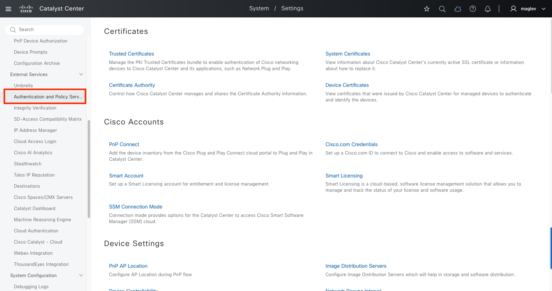
Table 7. Cisco recommended RTT for Cisco SD-Access deployment
| Source device |
Target device |
Maximum round trip time supported |
| Catalyst Center Node |
FE/Wireless Controller/Border/Control Plane |
200 ms |
| Catalyst Center Node |
Cisco ISE |
300 ms |
| Cisco ISE |
FE/Wireless Controller/Border/Control Plane |
100 ms |
| Wireless Controller |
APs |
20 ms |
| Wireless Controller |
Control Plane Node |
100 ms |
Table 8 through Table 12 list the scale number of endpoints, APs, VN and so on supported in different fabric roles of commonly used device families and Catalyst Center. For more detailed information and a full list of device families, see the Catalyst Center Data Sheet.
Table 8. Cisco SD-Access scale numbers for fabric edge nodes
| Device family |
Virtual networks |
Wired endpoints |
Directly connected AP |
| 9200-L |
1 |
2,000 |
Not supported |
| 9200 |
4 |
4,000 |
25 |
| 9300-L |
256 |
6,000 |
50 |
| 9300 |
256 |
6,000 |
200 |
| 9400 |
256 |
6,000 |
200 |
| 9500/H |
256 |
6,000 |
200 |
Table 9. Cisco SD-Access scale numbers for fabric border nodes
| Device family |
Virtual networks |
Fabric hosts entries (/32 or /128) |
| 9300-L |
256 |
16,000 |
| 9400 |
256 |
70,000 |
| 9500 |
256 |
70,000 |
| 9500-H |
256 |
150,000 |
| 9600 |
256 |
150,000 |
| ASR1K, 4K, ISR (8 GB RAM) |
128 |
1,000,000 |
| ASR1K, 4K, ISR (16 GB RAM) |
128 |
4,000,000 |
Table 10. Cisco SD-Access scale numbers for wireless controller models
| Wireless controller model |
Max. number of APs |
Max. number of clients |
| Catalyst 9800-L |
250 |
5,000 |
| Catalyst 9800-40 |
2,000 |
32,000 |
| Catalyst 9800-80 |
6,000 |
64,000 |
| Catalyst 9800-CL (4 CPU/8 GB RAM) |
1,000 |
10,000 |
| Catalyst 9800-CL (6 CPU/16 GB RAM) |
3,000 |
32,000 |
| Catalyst 9800-CL (10 CPU/32 GB RAM) |
6,000 |
64,000 |
| Embedded Wireless Controller on Catalyst 9000 (9300L) |
50 |
1,000 |
| Embedded Wireless Controller on Catalyst 9000 (9300,9400,9500,9500H) |
200 |
4,000 |
Table 11. Catalyst Center Cisco SD-Access system scale
| SKU |
DN-SW-APL |
DN3-HW-APL |
DN3-HW-APL-L (C220 M6 56 cores) |
DN2-HW-APL-XL (C480 M5 112 cores) |
| Devices (Switch, Router, WLC) (fabric) |
2000 |
2000 |
4000 |
8000 |
| Wireless Access Points (fabric) |
3000 |
3000 |
4000 |
10000 |
| Concurrent Endpoints |
25,000 |
25,000 |
40,000 |
100,000 |
| Transient Endpoints |
75,000 |
75,000 |
120,000 |
250,000 |
| Ratio of Endpoints to: Wired Wireless |
Any Any |
Any Any |
Any Any |
Any Any |
| Fabric Sites |
500 |
500 |
1000 |
2000 |
| Scalable groups |
4000 |
4000 |
4000 |
4000 |
| Global IP Pools |
100 |
100 |
100 |
200 |
| Layer 3 VN per site |
64 |
64 |
128 |
256 |
| Layer 2 VN per site |
200(1) |
200(1) |
600(2) |
1000(3) |
| IP Pools per site |
100(1) |
100(1) |
300(2) |
1000(3) |
| Fabric devices per site |
500 |
500 |
600 |
1200 |
Note:
(1) Per fabric site, the sum of IP pools plus layer 2 Virtual Networks must not exceed 200.
(2) Per fabric site, the sum of IP pools plus layer 2 Virtual Networks must not exceed 300.
(3) Per fabric site, the sum of IP pools plus layer 2 Virtual Networks must not exceed 1000.
Table 12. Scale for 3-node DN3-HW-APL-XL cluster
| Description |
Supported Scale |
| Devices (Switch, Router, wireless controller) |
10,000 |
| Wireless Access Points |
25,000 |
| Concurrent Endpoints |
300,000 |
| Transient Endpoints (over 14-day period) |
750,000 |
This section demonstrates the processes and procedures of designing the Cisco SD-Access network using Catalyst Center.
The processes for designing the Cisco SD-Access networks are as follows:
● Integrate Cisco ISE with Catalyst Center (required for microsegmentation).
● Configure the site hierarchy.
● Configure the network services required for Cisco SD-Access network operation.
● Configure the IP pools.
● Configure wireless settings for the WLAN deployment (required for a fabric wireless network).
For the process and procedure for installing Catalyst Center, see the Catalyst Center Installation Guide.
For the process and procedure for installing Cisco ISE, see the Cisco ISE installation Guide.
Integrate Cisco ISE with Catalyst Center
The integration of Cisco ISE and Catalyst Center enables sharing information between the two platforms, including device and group information. It is mandatory for a microsegmentation solution but optional for a macrosegmentation solution.
Use the procedures to integrate Cisco ISE with Catalyst Center include:
● Configure Cisco ISE as an authentication and policy server to Catalyst Center.
● Permit pxGrid connectivity from Catalyst Center into Cisco ISE.
Procedure 1. Configure Cisco ISE as an authentication and policy server
Step 1. From the top-left corner, click the menu icon and choose System > Settings then in the left panel choose External Services > Authentication and Policy Servers.
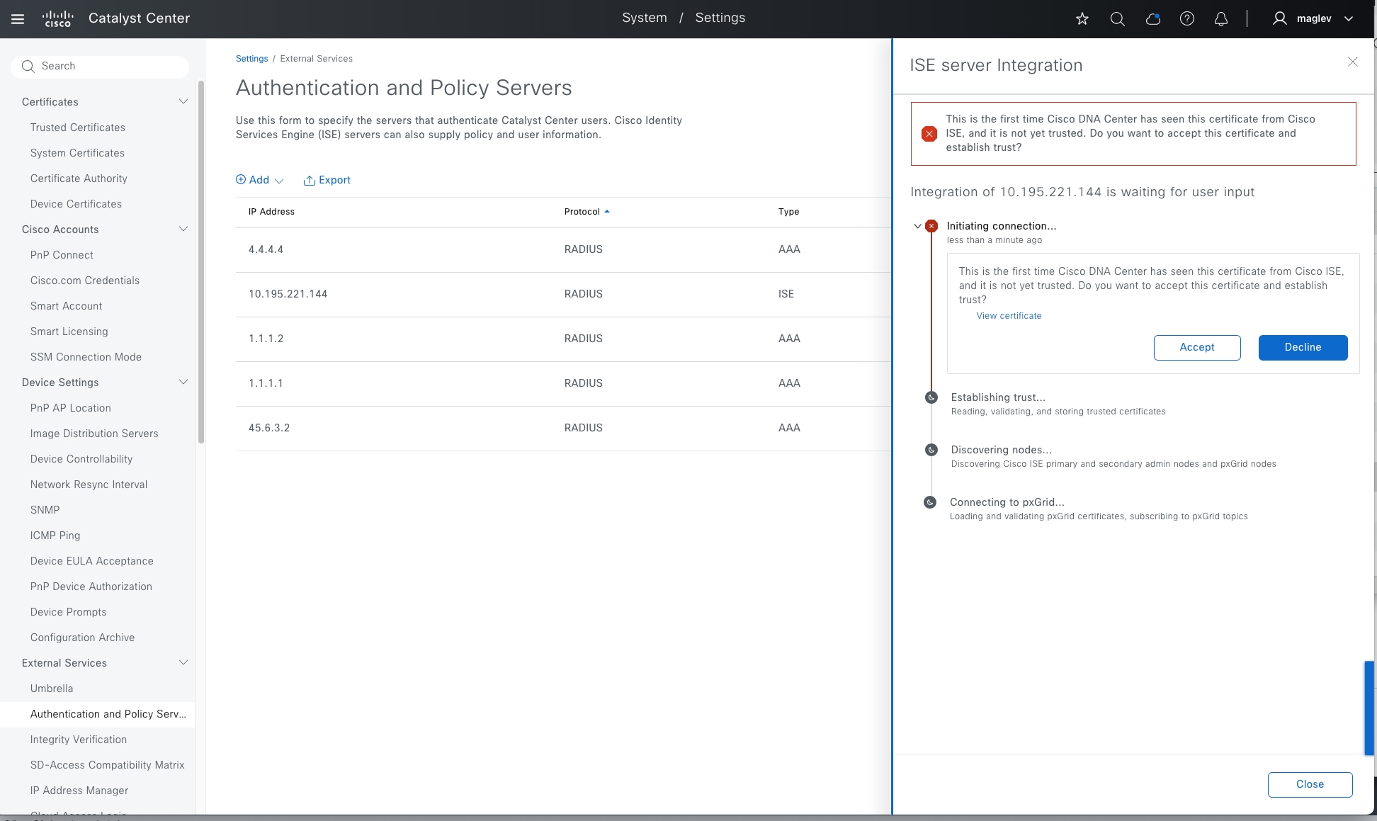
Step 2. Click Add then from the drop-down menu, select ISE.
Step 3. Enter the information within the Add ISE server pane.
The Table 13 explains the fields within the Add ISE server pane.
Table 13. Add AAA with ISE server pane fields
| Field |
Settings |
Description |
| Server IP Address |
Text Field |
The IP address of the Cisco ISE server. (Ensure this is the IP address shown on the Cisco ISE deployment instance if it has multiple IP addresses configured.) |
| Shared Secret |
Text Field |
This is used by network devices for communicating with the Cisco ISE server. This is also referred to the PAC key within an IOS XE device configuration. |
| Username |
Text Field |
This is the username of the default super admin account that you created during the Cisco ISE installation. |
| Password |
Text Field |
This is the password of the default super admin account that you created during the Cisco ISE installation. |
| FQDN |
Text Field |
This is the fully qualified domain name of the Cisco ISE server. |
| Virtual IP Address |
Text Field |
This can have one or more PSN behind a single load balancer. In those cases, you can add the load balancer IPs in the Virtual IP field. |
| Advanced Settings > Protocol |
Multiple Choice Radio Button |
This determines the authentication protocols used. The choices are as follows: RADIUS: This is the default setting, using the RADIUS protocol TACACS: Uses the TACACS protocol |
| Advanced Settings > Authentication Port |
Text Field |
This uses 1812 for the default port when RADIUS is selected. |
| Advanced Settings > Accounting Port |
Text Field |
This uses 1813 for the default port when RADIUS is selected. |
| Advanced Settings > Port |
Text Field |
This field appears only when TACACS is selected. The default port is 49. |
| Retries |
Number |
This is the number of authentication-retries before failure. The default is 3. |
| Timeout (seconds) |
Number |
This is the number of seconds before an attempt times out. The default is 4 seconds. |
For this design and deployment guide, the information in Table 14 was entered.
Table 14. Add AAA with ISE server pane fields
| Field |
Value |
| Server IP Address |
10.195.221.144 |
| Shared Secret |
**** |
| Cisco ISE Server |
On |
| Username |
Admin |
| Password |
**** |
| FQDN |
FANIU-ISE-V3.cisco.cpm |
| Subscriber Name |
Admin |
| SSH Key |
None (empty) |
| Virtual IP Address |
None (empty) |
| Advanced Settings > Protocol |
RADIUS |
| Advanced Settings > Authentication Port |
1812 |
| Advanced Settings > Accounting Port |
1813 |
| Retries |
3 |
| Timeout (seconds) |
4 |
Before adding Cisco ISE ensure theses prerequisites are met:
● Cisco ISE and Catalyst Center have compatible versions (see Catalyst Center Compatible Matrix).
● Cisco ISE GUI password matches Cisco ISE CLI password (this restriction is removed in Catalyst Center 2.3.7.6 and later releases).
● pxGrid is enabled for the Cisco ISE deployment instance.
● On Cisco ISE the ERS is Read/Write Enabled.
Step 4. Click Add to create the Cisco ISE server within Catalyst Center.
Step 5. When the sidebar with a certificate of Cisco ISE to be trusted displays, click Accept.
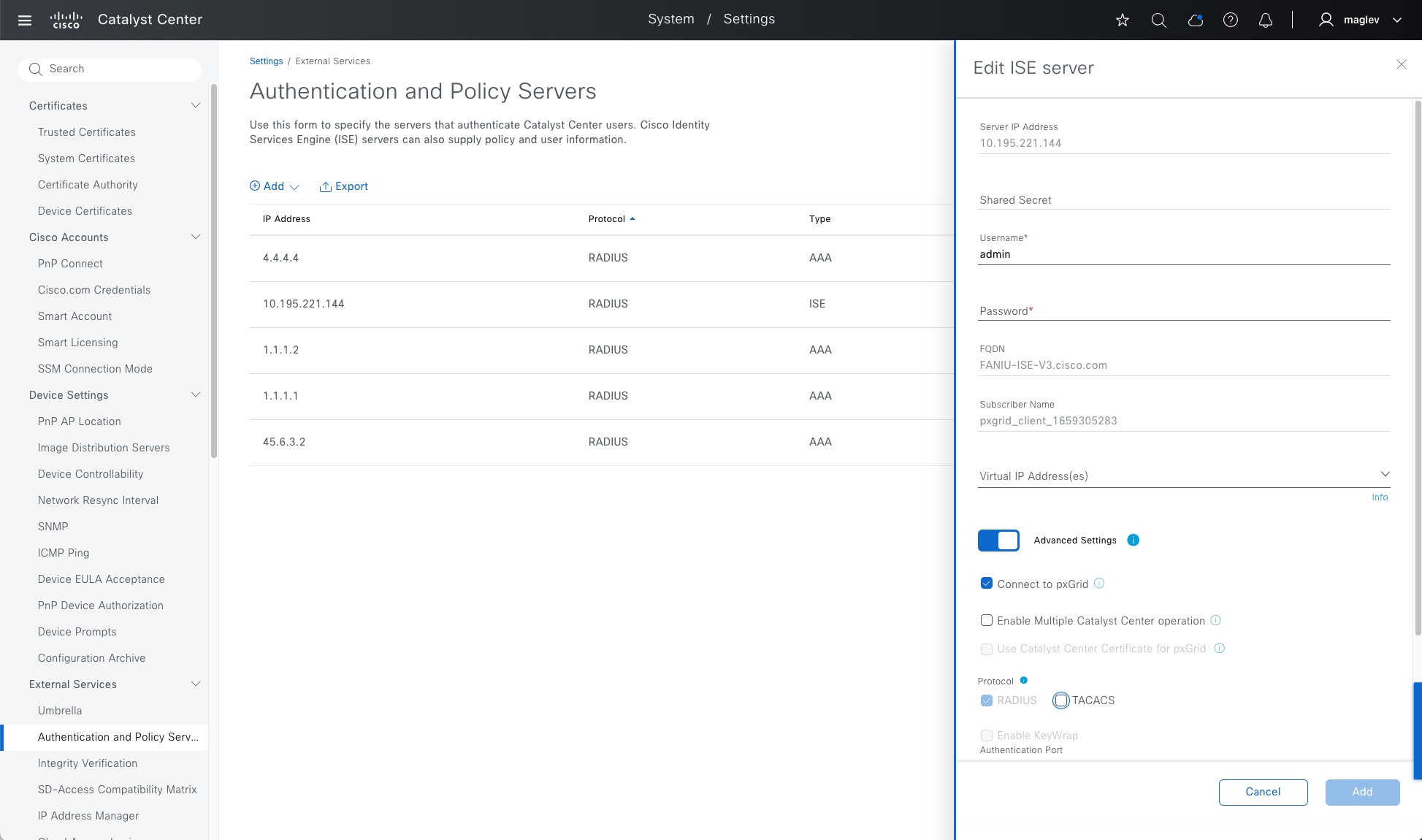
When the integration finishes, you return to the Authentication and Policy Servers dashboard. The new Cisco ISE server shows with a Status of Active. If you must change or correct any settings, select it and click Edit.
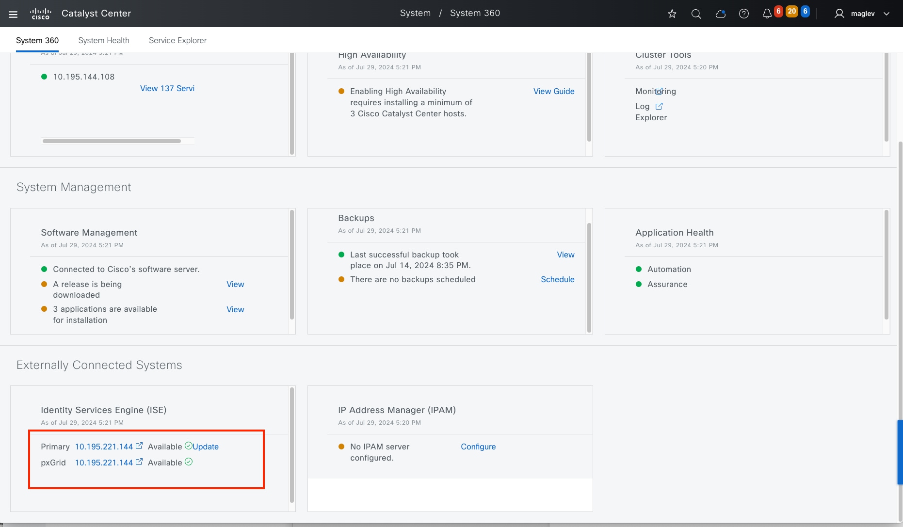
To confirm Catalyst Center is integrated with Cisco ISE, within Catalyst Center:
Step 6. From the top-left corner, click the menu icon and choose System > System 360 then scroll to the Externally Connected Systems > Identity Services Engine (ISE) section.
Primary and pxGrid should both show as Available.
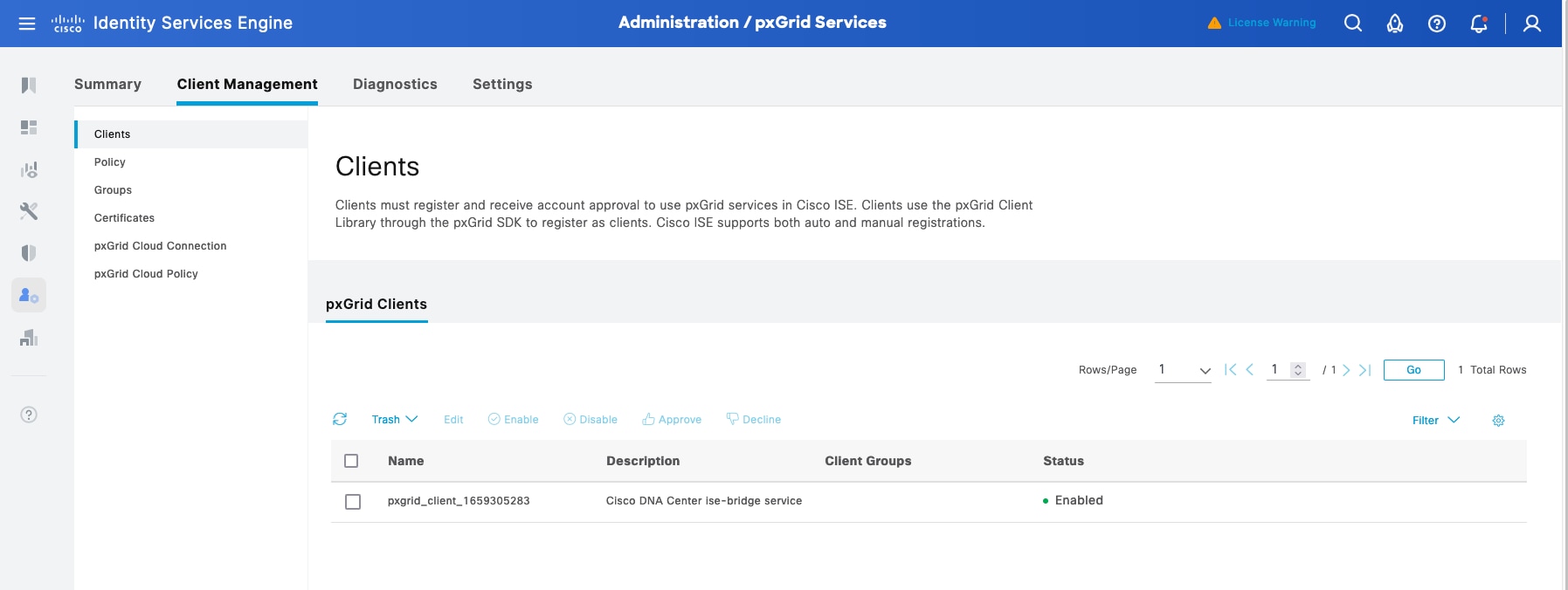
Step 7. In Cisco ISE, from the top-left corner, click the menu icon and choose Administration > pxGrid Services then click the Client Management tab. Confirm that the pxGrid session with the Cisco Catalyst session is created and that the Status shows as Enabled.
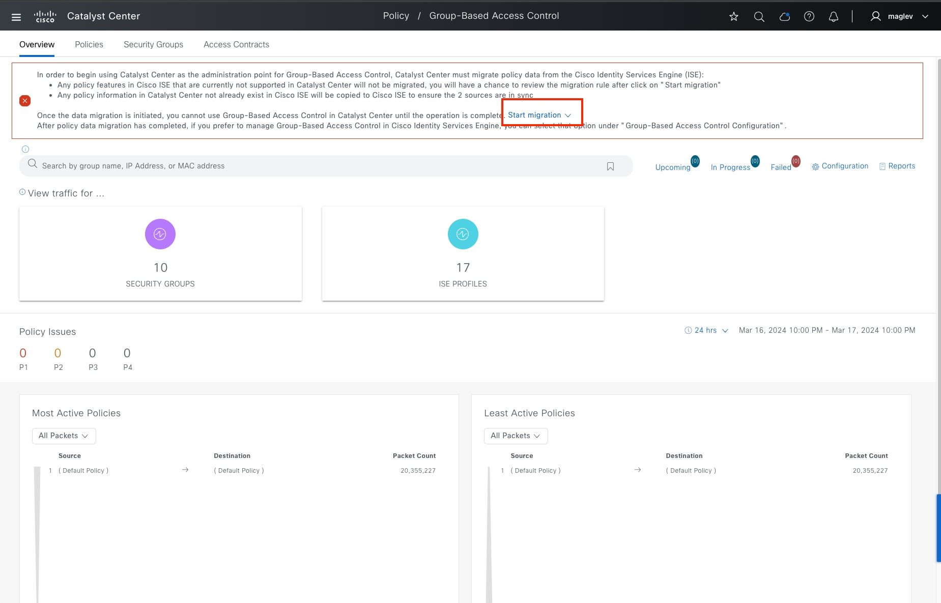
Procedure 2. Integrate with Catalyst Center policy window
To use Catalyst Center as the administrator for GBAC, Catalyst Center must migrate policy data from the ISE.
Step 1. From the top-left corner, click the menu icon and choose Policy > Group-Based Access Control.
Step 2. Click Start migration from the banner. Migration can be scheduled later or start immediately. It can take up to one hour depending on the data scale.
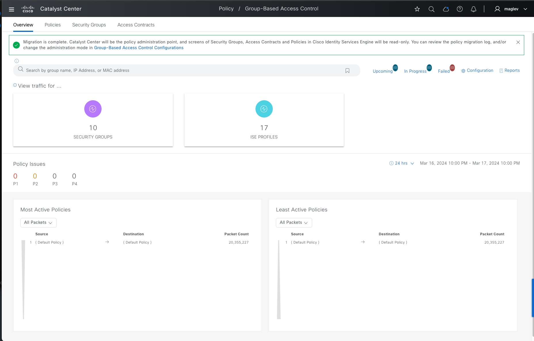
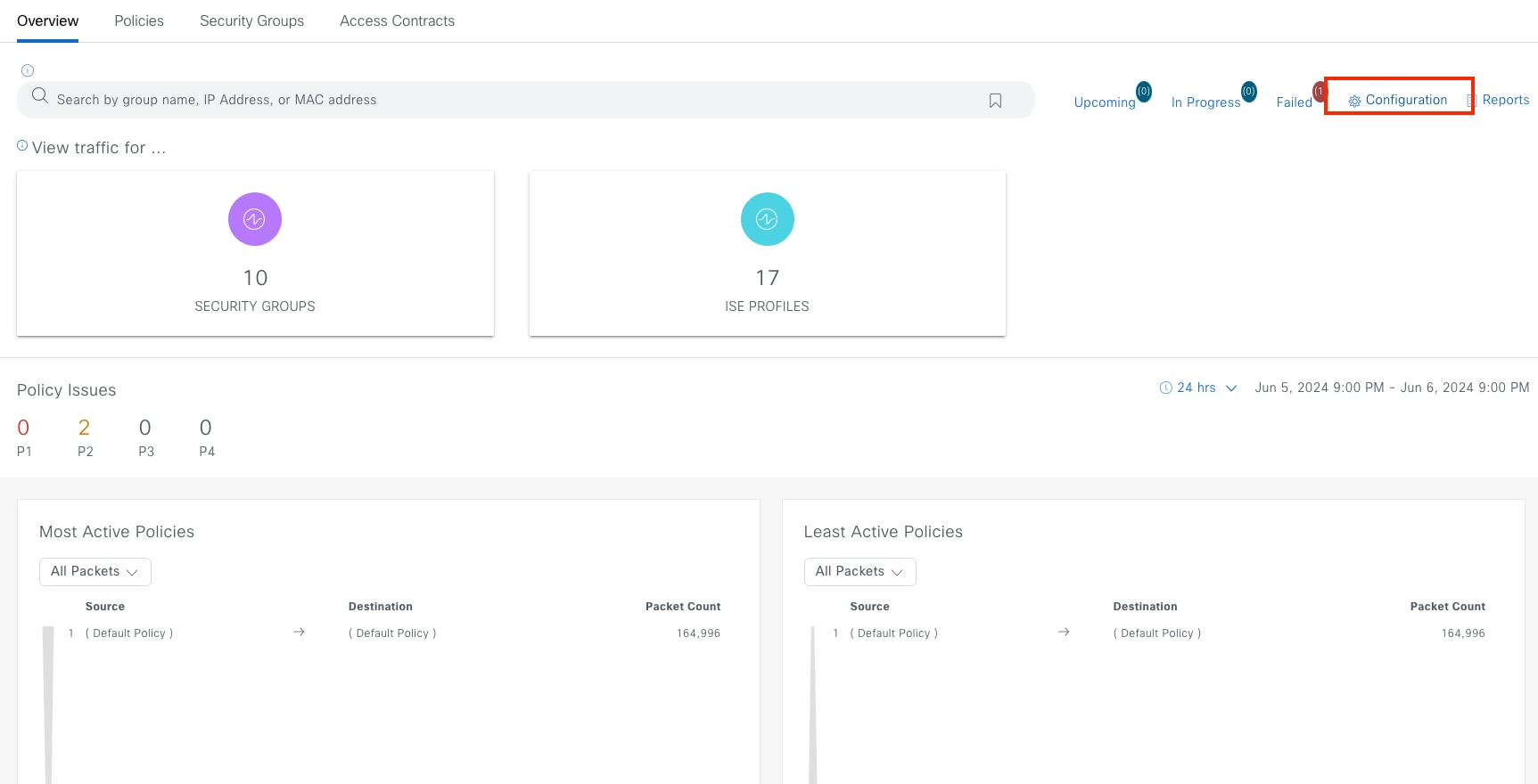
Note:
Any policy features in Cisco ISE that are currently not supported in Catalyst Center will not be migrated. Network administration provides the ability to review the migration rule after you click Start migration.
Any policy information in Catalyst Center not already existing in Cisco ISE is copied to Cisco ISE to ensure the two sources are synchronized.
After an upgrade, navigate to the same place. Migration must be re-done to ensure Catalyst Center and Cisco ISE are synchronized.
Procedure 3. Change Administration Mode
Catalyst Center provides the option to define the Administration Mode.
If Cisco ISE is preferred as the administration point and switching the administration point between Cisco ISE and Catalyst Center is required:
Step 1. From the top-left corner, click the menu icon and choose Policy > Group-Based Access Control then click the Overview tab.
Step 2. Click Configuration.
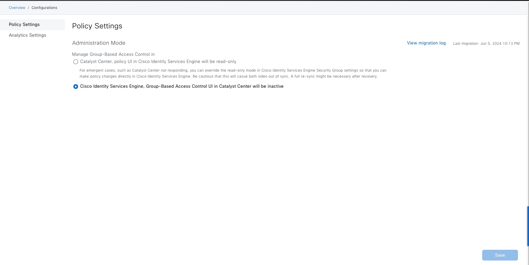
Step 3. Choose one of options for the administration point.
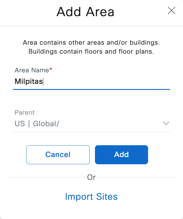
Configure the site hierarchy
Configuring the site hierarchy involves defining the network sites for the deployment, and their hierarchical relationships. Network sites consist of areas, buildings, and floors. Their hierarchical relationship is important because child sites automatically inherit certain attributes from parent sites. However, these attributes may be overridden within the child site.
Table 15 summarizes the site hierarchy for this design and deployment guide. A single area (Milpitas) with multiple Buildings (Cisco-building-24), (Floor 1 and Floor 2) is provisioned.
Table 15. Design and deployment guide site hierarchy
| Name |
Type of Site |
Parent |
Additional Information |
| Milpitas |
Area |
Global |
|
| Building 24 |
Building |
Milpitas |
Address: 510 McCarthy Boulevard, Milpitas, California, 95035 |
The procedures for configuring the site hierarchy for this design and deployment guide include:
● Create an area.
● Create buildings within the area.
● Create floors within each building and import floor maps (optional).
Procedure 1. Create an area
Step 1. From the top-left corner, click the menu icon and choose Design > Network Hierarchy.
Step 2. In the Network Hierarchy dashboard, choose Add Site > Add Area.
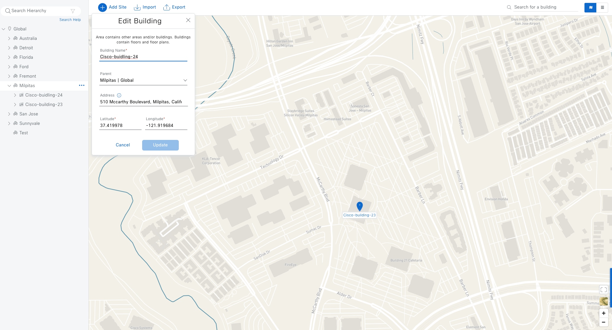
Procedure 2. Create buildings within the area
Adding buildings can be done through the Add Site drop-down list or through the Global > Milpitas in the navigation pane on the left side.
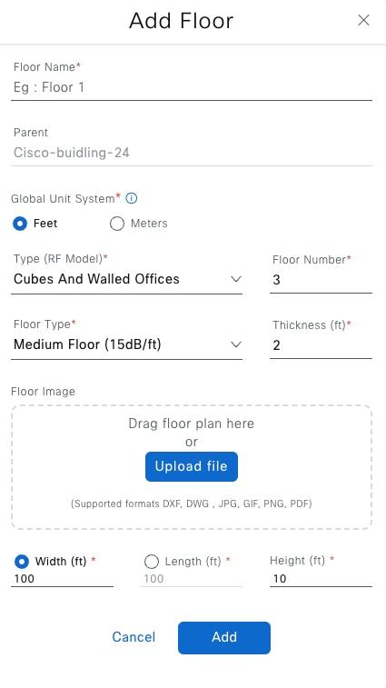
Step 1. Type a Building Name in the field. For this example, type: Cisco-building-24.
Step 2. For Cisco-building-24, type the Address in the field.
Step 3. Choose Parent > Milpitas.
Step 4. Repeat Step 1 and Step 2 to add a second building example. For this example, type: Cisco-building-23.
Procedure 3. Create floors within the buildings
AP locations and wireless coverage (heatmaps) can be displayed from the floor maps. Floors are referenced during wireless provisioning.
Adding floors can be done through the Add Site drop-down list or through Global > Cisco-building-24 and Global > Cisco-building-23 in the navigation pane on the left side.
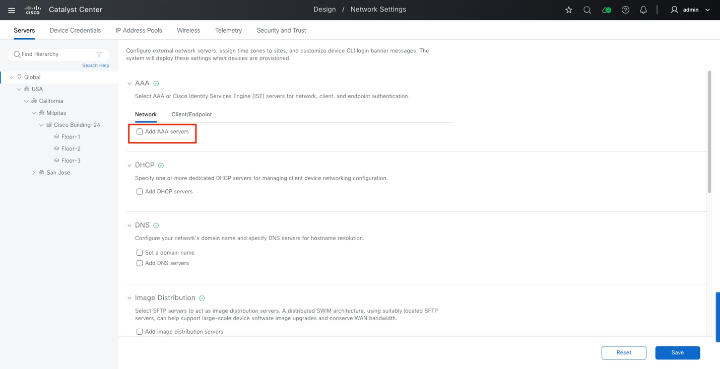
Step 1. Type a first floor Floor Name in the field for the Parent (example: Cisco-building-24).
Step 2. (Optional) Upload a Floor Image map.
Step 3. Repeat Step 1 and Step 2 to add a second floor.
Configure network services necessary for network operation
In Catalyst Center, common network resources and settings are saved in the Network Settings tab of the design application.
Configurable common network settings in the design application include Authentication, Authorization, and Accounting (AAA) server, DHCP server, DNS server, Syslog server, SNMP server, NetFlow collector, NTP server, time zone, message of the day, and telemetry. Several of these capabilities are used for Catalyst Center Assurance deployment.
By default, when clicking the Network Settings tab, newly configured settings are assigned as Global network settings. They are applied to the entire hierarchy and inherited by each site, building, and floor. In Network Settings, the default selection point in the hierarchy is Global.
Tech tip: You can define specific network settings and resources for specific sites.
Procedure 1. Configure AAA, DHCP, DNS, NTP
Step 1. From the top-left corner, click the menu icon and choose Design > Network Settings, click Global in the navigation pane on the left side.
Step 2. Locate the AAA section and check the Add AAA servers check box.
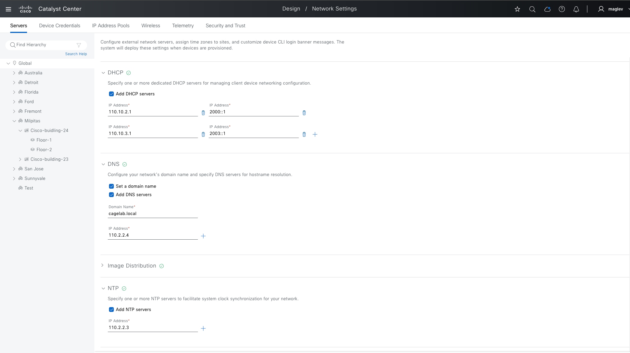
This guide uses Cisco ISE as the AAA server using the RADIUS protocol for both network devices and for clients.
Step 3. Enter the necessary information provided in Table 16.
Table 16. AAA server fields
| Field |
Value |
| Network |
Checked |
| Client/Endpoint |
Checked |
| Network > Servers |
ISE |
| Network > Protocol |
RADIUS |
| Network > Network |
10.195.221.144 |
| Network > IP Address (Primary) |
110.2.2.1 |
| Network > Shared Secret |
****** |
| Client/Endpoint > Servers |
ISE |
| Client/Endpoint > Protocol |
RADIUS |
| Client/Endpoint > Network |
10.195.221.144 |
| Client/Endpoint > IP Address (Primary) |
110.2.2.1 |
| Client/Endpoint > Shared Secret |
****** |
Step 4. Locate the DHCP Server section and enter the necessary information.
Catalyst Center supports both IPV4 and IPV6 DHCP servers and multiple DHCP servers can be added.
| Field |
Value |
| DHCP server |
110.10.2.1, 2000::1 |
| 110.10.3.1, 2003::1 |
Step 5. Locate the DNS Server section and enter the necessary information.
Table 17. DNS Server
| Fields |
Value |
| Domain Name |
cagelab.local |
| Primary |
110.2.2.4 |
Step 6. Locate the NTP Servers section and enter the necessary information.
Multiple NTP servers can be added for resiliency and accuracy. Time synchronization within a network is essential for any logging functions, as well as secure connectivity such as SSH.
Table 18. NTP server fields
| Fields |
Value |
| IP Address |
110.2.2.3 |
Step 7. Locate the Time Zone section and enter the necessary information.
Table 19. Time zone fields
| Fields |
Value |
| Time Zone |
GMT |
Step 8. After filling in all the sections, click Save to save the changes to the network services.
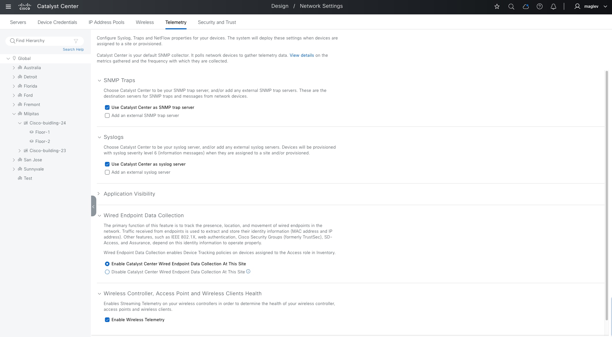
Procedure 2. Configure Telemetry, SNMP, Syslog
Catalyst Center can be configured as SNMP and Syslog server; external SNMP and Syslog servers are also supported. If Catalyst Center is configured as SNMP and Syslog server, SNMP traps and Syslogs are processed by Catalyst Center Assurance applications and reported on Assurance Dashboard.
The Wired Endpoint Data Collection option is to track the presence, location, and movement of wired endpoints in the network. The traffic received from the endpoints is used to extract and store the identity information (MAC address and IP address). It is mandatory for fabric sites. Configuration is pushed to all devices with an Access role.
The Wireless Controller, Access Point and Wireless Clients Health option enables Streaming Telemetry on the wireless controllers to determine the health of the wireless controller, APs, and wireless clients.
Step 1. From the top-left corner, click the menu icon and choose Design > Network Settings.
Step 2. Click the Telemetry tab.
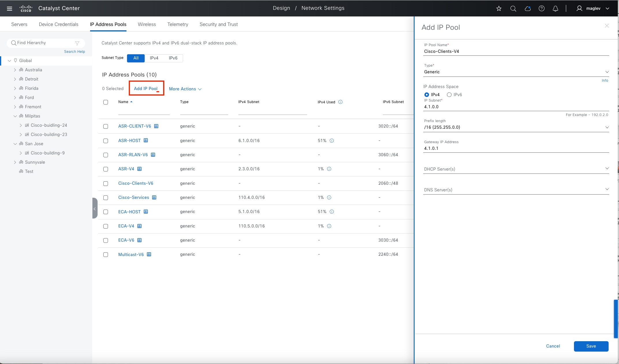
Configure an IP pool
The Catalyst Center IPAM (IP Address Management) tool is used to create and reserve IP address pool. IP address pools in SD Access network are used to assign IP address to endpoints such as wired clients, wireless clients, AP and Extended nodes. Additionally, Catalyst Center uses IP pools for LAN automation and border automation layer 3 handoff, multicast RP configuration and so on.
IP address pools are defined at the global level and then reserved at the area, building, or floor level where the Fabric option is enabled.
Catalyst Center supports adding IPv4 and IPv6 pools at the global level but only supports IPv4 or IPv4 and IPv6 dual stack pools when reserving at the site level. A pure IPV6 pool is not supported.
Note: Dual Stack Pools are not supported in LAN automation, APs and extended node onboarding.
The procedures in this section add and reserve IP pools for LAN automation, clients, AP, extended node, layer 3 handoff, and multicast for Cisco-building-24.
Procedure 1. Add an IP pool at the global level
Step 1. From the top-left corner, click the menu icon and choose Design > Network Settings.
Step 2. Click the IP Address Pools tab and click Global in the navigation pane on the left side.
Step 3. Click Add IP Pool.
Step 4. In the slide-in pane on the right, click IPv4, enter the required field information then click Save.
Step 5. Click Add IP Pool.
Step 6. In the slide-in pane on the right, click IPv6, enter the required field information then click Save.
| Global Pools |
IP Subnet |
Gateway |
| Cisco-Clients-V4 |
4.1.0.0/16 |
4.1.0.1 |
| Cisco-Clients-V6 |
2060: :/48 |
2060::1 |
| Cisco-Services |
110.4.0.0/16 |
110.4.0.1 |
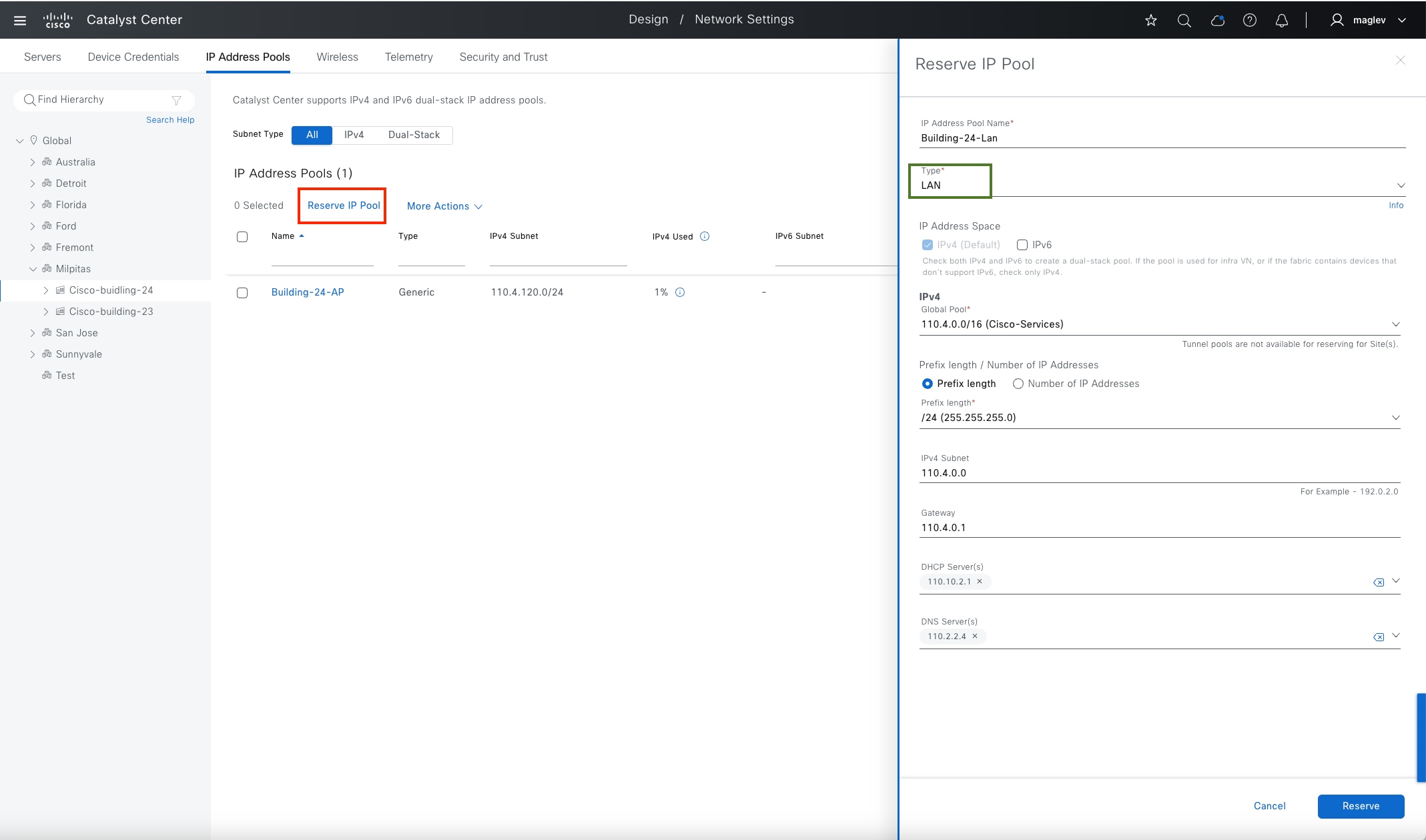
Note: DHCP servers and DNS servers are optional and can be configured at the site level.
Procedure 2. Reserve IP pools for a fabric site
The fabric site Cisco-Building-24 uses these planned IP address pools:
| Pool Use |
Name |
IP Subnet |
Gateway |
DHCP |
DNS |
| Access Points |
Building-24-AP |
110.4.120.0/24 |
110.4.120.1 |
110.10.2.1 |
110.2.2.4 |
| Extended Node |
Building-24-EN |
110.4.60.0/24 |
110.4.60.1 |
110.10.2.1 |
110.2.2.4 |
| Clients Pool -1 |
Building-24-Emp |
4.1.64.0/18 |
4.1.64.1 |
110.10.2.1 |
110.2.2.4 |
| Clients Pool -2 |
Building-24-Guest |
4.1.0.0/18 |
4.1.0.1 |
110.10.2.1 |
110.2.2.4 |
| LAN Automation |
Building-24-Lan |
110.4.0.0/24 |
110.4.0.1 |
110.10.2.1 |
110.2.2.4 |
| L3 Handoff |
Building-24-L3 |
110.4.100.0/24 |
110.4.100.1 |
|
|
| Multicast |
Building-24-RP |
110.4.224.0/24 |
110.4.224.1 |
|
|
Note: Multiple DHCP and DNS can be configured on a single pool. IP address assignment in layer 3 handoff and multicast are done by Catalyst Center. DHCP and DNS are not required.
Step 1. From the top-left corner, click the menu icon and choose Design > Network Settings.
Step 2. Click the IP Address Pools tab.
Step 3. In the navigation pane on the left side, choose Milpitas > Cisco-building-24.
Step 4. Click Reserve IP Pool.
Step 5. In the Reserve IP Pool slide-in pane on the right side, use the information from the table to complete the fields.
For the LAN Automation pool use, select LAN for the Type field. For all other pools, select Generic for the Type field.
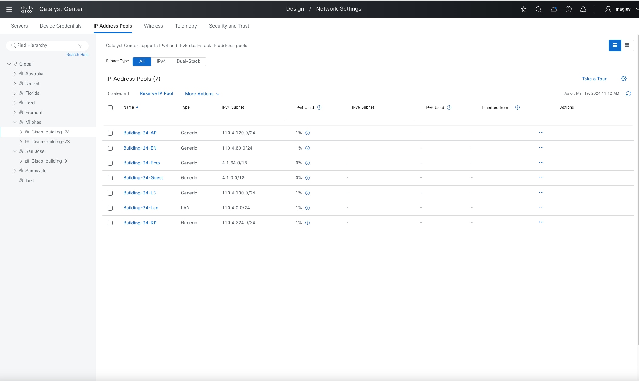
Step 6. Reserve all the pools listed in the table.
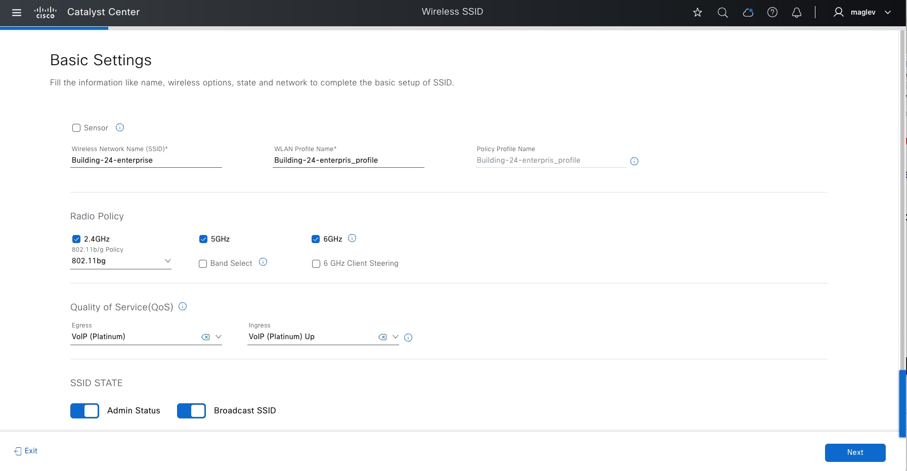
Configure a wireless SSID
WLANs with SSIDs are used to broadcast available wireless network across the deployment. They must be defined at the Global level of the site hierarchy and then inherited and used on the site level. On the site level, parameters of the inherited SSIDs can be edited and tuned.
Catalyst Center supports creating Enterprise and Guest SSIDs.
Creating the SSID involves defining the name along with the type of wireless network (voice, data, or both), wireless band, security type, and advanced options.
The wireless profile defines whether the wireless network is fabric or nonfabric and defines to which sites and locations within the hierarchy the profile is assigned. Wireless configurations, like IP address pools, are configured at the global level of the hierarchy.
For more and detailed information for Wireless SSID, see Catalyst Center User Guide, section ‘Configure Global Wireless Settings’.
Procedure 1. Configure Enterprise SSID
The wireless workflow to create an enterprise wireless SSID involves:
1. Create the SSID and its parameters.
2. Create the wireless profile.
This deployment guide configures a single enterprise WLAN with SSID named Building-24-enterprise.
To configure the enterprise wireless network within Catalyst Center:
Step 1. From the top-left corner, click the menu icon and choose Design > Network Settings then click the Wireless tab to open the dashboard.
Step 2. Click SSID, click Add then click Enterprise.
The first step in the Create an Enterprise Wireless Network workflow appears.
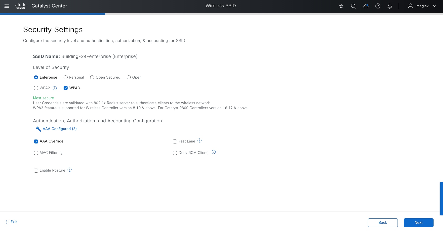
Step 3. Set the Security Settings for Enterprise SSID with AAA servers.
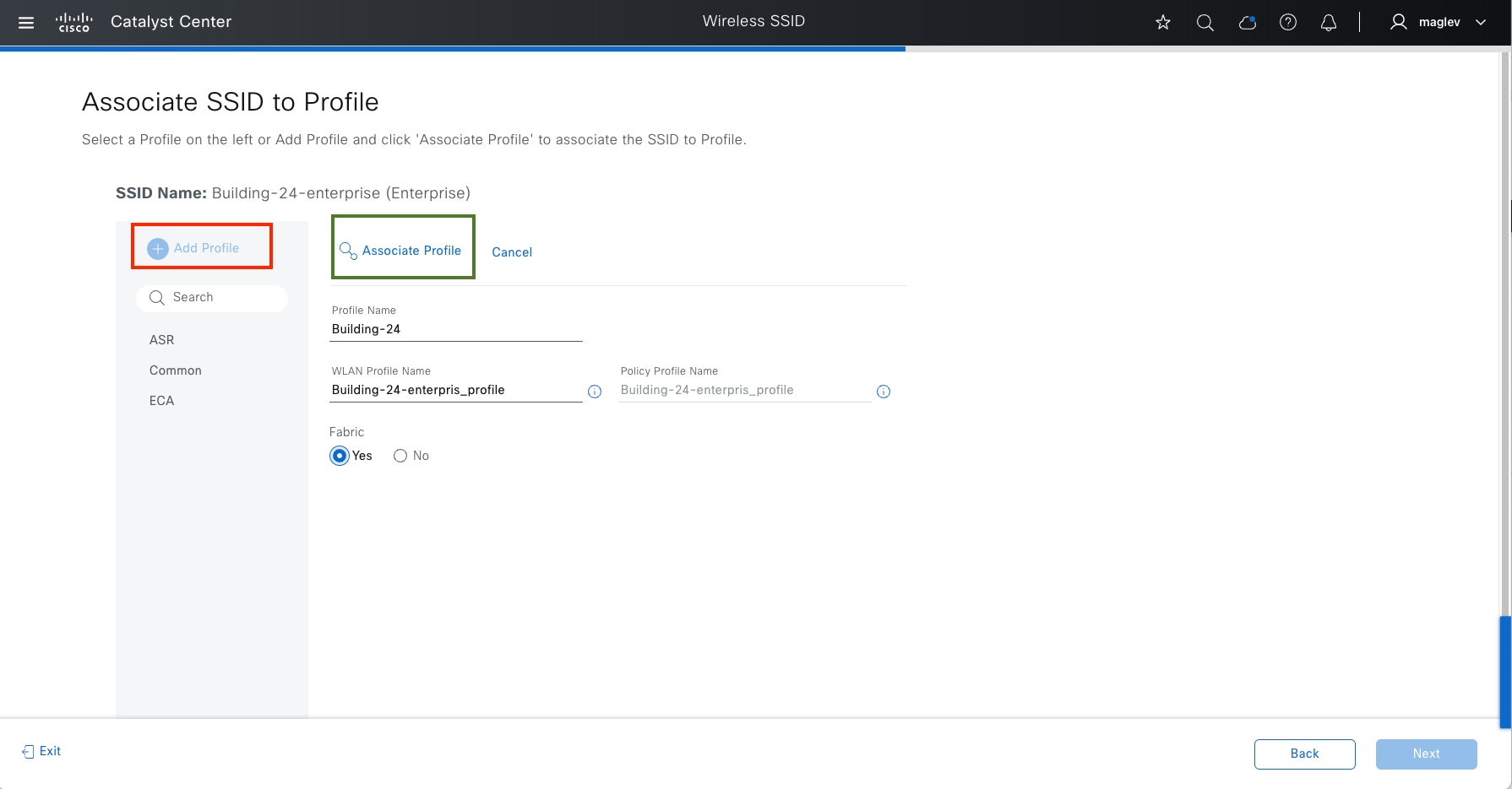
Step 4. Continue with Advanced Settings and Model Config association (optional) and Associate SSID to Profile:
1. Click Add Profile to create a new profile (Building-24) and click Yes as the Fabric option.
2. Click Associate Profile to SSID.
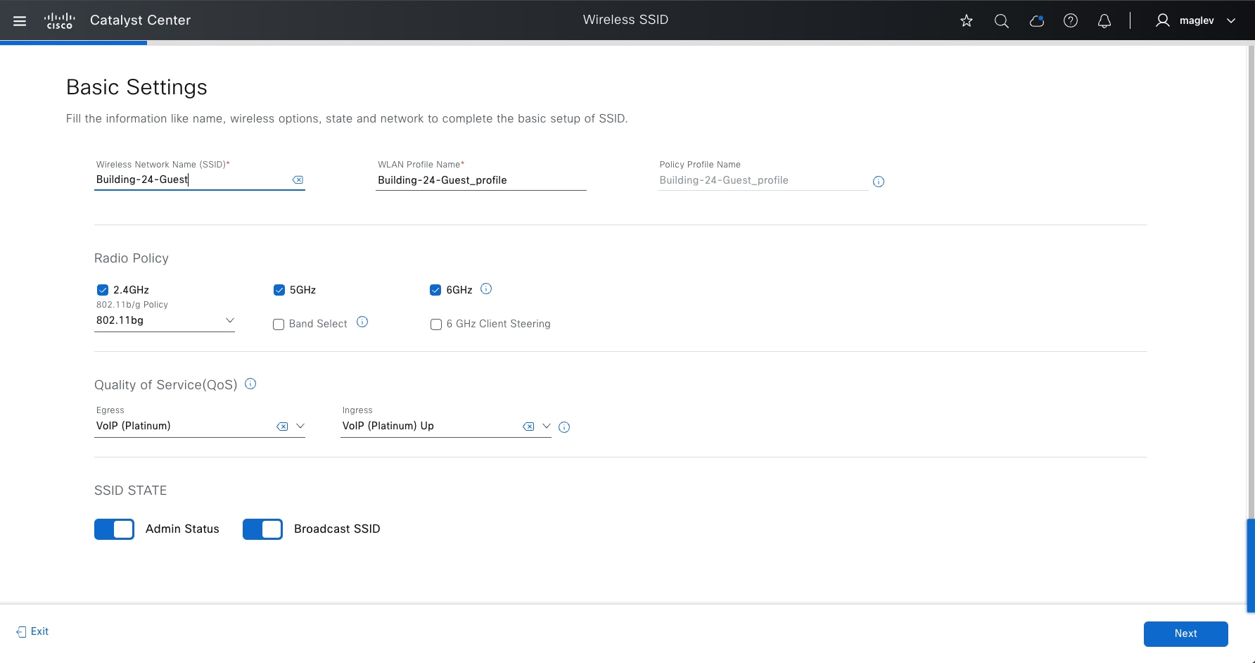
Tech tip: A new profile can be created from the Network Profiles window (Design > Network Profiles) and assigned to a site before creating the SSID.
Step 5. Complete the workflow. The new SSID Building-24-enterprise shows in the SSID dashboard.
Procedure 2. Configure Guest SSID
Designing the Guest wireless SSID is like designing the Enterprise wireless SSID. The primary difference is the Guest Web Authentication section in the workflow. Catalyst Center supports External Web Authentication and Central Web Authentication.
External Web Authentication uses the specified URL to redirect the guest users. Central Web Authentication uses the Guest Portal sequence of the Identity Services Engine to redirect guest users to the captive portal hosted on Cisco ISE.
The Guest wireless SSID creation workflow is a three-step process:
1. Create the SSID and its parameters.
2. Create the wireless profile.
3. Create the portal.
For this deployment guide, a single guest wireless network (SSID) named Building-24-Guest is provisioned.
To configure guest wireless networks within Cisco Catalyst Center:
Step 1. From the top-left corner, click the menu icon and choose Design > Network Settings then click the Wireless tab to open the dashboard.
Step 2. Click SSID, click Add then click Guest.
This option displays the first step in the Create a Guest Wireless Network workflow.
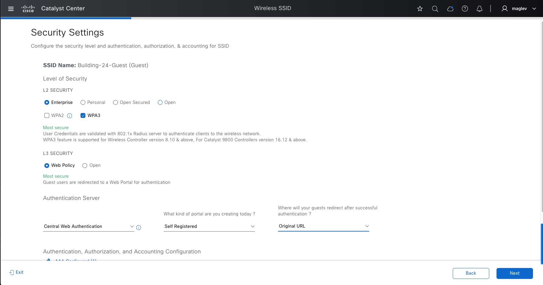
Step 3. Set the Security Settings for the Guest SSID with AAA servers and Authentication Server fields: Central Web Authentication, Self-Registered, Original URL.
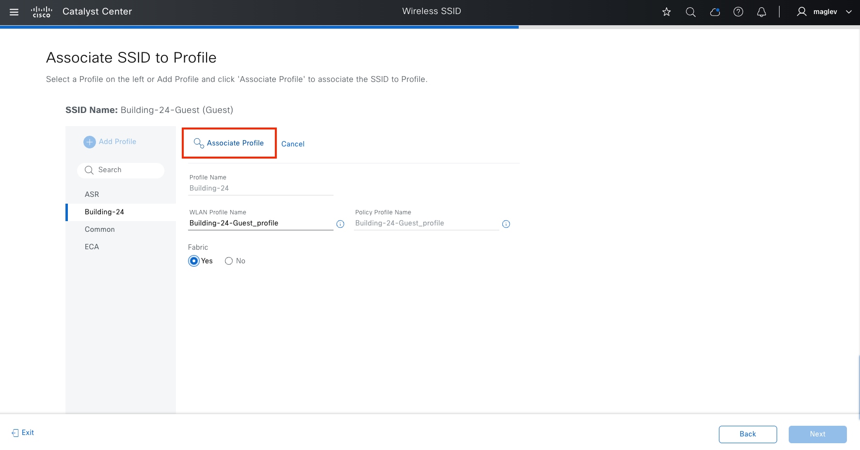
Step 4. Continue with Advanced Settings and Model Config association (optional) and Associate SSID to Profile:
1. Choose Building-24 (defined in previous procedure) and click Yes as the Fabric option.
2. Click Associate Profile to SSID.
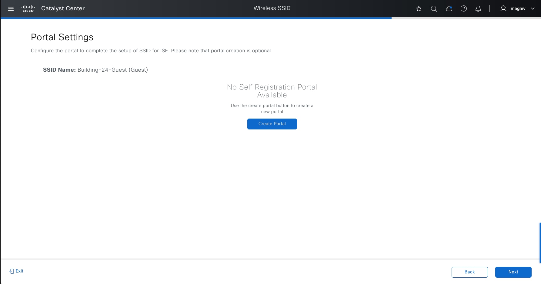
Step 5. Add a new guest portal within Cisco ISE.
1. Click the Create Portal button.
2. In the Portal Builder window enter Building-24-Guest for the Portal Name.
3. Click Login Page and finish the workflow.
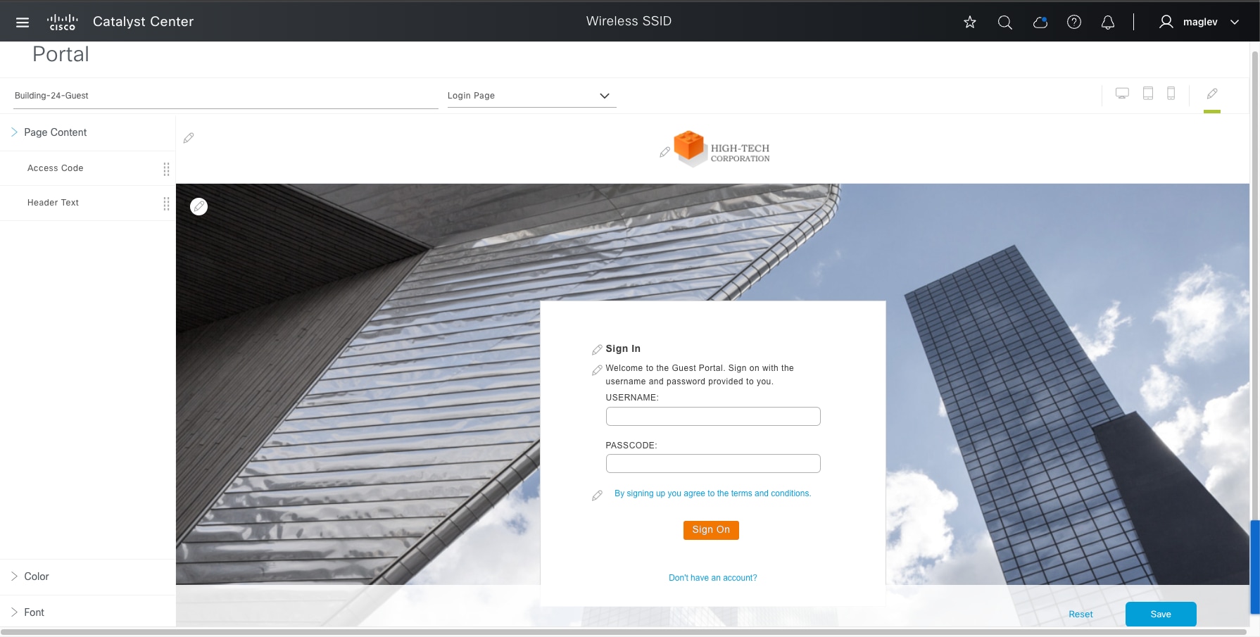

After creating a guest SSID with a guest portal, Catalyst Center pushes the required authentication, authorization and guest portal configurations to Cisco ISE according to the settings in the guest SSID profile.
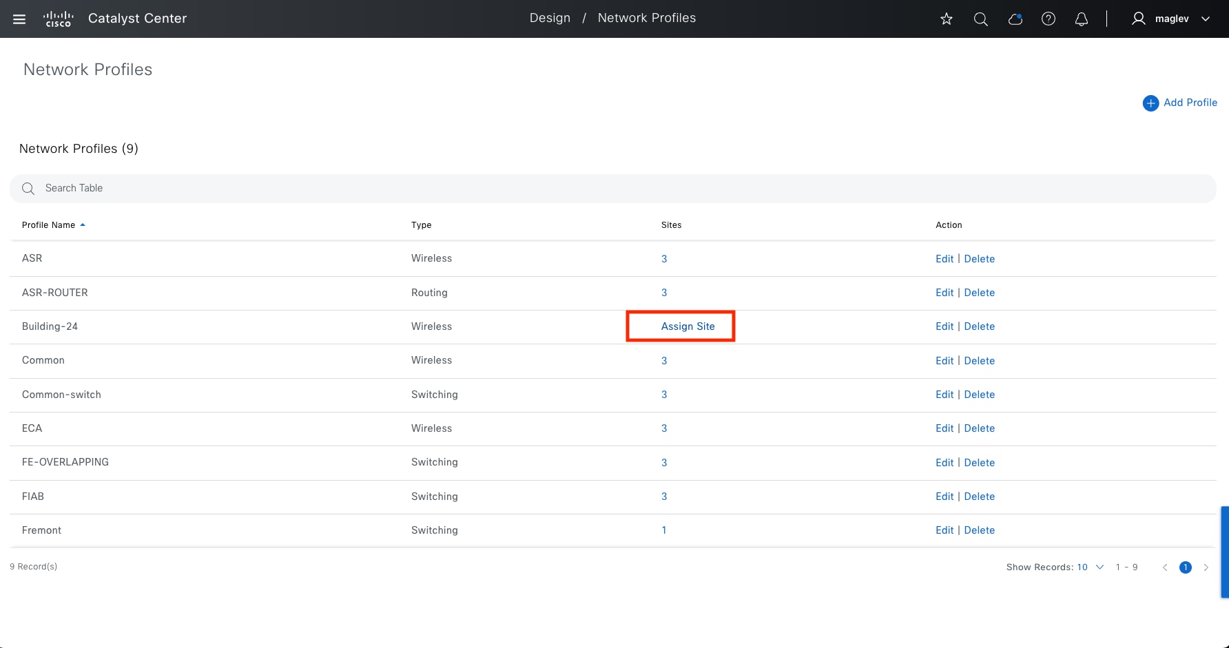
Procedure 3. Assign a network profile to the site
After creating SSIDs, assign a network profile, which defines the location requirements, to the site.
Step 1. From the top-left corner, click the menu icon and choose Design > Network Profiles.
Step 2. Locate the Profile Name listed as Building-24 (created in the previous procedure) then click Assign Site.
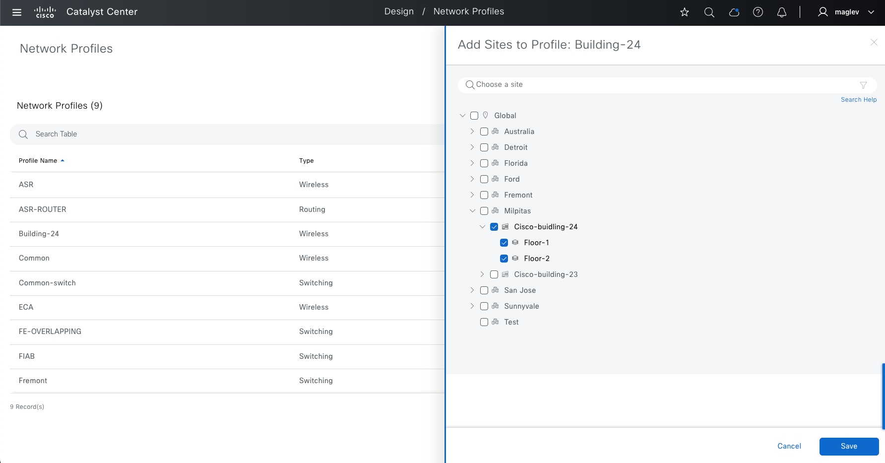
Step 3. In the slide-in pane, check the Building-24 check box then click Save.
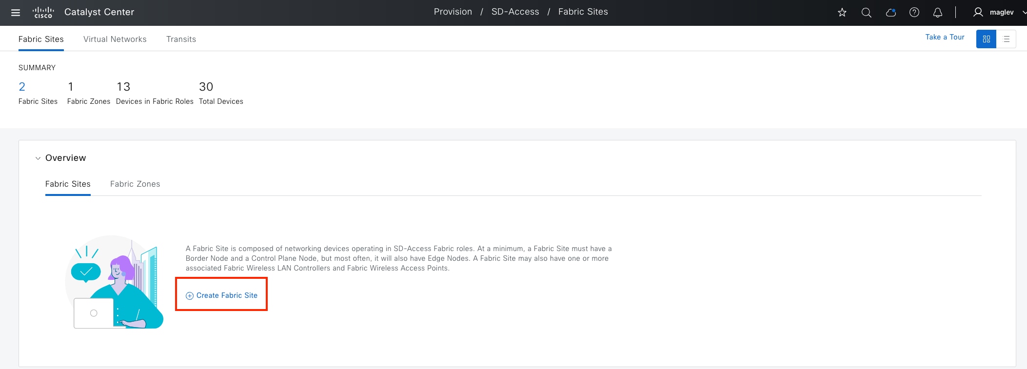
Configure fabric sites and fabric zones
A fabric site is an independent fabric area with a unique set of network devices; control plane, border node, edge node, wireless controller, Cisco ISE PSN. Different levels of redundancy and scale can be designed for each site by including local resources; DHCP, AAA, DNS, internet, and so on. A fabric site can cover a single physical location, multiple locations, or only a subset of a location as well.
Fabric zones allow VNs, or IP pools to be restricted to a contained set of specified fabric edge nodes. This concept helps customers who have large-scale deployments of fabric edge nodes in a single fabric site and need a way to manage the network based on smaller locations, or zones. These zones could be multiple buildings or multiple floors within a building.
Note:
Fabric zones must be manually enabled by the network administrator based on design considerations.
Fabric zones are child sites of a parent fabric site and can be configured on building-level or floor-level within a fabric site. If a fabric zone is enabled at a building-level, all the floors within this building become part of the same fabric zone.
Fabric zones can be enabled for day-zero or day-n operations. For day-zero operations, by default, fabric zones do not have any VNs, or IP pools. Specifically add the required VN and IP pools to fabric zones. For day‑n operations, fabric zones inherit all VNs and pools that are mapped to a fabric site. Delete the VN, or IP pool that is not required in the fabric zone.
Fabric zone is not applicable for fabric wireless deployment. IP Pools mapped with fabric SSID need to be configured in all fabric edges.
Procedure 1. Enable fabric on a site
Step 1. From the top-left corner, click the menu icon and choose Provision > Fabric Sites. The Summary view is the default landing window.
The Fabric Site can be created from different places, including:
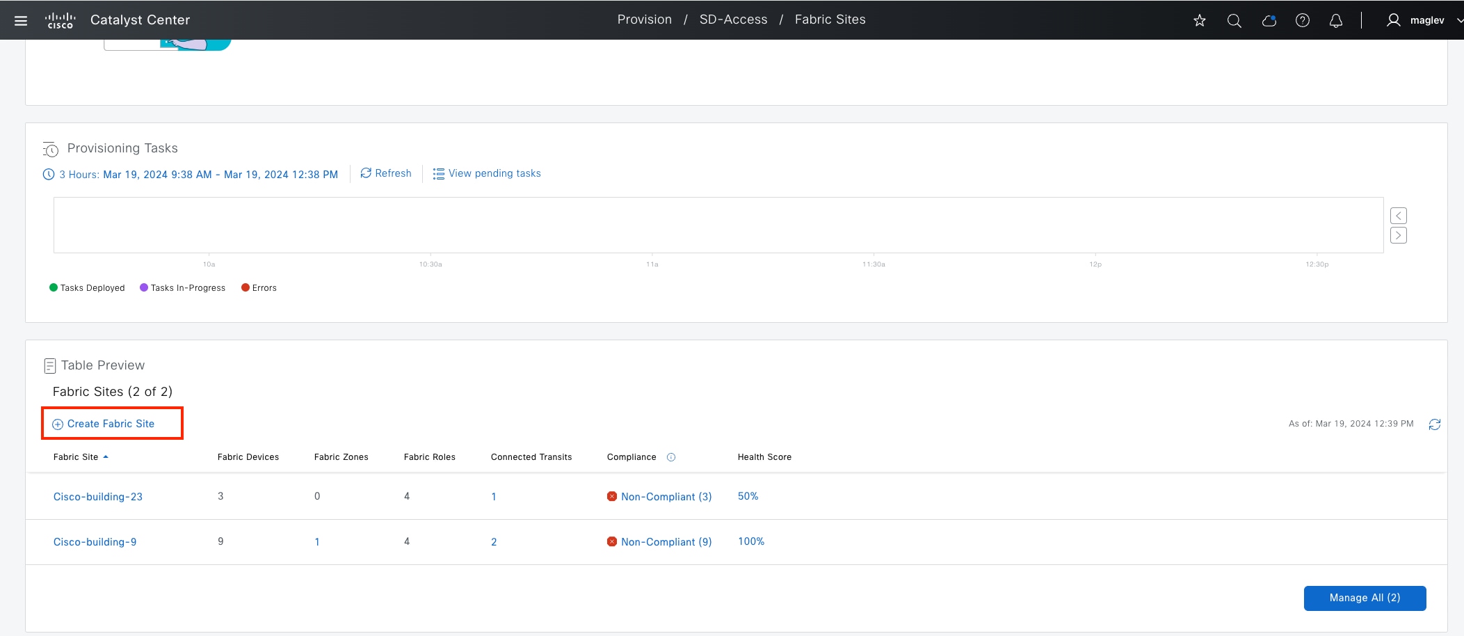
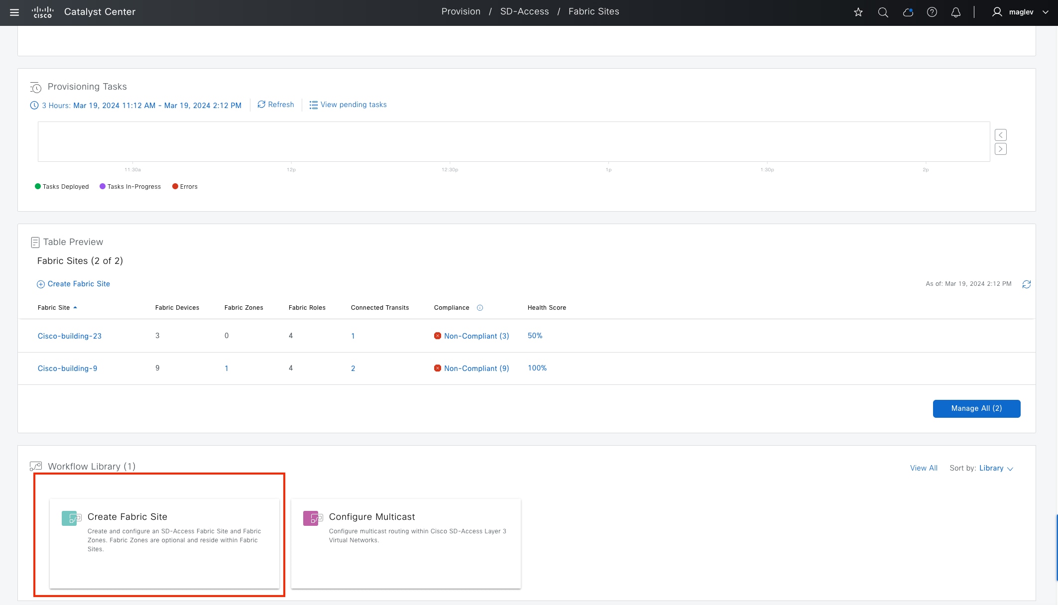
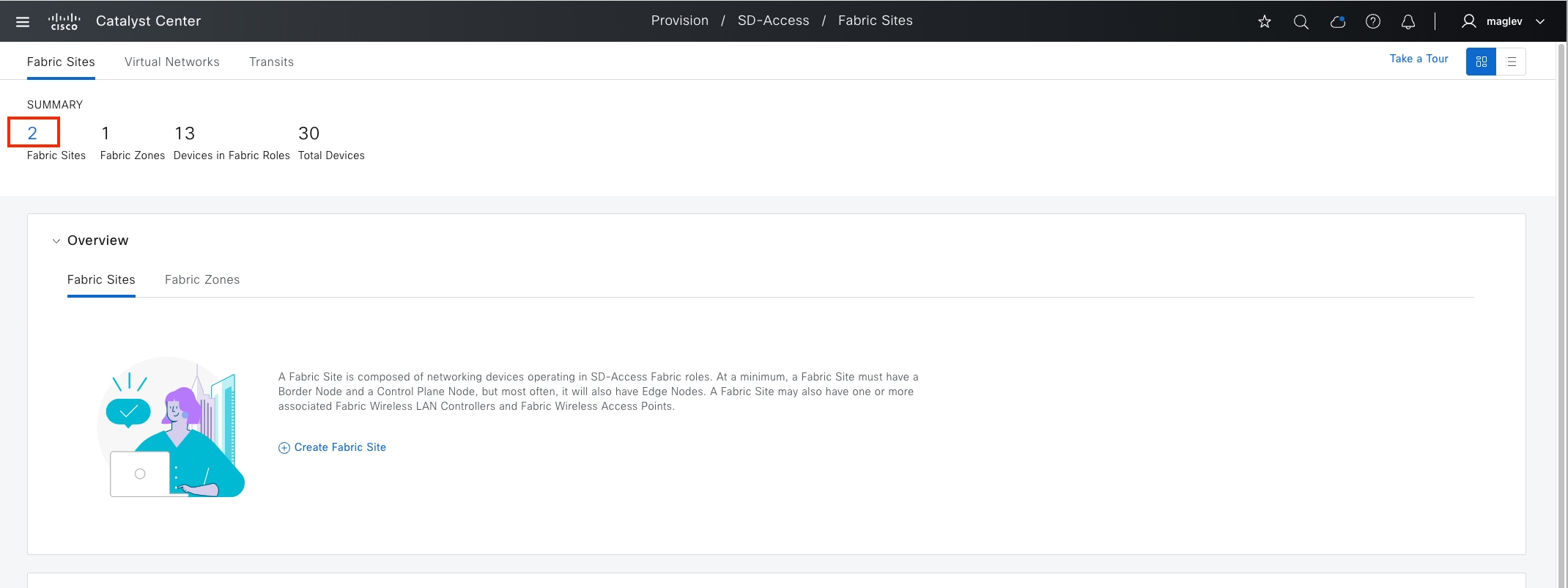
● If Catalyst Center already has other fabric sites configured, from the Fabric Sites window, click the number under SUMMARY (our example has two fabric sites configured, so click 2.)
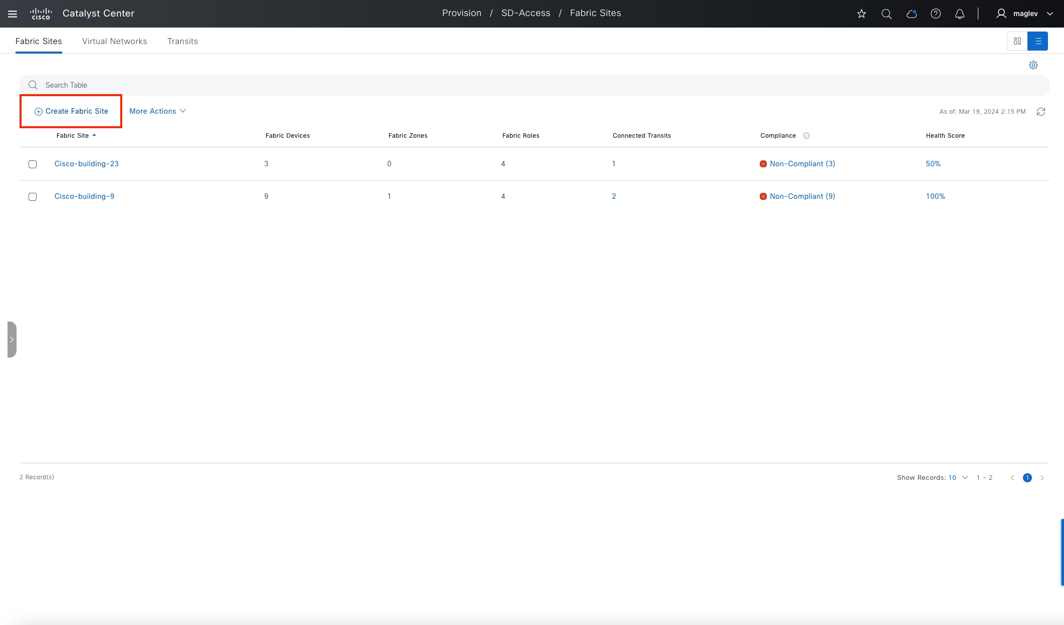
● In the redirected window, click Create Fabric Site.
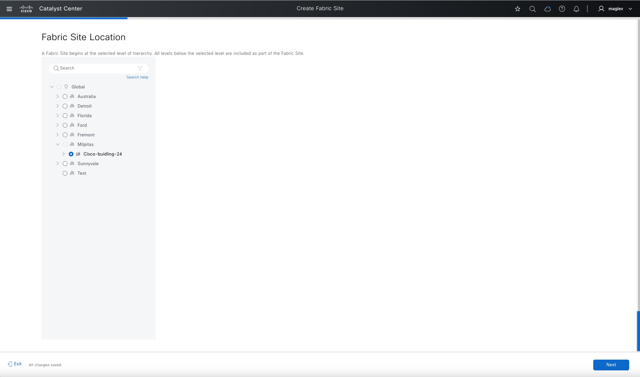
Step 2. Go through the workflow to configure the fabric on Cisco-building-24.
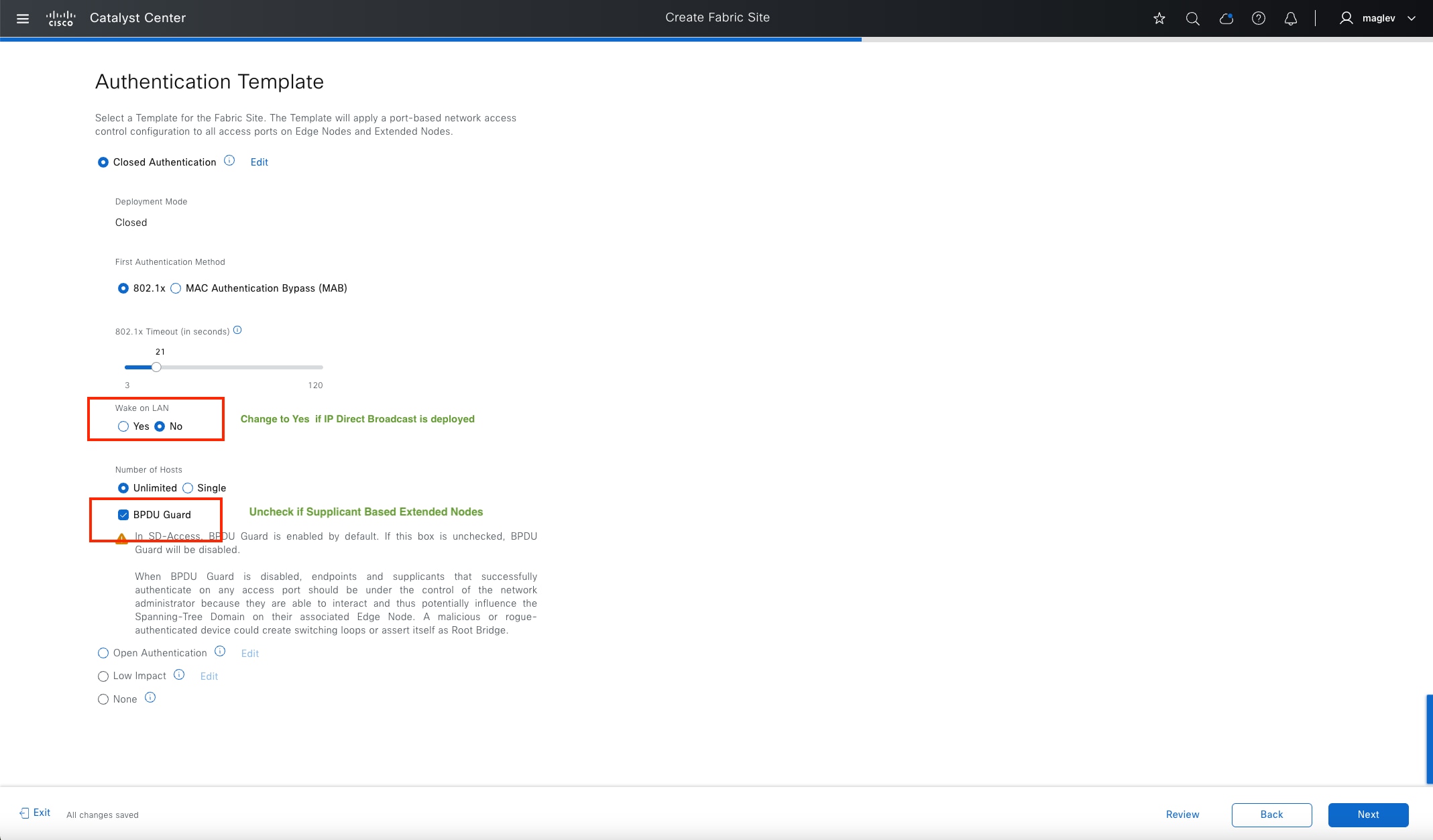
A site-level authentication template is required. Configurations in a site-level authentication template push to all the access ports on edge nodes (including FiaB) and extended nodes. Supported Catalyst Center authentication templates include:
● Closed Authentication: Network access requires full 802.1x authentication
● Open Authentication: Temporary access is granted (for example: PXE, DHCP) before 802.1x authentication
● Low Impact: MAB authentication
● None: No authentication is required for network access
Parameters in Closed Authentication, Open Authentication, and Low Impact can be modified. Parameter modification in Closed Authentication is required for certain Cisco SD-Access features, such as IP Direct Broadcast and supplicant-based extended node (SBEN). The site-level authentication template and the parameters can be changed later in day-n operations (see Cisco SD-Access network day-n operations).
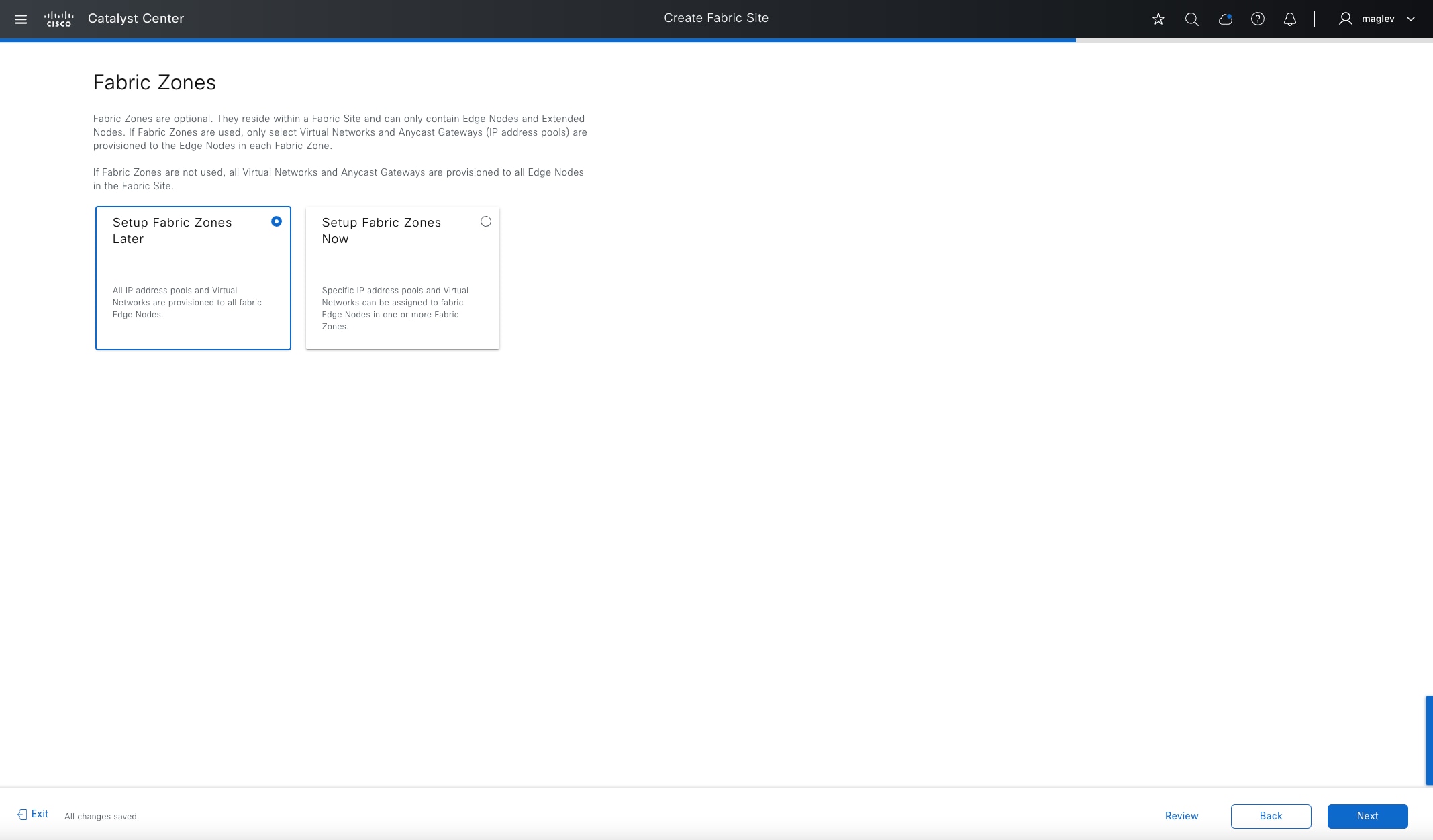
A fabric zone can be configured in the same workflow for creating a fabric site or separately later (explained in Procedure 2).
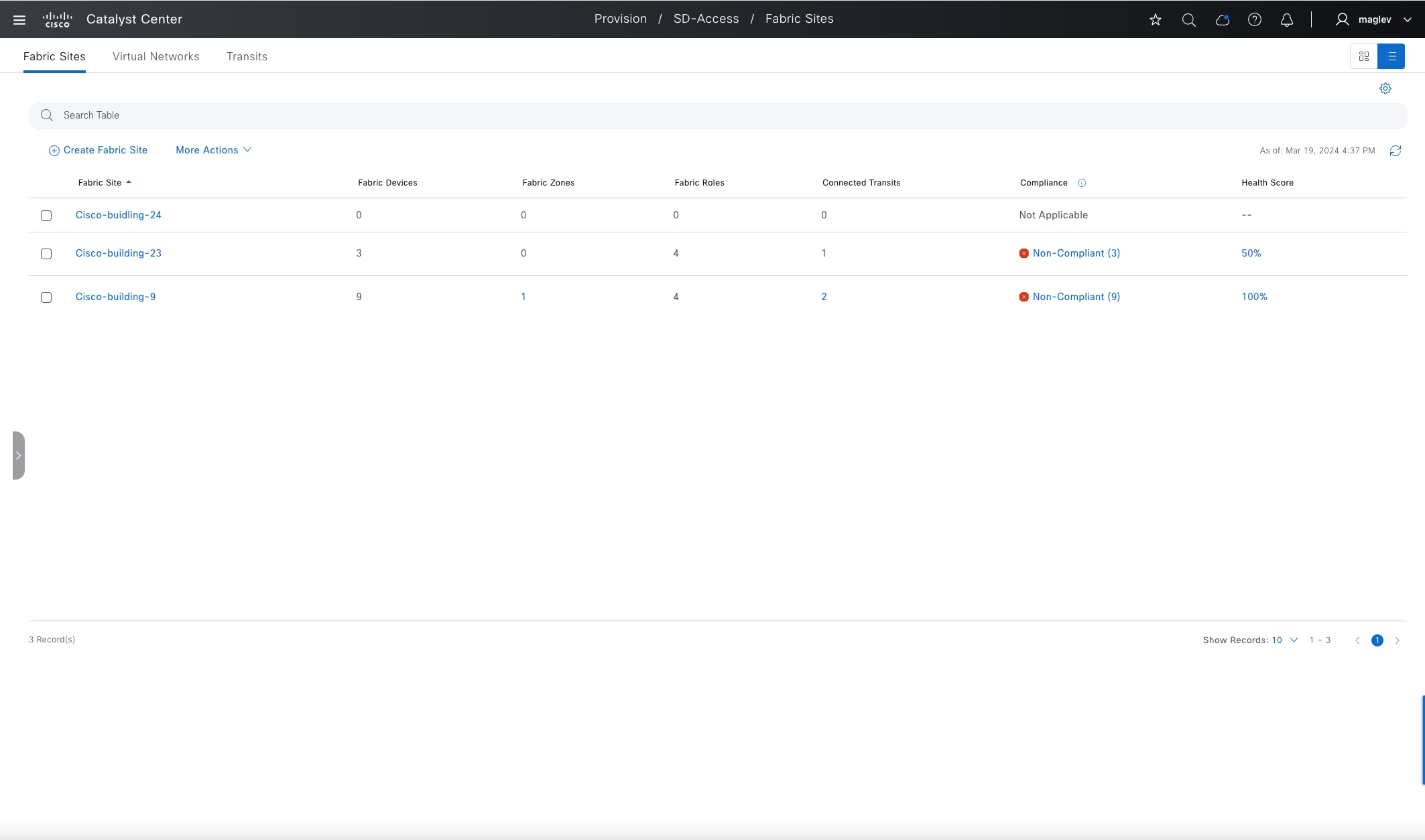
Enabling a fabric does not push any configuration to devices. After submitting the task, Cisco-building-24 is officially a fabric site.
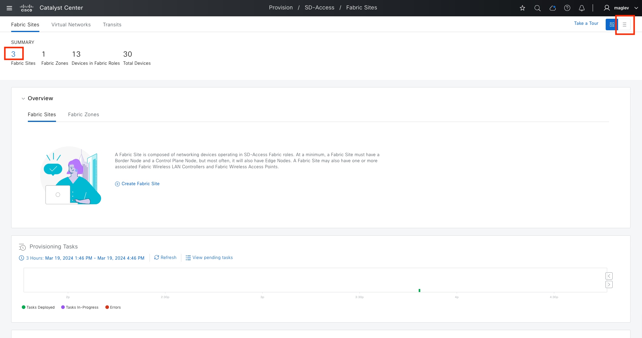
Procedure 2. Configure a fabric zone
A fabric zone can be configured together with a fabric site, or it can be configured later with and without fabric devices. In the site hierarchy, Cisco-building-24 is configured as a fabric site. A fabric zone can be enabled on a lower level, such as Floor‑1 and Floor‑2.
Step 1. From the top-left corner, click the menu icon and choose Provision > Fabric Sites.
Step 2. In the default Summary view window, click 3 to go to the fabric site table view. Alternatively, click the table view icon in the top right.
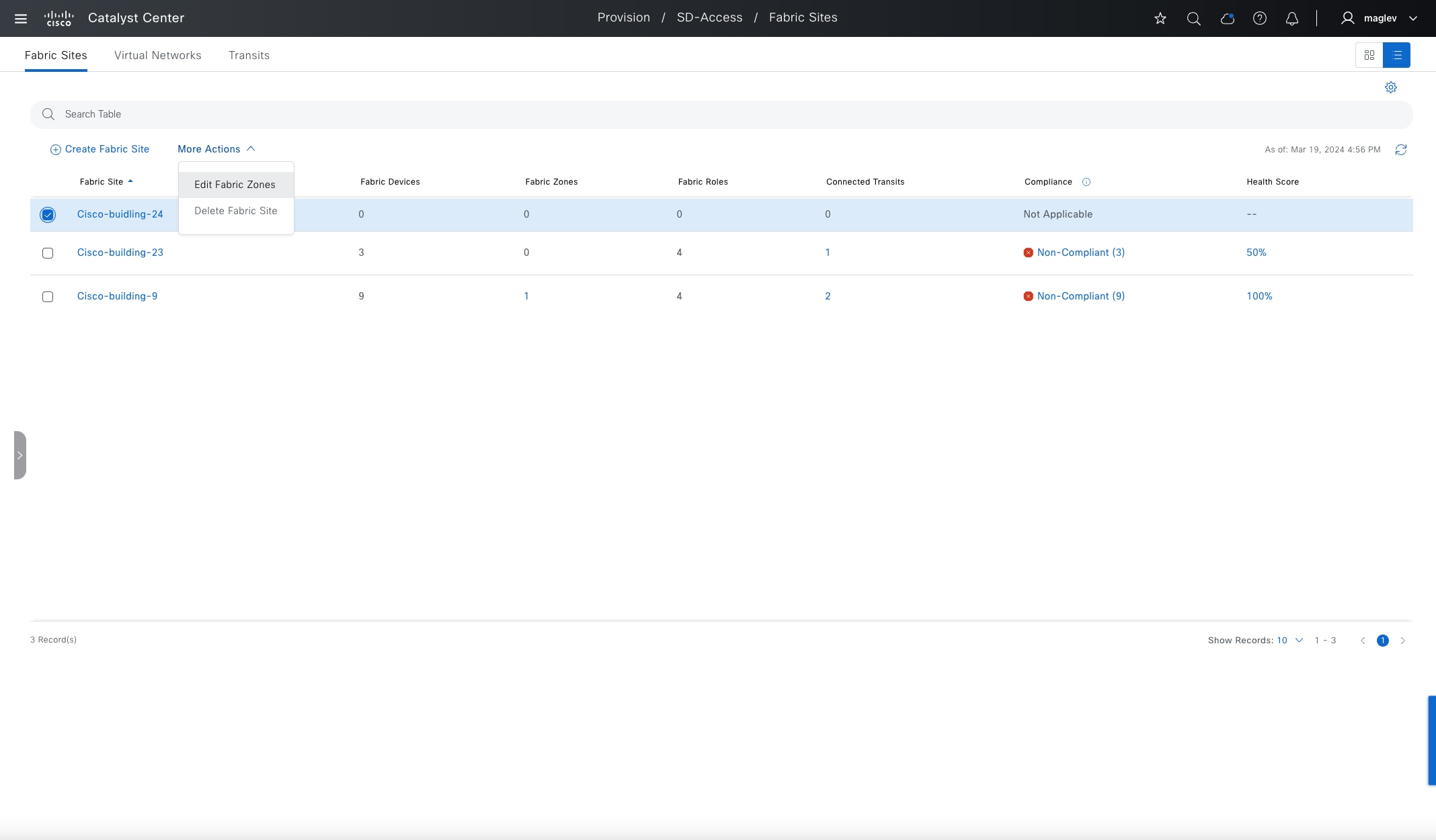
Step 3. In the table view, click Cisco-building-24 then choose More Actions > Edit Fabric Zones.
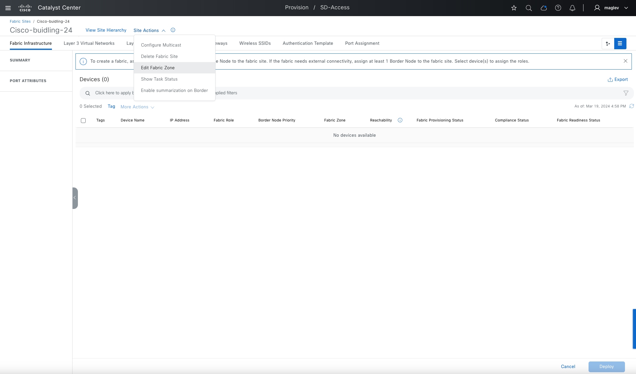
Step 4. Optionally, choose Cisco-building-24 > Site Actions > Edit Fabric Zone.
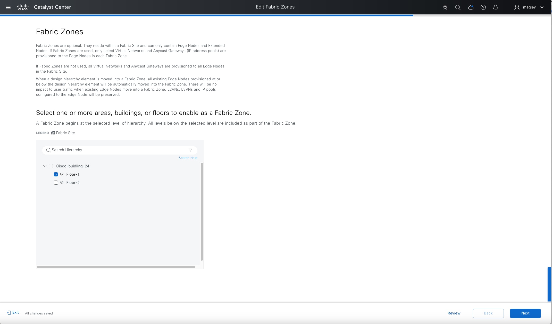
Step 5. In the Fabric Zone window, configure Floor-1.
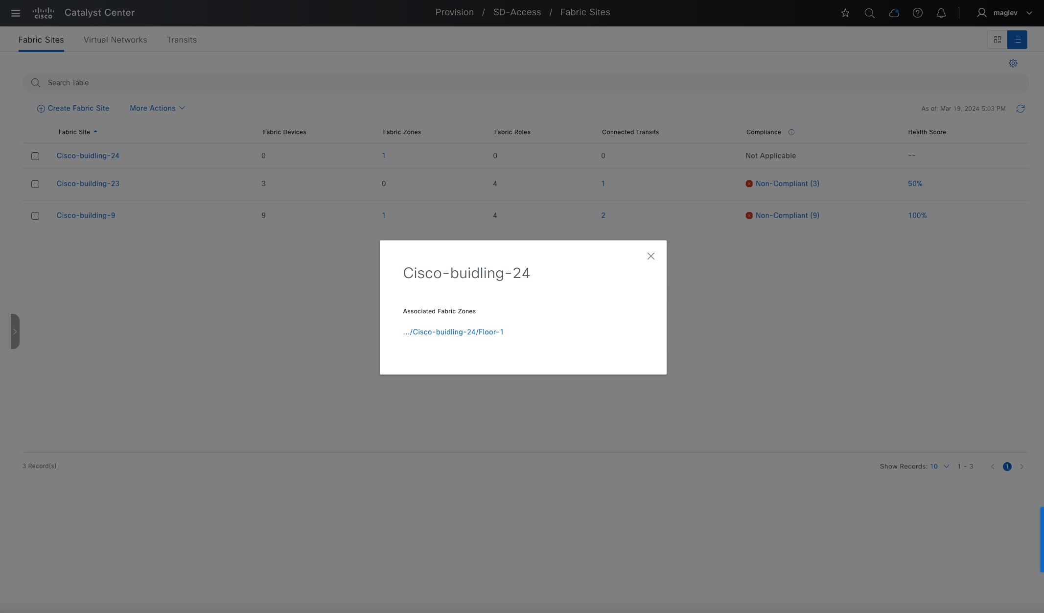
Step 6. Complete the workflow and go back to the table view.
Step 7. For Cisco-building-24, choose Fabric Zones > 1 to see the details.
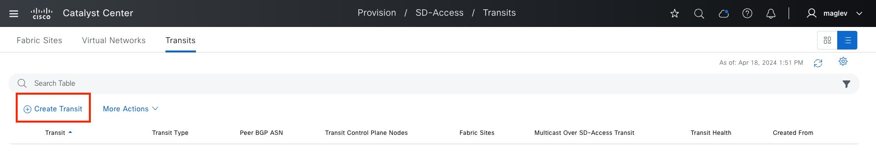
A transit network connects two or more fabric sites with each other or connects the fabric site with external networks; internet, data center, and so on. Types of transit networks include:
● IP transit:
Uses a regular IP network to connect to an external network or to connect two or more fabric sites.
● SD-Access transit:
Uses LISP with VXLAN encapsulation to connect fabric sites. Using Cisco SD-Access transit, an end‑to‑end policy plane is maintained using SGT group tags.
Procedure 1. Create Cisco SD-Access transits
Transit control plane nodes
The transit control plane nodes track all aggregate routes for the fabric domain and associate these routes to fabric sites. When traffic from an endpoint in one site needs to send traffic to an endpoint in another site, the transit control plane node is queried to determine to which site’s border node this traffic should be sent. The role of transit control plane nodes is to learn which prefixes are associated with each fabric site and to direct traffic to these sites across the Cisco SD-Access transit using control-plane signaling. Up to four Transit control plane nodes are supported.
Transit control plane deployment location
The transit control plane nodes do not have to be physically deployed in the Transit Area, nor do they need to be dedicated to their own fabric site, although common topology documentation often represents them in this way. For the prescriptive configuration in this guide, a Catalyst 9500 switch is used as the transit control plane node.
While accessible only using the Transit Area, the transit node does not act as a physical transit hop in the data packet forwarding path. Instead, it functions similarly to a DNS server where it is queried for information, even though data packets do not transit through them.
To use devices as control plane nodes, the devices need to be managed and provisioned. See Discover and provision devices.
Step 1. From the top-left corner, click the menu icon and choose Provision > Transits, click the table view icon in the top right, click the Transits tab, then click Create Transits to start the workflow.
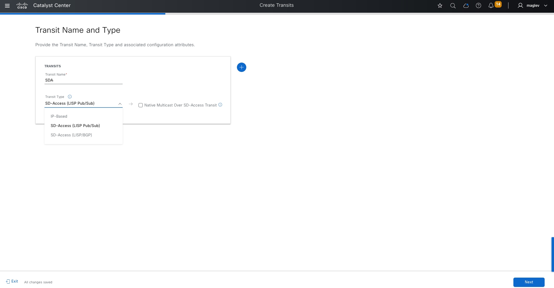
Step 2. Type SDA for the Transit Name field, choose Transit Type > SD-Access (LISP Pub/Sub) then click Next.
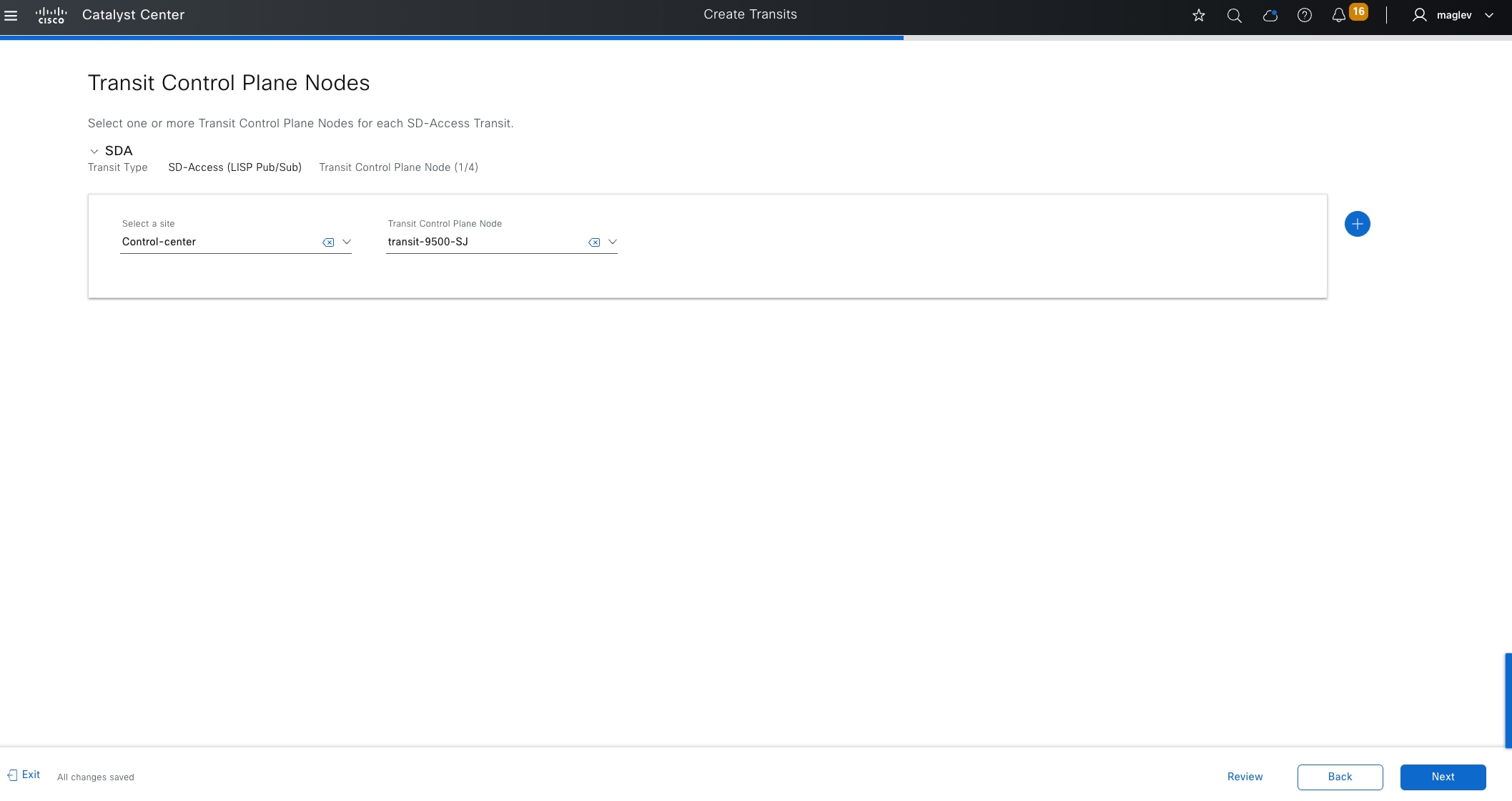
Tech tip:
1. Native multicast over Cisco SD-Access transit can be enabled in day-n operation later, if required.
2. The Cisco SD-Access transit type must be the same as the fabric site type.
3. Connecting LISP Pub/Sub and LISP/BGP sites using Cisco SD-Access transit is not supported.
Step 3. Choose the site where the Catalyst 9500 device is provisioned and select it as the Transit Control Plane Node then click Next.
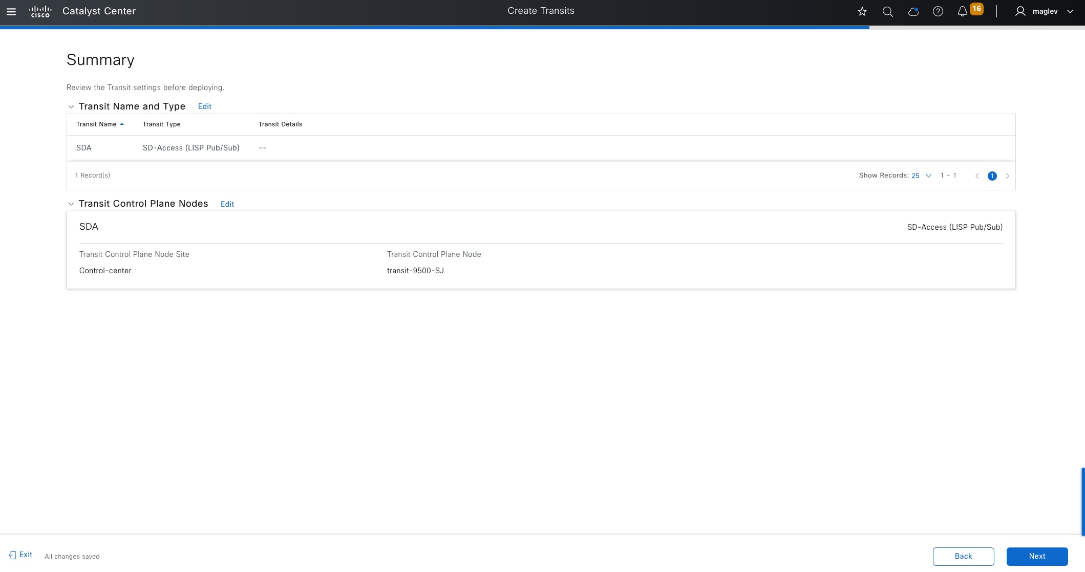
Step 4. Review the Summary window information then click Next to complete the workflow and deploy the task.
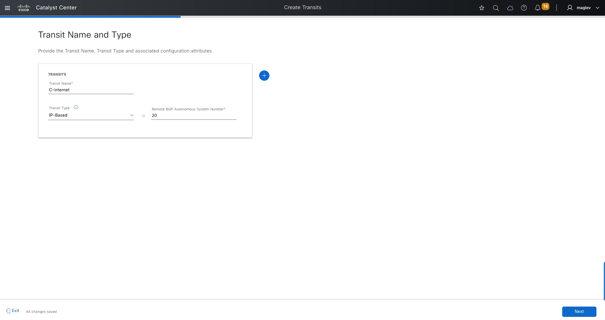
Procedure 2. Create IP transit
The IP-based transit represents the remote BGP autonomous system (AS). Normally remote BGP AS is configured in peer devices. Routes for shared services or the default route are advertised from peer devices to border devices using the BGP protocol. The local BGP AS is configured as part of the fabric border provisioning in subsequent steps.
Step 1. From the top-left corner, click the menu icon and choose Provision > Transits, click the table view icon in the top right, click the Transits tab, then click Create Transits to start the workflow.
Step 2. Type a Transit Name, choose Transit Type > IP-Based, and provide an AS number (on peer devices) then click Next.

Step 3. Review the Summary window information then click Next to complete the workflow and deploy the task.
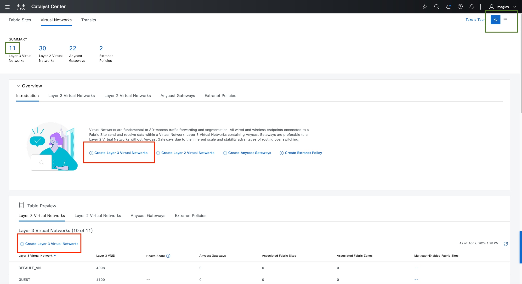
Configure VNs
The layer 3 VN and layer 2 VN can be configured from the Global level and added to a fabric site or configured directly from a fabric site.
Layer 3 VN DEFAULT_VN and INFRA_VN are created by Catalyst Center. INFRA_VN is mapped to the global routing table and used for APs and extended nodes.
When creating a layer 3 VN, a layer 2 VN is also created. A pure layer 2 VN can be created using the Catalyst Center workflow if layer 3 is not required.
In this section, layer 3 VN VN_Guest and VN_EMP are created and added to Cisco-building-24 along with INFRA_VN. A pure layer 2 VN Guest with a VLAN 4000 configuration is created and added to Cisco‑building-24.
Procedure 1. Configure a layer 3 VN and add the layer 3 VN to a fabric site and fabric zone
Step 1. From the top-left corner, click the menu icon and choose Provision > Virtual Networks.
Step 2. Click Create Layer 3 Virtual Networks, as shown in the figure. Alternatively:
● Click the number under SUMMARY to be redirected to the table view.
● At the top right, click the table view icon button.
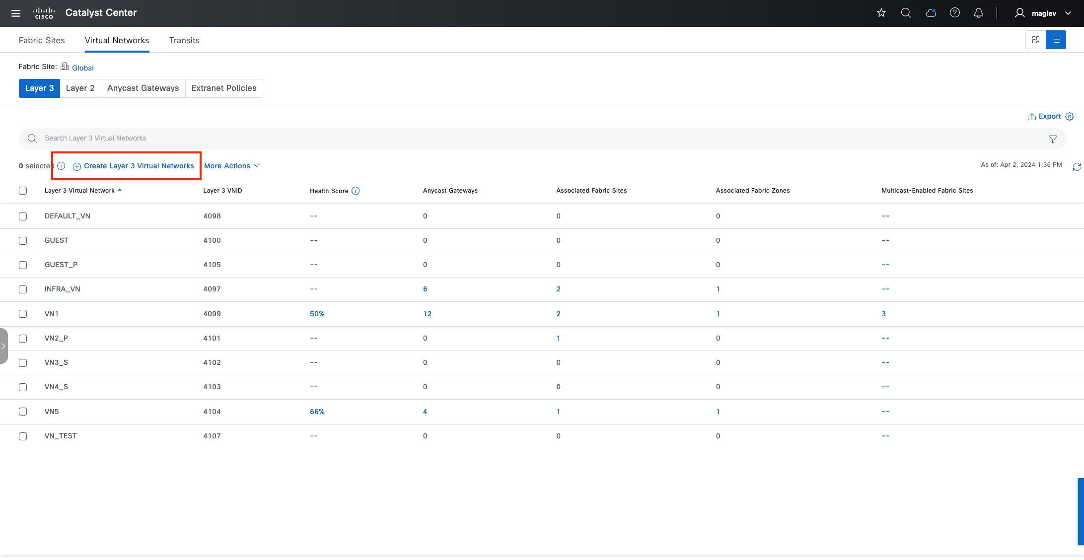
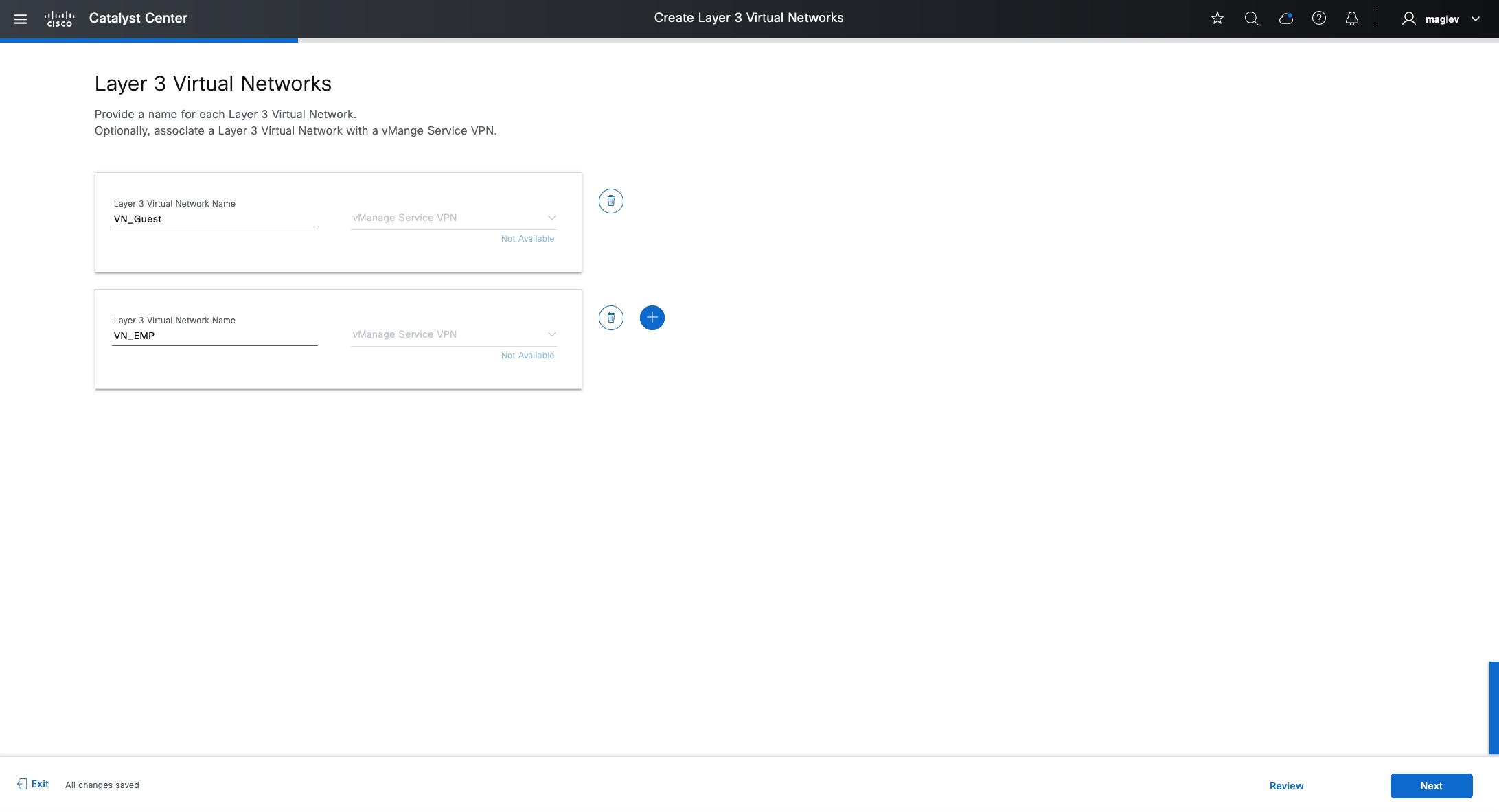
Step 3. Create VN_Guest and VN_EMP and click Next.
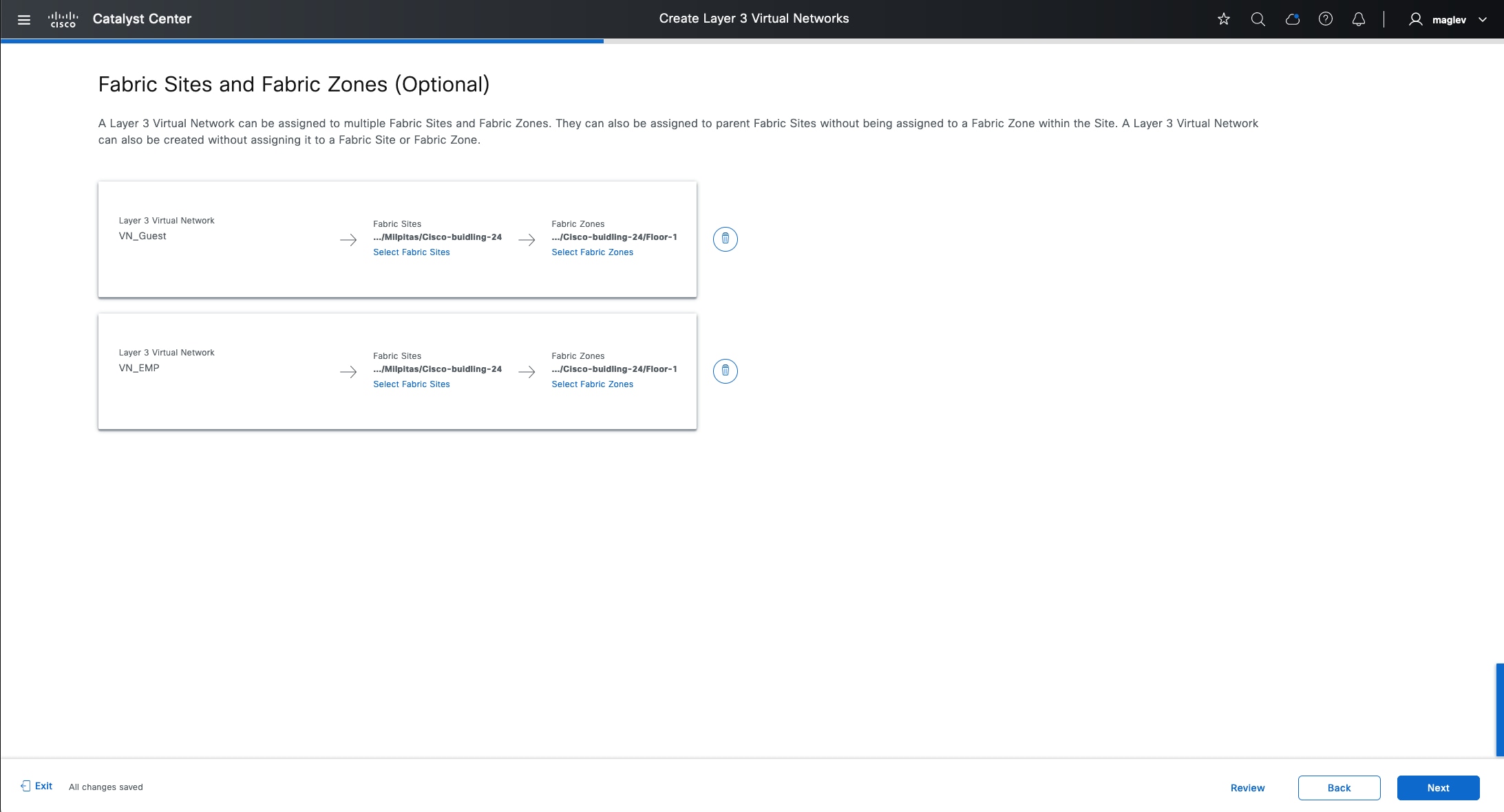
Step 4. In the Fabric Site and Fabric Zone (Optional) window, add Cisco-building-24 and Floor-1 then click Next to complete the workflow.
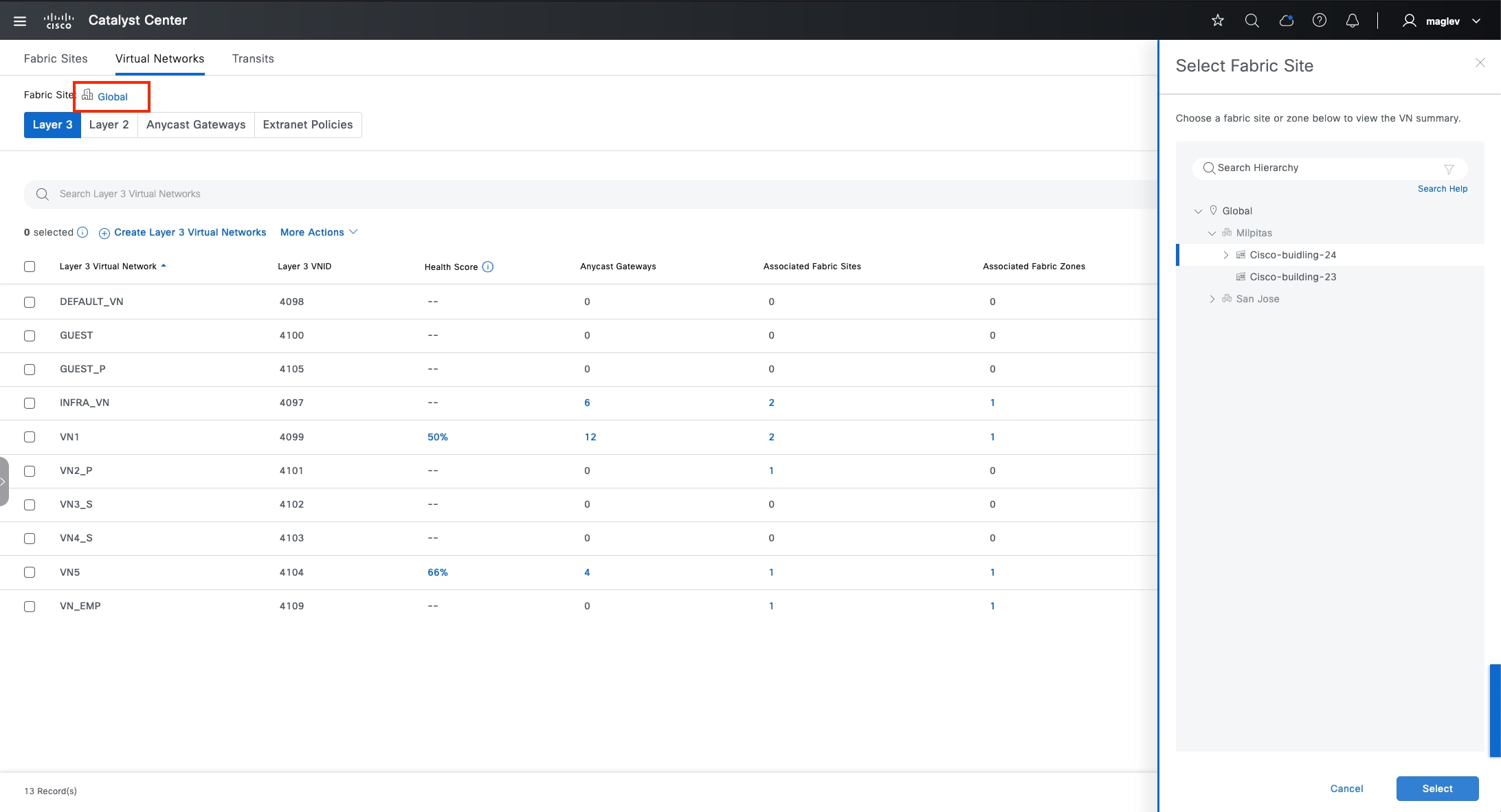
Tech tip: Creating a VN does not push configurations to devices.
Step 5. To add INFRA_VN to the fabric site Cisco-building-24 and the fabric zone Floor-1, click Global to switch to Cisco-building-24.
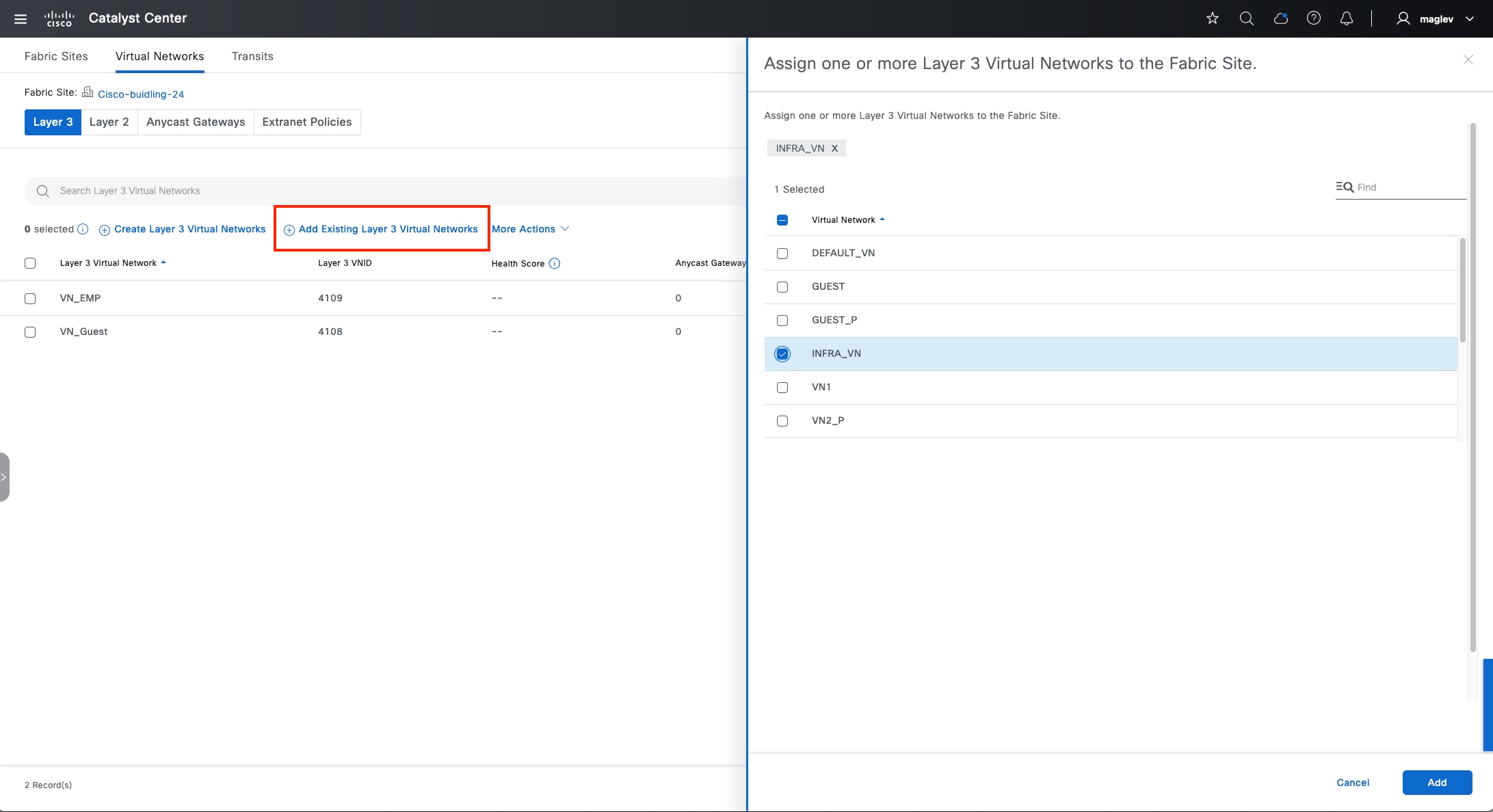
Step 6. Choose Add Existing layer 3 Virtual Networks > INFRA_VN and finish the workflow.
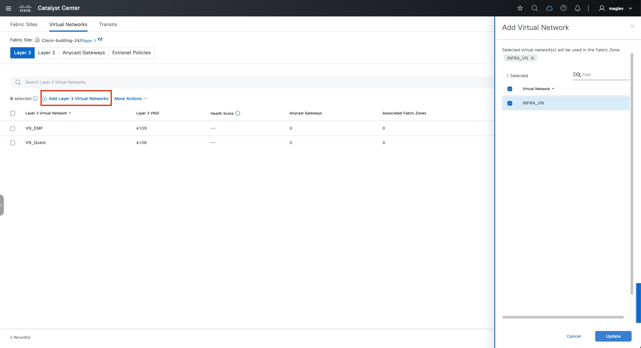
Step 7. Switch to the fabric zone Floor-1 and check the INFRA_VN check box.
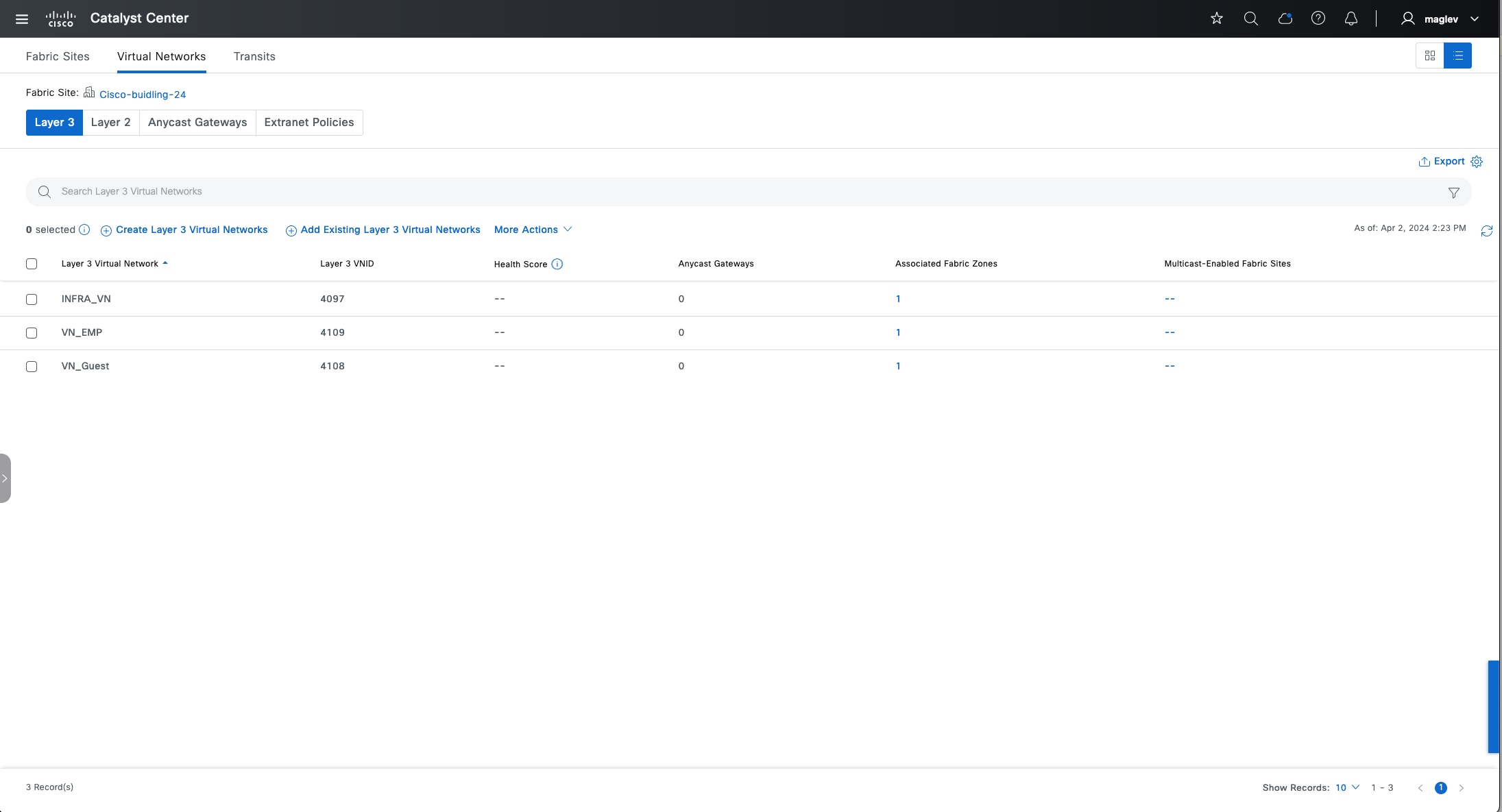
INFRA_VN, VN_EMP and VN_Guest are added to the fabric site and the fabric zone.
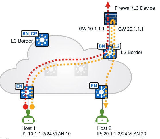
Procedure 2. Configure a layer 2 VN and add a layer 2 VN to a fabric site and a fabric zone
When creating an anycast gateway in a layer 3 VN, by default a layer 2 VN is also created. Catalyst Center also supports layer 2 only VN, which is mainly used when a gateway is outside the fabric.
● A gateway for the subnets can be a firewall or a layer 3 device connected to a layer 2 border. Traffic towards an enterprise WAN passes through a layer 2 border.
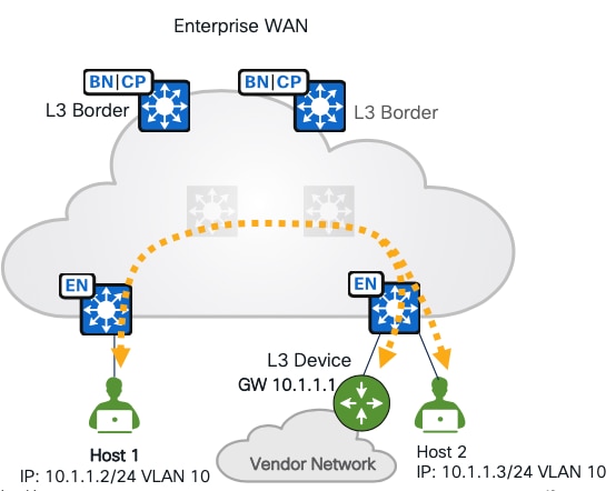
● A gateway is outside the fabric, but on a layer 3 device, it is connected to the fabric edges.
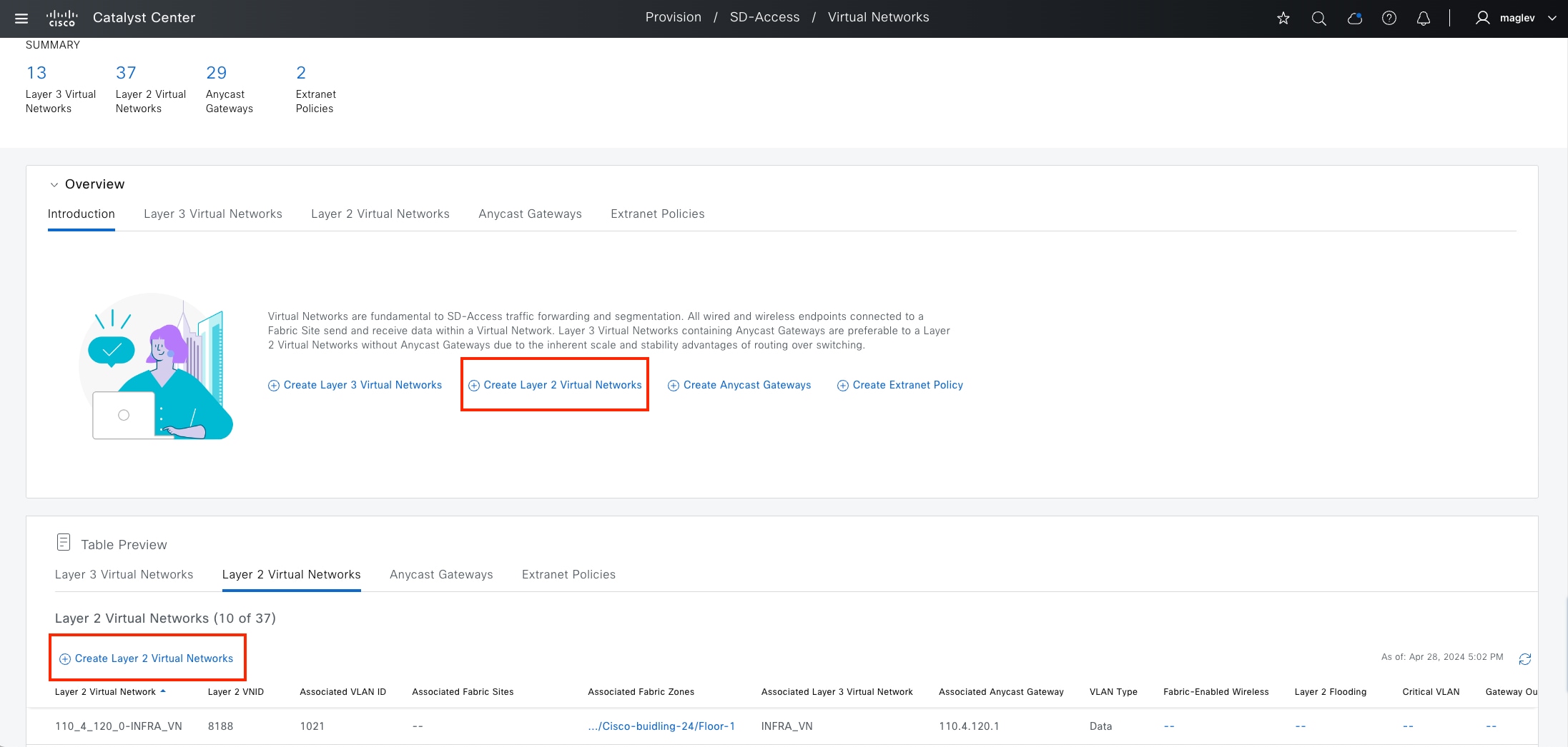
To create a layer 2 only VN:
Step 1. From the top-left corner, click the menu icon and choose Provision > Virtual Networks. By default, you start in the Summary view. Similar to creating a layer 3 VN, in the default window, there are several places to Create Layer 2 Virtual Networks.
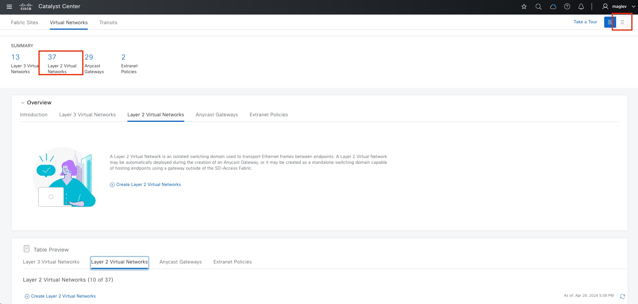
● Alternatively, click Create Layer 2 Virtual Networks, as shown in the figure, or click the number under SUMMARY to be redirected to the table view, or change to table view from the top right icon button.
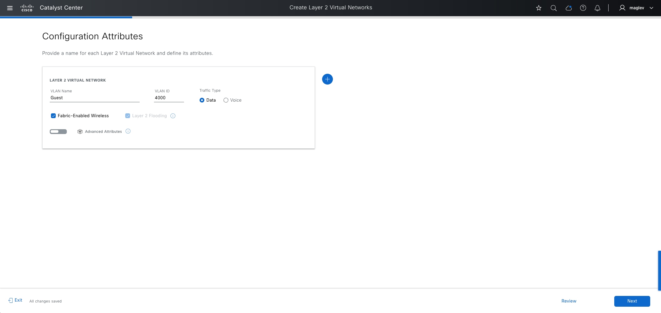
Step 2. In the table view, click Create Layer 2 Virtual Networks and enter the required fields:
| Fields |
Value |
| VLAN Name |
Guest |
| VLAN ID |
4,000 |
| Traffic Type |
Data |
Step 3. To onboard wireless clients, also check the Fabric-Enabled Wireless check box.
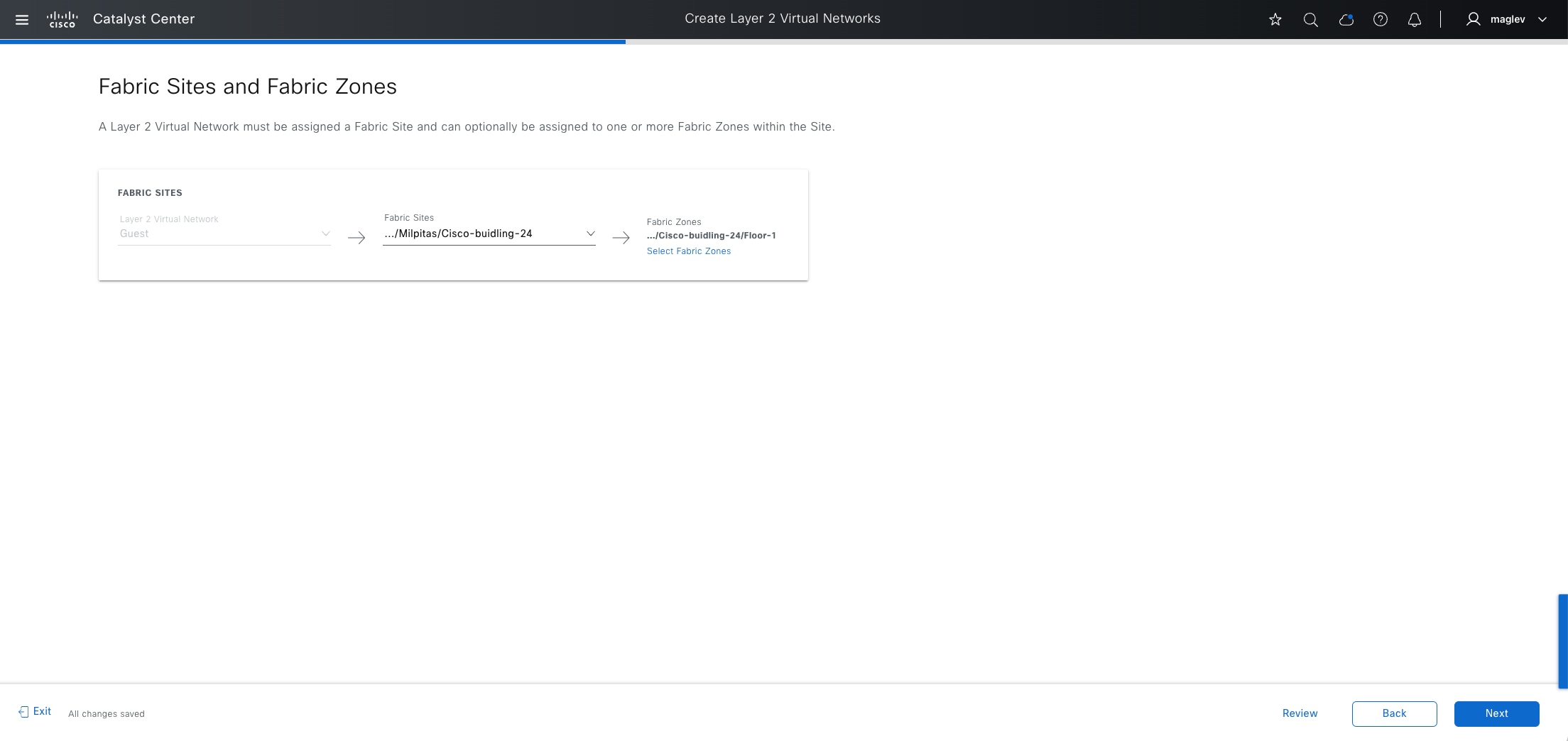
Step 4. In the Advanced Attributes dialog, check the Wireless Bridge VM check box to see if the clients are there.
Step 5. Assign to Cisco-building-24 and zone Floor-1 and complete the workflow to deploy the task.
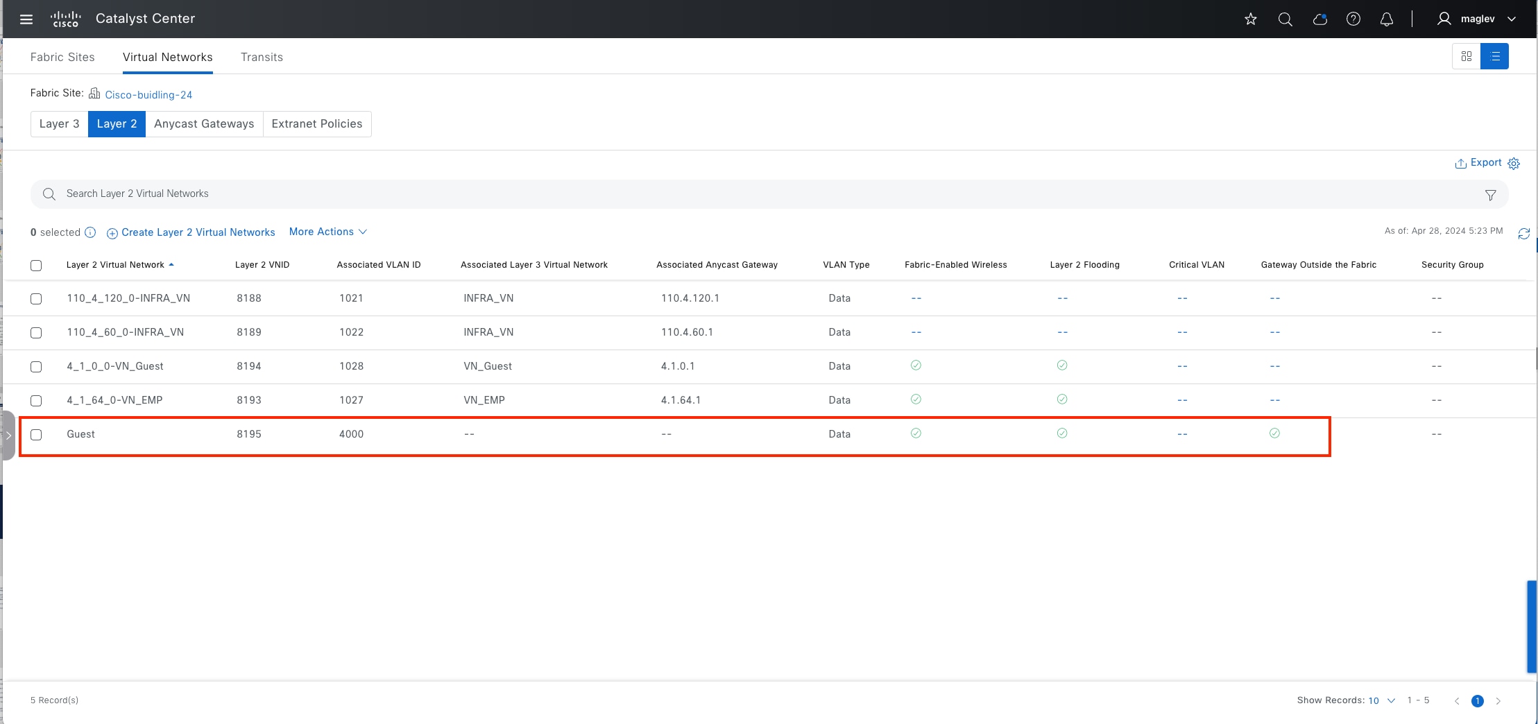
Step 6. Confirm that the Guest VN is created only in Layer 2.
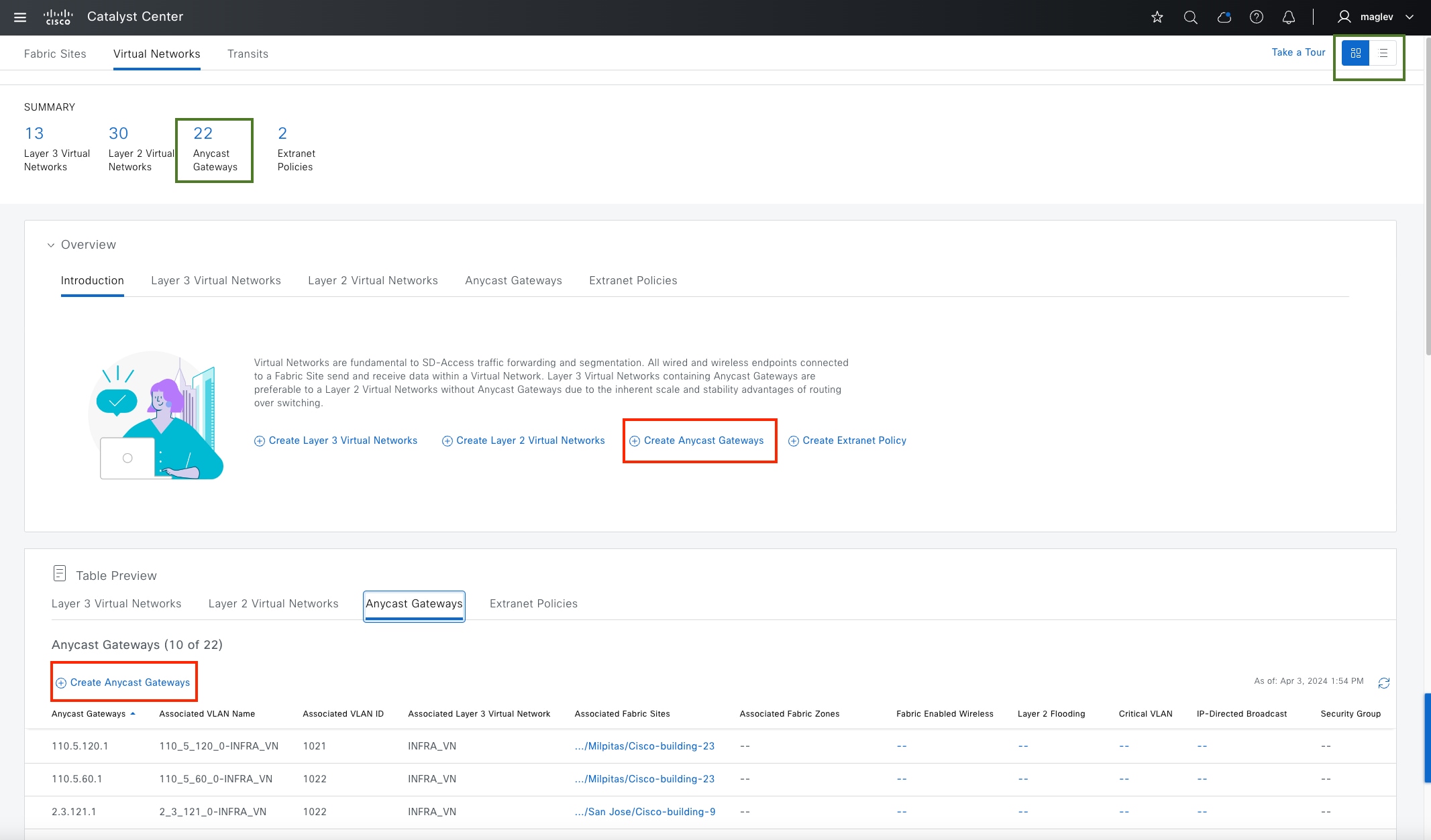
Create an anycast gateway and add it to a fabric site and fabric zones
Creating an anycast gateway is the process of associating an IP address pool to a VN. IP address pools provide a default gateway and basic IP services for endpoints. This default gateway is an anycast gateway. An anycast gateway is analogous to a first hop switched virtual interface in a traditional network that does not use Cisco SD-Access.
Adding an anycast gateway can be done on the Global level or on the site and zone level.
In this section, anycast gateway for an AP, extended nodes in INFRA_VN, and an anycast gateway in the custom VN VN_Guest and VN_EMP are added in the Cisco-building-24 site and zone Floor-1.
Procedure 1. Add an anycast gateway in INFRA_VN
Step 1. From the top-left corner, click the menu icon and choose Provision > Virtual Networks. By default, the landing window is the Summary view.
Anycast gateway can be created from the Overview and Table Preview sections. It can also be created from the table view.
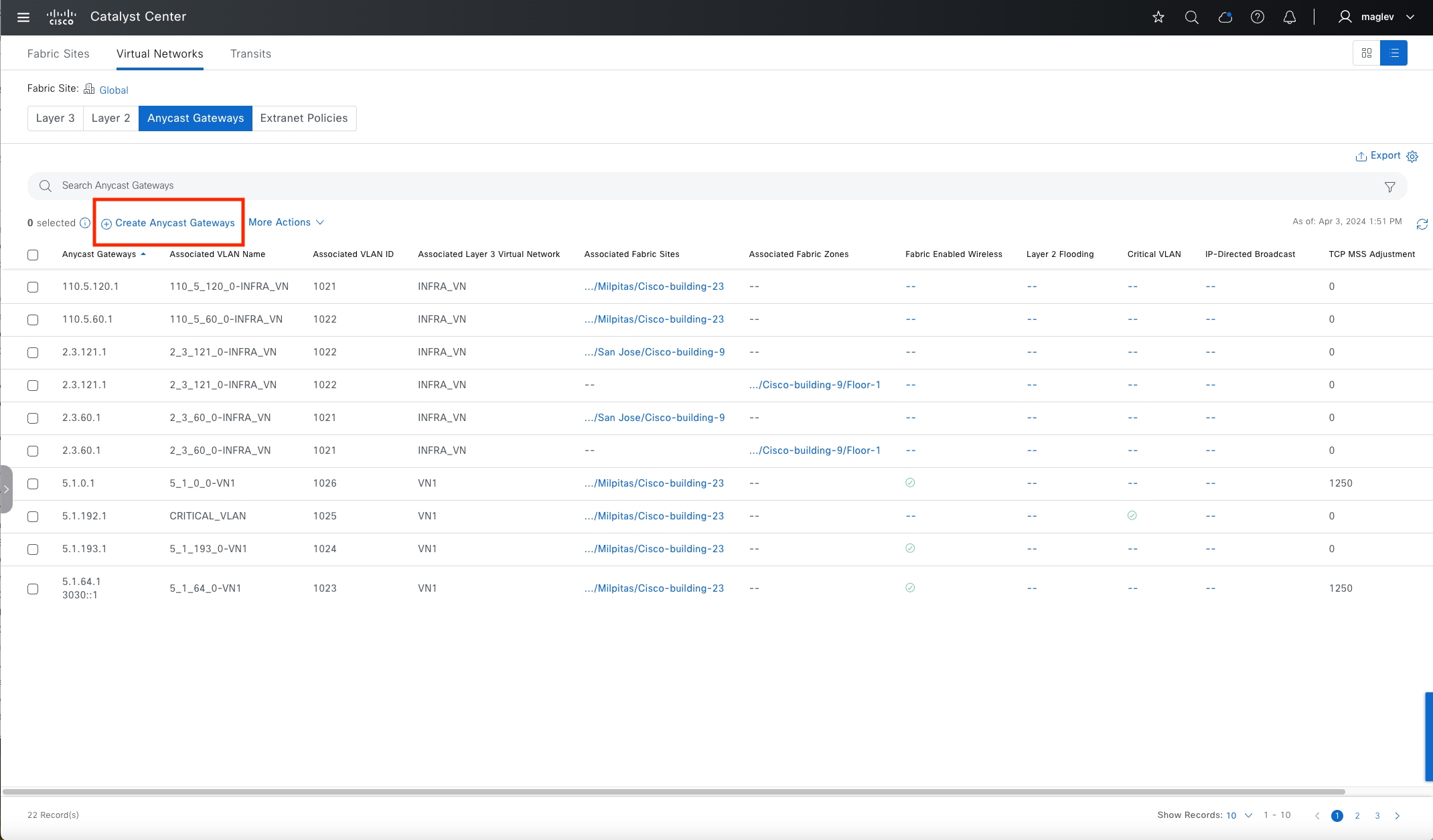
Step 2. Click the top right icon button to switch to the table view layout then click Create Anycast Gateways.
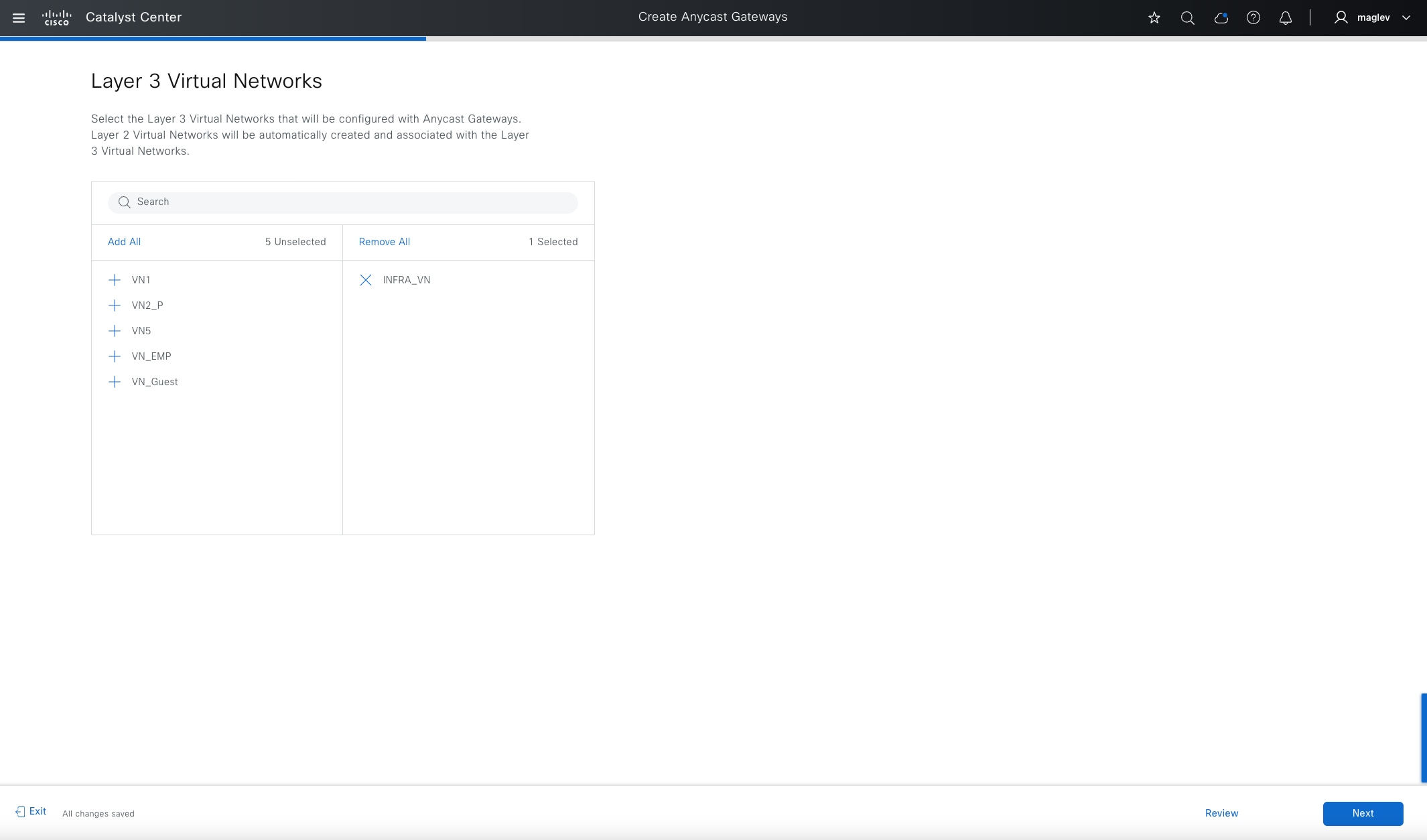
Step 3. Start the Create Anycast Gateways workflow and select INFRA_VN.
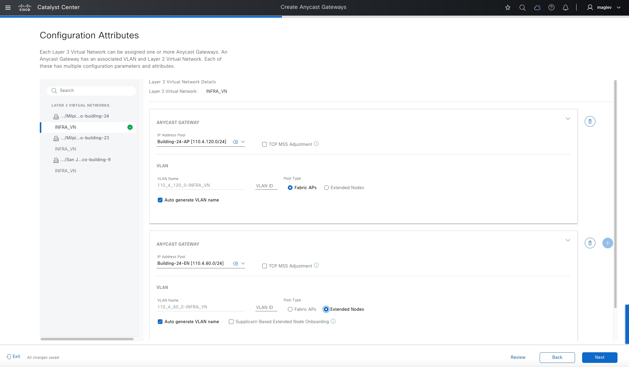
Step 4. Add the IP address pools created in Step 2 then for Cisco Building-24 select Fabric APs and Extended Nodes for Pool Type (select from the left pane).
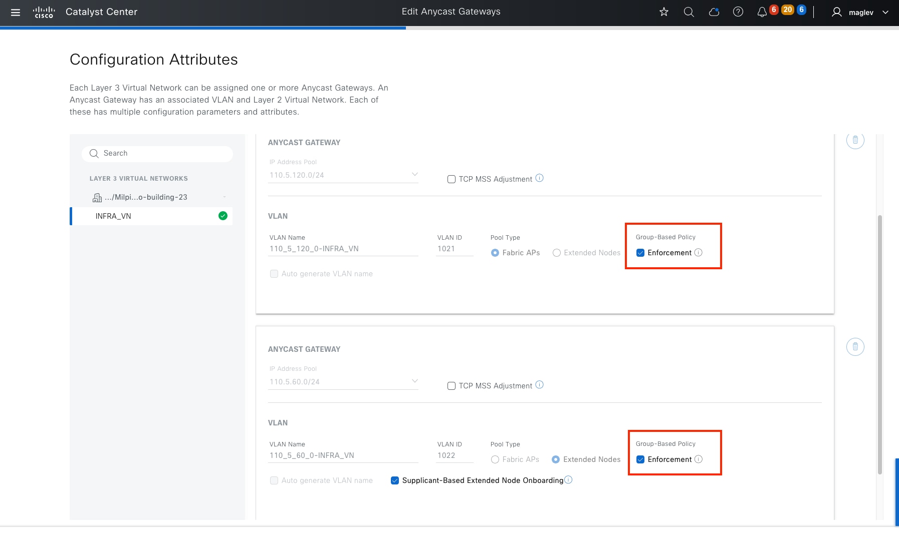
Note:
1. Pool Type, VLAN name cannot be changed after an anycast gateway is created. TCP MSS adjustment, Supplicant-Based Extended Node Onboarding can be added and modified later in day-n operations.
2. If the AP and EN pools were added in Catalyst Center before the 2.3.7.6 release, after upgrading to 2.3.7.6, the Enforcement option is available for these two pools. If you decide to uncheck this option, ‘no cts role-based enforcement VLAN AP-VLAN/EN-VLAN’ pushes to all fabric access devices, such as fabric edges, policy extended nodes, and supplicant extended nodes. After this option is unchecked and the configuration is deployed, this option will not be visible. This option is not visible for APs and EN pools added in the 2.3.7.6 and later release. Catalyst Center by default disables enforcement for APs and EN pools starting from the 2.3.7.6 release.
‘cts role-bases enforcement’ is used for microsegmentation and to manage client traffic. AP and EN in INFRA_VN normally do not require policy enforcement and this configuration must be manually removed if ‘deny IP’ is the default policy for the fabric site. This option helps fabric deployments with ‘deny IP’ set as the default policy.
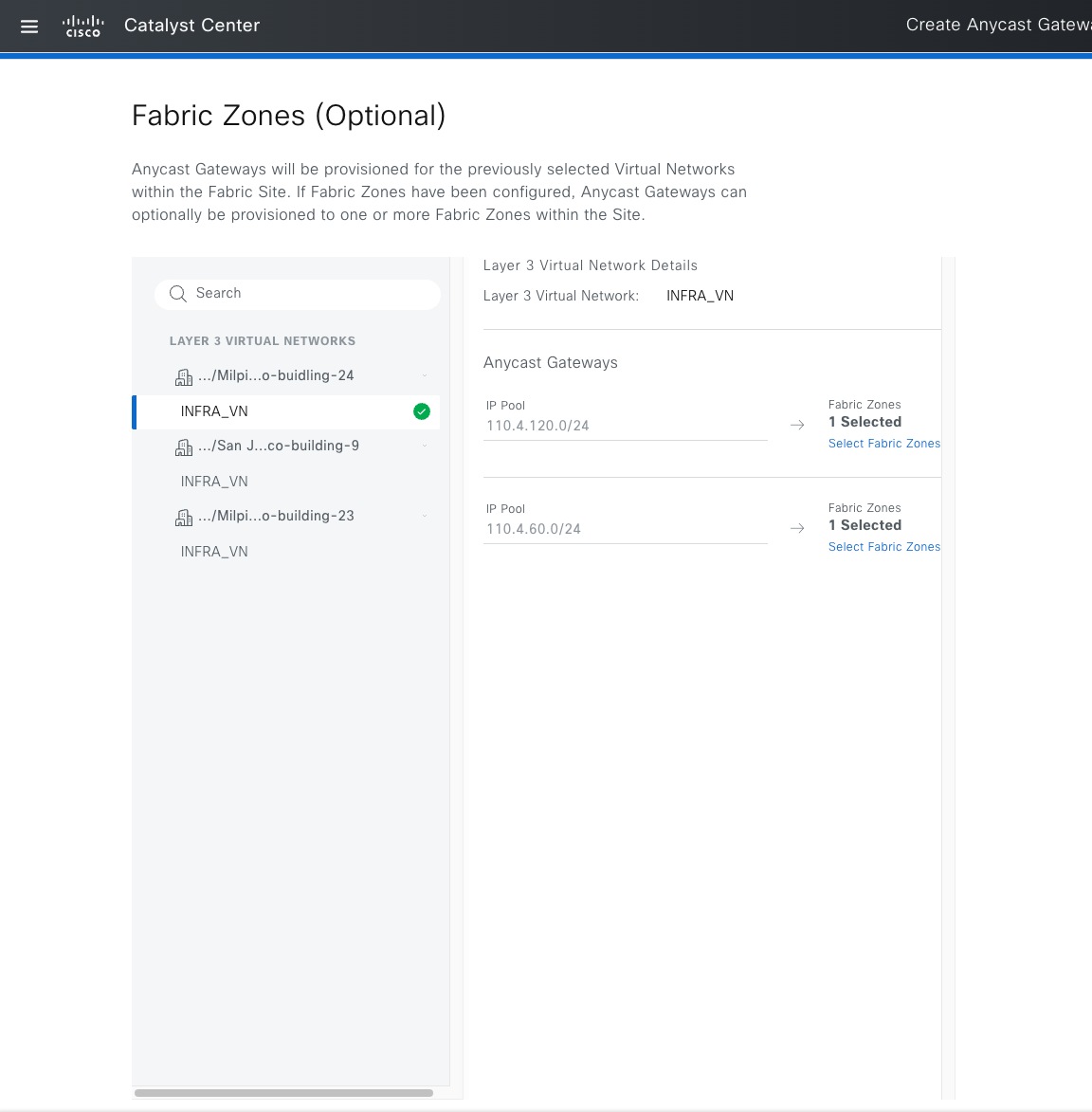
Step 5. Add to the fabric zone Floor-1.
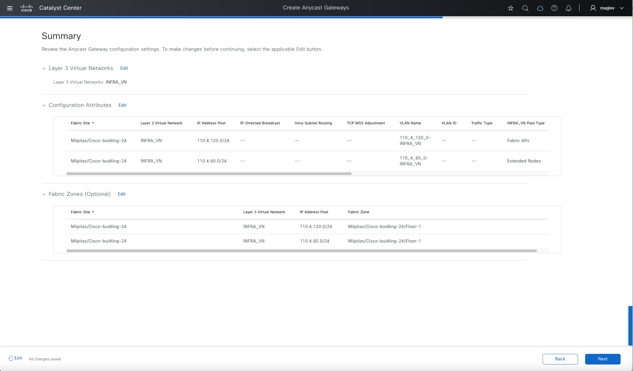
Step 6. Review the configuration information in the Summary window and deploy the task.
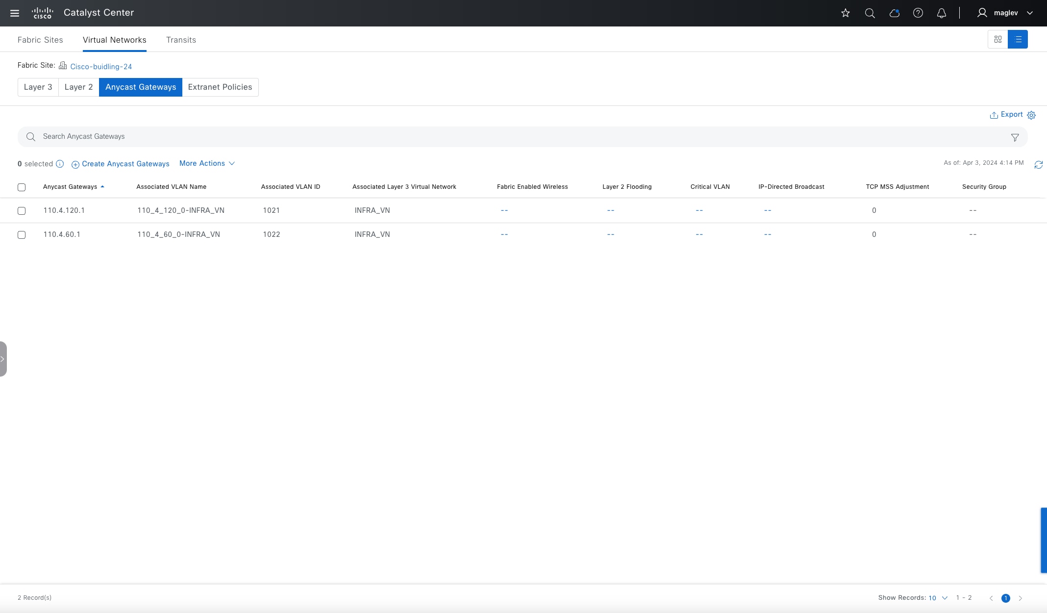
Step 7. Switch to Cisco-building-24 and click the Anycast Gateways tab and the Layer 2 tab to review the two new crated anycast gateways and layer 2 VNs.
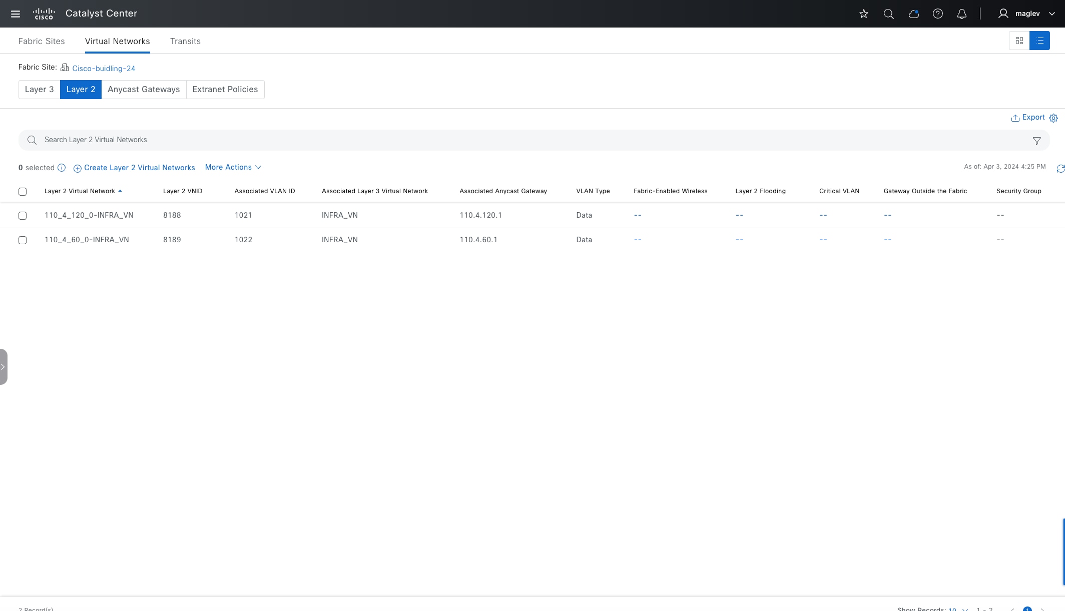
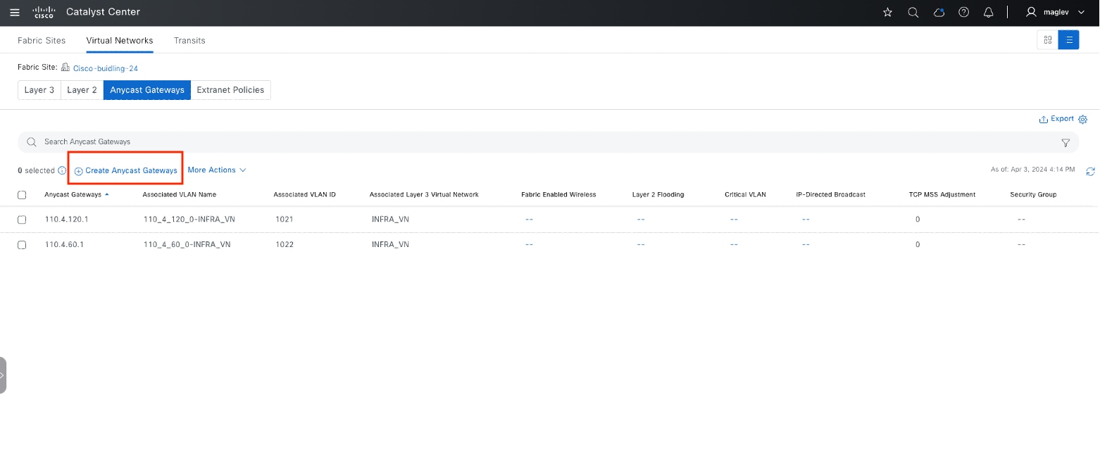
Procedure 2. Add an anycast gateway in a custom VN
The previous procedure demonstrated creating anycast gateways on a Global level. This procedure demonstrates creating anycast gateways on a site level.
Step 1. Click the Anycast Gateway tab on Cisco-building-24 then click Create Anycast Gateways to start the workflow.

Step 2. Choose both VN_EMP and VN_Guest in the workflow.

Step 3. Add IP address pools to the VNs separately. Switch between VNs from the left pane.
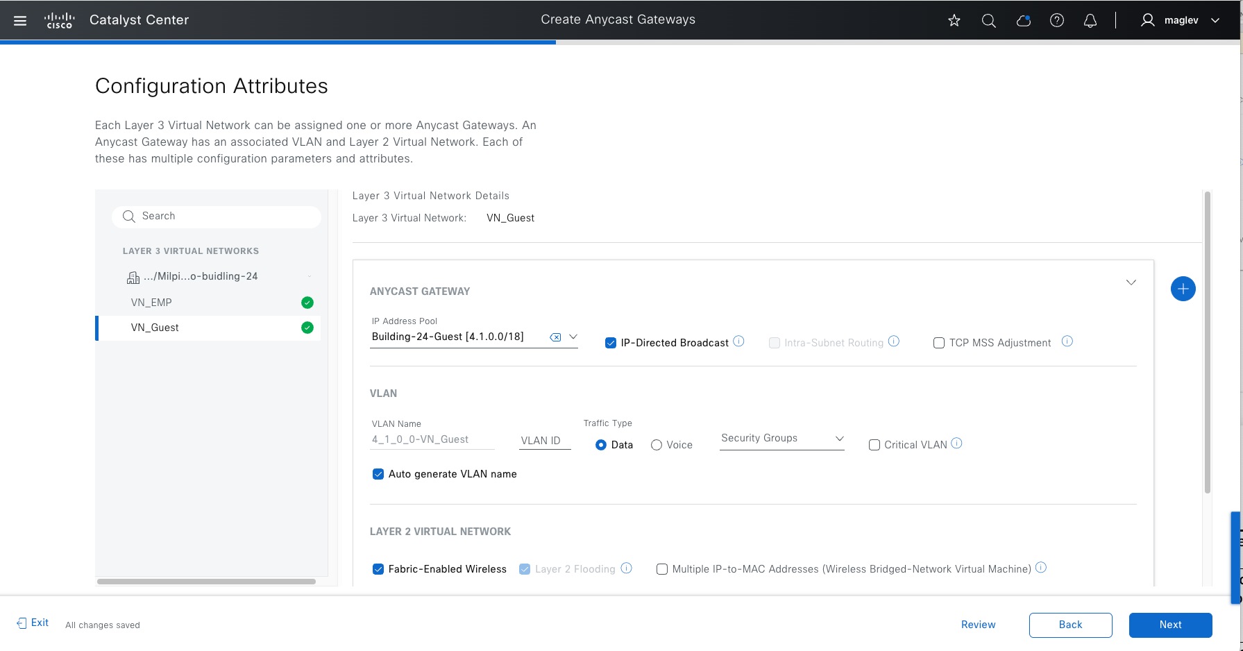
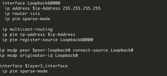
Table 20. IP pool attributes
| Attributes |
Use |
Restriction |
| IP-Directed Broadcast |
Wake on LAN magic packets (server is outside Fabric) to wake up sleeping hosts in Fabric. When enabled, the layer 2 flooding function enables automatically. WoL scenarios: 1. The source (WoL initiator) is outside the Cisco SD-Access fabric but located in the network that is connected to the fabric through layer 3 handoff and the destination is in a Cisco SD-Access subnet with IP-Directed Broadcast enabled in the same VN. 2. If source (WoL initiator) and destination (sleeping host) are both in the same subnet and same VN, for example: both are connected to Fabric Edges. This feature is not required, but layer 2 flooding is.
|
Not supported on fabric site with router platform and Cisco Nexus 7000 series switches as borders. |
| Layer 3 only VN attribute, if enabled, L2VN and its attributes such as layer 2 flooding, and Fabric wireless will be disabled. Packet forwarding is optimized to route intra-subnet traffic based on destination IP address. IP/MAC theft checks are bypassed. This feature can be considered in Cisco SD-Access wireless Flex OTT deployment where applications that have low roaming latency requirement, such as VoWLAN (Voice over WLAN). The latency of Flex OTT Wireless clients roaming from one AP to another AP (on the same or different Fabric edges) is within 200 ms with this feature enabled. It is recommended to only use Cisco wireless devices with this feature as this feature disables layer 2 flooding. If layer 2 flooding is mandatory for client VLAN in the wireless deployment, do not use this feature. |
Not supported on a dual stack pool (IPV6 clients).
|
|
| TCP MSS Adjustment |
Cisco SD-Access VXLAN encapsulation adds 50 Bytes of overhead to original packet and cannot be fragmented. For circuits that are unable to accommodate jumbo MTU (larger than 1500), implementing ingress MTU on TCP sessions to make them fabric-encapsulation capable. The TCP MSS Adjustment value can range from 500 to 1440. TCP MSS Adjustment value is applicable for the TCP sessions over both IPv4 and IPv6. The TCP MSS Adjustment value is applied to all the anycast gateway switched virtual interfaces (SVIs). |
None |
|
|
|
|
Note: The same IP Pool can be configured in multiple custom VNs in the same fabric site, and it is called overlapping pool. An overlapping pool is not supported in an automated wireless deployment by Catalyst Center. Use an overlapping pool with caution to avoid traffic disruption.
Table 21. VLAN attributes
| Attributes |
Use |
| VLAN name/VLAN id |
Auto generated or manually added. |
| Traffic Type |
Data or Voice |
| Security Groups |
Statically assigned SGT value and is overwritten by Cisco ISE if Cisco ISE assigns different values to the clients in the subnet. |
| Critical VLAN |
Used to place clients if an authentication server is not available in a closed authentication profile. The VLAN name is fixed and cannot be changed. See more details in Create anycast gateway for critical VLAN. |
Note:
1. Voice VLAN can be used to sperate traffic from data VLAN for better voice quality in a large-scale deployment.
2. Cisco Discovery Protocol (CDP) is enabled in a Cisco SD-Access deployment. IP phones that support CDP can learn voice VLAN information over CDP.
Table 22. Layer 2 VN attributes
| Attributes |
Use |
| Fabric-enabled Wireless |
Choose if fabric wireless is present. An IP Pool can be mapped to Fabric SSID only if this attribute is enabled. |
| Layer 2 Flooding |
Choose for flooding BUM traffic (Ethernet broadcast, unknown unicast and multicast). This requires underlay multicast configuration which can be configured through LAN Automation or manually. See the note for a manual configuration if LAN automation is not used. |
| Multiple IP-to-MAC Addresses |
Used for bridge-network Virtual machine deployment. check the Infor icon for more details and restrictions. |
Note: If LAN automation is not used to configure the layer 2 flooding underlay, deploy it using the Catalyst Center CLI template.
This design and deployment guide does not discuss templates. See the Catalyst Center User Guide, section ‘Create Templates to Automate Device configuration Changed’.
Sample template configuration on RP devices (typically redundant fabric border nodes):
● ip_address: The loopback60000 IP address that can be reached by other fabric devices including fabric edges, intermediate nodes, other non-redundant fabric borders and so on. The same Loopback60000 with the same IP address needs to be configured on a redundant fabric border node and is used as an RP address.
● Peer-loopback0: The loopback0 IP address of a redundant fabric border node
● layer3_interface: The whole underlay layer 3 interface
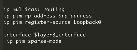
Sample template configuration on non-RP devices such as fabric edges, intermediate nodes and non-RP fabric borders:
● rp-address: The loopback60000 IP address in redundant border devices
● layer3_interface: The whole underlay L3 interface
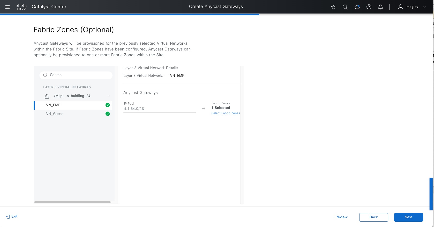
Step 4. Add to Fabric Zone Floor-1 and complete the workflow.
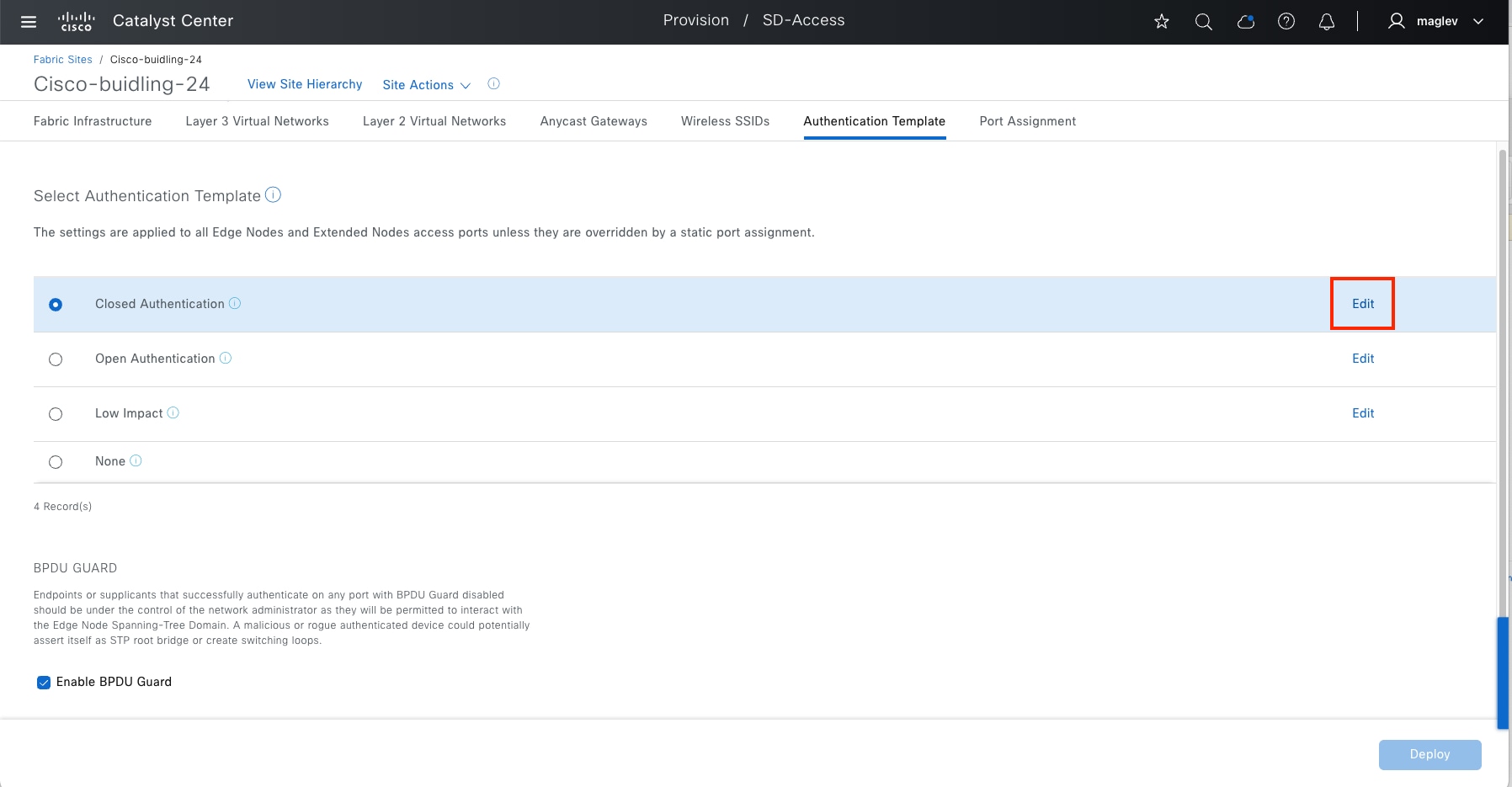
Configure using an authentication template at a site level
Catalyst Center supports predefined authentication templates to simplify the process of implementing authentication on the network. The fabric edges automatically configure after a template is selected.
Predefined Authentication templates:
● Closed authentication: 802.1X + MAB (IBNS 2.0 template). No DHCP/ARP before authentication.
● Open Authentication: 802.1X + MAB. Temporary access is granted prior to Dot1x authentication.
● Low Impact: LDAP + MAB
● None: no authentication, all ports are statically configured.
A site-level authentication template can be changed in day-n operations, authentication parameters can be edited for Closed Authentication, Open Authentication and Low Impact.
In the example, Closed Authentication with the default parameter value is configured for fabric site Cisco‑building-24 and fabric zone Floor-1. The Wake on LAN setting must be enabled to allow the WoL magic packet.
Step 1. From the menu icon button, choose Provision > Fabric sites, click the table view icon, click Cisco-building-24 then click the Authentication Template tab.
Step 2. Choose Closed Authentication then click Edit to change parameters if required.
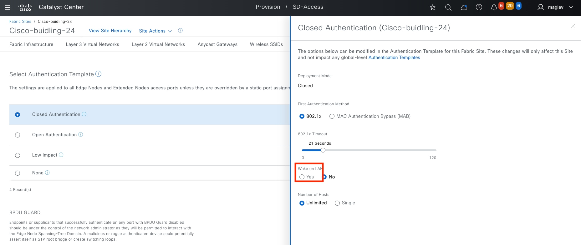
Step 3. The BPDU Guard function is enabled by default, uncheck the check box if it is not required.
Step 4. Enable Wake on LAN if sleeping hosts are connected so WoL magic packets can be sent to a sleeping host. By default, this option is disabled.
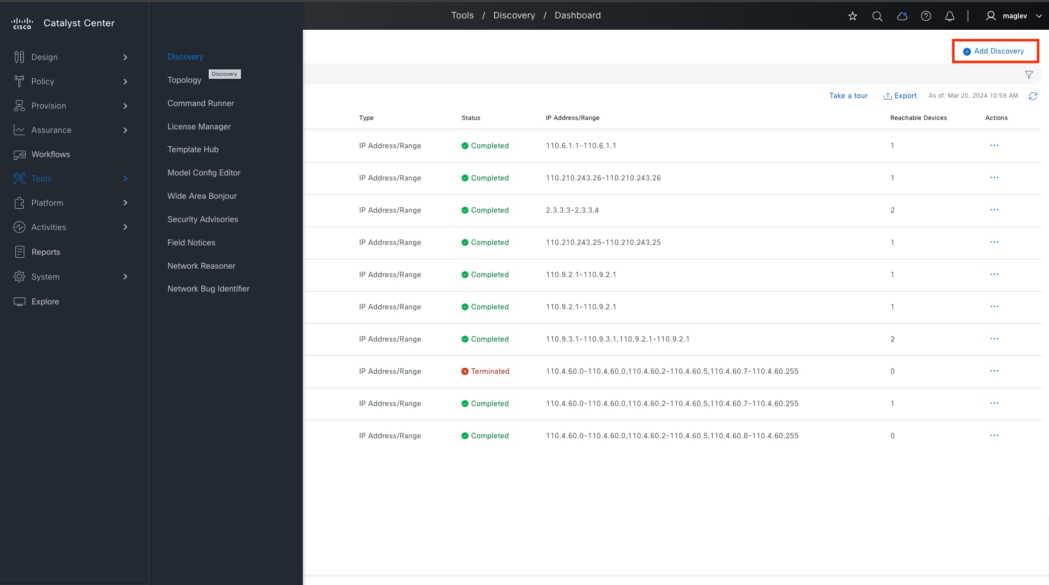
This section focuses on the complete deployment workflow and guidelines, from device discovery through to fabric automation.
The network devices are discovered and added to the inventory then the provision application assigns devices to sites and provisions the configurations defined in the Design window.
The Cisco SD-Access application is used to add devices to a fabric site and configure the Cisco SD‑Access overlay.
Optional but recommended, use LAN automation to configure the underlay.
The processes for deploying the Cisco SD-Access network are as follows:
● Discover and provision two Catalyst 9300 devices to the Cisco-building-24 site
● Configure Catalyst 9300 as border and control plane nodes
● LAN automation to onboard two layers of access nodes (intermediate node and edge nodes)
● Configure fabric edges
● Enable embedded wireless controller
● Configure layer 3 handoff, layer 2 handoff and SD-Access transit
● Configure multicast
● Advanced fabric features on borders
● VN anchoring
● Critical VLAN
● Catalyst 9800 wireless controllers
Loopback0 interfaces are mandatory in Catalyst Center Cisco SD-Access automation. Devices can be discovered and managed with any type of interface, for example: management interface gi0/0 and so on. But for devices to be provisioned in Cisco SD-Access network, loopback0 is required and configured as RLOC in the LISP protocol by Catalyst Center. The only exception is a standalone wireless controller. A fabric wireless controller does not run LISP.
In this deployment guide, the Loopback0 interface is used for discovery, inventory synchronization, and provision.
Discover and provision devices
This section describes the steps to discover and provision devices for Cisco-building-24. Each of these procedures are discussed in the subsequent sections.
Procedure 1. Discover the Catalyst 9300 devices
To discover devices in the network, Catalyst Center must have IP reachability to these devices and CLI credentials of these devices. SNMP and Netconf Yang credentials can be defined in Catalyst Center and pushed during discovery with site assignment. When discovered, the devices are added to inventory, allowing the controller to make configuration changes through provisioning.
Two Catalyst 9300 switches are discovered and will serve as fabric borders.
| Device |
IP |
| Common-A |
Loopback0: 110.4.0.62 |
| Common-B |
Loopback0: 110.4.0.63 |
Step 1. From the menu icon button, choose Tools > Discovery then click Add Discovery in the top right.
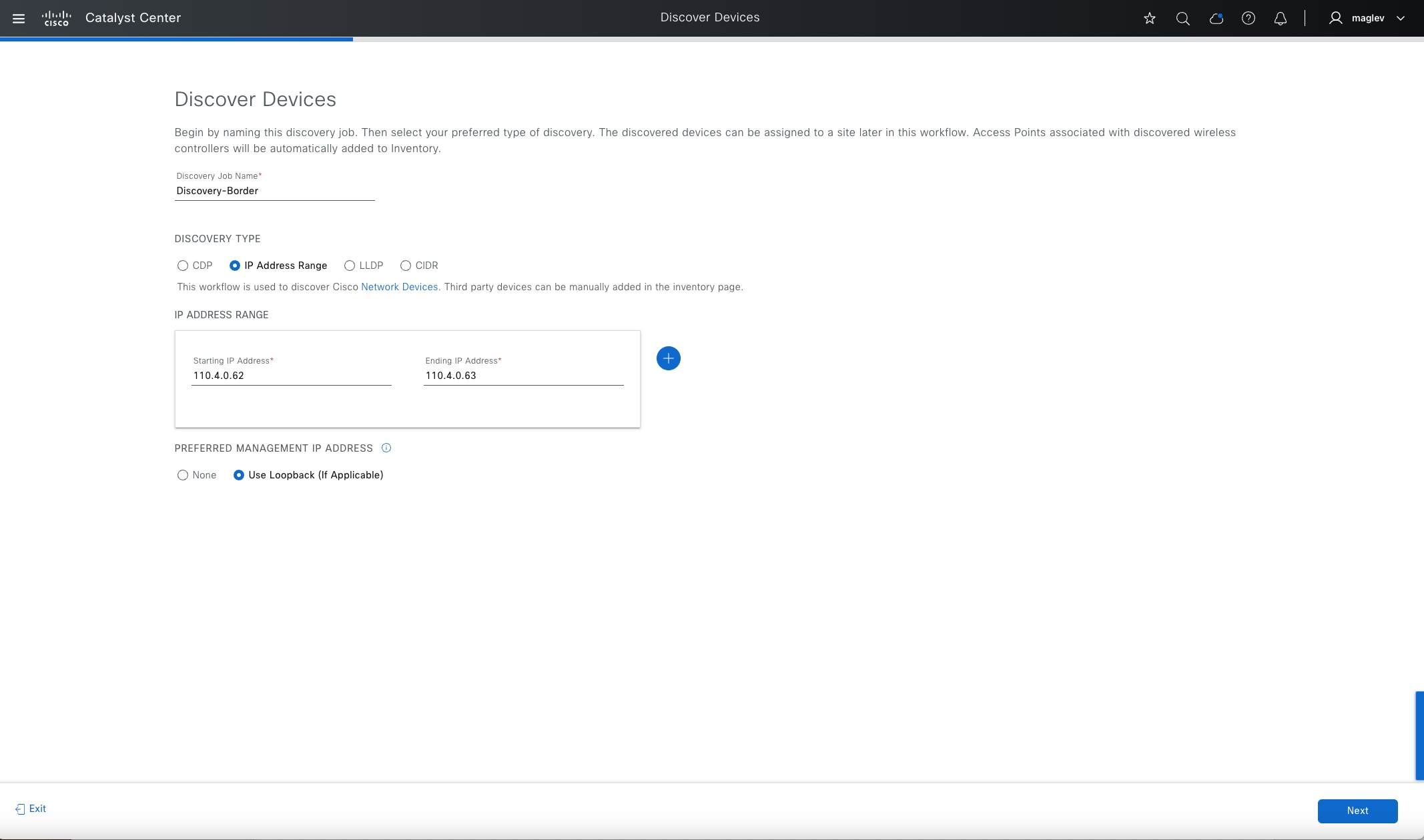
Step 2. Follow the workflow. Enter the required information then click Next.
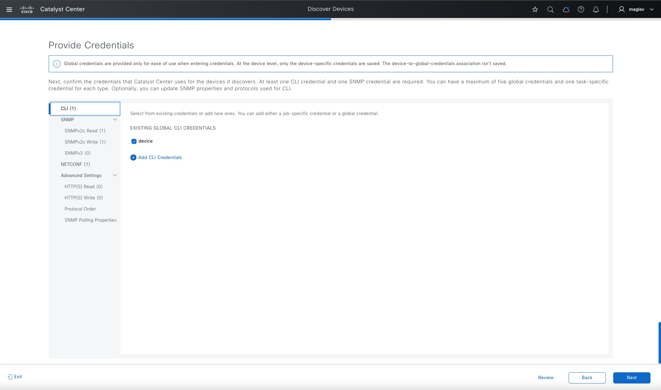
Step 3. Provide the credentials and click Next.
CLI and SNMP credentials are mandatory. Netconf is mandatory for IOS-XE based wireless controllers, such as the Catalyst 9800 series, and optional but recommended for IOS XE based wired devices for Assurance use.
CLI credential needs to match the configuration in devices.
SNMP and Netconf credentials push during discovery with site assignment if devices do not have them configured.
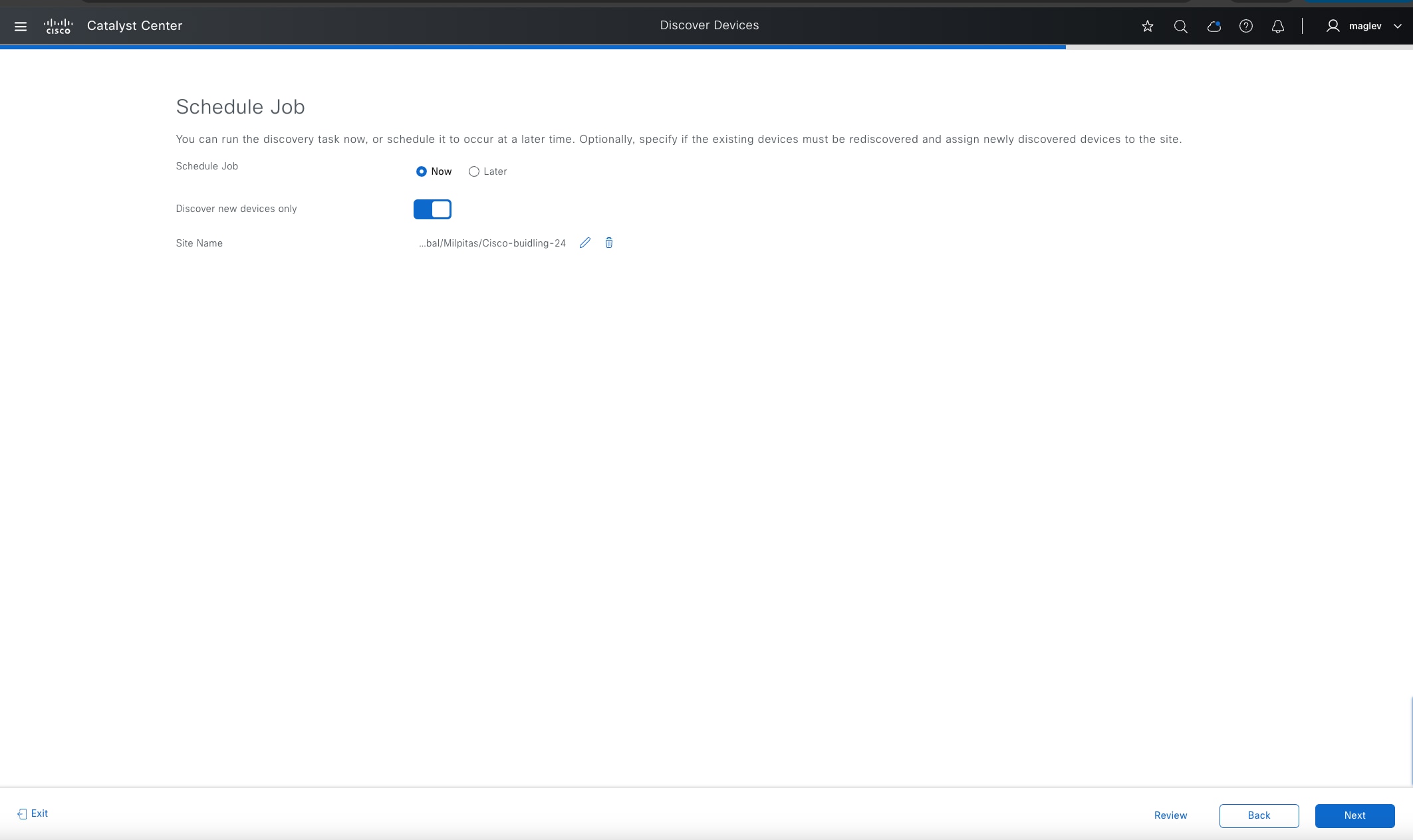
Step 4. Discover with site assignment. Set the Site Name to Cisco-building-24 then click Next to start the discovery.
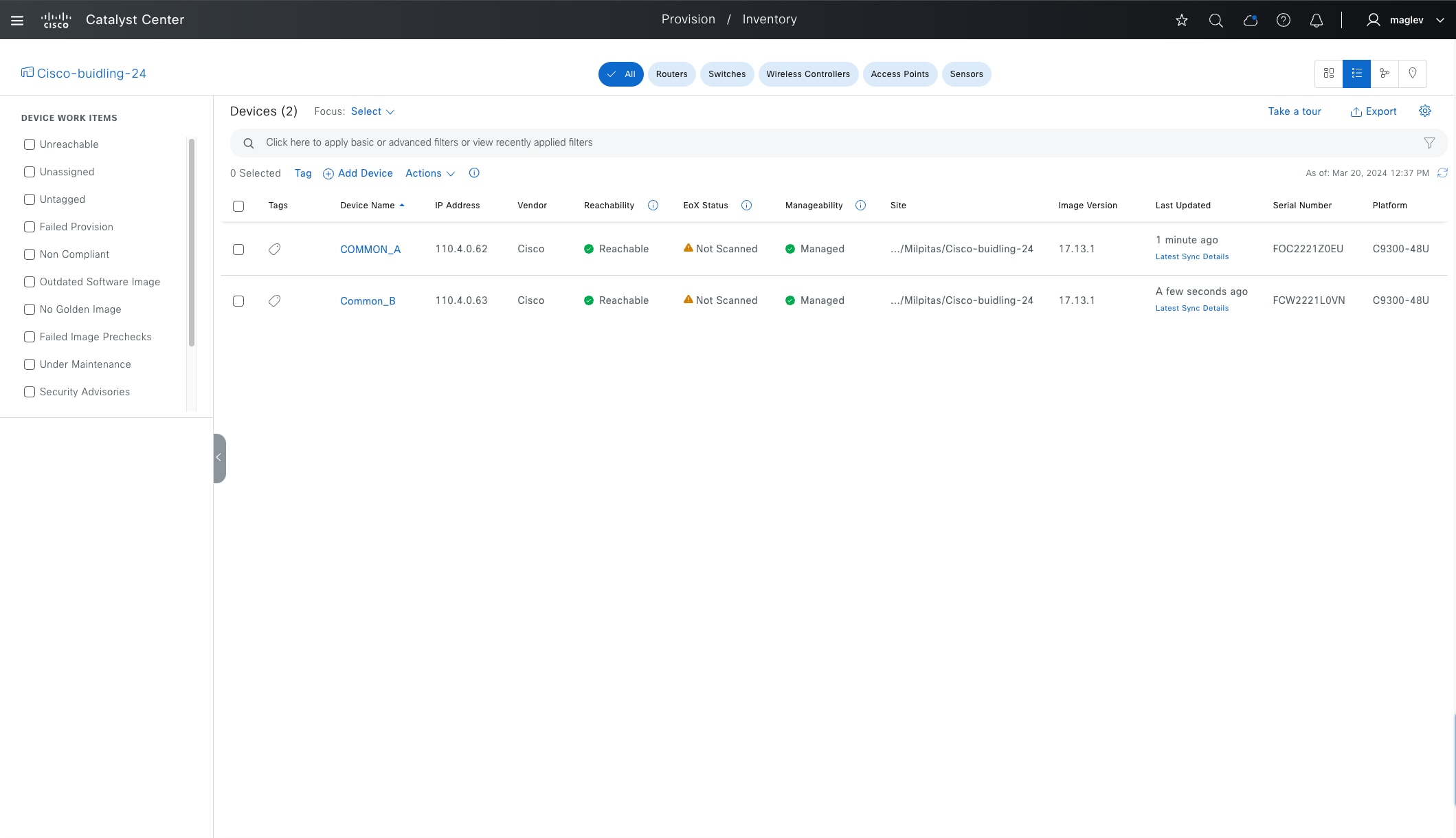
Step 5. Verify in the Inventory window that both devices are added and have the Manageability status Managed after the discovery is done.
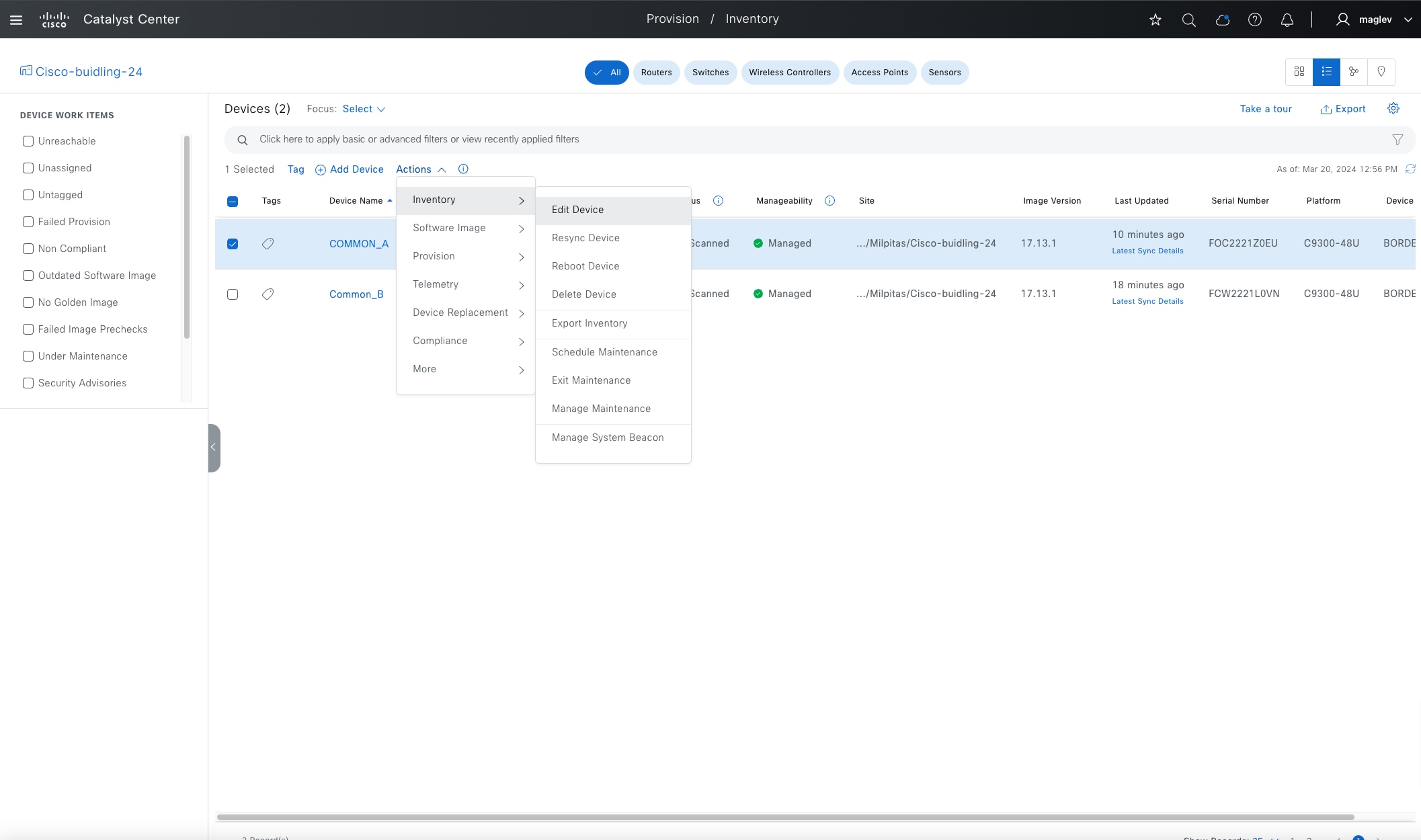
Step 6. View and change the device roles.
The device role is used to position devices in the Catalyst Center topology maps in the fabric site and in the topology tool. The device positions in these applications and tools are shown using the classic three-tiered Core, Distribution, and Access layout.
Device controllability configuration (defined in Network Setting > Telemetry > Wired Endpoint Data Collection) are also pushed to devices that have access roles. Catalyst 9300 switches have default ‘Access’ device roles. During discovery with site assignment, they get the device controllability configuration. After changing to a border router, these configurations are removed.
Step 7. Choose the device in the Inventory window then click Actions > Inventory > Edit Device.
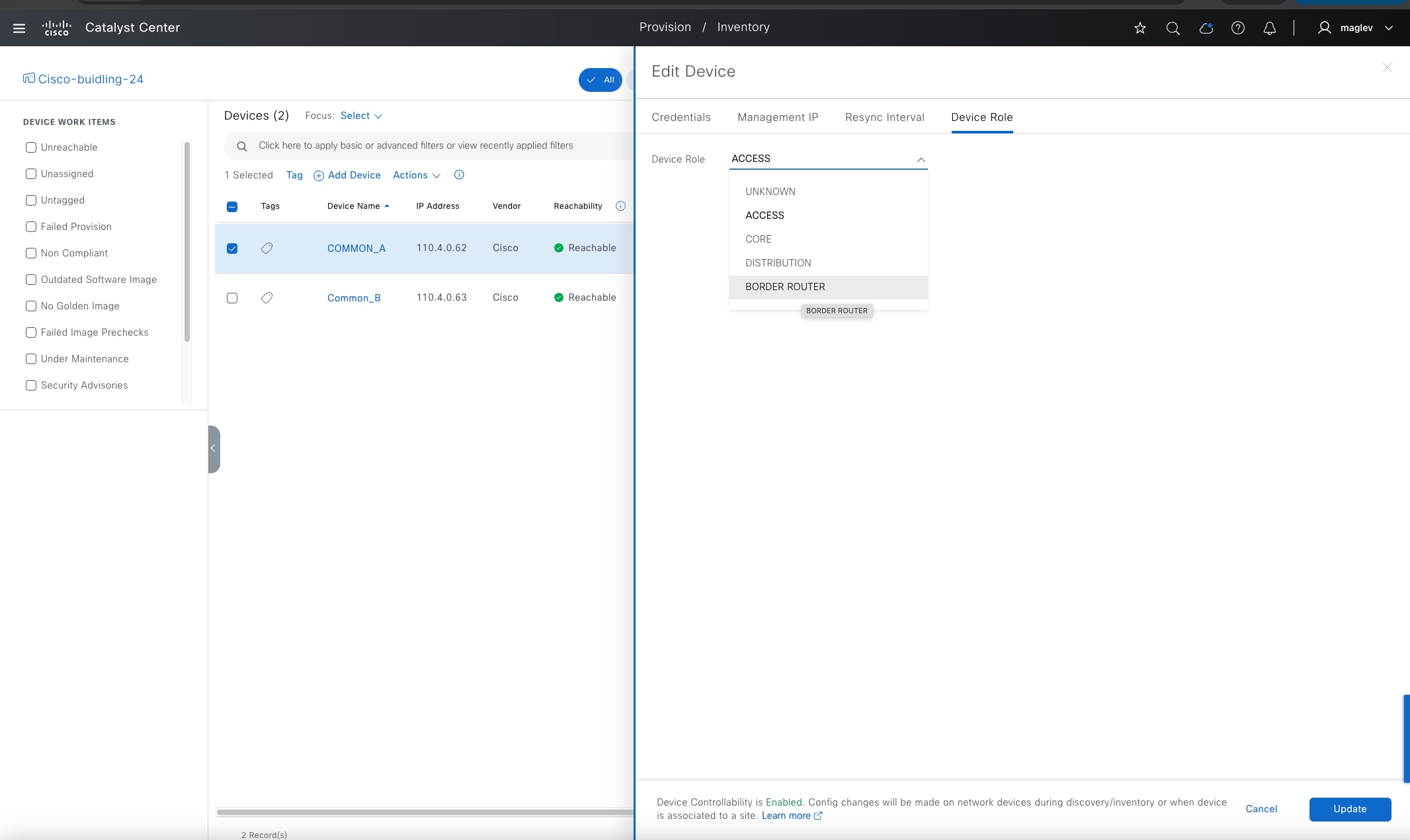
Step 8. From the Device Role tab, change the role to Border Router for both devices.
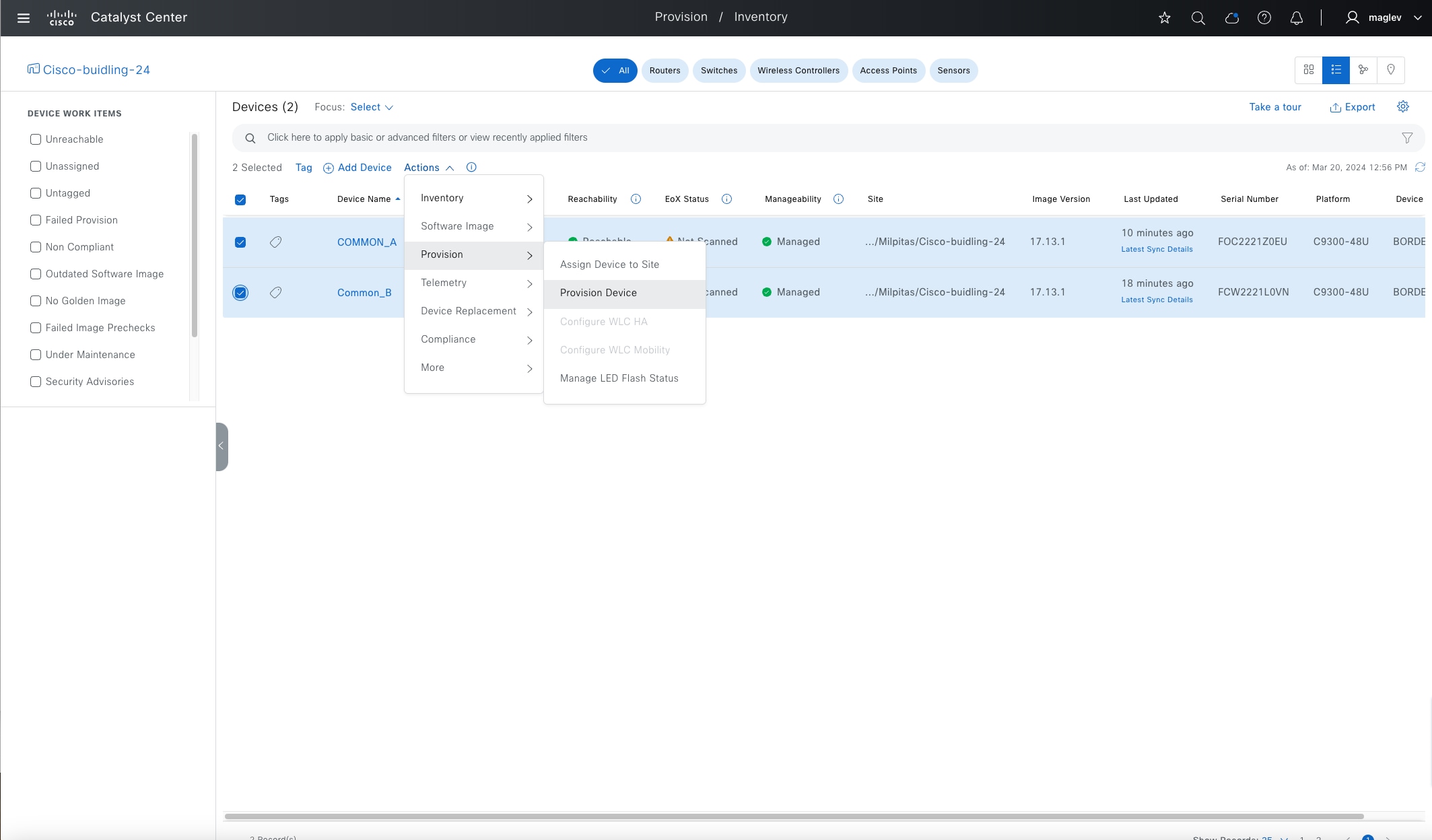
Procedure 2. Provision the Catalyst 9300 devices to the site
Provisioning devices to sites pushes the configurations defined in the Network Design window: AAA, DNS, NTP, Telemetry, and so on. Devices can be assigned with fabric roles only after provisioning.
Step 1. Check the check boxes for both devices then choose Actions > Provision > Provision Device and complete the workflow.
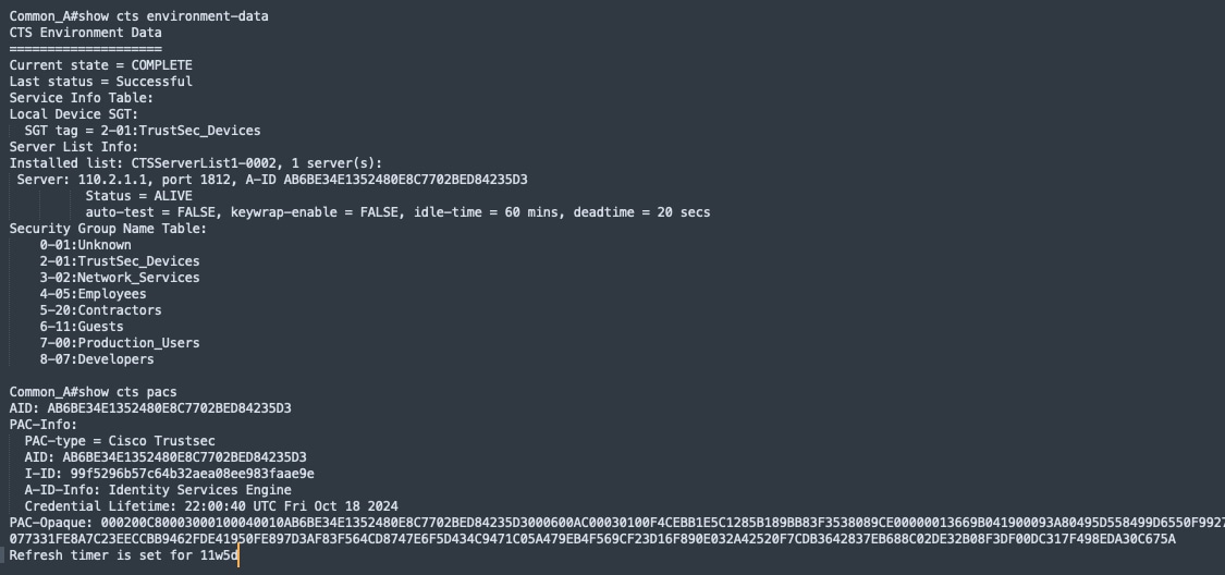
After provisioning, the device is added to Cisco ISE and downloads Cisco TrustSec information from Cisco ISE.
Step 2. Use the commands show cts environment-data and show cts pacs to view from the device.
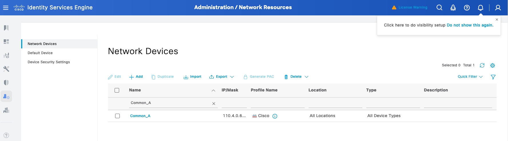
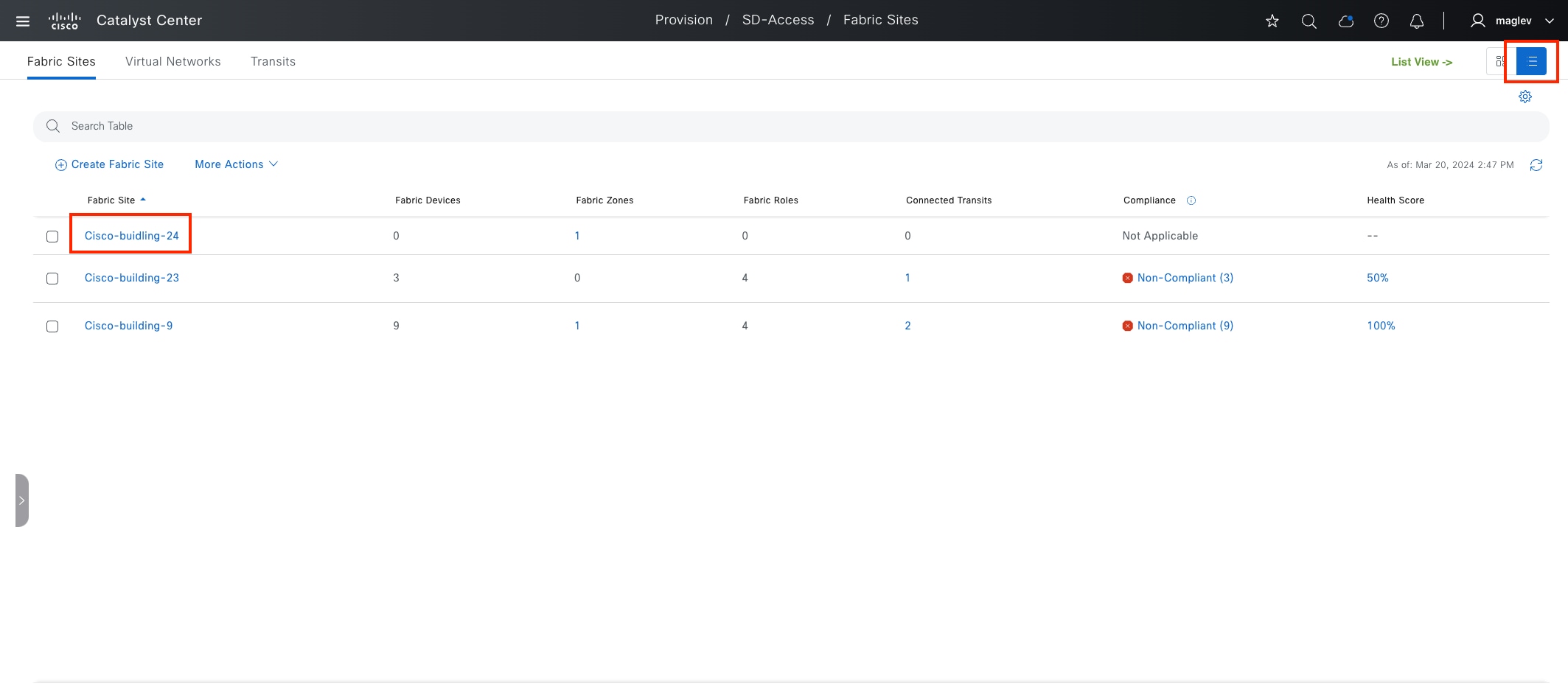
Procedure 3. Configure Catalyst 9300 as border and control plane nodes
A fabric network must have at least an edge node and control plane node to function. This allows endpoints to traverse their packets across the overlay to communicate with each other (policy dependent). The border node allows communication from endpoints inside the fabric to destinations outside of the fabric along with the reverse flow from outside to inside.
The first device added to a fabric site must have control plane role, it can be a standalone control plane node, a colocated border and control plane node or a FiaB. When a control plane device is added, Catalyst Center provides the options to configure the fabric site as LISP/BGP or LISP Pub/Sub (recommended). Up to six control plane nodes are supported in a fabric site.
When provisioning a border node, there are number of different automation options in the GUI:
● Can have a layer-3 handoff, a layer-2 handoff, or both (platform dependent)
● Can be connected to an IP transit, to an SD-Access transit, or both (platform dependent).
● Can provide connectivity to the internet (external border), connectivity outside of the fabric site to other non-internet locations (internal border), or both (anywhere border).
External border
Connected to unknown routes such as the internet, WAN, or MAN. It is the gateway of last resort for the local site’s fabric overlay. External Border exports all the fabric subnets to outside the fabric site as eBGP summary route. A Border connected to a Cisco SD-Access transit must always use the External border functionality.
Internal border
Connected to the known routes in the deployment, such as a data center (shared services such as DHCP with DNS and so on). This border exports all the fabric subnets to outside the fabric site as an eBGP summary route and imports and registers these eBGP-learned routes from outside the fabric site into the site-local control plane node.
Anywhere border
Functions as both internal and external border and is used when the network uses one set of devices to egress the site. It is directly connected to both known and unknown routes.
In this section, the two Catalyst 9300 switches are added to the fabric site Cisco-building-24 and have colocated border and control plane roles. LISP Pub/Sub is configured. IP transit and Cisco SD-Access transit are demonstrated Configure Transits.
Note: Adding a device to a fabric site requires a Loopback0 interface. Configure a loopback0 address before or use LAN automation to configure.
Step 1. From the menu icon button, choose Provision > Fabric Sites, click the table view icon, then click Cisco-building-24.
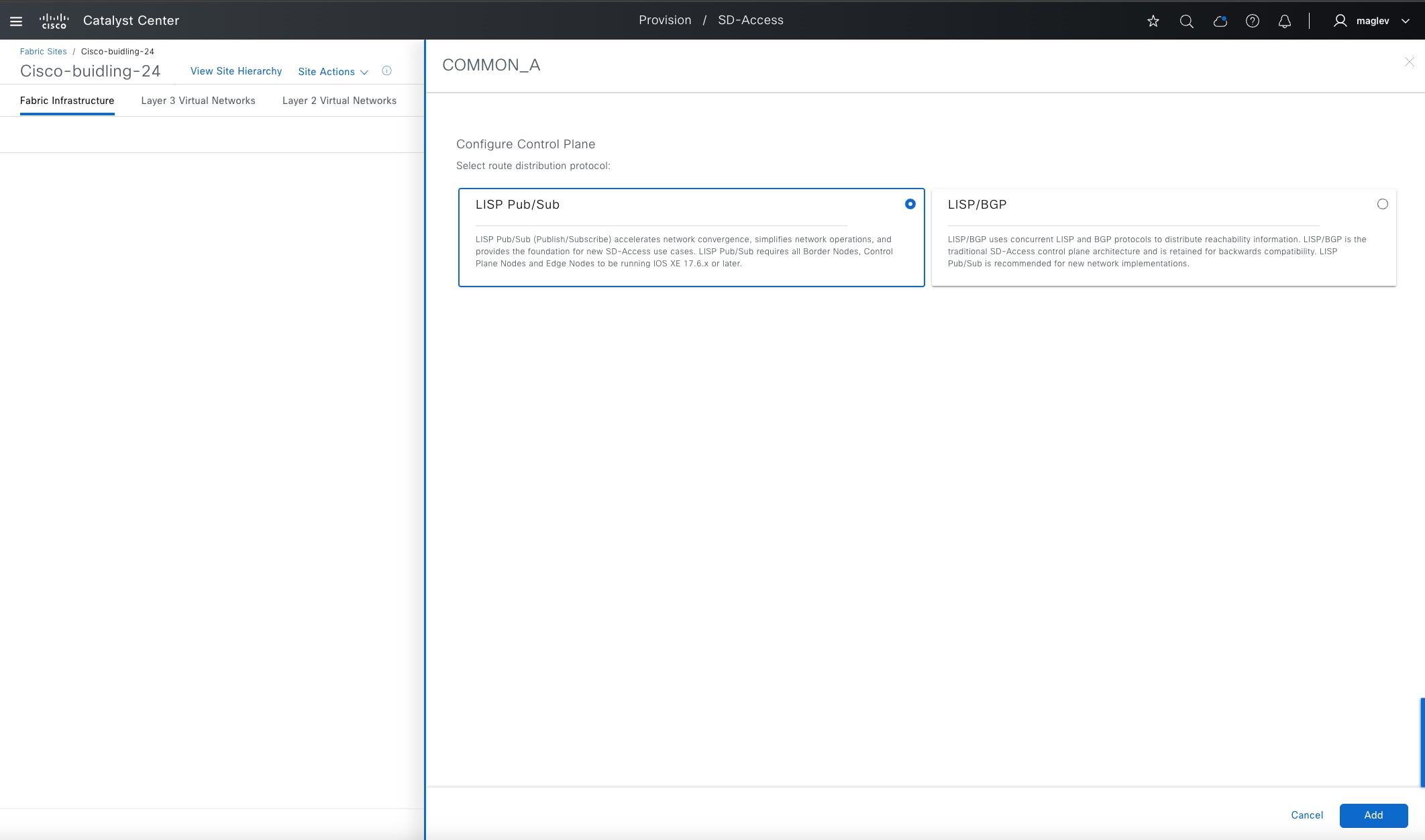
Step 2. Click one of the devices. (Devices without a fabric role are grayed out.)
Step 3. In the sidebar on the right, enable Control Plane Node and Border Node.
● For the Control Plane Node, click LISP Pub/Sub > Add.
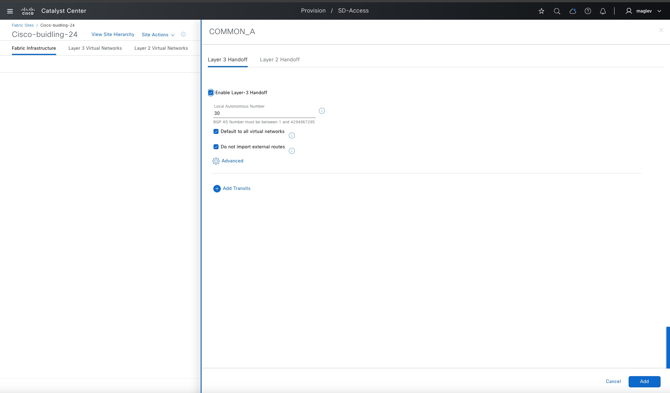
● For the Border Node, check the Enable Layer-3 Handoff check box.
Local AS number is the BGP AS number on the border devices. It can be pre-configured, if not, Catalyst Center provisions the configuration to the device.
Table 23. Internal border, external border and anywhere border options
|
|
Default to all Virtual networks |
Do not import external routes |
| Internal Border |
– |
n/a |
| External Border |
✔ |
✔ |
| Anywhere Border |
✔ |
– |
Step 4. Configure the Catalyst 9300 as external borders. Check the Default to all Virtual networks and Do not import external routes check boxes then click Add.
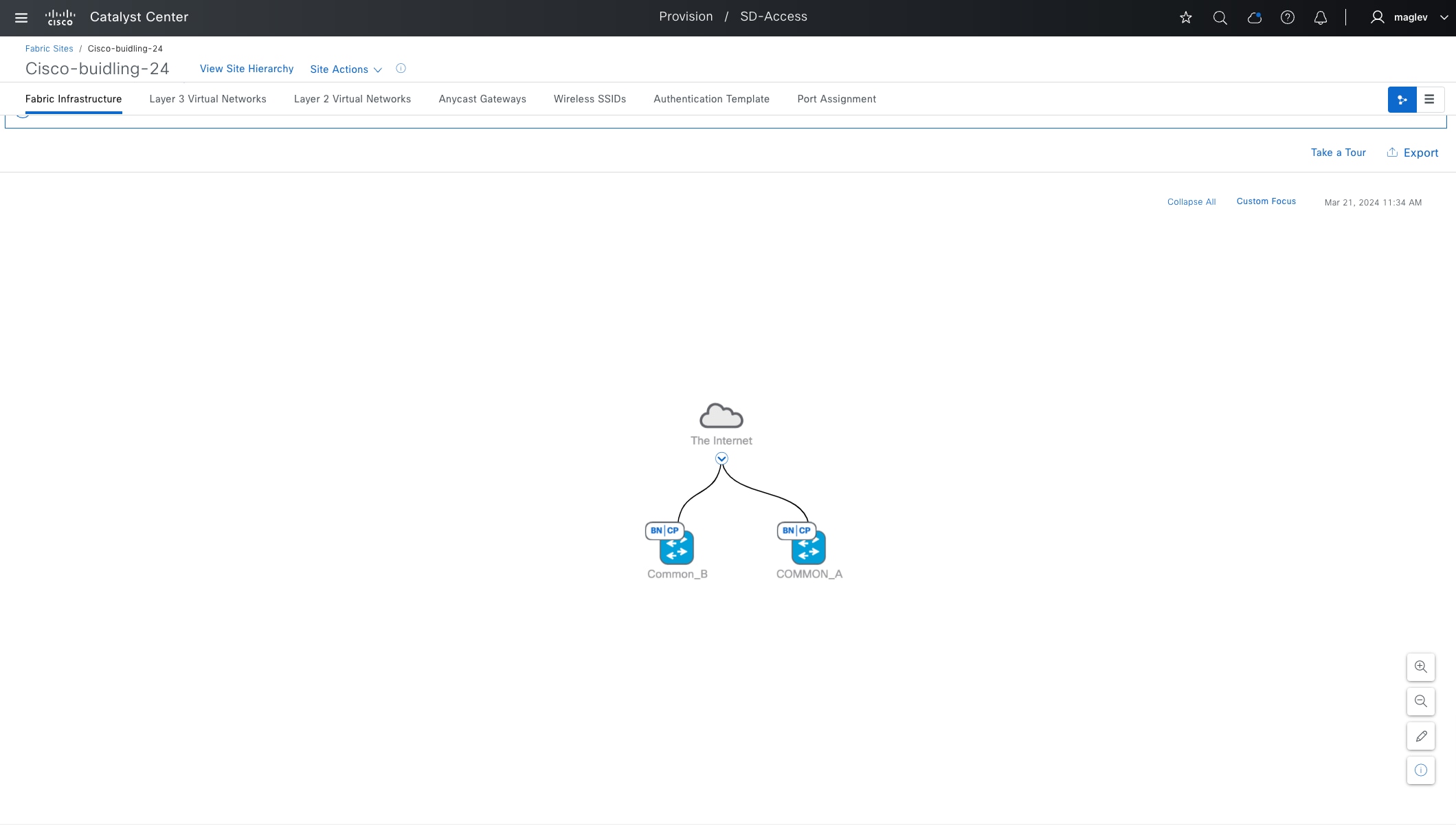
Step 5. Complete the workflow to provision configurations to Common-A and repeat the same procedure on Common-B.
Note: Since Common-A is already configured as a control plane node with LISP Pub/Sub, when configuring Common-B as a second control plane node, the option to select LISP BGP and LISP Pub/Sub is disabled.
After provisioning, both devices in the topology view appear blue with the fabric role tagged as BN|CP.
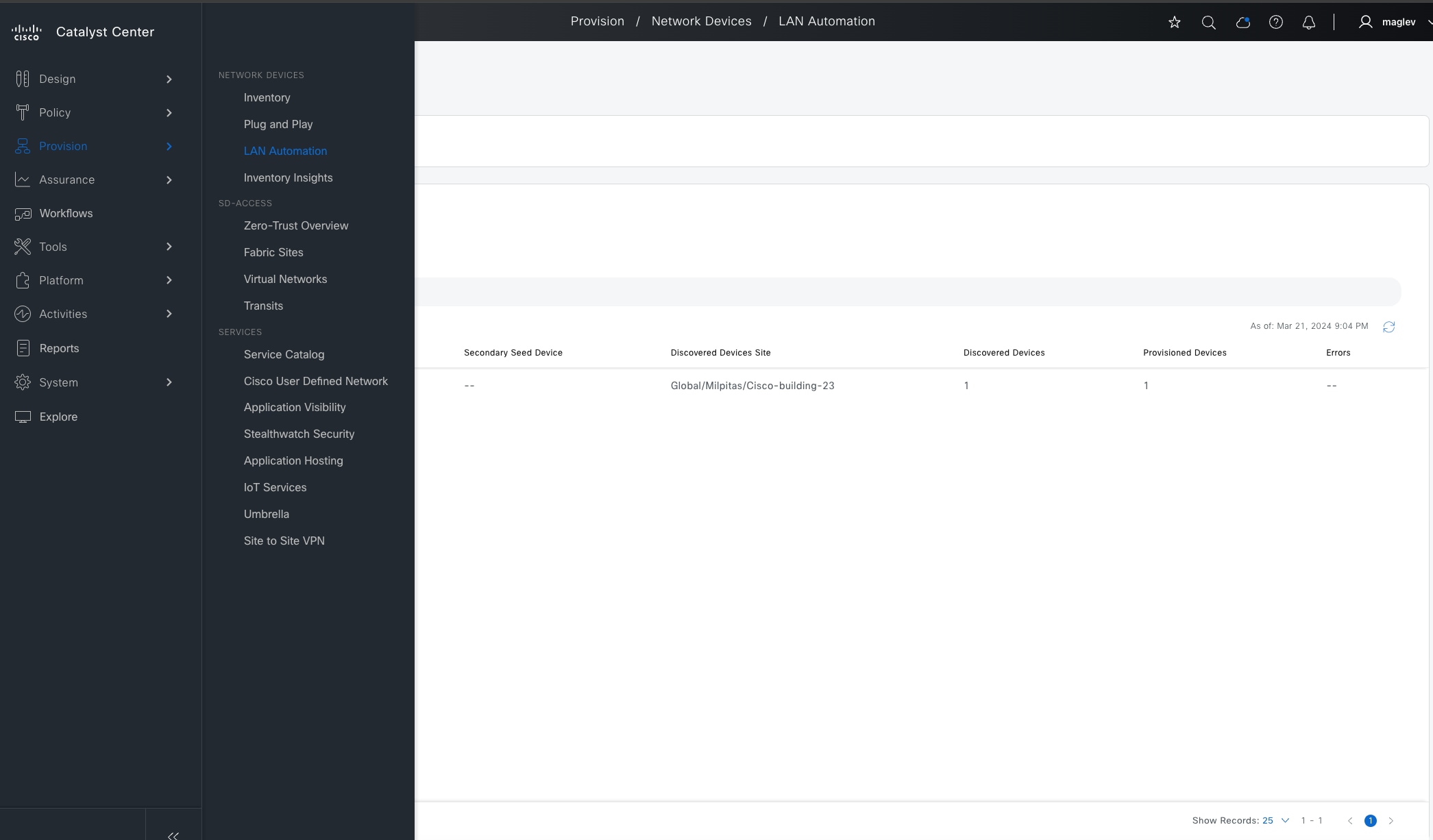
Onboard underlay device with LAN automation
LAN automation uses up to two seed devices and starting from the seed devices can “walk out” up to five layers within the network hierarchy and automate the deployment of new devices it discovers through PnP process. LAN automation is started only on directly connected neighbors and is intended to support the deployment of an underlay suitable later for the overlay of a Cisco SD-Access fabric.
To start LAN automation, seed devices and LAN pool are required. Catalyst Center should have reachability to the LAN pool subnet.
LAN automation currently only supports ISIS protocols and router platforms are not supported as seed devices. For detailed information on LAN automation, see the Cisco Catalyst Center Cisco SD-Access LAN Automation Deployment Guide.
In this section, Common-A and Common-B are used as seed devices, two tiers of devices are onboarded. Tier-1 is used as intermediate switch. Tier-2 is used as fabric edges.
Procedure 1. LAN automation to discover devices
Step 1. To start LAN automation, from the top-left corner, click the menu icon, choose Provision > LAN Automation.
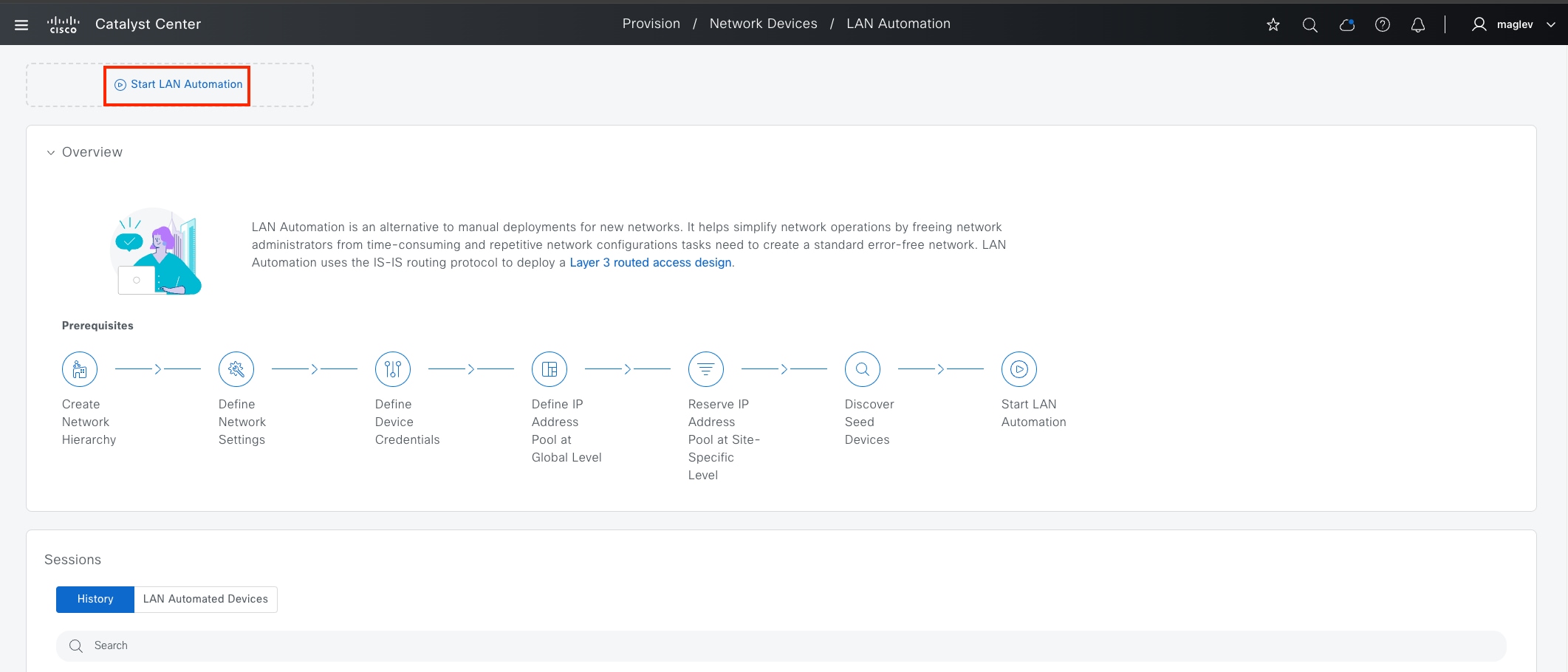
Step 2. Click Start LAN Automation.
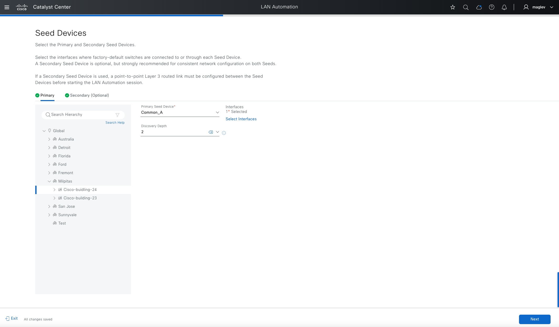
Step 3. Choose Cisco-building-24 from the Hierarchy pane. Provide the required field information then in the Seed Devices window click Next:
| Field |
Value |
| Primary
|
Common-A |
| Interfaces |
GigabitEthernet1/0/10 |
| Discovery Depth |
2 |
| Secondary |
Common-B |
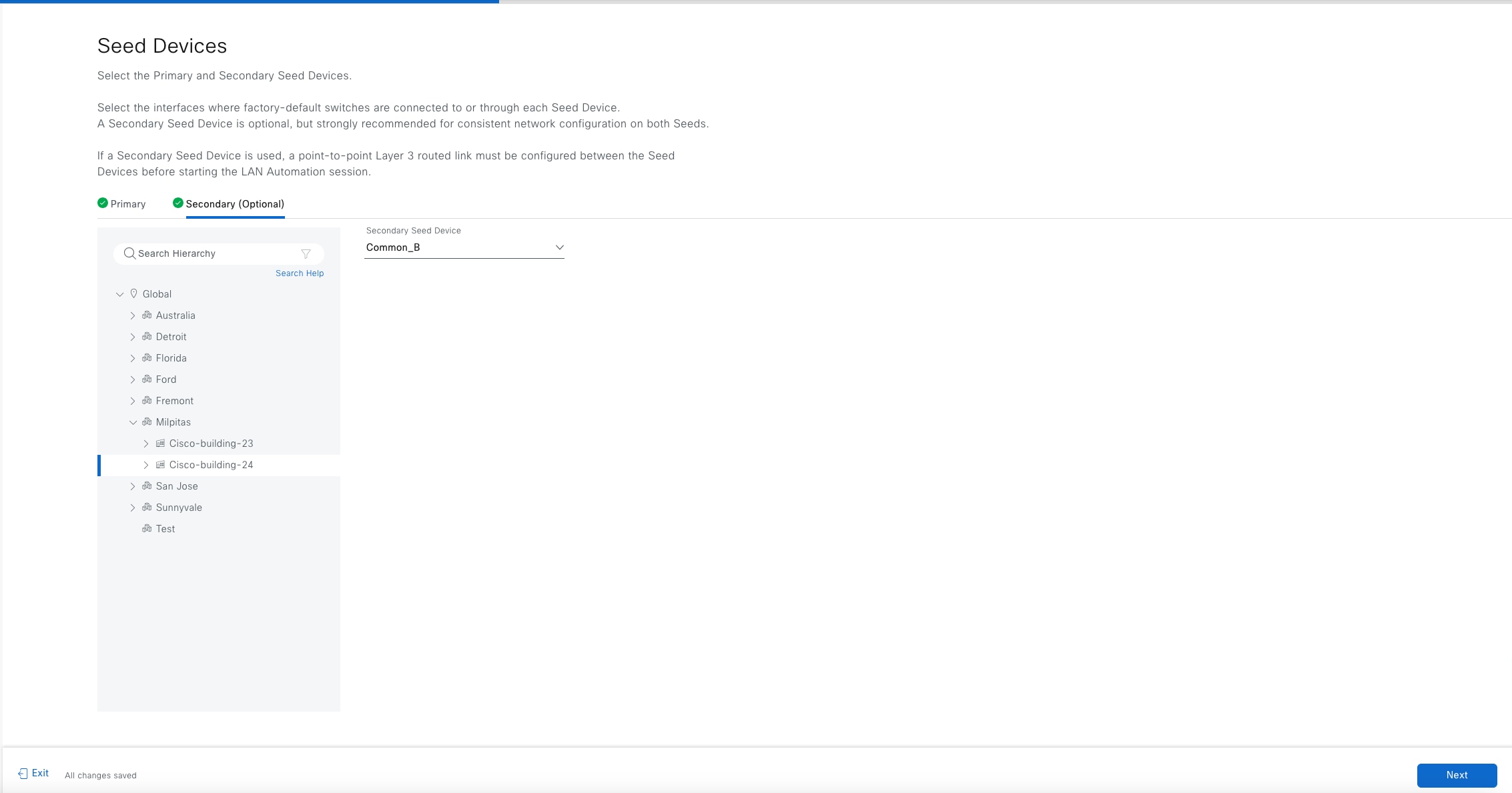
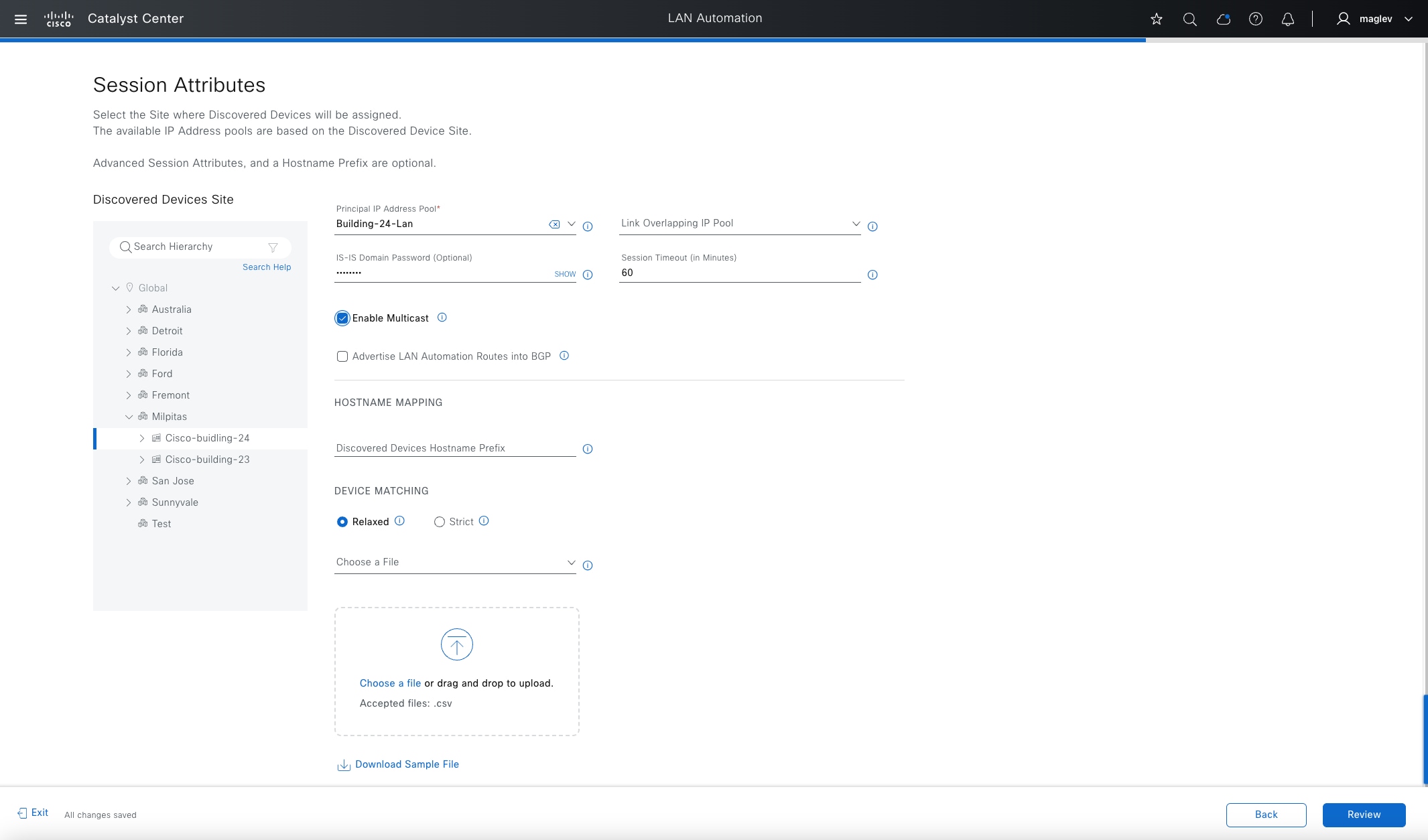
Step 4. Session attributes define advanced configurations and session control.
Table 24. Session attributes used in this deployment
| Field |
Value |
Use |
| Principal IP Address Pool |
Building-24-Lan |
Layer 3 link, Loopback IP, native multicast underlay |
| IS-IS Domain Password (optional) |
Cisco123 |
IS-IS |
| Session Timeout |
60 minutes |
Auto Stop LAN Automation after 60 minutes, if not provided, manual stop is required. Only recommended in a stable network or use a longer timeout (max 1 week) |
| Enable Multicast |
✔ |
Configure seed devices as Native Multicast RP and discovered devices as subscribers to multicast traffic |
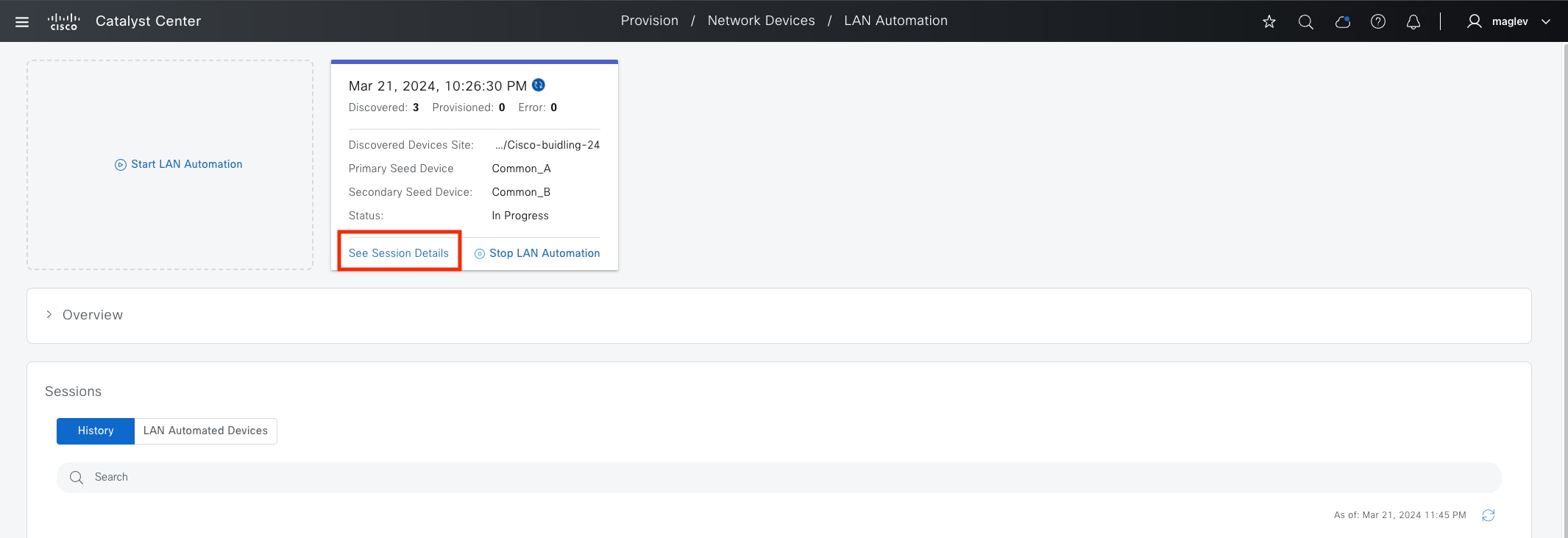
Step 5. In the Review window, verify the information accuracy then click Start.
Step 6. In the LAN Automation dashboard, monitor the Session status, or click See Session Details.
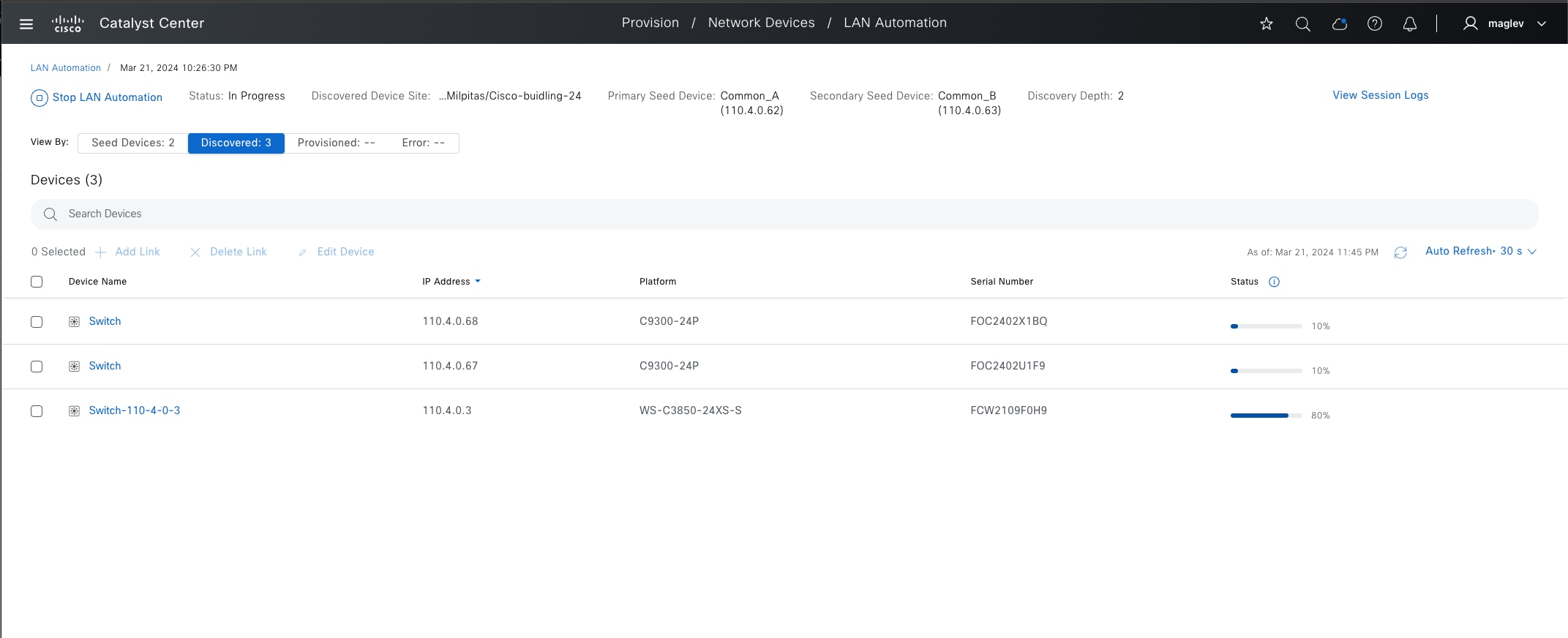
Step 7. Choose Discovered to see the progress of each device.
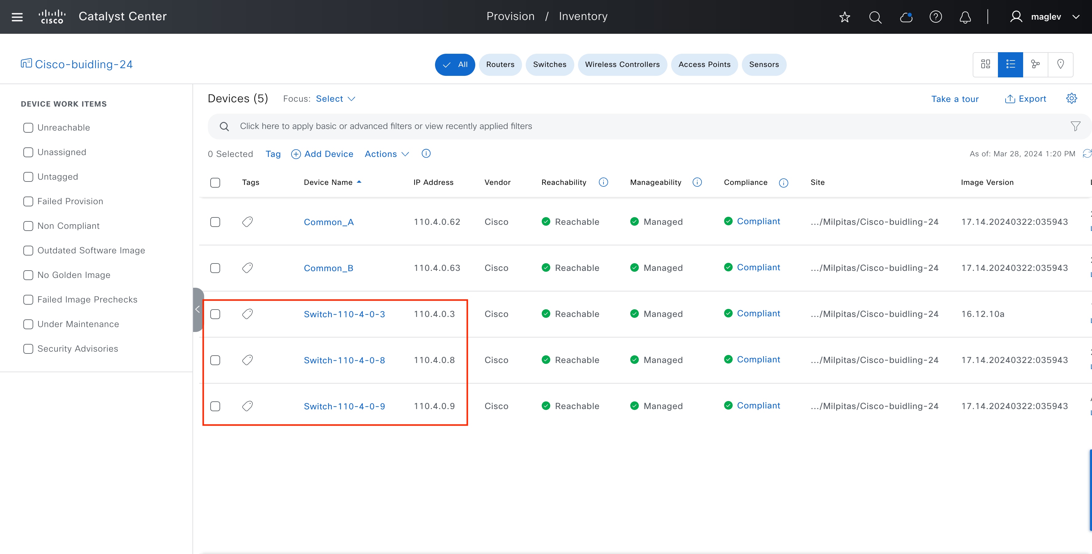
Note: The Catalyst 3850 switch in this deployment is a Tier-1 switch (is used as an Intermediate Node), Tier-2 switches (the 2x Catalyst 9300) are processed in LAN automation after the Tier-1 switch is in managed status in Inventory.
After all the devices are discovered and managed in Inventory, LAN automation can be stopped to convert the link to a layer 3 link. Alternatively, when the Session Timeout expires, if there are no devices in the onboarding process, LAN automation stops automatically.
Tech tip: If the Golden image is marked in Image Repository, during the PnP process, the discovered devices upgrade to the Golden image.
All the three devices are onboarded into Catalyst Center.
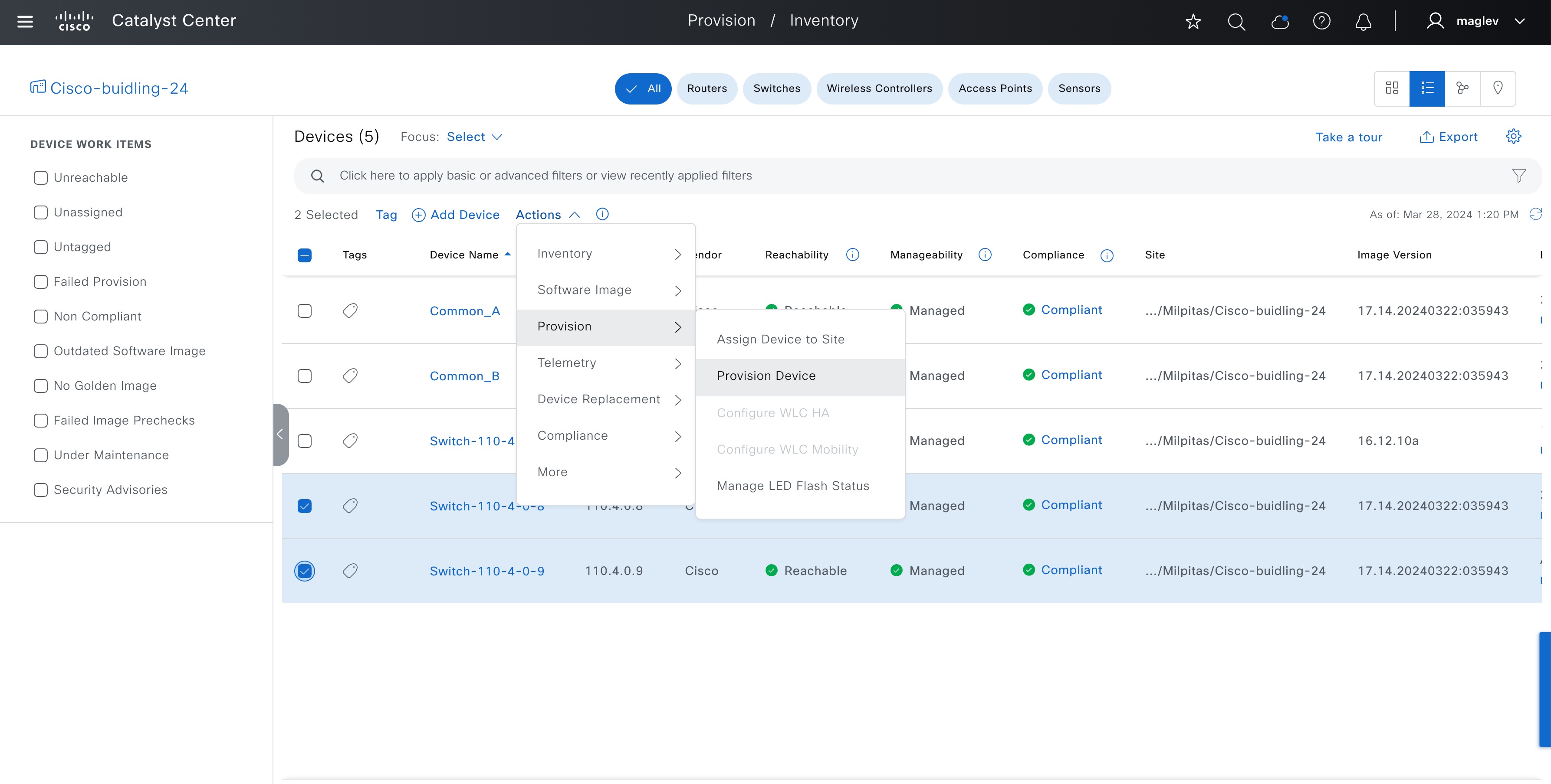
Procedure 2. Provision discovered devices to fabric as fabric edges
Devices onboarded through LAN automation need to be provisioned from the Provision/Inventory window before they can be added to the fabric with a fabric role assignment.
Step 1. From the top-left corner, click the menu icon and choose Provision > Inventory then choose Actions > Provision > Provision Device.
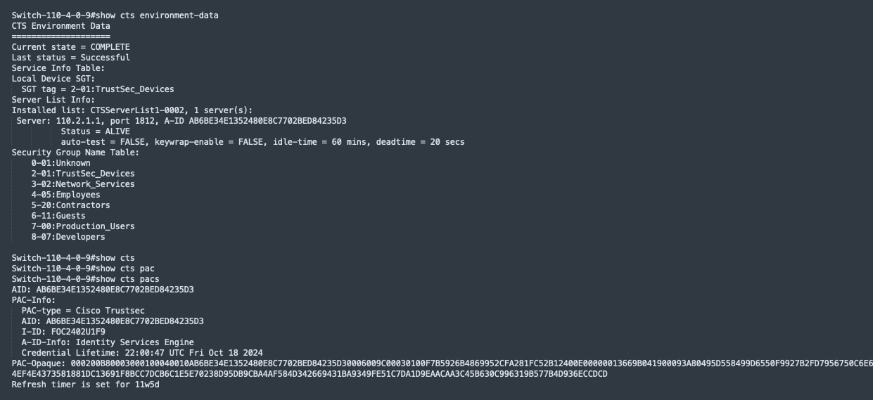
Same as border devices, LAN automated devices are added to Cisco ISE and have Cisco TrustSec information downloaded.
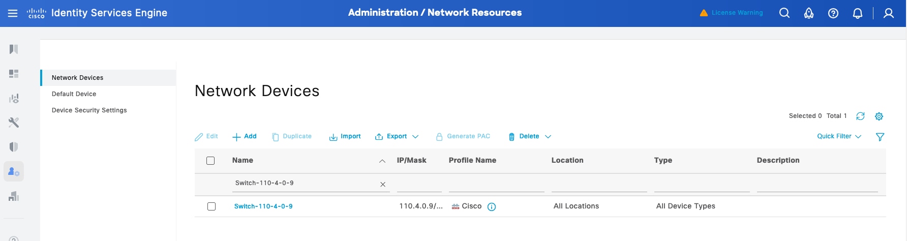
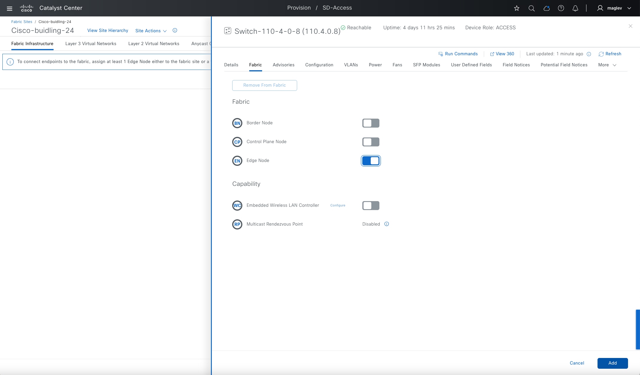
Step 2. From the top-left corner, click the menu icon and choose Provision > Fabric Sites, click the table view icon in the top right, choose Cisco-building-24, right-click on the device, enable Edge Node, then click Add.
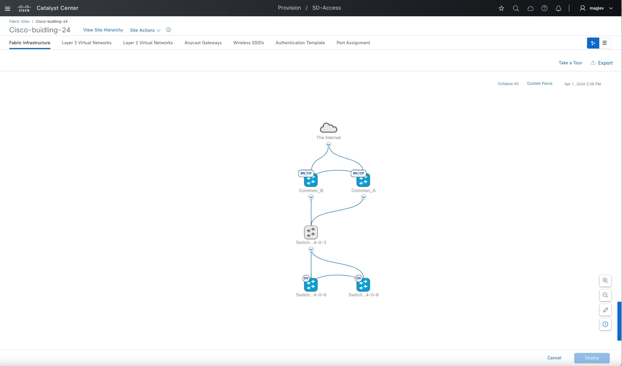
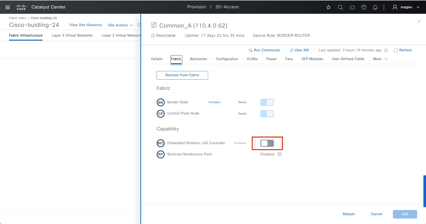
Step 3. Click Deploy.
Configure Cisco SD-Access wireless with an embedded wireless controller
An embedded wireless controller can be enabled on Catalyst 9000 devices with border and control place roles, edge role, or FiaB. A wireless subpackage and Netconf-yang are required.
Catalyst Center provides the option to import, install and activate a wireless subpackage when configuring an embedded wireless controller.
The embedded wireless controller enables devices in Common-A and Common-B and configures as an N+1 Peer.
| Device |
Primary Managed Location |
Secondary Managed Location |
| Common A |
Cisco-building-24/Floor-1 |
Cisco-building-24/Floor-2 |
| Common B |
Cisco-building-24/Floor-2 |
Cisco-building-24/Floor-1 |
Procedure 1. Enable EWC on a Catalyst 9000
Step 1. From the top-left corner, click the menu icon and choose Provision > Fabric Sites, click the table view icon in the top right, choose Cisco-building-24, right click the device Common-A, and enable Embedded Wireless Controller.
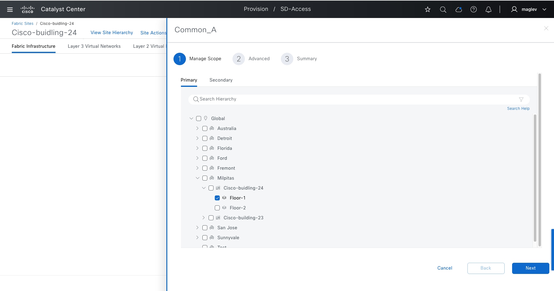
Step 2. Click Primary > Floor-1 then click Secondary > Floor-2.
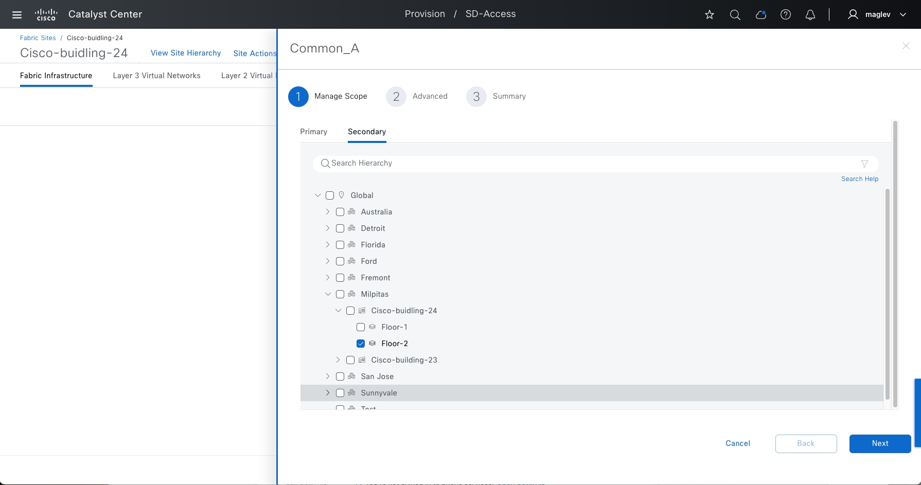
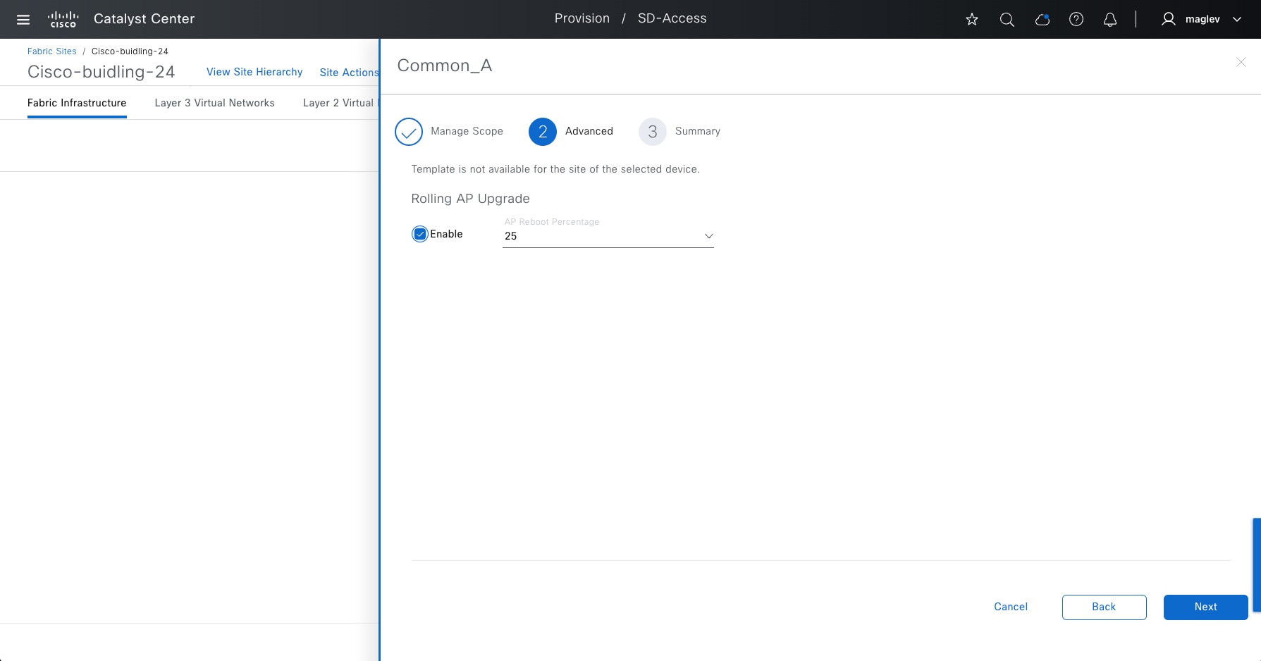
Step 3. Enable Rolling AP Upgrade (optional but recommended).
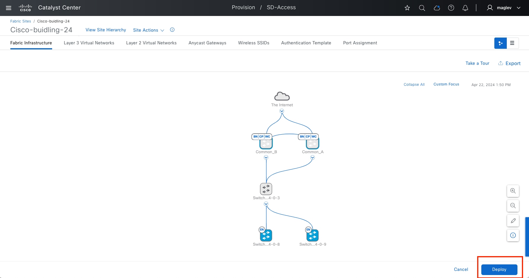
Step 4. Complete the workflow and repeat the same on Common-B, Primary > Floor-2, Secondary > Floor-1.
Step 5. Click Deploy to push the configuration.
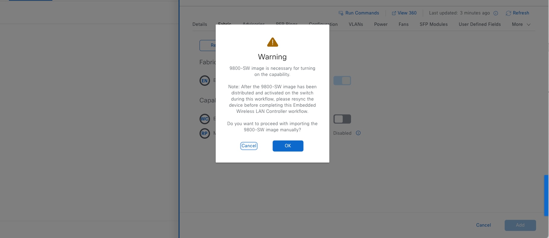
Tech tip: If the wireless subpackage is not installed, Catalyst Center provides a workflow to install and activate the wireless subpackage. See the example image.
Step 6. Click OK to continue.
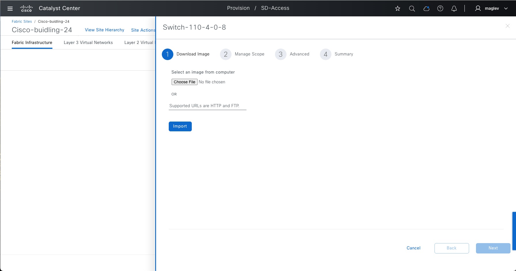
Step 7. Import the wireless package from your computer or from the HTTP/FTP server.
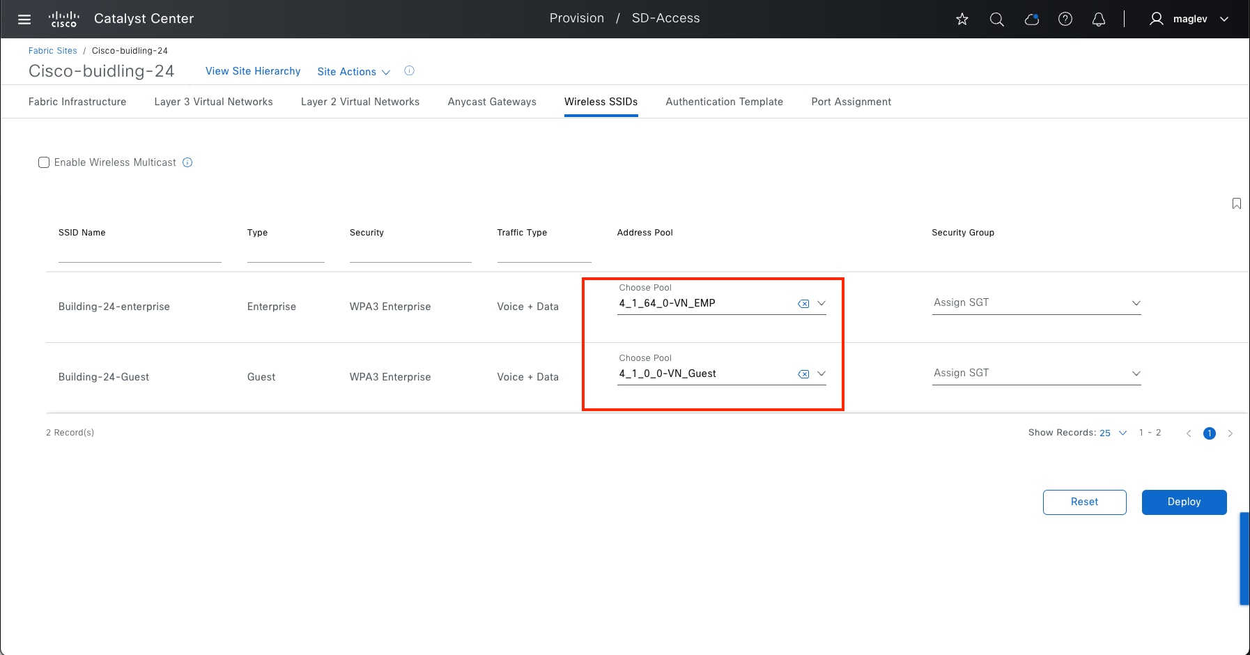
After importing the image, in the same workflow, Catalyst Center installs and activates the wireless subpackage then allows you to configure the Primary and Secondary managed locations and provision configurations to devices.
Procedure 2. Associating IP address pool to SSID
Each SSID for a fabric site must be assigned an IP address pool so that wireless hosts are associated with the correct subnet when connecting to the wireless network.
Step 1. From the top-left corner, click the menu icon and choose Provision > Fabric Sites, click the table view icon from the top right, choose Cisco-building-24, then click the Wireless SSID tab, associate IP pools with SSID then click Deploy.
Step 2. Complete the workflow. Security Group is optional.
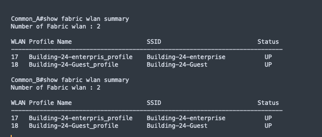
Tech tip:
1. Only IP address pools with Fabric-wireless enabled are available for SSID to IP pool association.
2. One IP address pool can be used to associate to different SSIDs.
3. Cisco ISE can override the IP address pool during client onboarding.
Step 3. Use the command show fabric wlan summary to validate that WLANs are up in Common_A and Common_B.
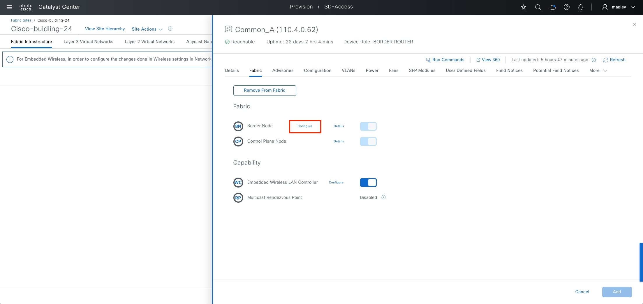
Provide access to shared services and internet services using IP transit
Shared services such as DHCP and DNS in data center or internet service generally reside outside of Cisco SD-Access fabric. IP transit with layer 3 handoff is used to advertise these shared services routes or advertise default route from peer devices so that endpoints in the fabric can access them.
Access to shared services with the default route is a multistep workflow done primarily on the command‑line interface (CLI) of the peer device.
a. Create the VRF-Lite connectivity between peer device and border node.
b. Run two-way route leaking between VRF to GRT and the other way around on a peer device.
c. Establish BGP peering for each VRF with GRT between a peer device and the border node.
Step a and step b need to be manually configured on a peer device. Step c can be done through Catalyst Center using a layer 3 handoff workflow. This example procedure shows adding a layer 3 handoff for VN_EMP and VN_Guest on fabric border devices Common_A and Common_B.
The IP transit C-INTERNET was configured in Procedure 2: Create IP Transit.
Step 1. Navigate to the border configuration to add it as a layer 3 handoff with the information in this table prepared first.
| Information required |
Use |
| Interface between border and remote BGP peer device |
Configure the interface as a trunk port on a switch platform. |
| VLAN for each VNs |
Create VLAN and SVI on a switch platform or a subinterface with VLAN encapsulation on a router platform to communicate with peer devices. |
| IP pool with IP address peer |
Configure an IP address on SVI on a switch platform or on a subinterface on a router platform to communicate with peer devices. |
Note: Catalyst Center offers options to automate IP addresses on borders to communicate between borders and remote BGP peer devices, including:
1. Catalyst Center to assign IP address (/30 subnet) from a predefined IP pool.
2. Customized IP address peer allows the assignment of an IP address to an eBGP peer.
You can use either Catalyst Center to allocate IP address peers or use a customized IP address peer. Combining both is not supported on the same device.
Step 2. In the fabric site Cisco-building-24, click the Fabric Infrastructure tab then click border Common-A.
Step 3. In the slide-in pane, click Border Node > Configure.
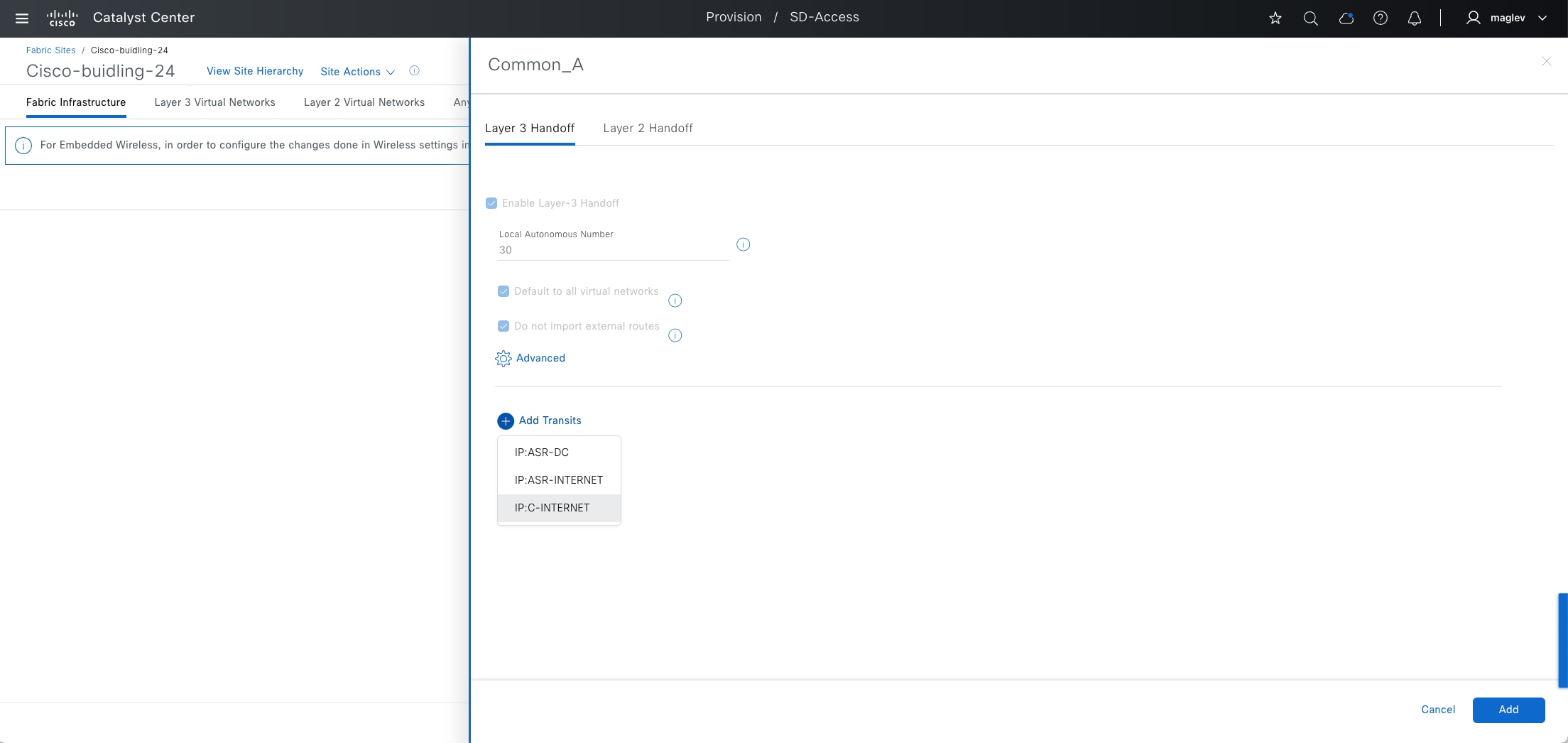
Step 4. Click the Layer 3 Handoff tab then click Add Transits > IP:C-INTERNET.
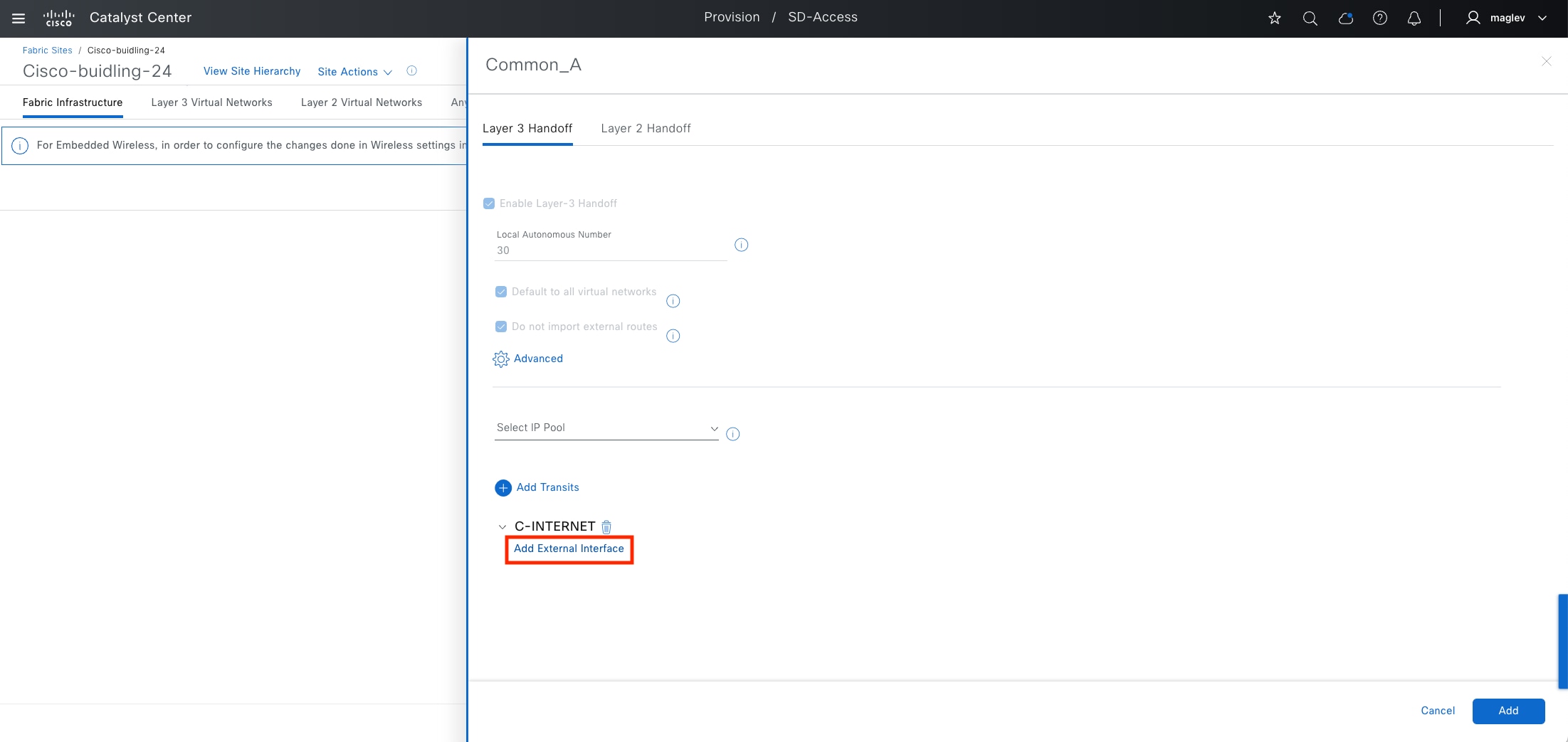
Step 5. Click Add External Interface to use the interface that is connected between the border and the peer device.
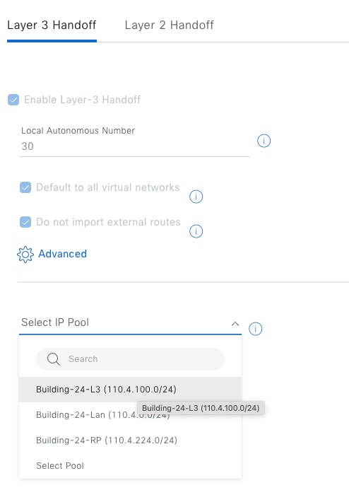
Step 6. Allocate IP addresses. Do either dynamic or manual allocation.
● To let the system dynamically allocate IP addresses through Catalyst Center, use Select IP Pool to add an IP pool.
IP address pool Building-24-L3 was defined in Procedure 2: Reserve IP pools for a fabric site.
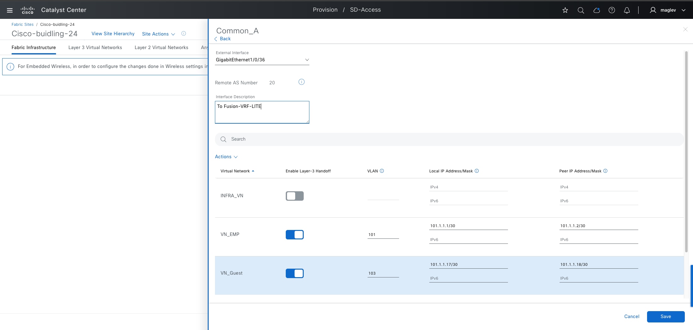
● To manually allocate IP addresses, configure the connected physical interface, VLAN, and customized IP address peers on the selected VNs VN_EMP and VN_Guest.
| Mandatory Fields |
Value |
| External Interface |
Gig 1/0/36 |
| VN_EMP |
VLAN 101, Local IP :101.1.1.1/30, Peer IP:101.1.1.2/30 |
| VN_Guest |
VLAN 103, Local IP:101.1.1.17/30, Peer IP :101.1.1.18/30 |
| Optional Fields |
Value |
| Interface Description |
To-Fusion-VRF-LITE |
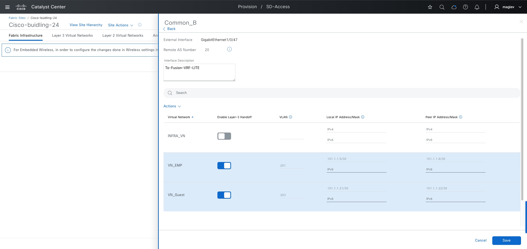
Tech tip: If layer 3 handoff is selected in the previous step, only VLAN information is required.
Step 7. Complete the workflow and provision to Common_A.
Step 8. Repeat the same steps on Common_B.
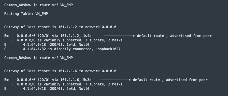
Note:
1. For LISP Pub/Sub external borders to work, a default route is required in the external border routing table. Ensure there is a default route in all the VRFs. DHCP with DNS servers can also connect through the internet and are considered as an unknown destination.
2. On internal borders, BGP routes learned from peer devices are imported to LISP and registered to a control plane. If shared services such as DHCP and DNS are connected through a data center, their IP addresses need to be advertised by peer devices.
Step 9. Validate Common_A and Common_B for VN VN_EMP.
a. Validate the default route in the routing table.
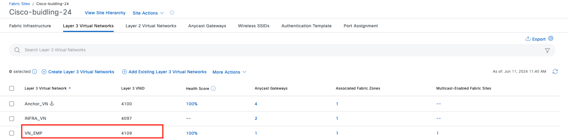
b. Validate the default route in the LISP database for VN VN_EMP.
Find the layer 3 instance ID of VN_EMP from the Layer 3 Virtual Networks tab.
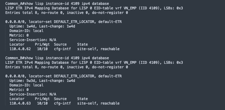
Step 10. Run the CLI.
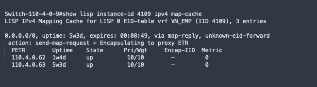
Step 11. Validate on the fabric edge node for VN VN_EMP.
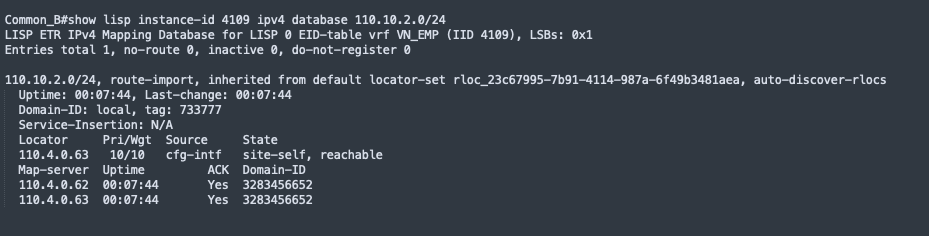
Note: For an internal border with a layer 3 handoff to a data center, shared services are advertised by peer devices through BGP.
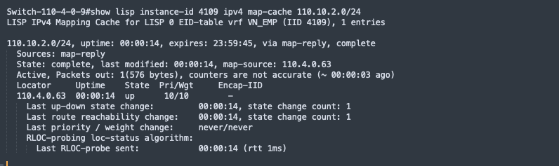
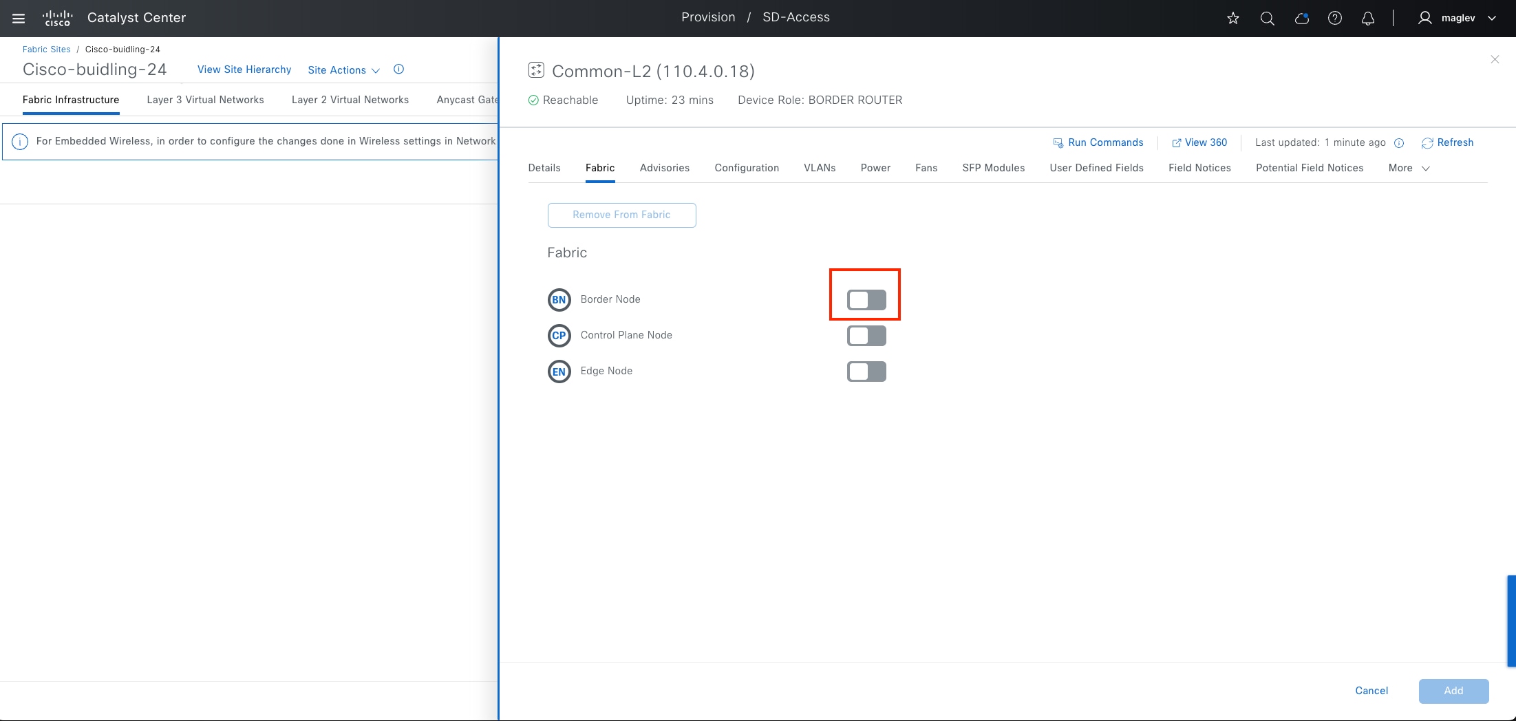
Provide fabric access for traditional layer 2 network using layer 2 handoff
The layer 2 border handoff allows the fabric site and the traditional network VLAN segment to operate using the same subnet. Communication between the two is provided across the border node with this handoff that provides a VLAN translation between fabric and nonfabric. Catalyst Center automates the LISP control plane configuration along with the VLAN translation, Switched Virtual Interface (SVI), CTS enforcement and the trunk port (allow all VLAN) connected to the traditional network on this border node.
Layer 2 handoff supported types include:
● Gateway outside fabric: Manually configured on a firewall or a layer 3 device connected to the border
● Gateway inside fabric: Configured on the layer 2 handoff border, and is the anycast gateway used in the layer 3 VN
It is recommended that the layer 2 border handoff device be dedicated and not colocated with any other function. The device must be operating in transparent mode for VLAN Trunking Protocol (VTP) to avoid unintended modification of the traditional network VLANs. The traditional network can use any VLAN except 1, 1002-1005, 2045-2047, and 3000-3500, which are either reserved in Catalyst Center or reserved for special use in Cisco software.
Follow the previous sections to onboard new device using the Discover workflow or LAN automation and provision the device in the Inventory window to the site Cisco-building-24.
Procedure 1. Provision layer 2 border with layer 2 handoff when a gateway is inside fabric
This procedure demonstrates adding the different types of layer 2 handoffs on a new border device Common-L2.
Step 1. From the top-left corner, click the menu icon and choose Provision > Fabric Sites, click the table view icon in the top right, click the Cisco-building-24 text link, then click the Fabric Infrastructure tab.
Step 2. In the slide-on pane, click Common-L2 then enable Border Node.
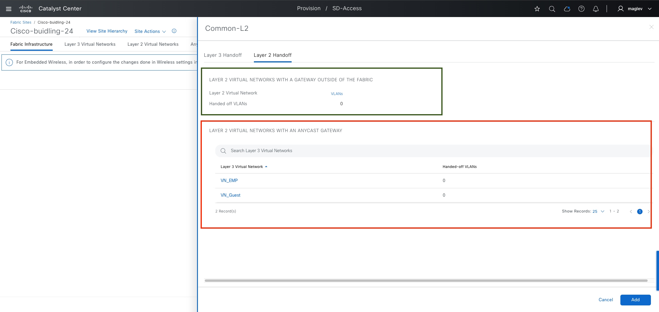
Step 3. In the slide-on pane, click the Layer 2 Handoff tab.
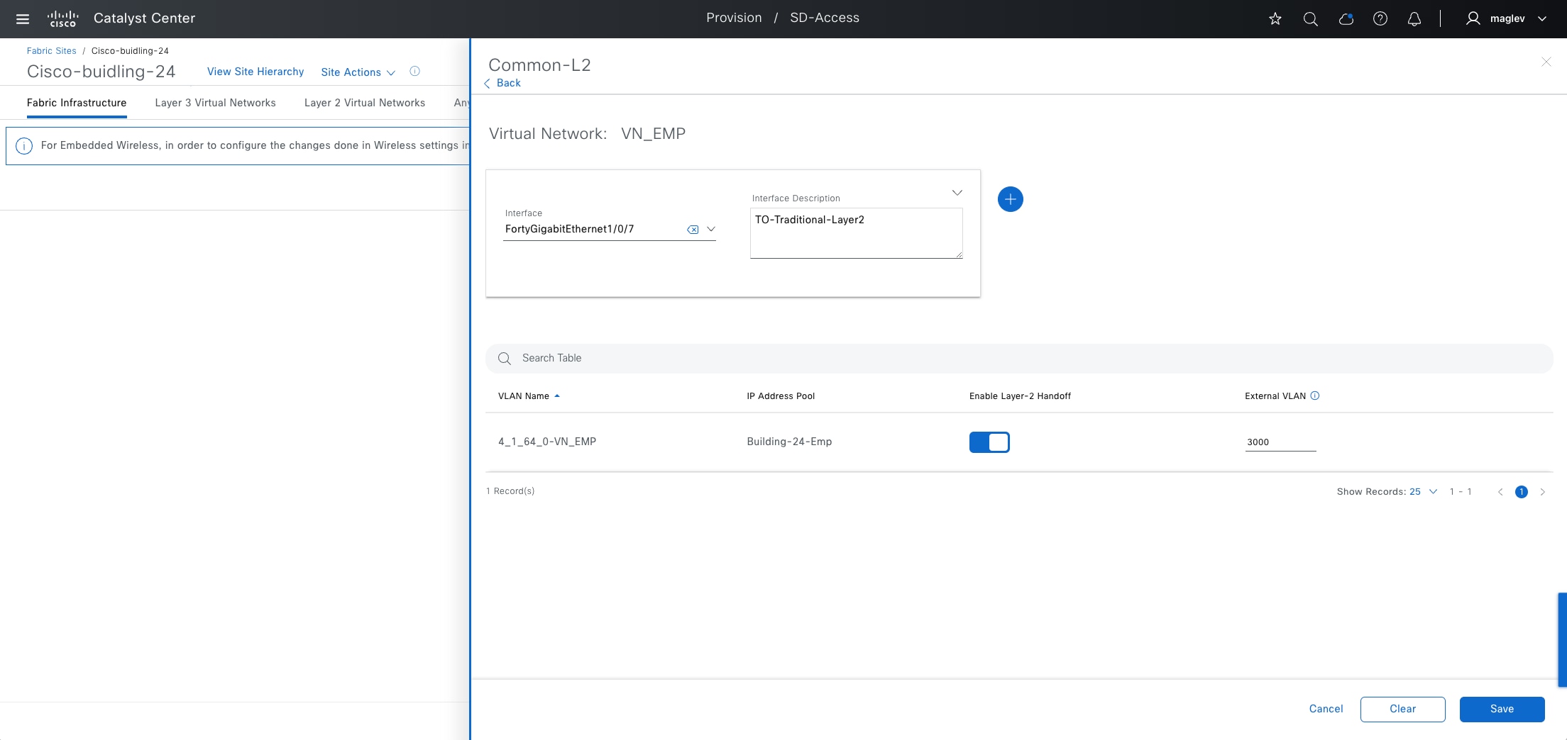
The configuration in the green box area is to automate the layer 2 handoff when a gateway is outside the fabric. The configuration in the red box area is to automate the layer 2 handoff when a gateway is inside the fabric.
Step 4. Configure the layer 2 handoff on VN EN_EMP and complete the workflow to deploy the task.
| Mandatory Field |
Value |
Use |
| Interface |
For 1/0/7 |
Connected to Traditional Layer 2 Network |
| External VLAN |
3000 |
Access VLAN of Traditional Layer 2 Network |
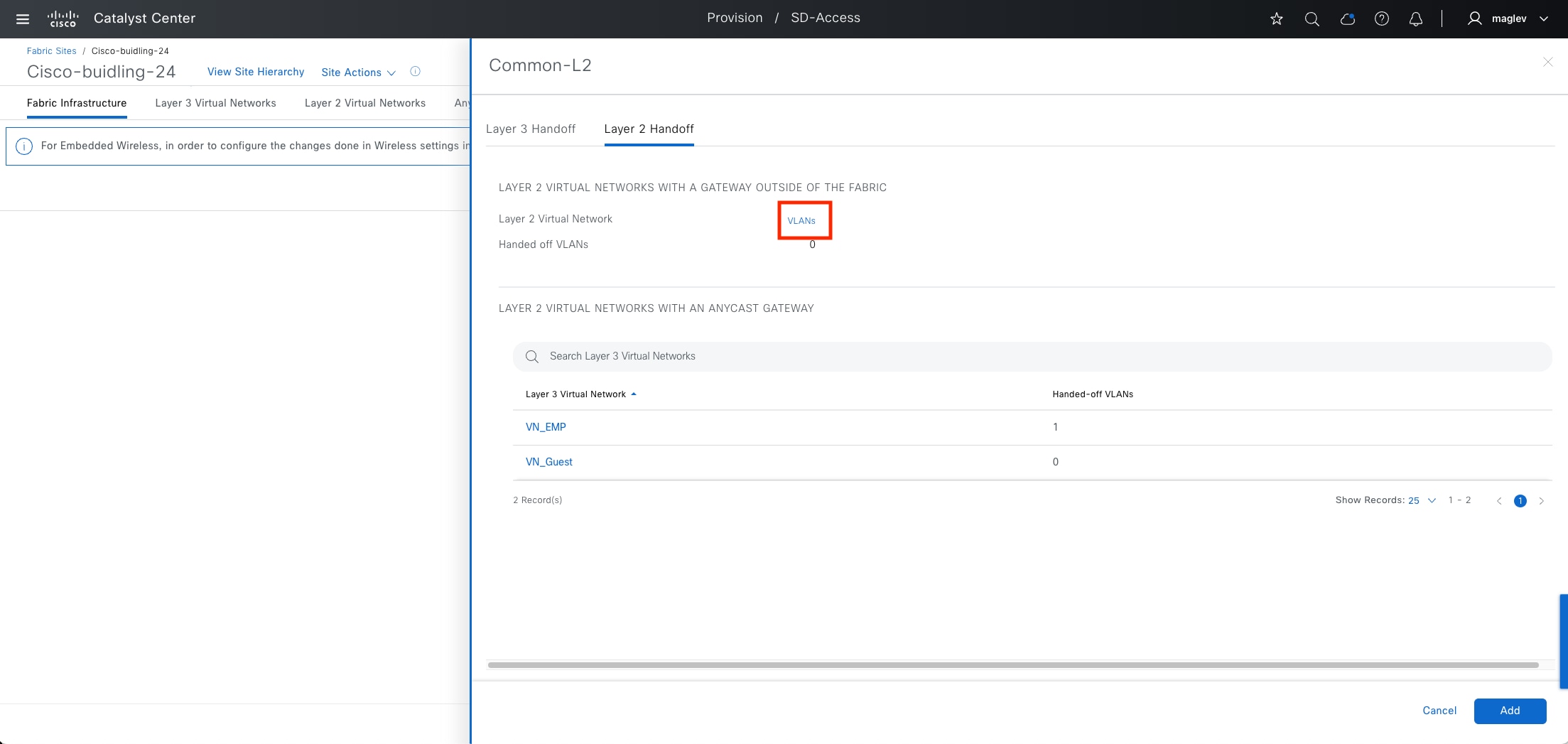
Procedure 2. Provision a layer 2 border with layer 2 handoff when a gateway is outside the fabric
When the gateway is outside the fabric, to extend the fabric overlay, a layer 2 only VN is required. In the previous section, a layer 2 only Guest network was configured.
Step 1. From the top-left corner, click the menu icon and choose Provision > Fabric Sites, click the table view icon in the top right, click the Cisco-building-24 text link, then click the Fabric Infrastructure tab.
Step 2. Choose Common-L2 > Layer 2 Handoff > VLANs.
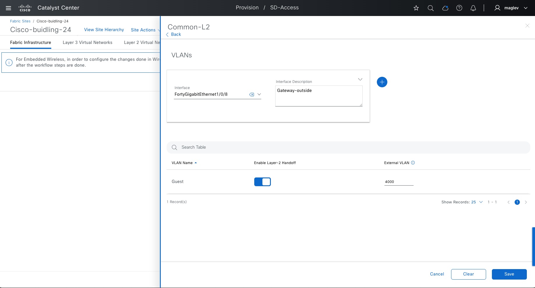
Step 3. For Guest, add an Interface and click Enable Layer-2 Handoff. External VLAN information is automatically provided.
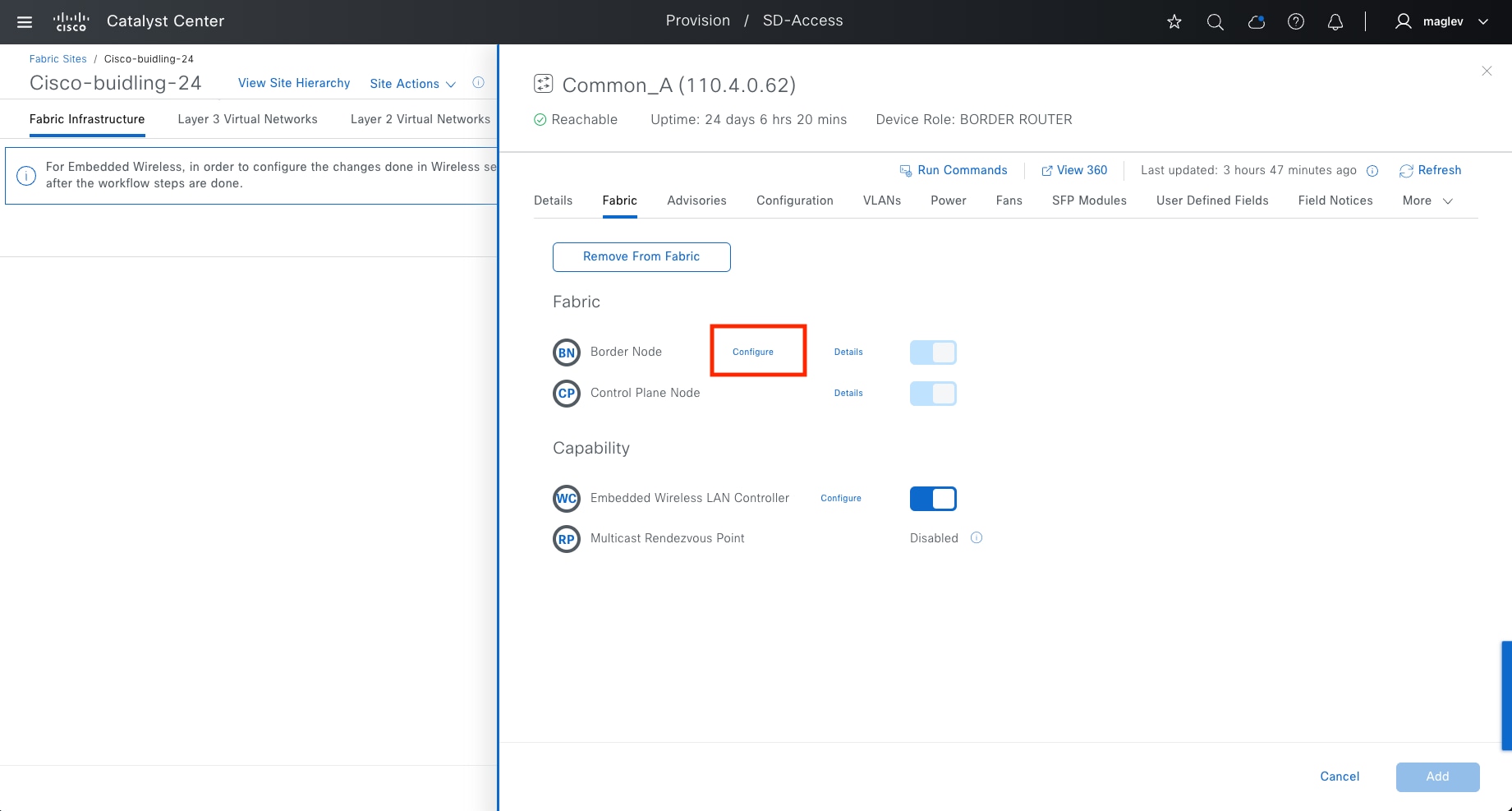
Step 4. Complete the workflow and deploy the task.
Note: Since the gateway is outside the fabric, Catalyst Center does not automate the gateway configuration.
Connect multiple fabric sites for crossing fabric communication using Cisco SD‑Access transit
A Cisco SD-Access transit connects multiple fabric sites and allows crossing fabric communications with SGT policy enforcement. Configure Cisco SD-Access transit on external borders (or anywhere borders). It is not supported for internal borders and layer 2 borders.
When connecting a fabric site to a Cisco SD-Access transit, all the VNs in this site are open to other fabric sites that are connected to the same Cisco SD-Access transit. Clients in the same VN are able to communicate in all the sites. Use SGT enforcement to block unnecessary traffic from other sites.
A Cisco SD-Access transit also provides options to enable sites to provide internet access for other sites that are connected to the same Cisco SD-Access transit. This is useful if some fabric sites do not have local internet access, or the local internet access is down.
In the previous section, Cisco SD-Access transit SDA was created with a control plane node. This procedure adds this Cisco SD-Access transit to Common_A and Common_B in Cisco-building-24.
Step 1. From the top-left corner, click the menu icon and choose Provision > Fabric Sites, click the table view icon in the top right, click the Cisco-building-24 text link, then click the Fabric Infrastructure tab.
Step 2. Click Common_A then in the slide-on pane next to Border Node, click Configure.
Step 3. Click Add Transits > SDA:SDA.
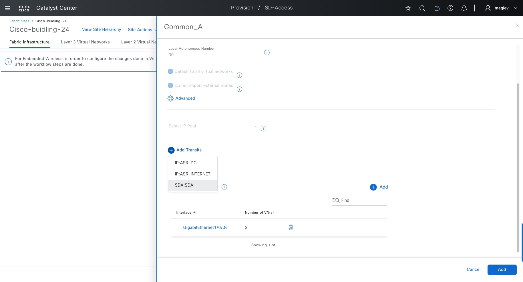
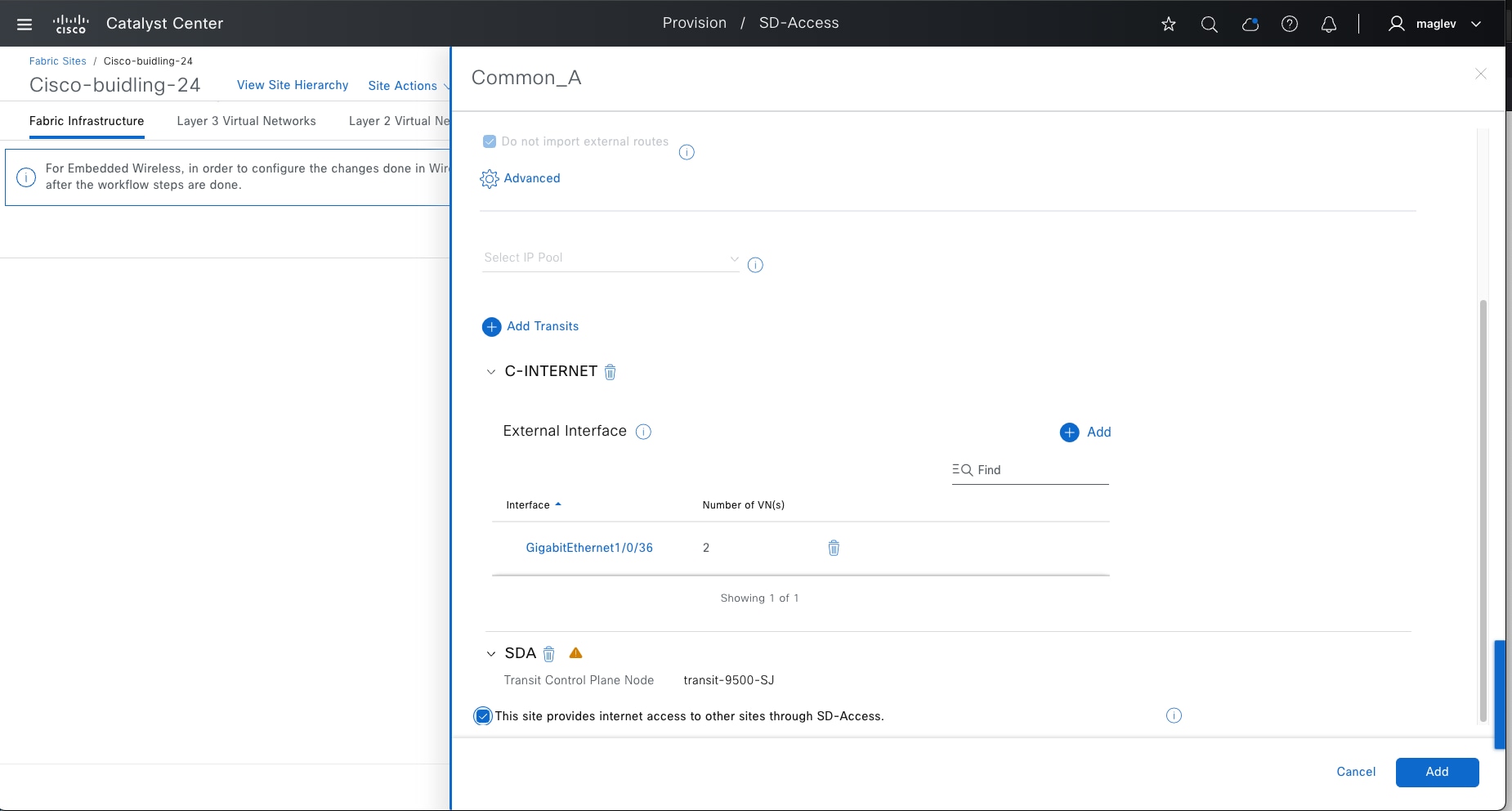
Step 4. Check the This site provides internet access to other sites through SD-Access check box then click Add.
Step 5. Complete the workflow and deploy the task.
Step 6. Repeat the same steps for Common_B and deploy the task.
Note: Verify that all the borders connected to Cisco SD-Access transit have the same configuration for providing internet access to other sites.
Step 7. Validate on the transit control plane.
1. Confirm LISP session status between Common_A, Common_B, and the transit control plane.
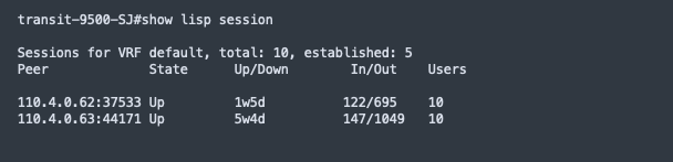
2. Common_A and Common_B are registered as the default egress tunnel router (ETR) on the transit control plane to provide internet connection to other sites.
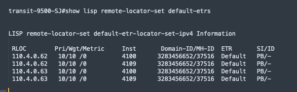
Note: Only This site provides internet access to other sites through SD-Access feature is enabled on the borders, and the border node is listed under this command on the transit control plane.
3. Validate that the client subnet is registered in the transit control plane, replace ipv4 with ipv6 in the command if dual stack is enabled.
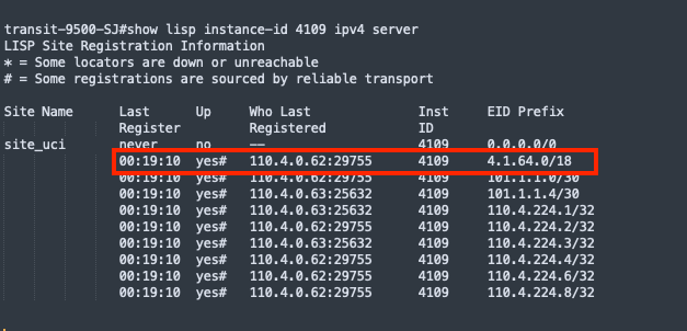
Step 8. Validate on another site (FiaB site) that does not have local internet and is connected to the Cisco SD-Access transit.
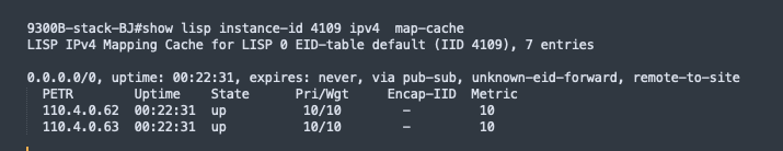
This section focuses on configuring native multicast for VN_EMP in the fabric site Cisco-building-24, enabling multicast for wireless, and configuring native multicast over Cisco SD-Access transit.
Native multicast requires a PIM SSM underlay configuration, which has been done through LAN automation in the previous section. If LAN automation is not used, these configurations need to be configured manually on all fabric devices such as fabric borders, intermediate nodes, and fabric edges. Deploy the configuration using the Catalyst Center CLI template.
This design and deployment guide does not discuss templates. See the Catalyst Center User Guide, section ‘Create Templates to Automate Device configuration Changed’.
Sample template configuration:
● layer3_interface: all underlay layer 3 interfaces
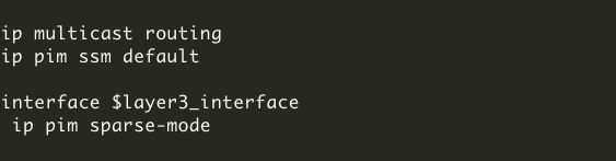
Procedure 1. Configure native multicast within a fabric site
Step 1. From the top-left corner, click the menu icon and choose Provision > Fabric Sites, click the table view icon in the top right, click the Cisco-building-24 text link, then click the Fabric Infrastructure tab.
Step 2. Click Site Actions > Configure Multicast.
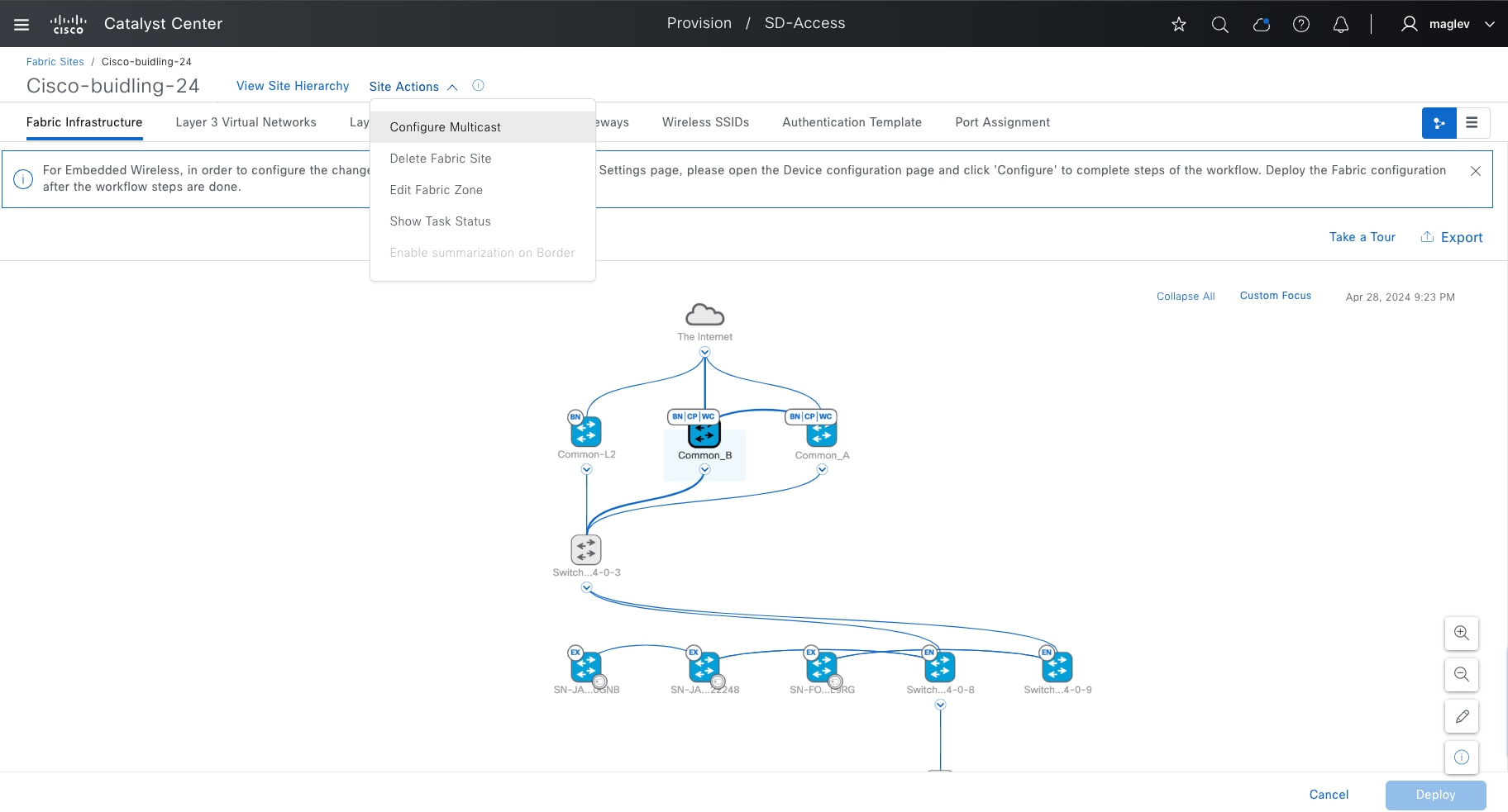
Step 3. Choose Native Multicast then click Next.
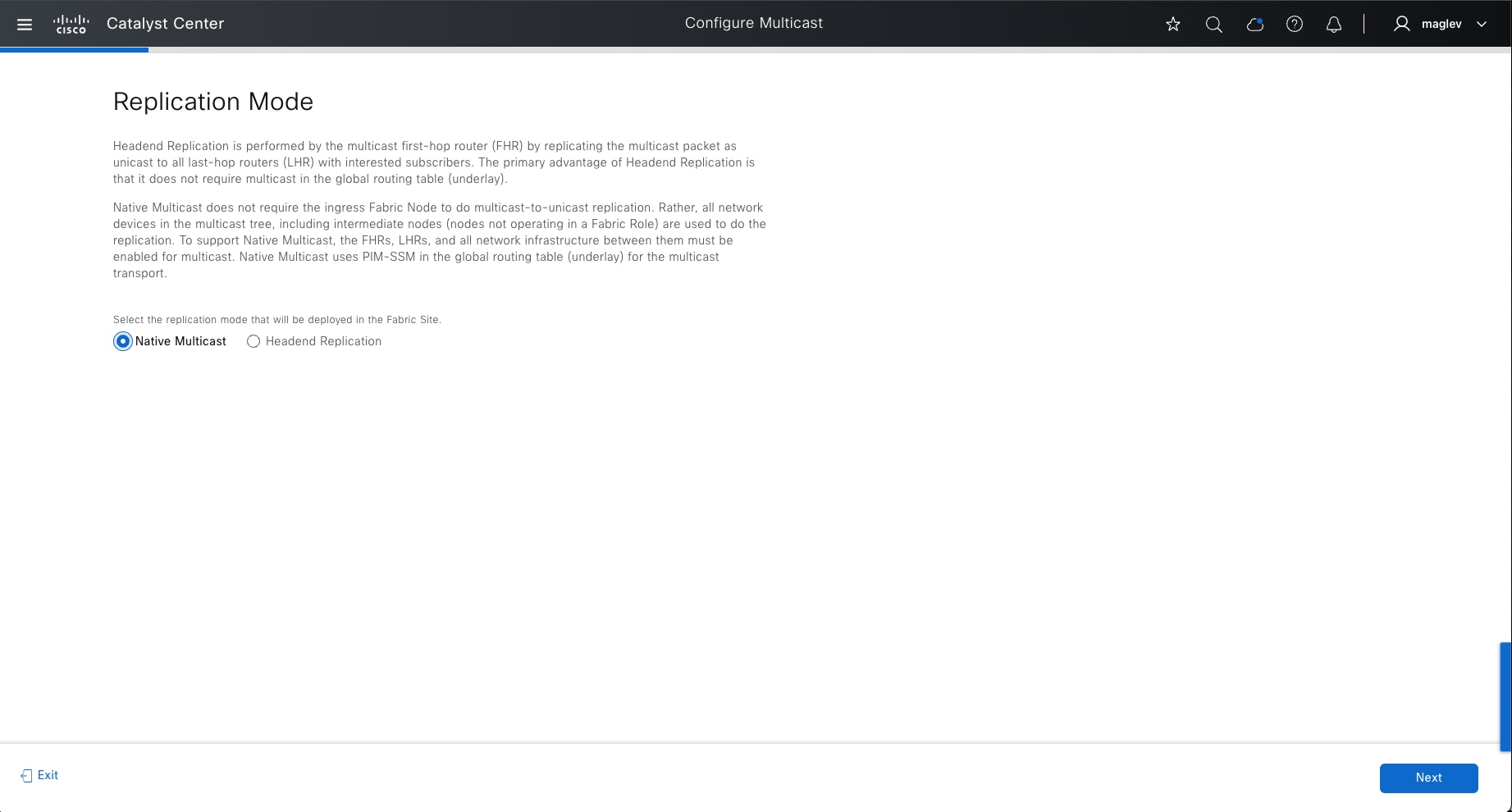
Step 4. Choose VN_EMP then click Next.
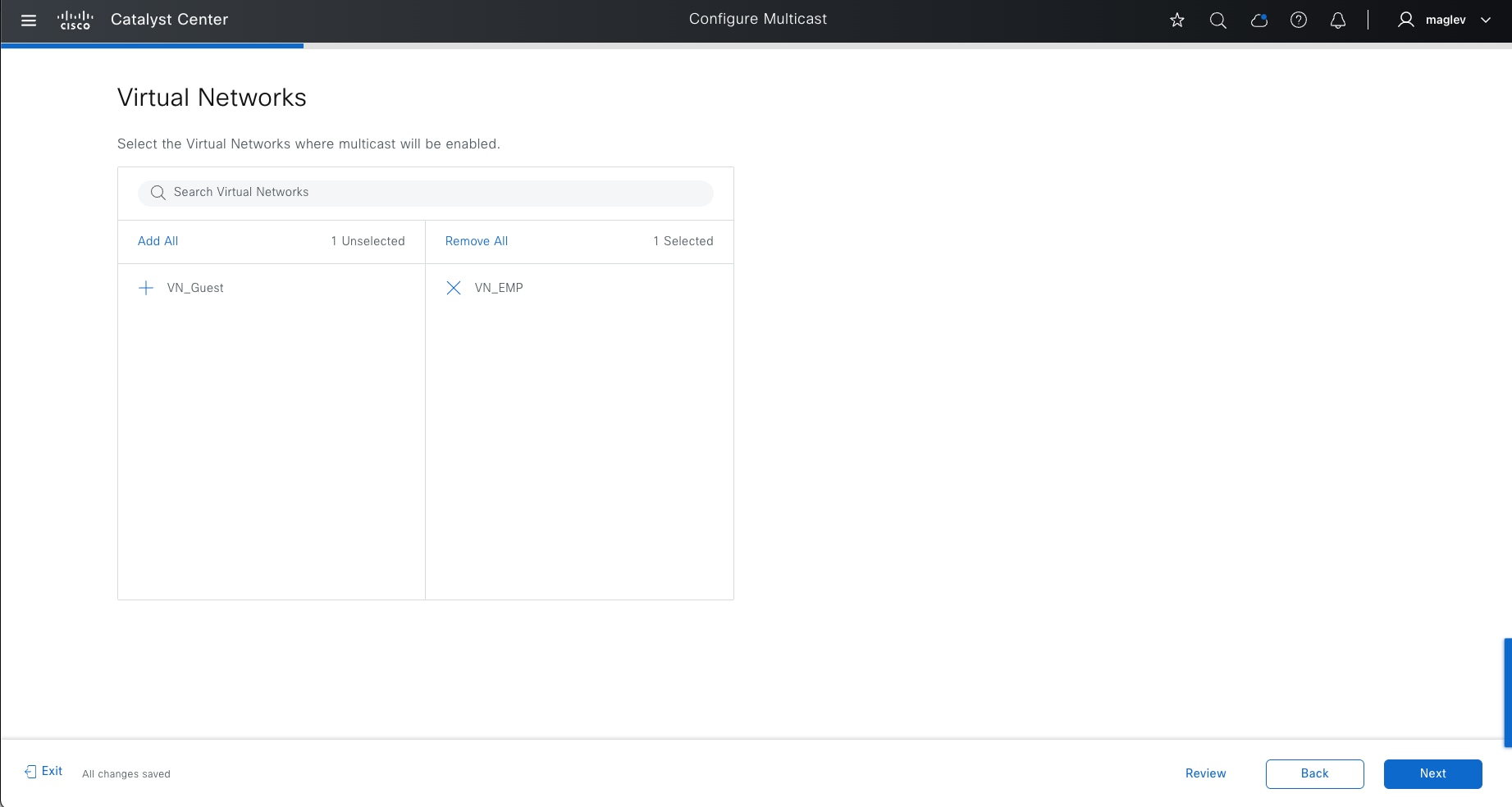
Step 5. Add the predefined IP Address Pool then click Next.
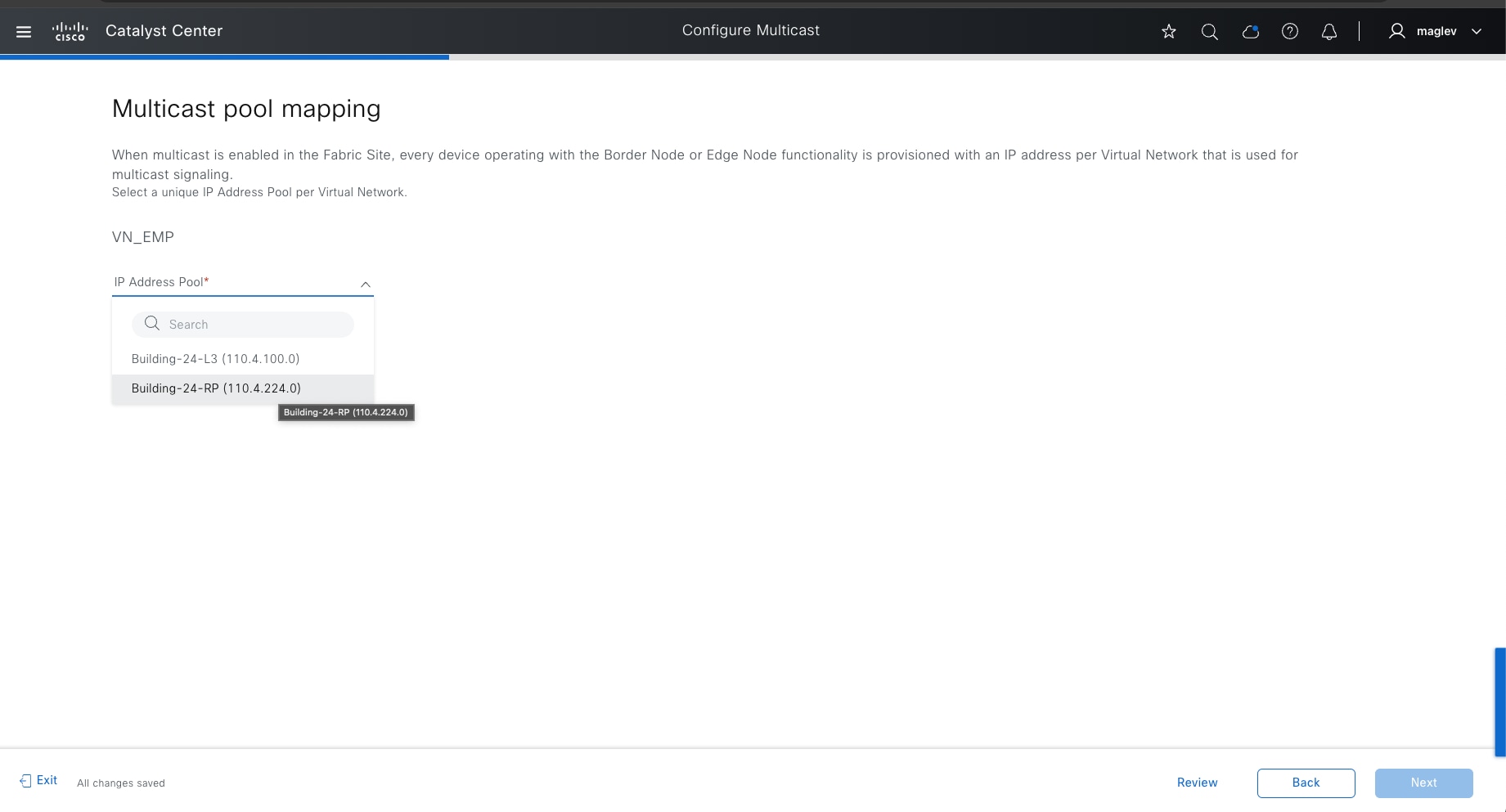
Tech tip: If multicast is enabled on multiple VNs, each VN must have a unique IP address pool.
Step 6. Choose Any Source Multicast (ASM) mode. ASM mode configures RP.
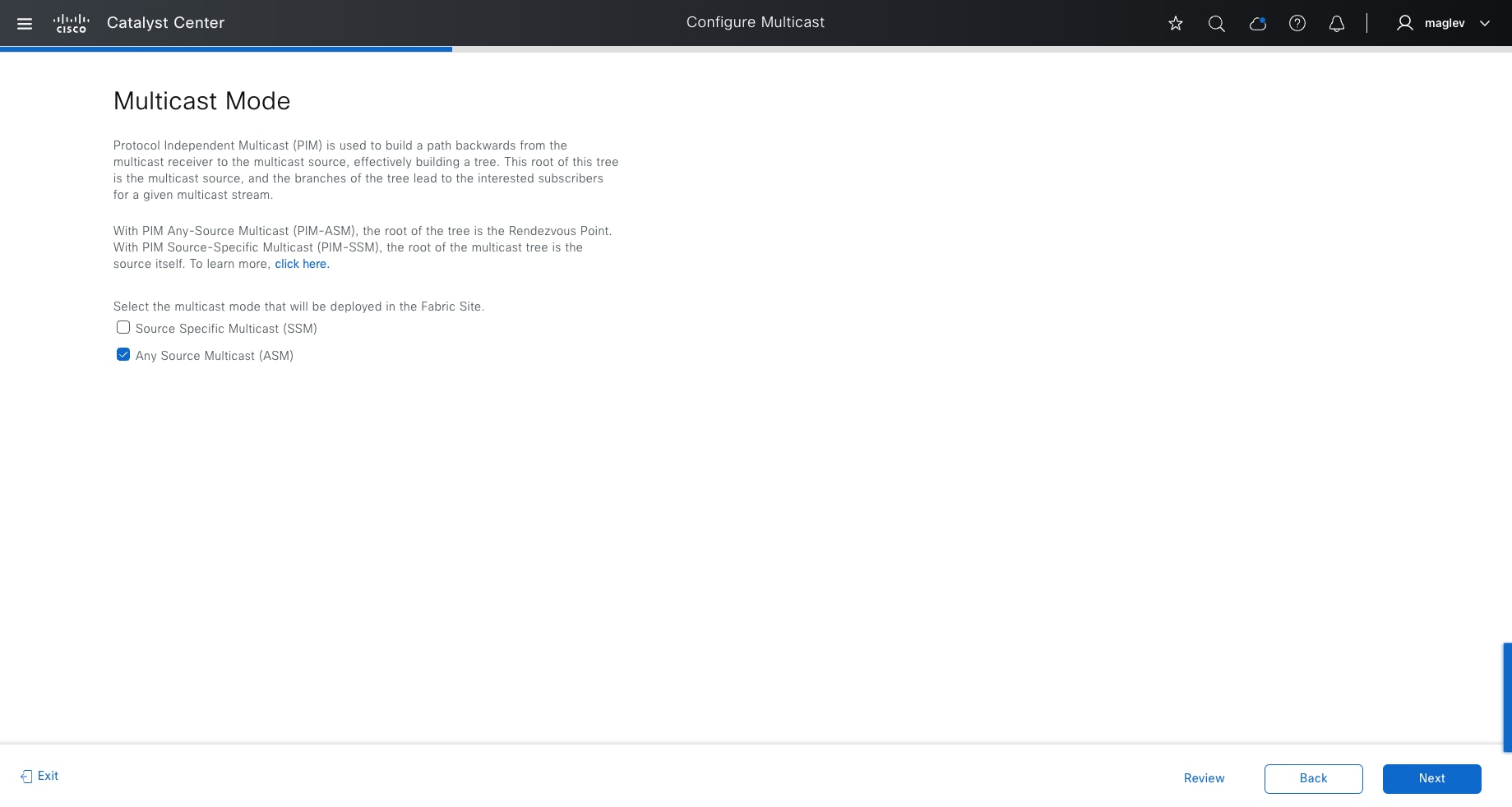
Step 7. Configure RP mapping and mapped RP group (optional) then complete the workflow to deploy the task.
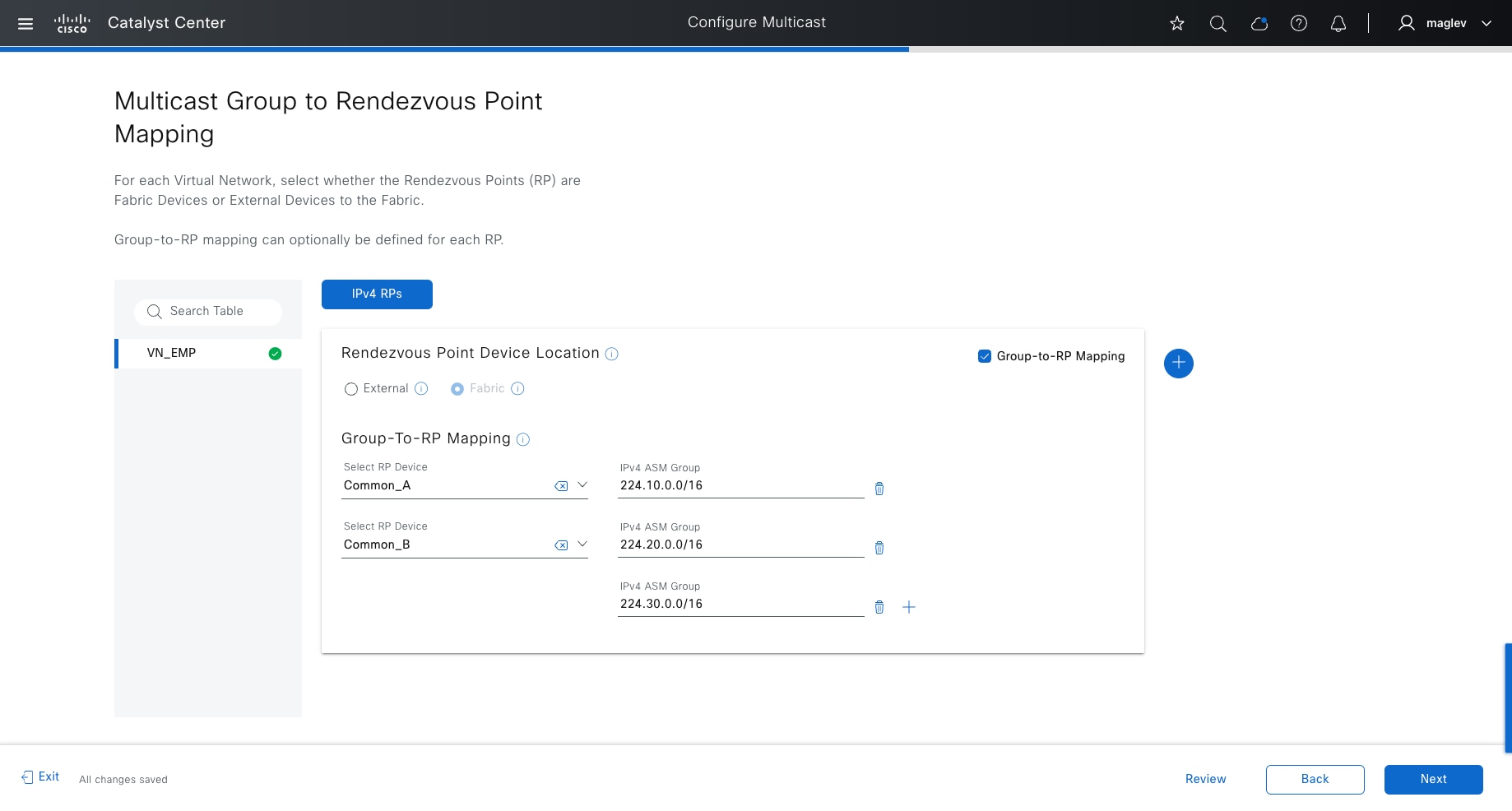
Note:
1. If the RP is inside fabric, RP capability can be enabled in either border devices or edge devices. The combination of border devices and edge devices is not supported. If the RP is enabled on border devices, dual RP configurations with the same ASM groups is supported. If the RP is enabled on edge devices, only a single RP is supported. If a RP is inside the fabric, only one RP for each VN can be added. It is recommended to configure a RP on border nodes instead of edge nodes because border nodes are higher-end platforms with more CPU, RAM and ASIC resources.
2. If the RP is outside the fabric, multiple external RPs can be added with different ASM group mapping.
3. Group-to-RP Mapping is optional. If the option is not checked, the RP is mapped to all multicast groups.
After the configuration is pushed to all the fabric devices. In the topology view, Common_A and Common_B, which are configured as the RP, are marked with the RP fabric role.
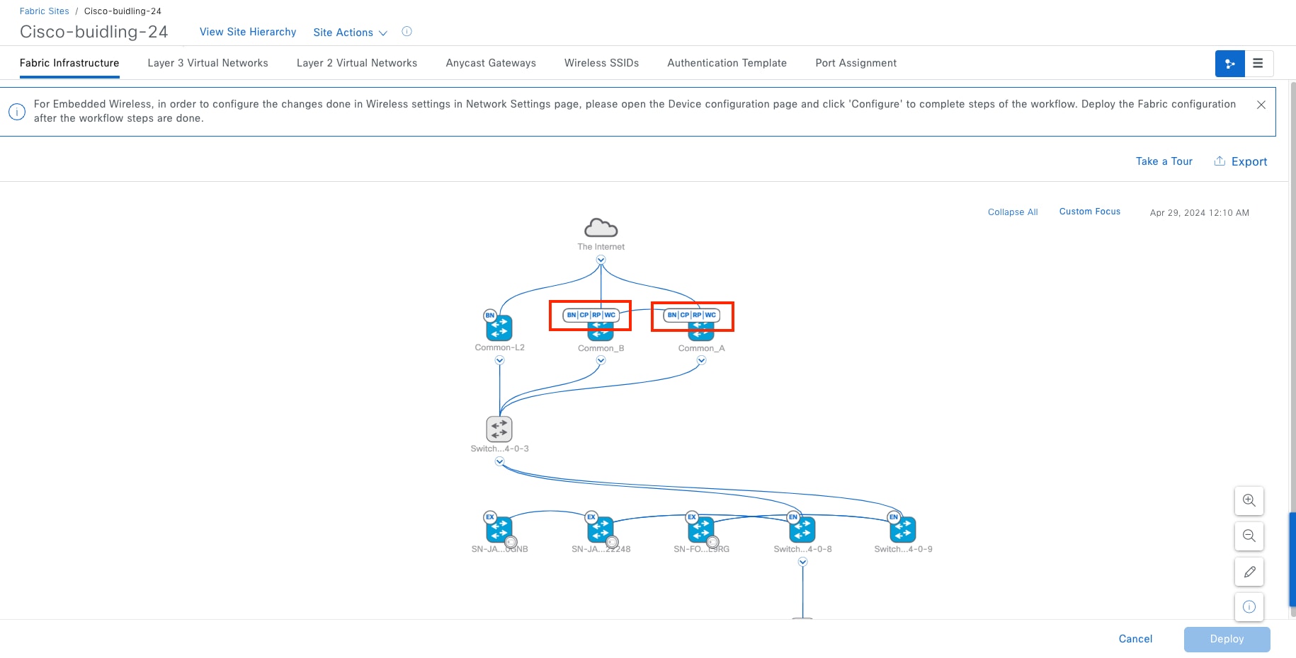
Step 8. Click Common_A or Common_B to confirm that the border Capability status for Multicast Rendezvous Point is Enabled.
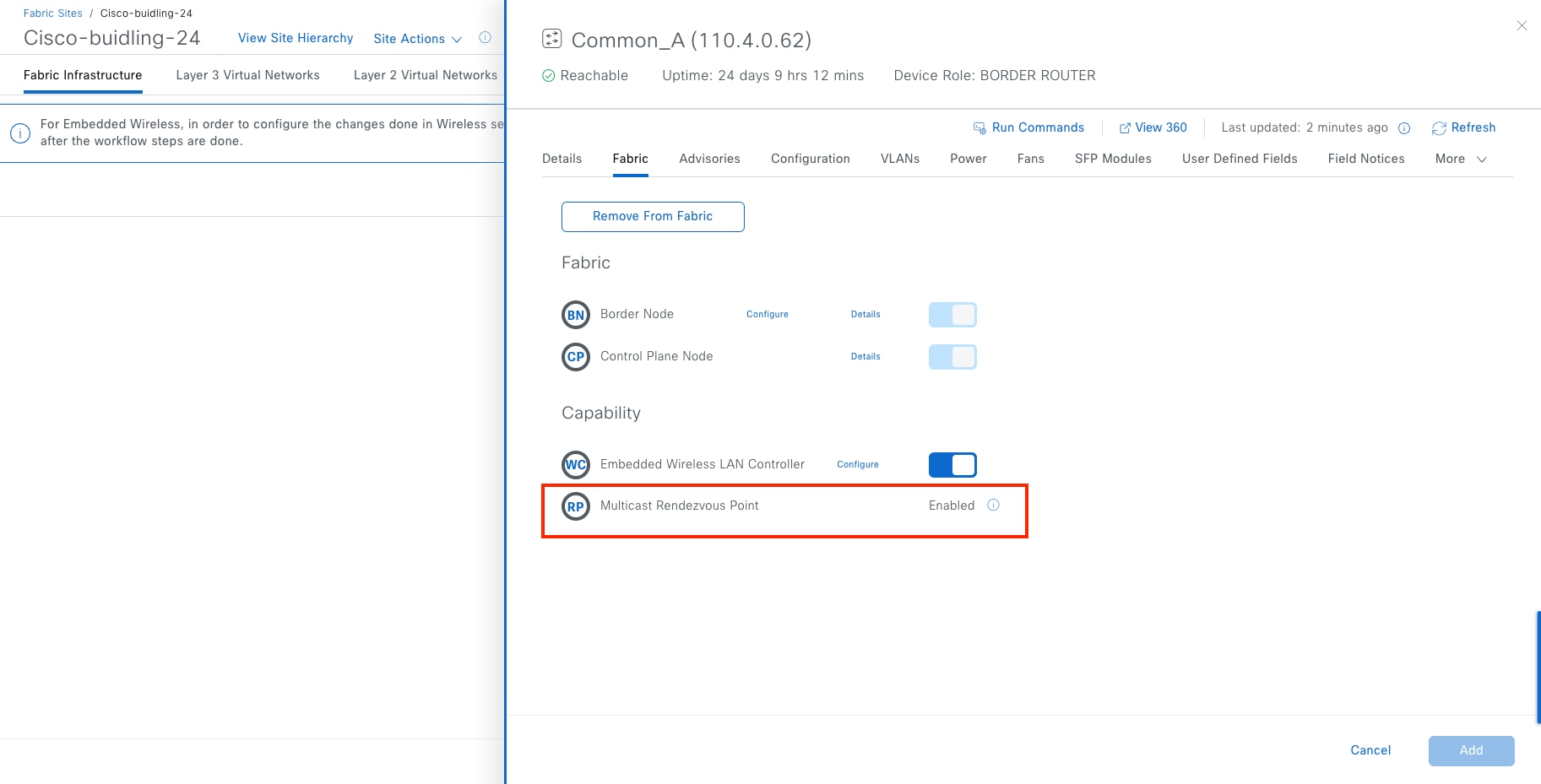
Step 9. Enable multicast for Cisco SD-Access wireless. Navigate to the Wireless SSIDs tab then click Enable Wireless Multicast to enable Global Multicast mode and Internet Group Management Protocol (IGMP) snooping globally on the wireless controller.
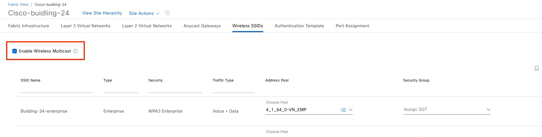
Procedure 2. Enable native multicast over Cisco SD-Access transit
Native multicast is supported in multisite Cisco SD-Access transit topology with LISP Pub/Sub. Multicast receivers in fabric sites that have native multicast enabled in the same VNs and connected to Cisco SD‑Access transit are able to receive multicast traffic from the same source.
An RP can be configured outside the fabric and all the fabric sites point to the common RPs.
Step 1. From the top-left corner, click the menu icon and choose Provision > Transits then click the table view icon in the top right.
Step 2. Check SDA in the list, then click More Actions > Edit Transit.
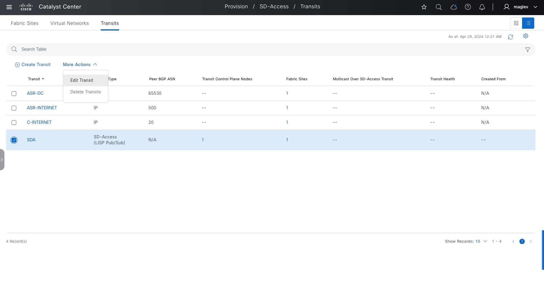
Step 3. Click Edit next to Transit Name and Type then click Next.
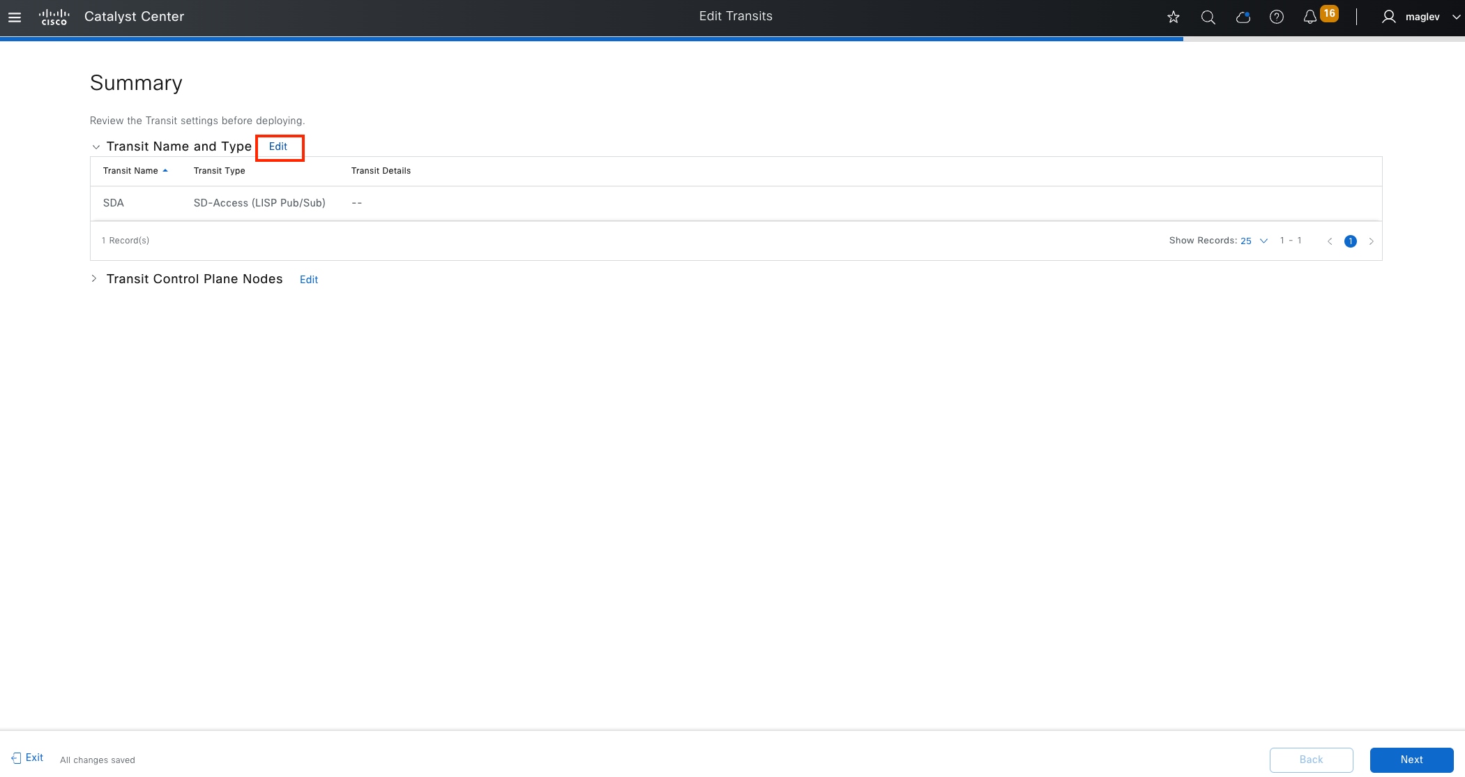
Step 4. Check the Native Multicast Over SD-Access Transit check box then click Next to complete the workflow to deploy the task.

Step 5. From the top-left corner, click the menu icon and choose Provision > Fabric Sites, click the table view icon in the top right, click the Cisco-building-24 text link, then click the Fabric Infrastructure tab.
Step 6. Click Common_A in the slide-in pane then click Configure next to Border Node.
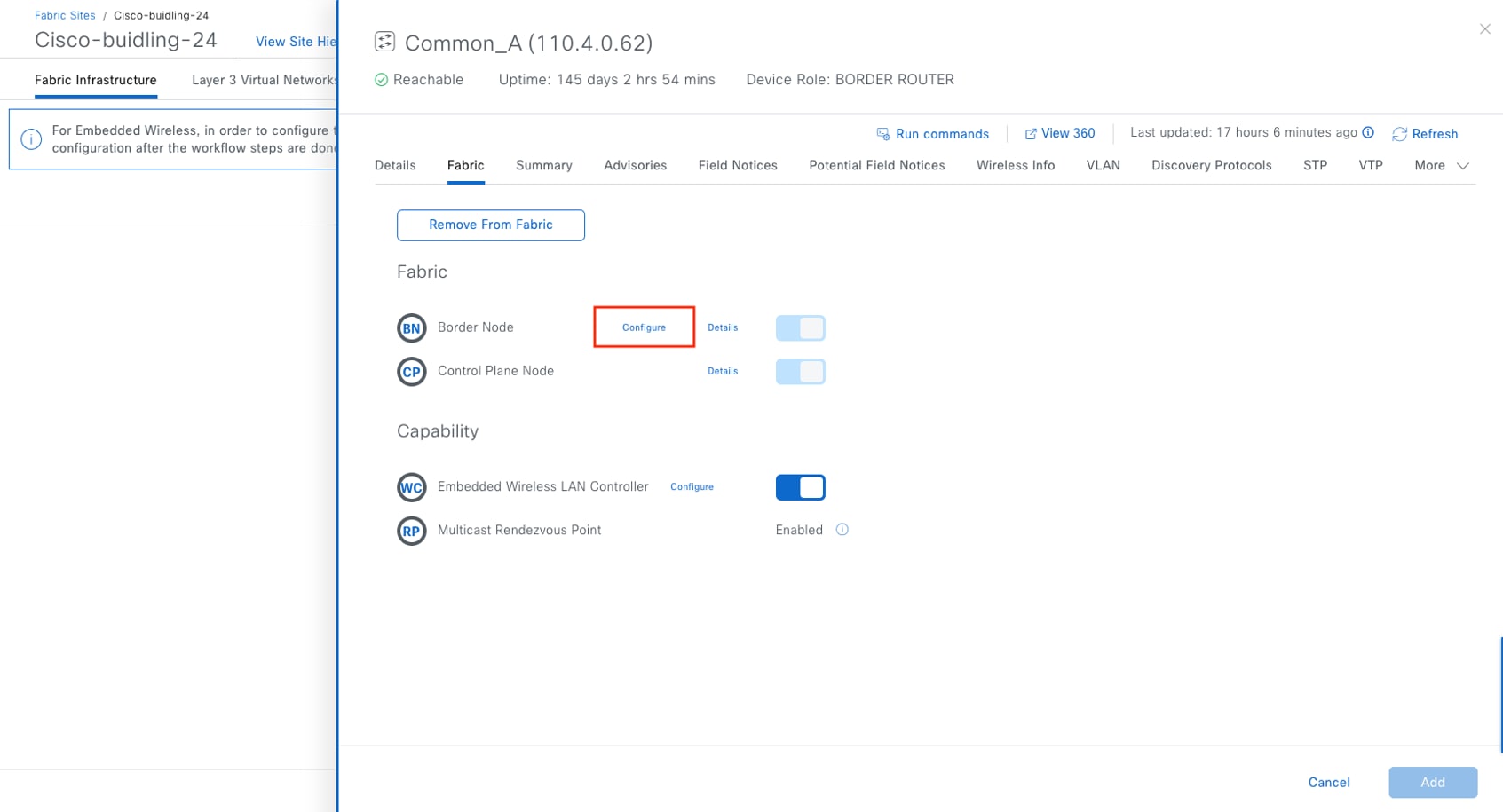
Step 7. Click Advanced.
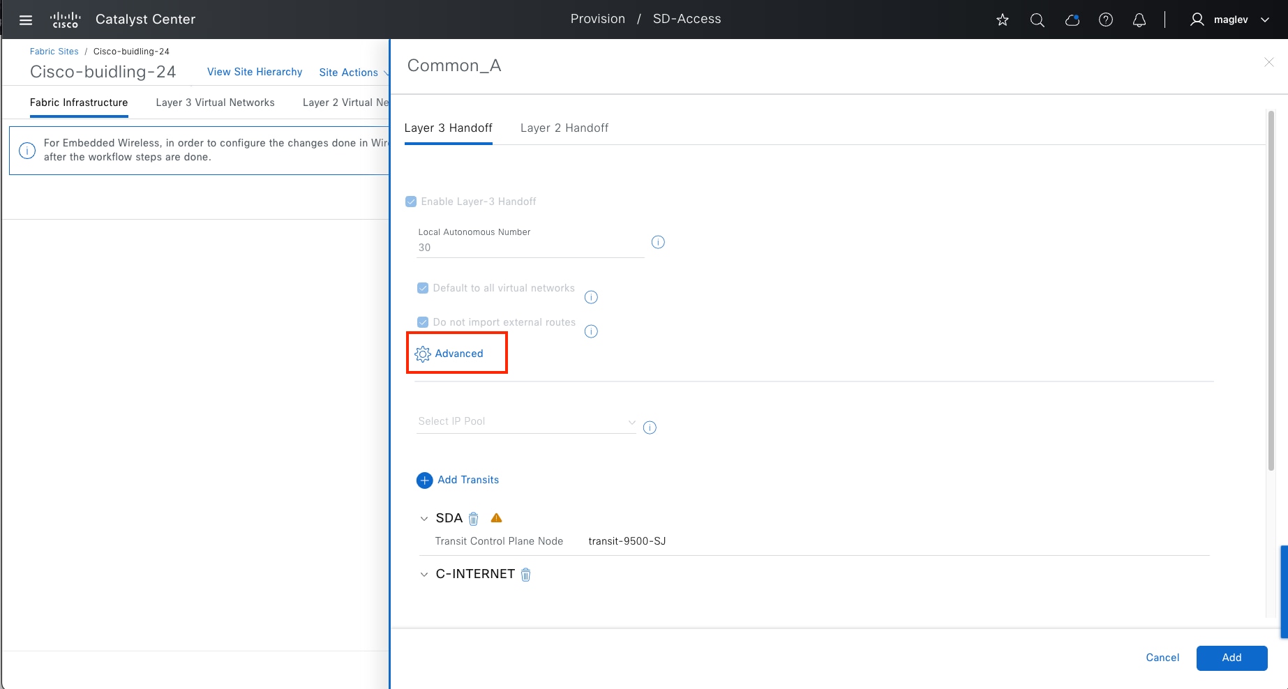
Step 8. Check the Enable Multicast Over SD-Access Transit option, then click Apply to complete the workflow and deploy the task.
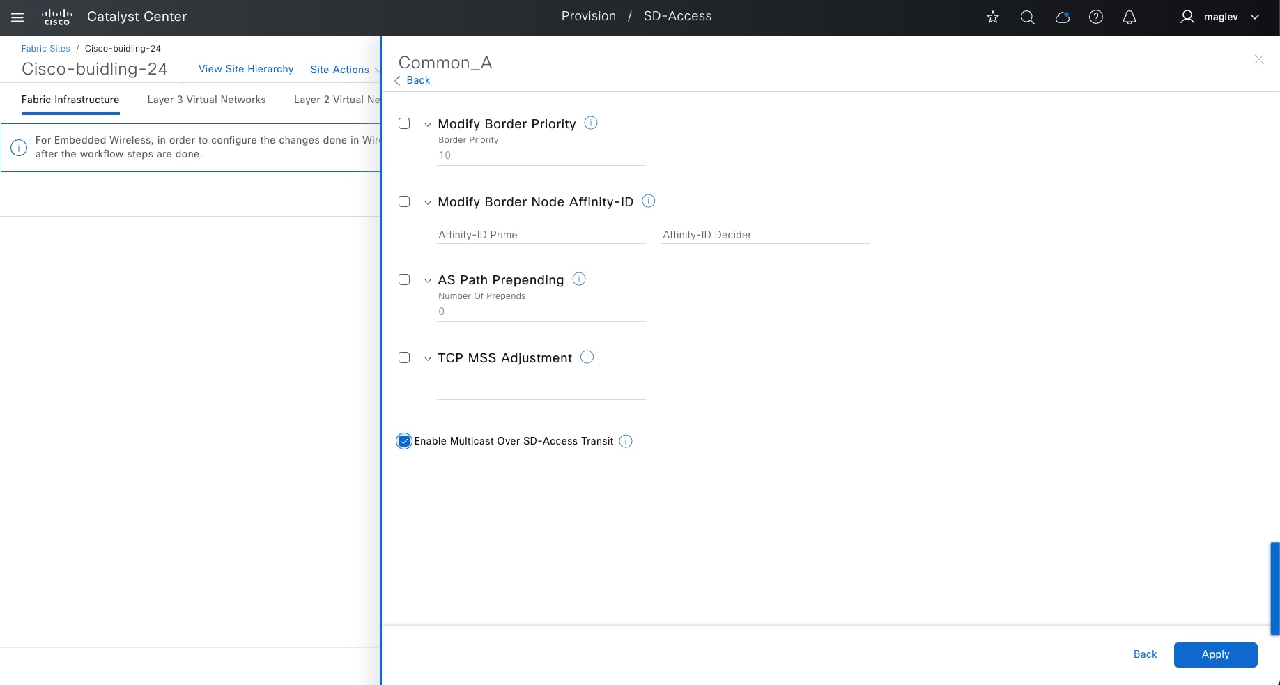
Step 9. Repeat the same steps for the Common_B border.
Use advanced fabric features on fabric borders
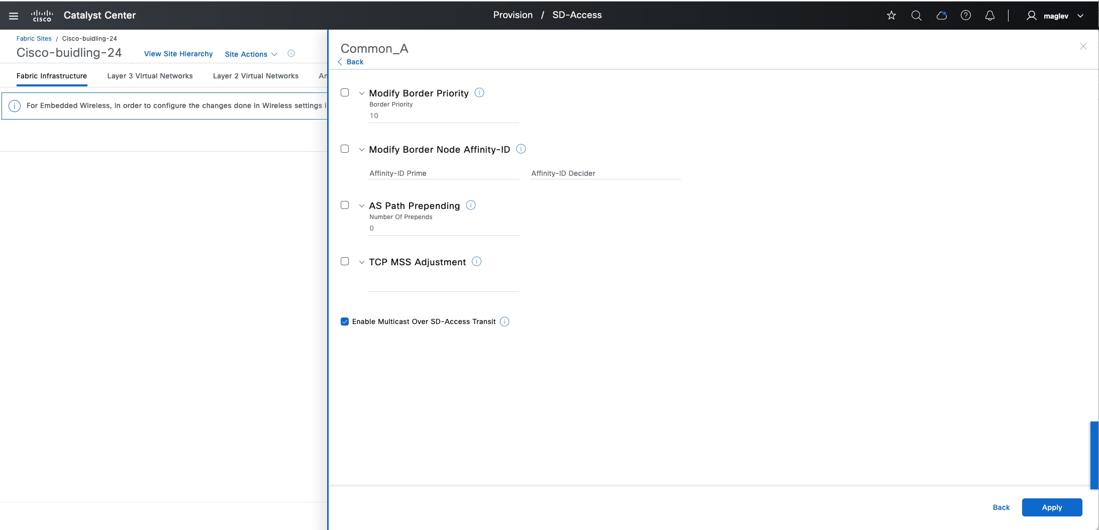
Border priority
Catalyst Center provides the capability to select a border node to egress the fabric network traffic.
Priority values can be set between 1 and 9 where 1 is the highest priority and 9 is the lowest. A lower number border is the preferred. By default, if a priority value is not set, the border is assigned a priority value of 10. If border priorities are not set, or are the same across borders, traffic is load balanced across the border nodes.
The border priority is a LISP configuration that can be modified in day-n operations without removing devices from the fabric. The priority value set for a border is applicable to all the virtual networks that are handed off from that border. If a Cisco SD-Access transit interconnects the fabric sites, an external border with the lowest priority is chosen to send traffic to external networks.
This option is available on all three types of layer 3 borders.
Affinity-ID
Affinity-ID is used to select the closest remote default-ETR (default route with internet service) reachable over Cisco SD-Access transit when local internet is not available. All fabric sites that are participating need to configure Affinity-ID in the borders that have Cisco SD-Access transit configured. By default, this feature is disabled.
Affinity-ID contains Prime (X) value and Decider(Y) value. You can configure the prime and decider values between 0 and 2147483647. When a participating border receives an Affinity-ID value from borders in other sites. It calculates the Affinity value:
● Relative prime value: abs (X-X’) A lower relative prime value indicates a higher preference.
● Relative decider value: abs (Y-Y’) When the prime value is the same for two border nodes, the decider value is used as a tiebreaker to determine the border node preference.
Affinity-ID is a LISP configuration that can be modified in day-n operations, and it is applicable to all VNs that require internet services. When Affinity-ID is configured, border priority is superseded to determine the preference. If the calculated Affinity value is the same, border priority is used to determine the border node preference.
This option is only available on an external border or an anywhere border.
A typical use case in a multisite over SD-Access transit deployment sets an Affinity-ID based on geolocation or distance. Multiple sites provide internet access. An Affinity‑ID based on distance can be set to select the closed remote border for internet traffic.
AS-Path Prepending
The AS-Path Prepending technique is a BGP configuration on border nodes and advertised to eBGP peer devices to select a fabric border for ingress traffic. By default, this option is disabled. The configuration can be modified in day-n operations, and configured to advertise to all eBGP peers, which are configured through the layer 3 handoff workflow.
This option is available on all types of layer 3 borders.
TCP MSS Adjustment
Cisco SD-Access uses fabric VXLAN encapsulation for transporting endpoint data. This encapsulation adds 50 bytes of overhead to the original packet and cannot be fragmented. For deployments that are unable to accommodate a jumbo MTU, use the TCP MSS Adjustment feature to enforce ingress MTU on TCP sessions.
The TCP MSS Adjustment feature can be configured on a fabric anycast gateway or layer 3 handoff interfaces. When enabled on borders, all the layer 3 interfaces get this value applied.
This option is available on all three types of layer 3 borders and can be modified during day-n operations.
Anchor a VN
As explained in the previous MSRB section, consider VN anchoring:
● Egress preference for each VN: Specify the ingress and egress fabric site for a given VN, for instance, guest traffic to a DMZ.
● Same subnet across multiple fabric sites: Preserve and conserve IP address space.
Tech tip:
1. The border and control plane nodes can be distributed or colocated at the anchor site.
2. A VN can be anchored at only one fabric site.
3. Seamless wireless roaming between anchor site and anchoring sites is not supported.
4. Catalyst 9800 wireless controllers supports up to 16 control plane node pairs, make sure to not configure too many anchor sites.
5. Changing a regular VN to an anchor VN is not supported. VN anchoring configuration is only for greenfield VNs.
This section demonstrates the how to create an anchor VN with its associated IP address pools in the fabric site Cisco-building-24 and used in another fabric site named Cisco-building-9.
Procedure 1. Create an anchor VN
Step 1. From the top-left corner, click the menu icon and choose Provision > Virtual Networks, change to the table view then click Create Layer 3 Virtual Networks.
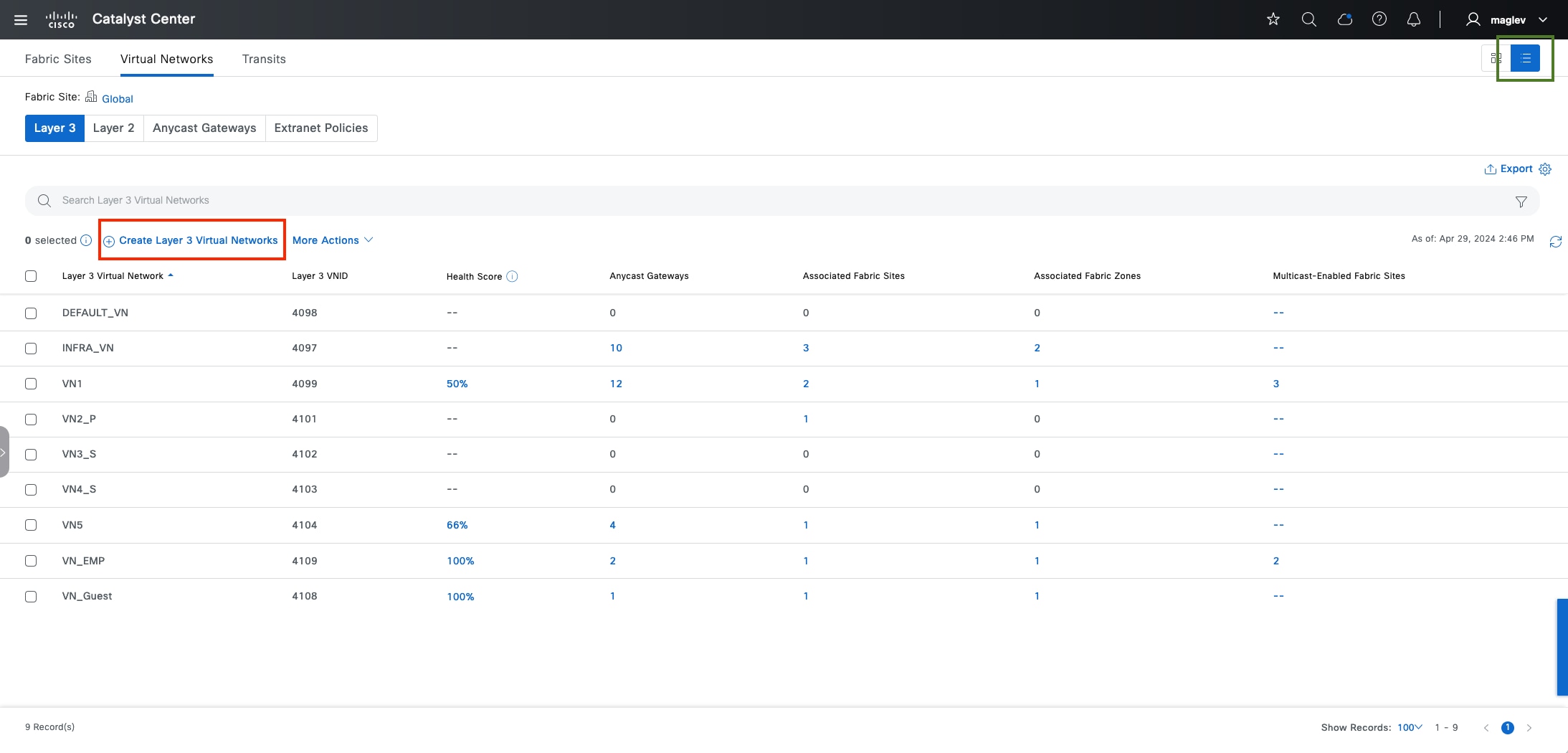
Step 2. Create the new VN Anchor_VN then click Next.
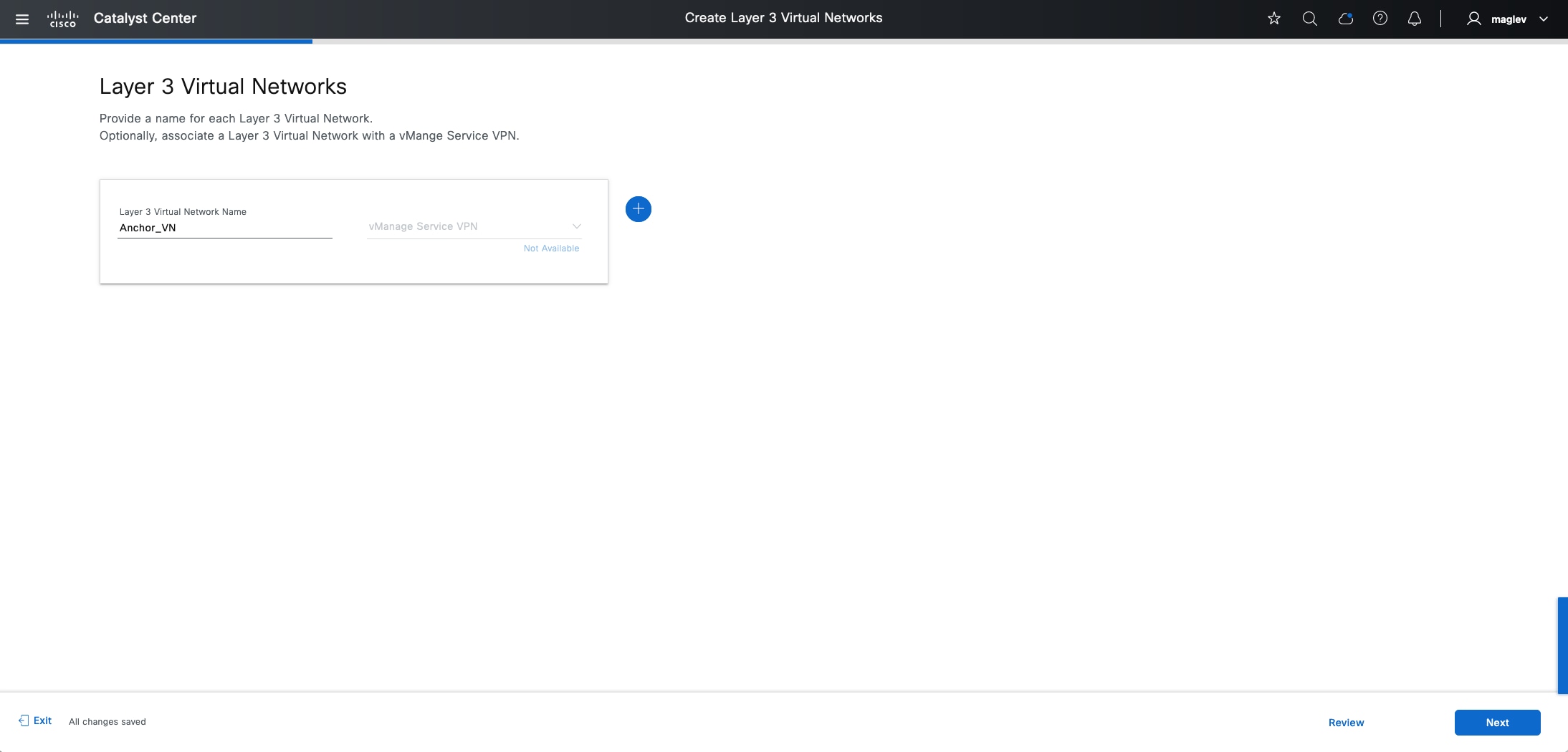
Step 3. Associate Cisco-building-24 to an anchor site then click Next to complete the workflow and deploy the task.
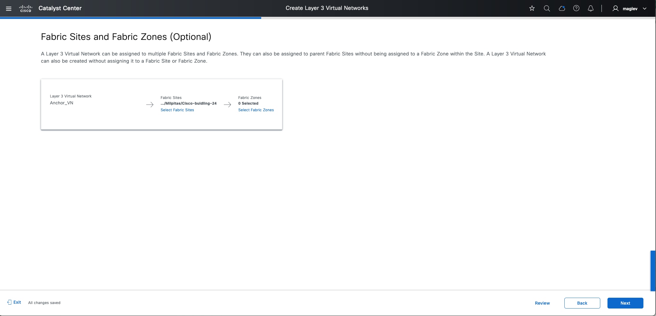
Note: Do not associate the fabric zone before enabling Anchor_VN.
Step 4. Go back to the Virtual Networks window, check the new VN Anchor_VN check box then click More Actions > Anchor to a Fabric Site and deploy the task.
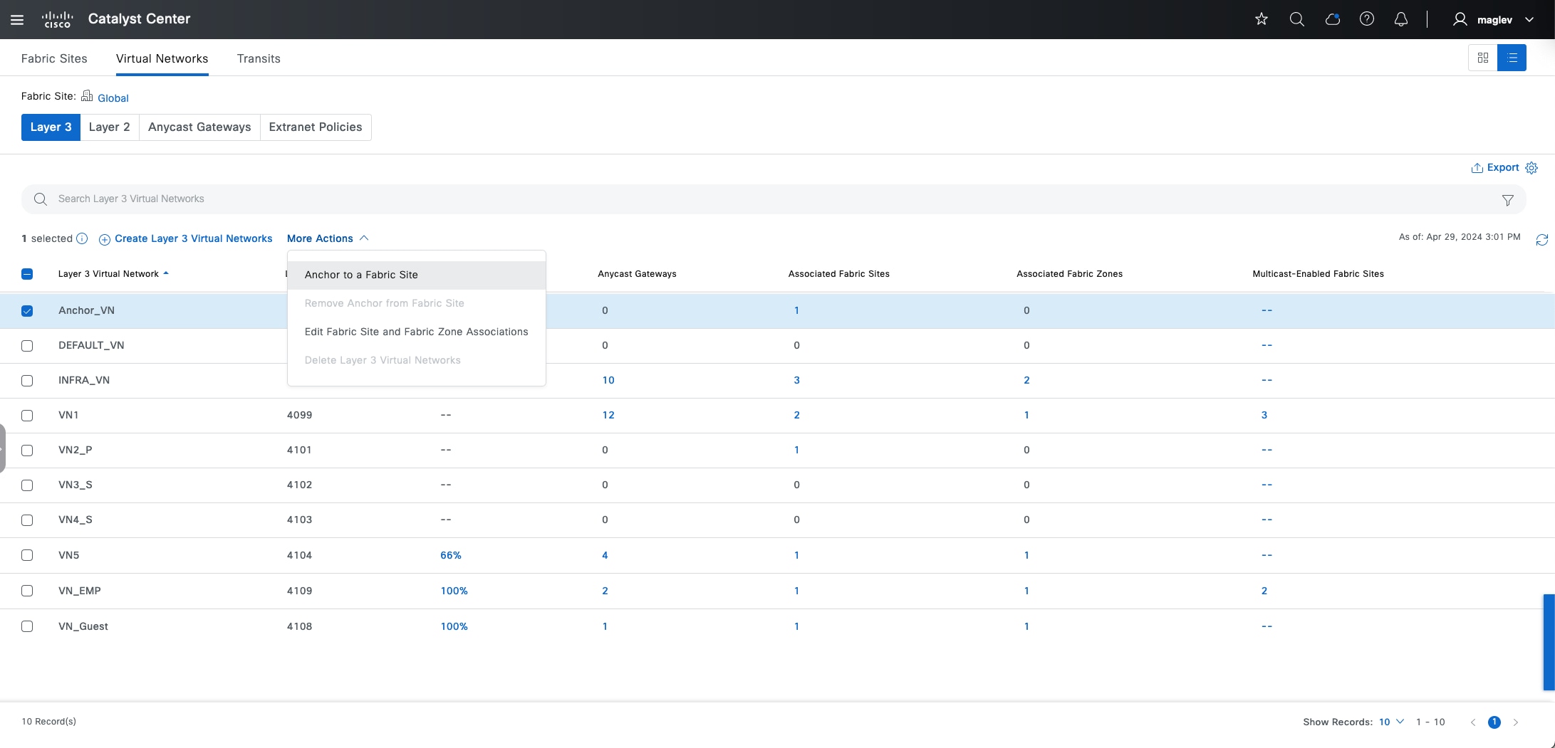
Step 5. After the task finishes, Anchor_VN has a new anchor icon. Click the icon to view the anchor site information.
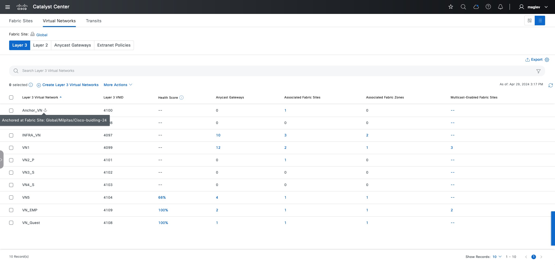
Step 6. Create an anycast gateway and add an IP pool for the anchor VN.
After a VN is configured as an anchor VN, all the associated IP pools are also anchored and can be selected and used by anchoring sites.
See the Create anycast gateway section and create new anycast gateways in Anchor_VN.
● From the top-left corner, click the menu icon and choose Design > Network Settings, click the IP Address Pools tab, then reserve the IP pool for Building-24-Anchor (see Procedure 2: Reserve IP pools for a fabric site.)
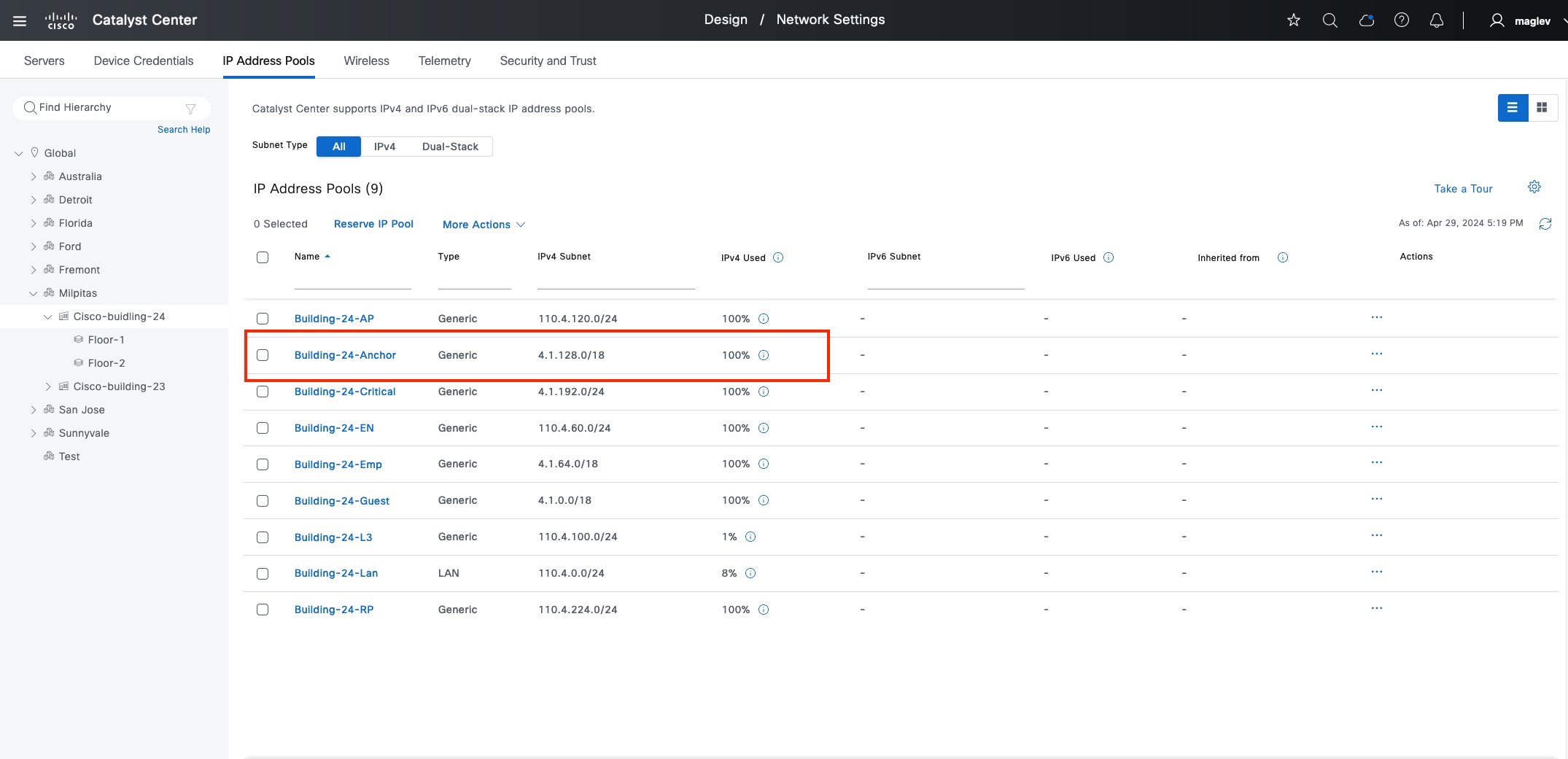
● Create an anycast gateway and add it to Anchor_VN in Cisco-building-24.
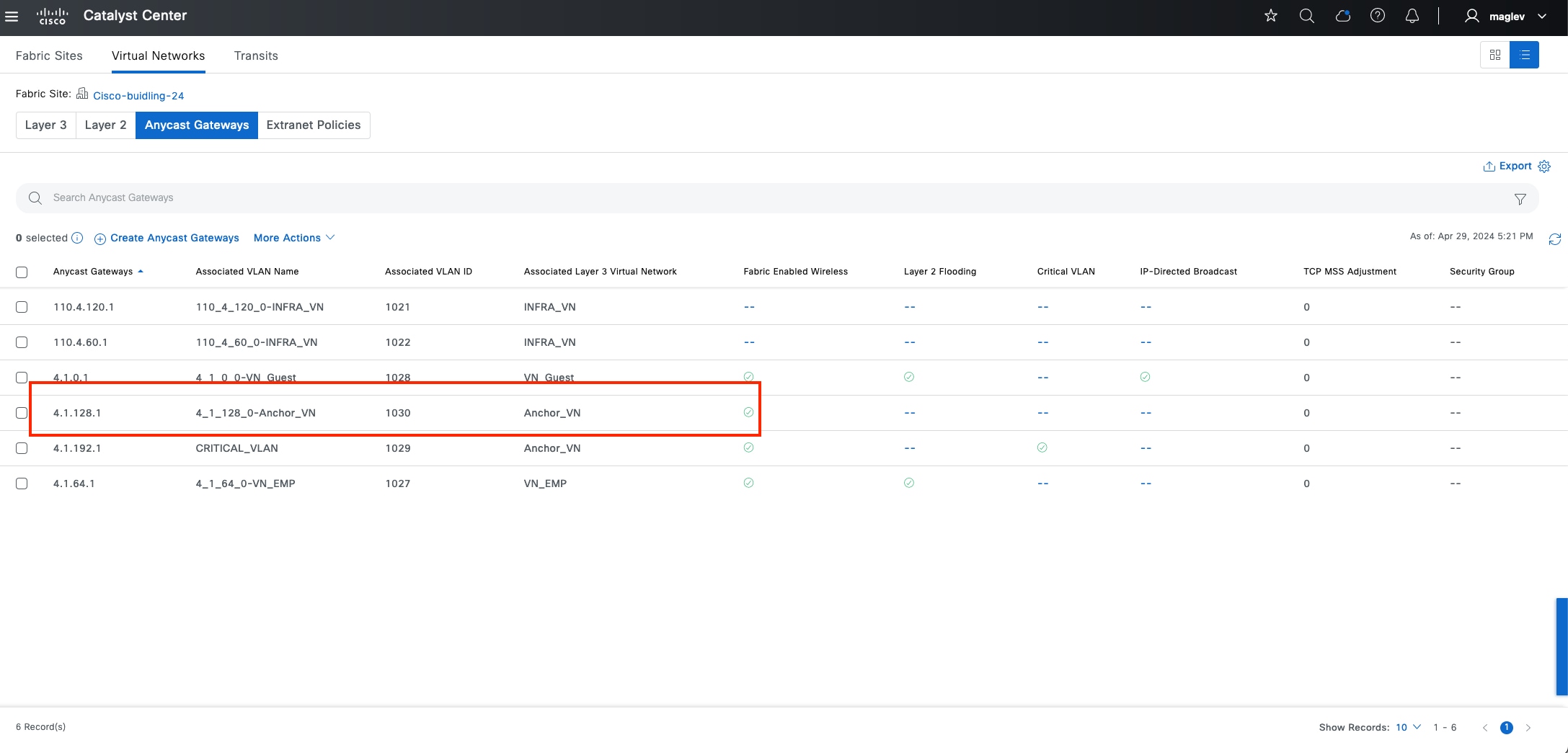
Procedure 2. Add anchor VN and anchor pool to anchored sites
Navigate to other fabric sites, in this example another fabric site Cisco-building-9 is used to demonstrate the process. Cisco-building-9 has two local control plane nodes (IP:2.3.3.11 and 2.3.3.12), several edge nodes and one standalone C9800 wireless controller.
Step 1. From the top-left corner, click the menu icon and choose Provision > Fabric Sites, click the table view icon in the top right, click the Cisco-building-9 text link, then click the Layer 3 Virtual Networks tab.
Step 2. Click Add Existing Layer 3 Virtual Networks, in the slide-in pane, check Anchor_VN then click Add to complete the workflow and deploy the task.
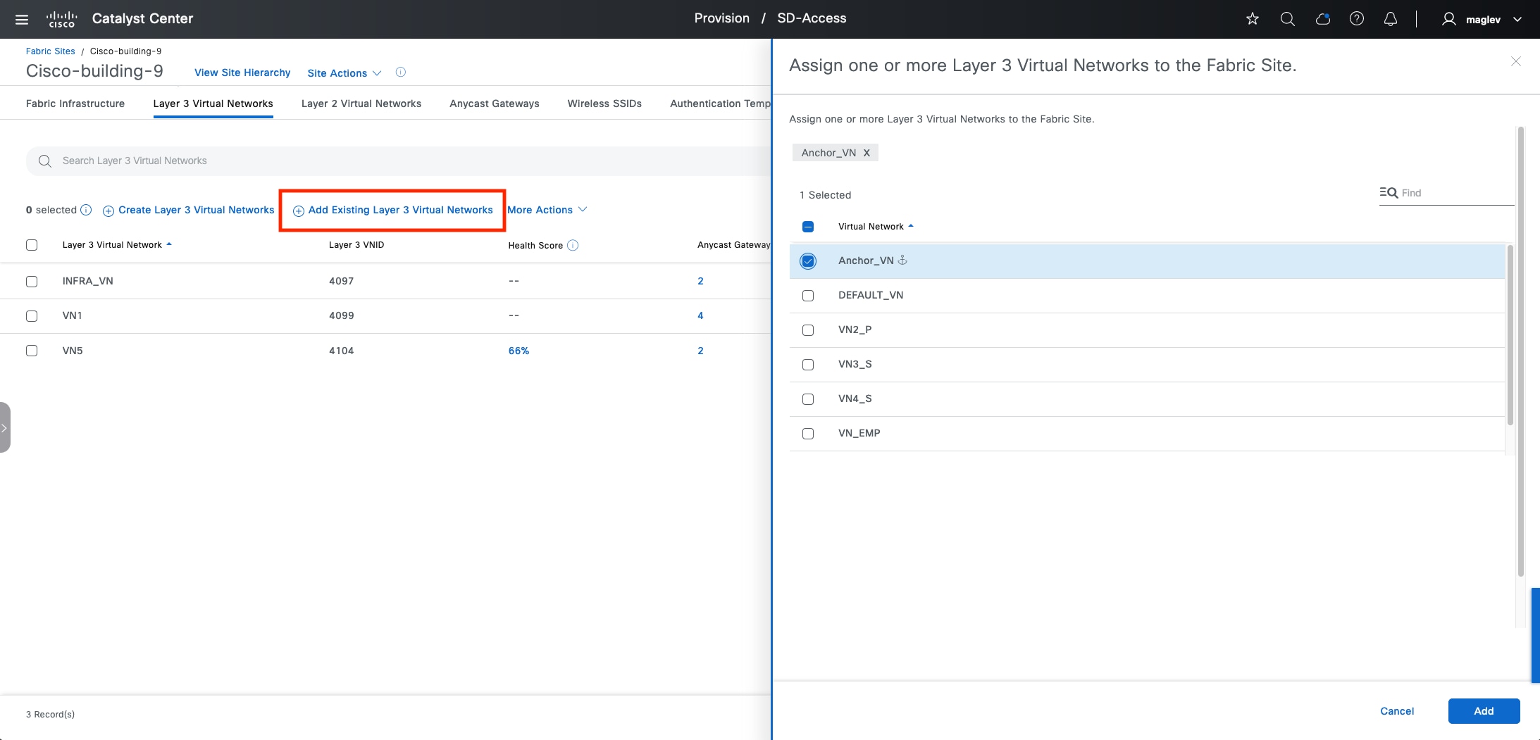 After the task is done, Anchor_VN is added with the anchor icon identifying Cisco-building-24 as the anchor site.
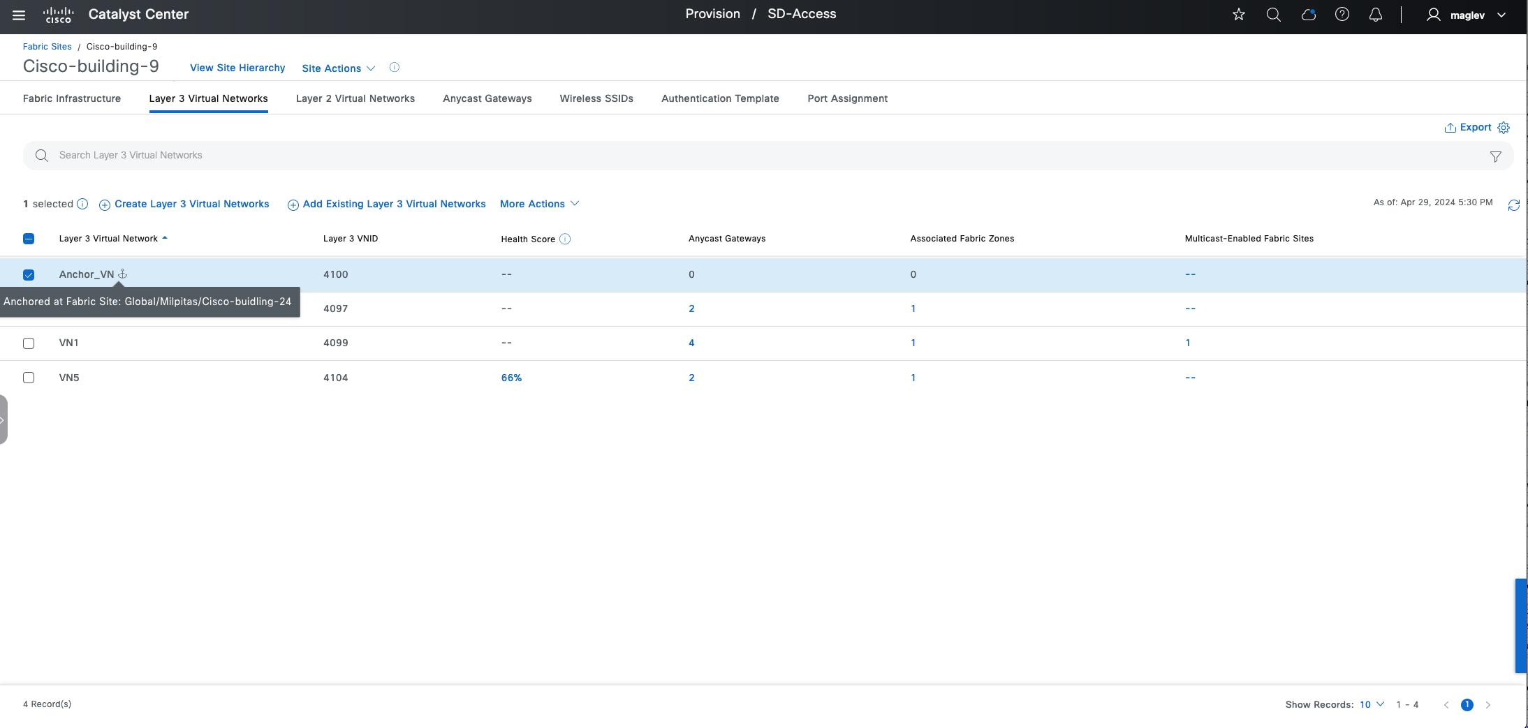
Step 3. Add an IP address pool. Navigate to the Anycast Gateways tab then click Create Anycast Gateways.
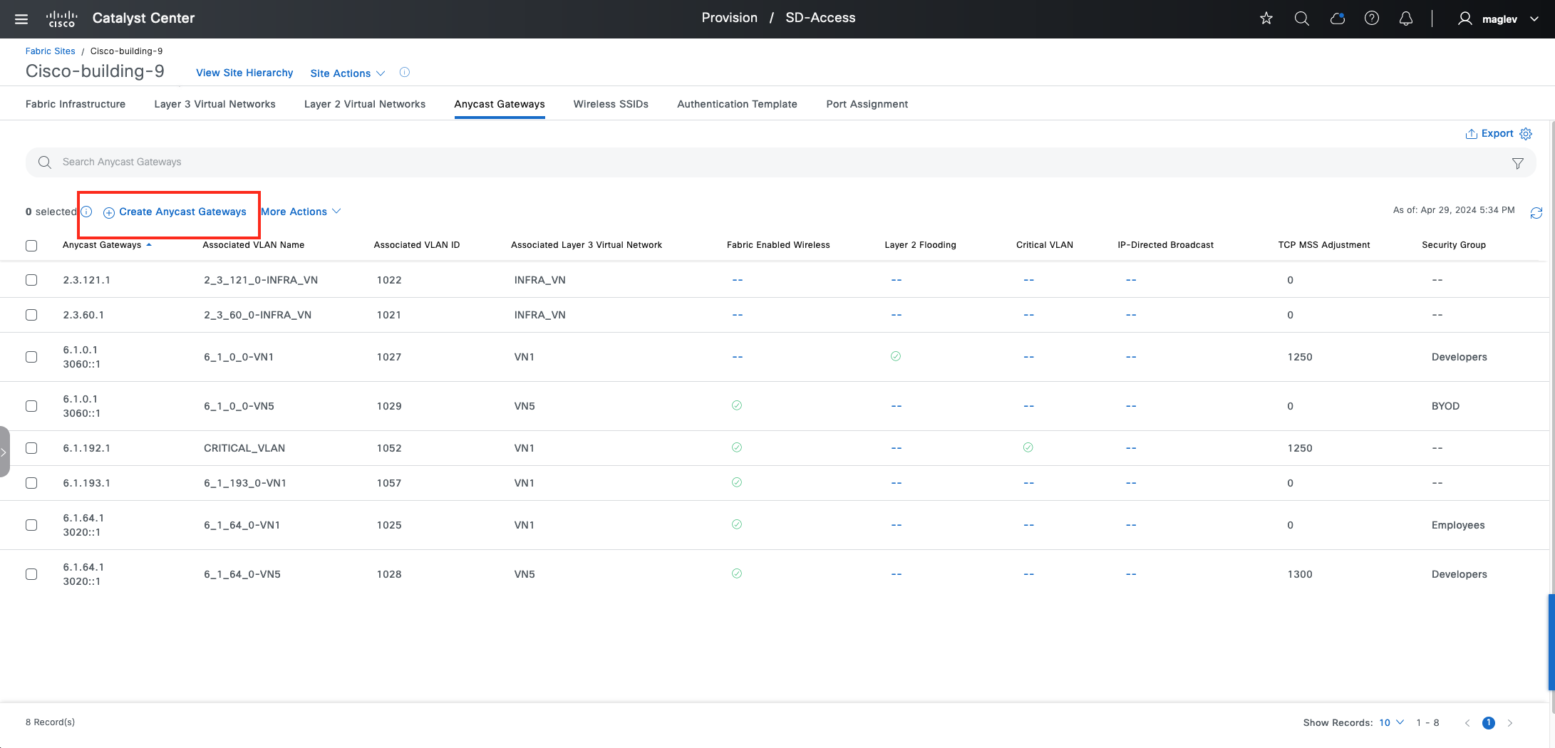
Step 4. Choose Anchor_VN.
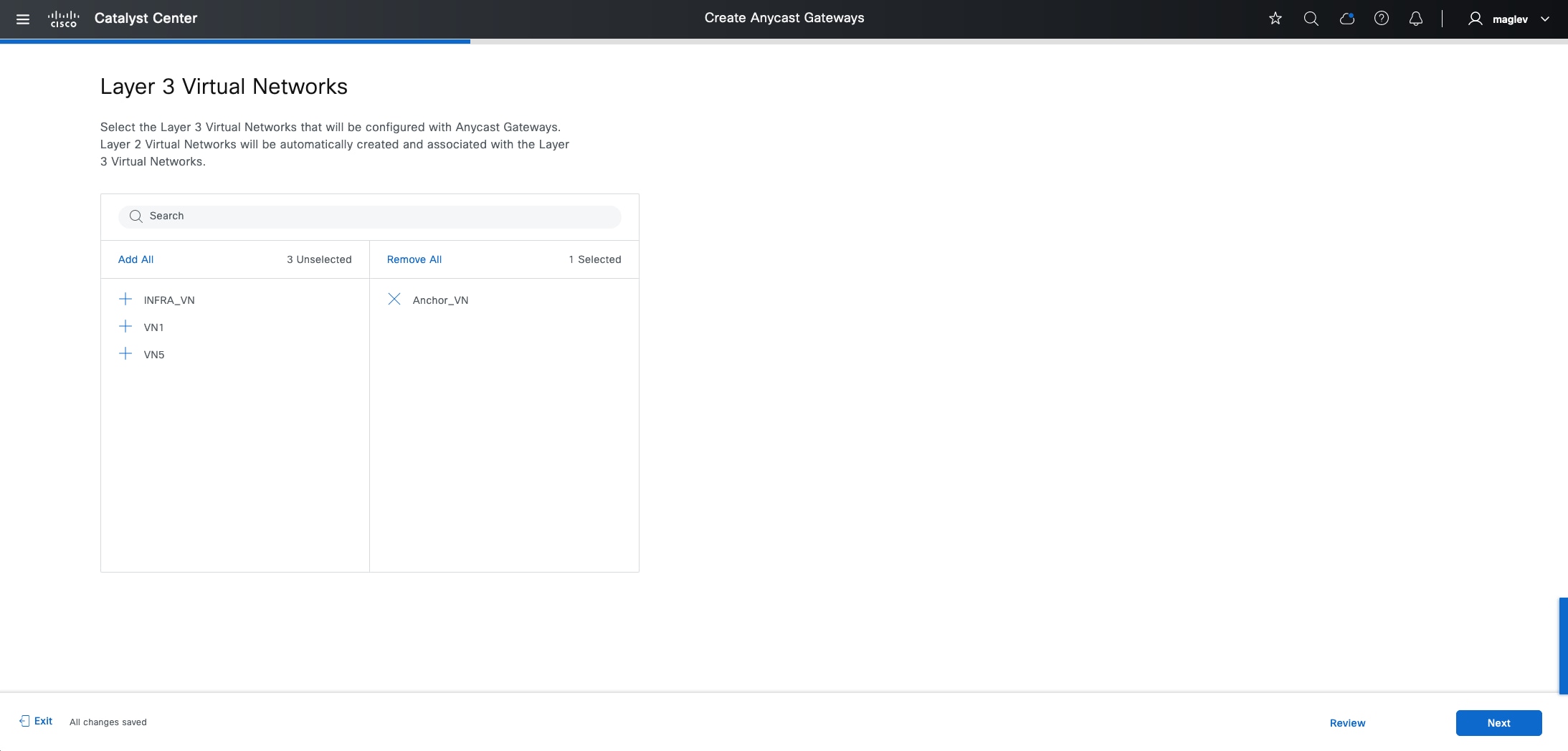
Only anchor pools are available to be added in Anchor_VN.
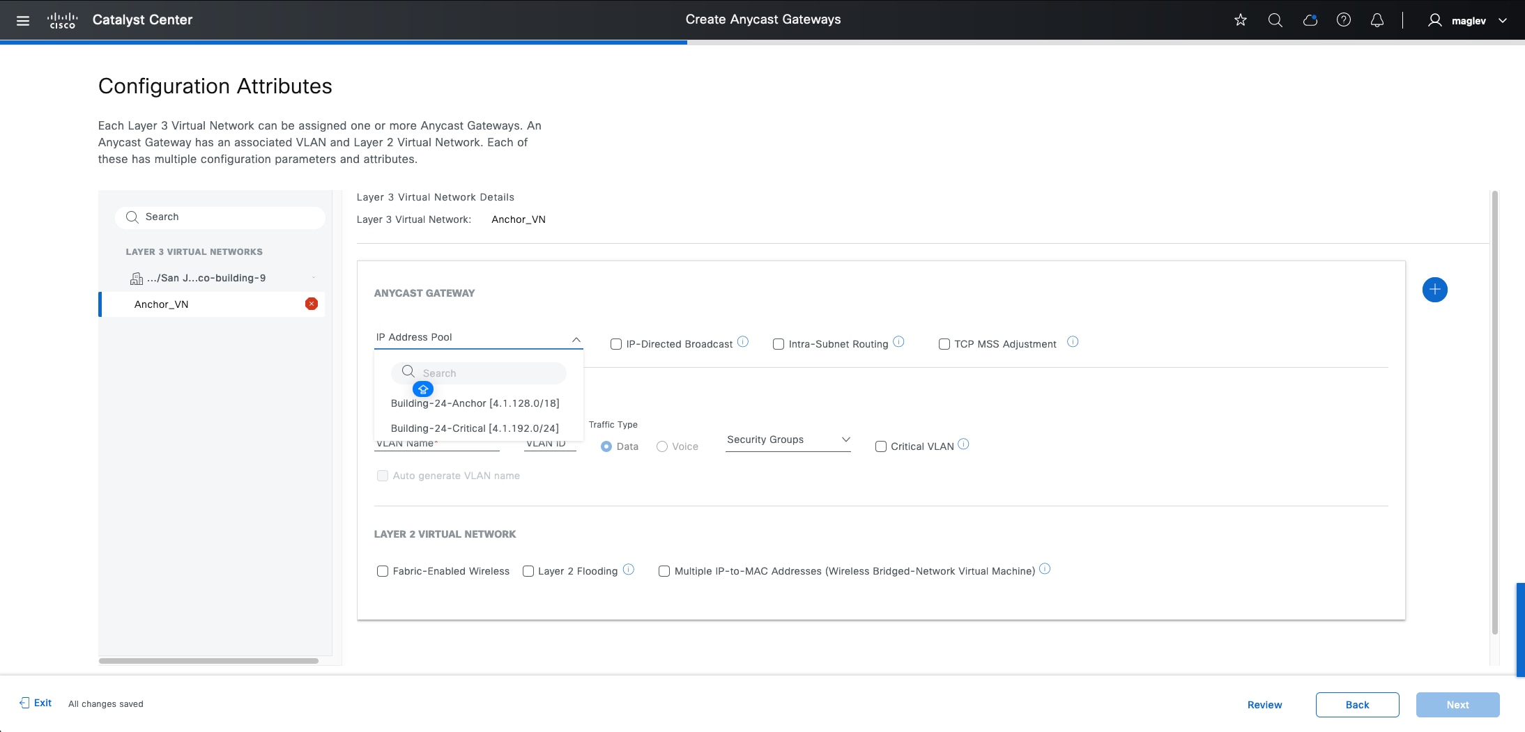
Step 5. Add the Building-24-Anchor pool with preferred attributes and complete the workflow.
Step 6. On the fabric edge node for Cisco-building-9, review the four established LISP sessions. The first two are established with the Cisco-building-9 local control plane, and the last two are established with the Cisco-building-24 anchored control planes.
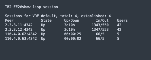
Tech tip: Ensure edges in the inherited site have an explicit route to the loopback0 interface address of control plane nodes and border nodes on an anchor site in the global routing table. Control plane nodes and border nodes on an anchor site also have an explicit route to loopback0 interface address edges.
Step 7. Associate the anchor pool with SSID in the inherited site.
The anchor pool can be used for both wired and wireless clients in the inherited site.
Step 8. To use the anchor pool for wireless client, check the Fabric-Enabled Wireless check box for the anchor pool Configuration Attributes.
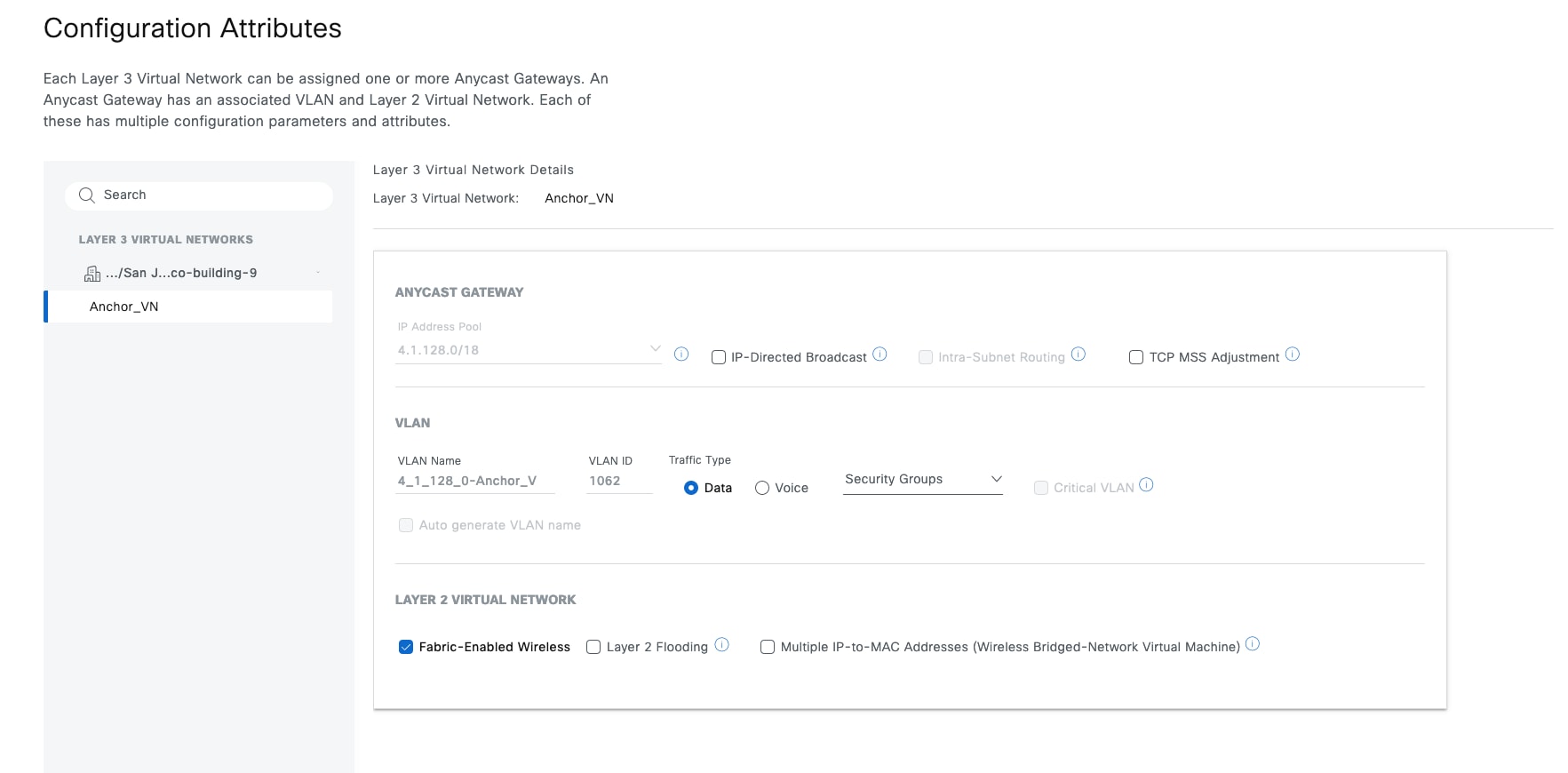
Step 9. From the menu icon button, choose Provision > Fabric Sites, click the table view icon in the top right, click the Cisco-building-9 text link, click the Wireless SSIDs tab then associate the anchor pool to SSID ASR-Guest and deploy the task.
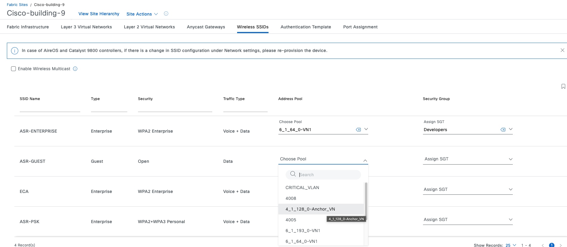
Step 10. Use the command show wireless fabric summary to validate on the wireless controller in Cisco-building-9. The standalone wireless controller uses these control plane nodes:
◦ default-control-plane is a local control plane and used by all the local segments (layer 2 and layer 3) that have the Fabric-Enabled Wireless attribute enabled.
◦ Milpitas_Cisco-bu_e087e is the control plane node in the anchor site Cisco-Building-24. The anchor pool segment is also associated with it.
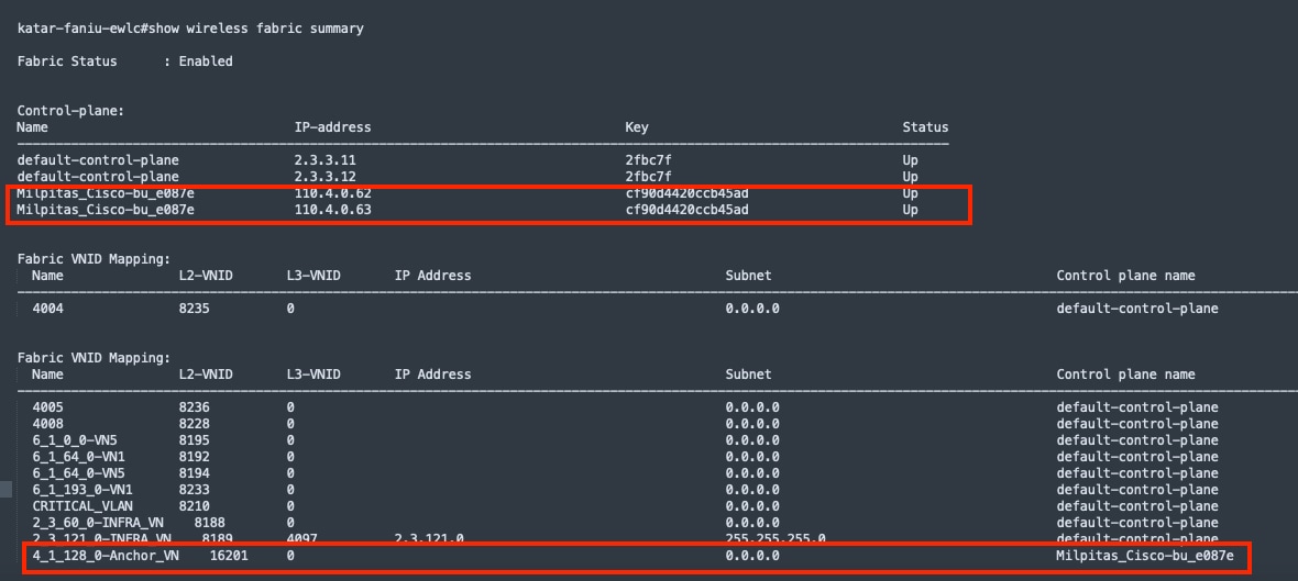
Step 11. Use the command show fabric wlan summary to validate the status of the WLAN named ASR-Guest.
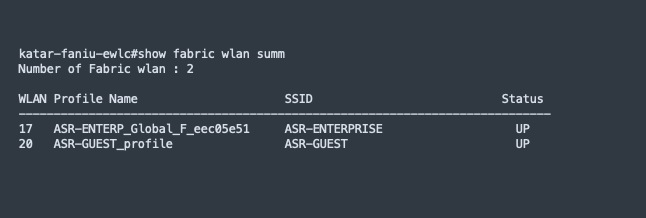
Create anycast gateway for critical VLAN
By default, when a network access device (NAD) cannot reach its configured RADIUS servers, new hosts connected to the NAD cannot be authenticated and are not provided access to the network. The inaccessible authentication bypass feature, also referred to as critical authentication, AAA fail policy, or simply critical VLAN, allows network access on a particular VLAN when the RADIUS server is not available (down).
When a NAD tries to authenticate an endpoint connected to a port, it first checks the status of the configured RADIUS servers. If a server is available, the NAD can authenticate the host. If all the configured RADIUS servers are unavailable and the critical VLAN feature is enabled, the NAD grants network access to the endpoint and puts the port in the critical-authentication state which is a special-case authentication state. When the RADIUS servers are available again, clients in the critical-authentication state must reauthenticate to the network.
Similarly, critical voice VLAN support works by putting voice traffic into the configured voice VLAN if the RADIUS server becomes unreachable.
Cisco SD-Access uses VLAN name CRITICAL_VLAN for critical data VLAN, and VIOCE_VLAN with VLAN id 2046 for the critical voice VLAN and cannot be changed. A fabric site can only have one critical data VLAN and one critical voice VLAN. Critical Voice VLAN 2046 is also Voice VLAN deployed in all fabric edges by default. So, the critical voice VLAN does not need to be explicitly defined, as the same VLAN is used for both voice and critical voice VLAN support. This ensures that phones will have network access whether the RADIUS server is available or not.
In Cisco SD-Access dot1x multidomain case where IP phone is connected to FE and another endpoint such as a laptop is connected to IP phone, when Radius server is down, IP phone can be granted with limited access through critical voice VLAN and the laptop can be granted with limited access through critical data VLAN.
Step 1. In the Network Setting window, reserve two new IP Address Pools for Cisco-building-24.
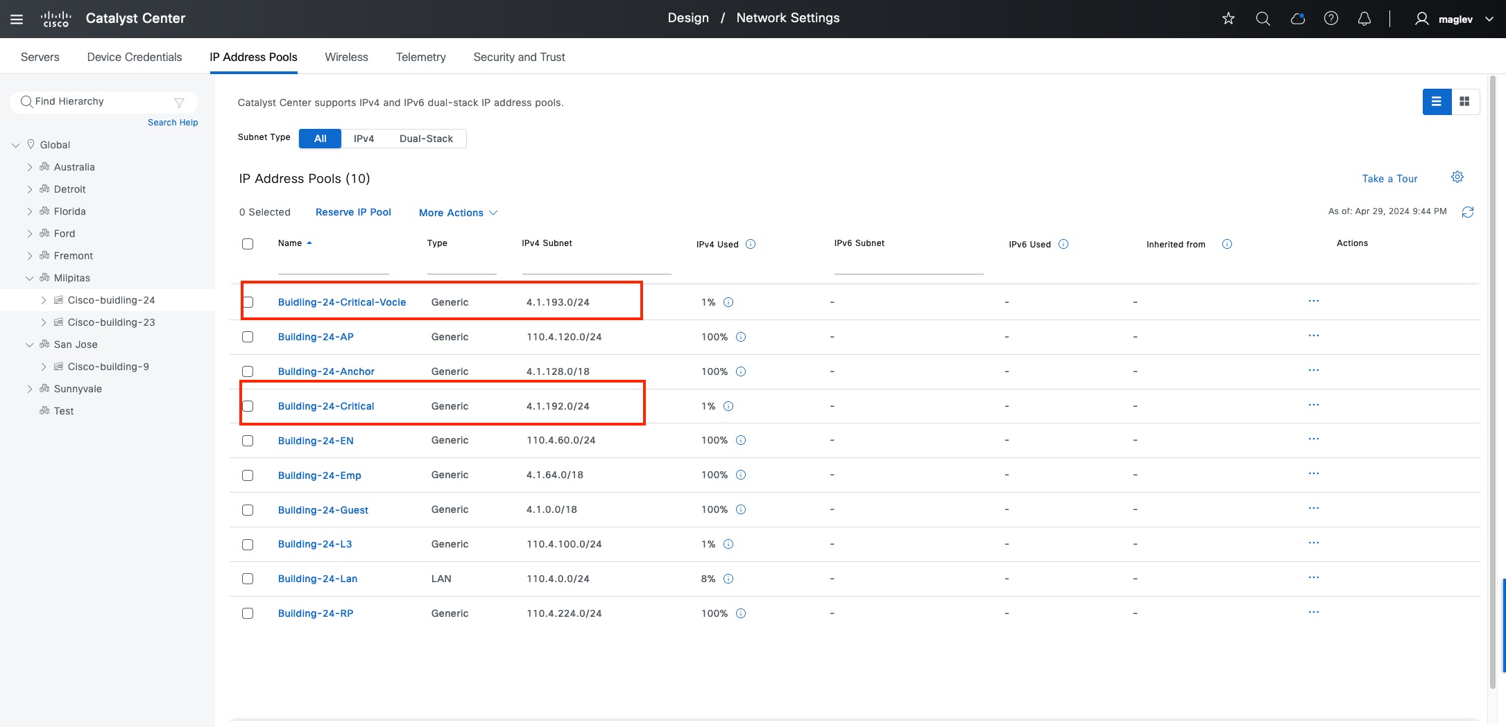
Step 2. From the menu icon button, choose Provision > Virtual Networks, click the table view icon in the top right.
Step 3. Click the Anycast Gateways tab then click Create Anycast Gateways and select Anchor_VN.
Step 4. Add two pools with Critical VLAN check boxes checked.
◦ Critical VLAN for voice traffic. VLAN Name and VLAN ID cannot be customized.
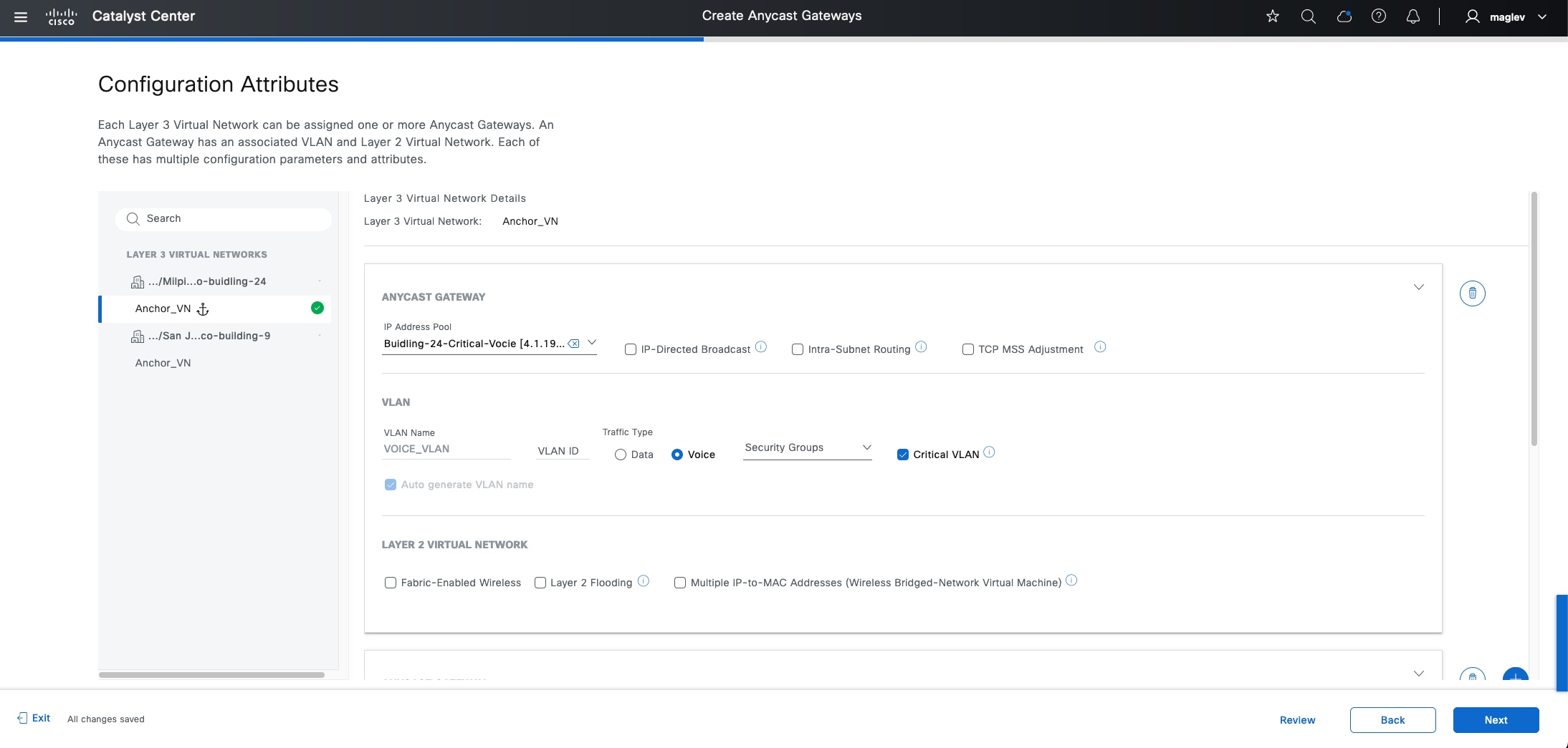
◦ Critical VLAN for data traffic. VLAN Name cannot be customized. VLAN ID can be edited.
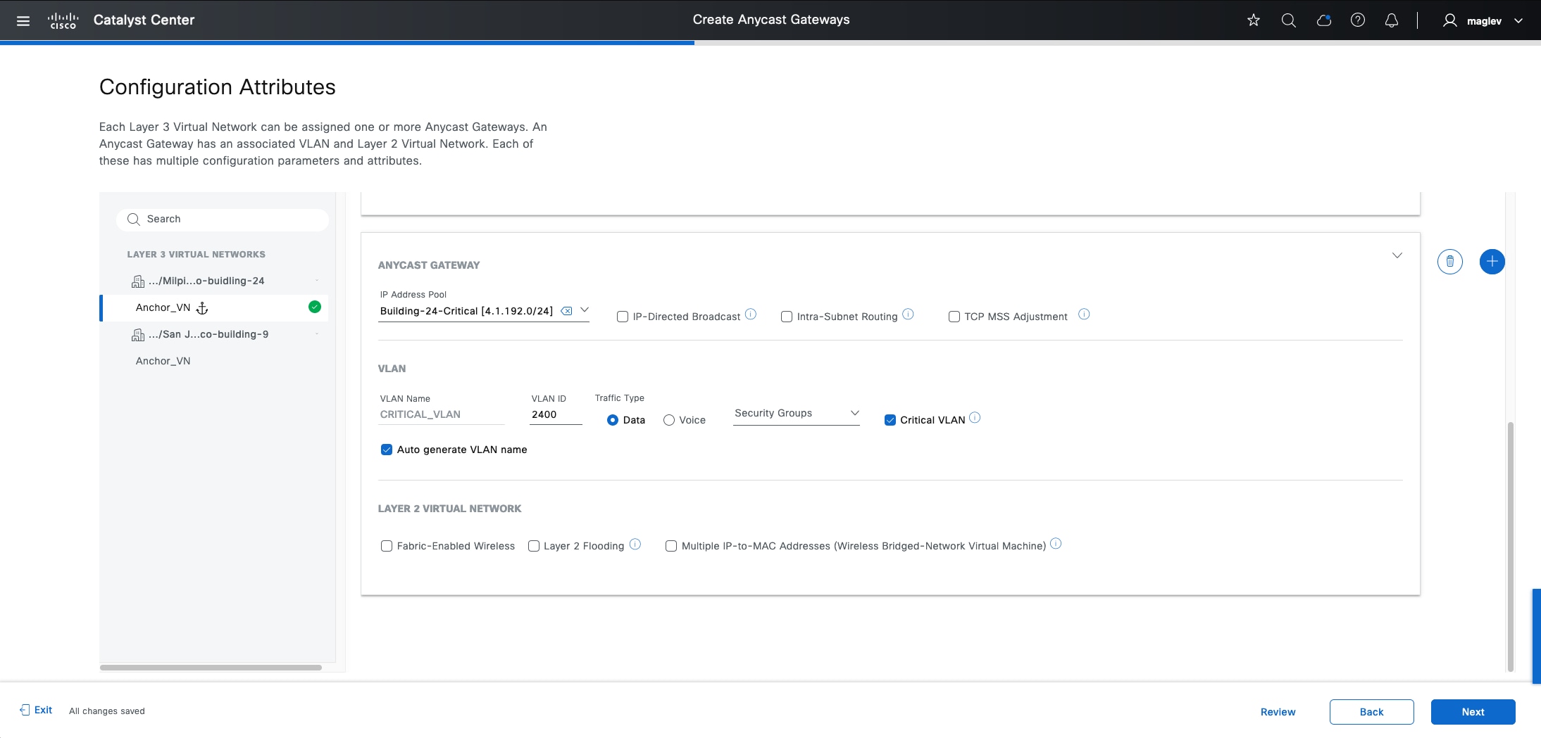
Step 5. Click Next to complete the workflow and deploy the task.
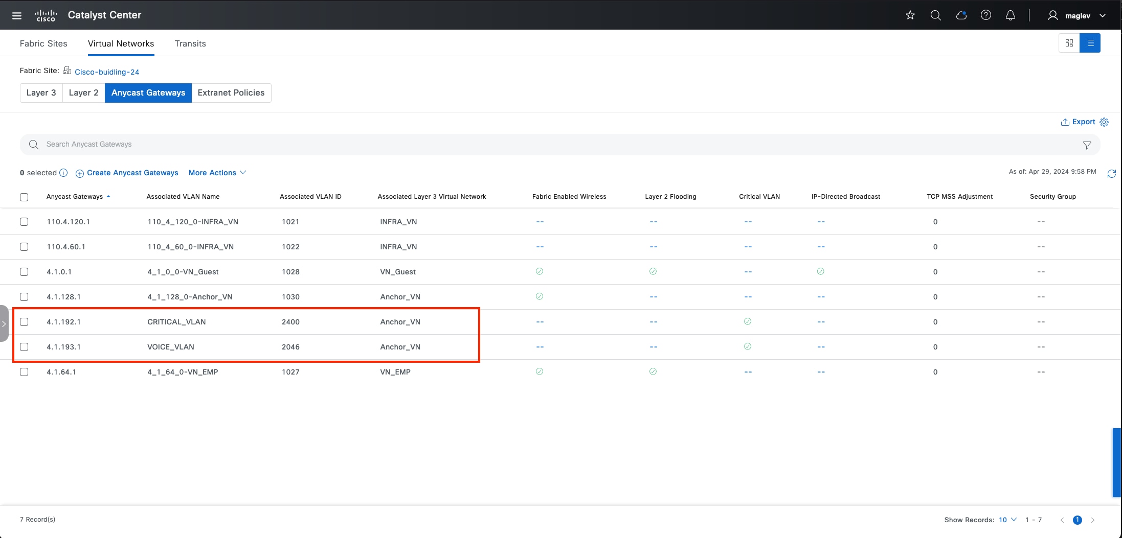
(Optional) Provision C9800 wireless controller
This process is focused on adding a C9800 device as a fabric enabled wireless controller.
As discussed in the previous section, a standalone physical C9800 wireless controller has a higher scale number and better Assurance support by Catalyst Center. It can be added as a fabric enabled wireless controller or an OTT wireless controller in a Cisco SD-Access deployment.
Generic steps to deploy a C9800 wireless controller include:
1. Create a wireless network profile with SSID (see Configure a Wireless SSID).
2. Discover and provision a C9800 device.
3. Add the C9800 device to the fabric (fabric enabled wireless controller).
The procedures in this section demonstrate provisioning a C9800 wireless controller to the Cisco-Building-9 fabric site to manage Floor-1. This fabric site already has a wireless controller that manages Floor-2. The network profile with SSID was added already.
Procedure 1. Discover the C9800 device
Step 1. From the top-left corner, click the menu icon, choose Tools > Discovery then click Add Discovery in the top right.
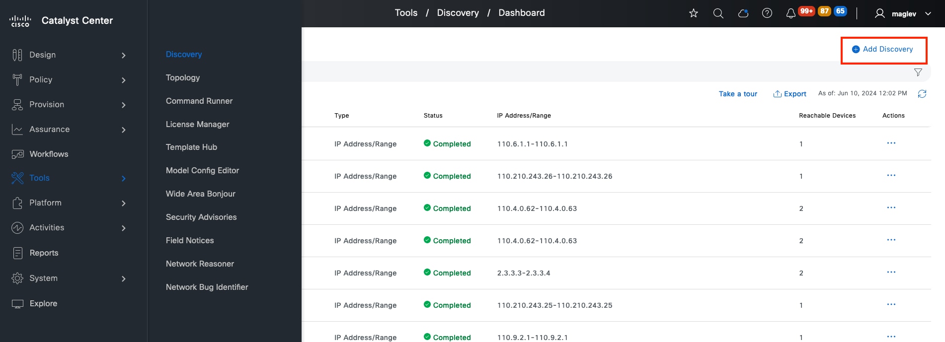
Step 2. Enter the IP information.
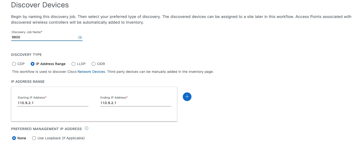
Tech tip: Wireless management IP needs to be configured in C9800 device and cannot use DHCP assigned IP address.
Step 3. Enter the mandatory required information for CLI, SNMP, and Netconf then start the discovery task.
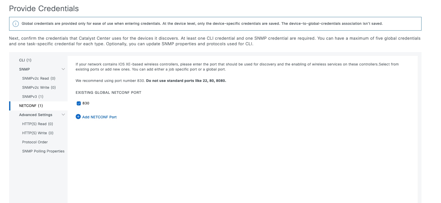
When the discovery is successful, the Discovery window opens.
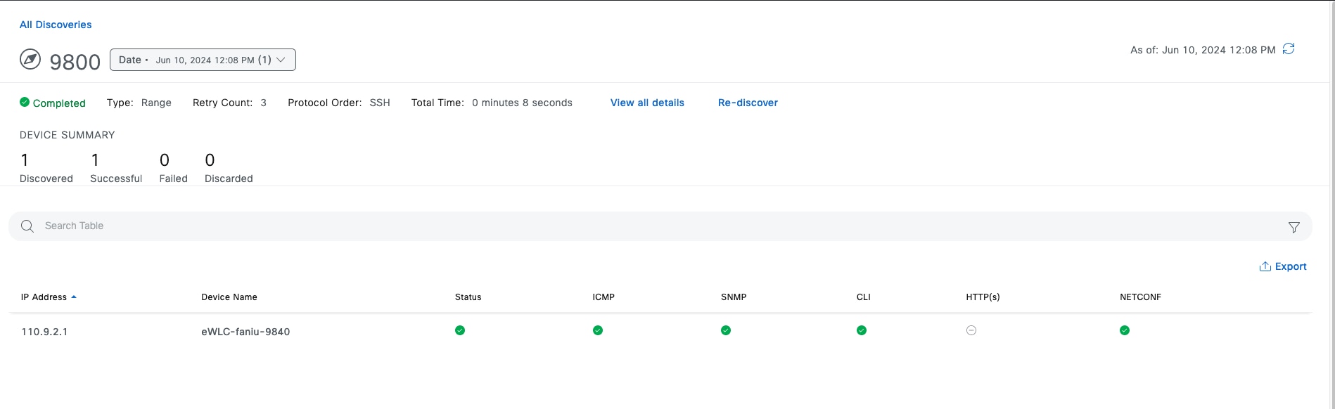
Step 4. Validate in the Inventory window. From the top-left corner, click the menu icon and click Provision > Inventory, ensure the device is in Managed status.
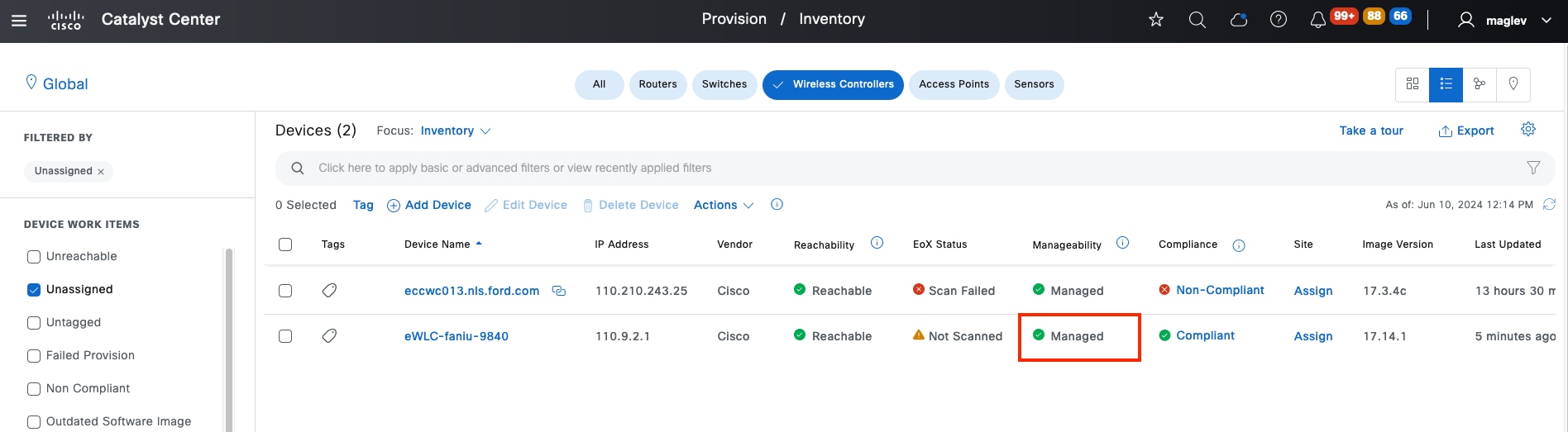
Tech tip:
1. A filter can be applied to locate the device faster. In the above example, click Wireless Controllers on top, click Device Work Items > Unassigned in the left pane.
2. Unassigned means the device is not assigned to a site yet. If discovered devices are already assigned to the site during the Discovery workflow. In the top left, click Global to switch to the site.
Procedure 2. Assign and provision C9800 to the site
Step 1. Check the device check box then choose Actions > Provision > Assign Device to Site.
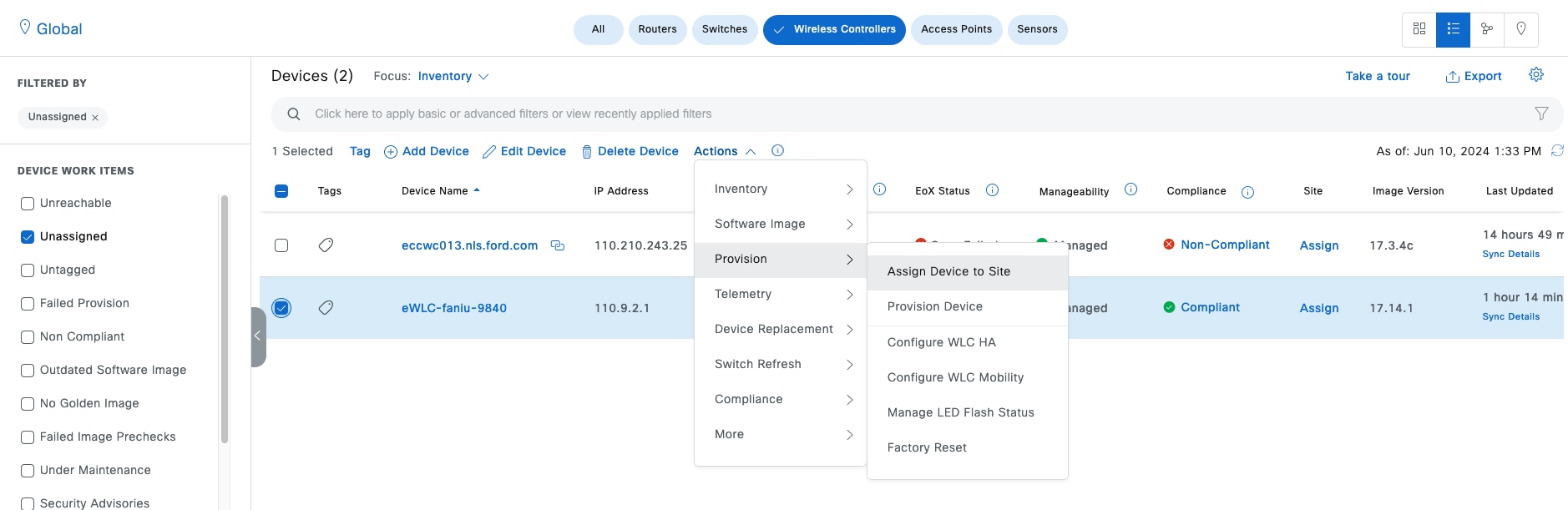
Step 2. Click Choose a site.
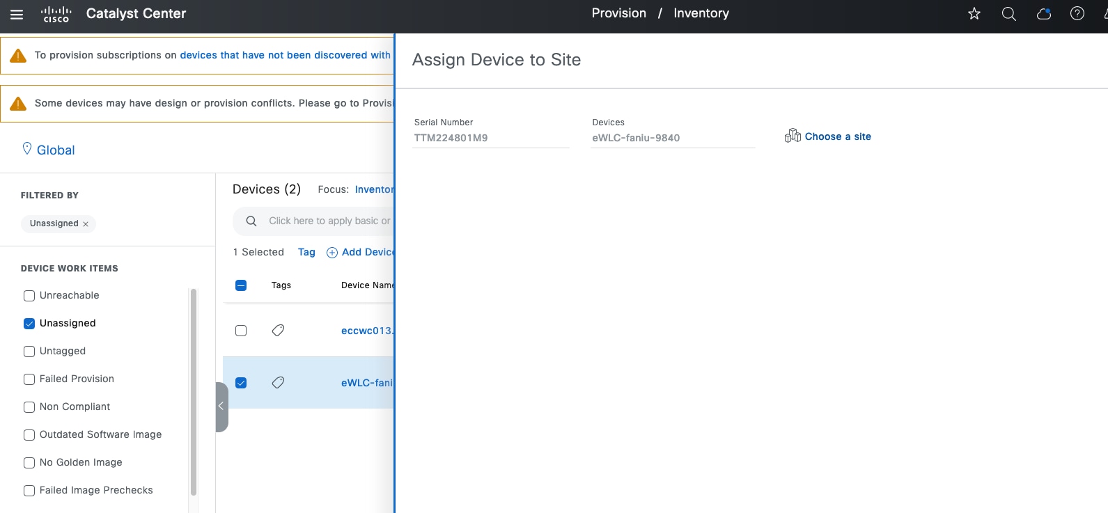
Step 3. Choose the site Cisco-building-9 then click Save to complete the workflow and deploy the task.
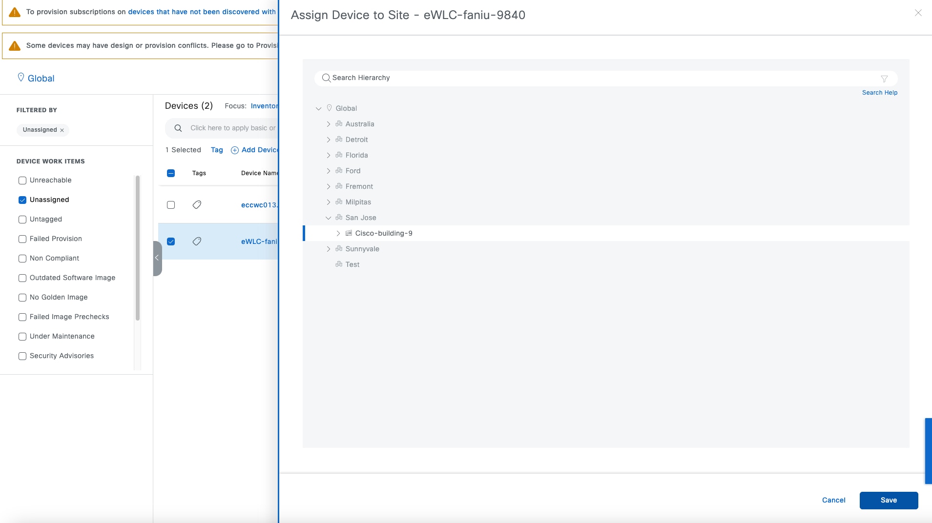
Step 4. After site assignment, the previous filter is not applicable. Change the location from Global to Cisco-building-9 and uncheck the Unassigned check box to see the device then choose Actions > Provision > Provision Device.
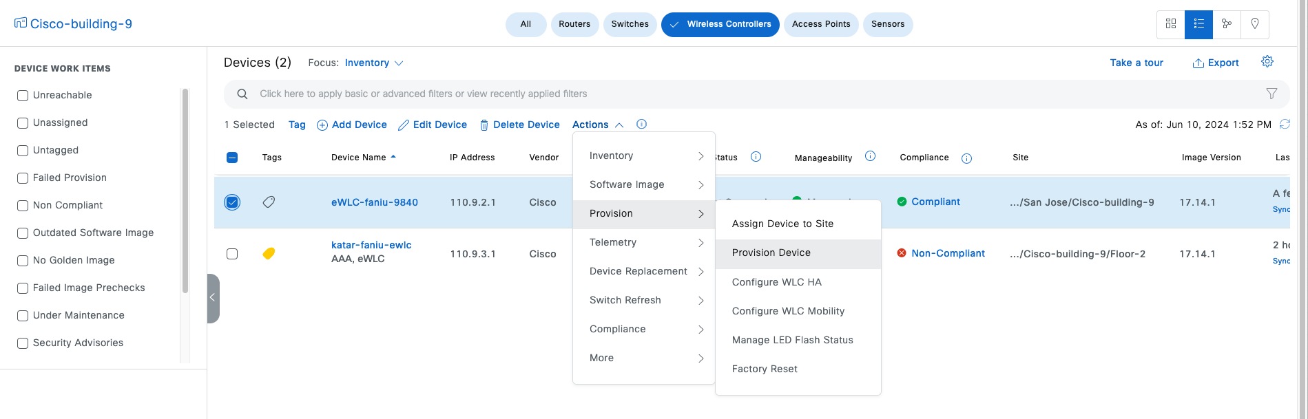
Step 5. Choose the Primary managed location for the AP named Floor-1.
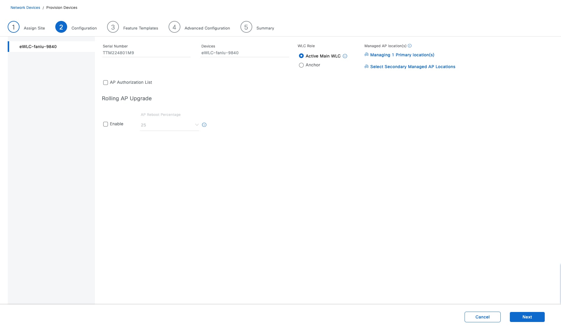
Step 6. Choose and confirm the Advance SSID configurations (optional).
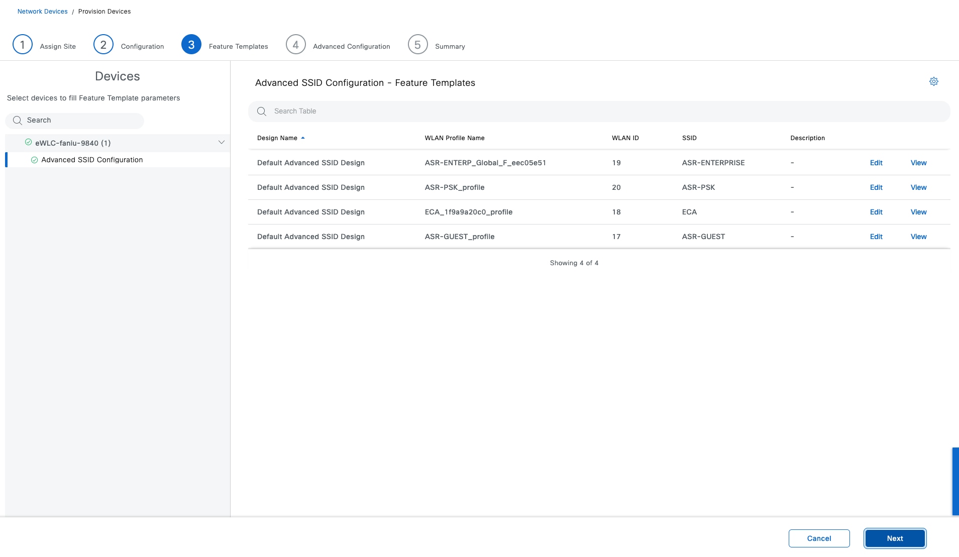
Step 7. Click Next to Advanced Configuration (optional), the CLI template shows if there is any template associated.
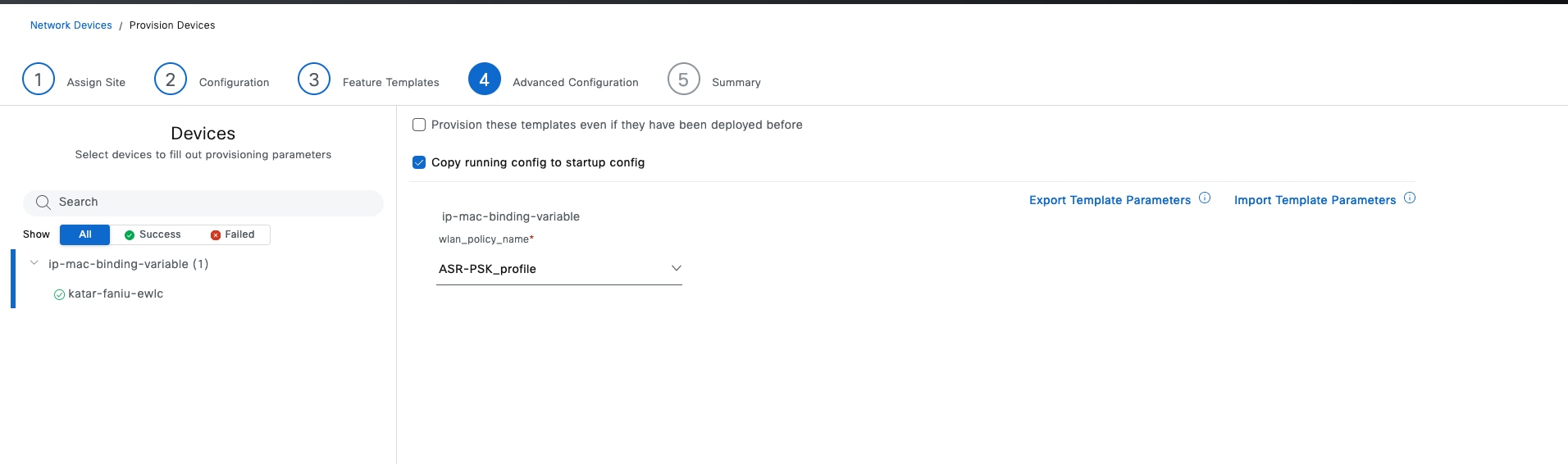
Step 8. Click Next to review the configuration in Summary window and deploy the task.
Procedure 3. Add the C9800 device to the fabric site as a fabric enabled wireless controller
Step 1. From the top-left corner, click the menu icon and choose Provision > Fabric Site, click the table view icon in the top right, then click the Cisco-building-9 text link.
Step 2. Locate the wireless controller, enable Wireless LAN Controller then click Add to deploy the task.
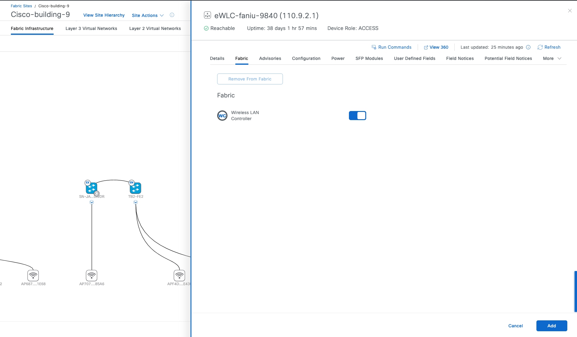
Tech tip: To make the fabric control plane protocol more resilient, there must be a specific route to the wireless controller in the global routing table for each fabric node. The route to the wireless controller IP address should be either redistributed into the underlay Interior Gateway Protocol (IGP) at the border or configured statically at each node. The wireless controller is an RLOC within the Cisco SD-Access. For the LISP RLOC reachability check, a specific route to the wireless controller is required on the underlay. The wireless controller should not be reachable through the default route.
Procedure 4. Configure fabric wireless SSID
Step 1. From the top-left corner, click the menu icon and choose Provision > Fabric Site, click the table view icon in the top right, click the Cisco-building-9 text link, click the Wireless SSID tab and associate the IP Address Pool as shown in this figure:
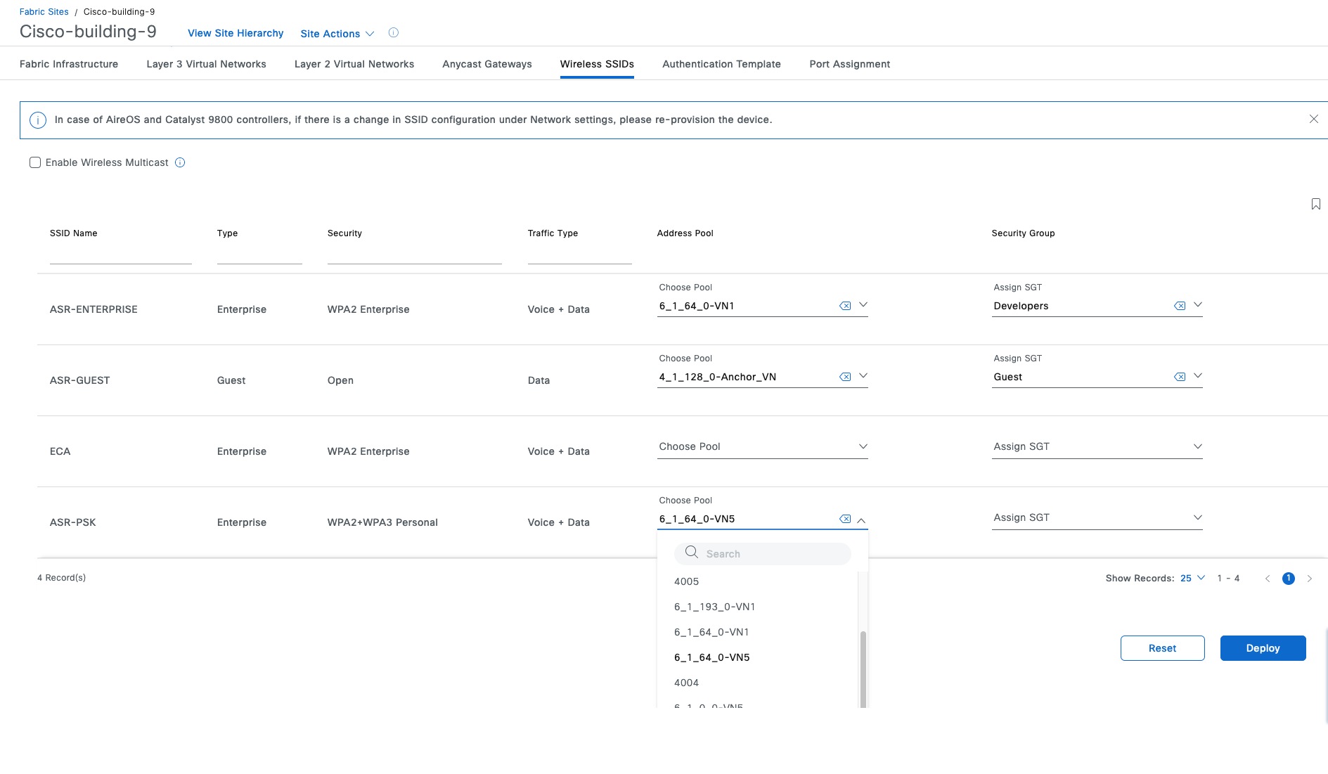
Note: The Fabric SSID is up after the layer 3 IP pool or the layer 2 segment is associated.
Step 2. Check the Enable Wireless Multicast check box to enable Global Multicast mode and Internet Group Management Protocol (IGMP) snooping on the wireless controller (site-level overlay multicast configuration is required).
Step 3. Check the Enable Wireless Multicast check box.
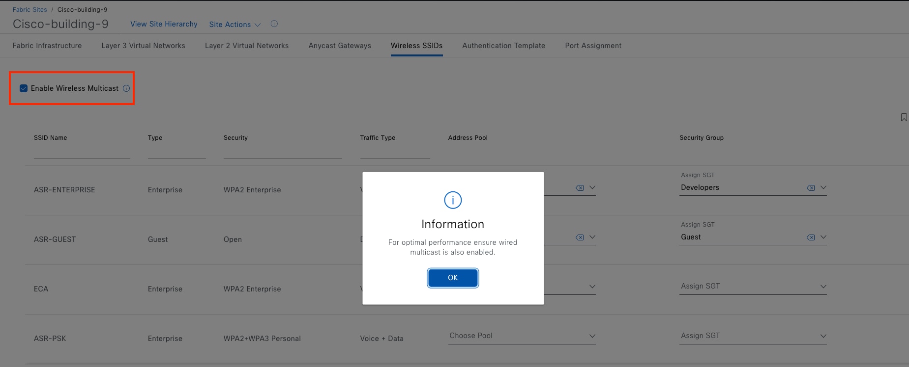
This section explains the procedures of day-n operations for endpoints onboarding, making changes to fabric sites, replacing a faulty fabric device, and tearing down using Catalyst Center.
Onboard APs
APs are a special case in the fabric. They are connected to edge nodes like an endpoint, although they are part of the fabric infrastructure. Because of this, their traffic pattern is unique. APs receive a DHCP address using the overlay network and associate with the wireless controller using the underlay network. When associated with the wireless controller, they are registered with Catalyst Center by the wireless controller through the overlay network. To accommodate this traffic flow, the AP subnet, which is in the Global Routing Table (GRT), is associated with the overlay network.
In Procedure 1: Add an anycast gateway in INFRA_VN, the anycast gateway for APs has been configured.
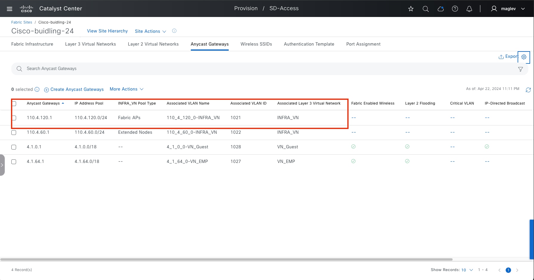
Note: Ensure the reachability between Catalyst Center and the AP, between wireless controller and the AP.
Procedure 1. Assign AP ports
This procedure onboards the AP in Cisco-building-24 and joins the embedded wireless controller N+1 peer Common-A and Common-B.
Catalyst Center enables automatic onboarding of APs. Autoconf is used to identify the device as a Cisco AP and the connected edge port gets the correct configuration when the authentication template is set to No Authentication. If a different authentication template is used globally, for example Closed Authentication, then unless secure AP onboarding is required, the switchport configurations on the edge nodes must be changed.
Step 1. From the top-left corner, click the menu icon and choose Provision > Fabric Site, click the table view icon in the top right, then click the Cisco-building-24 text link, click the Port Assignment tab.
Step 2. Locate and check the check box for the fabric edge Switch-110-4-8 with the Interface Name port GigabitEthernet1/0/3, in the slide-in pane select Access Point and Authentication Template type None then click Update.
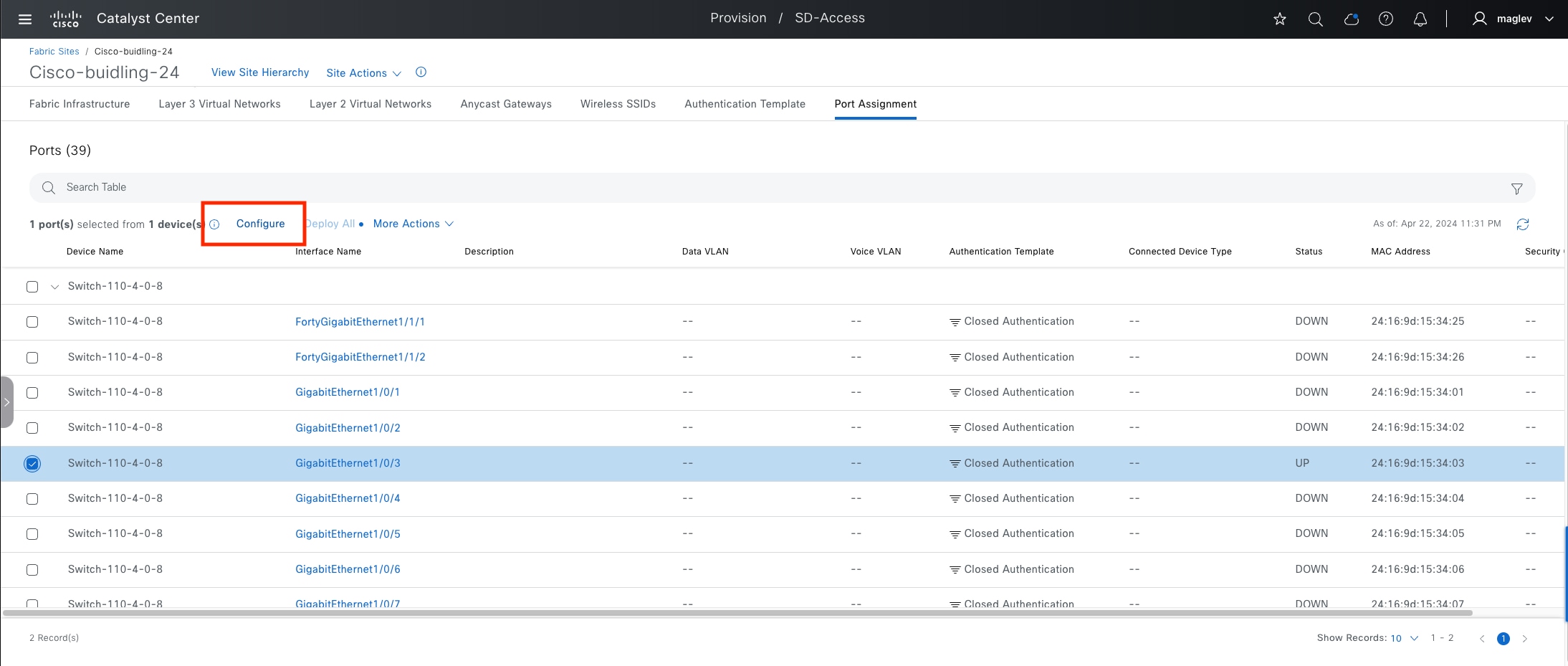
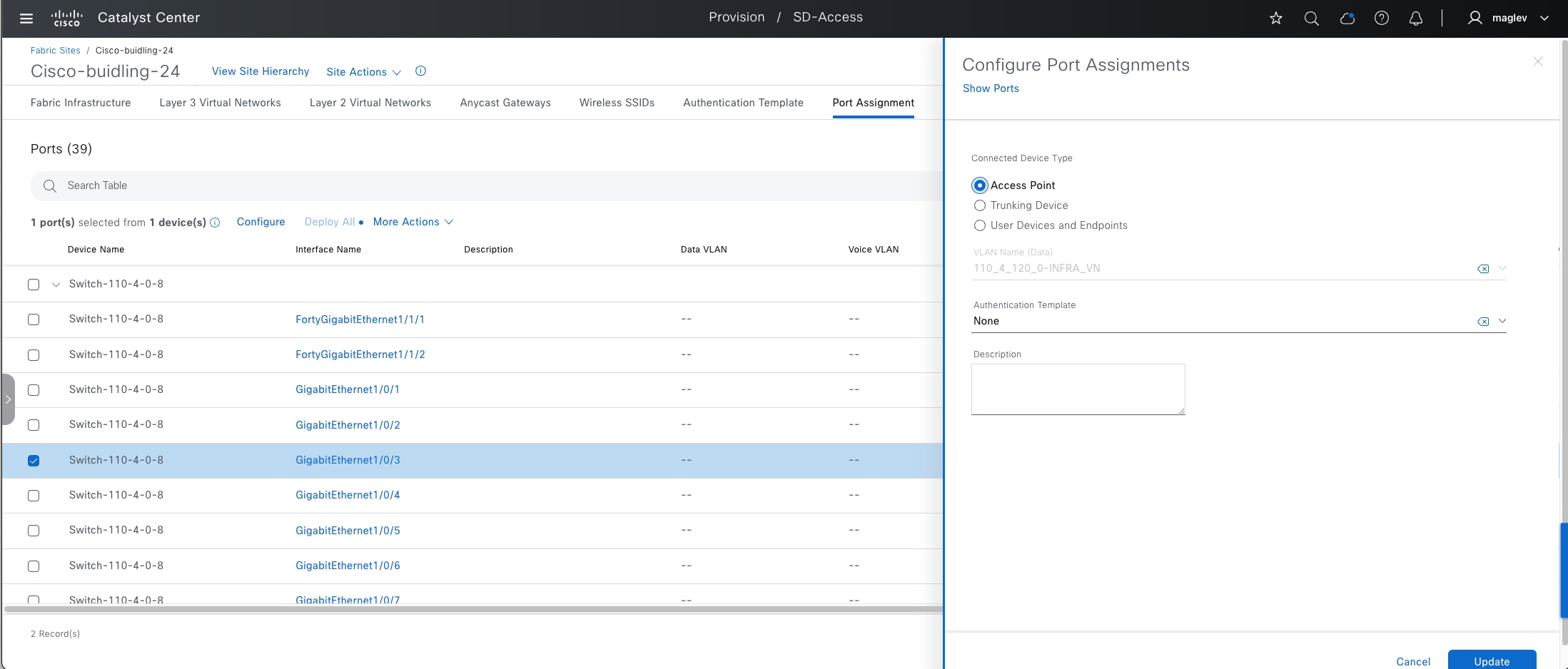
Step 3. (Optional) Configure more ports.
Step 4. Click Deploy All to push the configuration to the ports.
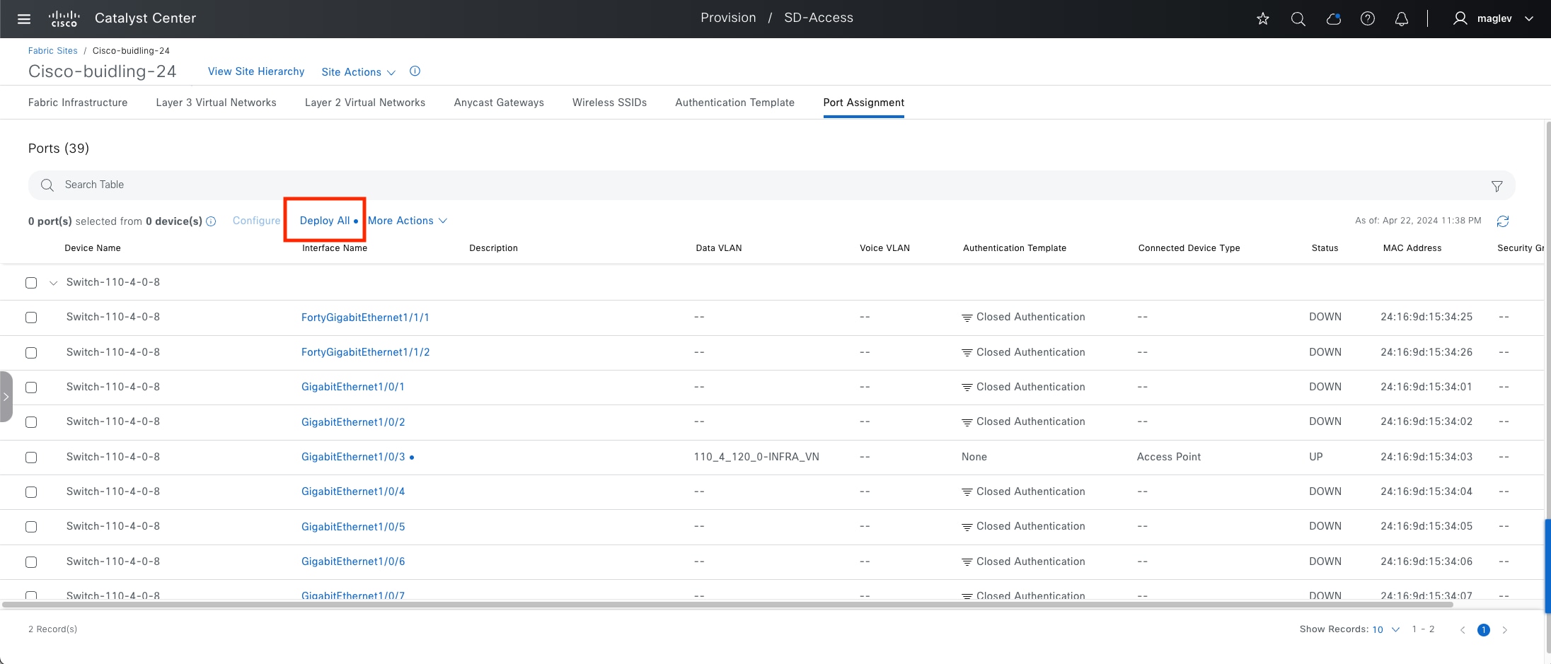
Procedure 2. APs through Catalyst Center PnP process
Step 1. Configure option 43 for the AP DHCP scope in the DHCP server pointing to Catalyst Center IP fabric interface IP with the ACSII value 5A1D; B2;K4;I120.1.1.1;J80, where 120.1.1.1 is the Catalyst Center IP address in the sample shown.
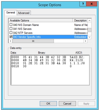
Step 2. Connect your AP device to GI1/0/3. From the menu icon button, choose Provision > Plug and Play.
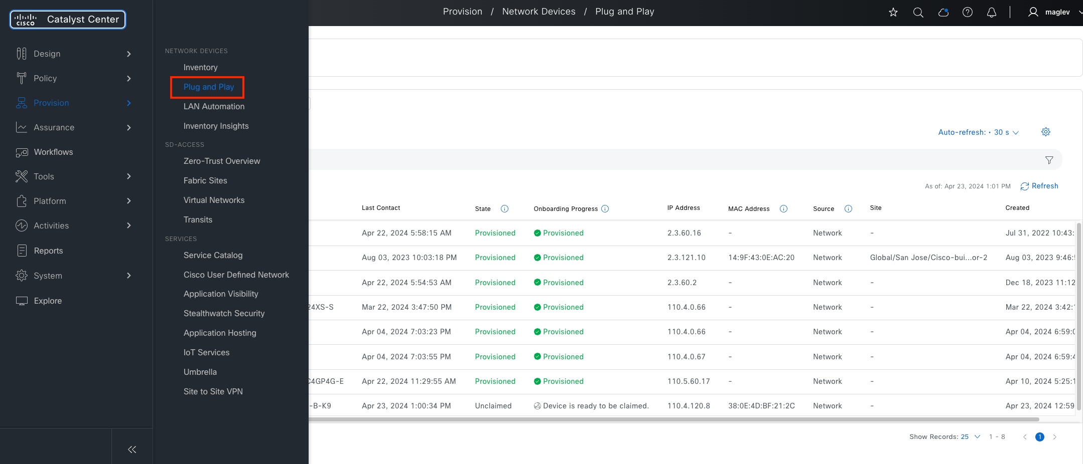
Step 3. Locate the new AP from the Unclaimed status category.
Step 4. Check the new AP check box then choose Actions > Claim.
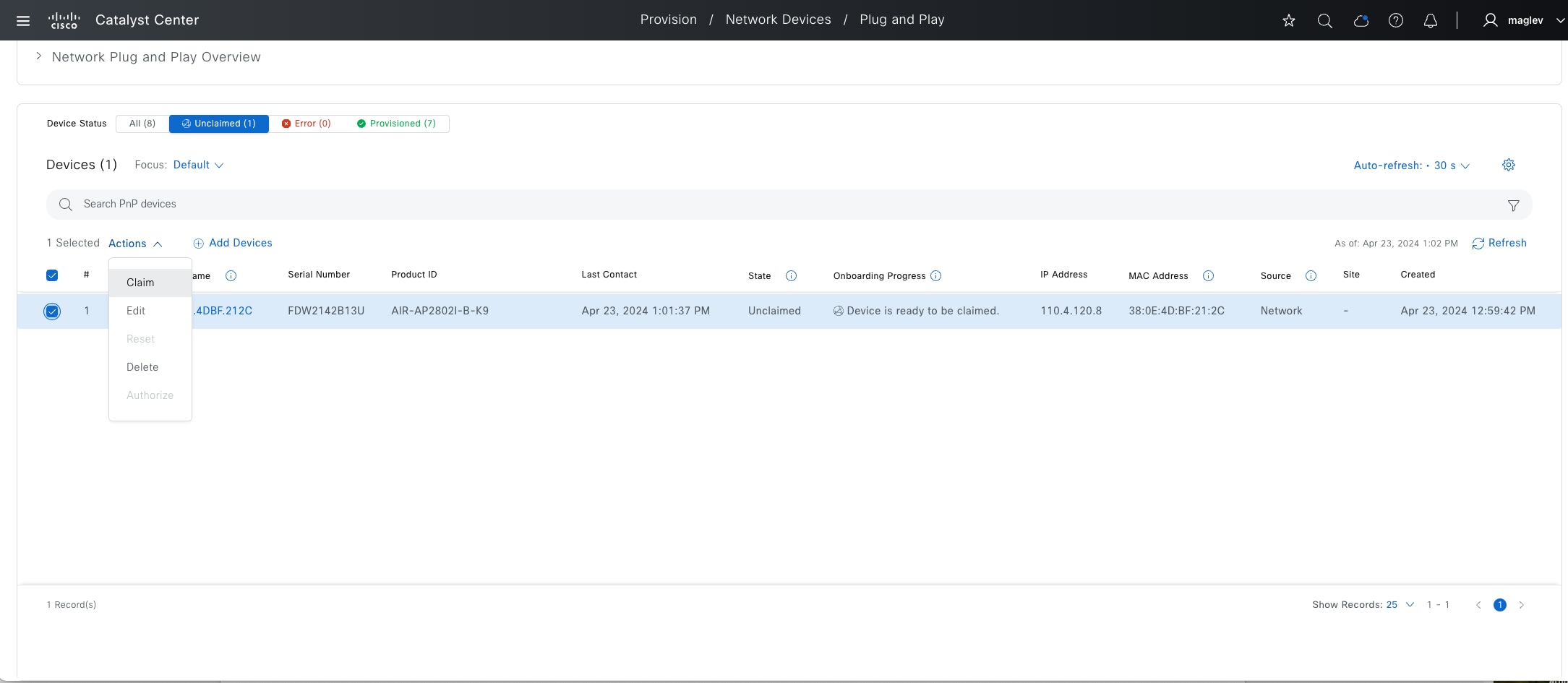
Step 5. In the Claim workflow, use this configuration:
Assign Site: choose Cisco-building-24 and Floor-2
Assign Configuration > Radio Frequency Profile: select Typical
Provision Templates: optional
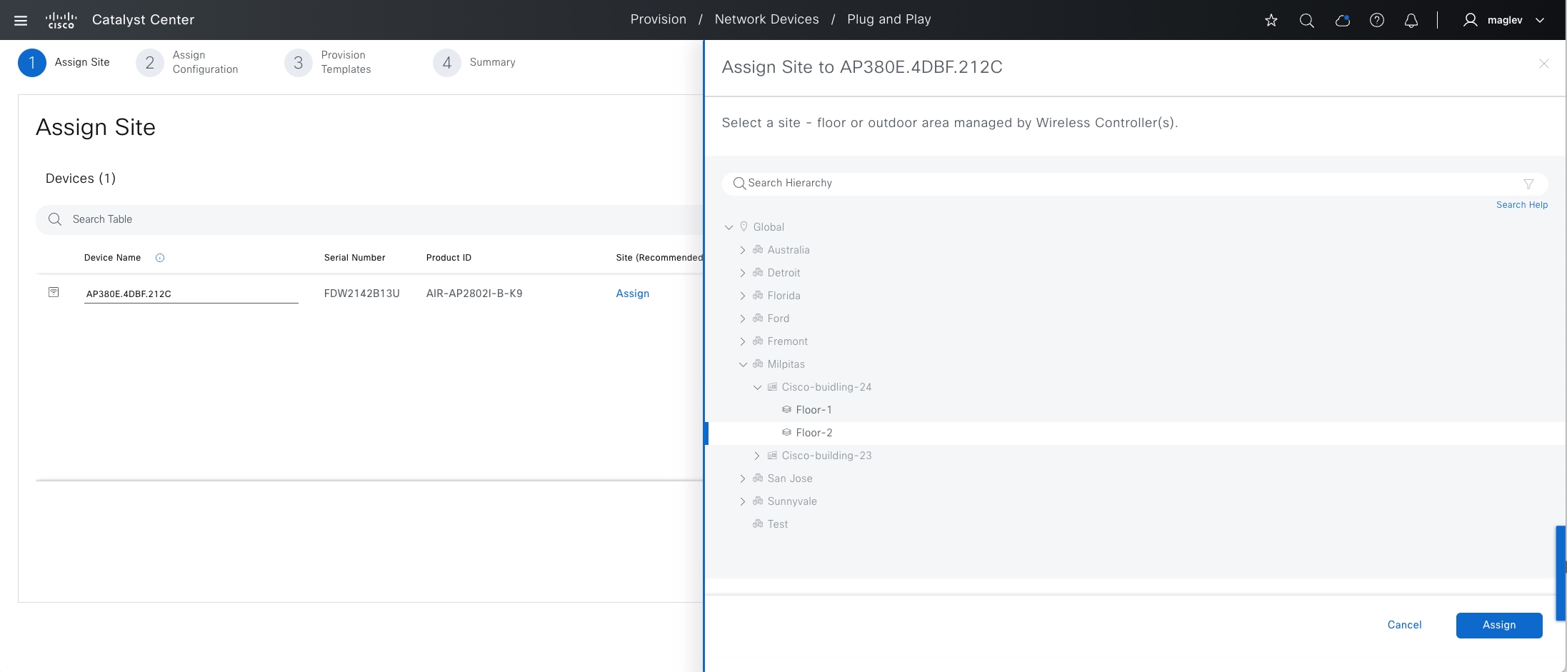
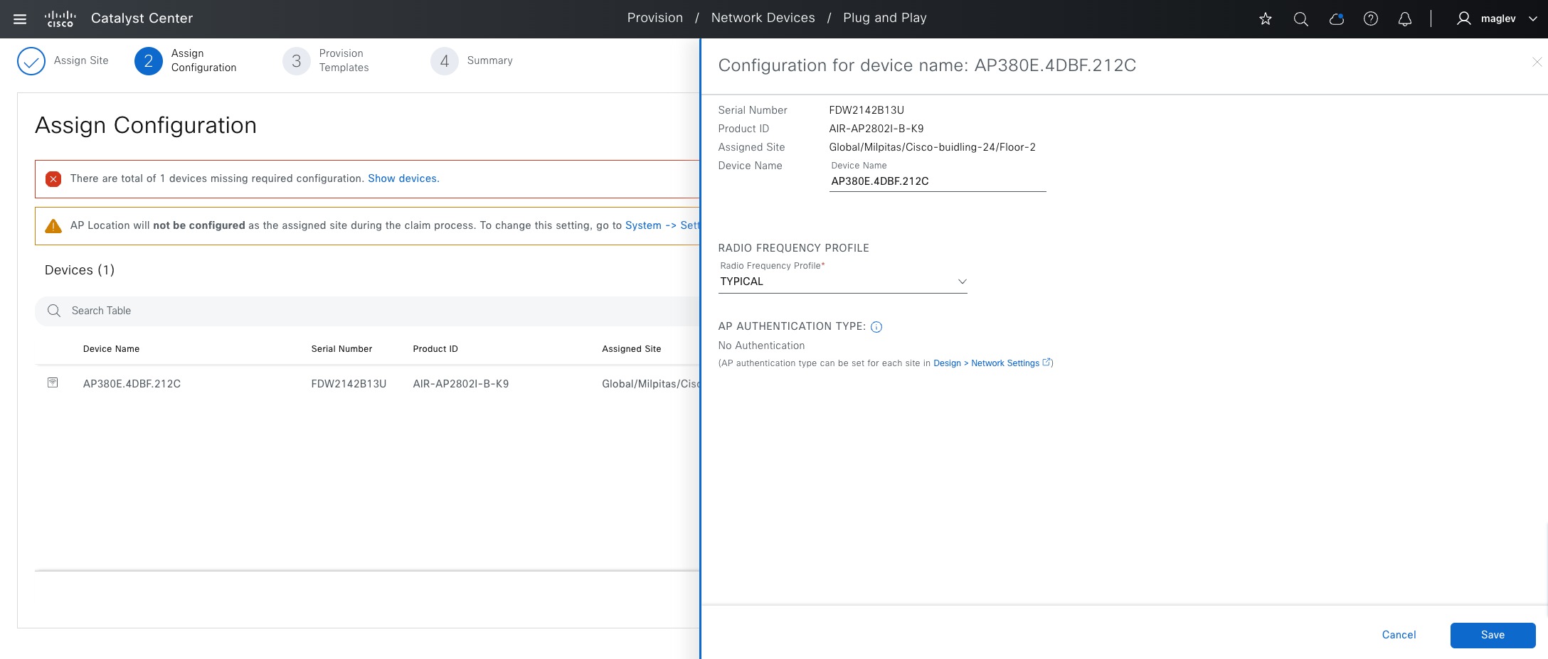
Step 6. Click Save to complete the Claim process.
Step 7. From the top-left corner, click the menu icon and choose Provision > Inventory to verify.
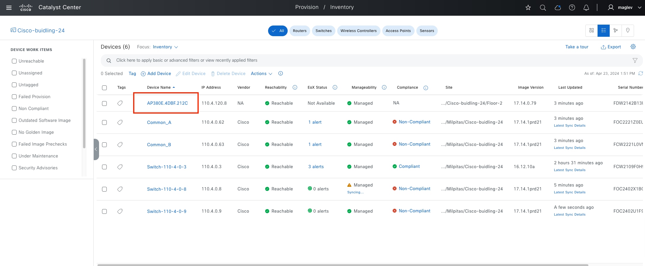
Step 8. On the embedded wireless controller, use the command show ap summary to check Common-B.
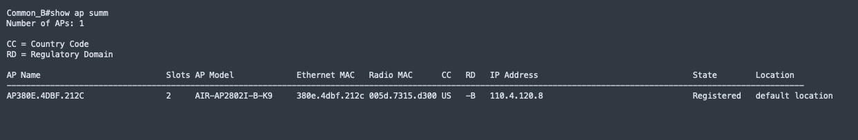
Procedure 3. Onboard APs in OTT deployment
AP onboarding with Catalyst Center is supported for CUWN OTT deployment and it is the same as fabric AP onboarding, which requires AP pool, port assignment on the connected fabric edge (Autoconf when there is no site-level authentication) and PnP process. However, Flexconnect OTT requires manual configuration on port assignments.
A fabric edge port connecting to the AP must be configured as a trunk port with a native VLAN defined to allow FlexConnect VLAN traffic.
It is recommended to use the Catalyst Center CLI template to deploy your configuration. This design and deployment guide does not discuss templates. See the Catalyst Center User Guide, section ‘Create Templates to Automate Device configuration Changes’.
Sample template configuration:
● ap_interface: interface connected to AP
● native_VLAN: VLAN used for AP connectivity to wireless controller
● allowed VLAN range: VLANs used for local flex connectivity
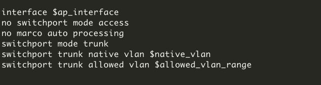
Onboard an extended node and a policy extended node
Similar to an AP, an extended node is connected to a fabric edge or another extended node. The IP pool for an extended node is required in INFRA_VN.
An extended node can be:
● Extended node
● Policy extended node
● Supplicant-based extended node (SBEN)
Policy extended nodes are extended nodes that support security policy within the VN. Policy extended node devices include Cisco Catalyst Industrial Ethernet (IE) 3400, IE 3400H, IE9300 Heavy Duty series switches, and Cisco Catalyst 9000 series switches that run Cisco IOS XE Release 17.1.1s or later. Cisco Digital Building series switches, Cisco Catalyst 3560-CX switches, and Cisco Industrial Ethernet 4000, 4010, and 5000 series switches cannot be configured as policy extended nodes.
Catalyst Center automatically configures the port channel on an extended node or a policy extended node and its upstream device. An SBEN and its upstream device are configured using a single physical link.
SBENs are Policy extended node devices that receive an IEEE 802.1x (Dot1x) supplicant configuration and are onboarded into the Cisco SD-Access network only after a complete authentication and authorization. To onboard a supplicant-based extended node device, the authenticator port on the fabric edge must be configured with a Closed Authentication Template.
Platforms supporting SBEN onboarding include:
Fabric edge or FiaB
Cisco Catalyst 9000 Series – C9300, C9400, C9500, and C9500H switches that operate Cisco IOS XE 17.7.1 or later.
SBEN
Cisco Catalyst 9000 Series – C9200, C9300, C9400, C9500, and C9500H switches that operate Cisco IOS XE 17.7.1 or later.
A device is onboarded according to the license of its extended node neighbor and its own license:
● If the neighbor is operating with an Essentials license, the device is onboarded as a standard extended node, regardless of its license.
● If the neighbor is operating with an Advantage license, the device is onboarded as a standard extended node if it has an Essentials license.
● If the neighbor is operating with an Advantage license, the device is onboarded as a policy extended node if it has an Advantage license.
● If the device has more than one neighbor, and those neighbors have different license levels, the device is onboarded as a standard extended node, regardless of its license.
The procedures in this section demonstrate the onboarding of an policy extended node and an SBEN in the fabric site Cisco‑building-24.
Note: PnP Device Authorization enables device authorization on Catalyst Center. When enabled, PnP devices in the extended node onboarding process or the LAN automation workflows need to be authorized in the Plug and Play window.
From the top-left corner, click the menu icon and choose System > Settings then click PnP Device Authorization in the left side pane to enable or disable this feature.
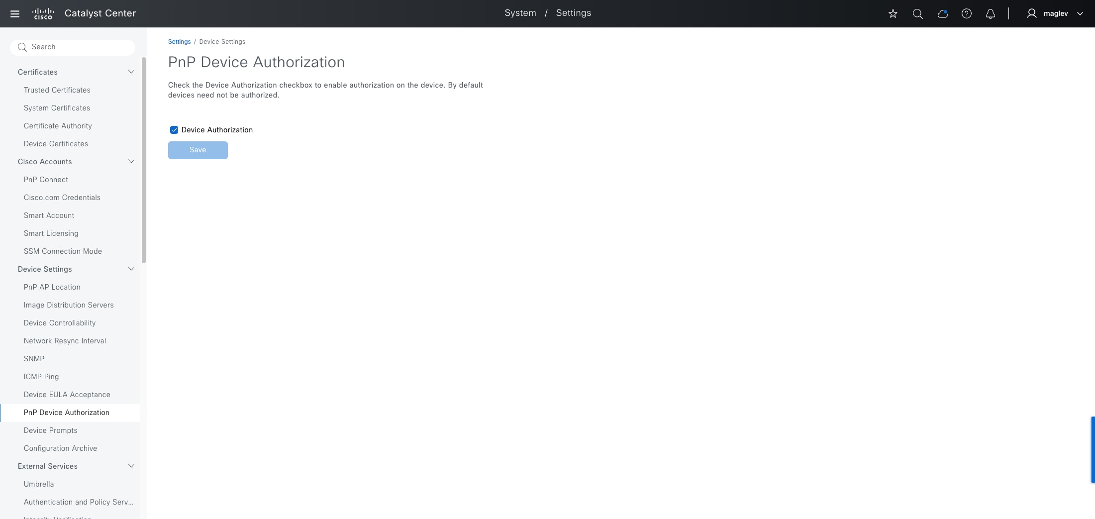
Procedure 1. Configure an extended node pool
The extended nodes pool was configured in Procedure 1: Add an anycast gateway in INFRA_VN.
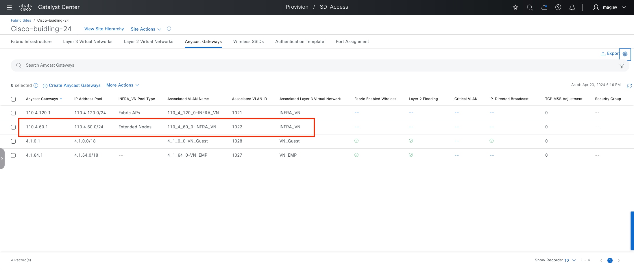
Procedure 2. Onboard a policy extended node
Cisco-building-24 uses the site-level Closed Authentication template. To onboard an extended node or policy extended node, manually configure the port channel before onboarding. If the site-level authentication template is set to No Authentication, Catalyst Center configures the port channel automatically.
PnP device authorization is disabled in this example procedure.
Step 1. From the top-left corner, click the menu icon and choose Provision > Fabric Sites, click the table view icon in the top right, click the Port Assignment tab then choose More Actions > Create Port-Channel.
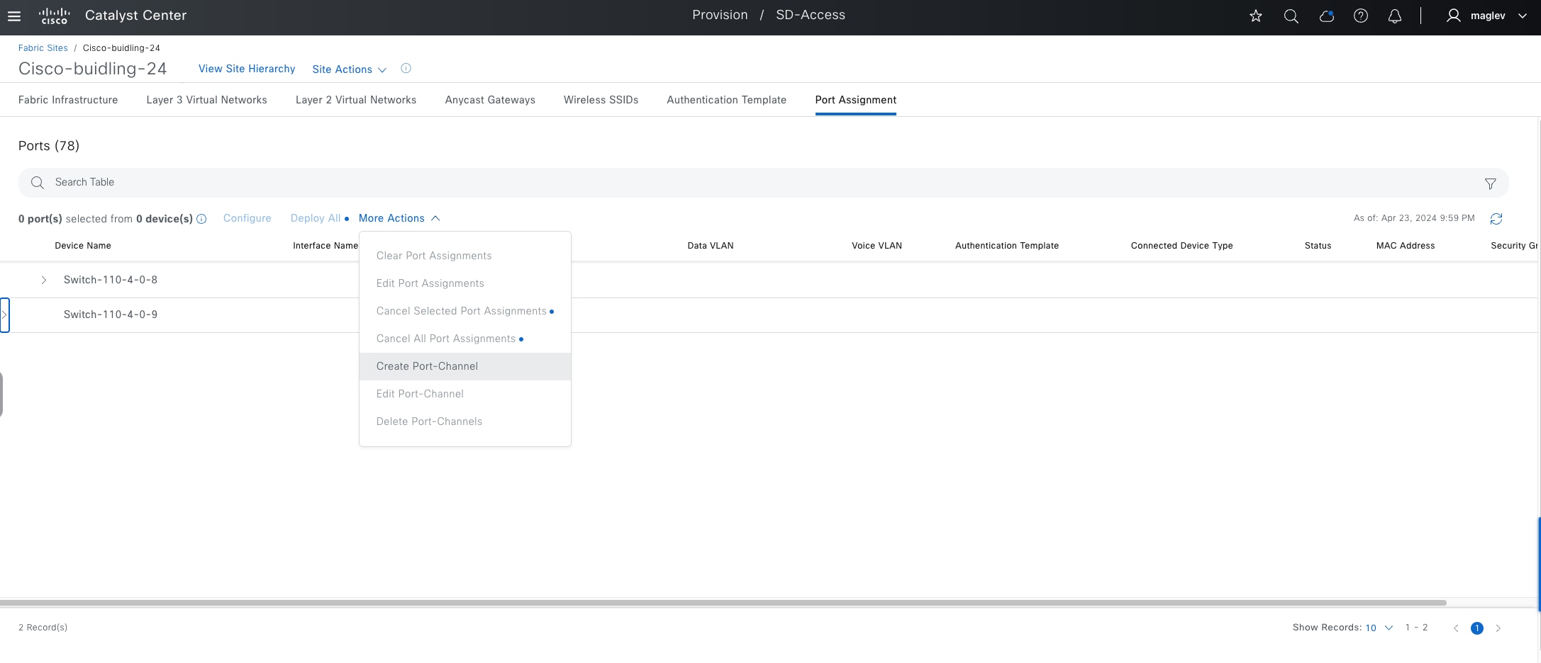
Step 2. Choose Switch-110-4-0-9 as the fabric edge for this example case.
Step 3. In the Create a Port Channel window, choose Connected Device Type > Extended Node, choose Protocol > Port Aggregation Protocol then click Next.
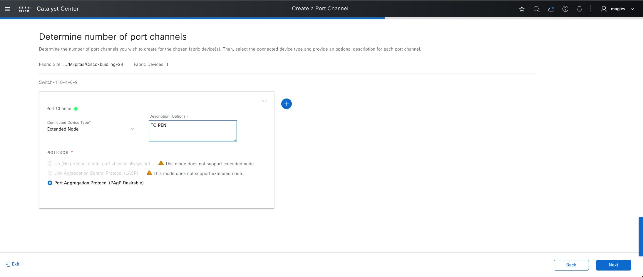
Step 4. To provision the device, select the ports to be connected to the extended node, click Next, then complete the workflow.
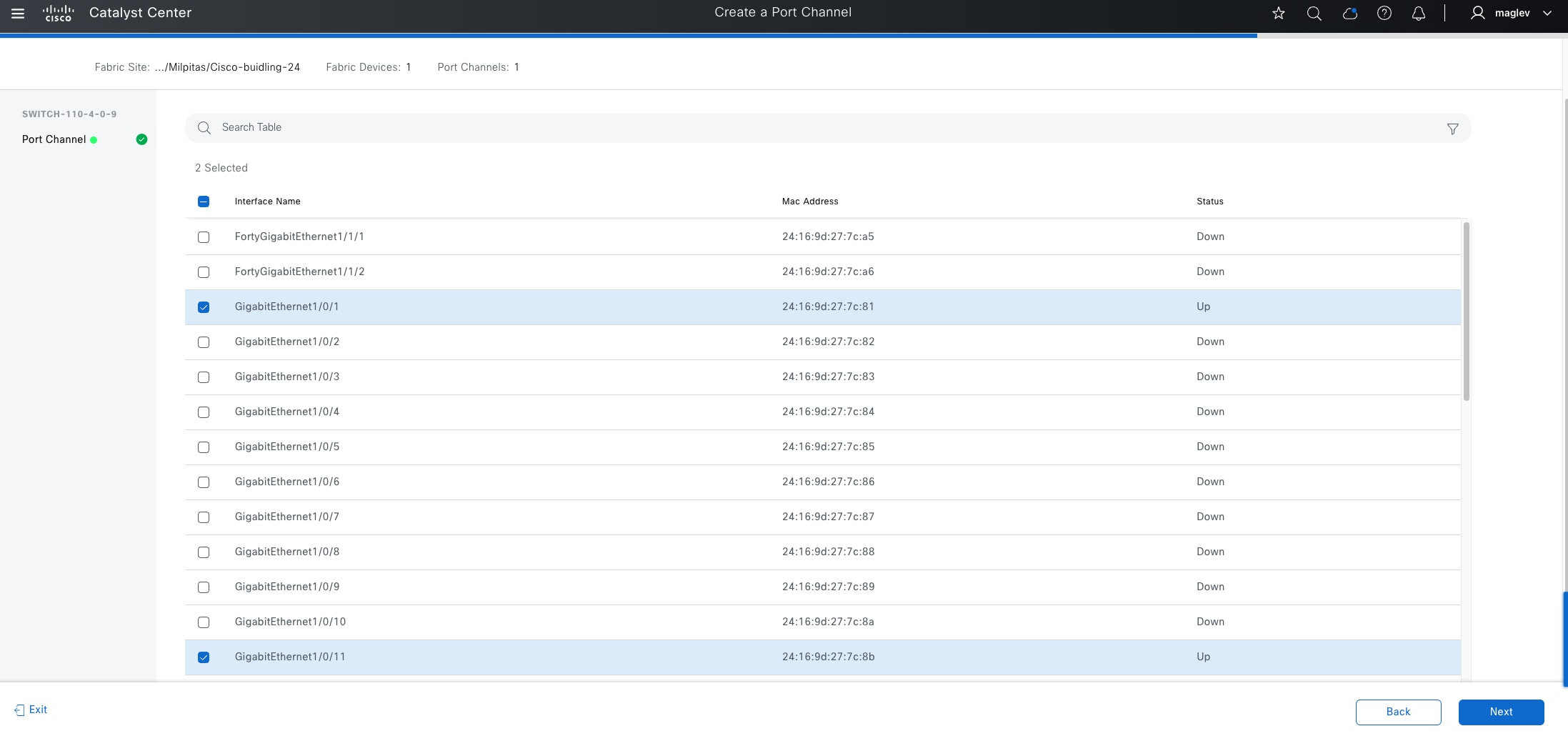
Step 5. Configure option 43 for the AP DHCP scope in the DHCP server pointing to Catalyst Center IP fabric interface IP with the ACSII value 5A1D; B2;K4;I120.1.1.1;J80, where 120.1.1.1 is the Catalyst Center address (same configuration as the AP pool).
Step 6. Connect the device to the fabric edge and wait for onboarding to complete. Unlike AP onboarding, there is no claim process requirement. Catalyst Center automatically claims and onboards devices to the fabric sites.
Step 7. Monitor from the Plug and Play window. From the top-left corner, click the menu icon and choose Provision > Plug and Play then click Unclaimed.
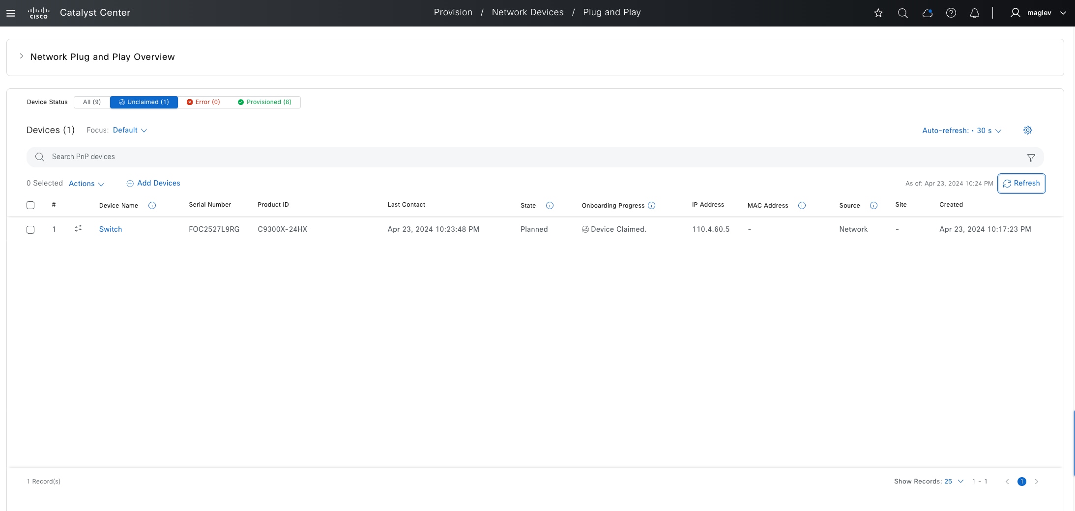
Step 8. Monitor from the fabric site window. From the top-left corner, click the menu icon and choose Provision > Fabric Sites, click the table view icon in the top right, click the Cisco-building-24 text link, then choose Site Actions > Show Task Status.
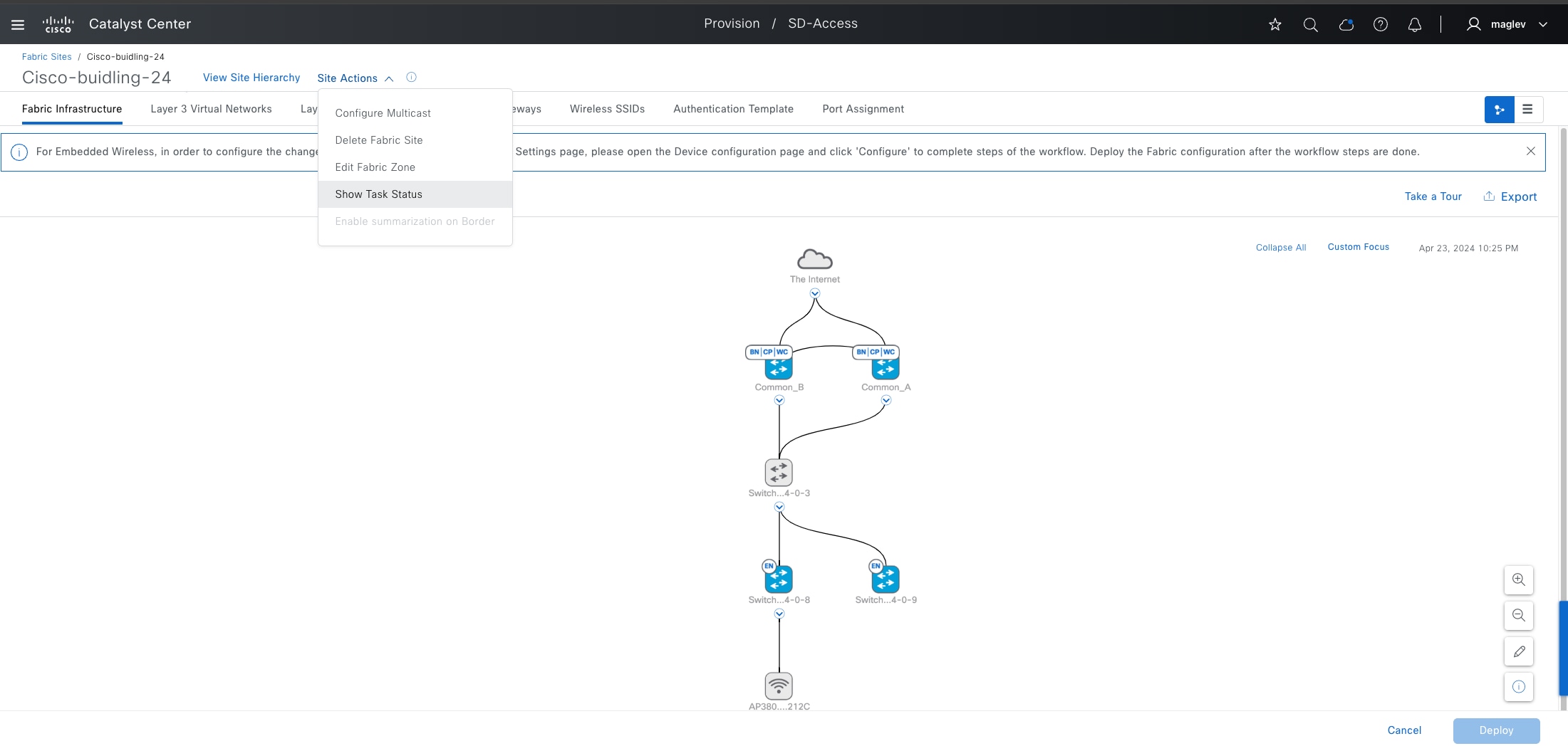
Step 9. To monitor the onboarding progress, in the Task Monitor slide-in pane, click Filter > Extended Node.
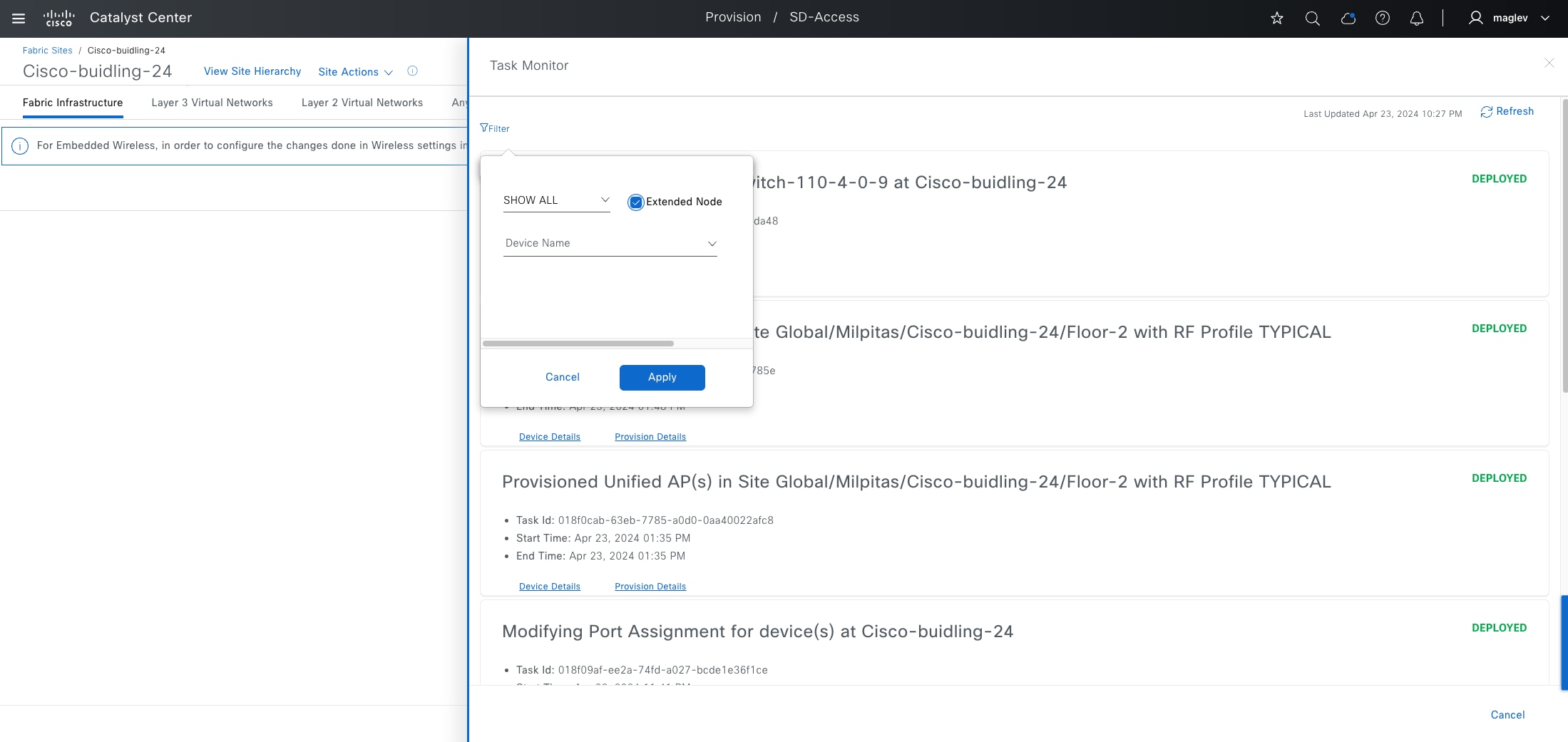
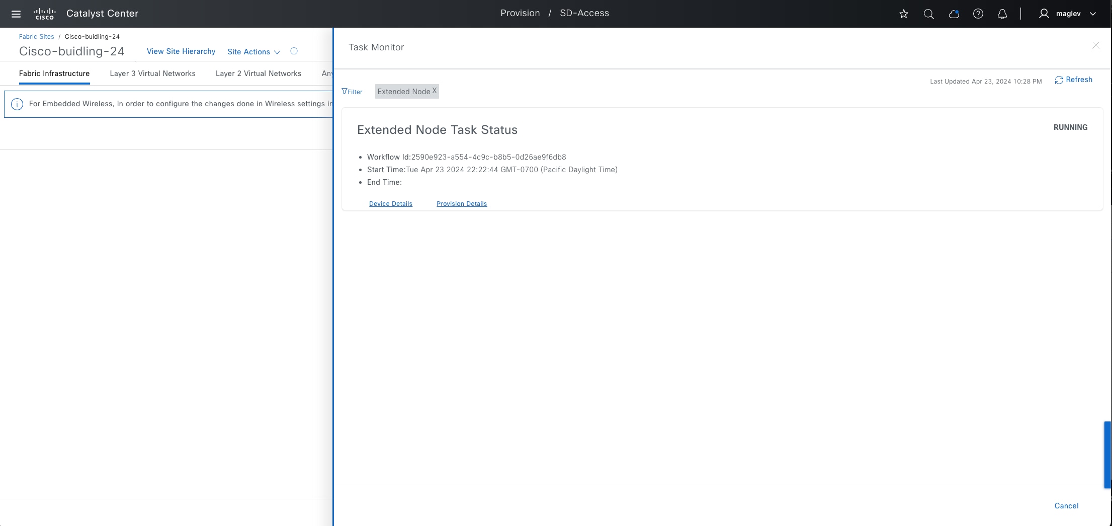
After the onboarding completes, the device appears blue in the Fabric Infrastructure tab with the fabric role marked EX.
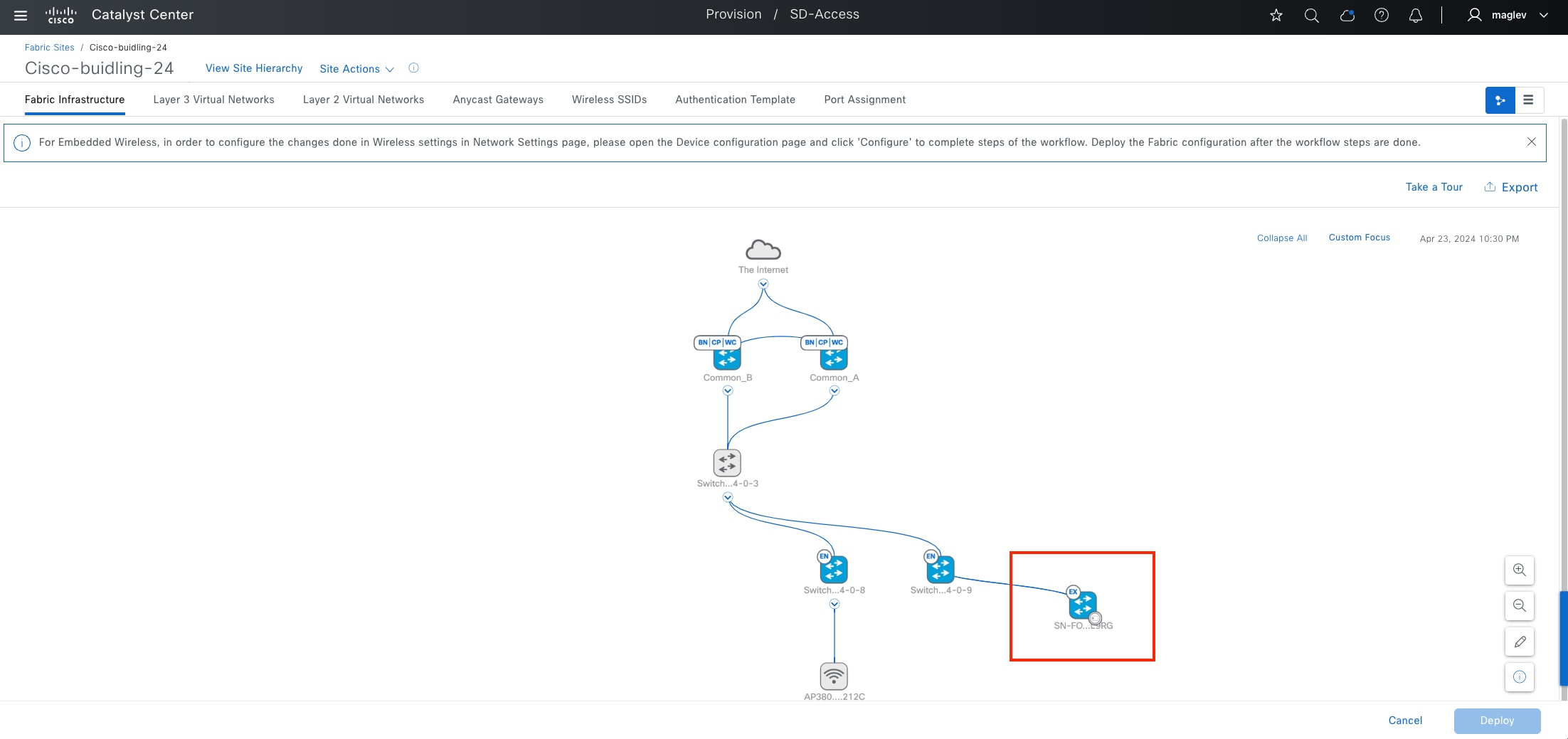
Step 10. Repeat the procedure to onboard more policy extended nodes, as needed. Multiple extended nodes can be onboarded at the same time.
Onboard an SBEN
Onboarding an SBEN requires an SBEN pool and Cisco ISE.
Procedure 1. Configure SBEN Pool
INFRA_VN only supports one AP pool and one extended node pool. To onboard SBEN, the extended node pool needs to be enabled with SBEN pool capacity.
Step 1. Disable Bridge Protocol Data Unit (BPDU) Guard on the fabric site. Click on the Authentication Template tab and deactivate the Enable BPDU Guard option then click Deploy.
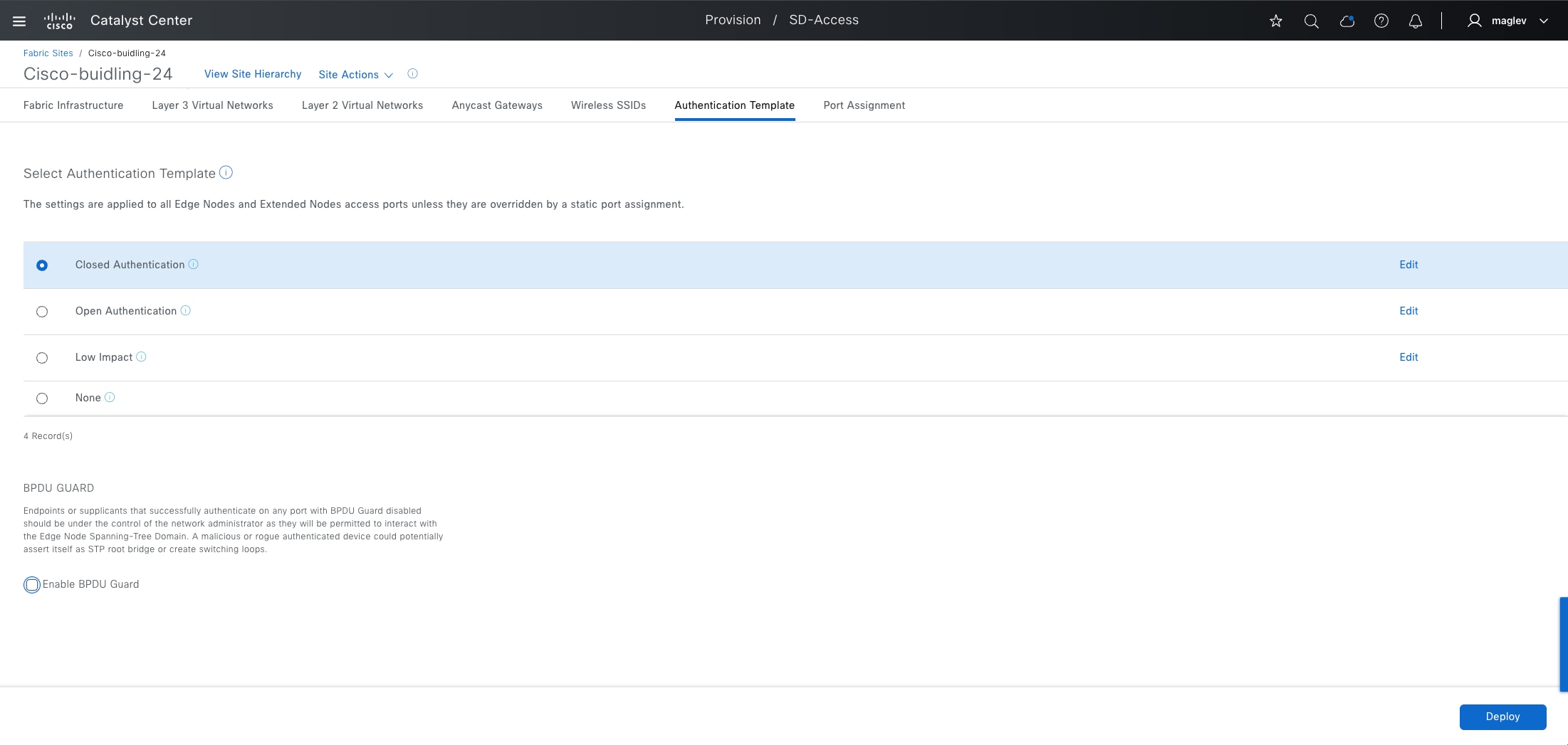
Note: If the extended node pool is also used in a fabric zone, repeat the same procedure for the zone.
Step 2. Click the Anycast Gateways tab. Choose the extended pool then click More Actions > Edit Anycast Gateways.
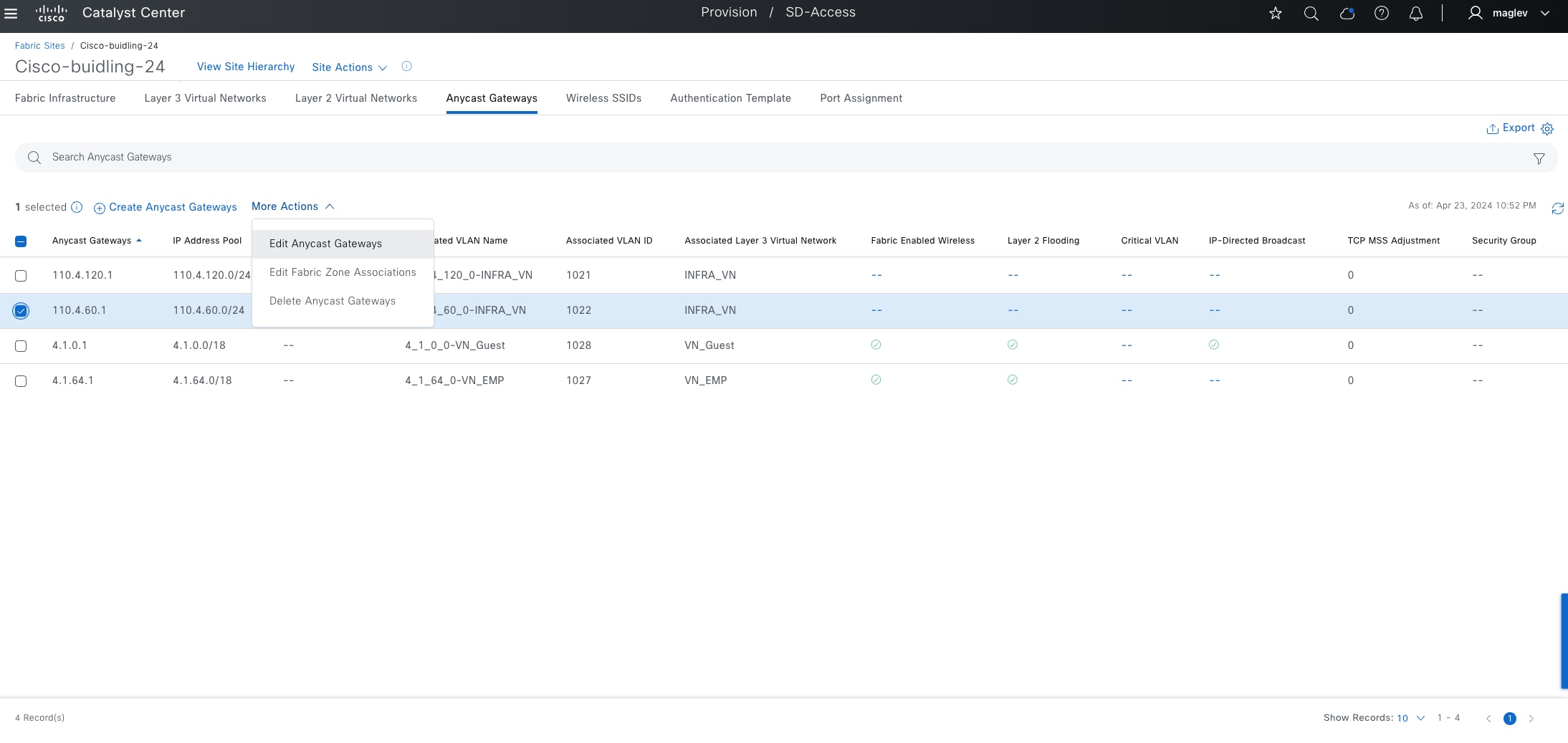
Step 3. Check the Supplicant-Based Extended Node Onboarding check box then complete the workflow.
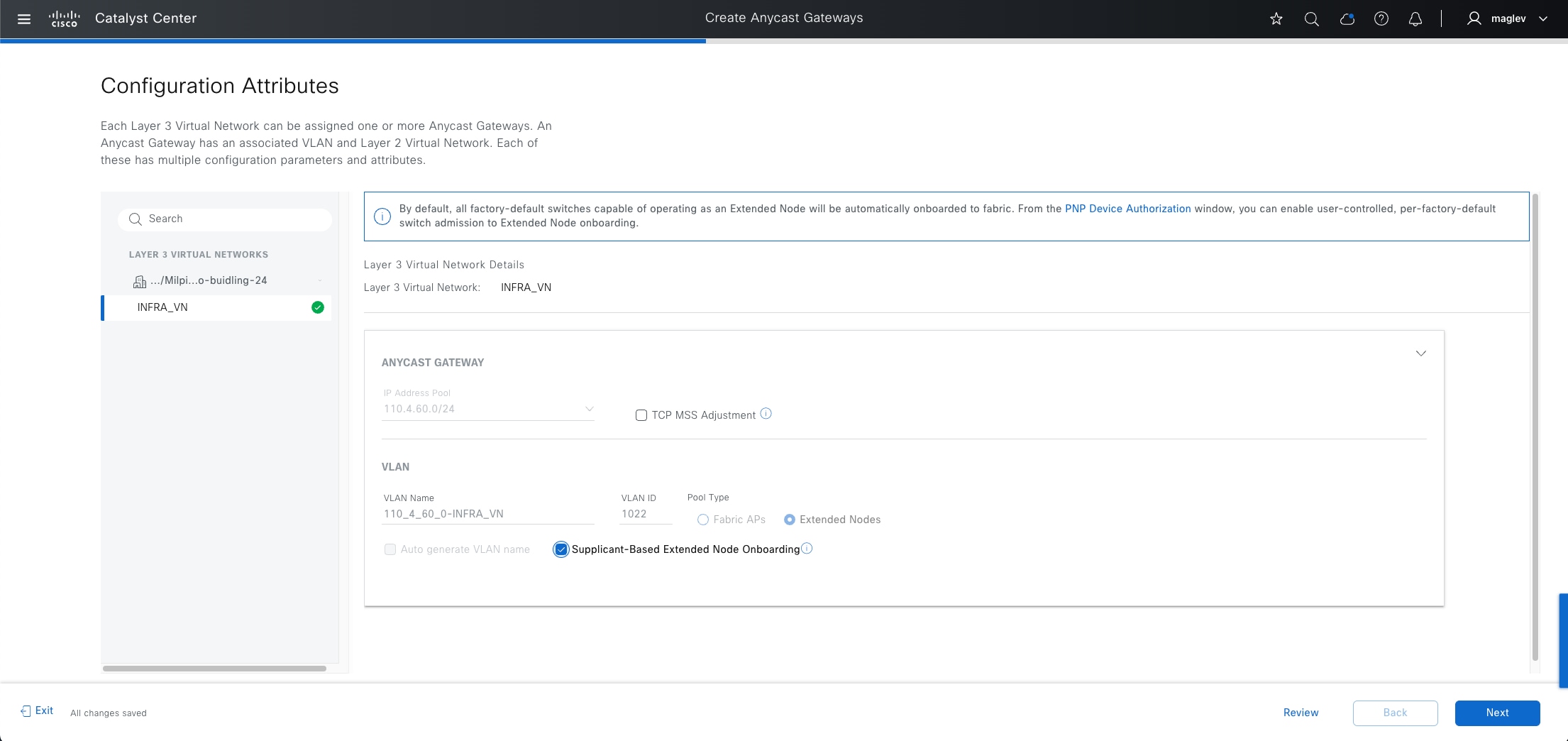
Procedure 2. Configure policies in Cisco ISE
Configure Cisco ISE and ensure that it is running Software Release 3.1 or later.
Step 1. Download the CA certificate from Catalyst Center. Click System > Settings > Certificate Authority > Download.
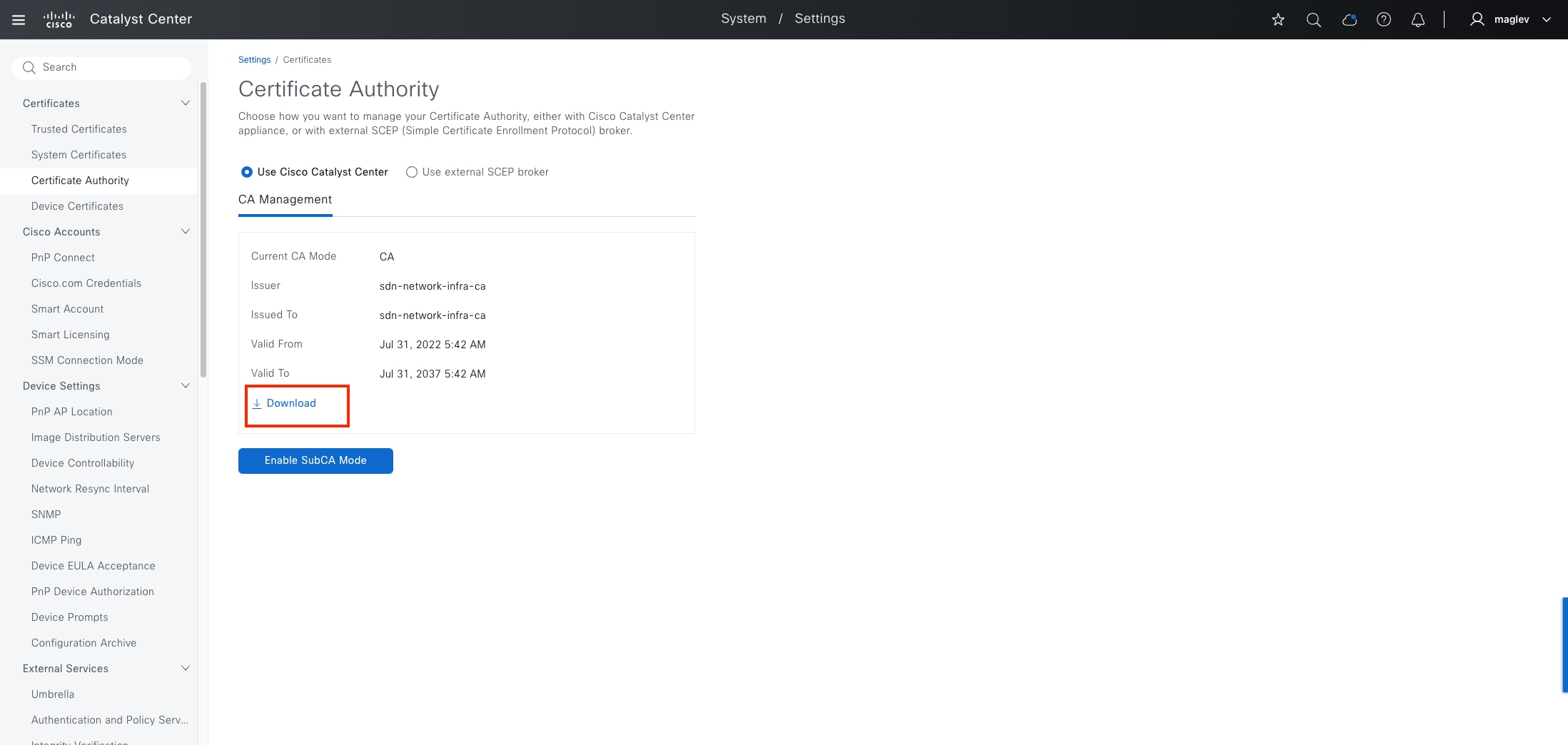
Step 2. Import the CA certificate into Cisco ISE. From the Cisco ISE home window, click Administration > System > Certificates > Trusted Certificates > Import.
Step 3. In the Import window, check the Trust for client authentication and Syslog check box.
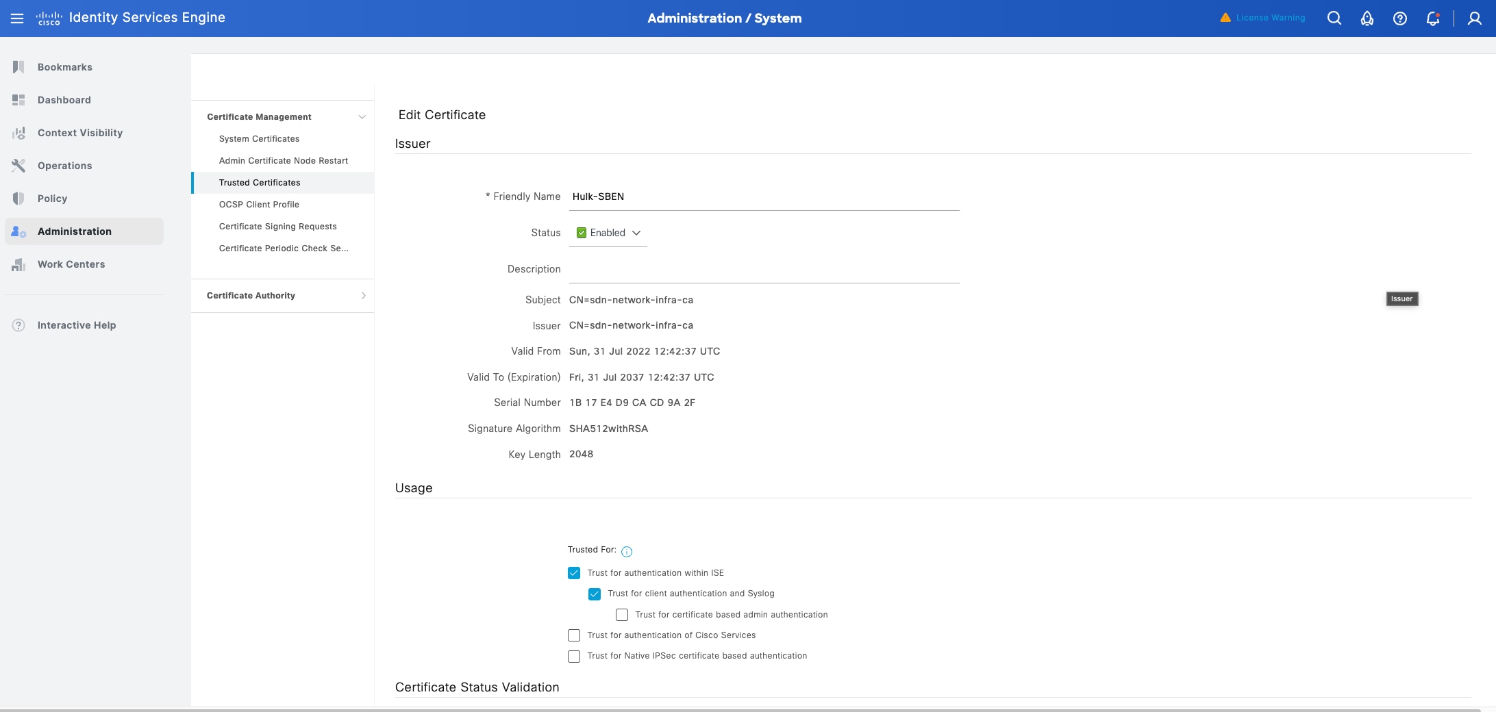
Step 4. Configure the policy. Click Policy > Policy Elements > Results > Authorization > Authorization Profiles, configure the three profiles with the respective radius attributes provided in the Table 25.
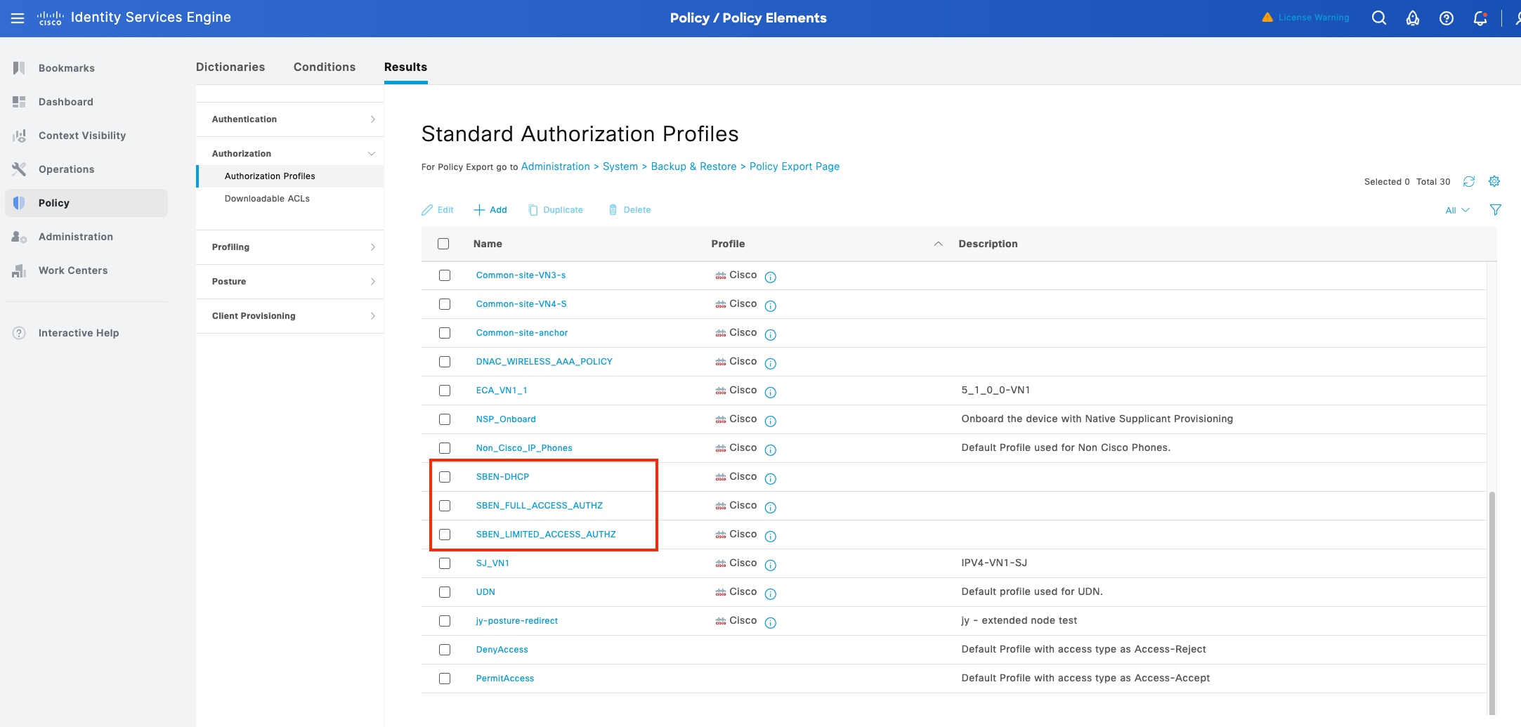
Table 25. Profile configurations
| Name |
Access Type |
Filter-ID |
cisco-av-pair = interface-template-name |
| SBEN-DHCP
|
ACCESS_ACCEPT |
SBEN_DHCP_ACL.in |
|
| SBEN_LIMITED_ACCESS_AUTHZ |
ACCESS_ACCEPT |
SBEN_MAB_ACL.in |
SWITCH_SBEN_MAB_TEMPLATE |
| SBEN_FULL_ACCESS_AUTHZ |
ACCESS_ACCEPT |
|
SWITCH_SBEN_FULL_ACCESS_TEMPLATE |
Step 5. Define the device profiling policy. Click Policy > Profiling > Profiling Policies.
a. In the Policy / Profiling window, add a new DHCP-v-i-vendor-class condition for the Cisco-Device: Cisco-Switch policy. Choose Associated COA type > Global Settings.
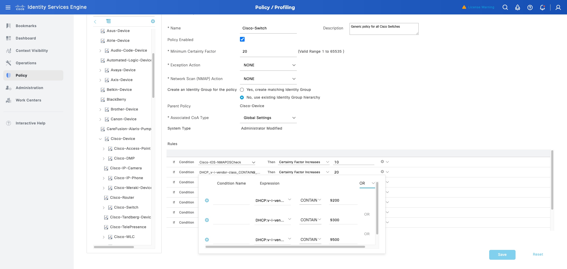
b. Under Cisco-Switch, create a new child policy for the supplicant device, and apply the CdpCachePlatform and V-I-Vendor-Class conditions.
Ensure that the Minimum Certainty Factor value for the child policy is higher than that of the parent policy.
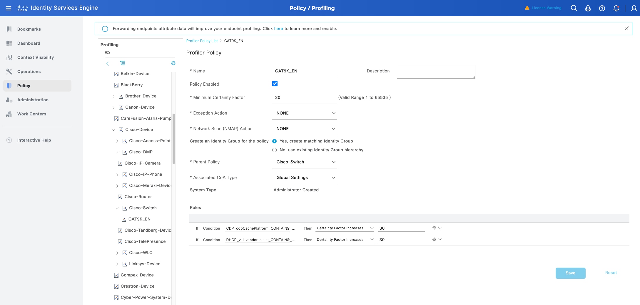
Step 6. Set the global Change of Authorization (CoA) type. From the Cisco ISE home window, click Work Centers > Profiler Settings then for CoA Type, select Reauth.
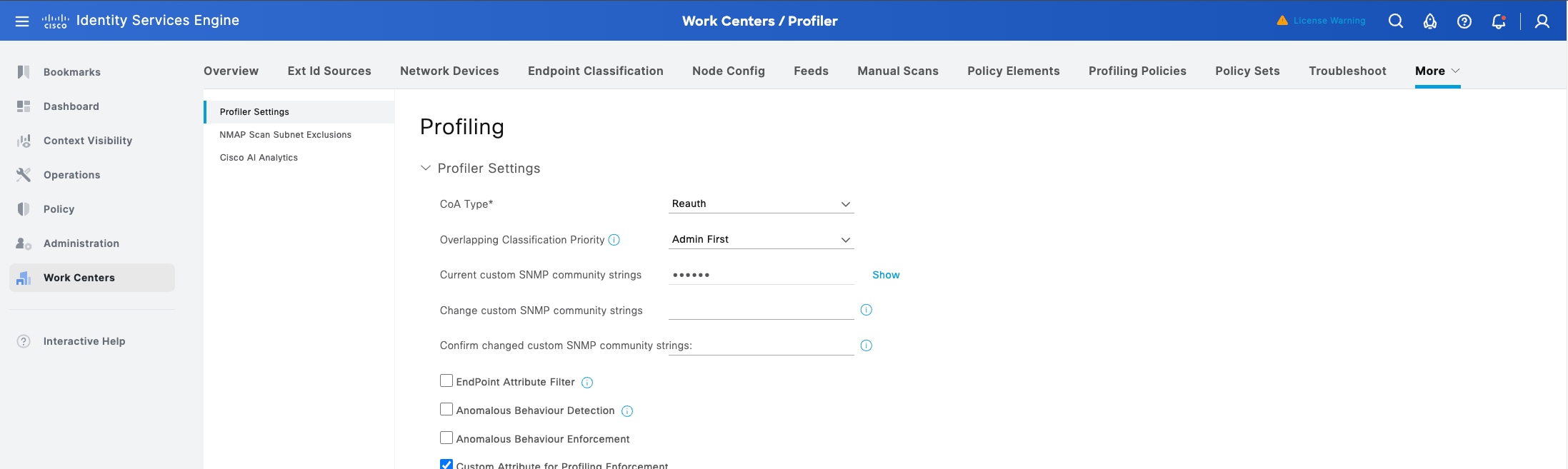
Step 7. Configure the Authorization Policy. Click Policy > Policy Sets > Default > Authentication Policy.
a. For the If User not found field, ensure that the default MAB policy is set to CONTINUE.
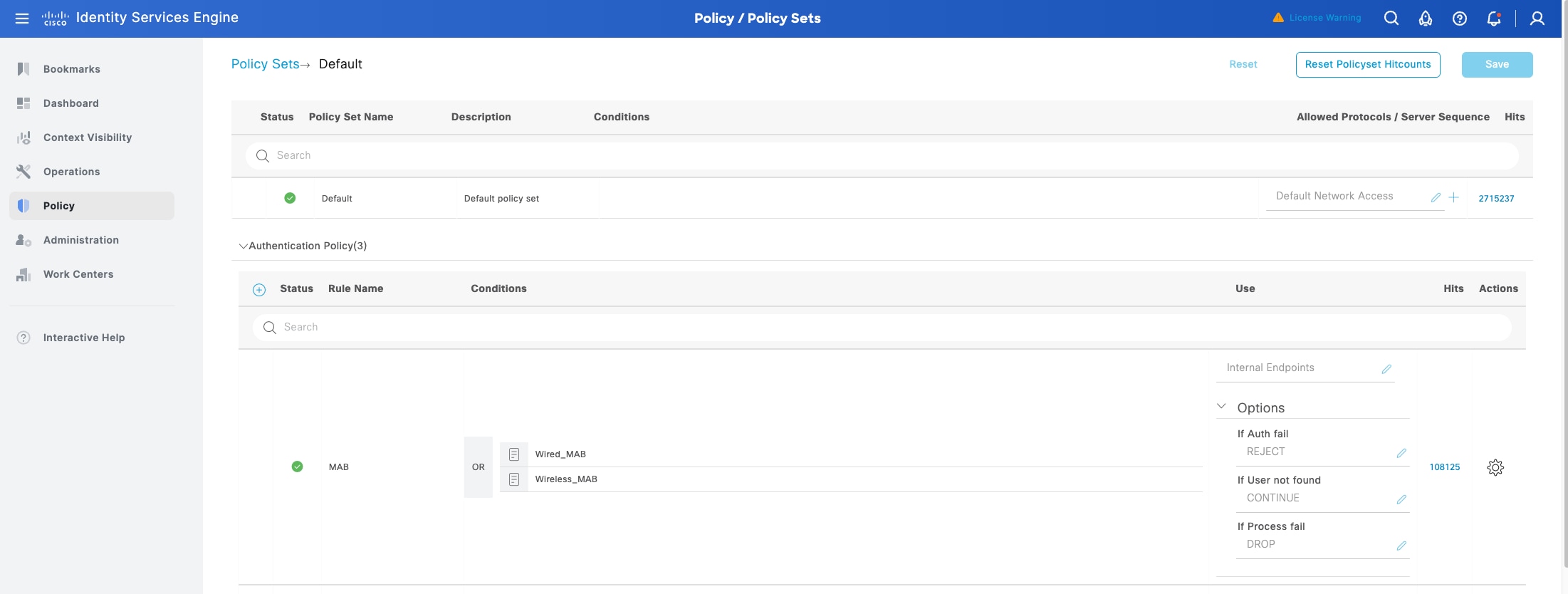
b. In the Policy Sets window, configure the authorization policies for the supplicant device and associate the policies with the authorization profiles that were created earlier (SBEN-DHCP, SBEN_LIMITED_ACCESS_AUTHZ, SBEN_FULL_ ACCESS_AUTHZ).
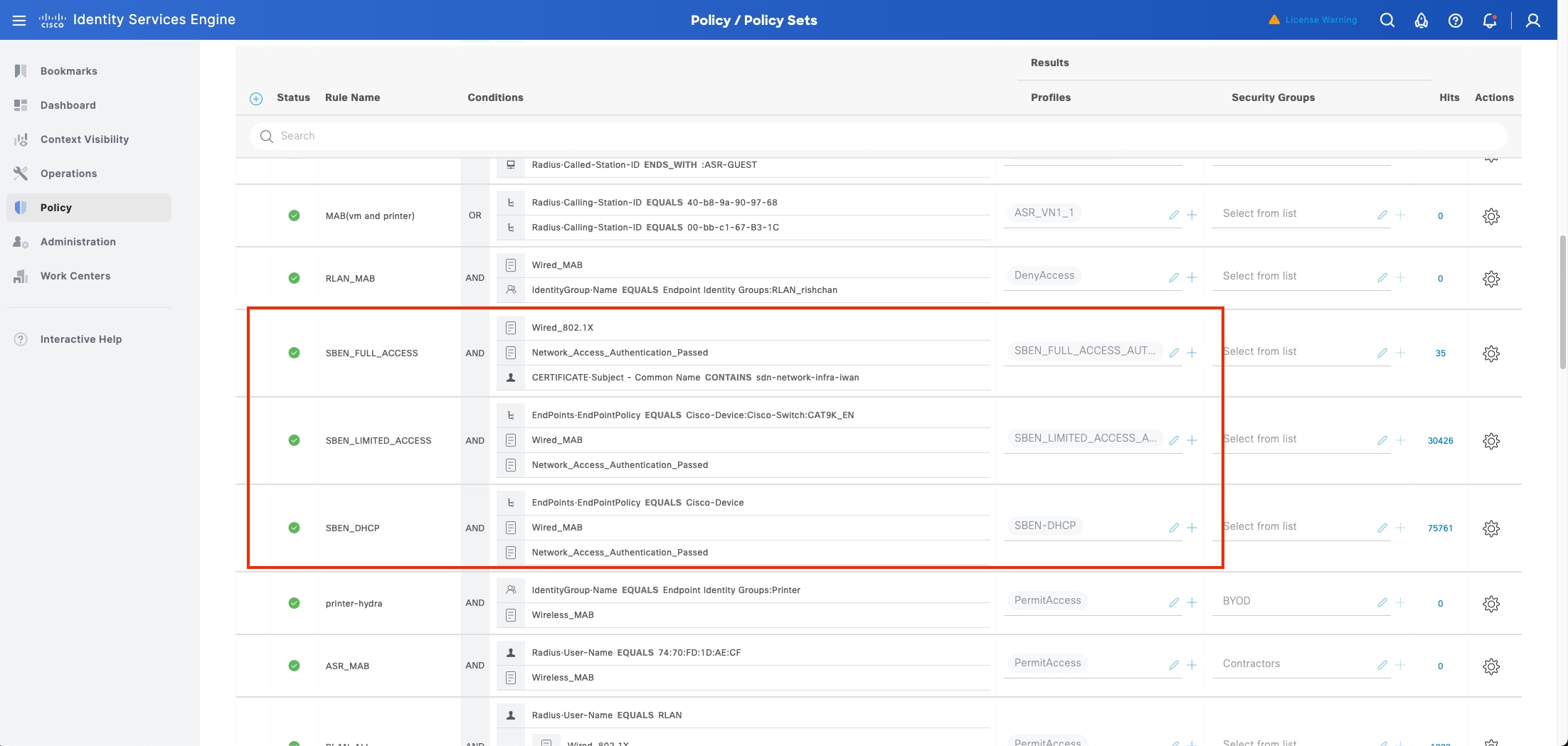
Procedure 3. Onboard supplicant-based extended node
Connect the new device to one of the Policy extended nodes onboarded with single link connection. PnP Device Authorization is enabled in this example.
Step 1. Monitor from the Plug and Play window. When the device status is Pending Authorization, click Actions > Authorize.
Note: Step 1 is required only if the PNP Device Authorization is enabled.
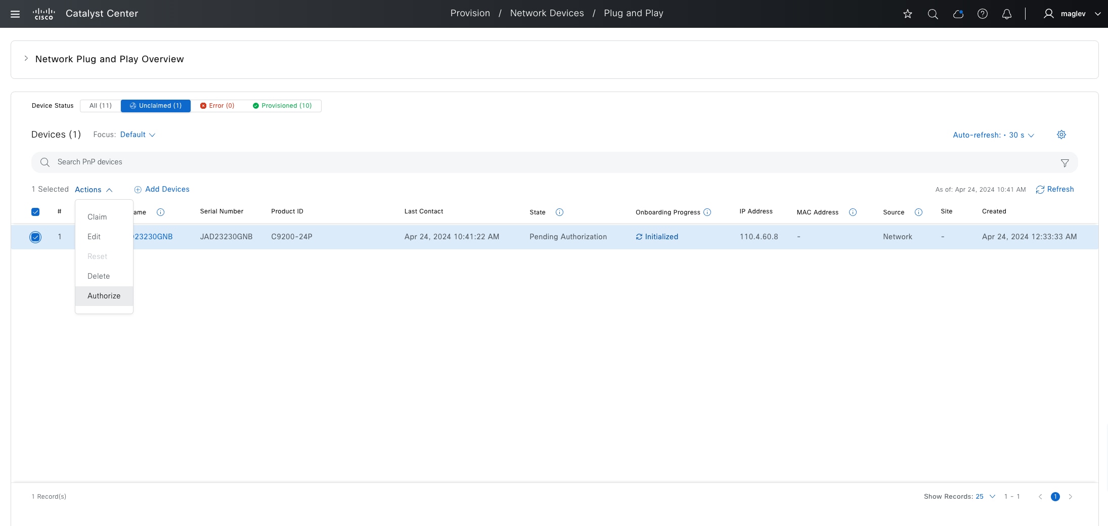
Step 2. Monitor Show Task Status from the fabric site.
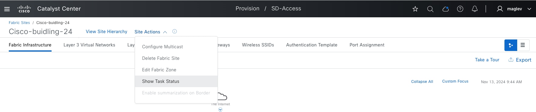
Onboarding is finished, and the device is added to the fabric.
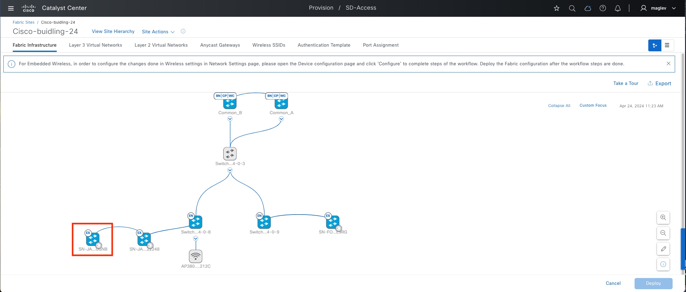
Note: In the onboarding, the new SBEN device is connected to another SBEN device. This is called a Daisy Chain.
Onboard clients
Besides AP and extended nodes, Port Assignment can also specify and configure physical ports for server device which requires trunk port and access ports for endpoint. Below example shows configuring several individual ports for Connected Device Type as User Devices and Endpoints and Trunking Device.
Step 1. From the top-left corner, click the menu icon and choose Provision > Fabric Sites, click the table view icon in the top right, click the Cisco-building-24 text link, click the Port Assignment tab, check the physical ports check boxes then click Configure.
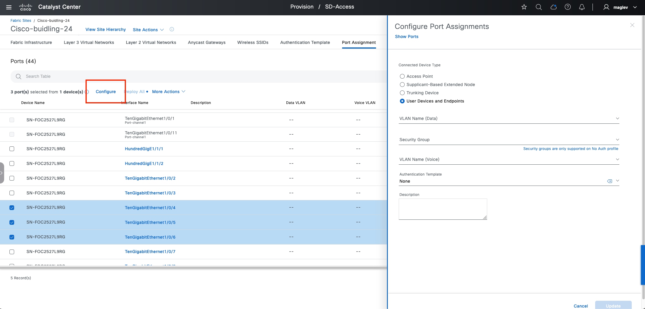
Step 2. Configure the needed information then click Update.
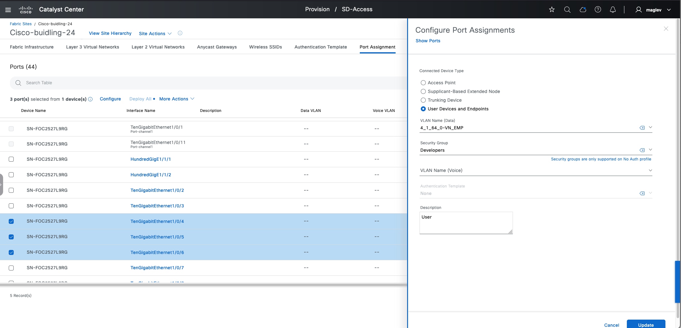
Step 3. Deploy All is marked with a dot to indicate there are some changes that need to be provisioned. Physical ports that have the pending changes are also marked with a dot.
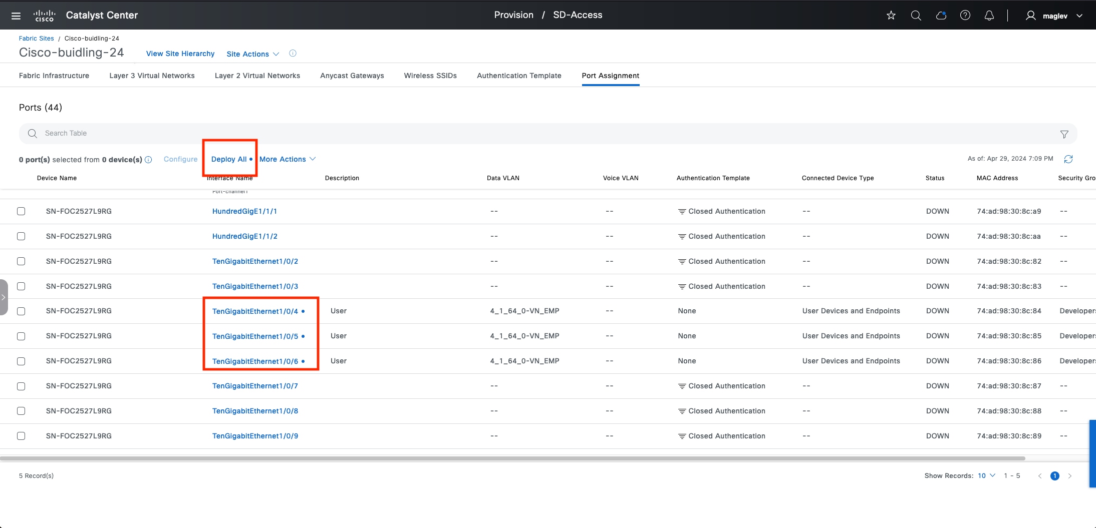
Step 4. Continue to configure other ports as Trunking Device then click Update.
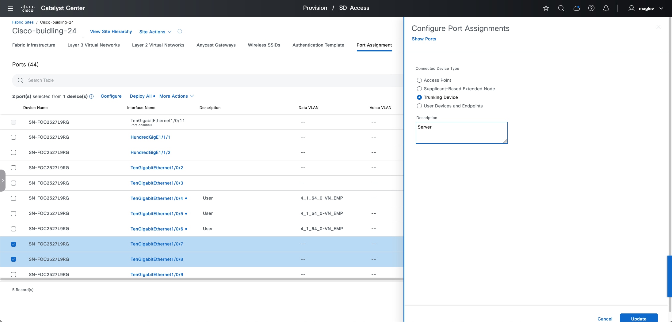
Step 5. Click Deploy All to deploy the changes to the device.
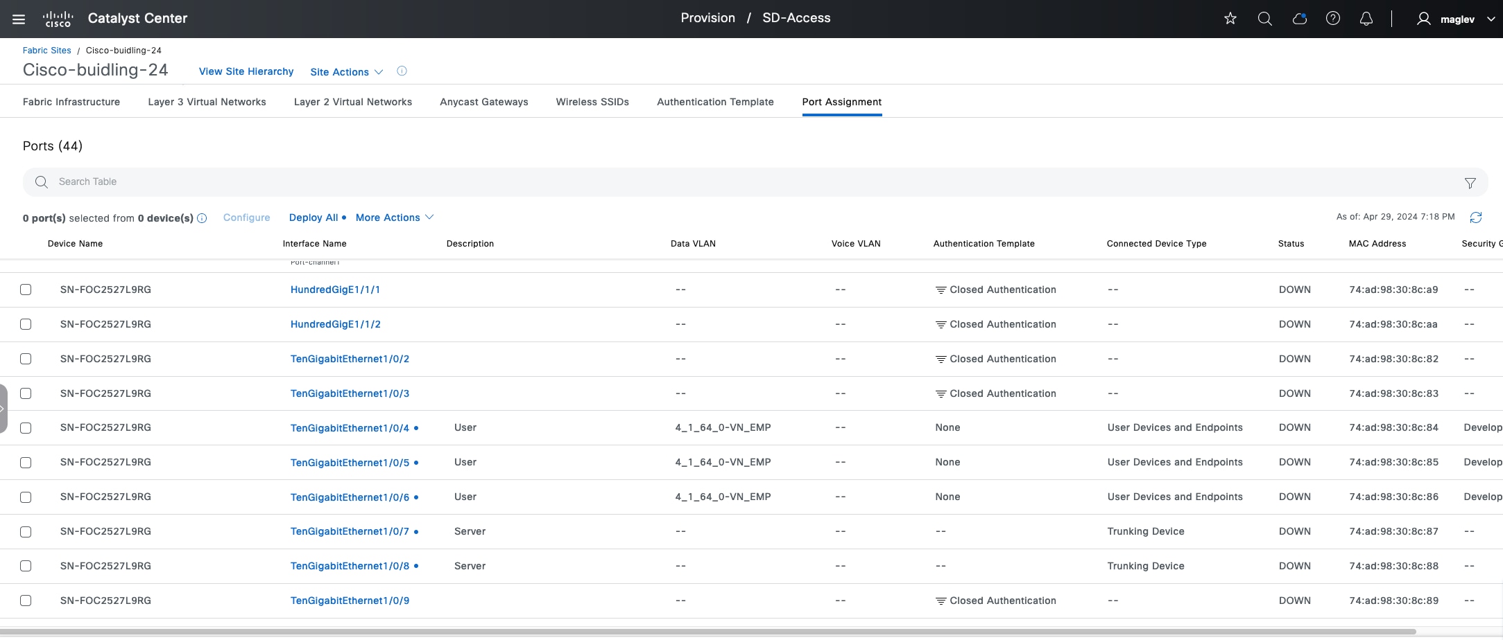
Step 6. Review the client information on the device.
The host is connected to an edge node or a PEN node. Use the command show access-session interface xx detail if it is onboarded with authentication.
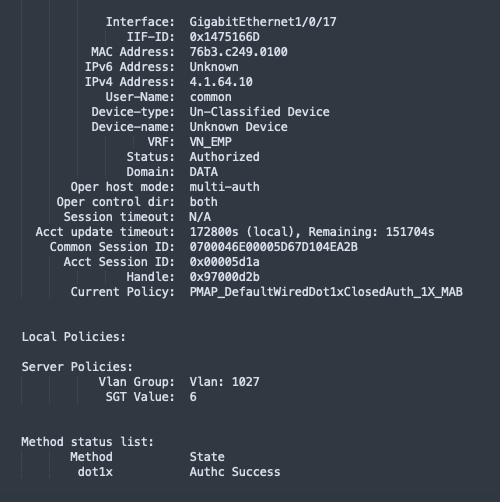
Wireless clients need to be checked on the wireless controller. Use the command show wireless client summary.
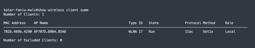
Also use the command show wireless client mac-address xx detail to review the details.
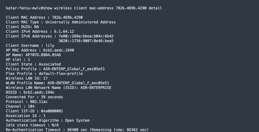
Modify fabric features
Certain fabric operations, such as enabling new fabric features in the anycast gateway and fabric borders, changing site-level authentication template, adding an anycast gateway to fabric site, performing port assignment, modifying or adding a fabric SSID, and so on are allowed in the Cisco SD‑Access workflows. The non-changeable features and attributes are normally grayed out in the GUI. For example, these operations are not allowed:
● Change fabric role:
Changing fabric role on a device requires deleting this device from fabric first, then adding back with the new role.
● Change Cisco SD-Access type:
If a fabric site is configured as LISP Pub/Sub or LISP/BGP, changing it to LISP/BGP or LISP Pub/Sub is not supported. Tear down the fabric site and rebuild the fabric.
● Move a fabric device to a different site:
If a device is provisioned to a site, it is not allowed to change it to a different site. Delete the device from fabric site and Inventory, then re-add or rediscover it and provision it to the new site.
● Configure VN anchoring:
It is not allowed to anchor a VN that is in use. Delete all the anycast gateways, de-associate the VN from fabric zone and then configure it as an anchor VN.
● Disable fabric zone:
If the fabric zone has active edge devices and anycast gateways associated, it is not allowed to disable fabric zone. Delete all the edges from the zone, remove multicast if any, delete anycast gateway, then disable fabric zone.
The processes in this section demonstrate changing an anycast gateway and allowed site-level authentication.
Update anycast gateway
Step 1. From the top-left corner, click the menu icon and choose Provision > Fabric Sites, click the table view icon in the top right, click the Cisco-building-24 text link, click the Anycast Gateways tab and check the check boxes for several pools.
Step 2. Choose More Actions > Edit Anycast Gateways.
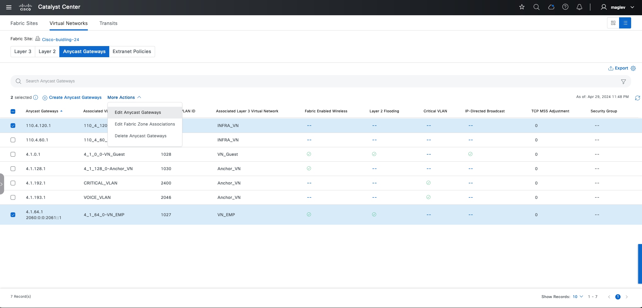
INFRA_VN has an AP pool and an extended node pool, only TCP MSS Adjustment can be changed.
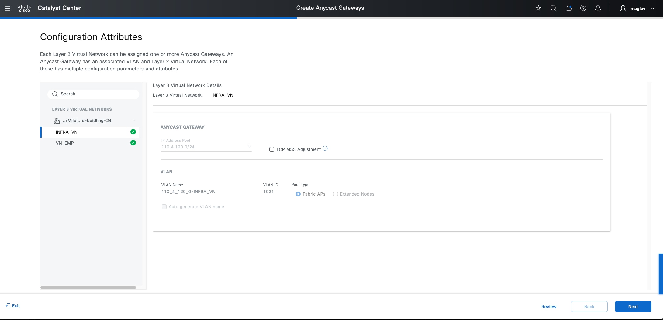
Tech tip: The extended node pool can be changed to an SBEN pool as demonstrated in the Procedure 3: Onboard supplicant-based extended node section.
For the customer VN, VLAN Name, VLAN ID, Critical VLAN cannot be changed.
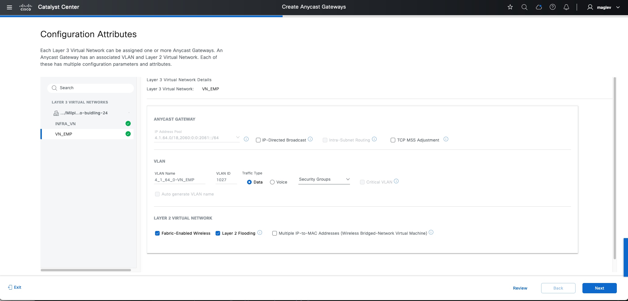
Change site-level authentication
Site-level authentication can be changed directly. The new authentication template configuration will be pushed to all Catalyst Center managed access ports that do not have port assignment configurations.
Step 1. From the top-left corner, click the menu icon and choose Provision > Fabric Sites, click the table view icon in the top right, click the Cisco-building-24 text link then click the Authentication Template tab.
Step 2. Choose a new Authentication Template then click Deploy.
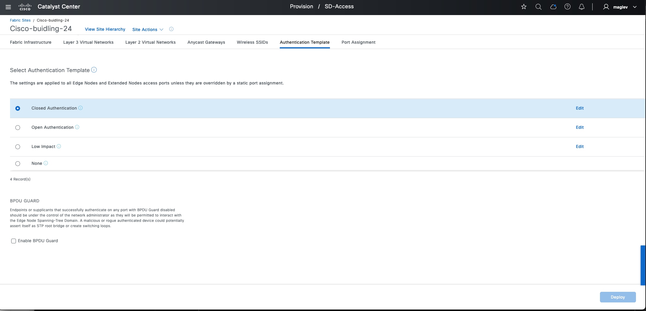
Note: If an SBEN pool is configured, changing Authentication Template from Closed Authentication to another Authentication Template or Enable BPDU Guard is not allowed. Delete all the SBEN nodes, disable the SBEN pool and then change Authentication Template and BPDU Guard settings.
Use banner support
Catalyst Center also provides banner support to help apply day-n changes on the site level. These day-n operations include:
● Migrate IPV4 address pool to IPV4 and IPV6 dual stack pool
● Update DHCP server and DNS IP address
● Add new line card or stack member
Migrate IPV4 address pool to dual stack pool
This example process demonstrates migrating the IPV4 client pool Building-24-Emp to a dual stack pool in Cisco-building-24.
Step 1. From the top-left corner, click the menu icon and choose Design > Networking Setting then click the IP Address Pools tab.
Step 2. Switch from Global to Cisco-building-24. Check the Building 24-Emp check box then choose More Actions > Edit.
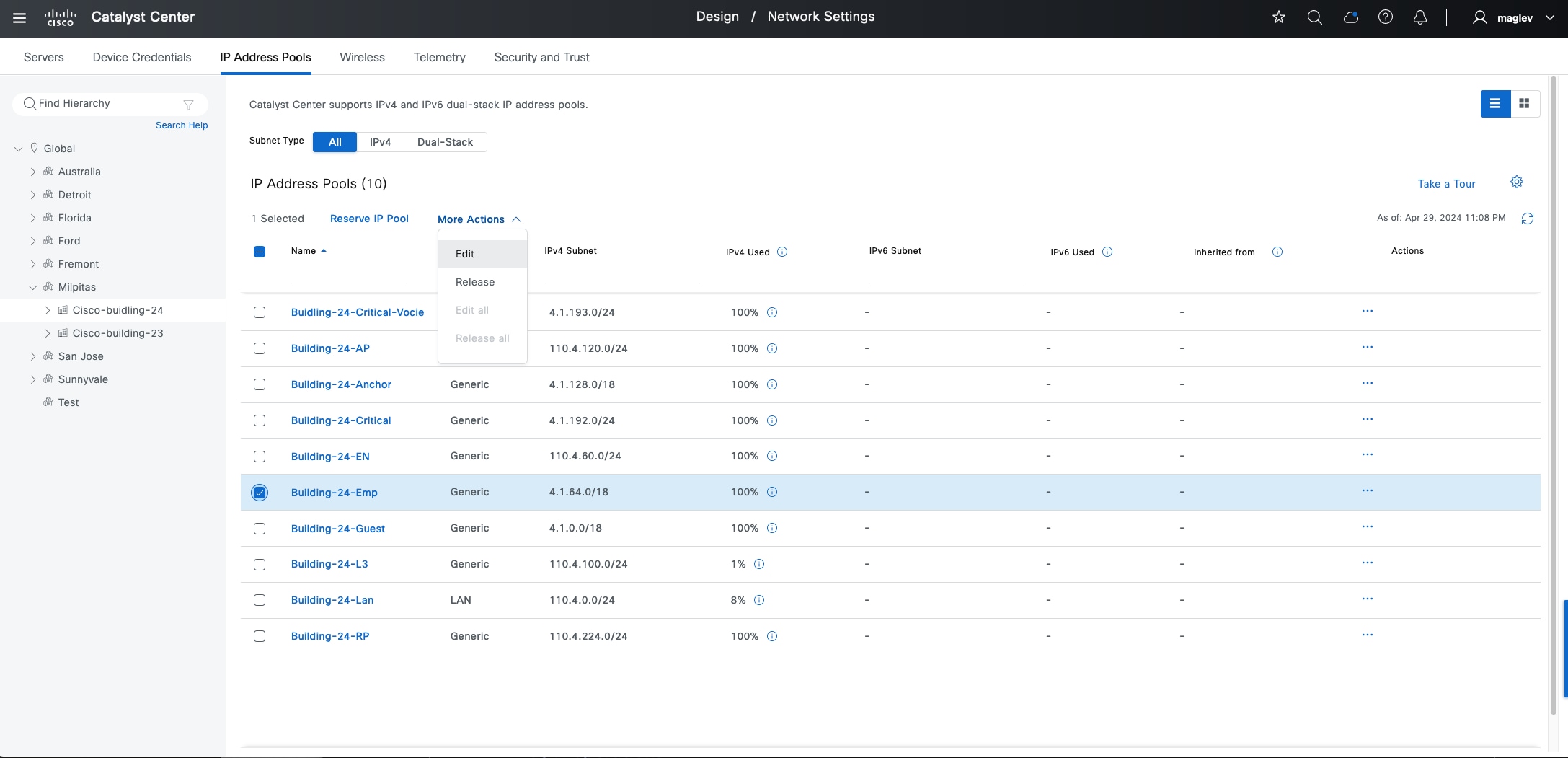
Step 3. Check the IPV6 check box and enter the required information in the Global Pool, Prefix Length, IPv6 subnet, and Gateway fields then click Save.
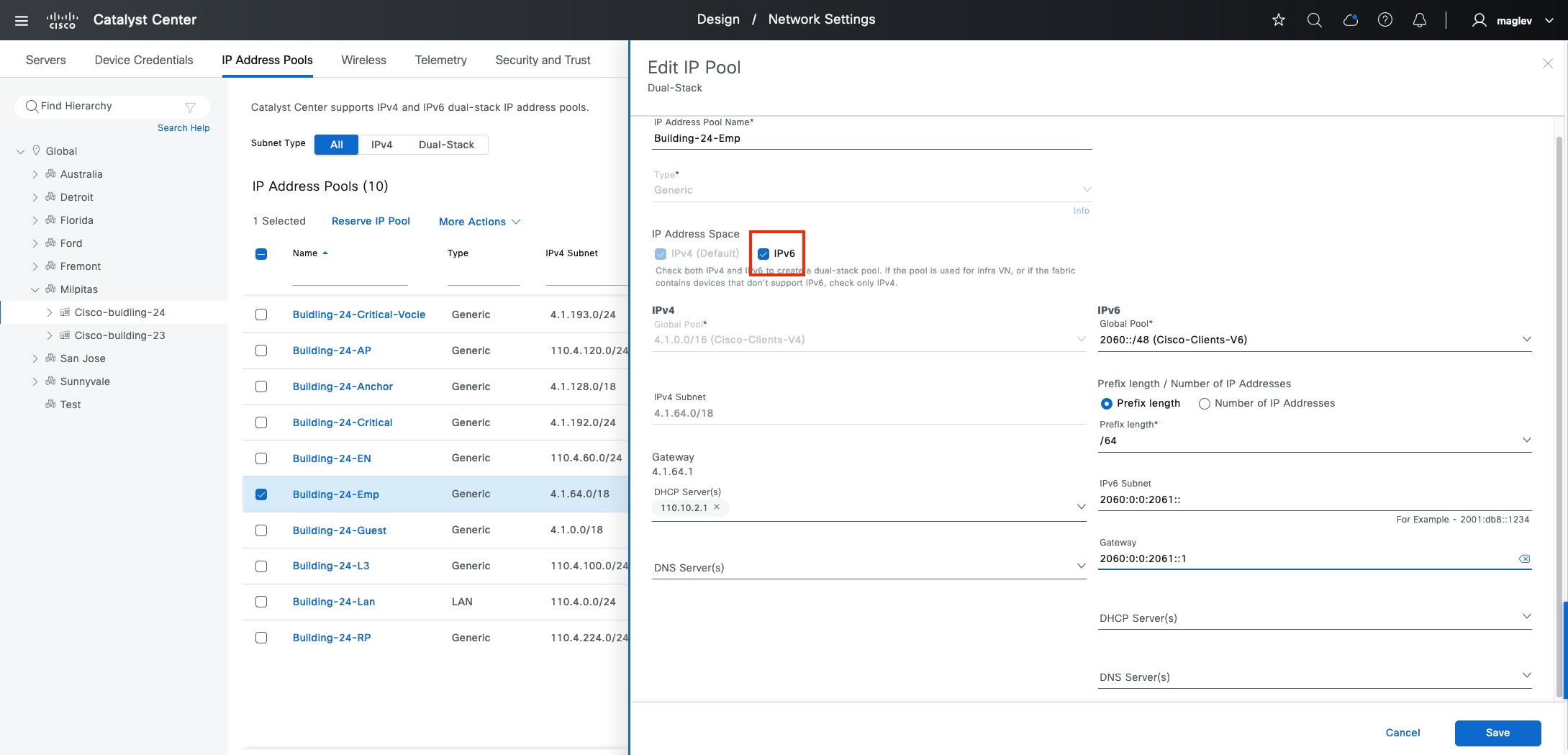
Step 4. From the top-left corner, click the menu icon and choose Provision > Fabric Sites, click the table view icon in the top right, click the Cisco-building-24 text link then click the Fabric Infrastructure tab.
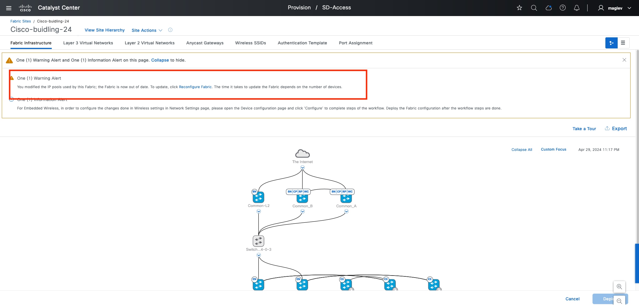
Step 5. Click Reconfigure Fabric in the banner then click Deploy.
Note:
1. When the Reconfigure Fabric banner displays, all fabric operations in this site are blocked.
2. If there is a fabric zone and the IP address pool is used in the zone, the banner appears in both the site and the zone.
Step 6. Click the Anycast Gateway tab. The pool is converted to a dual stack pool.
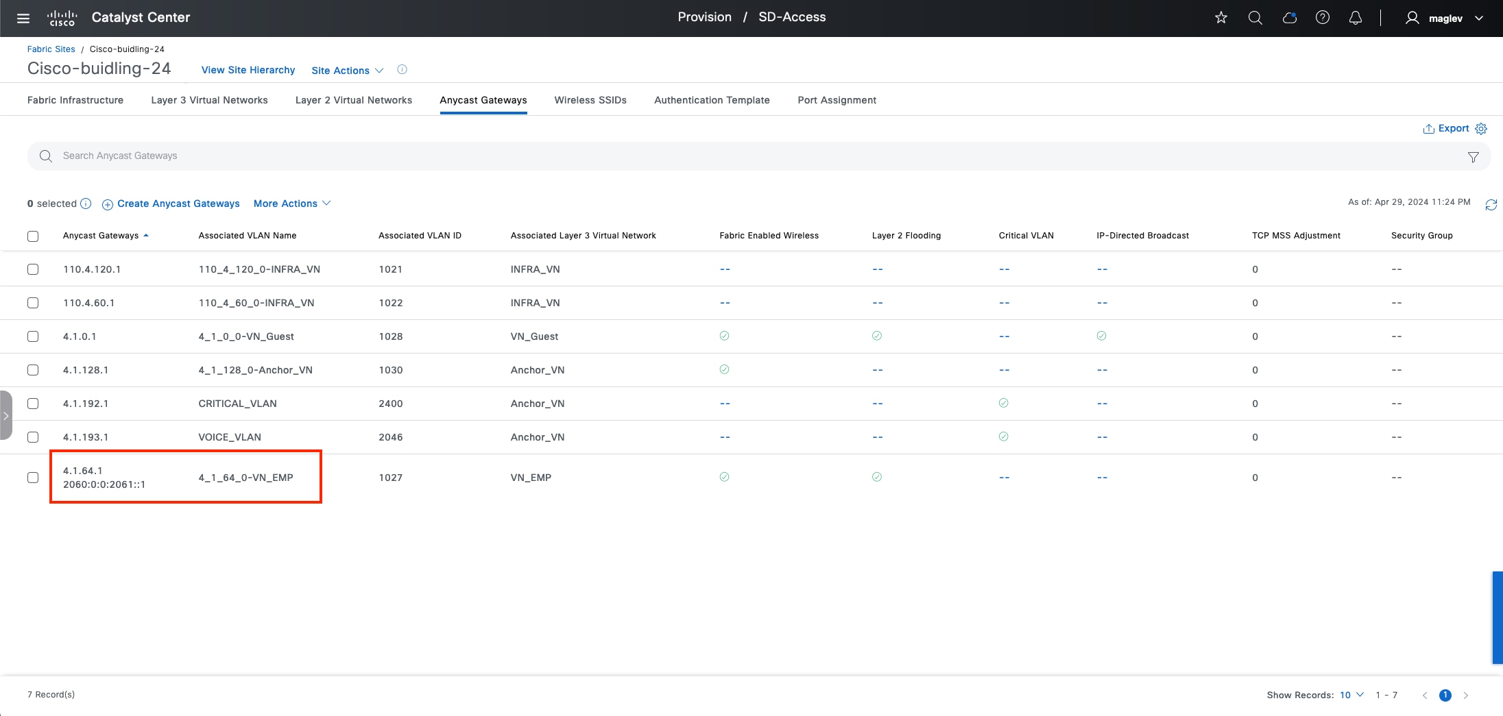
Update DHCP or DNS server in an IP address pool
Updating DHCP or DNS in an IP address pool uses the same reconfigure banner.
Step 1. From the top-left corner, click the menu icon and choose Design > Networking Setting, then click the IP Address Pools tab.
Step 2. Switch from Global to Cisco-building-24. Check the Building 24-Emp check box, choose More Actions > Edit, associate DHCP Server(s) then click Save.
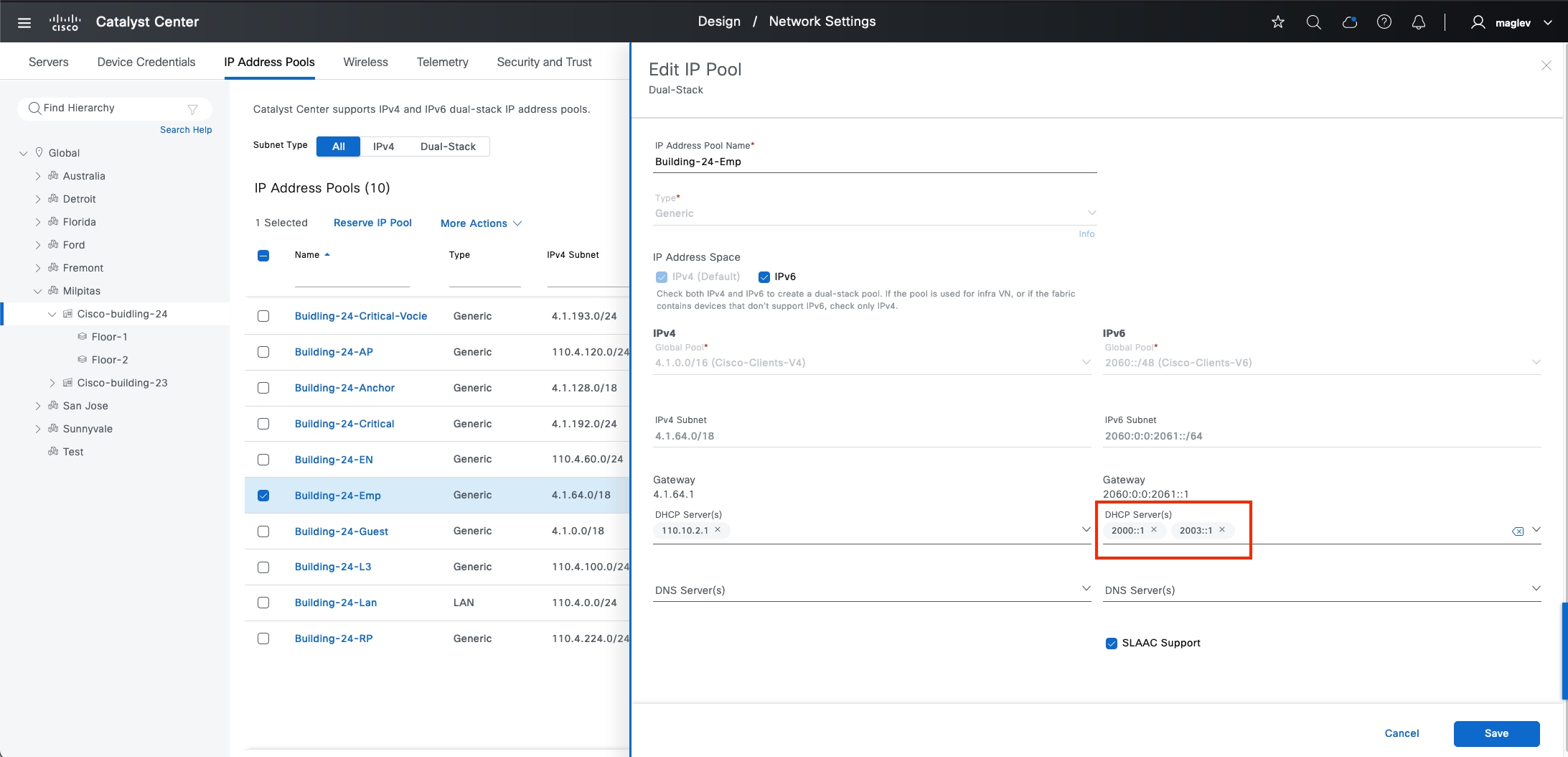
Step 3. From the top-left corner, click the menu icon and choose Provision > Fabric Sites, click the table view icon in the top left, click the Cisco-building-24 text link then click the Fabric Infrastructure tab.
Step 4. Click Reconfigure Fabric in the banner then click Deploy. See Figure 49 for reference.
Add a new line card to the fabric edges
After adding a new line card or new stack member to a fabric edge device or extended nodes, the new line card or stack member does not have the site-level authentication template applied to access ports (If the site-level authentication template setting is anything except None). As shown in Figure 48, apply the banner to configure the authentication template to all the access ports in the new line card or the new stack member.
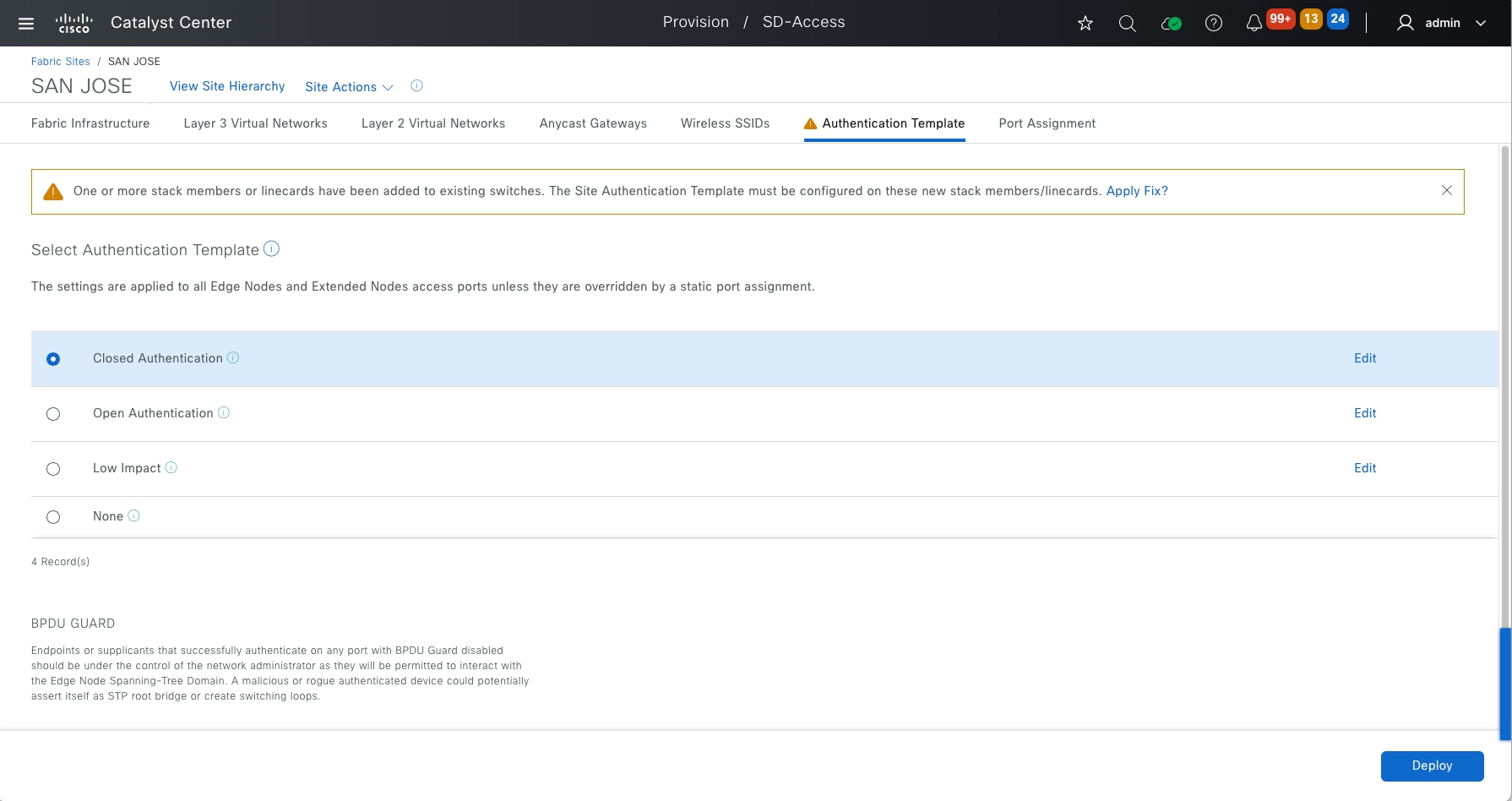
Note: This banner does not block fabric operation.
Use the migration banner in an upgraded cluster
After upgrading a cluster to a new release, there might be new mandatory changes such as critical fixes, behavior changes, and so forth in a Cisco SD-Access network.
Catalyst Center provides a migration banner to apply the changes. It is recommended to apply the changes at the earliest time and in a maintenance window activity.
Starting from 2.3.7.6, applying migration banner is mandatory and network admin has 180 days to apply the banner. All fabric operations will be blocked if the 180 days’ time is expired.
As shown in Figure 49, from the table view of the Fabric Sites tab, a banner informs that there are mandatory updates and that for each of the fabric sites, the Outstanding Updates and Update Grace Period, information is added.
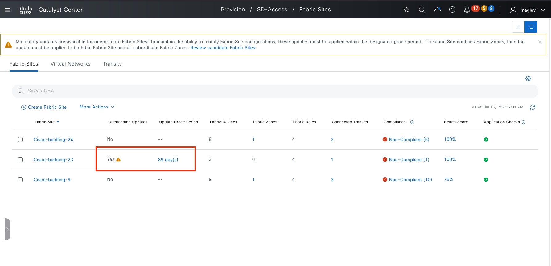
Step 1. To apply the mandatory updates. Click Cisco-building-23 then click OK in the information window.
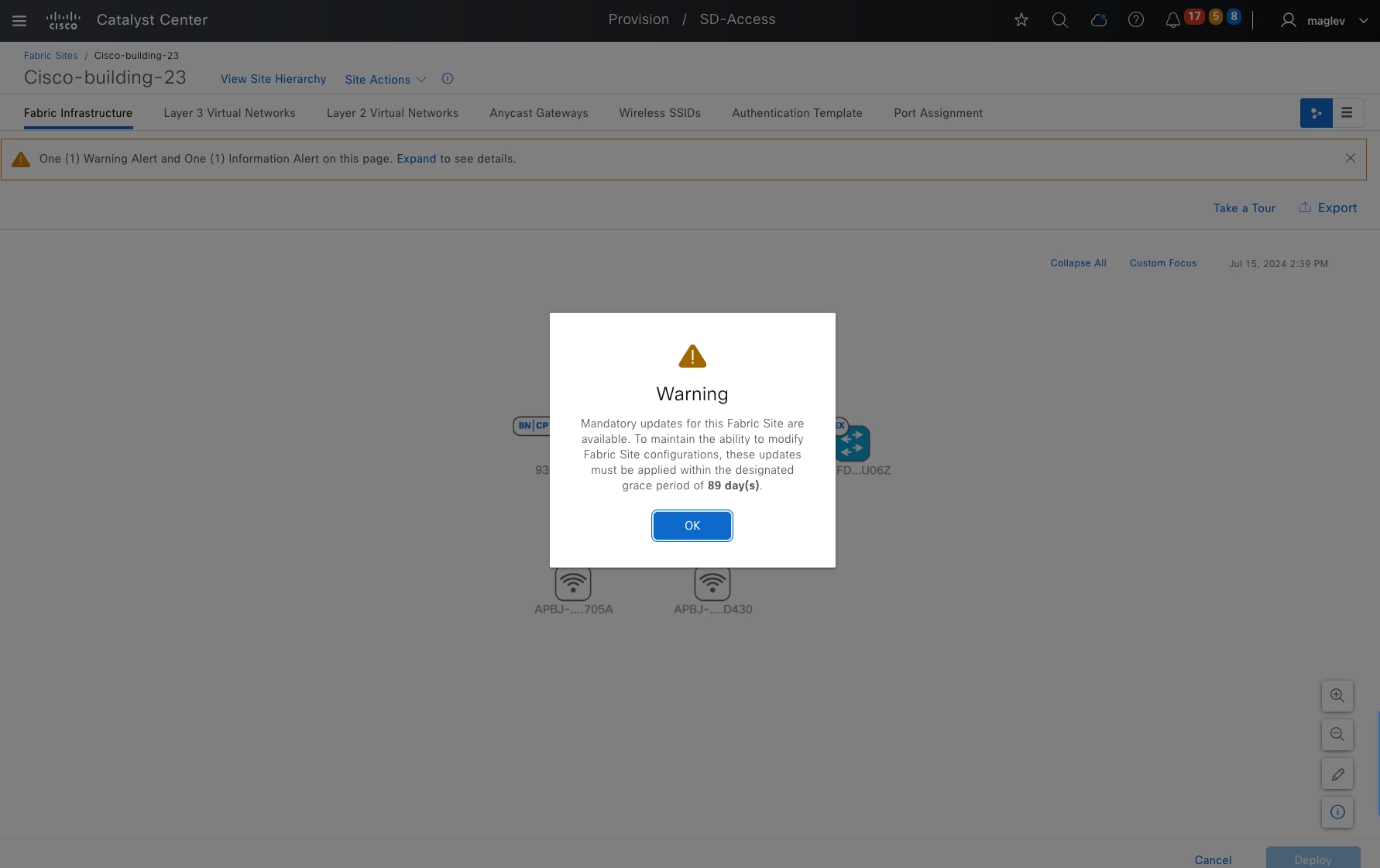
Step 2. Click Expand.
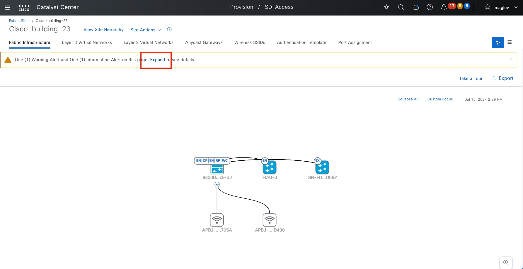
Step 3. Click Review the updates.
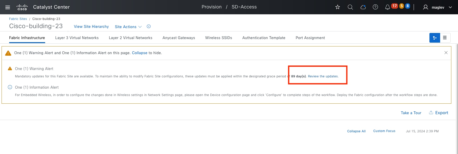
Step 4. In this fabric site, there is only one update, click Apply All to apply the updates.
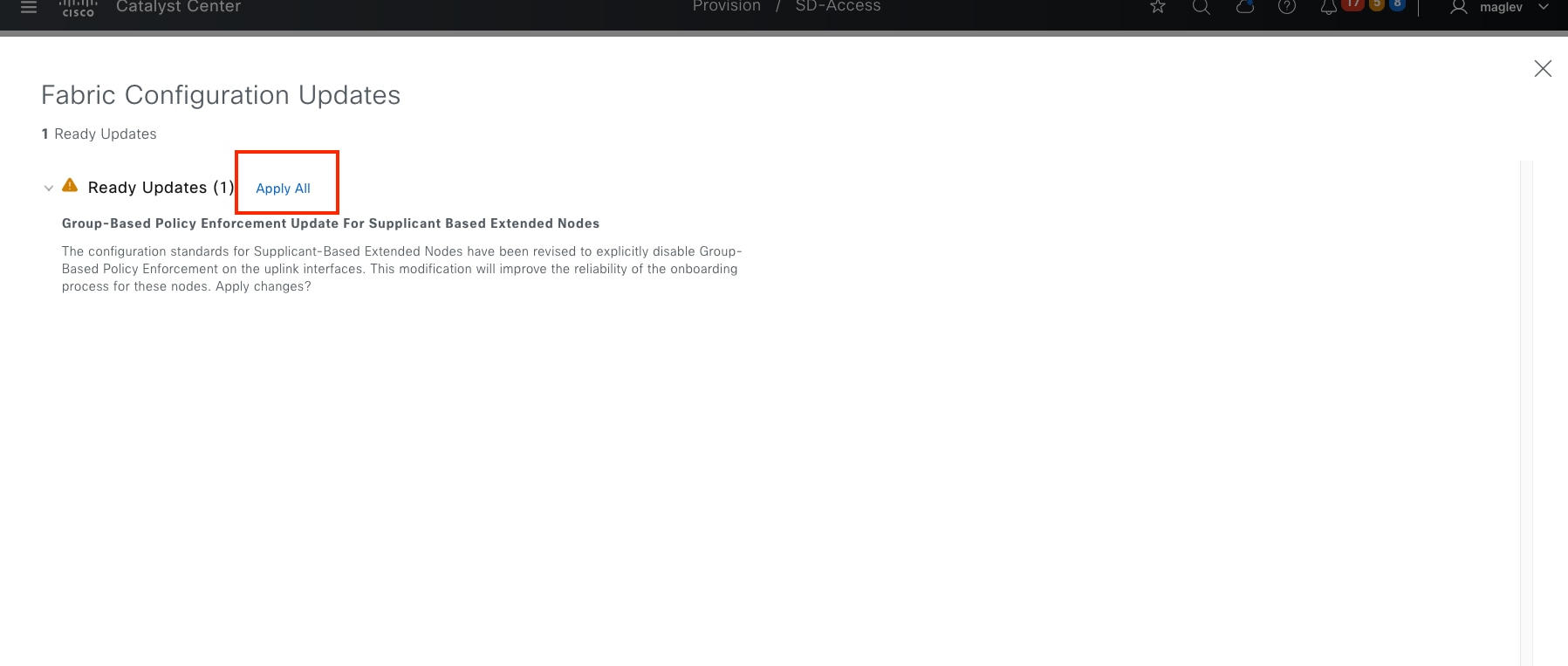
RMA provides a common workflow to replace routers, switches, and APs. In a fabric deployment, the RMA workflow is supported in all fabric devices, except:
● Devices with embedded wireless controllers
● Cisco Wireless Controllers
● Chassis-based Nexus 7700 Series switches
● Switch stacks (SVL stacking)
● Platforms in REP ring
Do these RMA steps on the faulty device through Catalyst Center:
Step 1. Mark the faulty device for replacement.
Step 2. Start the device replacement.
Step 3. Assign the replacement device.
The faulty device and replacement device must have the same PID and the same module. If the faulty device has an uplink network module, the replacement device must have the same uplink network module.
The replacement device can be onboarded in two ways:
● The one-touch method adds the replacement device to Inventory through discovery or inventory import.
● The zero-touch method onboards the replacement device through PnP.
During RMA step 1, mark the faulty device for replacement, a temporary DHCP server configuration will be pushed to one of its neighbor devices, which is managed by Catalyst Center. Interfaces connected to other neighbors are shut down on these neighbors. The replacement device can do Zero Touch onboarding using PnP and obtain an IP from this DHCP server.
The DHCP server configuration will be removed, and interfaces will be restored by Catalyst Center automatically after the RMA process completes.
If a faulty AP or an extended node requires an RMA, there is no need for a temporary DHCP server configuration. The replacement AP and extended node receives an IP address from the same DHCP server that is configured for the AP pool and extended node pool. They are then onboarded through the PnP process, which allows for zero-touch onboarding.
If the replacement device is added through discovery or imported to Inventory directly, make sure its software version is the same as the faulty device. If it is onboarded through PnP and the faulty device is running a golden image, Catalyst Center upgrades the replacement device to the golden image using SWIM.
This section is focused on the RMA procedure using zero touch. RMA of a fabric edge device, and RMA of colocated border and control plane device are demonstrated with the topology shown in figure 53. The fabric AP RMA procedure is the same as a nonfabric AP RMA, see the Wireless Automation with Cisco Catalyst Center (CVD) guide.
RMA a fabric edge with replacement device zero touch onboarding
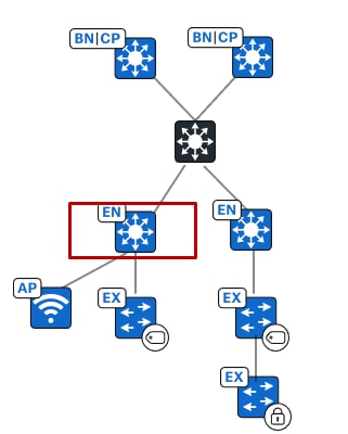
Step 1. From the top-left corner, click the menu icon and choose Provision > Inventory, click the list view icon in the top right.
Step 2. Change Focus to Device Replacement.
Step 3. Check the Switch-110-4-0-9 check box then choose Actions > Device Replacement > Mark for Replacement.
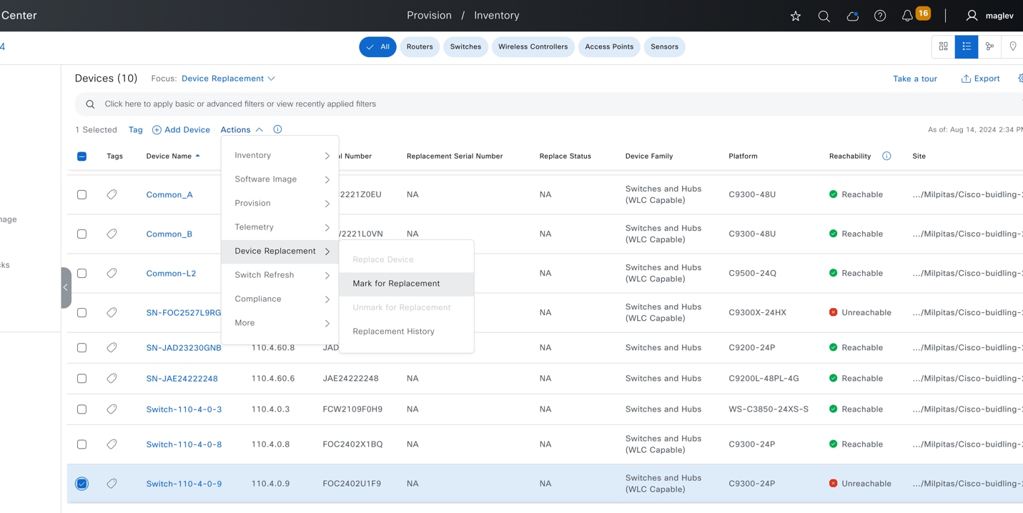
Note:
1. If the faulty device is an extended node, AP, or nonfabric device, network readiness is skipped and the Replace status changes to Ready For Replacement.
2. If a neighbor device is another fabric edge, and the faulty device is not an extended node nor AP, in addition to adding the DHCP server configuration, Catalyst Center also removes PnP VLAN from the neighbor device (PnP VLAN configures when an extended node pool is active and used for extended node onboarding).
3. Starting from Catalyst Center 2.3.7.9, to mark the faulty device for replacement, the faulty device must be Unreachable.
Network readiness is triggered after the Mark for Replacement operation completes. The DHCP server configuration is pushed to a neighbor device. When the configuration is successful, the Replace Status changes from NA to Ready For Replacement.
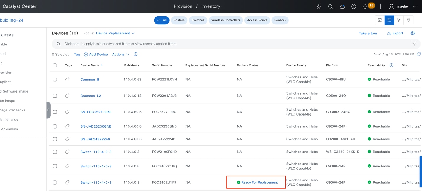
Step 4. Click Ready For Replacement. A message displays explaining that the DHCP configuration is pushed to the neighbor 110.4.0.3.
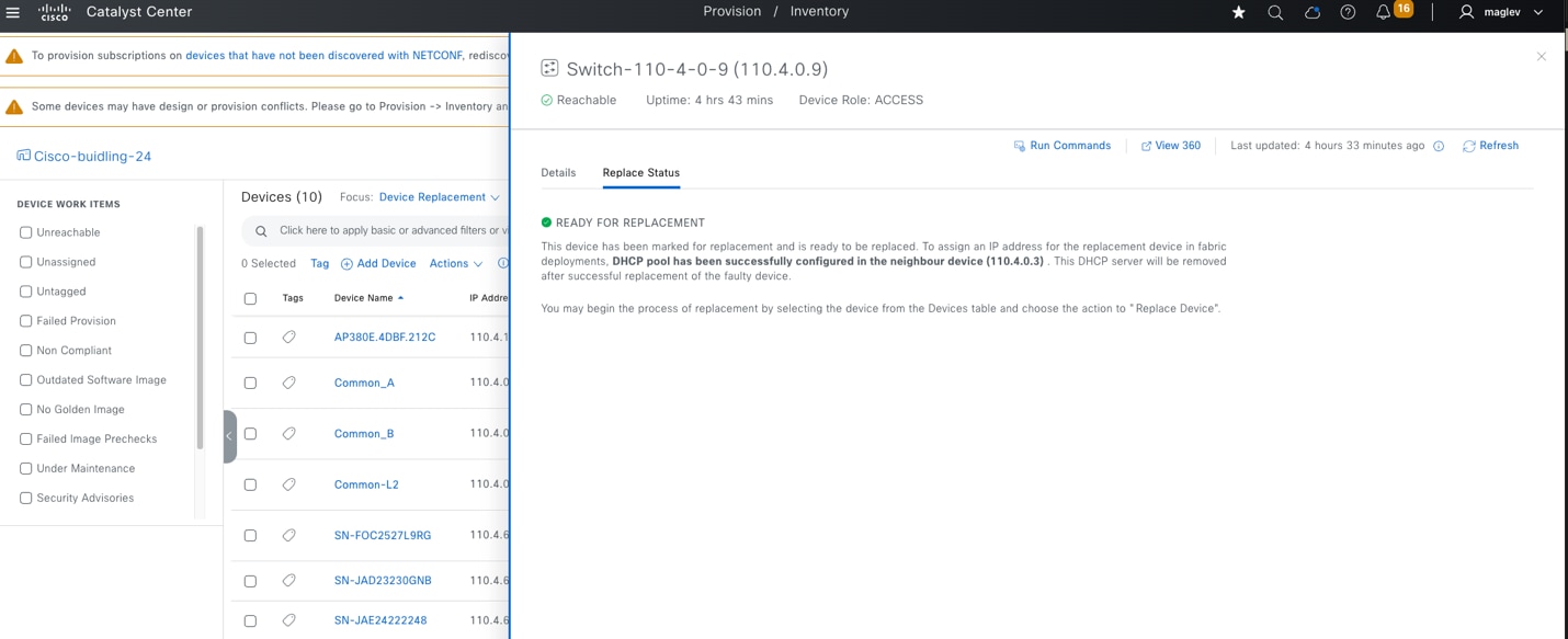
Step 5. Review console output from the neighbor device.
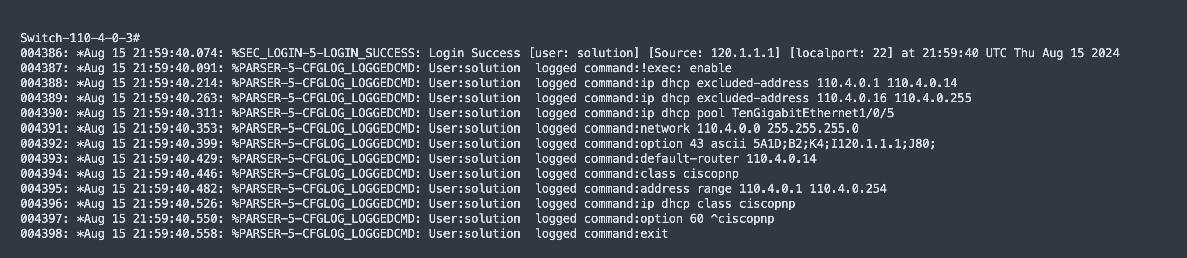
Step 6. Connect the replacement switch to the same port on the intermediate switch. The replacement device starts PnP onboarding.
Step 7. From the top-left corner, click the menu icon and choose Provision > Plug and Play, then click the Unclaimed tab.
Step 8. After the new device appears and the onboarding status shows Device is ready to be claimed, switch back to the Inventory window to start RMA. From the top-left corner, click the menu icon and choose Provision > Inventory, click the list view icon in the top right then change Focus to Device Replacement.
Step 9. Check the Switch-110-4-0-9 check box then choose Actions > Device Replacement > Replace Device.
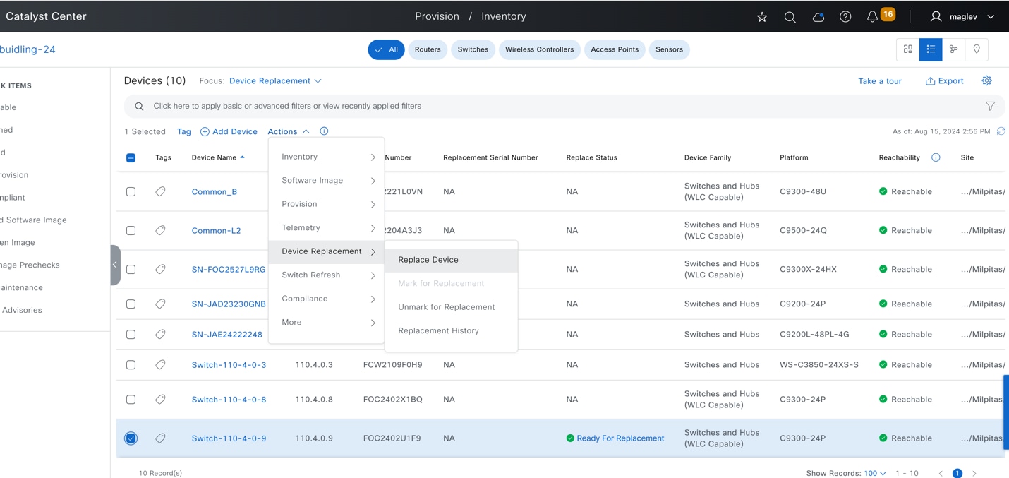
Step 10. In the workflow to do zero touch onboarding, click the Plug and Play tab. The replacement device shows up after it connects with Catalyst Center.
Step 11. Choose the device then click Next.
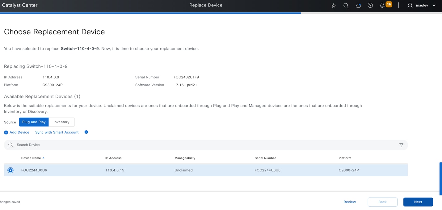
Step 12. Review the summary of the task then click Next.
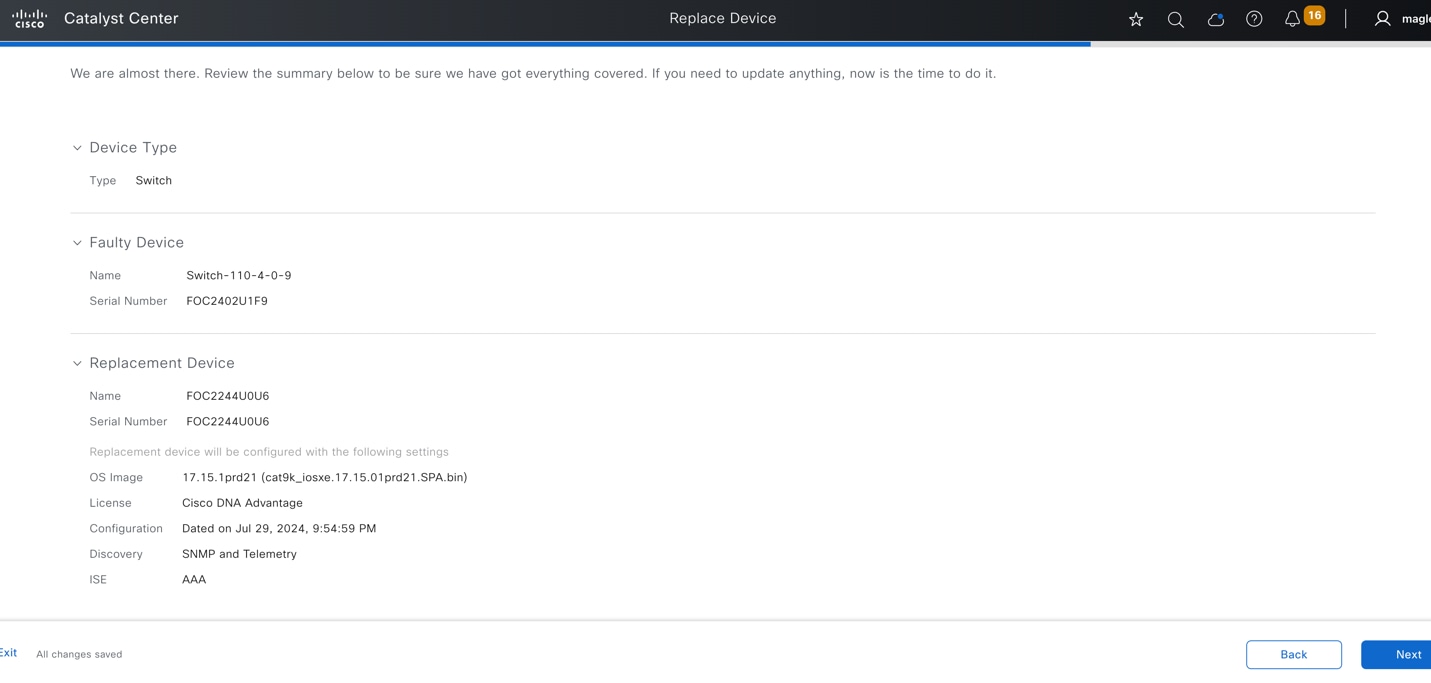
Step 13. Configuration preview is supported. Review the configuration to be pushed to the replacement device then click Deploy to push the configuration.
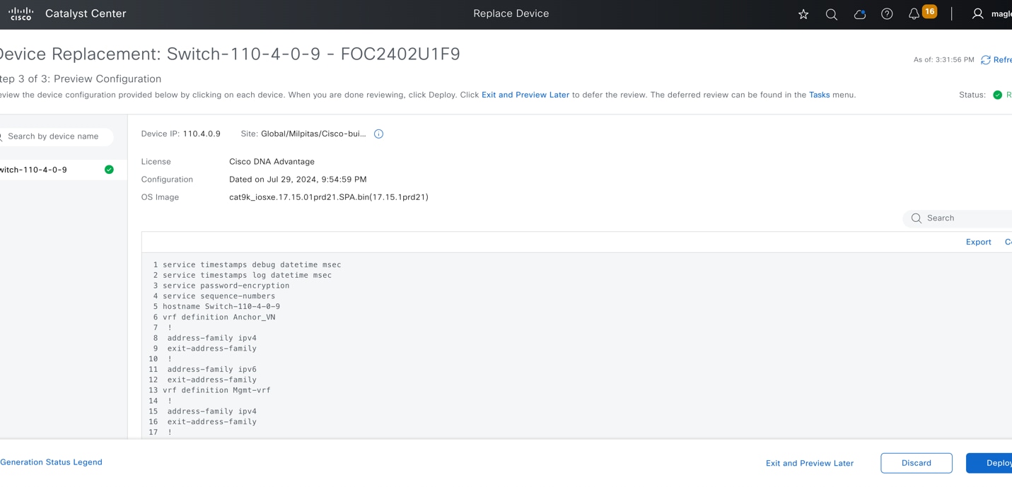
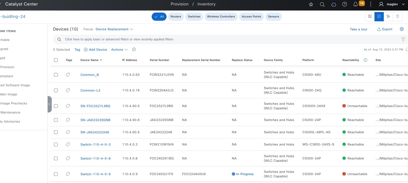
Step 14. To monitor the RMA progress, click In-Progress and review the task status in the slide-in pane.
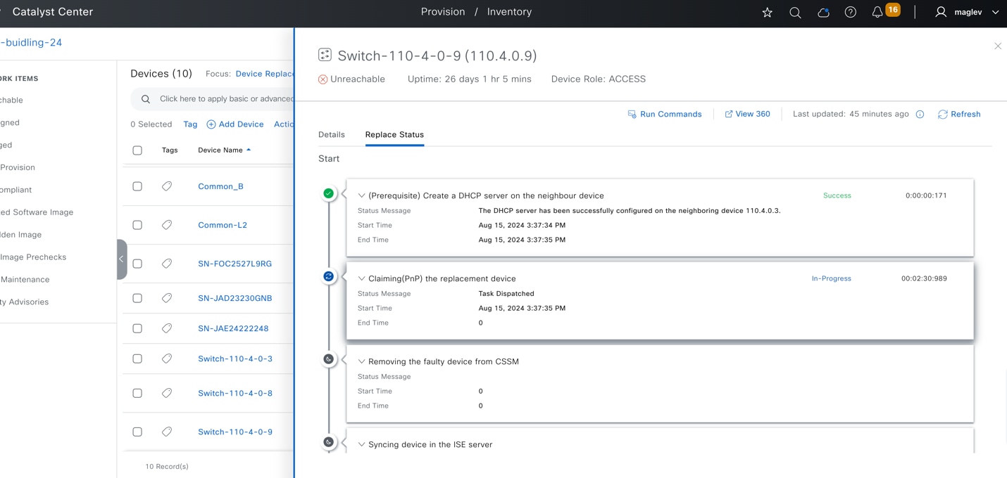
Step 15. If the replacement device is not running the same image as the faulty device, Catalyst Center upgrades the replacement device to the golden image. Make sure the image in the faulty device is marked as Golden.
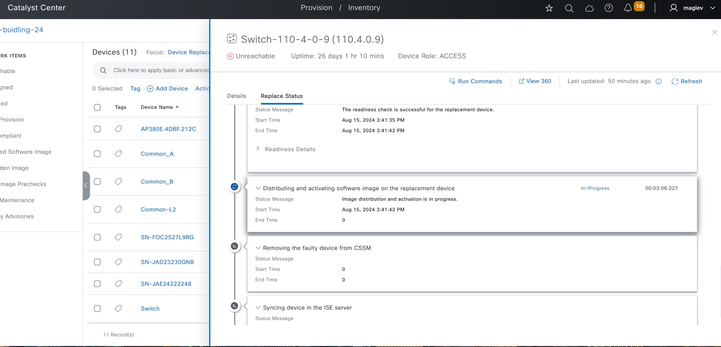
Step 16. Wait until the RMA completes. The Replace Status changes to NA.
Step 17. Choose Actions > Device Replacement > Replacement History.
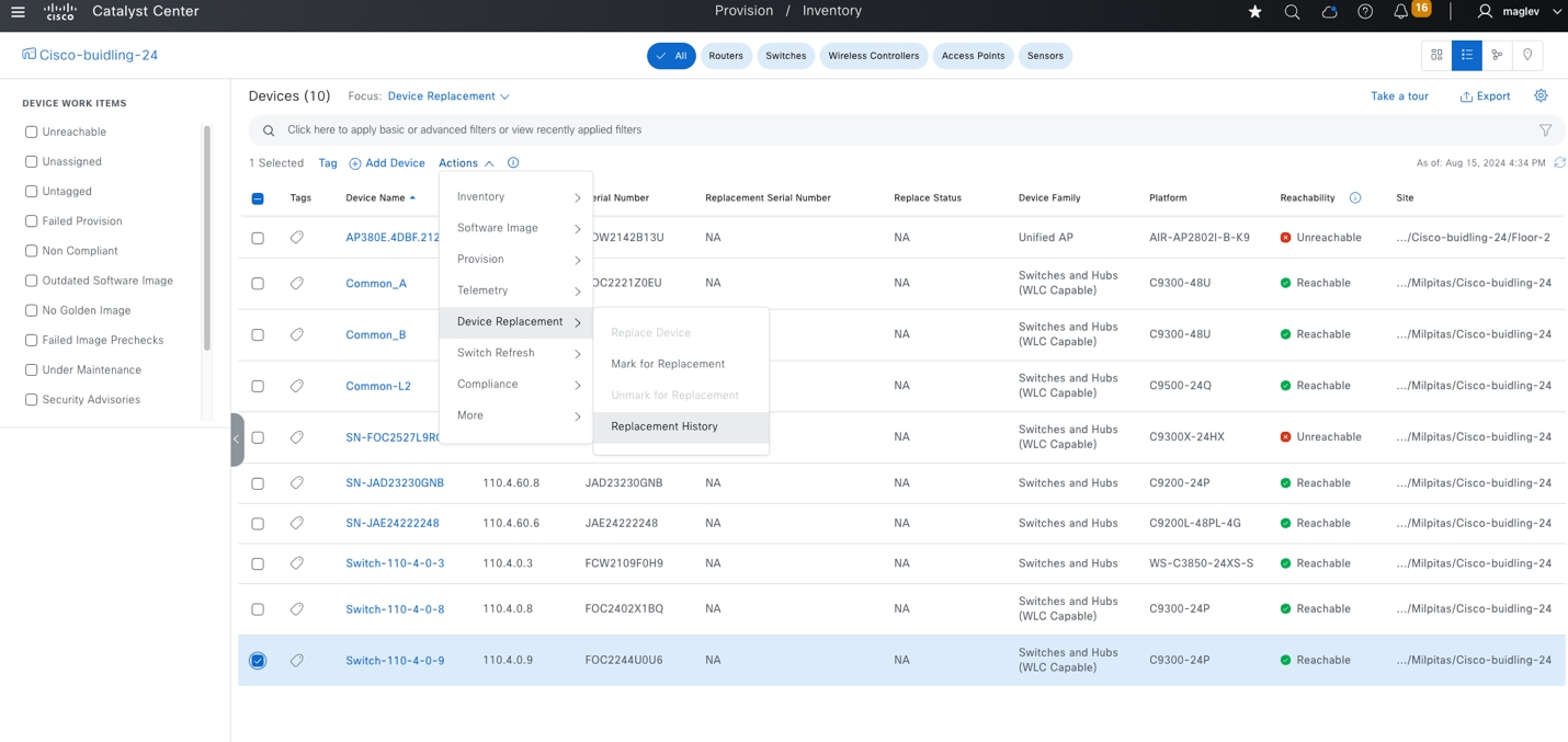
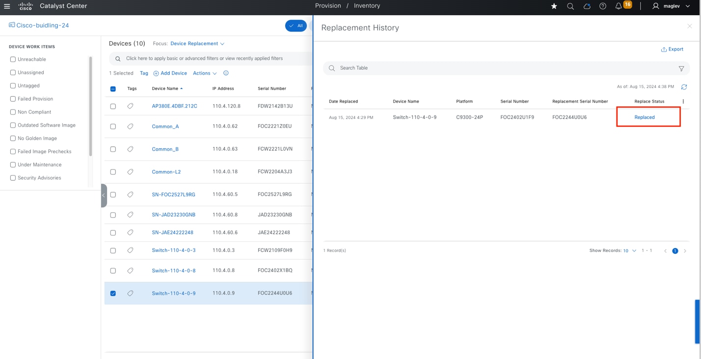
Step 18. Confirm on the neighbor device that the DHCP server configuration is deleted.
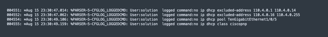
Step 19. Resume other connections, such as to all the extended nodes, to all the APs, and to clients using the same ports as the faulty device.
RMA a colocated border and control plane device with zero touch onboarding
The RMA for a colocated border with a control plane is similar to an RMA of a fabric edge device. The faulty fabric border with control plane (Common_B) is connected to an intermediate switch (Switch-110-4-0-3), to Common_A, and to a peer device.
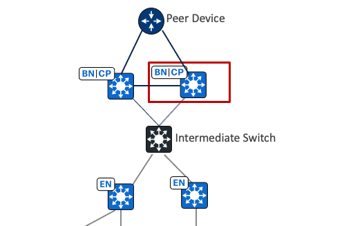
Step 1. From the top-left corner, click the menu icon and choose Provision > Inventory, click the list view icon in the top right.
Step 2. Change Focus to Device Replacement.
Step 3. Check the Common_B check box then choose Actions > Device Replacement > Mark for Replacement.
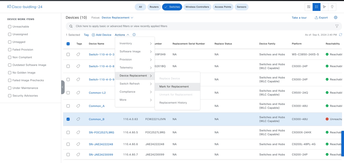
Network readiness pushes the DHCP server configuration to an uplink neighbor device.
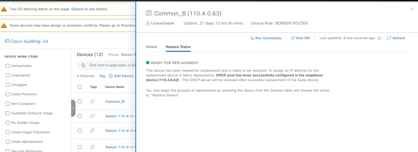
Step 4. Confirm on the Common_A device.
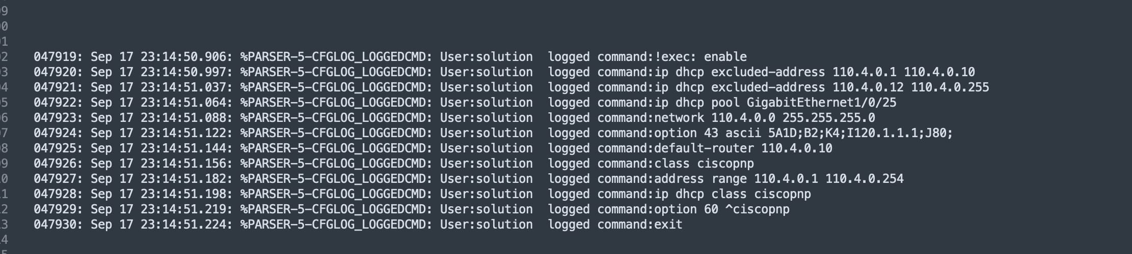
Step 5. Connect the replacement switch to the same ports on Common_A, to the peer device, and to the intermediate switch. The new switch starts PnP onboarding.
Step 6. Monitor the Plug and Play window.
Step 7. From the top-left corner, click the menu icon and choose Provision > Plug and Play, then click Unclaimed.
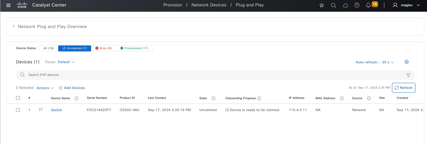
Step 8. After the new device appears and the onboarding status shows Device is ready to be claimed, switch back to start the RMA. From the top-left corner, click the menu icon and choose Provision > Inventory, click the list view icon in the top right then change Focus to Device Replacement.
Step 9. Check the Common_B check box then choose Actions > Device Replacement > Replace Device.
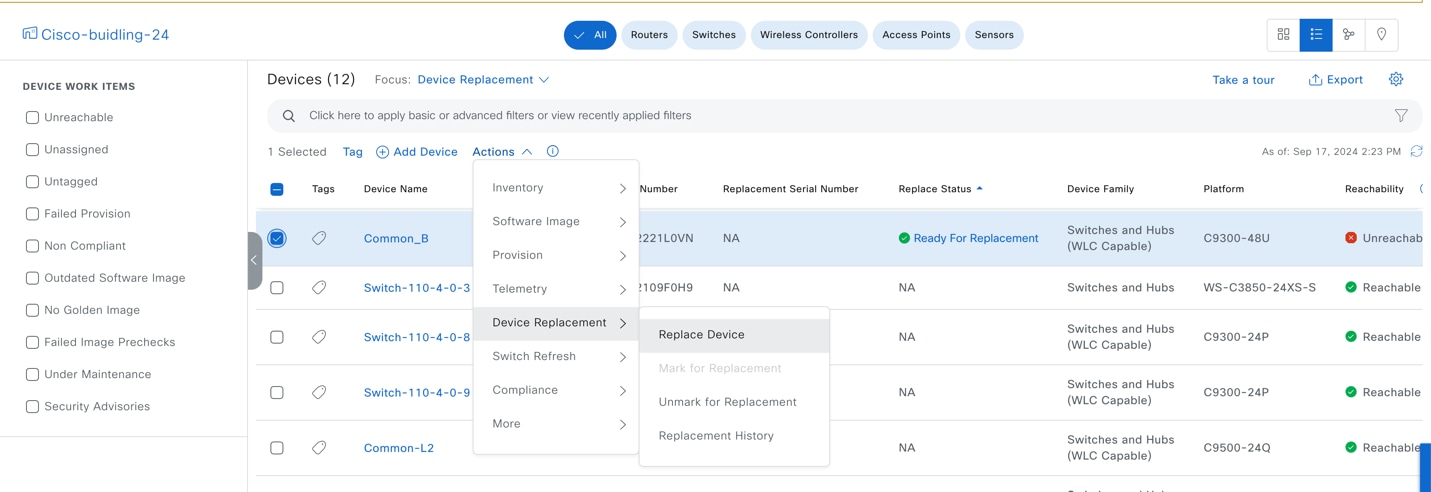
Step 10. In the zero-touch onboarding workflow, click the Plug and Play tab, click the replacement device radio button then click Next.
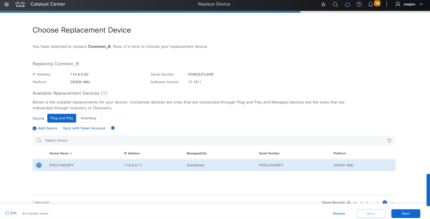
Step 11. Review the summary of the task then click Next.
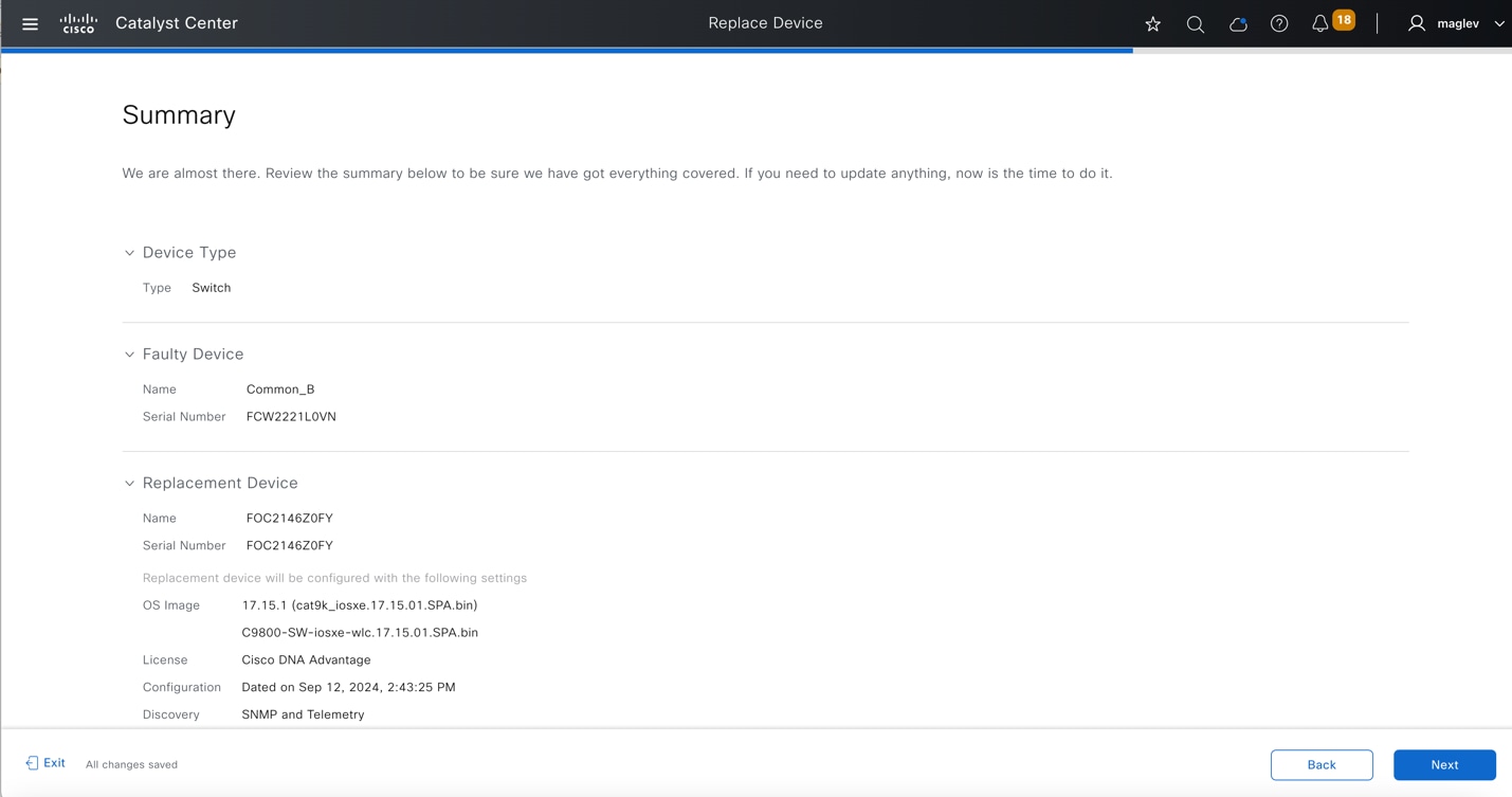
Step 12. Review the configuration to be pushed to the replacement device then click Deploy to push the configuration.
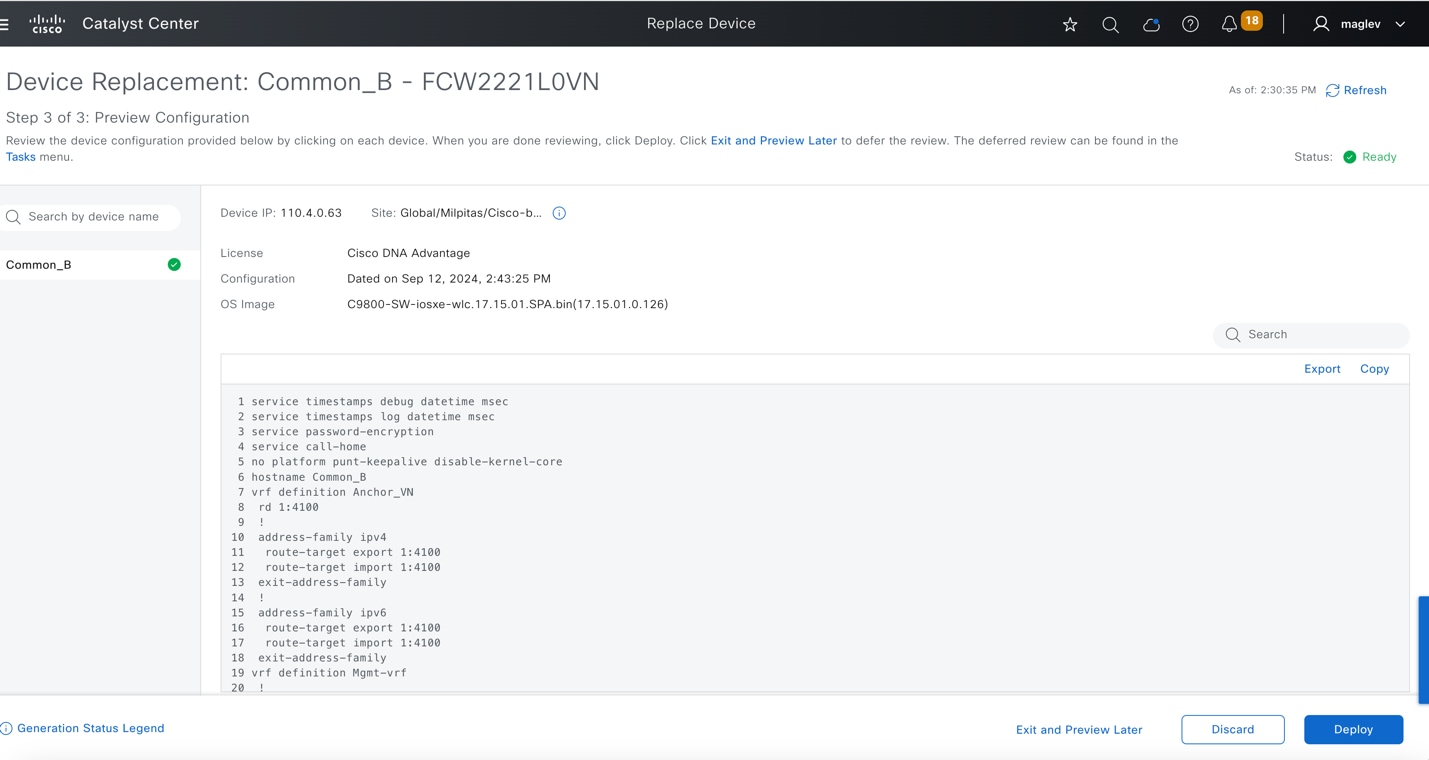
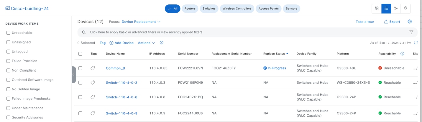
Step 13. To monitor the RMA progress, click In-Progress and review the task status in the slide in pane.
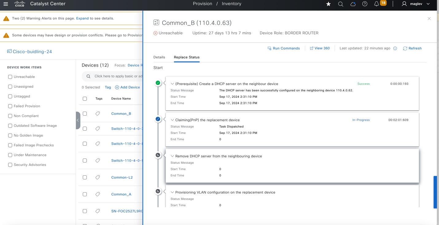
Step 14. If the replacement device is not running the same image as the faulty device, Catalyst Center upgrades the replacement device to the golden image. Make sure the image in the faulty device is marked as Golden.
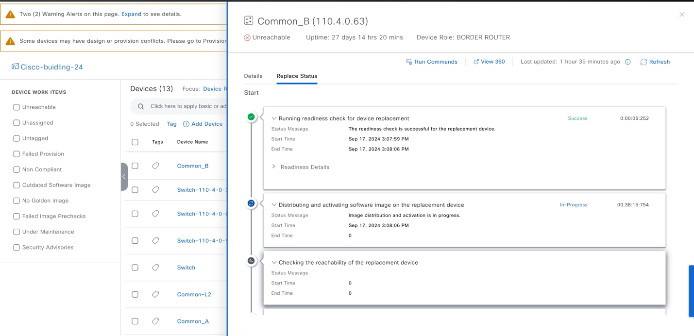
Step 15. Wait until the RMA completes. The Replace Status changes back to NA. Click Actions > Replacement History.
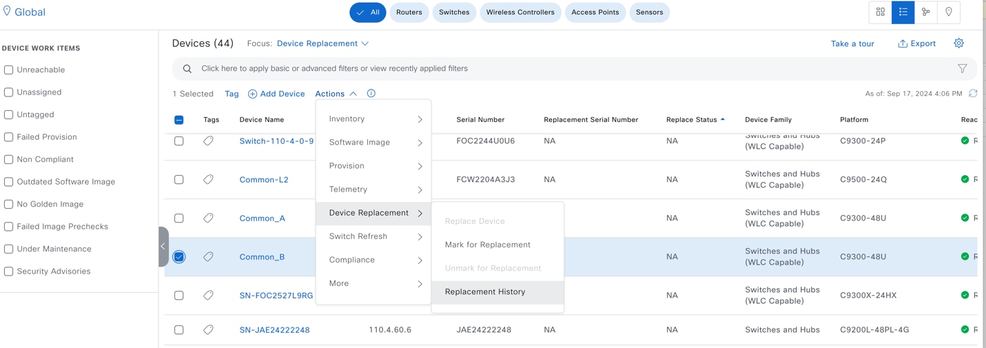
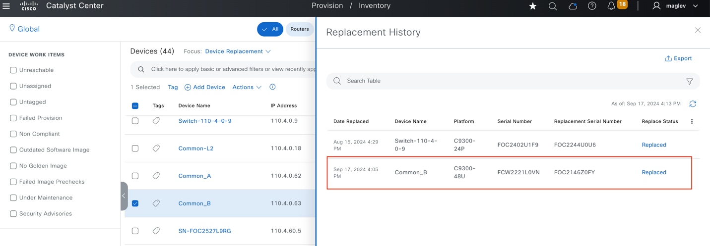
Step 16. Confirm on a Common_A device that the DHCP configuration is deleted.
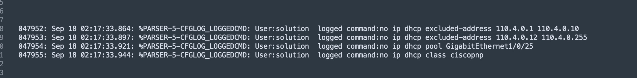
Step 17. Resume other physical connections if any.
Tech tip: When doing an RMA:
1. Disconnect the faulty device and wait for the device to be shown as unreachable in Inventory. Then mark the device for replacement.
2. If the replacement device is powered on, do not connect a replacement device to upstream devices before marking the faulty device for replacement.
3. Before the replacement device completes PnP onboarding, do not connect downstream devices such as extended nodes to it
4. If the faulty device is not an extended node nor AP, make sure at least one of the upstream devices is managed by Catalyst Center to do a zero touch RMA.
5. In the zero touch RMA workflow, if the faulty device has software subpackages, make sure the replacement device is running ‘install’ mode not ‘bundle’ mode.
Tear down a fabric site
This section demonstrates the process to tear down a fabric site:
1. Delete all the fabric devices from the fabric site.
2. Disable the fabric zone.
3. Delete the fabric site.
Deleting devices from Catalyst Center involves disabling fabric roles from fabric sites and deleting devices from the inventory.
Procedure 1. A. Deleting fabric edges or extended nodes, policy extended nodes, or SBEN from the fabric
Part 1: Deleting devices that have an access role, such as extended nodes and fabric edges requiring port assignment clean up.
Step 1. From the top-left corner, click the menu icon and choose Provision > Fabric Sites, click the table view icon in the top right, click the Cisco-building-23 text link then click the Port Assignment tab.
Step 2. Check all the physical ports check boxes (except Port Channel) that have a customized Port Assignment configuration.
Step 3. Choose More Actions > Clear Port Assignment.
Step 4. Click Deploy All and proceed with the deployment.
Step 5. If Port Channel is configured, click Port Channel and choose More Actions > Delete Port‑Channels and proceed with the deployment.
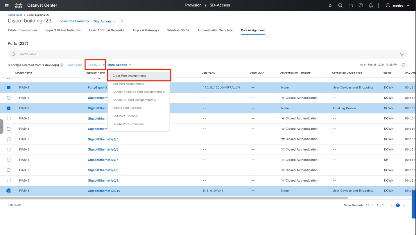
Part 2: After cleaning up the port assignments, disable fabric roles from the fabric site.
Step 1. Navigate to the Fabric Infrastructure window and click the target device.
Step 2. Click Remove from Fabric in the right pane then proceed to deployment.
Procedure 1. B. Deleting fabric border nodes, control plane nodes, and wireless controllers from the fabric site
Step 1. Navigate to the Fabric Infrastructure window then click the target device.
Step 2. Click Remove from Fabric in the right pane then proceed to deployment.
Note: At least one control plane node is required in a fabric site. You cannot delete all the control plane nodes if the fabric site still has devices enabled with other fabric roles. Delete devices with no control plane role first.
Tech tip: If devices are unreachable, the task of cleaning up port assignments and deleting devices from the fabric report as Fail, but the fabric roles of these devices are removed. Deletion from Inventory is allowed.
Procedure 2. Delete devices from inventory
Step 1. From the top-left corner, click the menu icon and choose Provision > Inventory.
Step 2. Locate and check the target device check box.
Step 3. Choose Actions > Inventory > Delete Device and proceed with the deletion workflow.
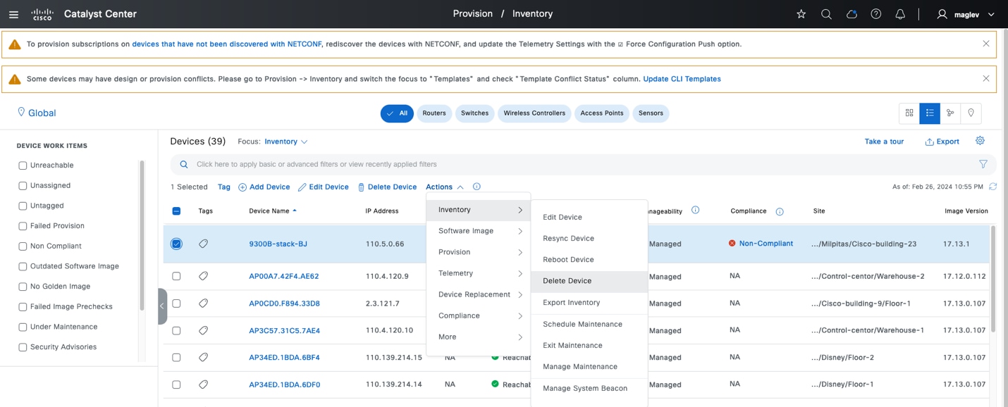
When deleting extended nodes, policy extended nodes, or SBEN, after deleting it from the inventory, clean up the port configuration on their uplink devices. For example:
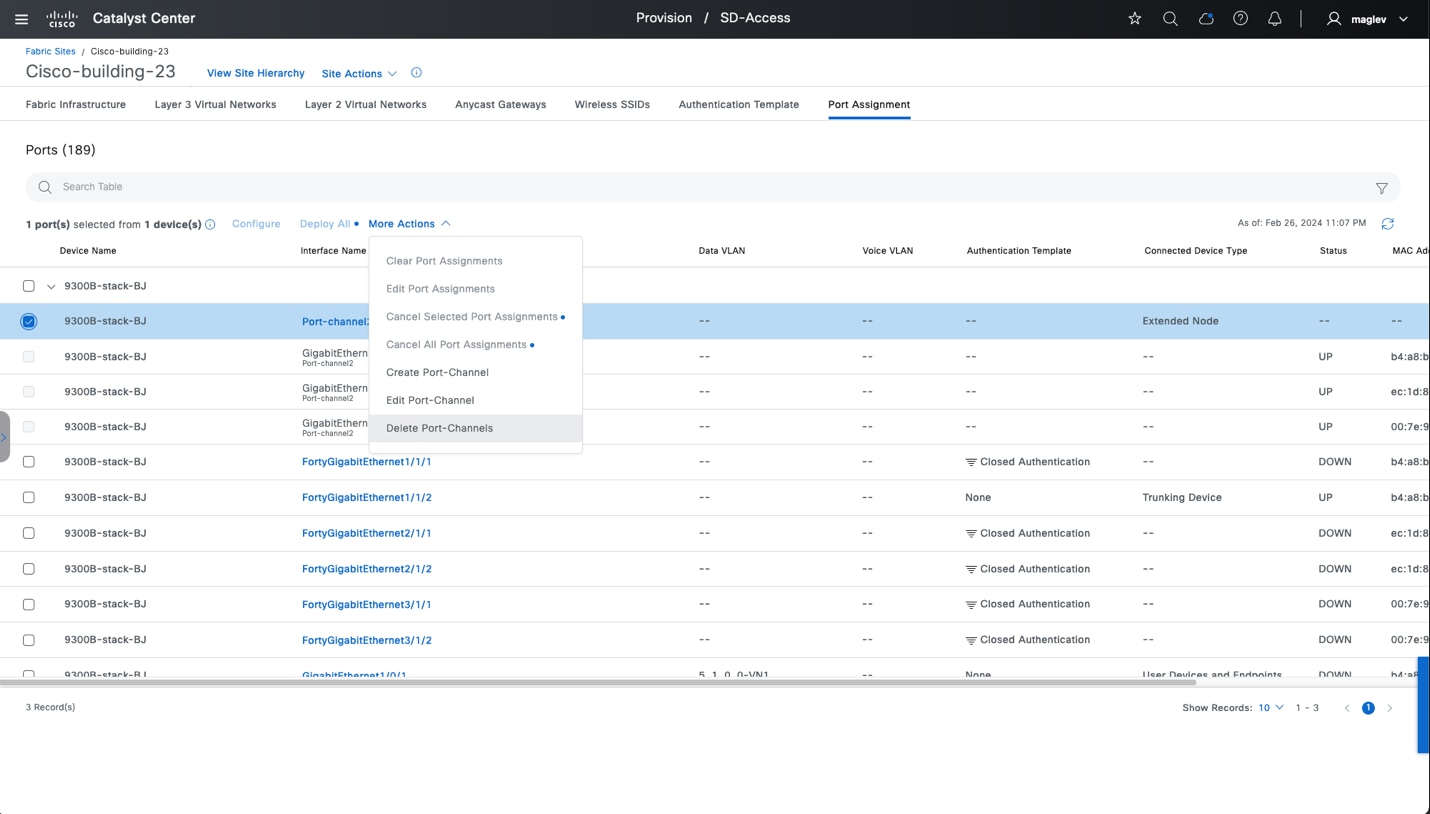
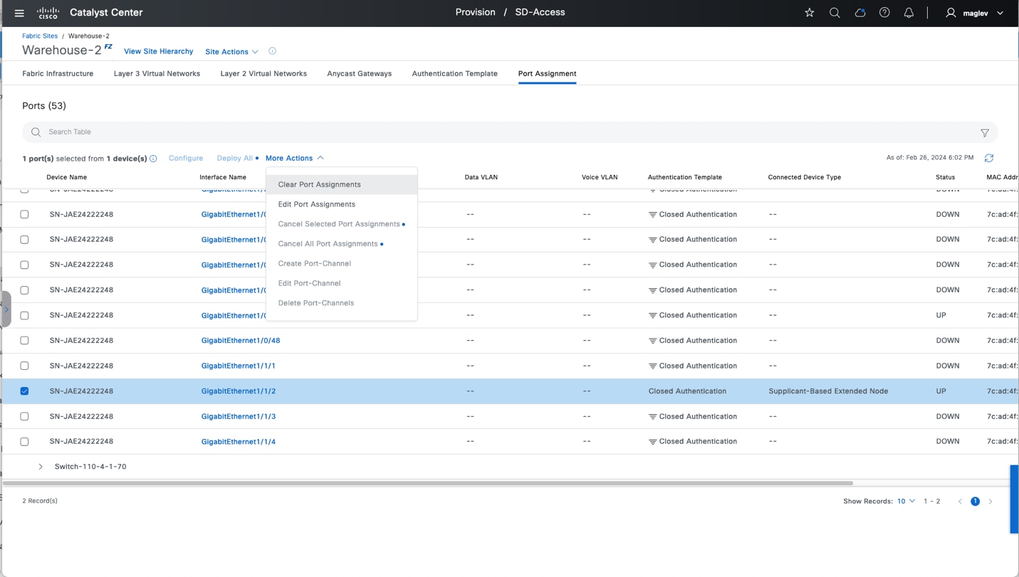
Anycast gateways can be associated to a fabric site then added to a fabric zone and inherited site. To delete anycast gateways from a fabric site, the anycast gateways must first be deleted from the fabric zone and all inherited sites.
Anycast gateway 4.1.0.1 is configured in Anchored VN GUEST of the Control-center and added to the fabric zone Floor-1 and inherited site Cisco-building-9.
Follow Procedure 1 to delete anycast gateway 4.1.0.1 from the fabric zone, inherited site, and control‑center.
Procedure 1. Delete an anycast gateway from a fabric zone
An anycast gateway in a fabric zone can be deleted on either a fabric zone level or a fabric site level.
Method 1: Delete 4.1.0.1 from Floor-1 on the zone level.
Step 1. From the top-left corner, click the menu icon and choose Provision > Fabric Sites > Control‑center, then choose View Site Hierarchy > Floor-1.
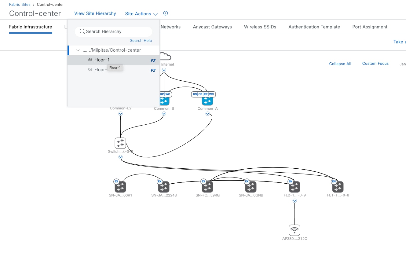
Step 2. Click the Anycast Gateways tab, check the 4.1.0.1 check box, then choose More Actions > Delete Anycast Gateways.
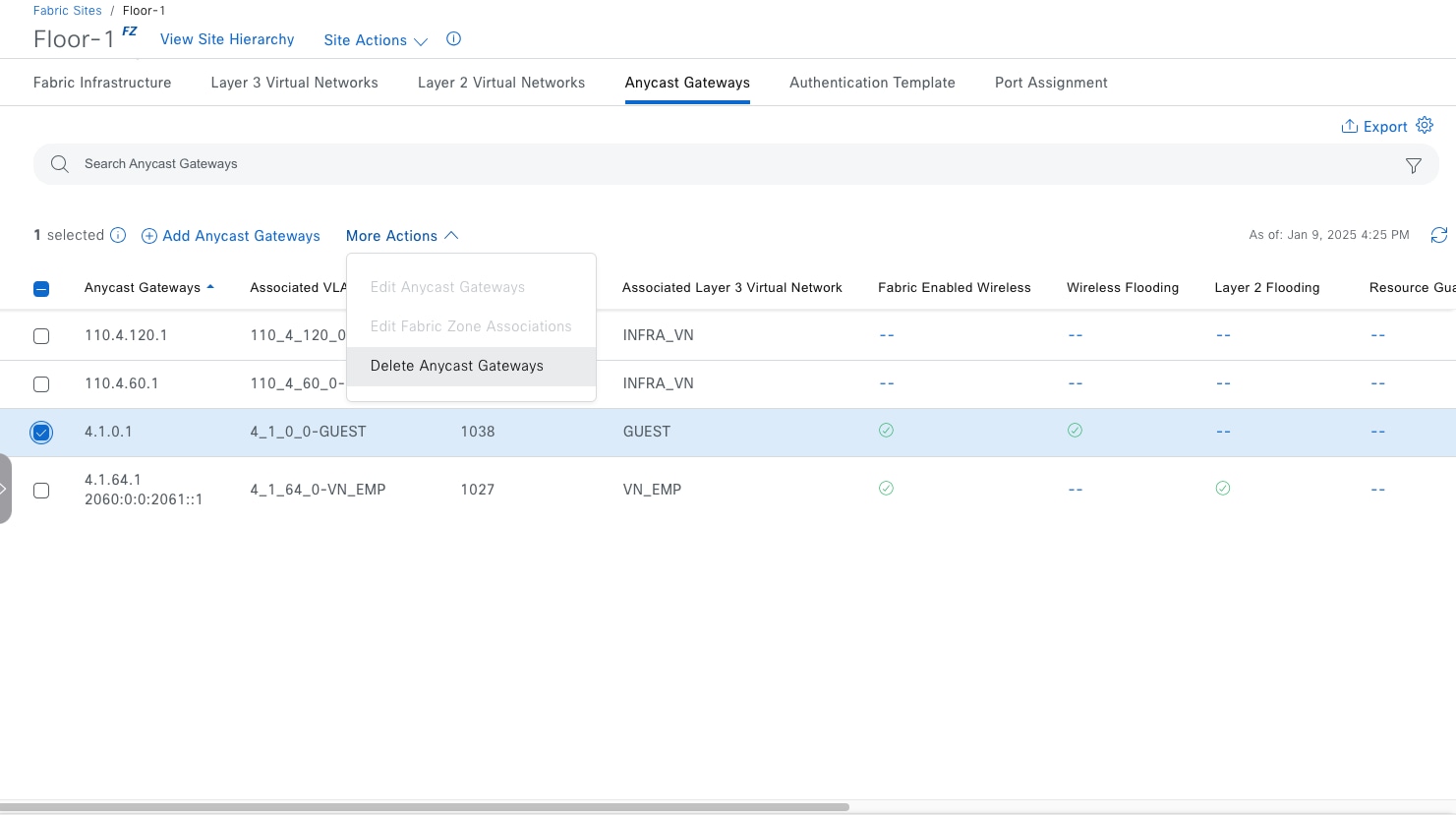
Step 3. Apply the change to deploy the task.
Method 2: Delete 4.1.0.1 from Floor-1 on the site level.
Step 1. From the top-left corner, click the menu icon and choose Provision > Fabric Sites > Control‑center.
Step 2. Click the Anycast Gateways tab, check the 4.1.0.1 check box, then choose More Actions > Edit Fabric Zone Associations.
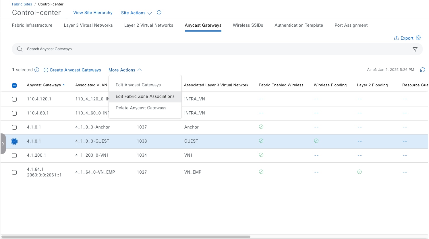
Step 3. In the workflow, click Select Fabric Zones.
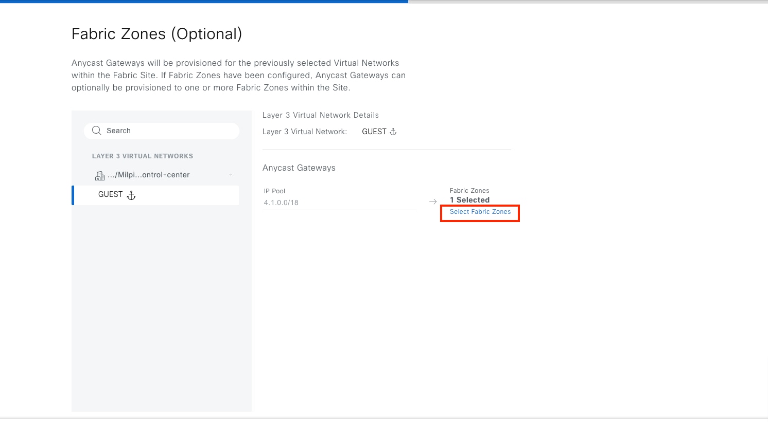
Step 4. Choose the zone, click Remove Selected then click Assign.
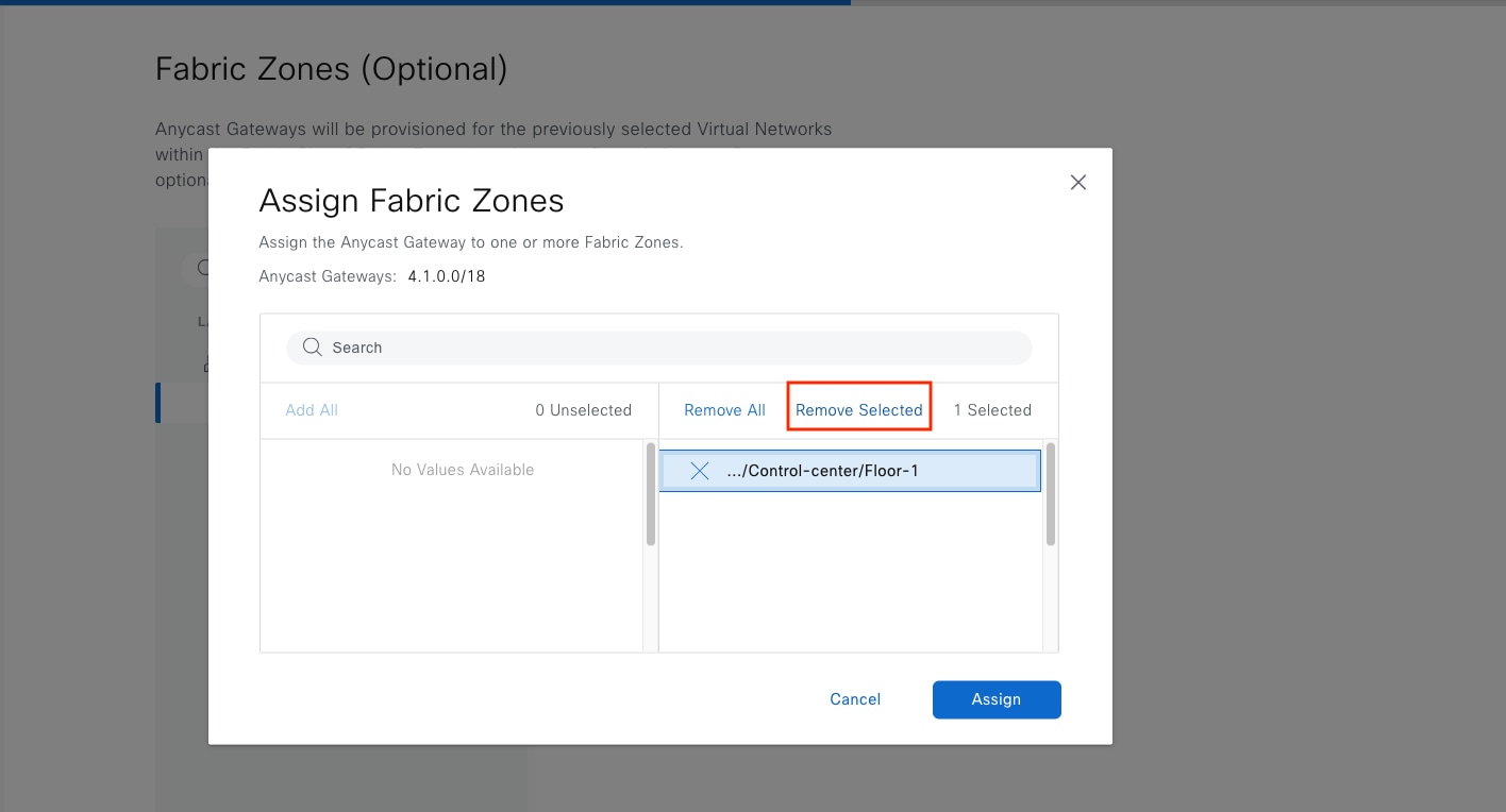
Step 5. Complete the workflow and deploy the task.
Procedure 2. Delete an anycast gateway from an inherited site
The anycast gateway 4.1.0.1 is added to inherited site Cisco-building-9.
To delete anycast gateway 4.1.0.1:
Step 1. From the top-left corner, click the menu icon and choose Provision > Fabric Sites, click the table view icon in the top right, click the Cisco-building-9 text link.
Step 2. Click the Anycast Gateways tab, check the 4.1.0.1 check box, then choose More Actions > Delete Anycast Gateways.
Step 3. Apply the change to deploy the task.
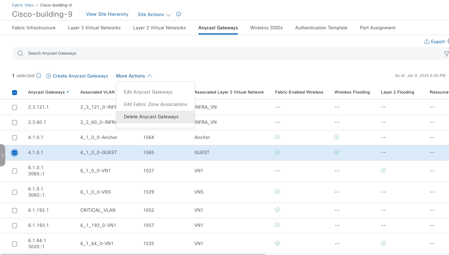
Procedure 3. Delete an anycast gateway from a fabric site
Step 1. From the top-left corner, click the menu icon and choose Provision > Fabric Sites > Control‑center.
Step 2. Click the Anycast Gateways tab, check the 4.1.0.1 check box, then choose More Actions > Delete Anycast Gateways.
Step 3. Apply the change to deploy the task.
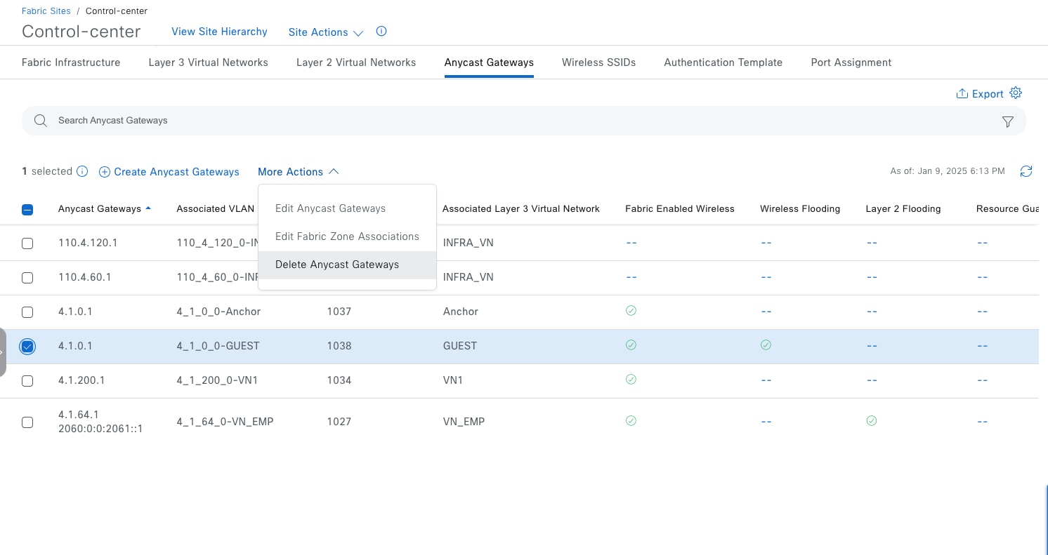
A fabric zone can be disabled only if there are no devices, such as fabric edges, extended nodes, policy extended nodes, or SBEN, assigned in the zone, and there is no anycast gateway assigned in the zone.
Step 1. Delete devices. Follow Delete Devices- Procedure 1a.
Step 2. Delete anycast gateway. Follow Delete anycast gateways.
Tech tip: You can also do Step 2 first and Step 1 second.
Step 3. Disable a fabric zone on either the site level or the zone level.
Method 1: Disable a fabric zone on a site level:
Step 1. From the top-left corner, click the menu icon and choose Provision > Fabric Sites > Control‑center then choose Site Actions > Edit Fabric Zone.
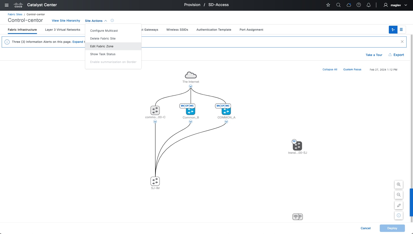
Step 2. Uncheck the check boxes for the floors to disable the zones.
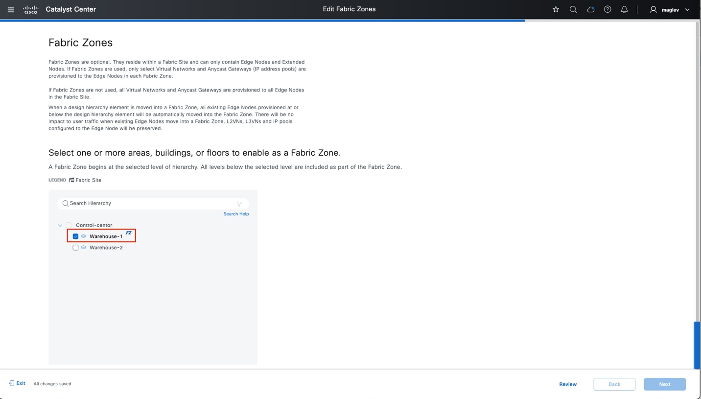
Method 2: Disable a fabric zone on the zone level.
Step 1. Navigate to the fabric zone.
Step 2. Choose Site Actions > Disable Fabric Zone.
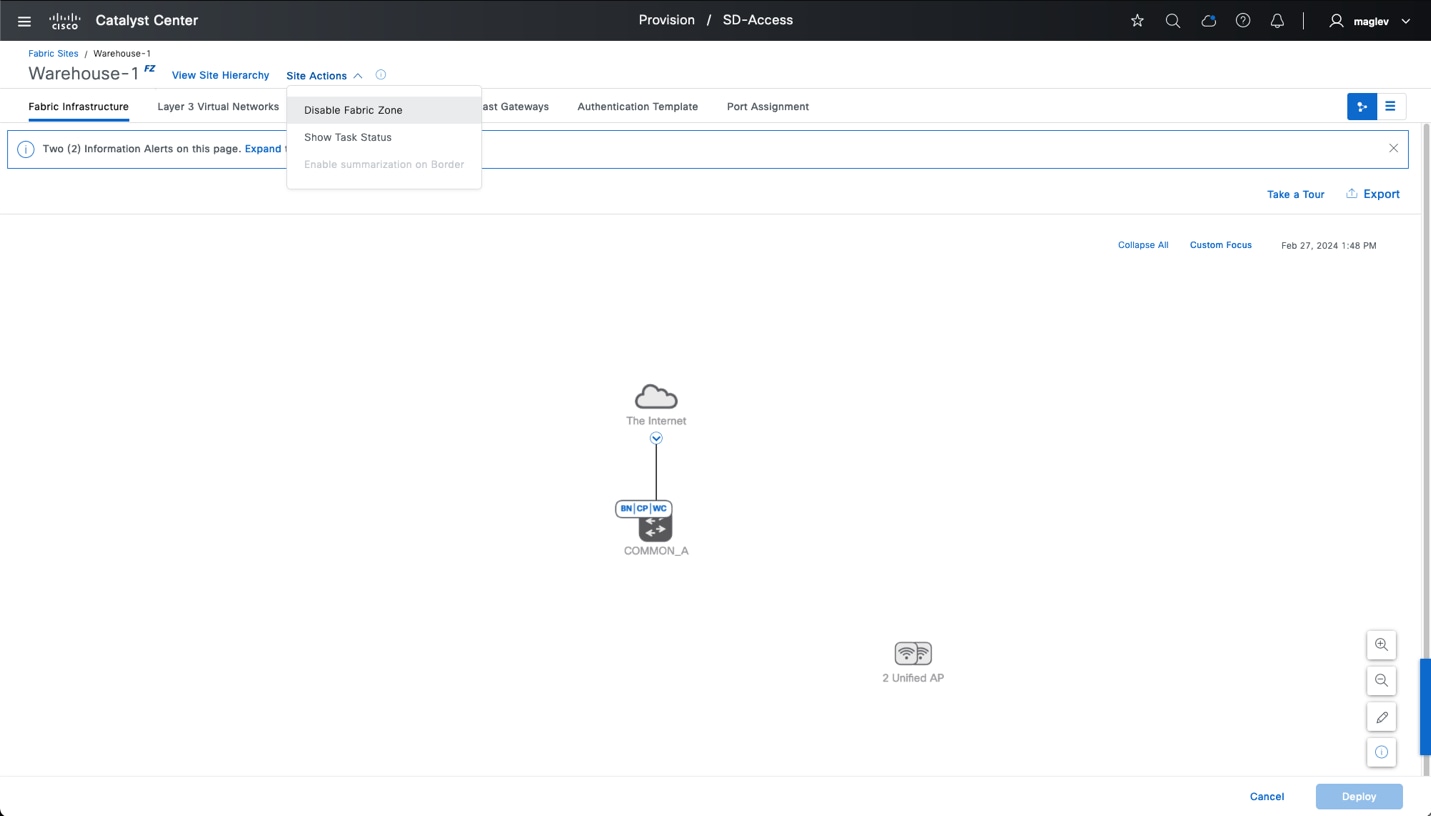
Delete fabric site
A fabric site can be deleted only if there are no fabric devices, no anycast gateway, no layer VN, no anchor VN, no fabric zone, and no multicast. If multicast is enabled, delete multicast first.
To delete multicast:
Step 1. Navigate to the fabric site then choose Site Actions > Remove Multicast Configuration.
Step 2. Delete the anycast gateway. Follow Delete anycast gateways.
Step 3. If an anchored VN is configured, delete the anchored anycast gateway and anchored VN from inherited sites then do either of these:
● Disable the anchoring on these VNs. There is no need to delete VNs from the fabric site.
● Remove directly from the fabric site. If layer 3 handoff is configured on these VNs, the layer 3 handoff must be deleted from fabric borders.
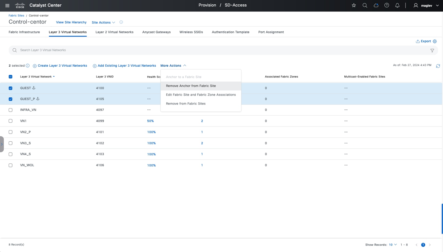
Step 4. Delete fabric devices. Follow Delete Devices- Procedure 1. Follow the sequence to delete fabric devices, such as extended nodes, policy extended nodes, SBENs, fabric edges, wireless controllers, fabric borders, and control plane nodes.
Step 5. Disable the fabric zone. Follow Disable Fabric Zone - Step 3.
Step 6. Navigate to the fabric site, choose Site Actions > Delete Fabric Site then proceed with the deployment.
Note: If there is a transit control plane device in the site, delete it before deleting the fabric site.
To delete a transit control plane device:
Step 1. Navigate to Provision > SD-Access > Transits.
Step 2. Choose the applicable transit and delete it.
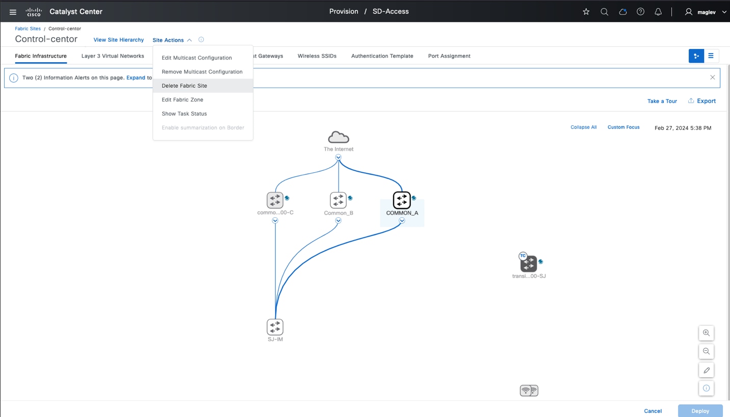
This section covers the day-to-day health checking on a Cisco SD-Access network using the Catalyst Center Assurance application, monitoring Cisco SD-Access application health using the System Health tool, and validating device eligibility when adding it to a fabric site using the Cisco SD-Access Compatibility Matrix.
Catalyst Center Assurance provides a comprehensive solution for better and consistent service-levels to meet growing business demands. It addresses reactive network monitoring and troubleshooting, and proactive and predictive aspects of running a network to ensure optimal client, application, and service performance.
Assurance provides benefits, including:
● Provides actionable insights into network, client, and application-related issues. These issues consist of basic and advanced correlation of multiple pieces of information, thus eliminating white noise and false positives.
● Provides both systems guided as well as self-guided troubleshooting. Assurance offers a system-guided method that correlates multiple Key Performance Indicators (KPIs). It uses results from tests and sensors to identify the root cause of a problem and then suggests possible actions to resolve it. The focus is on highlighting the issue rather than monitoring data. Frequently, Assurance performs the work of a Level 3 support engineer.
● Provides in-depth health scores for a network and its devices, clients, applications, and services. Client experience is assured both for access (onboarding) and connectivity.
The Catalyst Center System Health tool helps validate application health, system status, and upgrade readiness.
Catalyst Center periodically compares operational Cisco SD-Access fabric nodes hardware and software attributes against information in the Cisco SD-Access Compatibility Matrix and blocks new devices from being added into a fabric site if any compatibility issues are detected.
Assurance for overall health
The Overall Health Dashboard provides an overview of how well the network and client devices are running, along with a view of the top 10 issues that require attention. From here, drill down into network health or client health for a more detailed view of how well the network infrastructure and the clients are running, as demonstrated in this procedure example.
Step 1. From the top-left corner, click the menu icon and choose Assurance > Health then click the Overall tab.
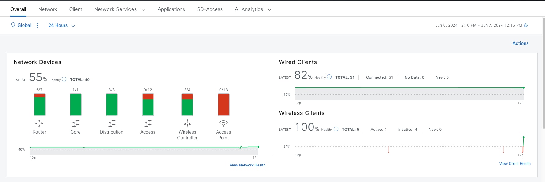
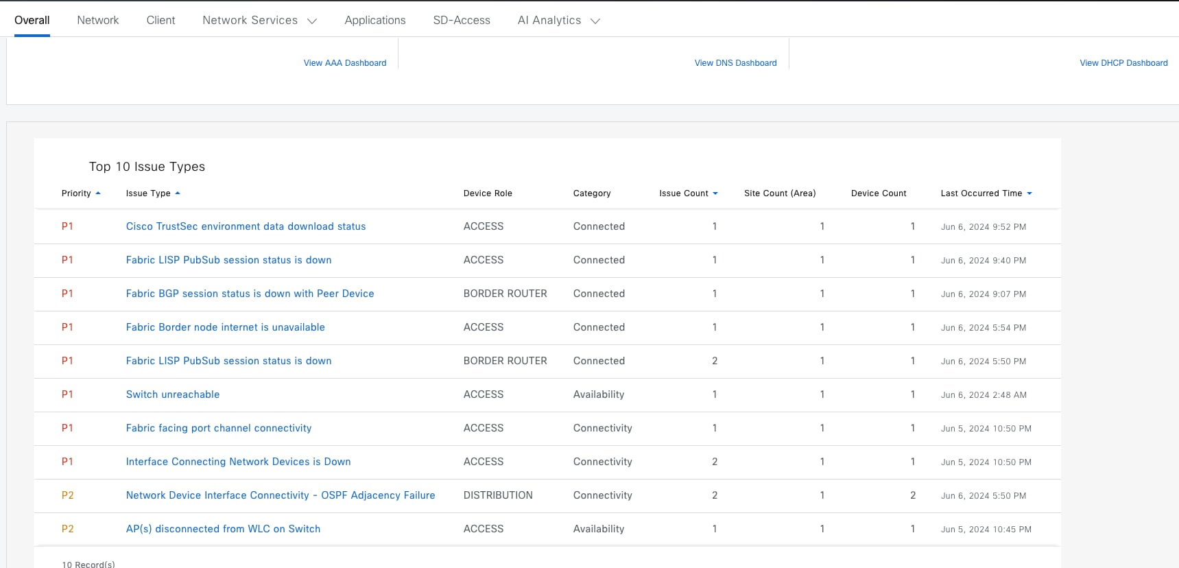
Step 2. Click the individual issue to see the details then follow the suggested actions.
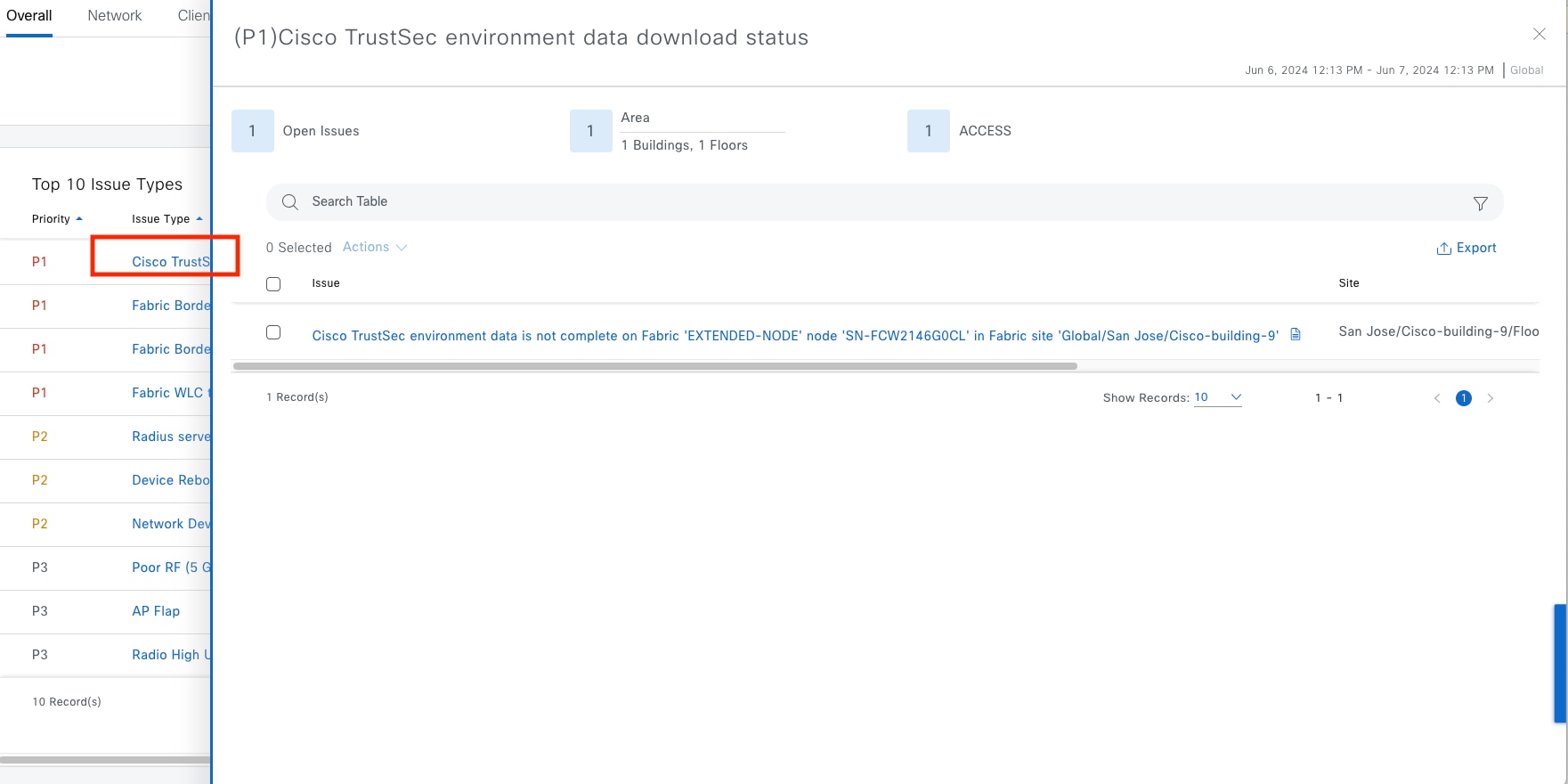
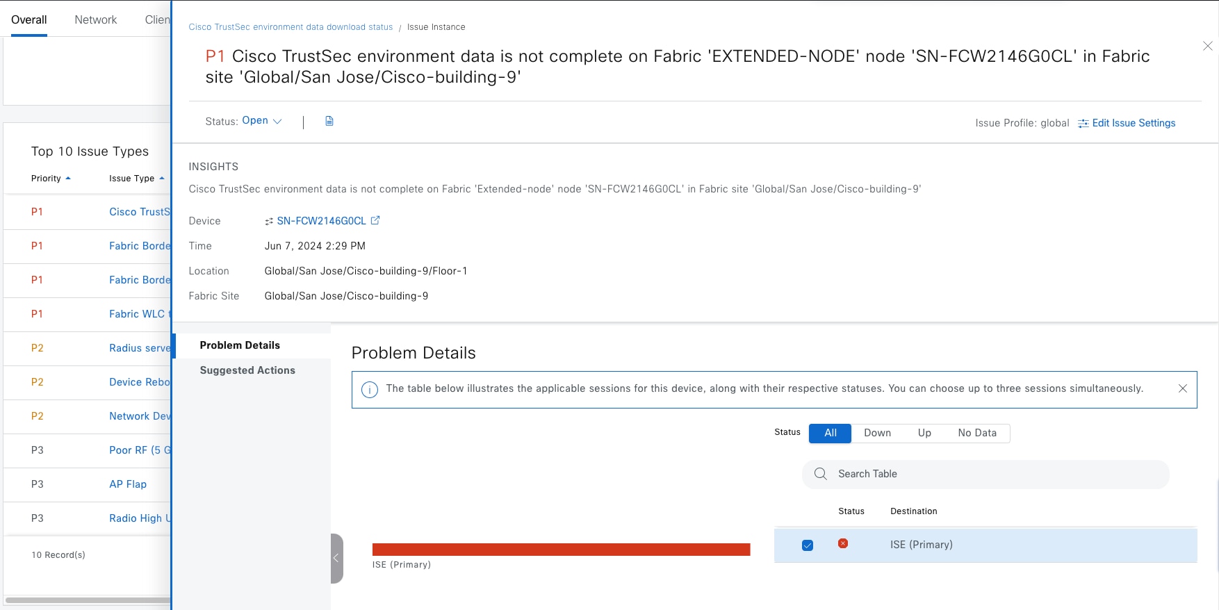
Assurance for network health
Individual network device health scores are computed based on system, data plane and control plane health. Network devices include routers, switches, wireless controllers and APs. Clients and devices in maintenance mode are not part of the network health score.
The overall network health is a percentage computation of healthy devices divided by the total number of devices by type that are being monitored by Catalyst Center, as shown in the procedure figures.
Step 1. From the top-left corner, click the menu icon and choose Assurance > Health then click the Network tab.
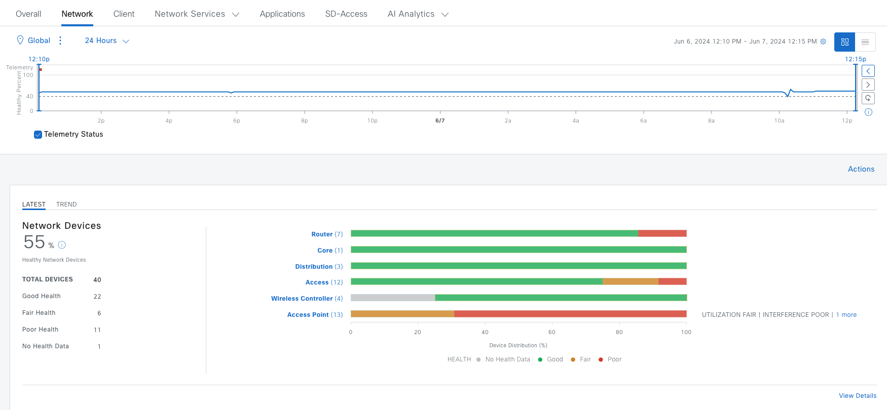
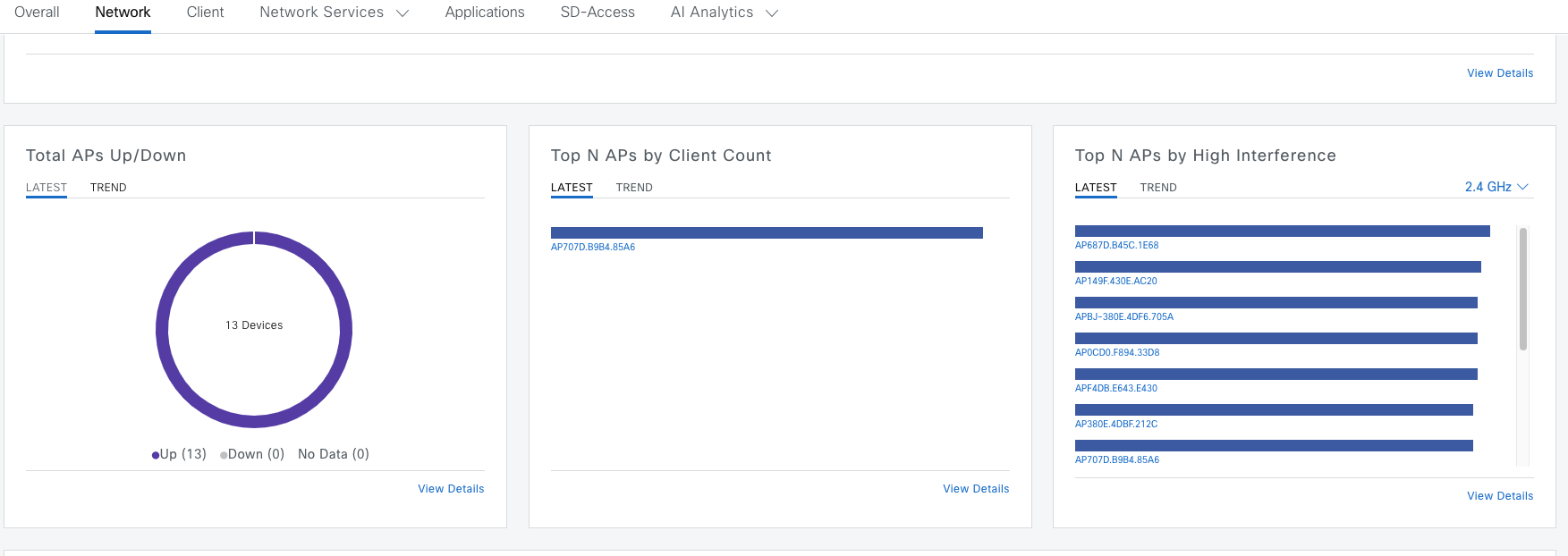
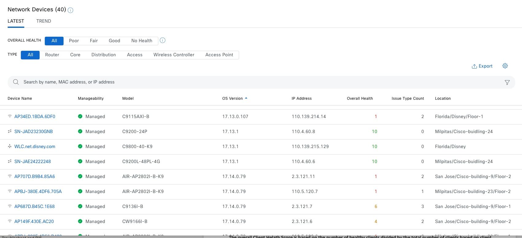
Step 2. Use a filter to filter out the devices by heath status or device type. Use Search for specific device sets.
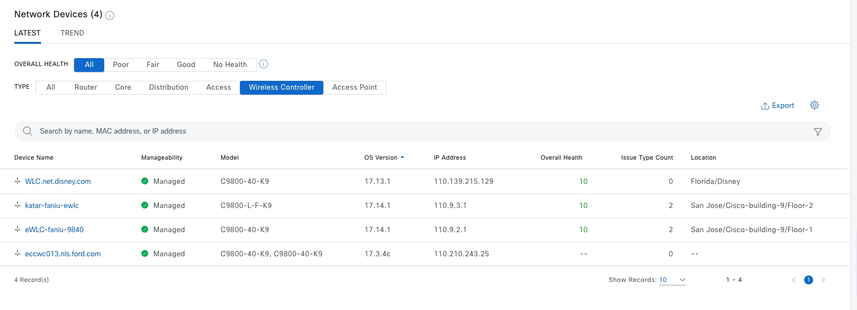
Note: The network health score exists only in the context of a location. If the location of a device is not available, it is not counted in the network health score. If a device is not provisioned, its heath is not monitored. Refer to the last wireless controller in figure, it has no health score.
Step 3. Click the device of interest to be redirected to the Device 360 window then review the detailed health information.
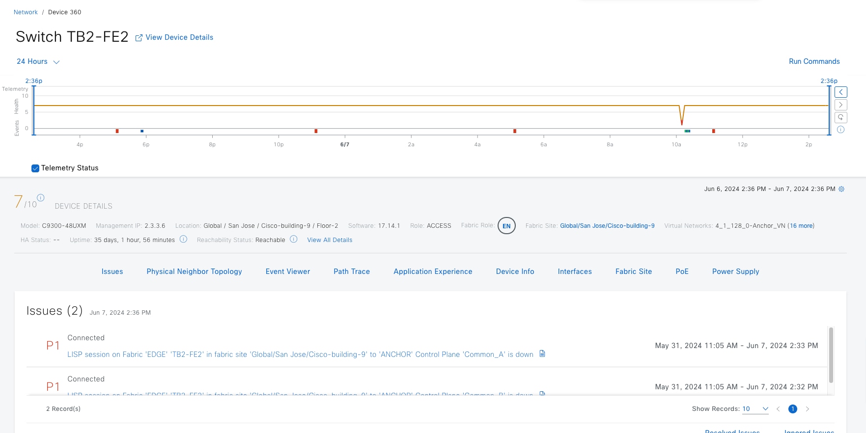
Assurance for client health
Individual client health scores are computed based on initial onboarding, as well as the persistent connectivity experience. The Client Health Dashboard provides an analytical summary of how well clients can connect to the network. After the clients are connected, the dashboard details the client connectivity experience.
The overall client health score is based on the number of healthy clients divided by the total number of clients based on client type (wired or wireless).
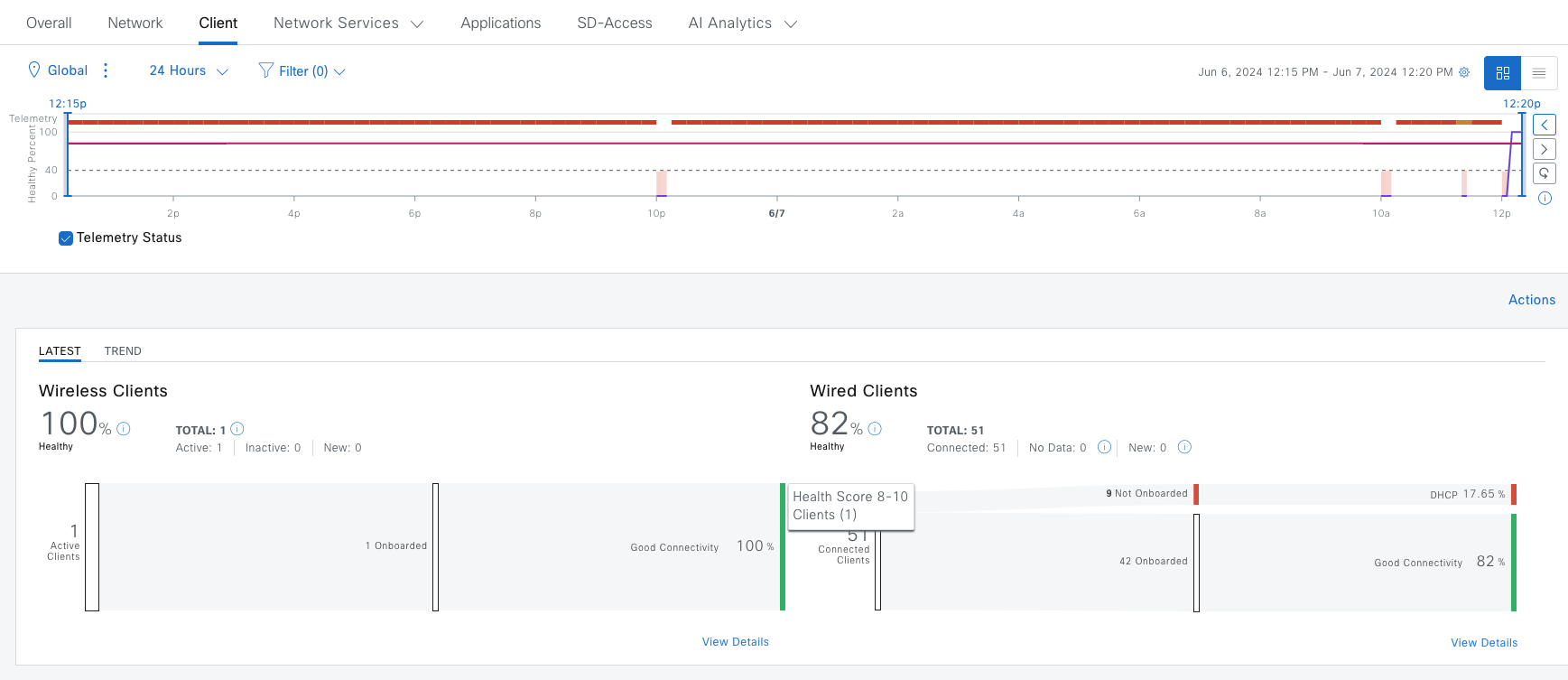
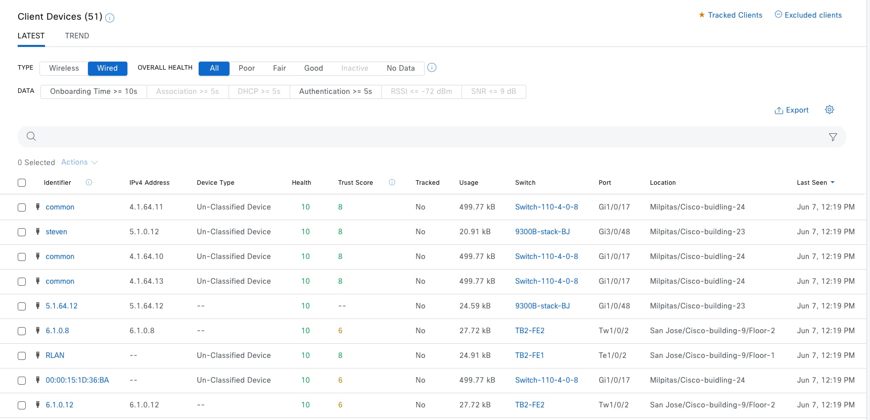
Step 1. Similar to the Network Heath window, use a filter and the Search function to locate clients.
Step 2. Click the client to be redirected to Client 360 window then review the details.
Example Figure 69 and Figure 70 show the details for clients in the Client 360 window.
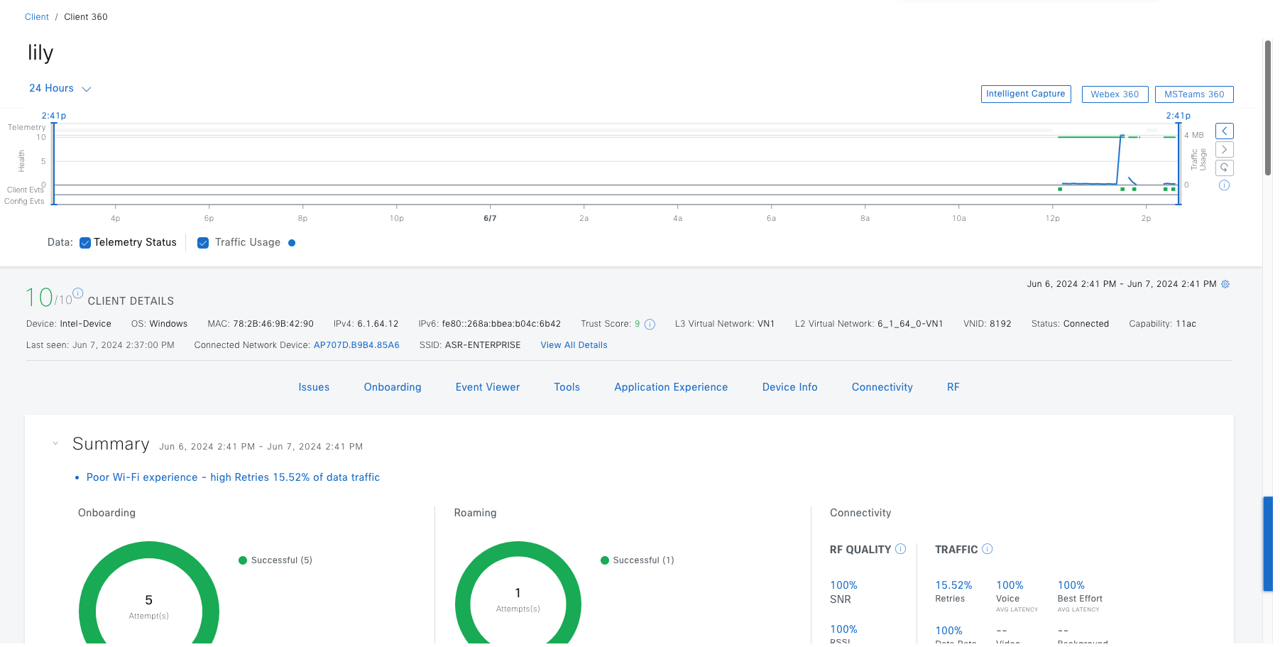
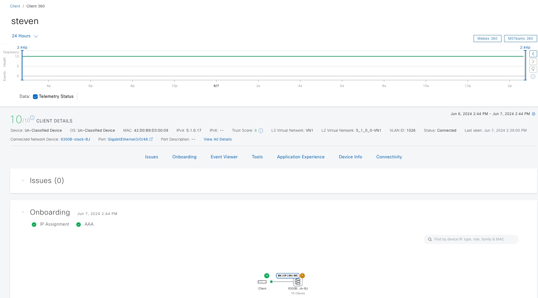
Assurance for Cisco SD-Access
Cisco SD-Access Assurance provisions telemetry subscriptions on devices operating in fabric roles to gather near real time assurance data. This capability requires the fabric devices to be configured for NETCONF, discovered with NETCONF, and to have Catalyst Center telemetry enabled.
After a Catalyst Center upgrade, provision a new telemetry subscription on the devices.
Step 1. From the top-left corner, click the menu icon and choose Provision > Inventory, if there are new telemetry subscriptions, a banner displays at the top of the Inventory window.
Step 2. Click Apply Fix to push the new telemetry subscriptions. Catalyst Center automatically selects devices that need updating.
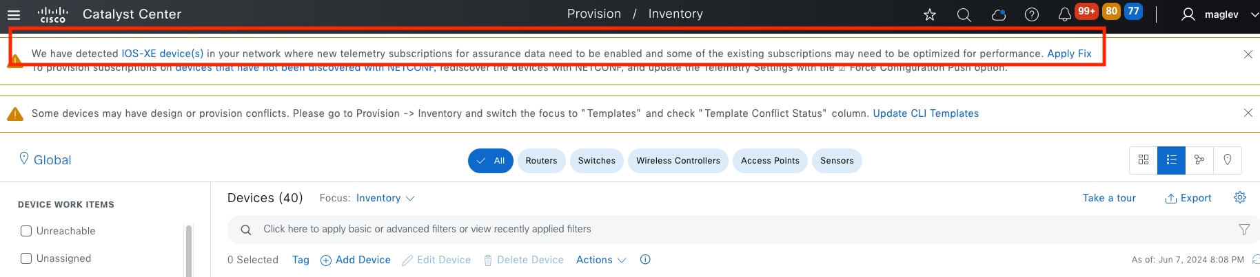
To check Cisco SD-Access health in Assurance:
Step 1. From the top-left corner, click the menu icon and choose Assurance > Health then click the SD‑Access tab.
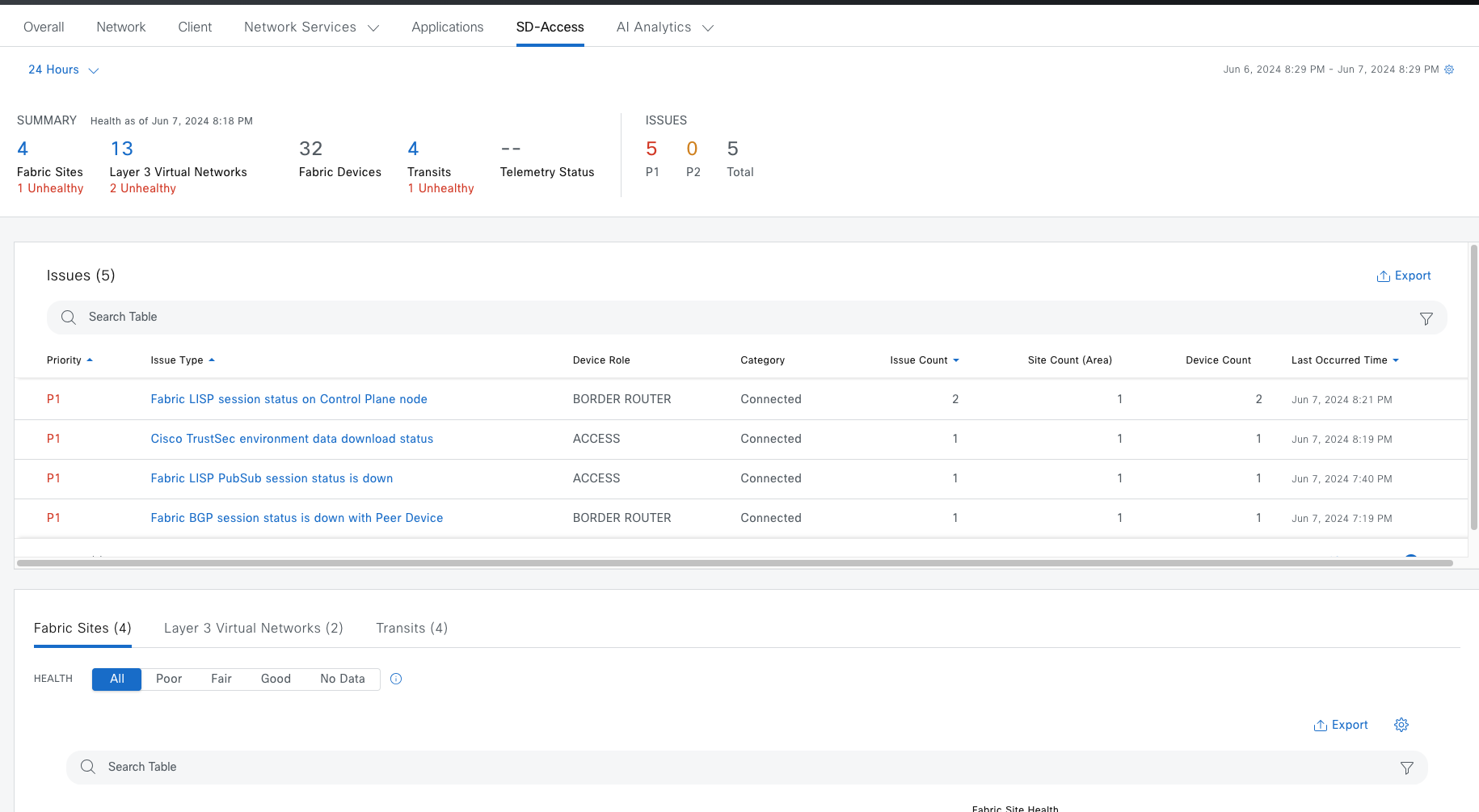
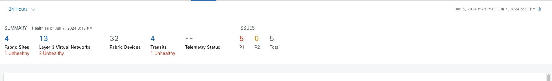
| Item |
Description |
| Summary |
◦ Fabric Sites: Number of fabric sites. ◦ Layer 3 Virtual Networks: Number of layer 3 virtual networks. ◦ Fabric Devices: Number of fabric devices. ◦ Transits: Number of transits and peer networks. ◦ Telemetry Status: Displays the telemetry status of the fabric sites. |
| Issues |
◦ P1: Number of priority 1 issues. ◦ P2: Number of priority 2 issues. ◦ Total: Total number of P1, P2, and P3 issues |
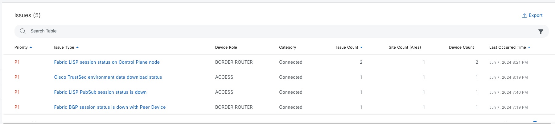
Top 10 issues display if any must be addressed. The issues are color coded and sorted by their preassigned priority level, starting with P1.
Step 2. Click an issue to open a slide-in pane with additional details about the issue type.
Step 3. From the slide-in pane, click an issue instance where, as required, you can:
● To resolve the issue, choose Status > Resolve.
● To ignore the issue:
a. Choose Status > Ignore.
b. Set the number of hours to ignore the issue on the slider and confirm.
● To check the details of the issue, click the issue.
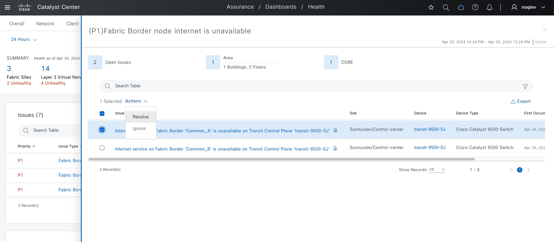
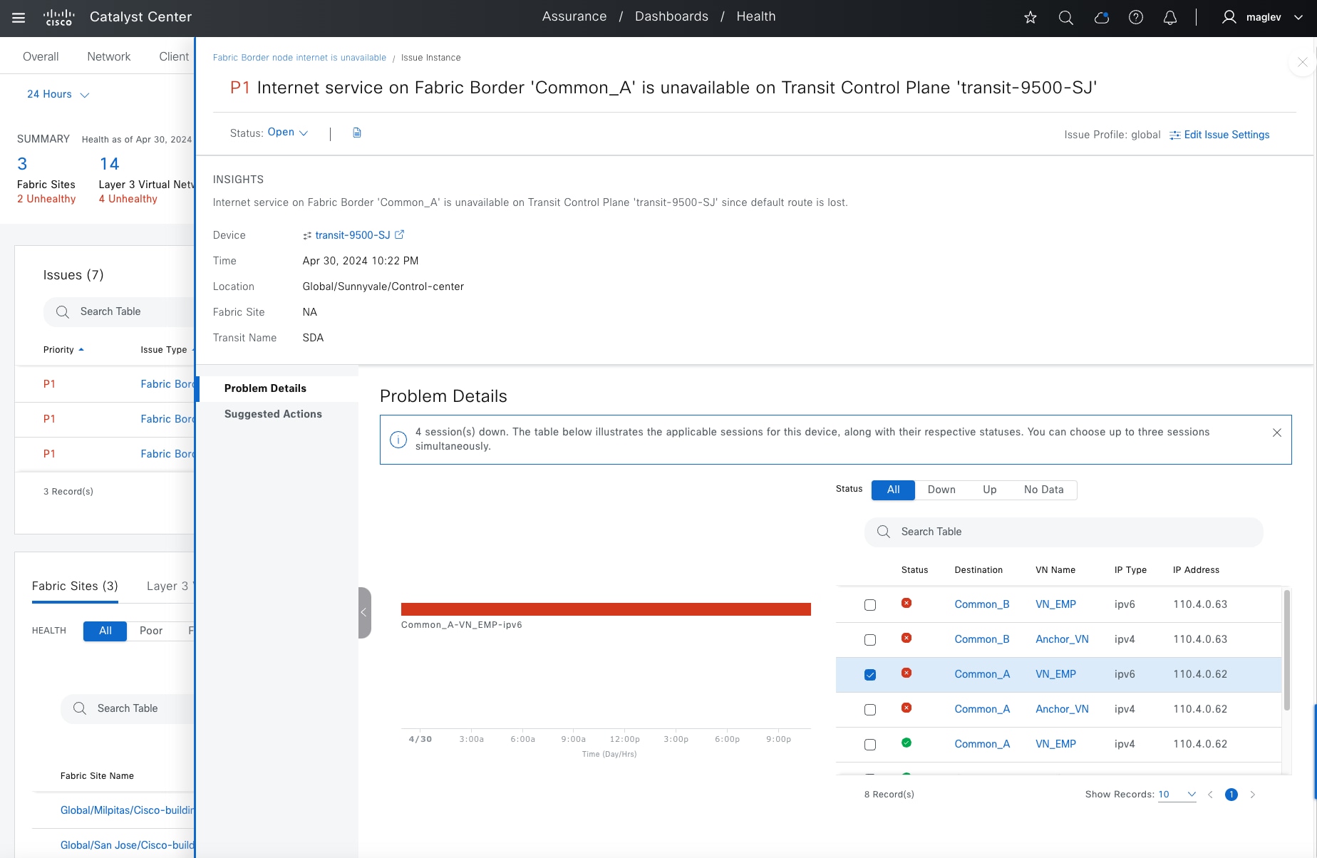
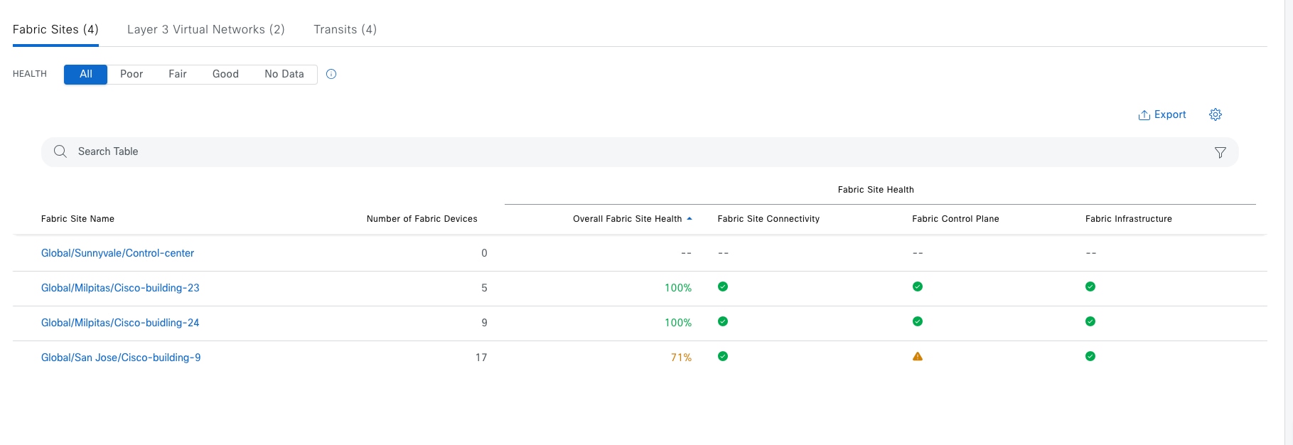
View detailed fabric site information in the table format. The fabric site table displays this information by default:
● Fabric Site Name: Name of the fabric site
● Number of Fabric Devices: Number of fabric devices in the fabric site
● Fabric Site Health:
◦ Overall: Overall health of the fabric site. Click the name to be redirected to the Fabric Site 360 window. See Monitor the Health of a Fabric Site.
◦ Fabric Site Connectivity: Health of the connectivity with the fabric site
◦ Fabric Control Plane: Health of the control plane in the fabric site
◦ Fabric Infrastructure: Health of the devices that make up the fabric site
Filter the table based on the client health with these options:
● All
● Poor: Fabric sites with a health score range from 1 to 3
● Fair: Fabric sites with a health score range from 4 to 7
● Good: Fabric sites with a health score range from 8 to 10
● No Data: Fabric sites with no data
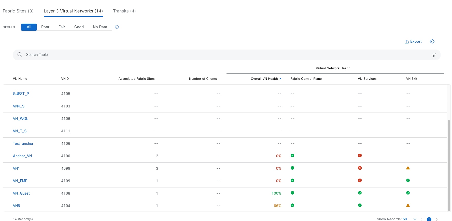
View the detailed VN table information. The VN table displays this information by default:
● VN Name: Name of the VN. Click the name to be redirected to VN360 window. See Monitor the health of a layer 3 VNs with VN 360.
● Associated Fabric Sites: Number of Associated sites in the VN
● Number of Clients: Number of endpoints in the VN
● Virtual Network Health:
◦ Overall VN Health: Overall health of the VN
◦ Fabric Control Plane: Health of the control plane in the VN
◦ VN Services: Health of the VN services
◦ VN Exit: Health of BGP sessions to peer devices
Note: Layer 3 Virtual Networks does not monitor INFRA_VN, only customized VN and Default_VN (if in use)
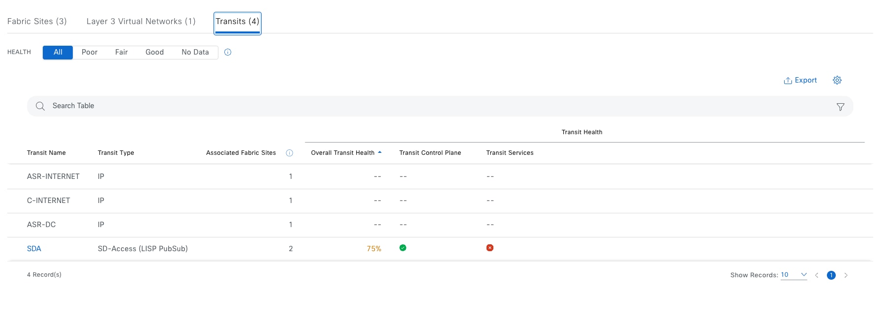
View detailed transits and peer network information in a table format. The transits and peer network table displays this information by default:
● Transit Name: Name of the transit network or peer network. See Monitor the health of layer 3 VNs with VN 360.
● Transit Type: IP or SD-Access
● Associated Fabric Sites: Number of associated sites
● Transit Health:
◦ Overall: Overall health of the transit and peer network
◦ Transit Control Plane: Health of the transit control plane
◦ Transit Services: Health of internet availability
Monitor the health of a fabric site
As shown in the Fabric Dashlet section, click the fabric site to view the detailed health information of a site.
Use the health timeline slider to view the health score for a more granular time range and to view quality information.
Hover the cursor within the timeline to view information, including:
● Fabric Site Health: Health is the percentage of healthy fabric nodes in this site.
Click a hyperlinked fabric category in the charts to open a side pane to view the respective KPI subcategories.
| KPI name |
KPI subcategorized |
Issue auto resolve |
Max latency (issue/health score) |
Use |
| AAA Server Status |
Fabric Infrastructure |
yes |
10 min/10 min |
Monitors the server status for each AAA server from edge and extended nodes |
| CTS Environment Data Download |
Fabric Infrastructure |
yes |
10 min/10 min |
Monitors the download of Cisco TrustSec environment data on edge, PEN and SBEN for the Cisco ISE Server. If AAA Server Status is down; Cisco TrustSec health is automatically brought down as well. |
| Extended Node Connectivity |
Fabric Site Connectivity |
No |
5min/5min |
Monitors the link status between extended and edge nodes on configured port channels |
| Control plane reachability |
Fabric Site Connectivity |
no |
10 min/10 min |
monitors the IPSLA reachability status from fabric wireless controller nodes to local control plane nodes |
| LISP Session Status |
Fabric Control Plane |
yes |
10 min/10 min |
Monitors the LISP protocol sessions from border and edge nodes to local control plane nodes. |
| Pub/Sub Session Status for INFRA_VN |
Fabric Infrastructure |
yes |
10 min/10 min |
Monitors Pub/Sub protocol sessions from border nodes to local control plane nodes for INFRA_VN. |
| BGP session from Border to Control Plane |
Fabric Site Connectivity |
yes |
10 min/10 min |
Monitors the BGP session state from a given border node to local control plane nodes for INFRA_VN only. |
| BGP session from Border to Peer Node for Infra_VN |
Fabric Site Connectivity |
yes |
10 min/10 min |
Monitors the BGP session state from a given border node and its' nonfabric peers. Sessions are tracked for INFRA_VN only, and for both LISP/BGP and LISP with Pub/Sub protocol sites. |
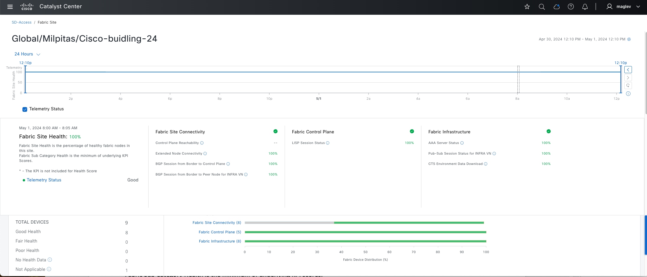
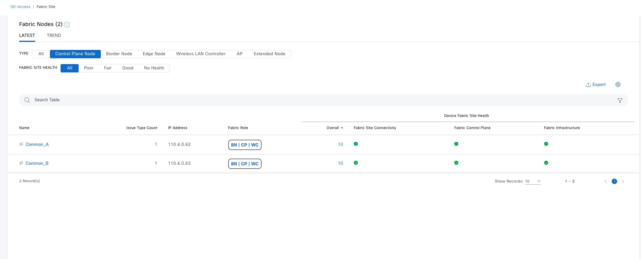
| Item |
Description |
| Type |
Filter the table based on the fabric node type with these options: All, Fabric Control Plane, Fabric Border, Fabric Edge, Fabric wireless controller, Fabric AP, and Extended Node. |
| Fabric Site Health |
Filter the table based on the overall health score of the fabric site with these available options:
● All
● Poor: Devices with a health score range from 1 to 3.
● Fair: Devices with a health score range from 4 to 7.
● Good: Devices with a health score range from 8 to 10.
● No Health: Devices with no health data.
|
| Fabric Node table |
View device information for all the fabric nodes for the selected site in a table format. Note: The overall health score is the minimum subscore of KPI metric health scores for fabric site connectivity and fabric infrastructure. The Name, Issue Type Count, and Fabric Role columns display the fabric name, issue count, and fabric role (Edge, Border, Map Server, and so on). Under Device Fabric Site Health, in the Overall column, hover the cursor over a health score. The overall Device Fabric Site Health score is displayed along with the health and percentage value of all the KPI metrics. Hover the cursor over the Fabric Site Connectivity, Fabric Control Plane, and Fabric Infrastructure icons to display the health scores. |
Monitor the health of layer 3 VNs with VN 360
As shown in previous section, click the VN to view the detailed health information of a specific VN.
The VN health score is the percentage of healthy devices in the VN. VN category health is the minimum of corresponding subcategory KPI scores. VN services includes the BGP session from border to peer node, multicast (external RP), default route registration, and VN control plane.
Displayed by default. The left pane provides the VN health summary score and the total number of devices. The right pane displays charts.
● Healthy fabric nodes: The percentage of healthy (good) nodes in the selected site.
● Total devices: Total number of fabric devices and the count of devices with Good Health, Fair Health, Poor Health, and No Health data.
● Charts: This color-coded, snapshot-view chart shows the KPIs with subcategories.
| KPI name |
Subcategories |
Issue auto resolve |
Max latency (issue/health score) |
Use |
| Pub/Sub Session Status |
Fabric Control Plane |
yes |
10 min/10 min |
Monitors Pub/Sub protocol sessions from border nodes to connected local control plane nodes for all VN, except for INFRA_VN and inherited VNs for FiaB nodes. |
| Internet Availability |
VN service |
yes |
10 min/10 min |
Monitors the default route on external borders and registers that with the control plane node within a LISP with Pub/Sub site |
| Multicast (External RP) |
VN service |
no |
10 min/10 min |
Monitors the reachability status to the external Multicast RP. |
| BGP session from Border to Peer Node |
VN exist |
yes |
10 min/10 min |
Monitors the BGP session state from a given border node and the nonfabric peers. Sessions are tracked for all configured VNs, with the exceptions of INFRA_VN, and for both LISP/BGP and LISP with Pub/Sub protocol sites. |
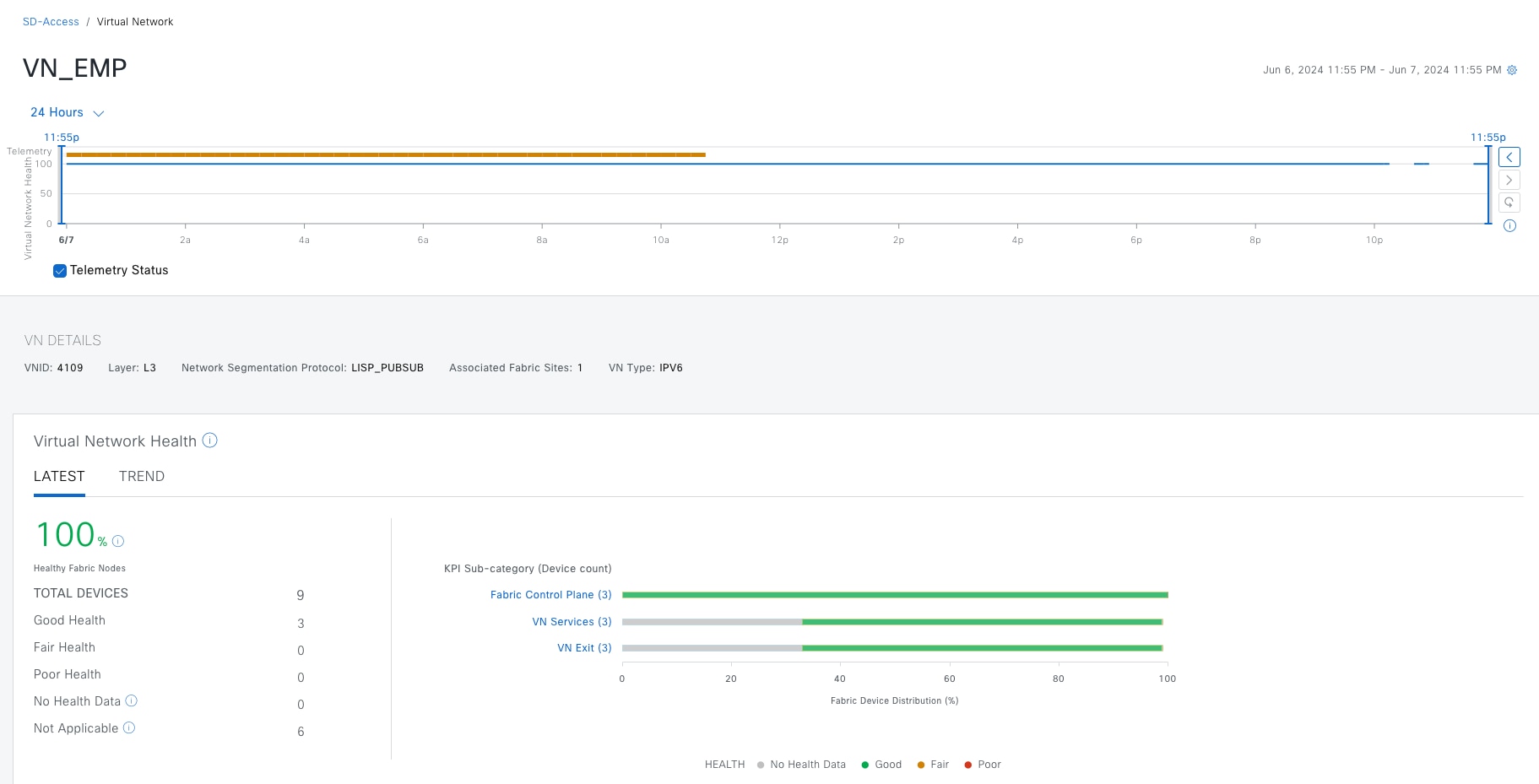
Hover the cursor over a color to display the health score and the number of devices that are associated with that color.
If the chart shows a low health score (red or orange), the KPIs that contributed to the low health score are provided next to the bar.
Click a hyperlinked category to open a side pane for more details.
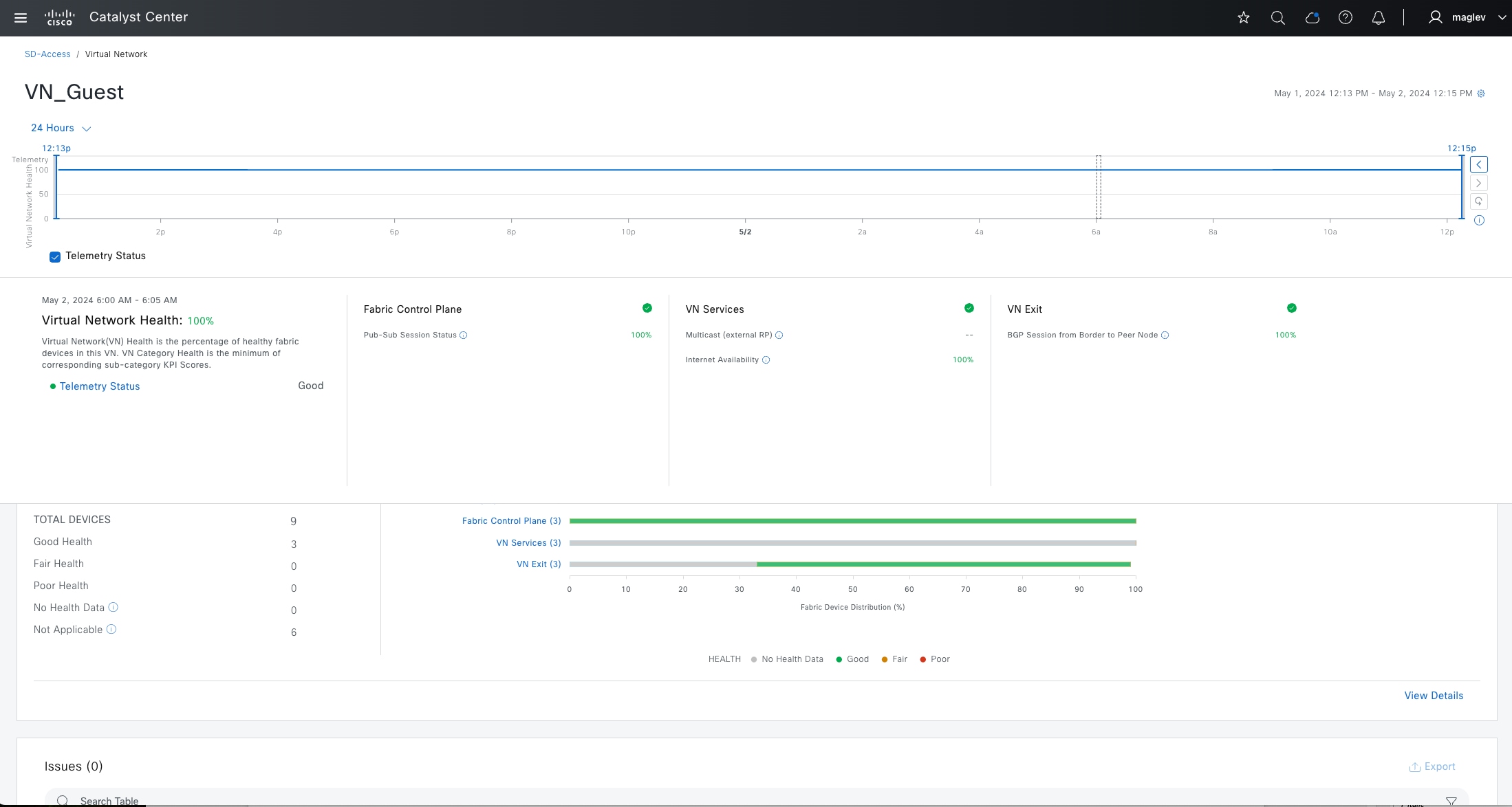
Monitor the health of transits – Transit 360
As shown in the previous section, click the transit (Cisco SD-Access type) to view the detailed health information of Cisco SD-Access transit.
Use the health timeline slider to view the health score for a more granular time range and to view quality information.
Hover the cursor within the timeline to view information, including:
● Transit Network Health: The health score is the percentage of healthy fabric nodes in this site; it does not include the device health of control planes. The fabric category health is the minimum of underlying KPI scores.
● Transit Site Control Plane: Lists the KPI subcategory, such as LISP and Pub/Sub session of the transits. If the transit health score is low, click View Device List to display a list of devices that contribute to the low score and their associated down sessions. Click of the hyperlinked name of the device to display device information.
Check the Telemetry Status check box below the timeline to view the horizontal bar in the timeline.
Displayed by default. Includes two panes. The left pane provides the network health summary score and the total number of devices. The right pane displays charts.
● Health Fabric Nodes: The percentage of healthy (good) nodes in the selected site.
● Total Devices: The total number of network devices and the count of devices with Good Health, Fair Health, Poor Health, and No Health Data.
● Charts: This color-coded snapshot-view chart shows the transit control plane over the last 5 minutes.
Step 1. Hover the cursor over a color to display the health score and the number of devices that are associated with that color.
Step 2. Click a hyperlinked Transit Control Plane in the charts to open a side pane to view these KPI subcategories in the transit control plane.
| KPI |
Issue auto resolve |
Max latency (issue/health score) |
Use |
| Pub/Sub Session from Border to Transit Site Control Plane |
yes |
10 min/10 min |
Monitors pub-sub protocol sessions from border nodes to local control plane nodes for INFRA_VN. |
| LISP Session from Border to Transit Site Control Plane |
yes |
10 min/10 min |
Monitors the LISP protocol sessions from border nodes to connected transit control plane nodes. |
| BGP Session from Border to Transit Control Plane |
yes |
10 min/10 min |
Monitors BGP session state from a given external border node and connected transit control plane nodes. Sessions are tracked for INFRA_VN within LISP/BGP protocol sites. |
Step 3. Click a hyperlinked Transit Service in the charts to open a side pane to view these KPI subcategories for the transit services:
| KPI |
Issue auto resolve |
Max latency (issue/health score) |
Use |
| Internet Availability |
yes |
10 min/10 min |
Monitors the default route on external borders and registers that with the transit plane node within a LISP with Pub/Sub site. |
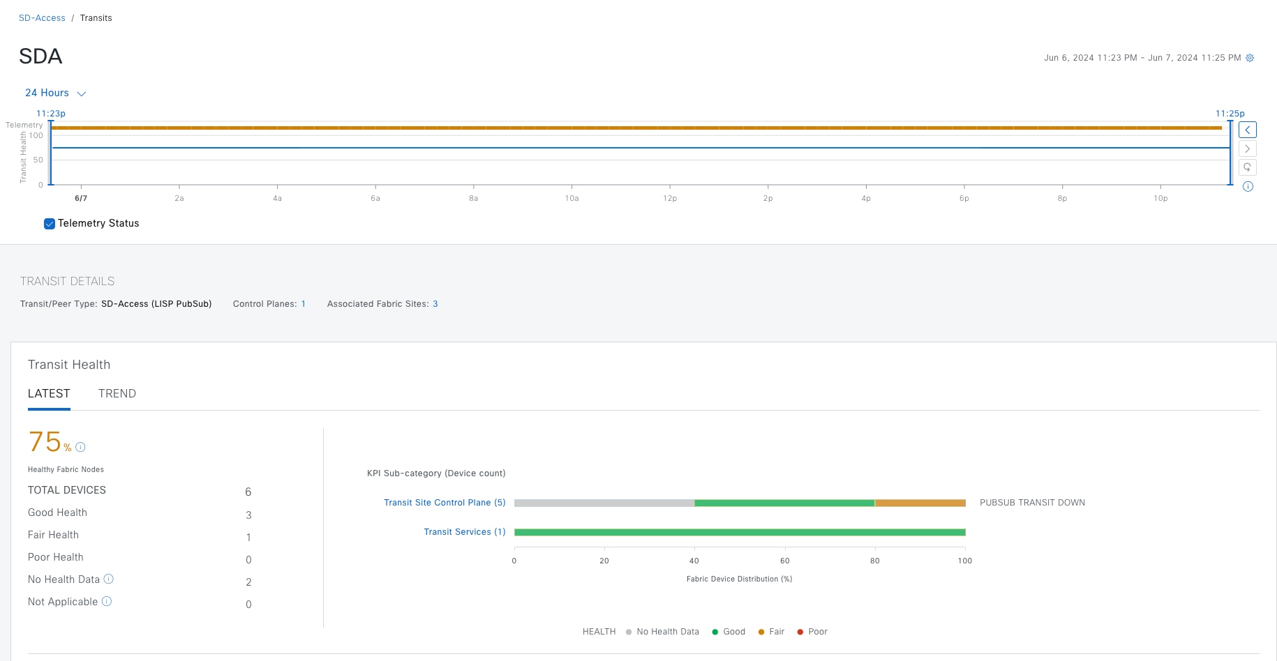
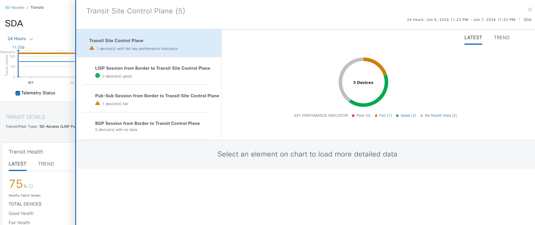
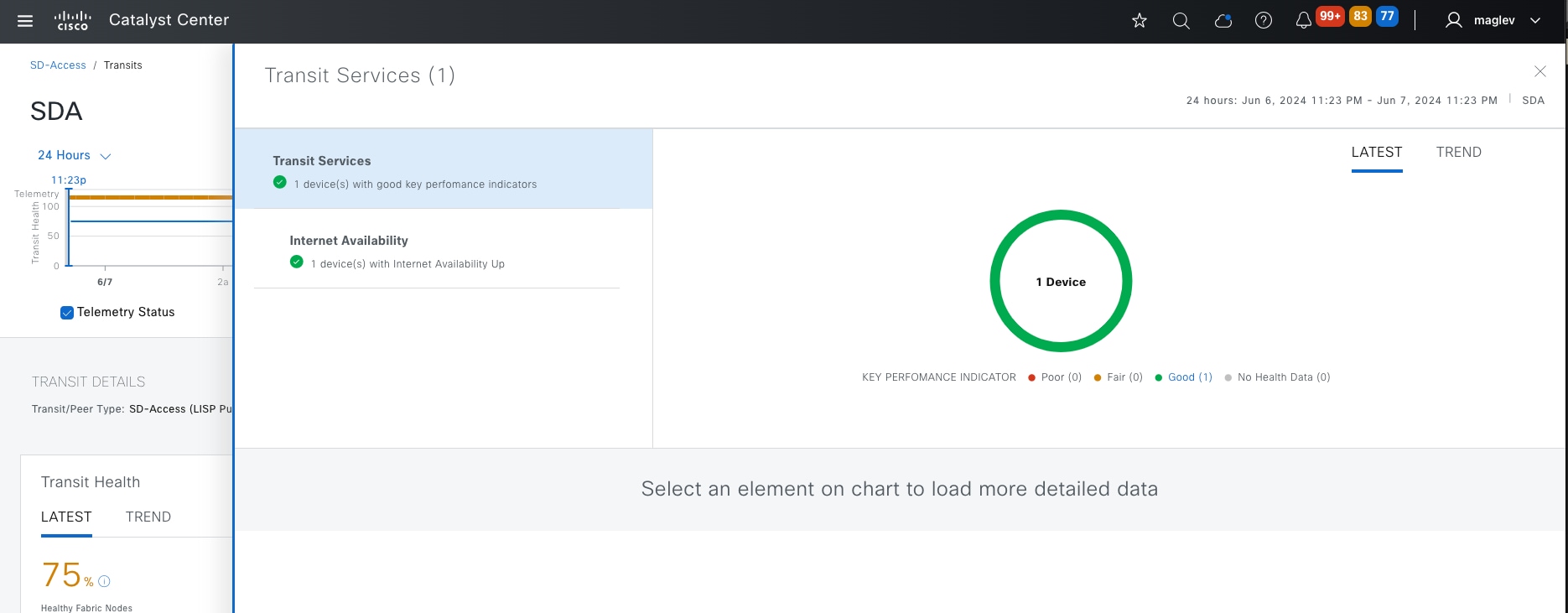
Step 4. Scroll down to the Top 10 issues to display Issues towards this transit and Associated Fabric Sites.
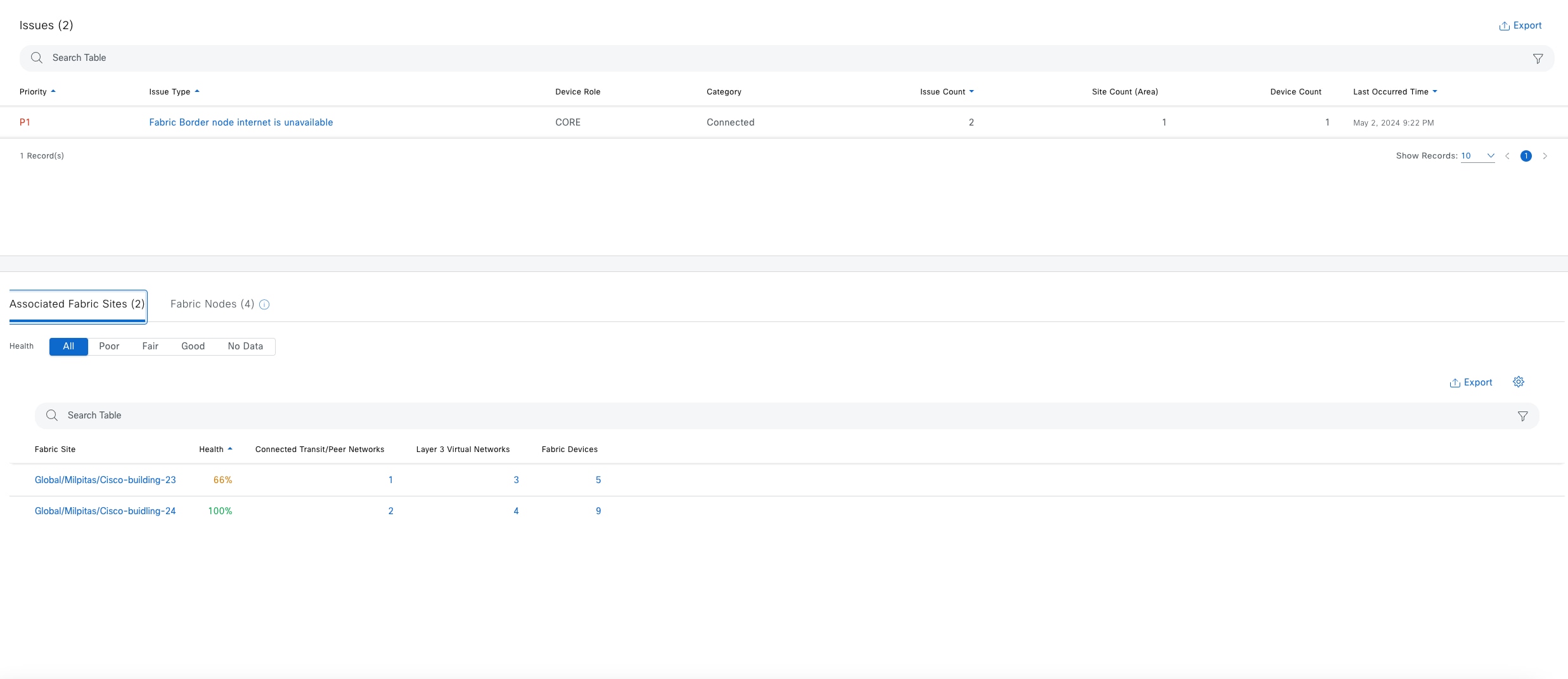
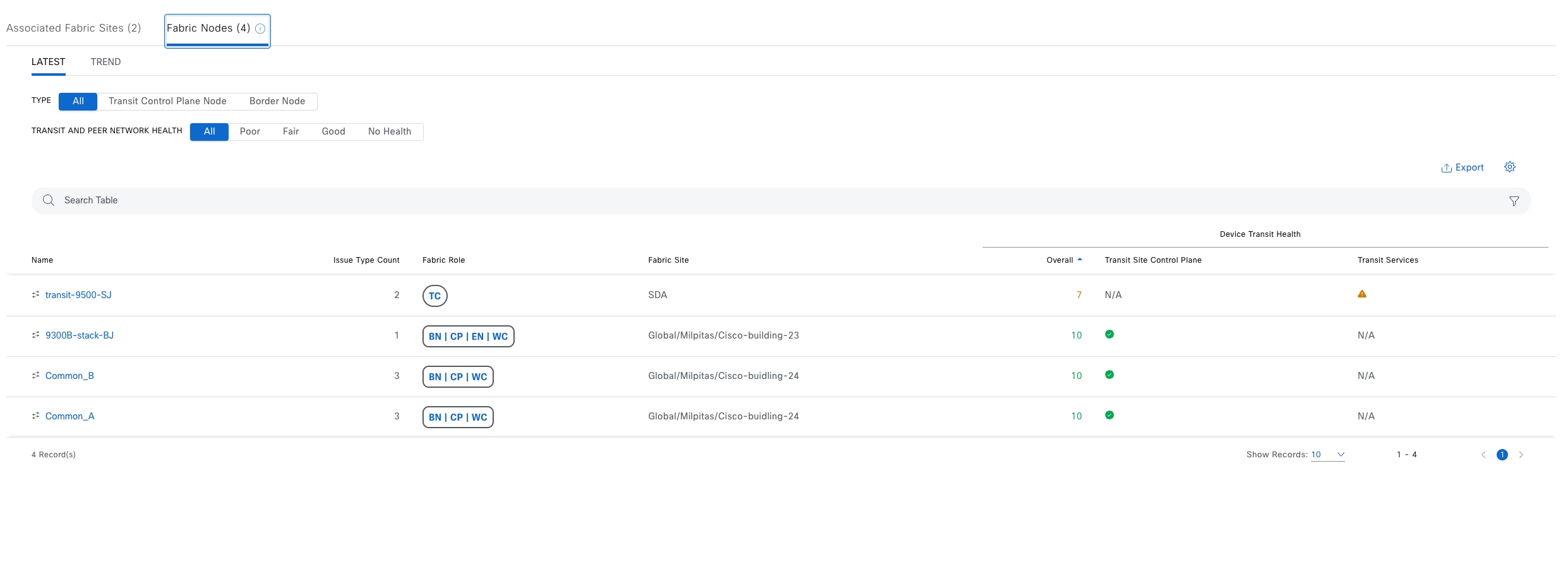
Monitor the health of devices with Device 360
Use the Device 360 window to view detailed device health information on a specific device. All the fabric devices that are provisioned and managed by Catalyst Center are monitored. Catalyst Center provides different KPIs, and information based on different fabric roles.
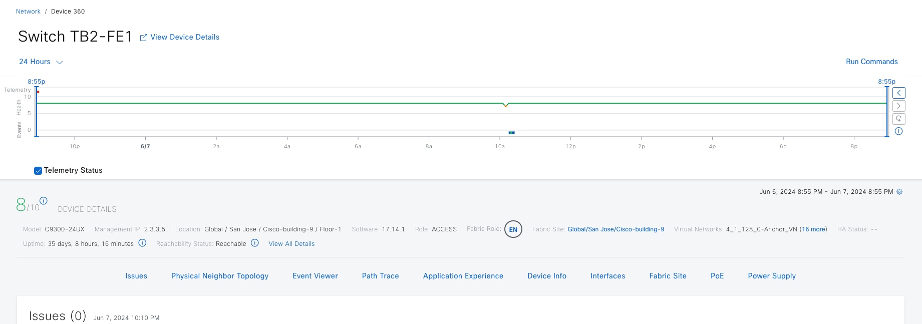
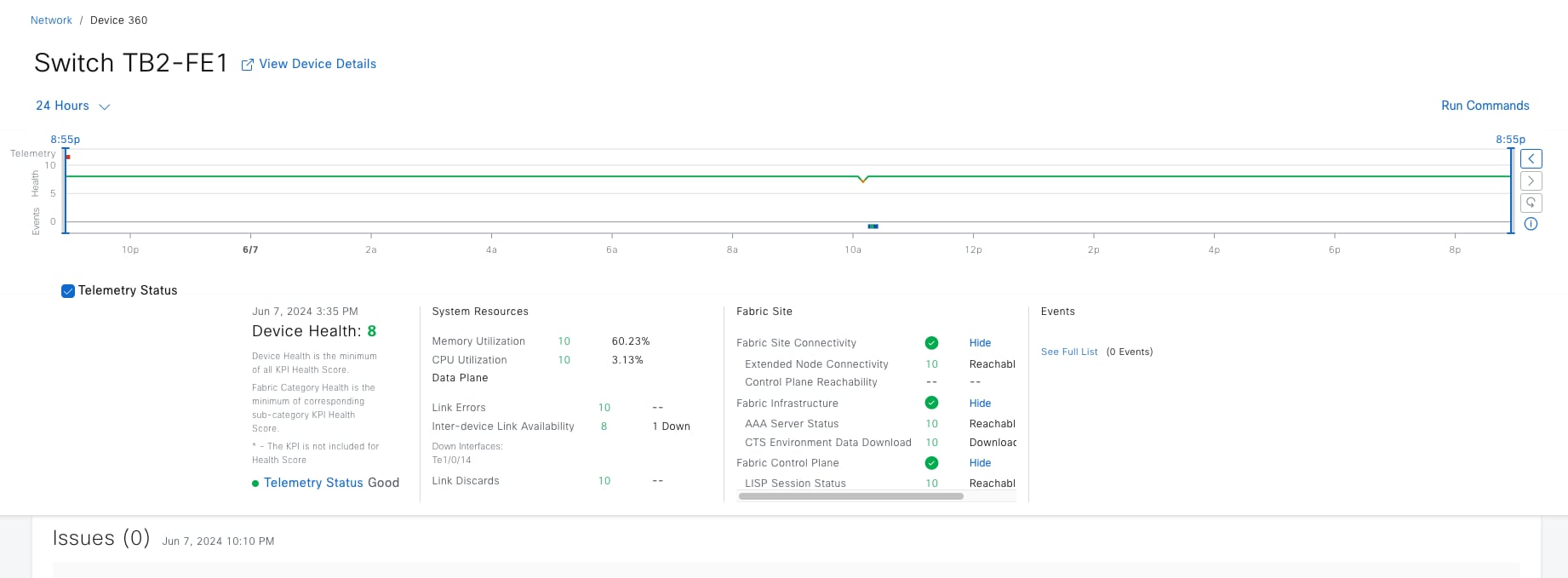
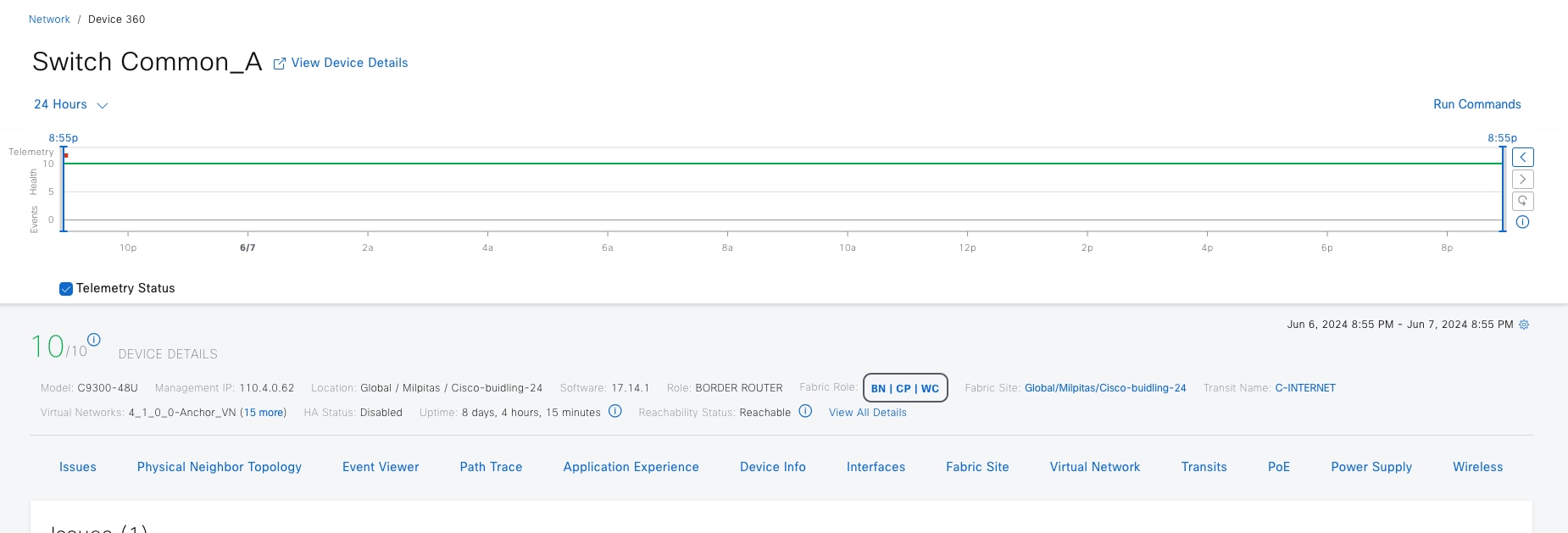
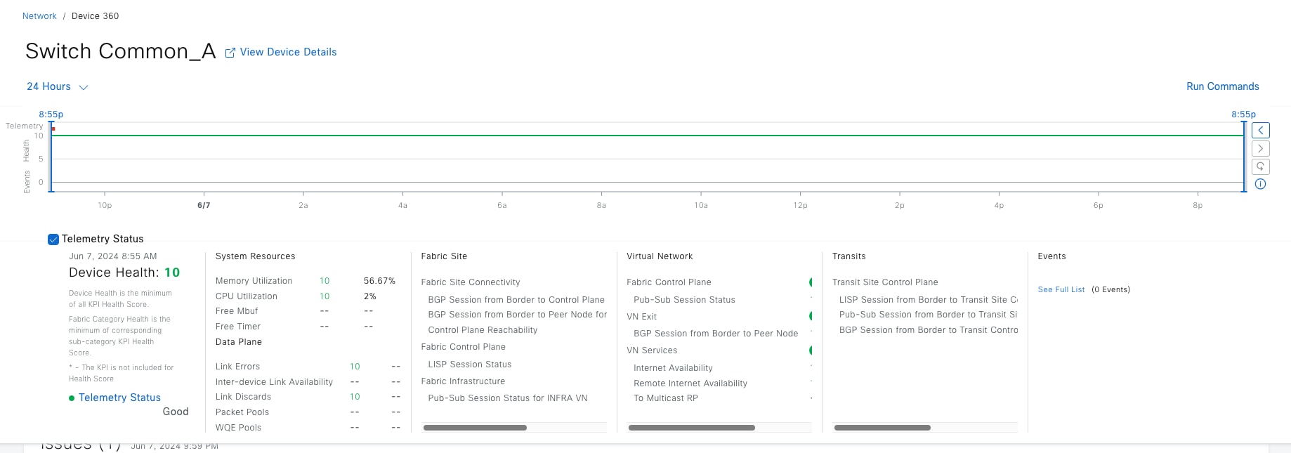
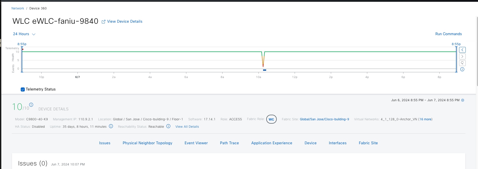
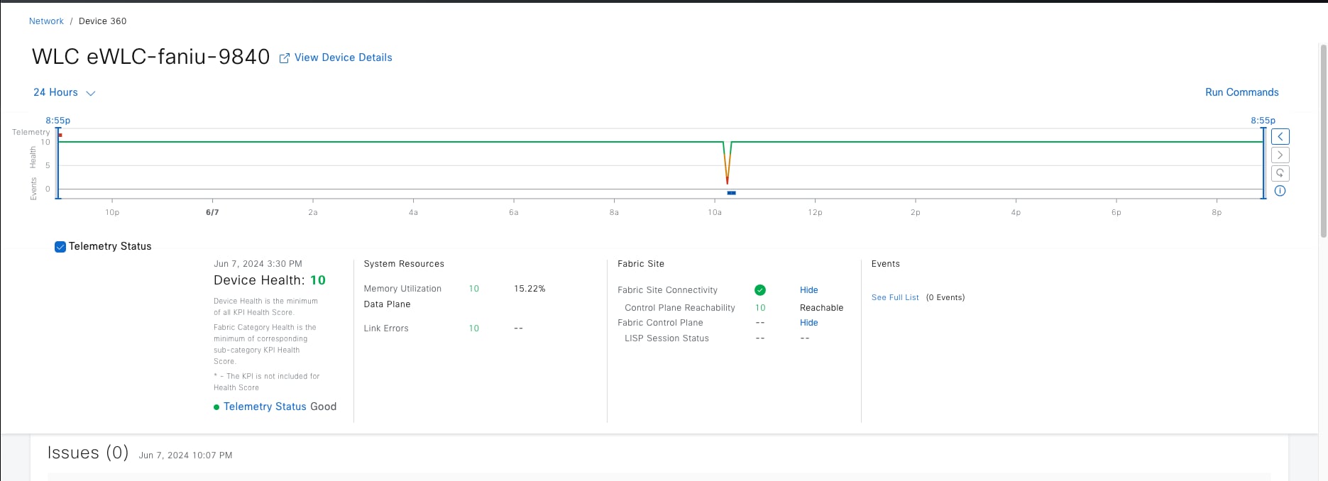
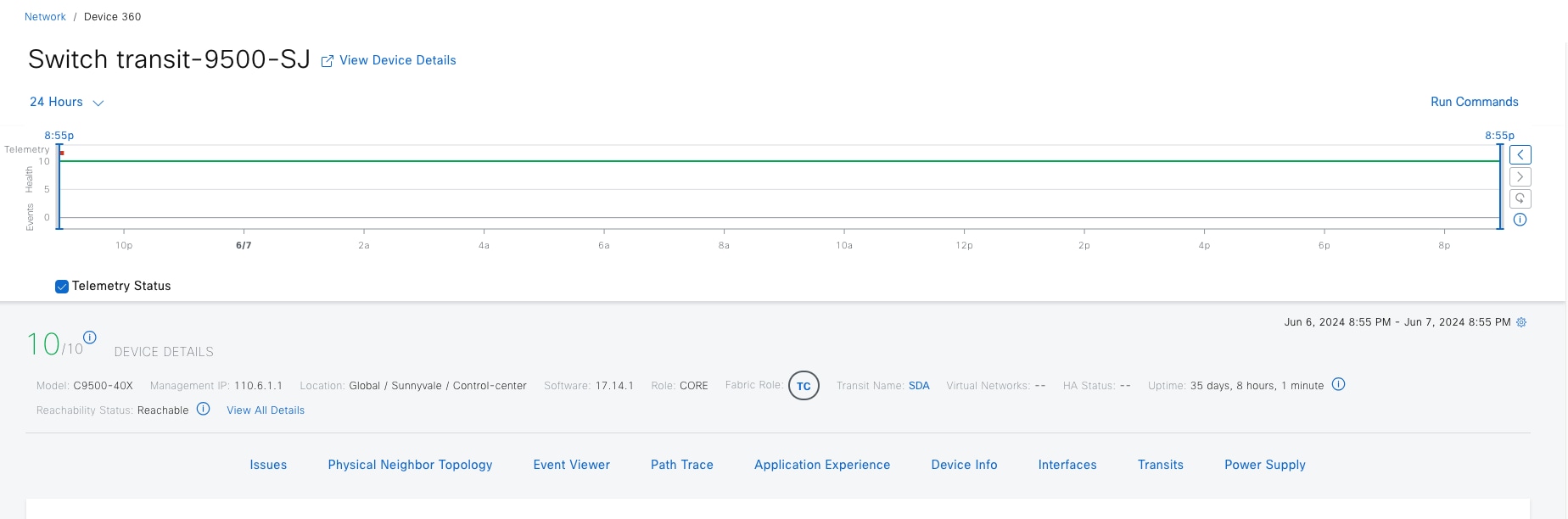
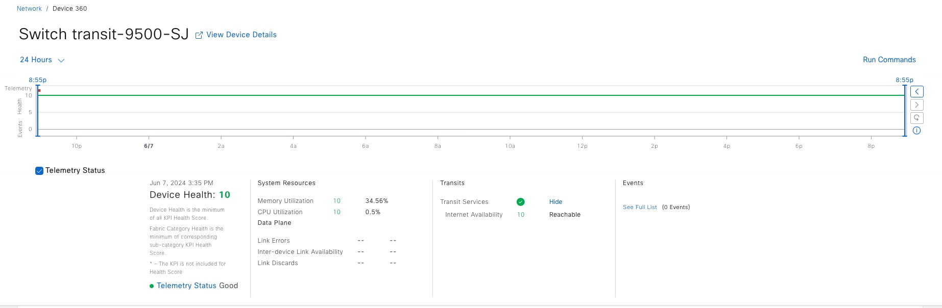
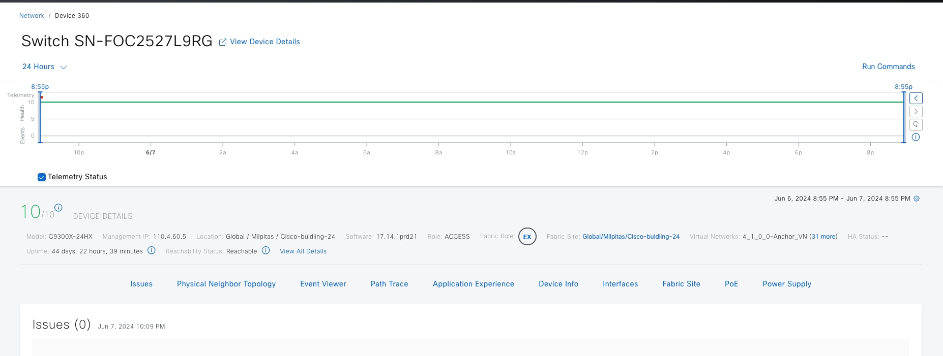
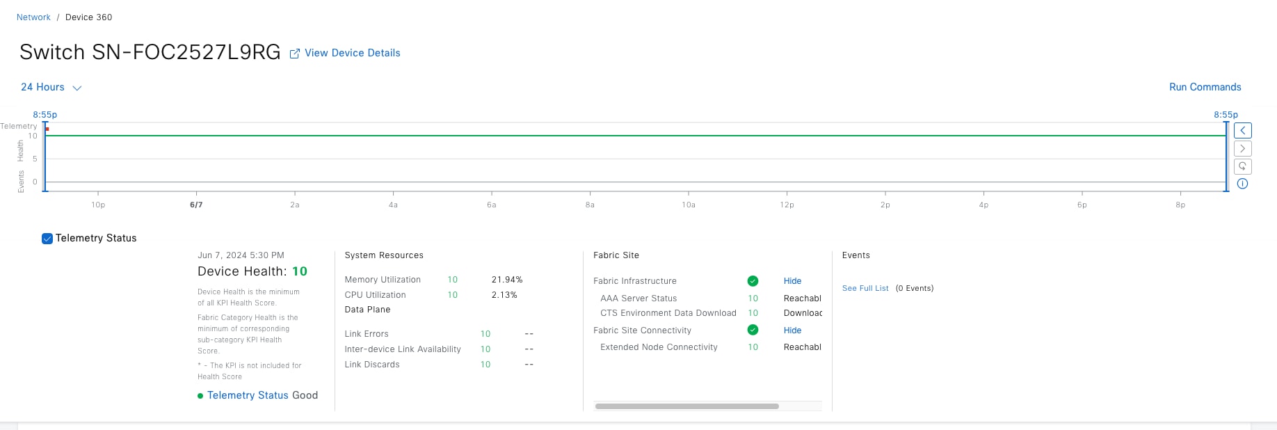
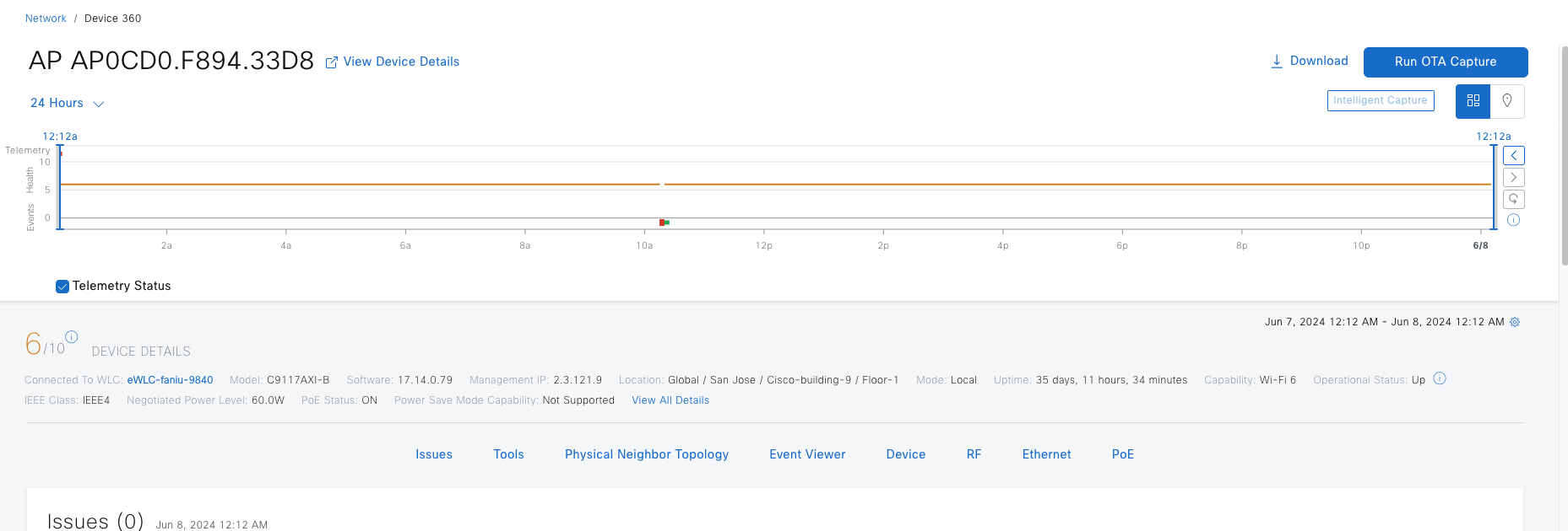
Table 26. Fabric KPIs included in the device health score
| KPI name |
Applicable Fabric Roles |
Issue Auto Resolve |
Max Latency (Issue/Health Score) |
Use |
| AAA Server Status |
Edge/EN/PEN/SBEN |
yes |
10 min/10 min |
Monitors server status for each AAA server from edge and extended nodes |
| CTS Environment Data Download |
Edge/PEN/SBEN |
yes |
10 min/10 min |
Monitors the download of CTS environment data on edge, PEN, and SBEN for the Cisco ISE Server. If AAA Server Status is down; CTS health is automatically brought down as well. |
| Extended Node Connectivity |
Edge/EN/PEN |
No |
5min/5min |
Monitors link status between extended and edge nodes on configured port channels |
| Multicast RP |
Border |
no |
10 min/10 min |
Monitors the reachability status to the external Multicast RP. |
| Control plane reachability |
wireless controller |
no |
10 min/10 min |
Monitors IPSLA reachability status from fabric wireless controller nodes to local control plane nodes. |
| LISP Session Status |
Edge/Border |
yes |
10 min/10 min |
Monitors LISP protocol sessions from border and edge nodes to local control plane nodes. |
| LISP Session from Border to Transit Site Control Plane |
Border |
yes |
10 min/10 min |
Monitors LISP protocol sessions from border nodes to connected transit control plane nodes. |
| Pub/Sub Session Status |
Border |
yes |
10 min/10 min |
Monitors Pub/Sub protocol sessions from border nodes to connected local control plane nodes for all VN, with the exception of INFRA_VN and inherited VNs for FiaB nodes. |
| Pub/Sub Session Status for INFRA_VN |
Border |
yes |
10 min/10 min |
Monitors Pub/Sub protocol sessions from border nodes to local control plane nodes for INFRA_VN. |
| Pub/Sub Session from Border to Transit Site Control Plane |
Border |
yes |
10 min/10 min |
Monitors Pub/Sub protocol sessions from border nodes to connected transit control plane nodes for all VNs. |
| Internet Availability |
Control plane
|
yes |
10 min/10 min |
Monitors default route on external borders and registers that with the control plane node within a LISP with Pub/Sub site. Monitors default route on external borders and registers that with the transit plane node within a LISP with Pub/Sub site. |
| Remote Internet Availability |
Control Plane |
yes |
10 min/10 min |
Monitors whether remote fabric sites are able to provide backup internet through SD-Access Transit connected borders within a LISP with Pub/Sub site. This KPI is not monitored if the KPI Internet Availability is already down. |
| BGP session from Border to Peer Node |
Border |
yes |
10 min/10 min |
Monitors the BGP session state from a given border node and the nonfabric peers. Sessions are tracked for all configured VNs, with the exceptions of INFRA_VN, and for both LISP/BGP and LISP with Pub/Sub protocol sites. |
| BGP session from Border to Control Plane |
Border |
yes |
10 min/10 min |
Monitors the BGP session state from a given border node to local control plane nodes for INFRA_VN only. |
| BGP session from Border to Peer Node for Infra_VN |
Border |
yes |
10 min/10 min |
Monitors the BGP session state from a given border node and the nonfabric peers. Sessions are tracked for INFRA_VN only, and for both LISP/BGP and LISP with Pub/Sub protocol sites. |
| BGP session from Border to Transit Control Plane |
Border |
yes |
10 min/10 min |
Monitor the BGP session state from a given external border node and connected transit control plane nodes. Sessions are tracked for INFRA_VN within LISP/BGP protocol sites. |
To exclude certain KPIs in the health score calculation:
Step 1. Navigate to Assurance > Setting > Health Score Settings.
Step 2. Locate and click the KPI, uncheck the Included in Device heath Score check box.
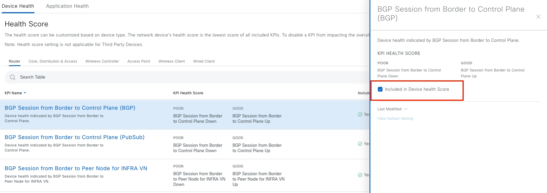
Path trace
Network admin can run a path trace between two nodes in the network—a specified source device and a specified destination device. The two nodes can be a combination of wired or wireless hosts or layer 3 interfaces or both.
When a path trace is started, the Catalyst Center reviews and collects network topology and routing data from the discovered devices. It then uses this data to calculate a path between the two hosts or layer 3 interfaces and displays the path in a path trace topology. The topology includes the path direction and the devices along the path, including their IP addresses. The display also shows the protocol of the devices along the path (Switched, STP, ECMP, Routed, Trace Route) or other source type.
Path trace has limitations and restrictions, including:
● Path trace between a fabric client and a nonfabric client is not supported.
● CDP protocol needs to be enabled on Devices.
● Path trace between two fabric clients over multiple virtual routing and forwarding (VRF) virtual networks (VNs) is not supported.
● Path trace from a router's loopback interface is not supported.
● Overlapping IP addresses are not supported with or without fabric.
● Path trace on a Locator ID/Separation Protocol (LISP) fabric requires the traffic to be running, and the cache to be available on the edge switches.
● Path trace in Cisco Adaptive Security Appliances (ASA) is not supported because Cisco ASA does not support CDP. It is not possible to identify the path through the Cisco ASA appliance.
● Path trace is not supported for the management interface in wireless controllers in untagged mode.
● Path trace for Virtual Switching System (VSS), Multi-Link Aggregation Control Protocol (MLACP), or Virtual Port Channel (vPC) is not supported.
● Path trace for Equal-Cost Multi-Path Routing (ECMP) over Switched Virtual Interface (SVI) is not supported.
● Path trace is not supported on devices with NAT or firewall.
● Path trace from a host in a Hot Standby Router Protocol (HSRP) VLAN to a host in a non-HSRP VLAN that is connected to any of the HSRP routers is not supported.
● Port-channel Port Aggregation Protocol (PAgP) mode is not supported. Only LACP mode is supported.
● Path trace for wireless clients that use OTT in a Cisco SD-Access fabric is not supported.
● Path trace from a layer 2 switch is not supported.
● Cisco Industrial Ethernet (IE) switches are extended nodes as part of the Cisco SD-Access solution. Currently, path trace does not recognize extended nodes, so if a topology contains extended nodes, an error message displays.
● Dual stack with both IPv4 and IPv6 addresses for devices is not supported. If this occurs, an error message displays stating that the given address is unknown.
Path trace can be run from the Client 360 window and Device 360 window. This example shows the start path trace from a client named lily.
Step 1. From the menu icon button, choose Assurance > Health then click the Client tab.
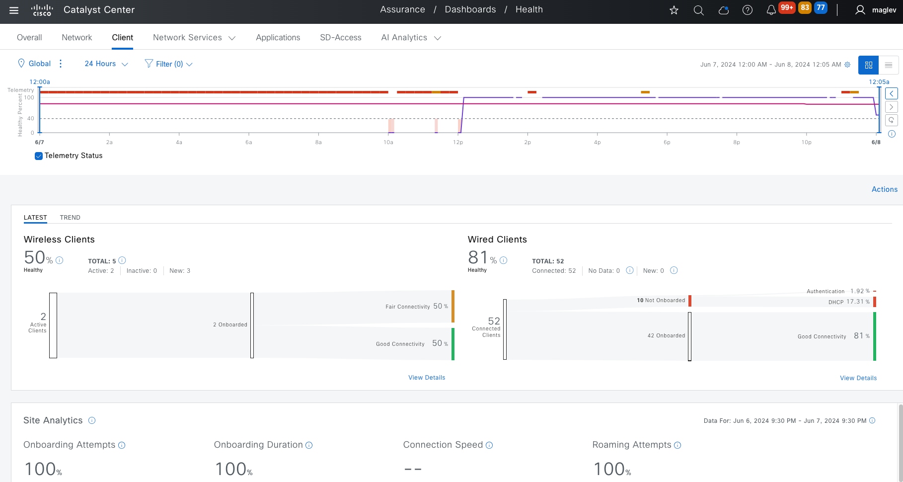
Step 2. Locate and check the client lily check box.
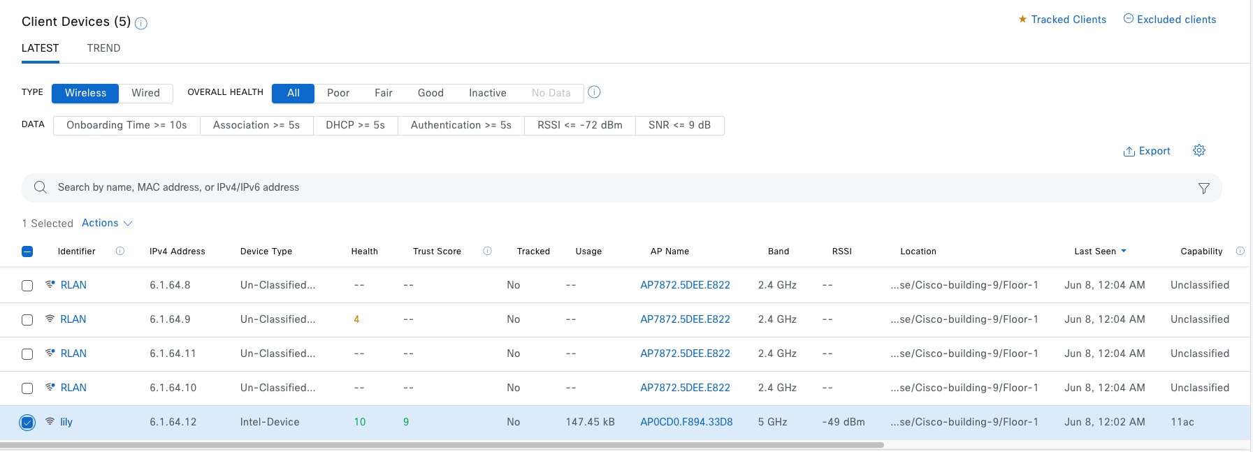
Step 3. Scroll down in the redirected Client 360 window to the Tools section then click Run New Path Trace.
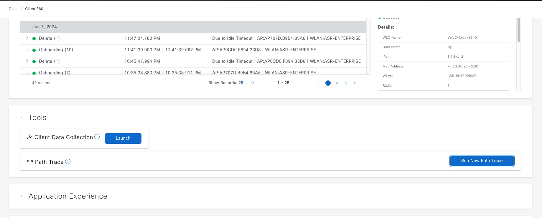
Step 4. Enter the mandatory field. The Destination field is for a wired client with IP 6.1.0.9 then click Start.
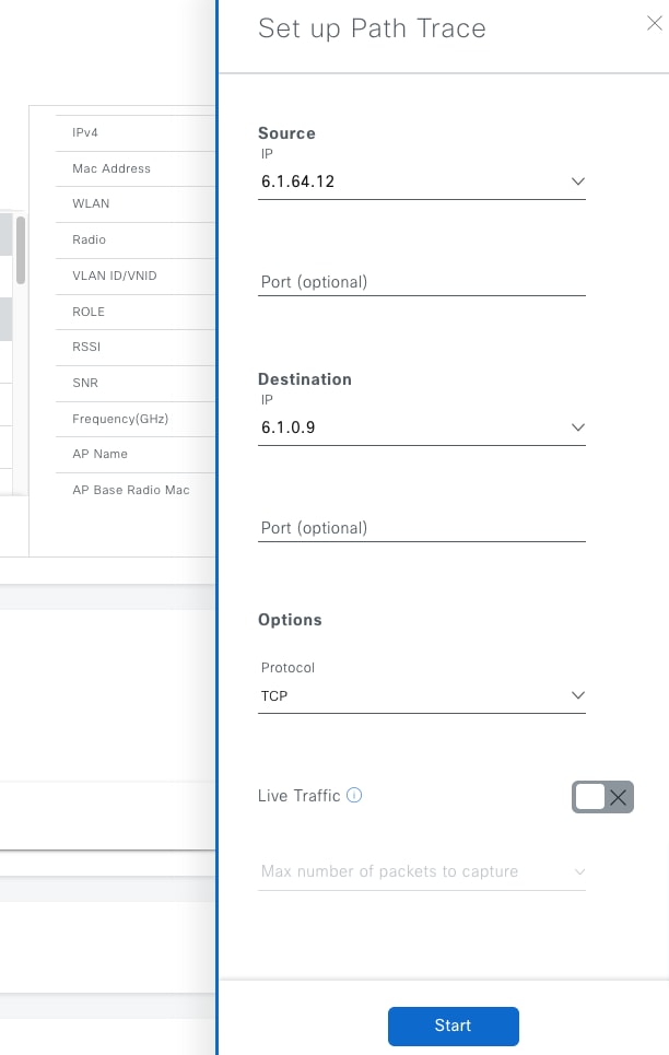
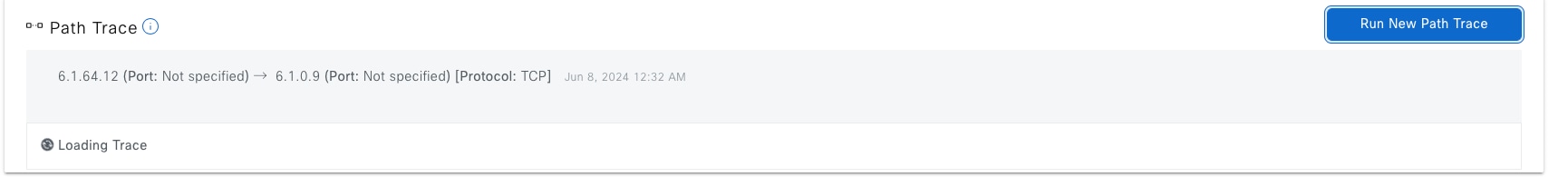
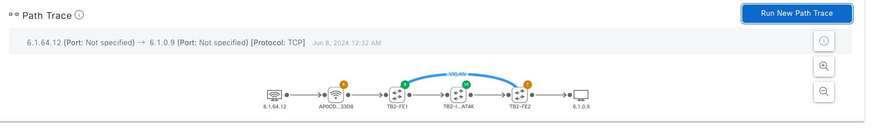
Catalyst Center provides system validation tool to help network admin monitor Cisco SD-Access application health. The tool checks every 15 minutes automatically for any database data inconsistency in a Cisco SD-Access application. The check can also be run manually.
To check the results:
Step 1. From the top-left corner, click the menu icon and choose System > System 360.
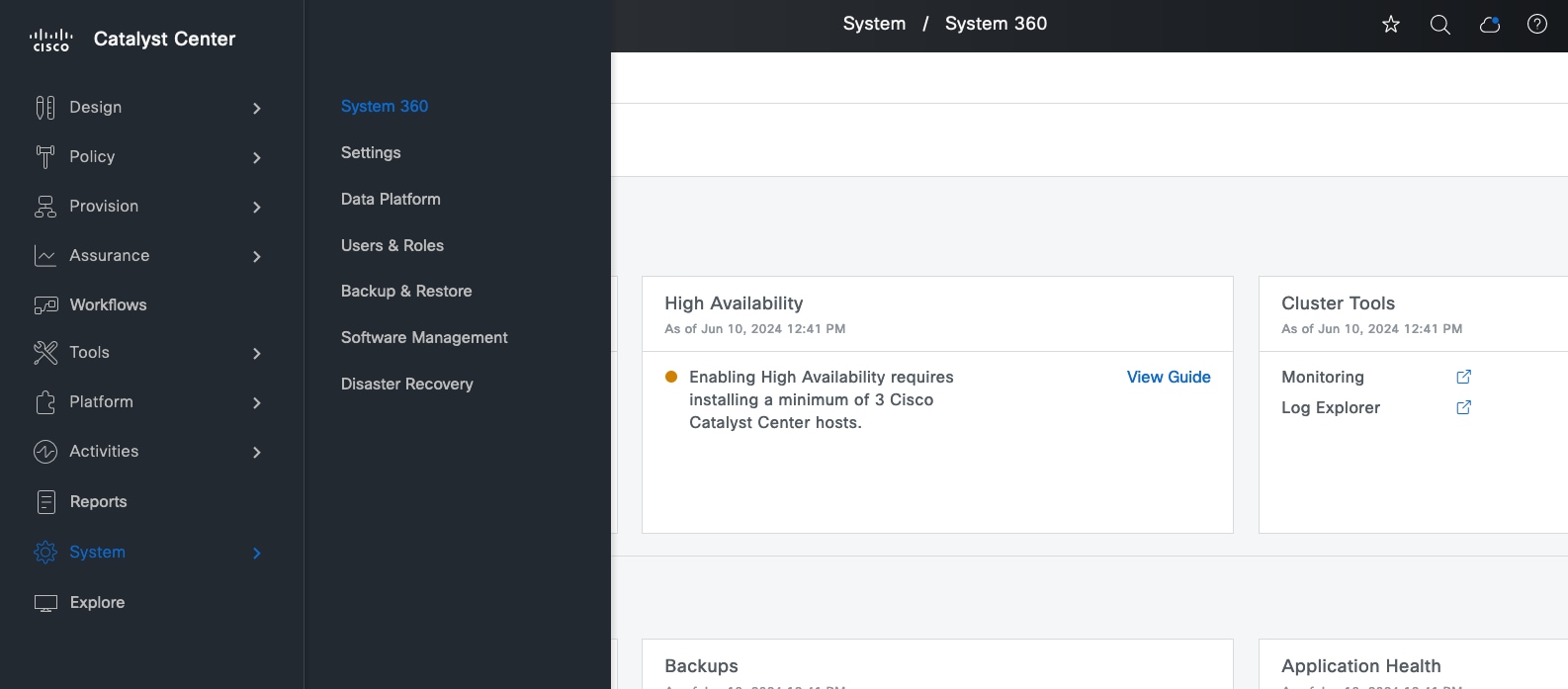
Step 2. On the landing window, click the System Health tab. This window shows if there are any system level failures or warnings.
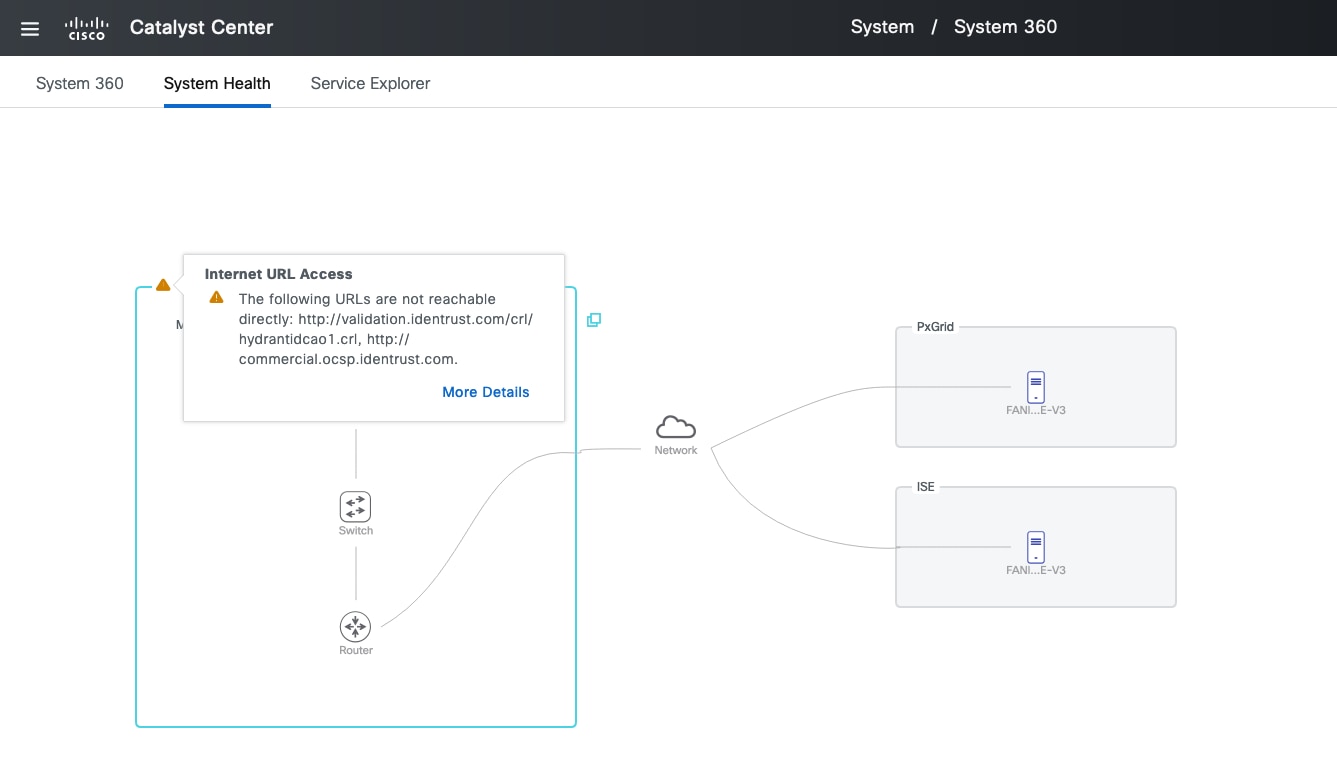
To manually run a check:
Step 1. Click Tools > Validation Tool.
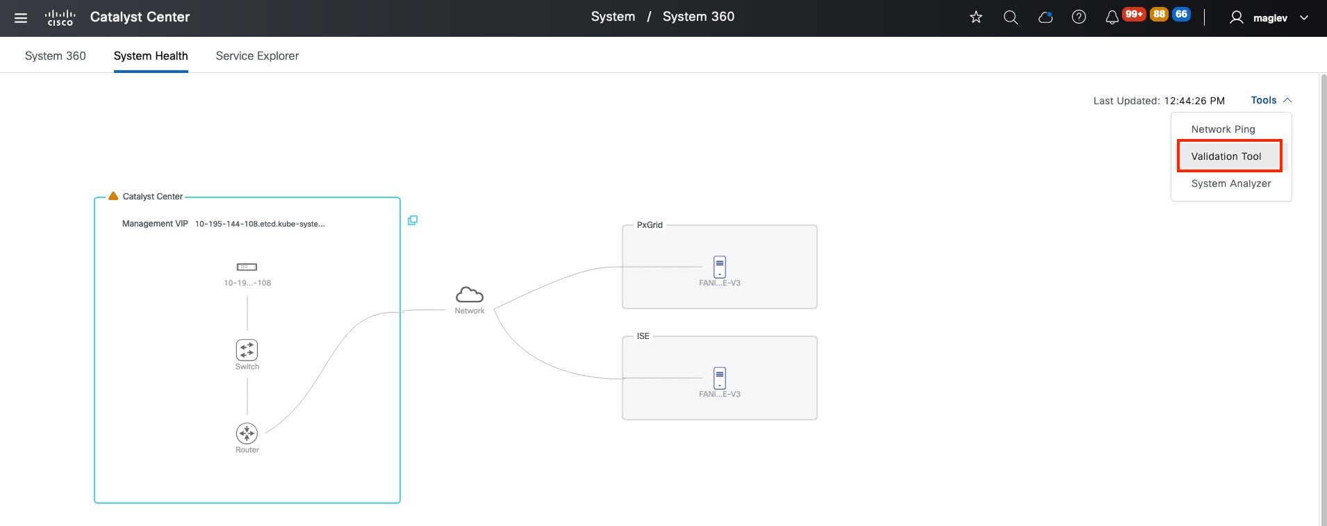
Step 2. In the Validation Tool window, click Add then on the slide in pane, check the Application Heath Status check box for Cisco SD-Access.
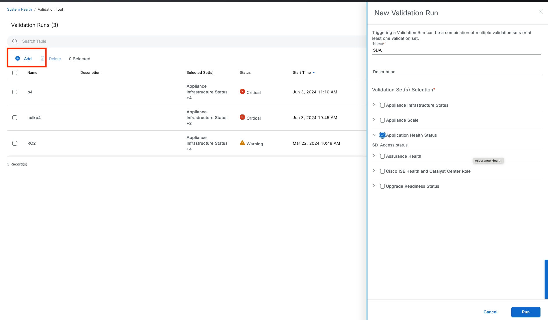
If there is a failure, SD-Access status reports a DEGRADED message.
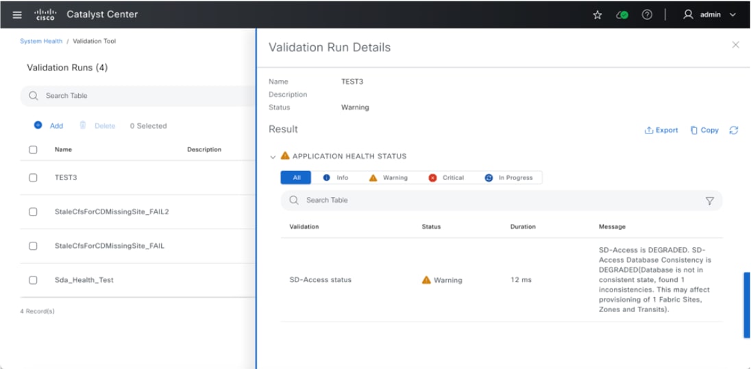
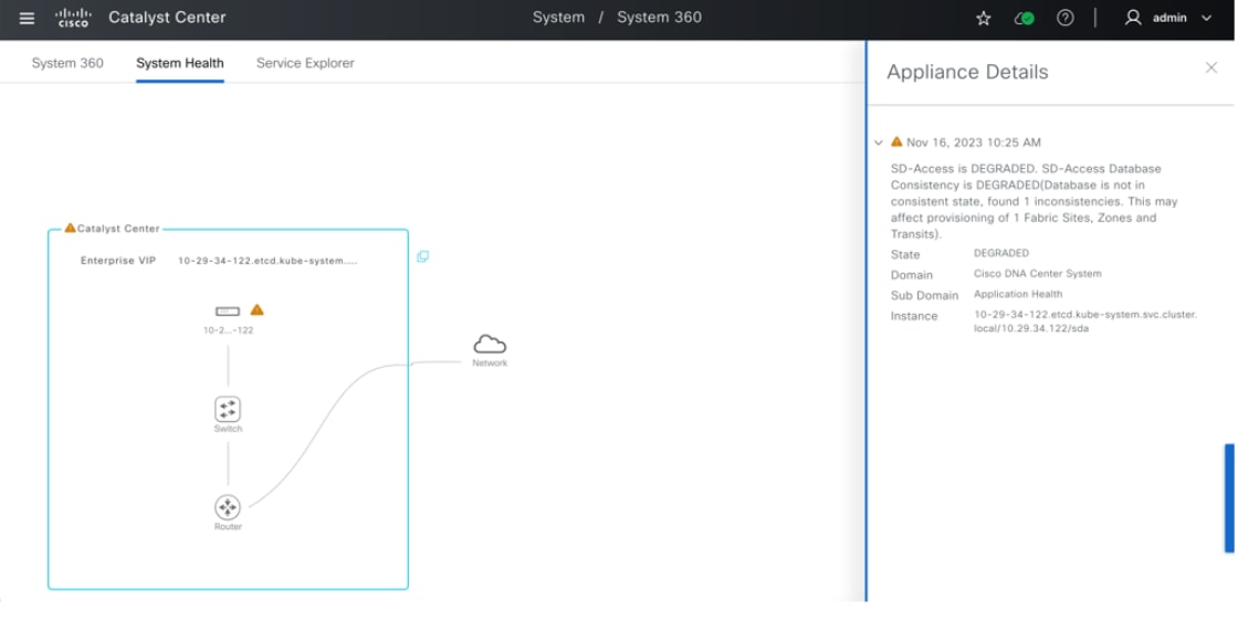
Step 3. Check the System Health window after an upgrade and in daily operations. If Cisco SD-Access reports a DEGRADED message, contact Cisco TAC support.
Cisco SD-Access Compatibility Matrix
Catalyst Center maintains Cisco SD-Access Compatibility Matrix compliance for software image versions on managed devices during Cisco SD-Access role provisioning.
On startup of the Catalyst Center Provision service, a scheduler is set up to run every 24 hours to trigger a task to download the latest available file from Cisco using a pre-defined link. If there is no new file, the download task is skipped. A download task can be triggered if there is a version released.
For air gap customers, a download task always fails. The latest file must be downloaded and then the new file must be uploaded through the UI. The same manual uploading is required for clusters without reachability to Cisco.
If a device is running incompatible software or the device is not supported in Cisco SD-Access, Catalyst Center blocks the ability to add this device into fabric with roles for Border, Control plane, Edge, Extended Node (PnP auto-onboarding), and wireless controller. The enforcement is enabled by default in Catalyst Center in 2.3.7.5 and later releases and can be disabled.
To upload a new Compatibility Matrix file or disable the enforcement:
Step 1. From the top-left corner, click the menu icon and click System > Settings.
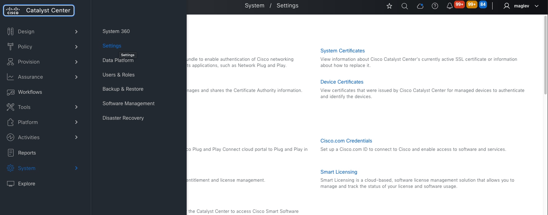
Step 2. Click External Services > SD-Access Compatibility Matrix to go to the landing window.
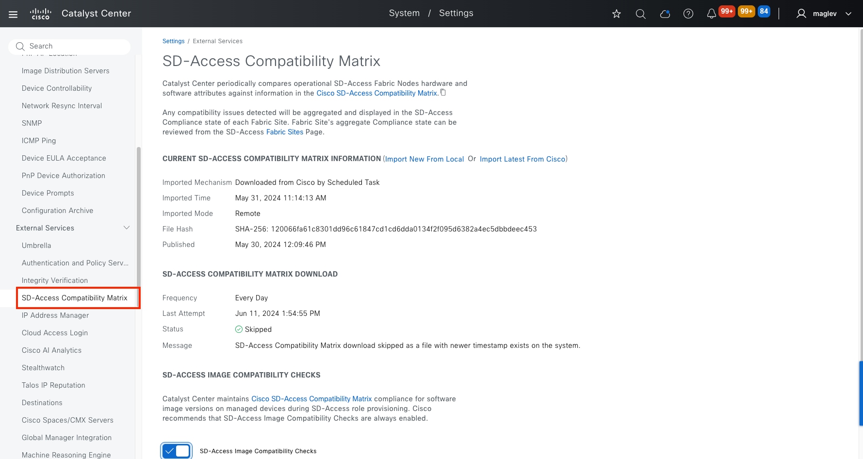
● To upload a new compatibility matrix file, click Import New From Local.
● For a new download, click Import Latest from Cisco.
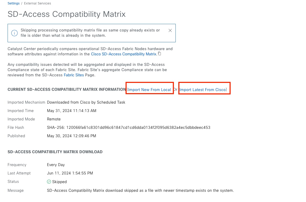
● To disable the enforcement, scroll down to the bottom of the window, disable SD-Access Image Compatibility Checks.
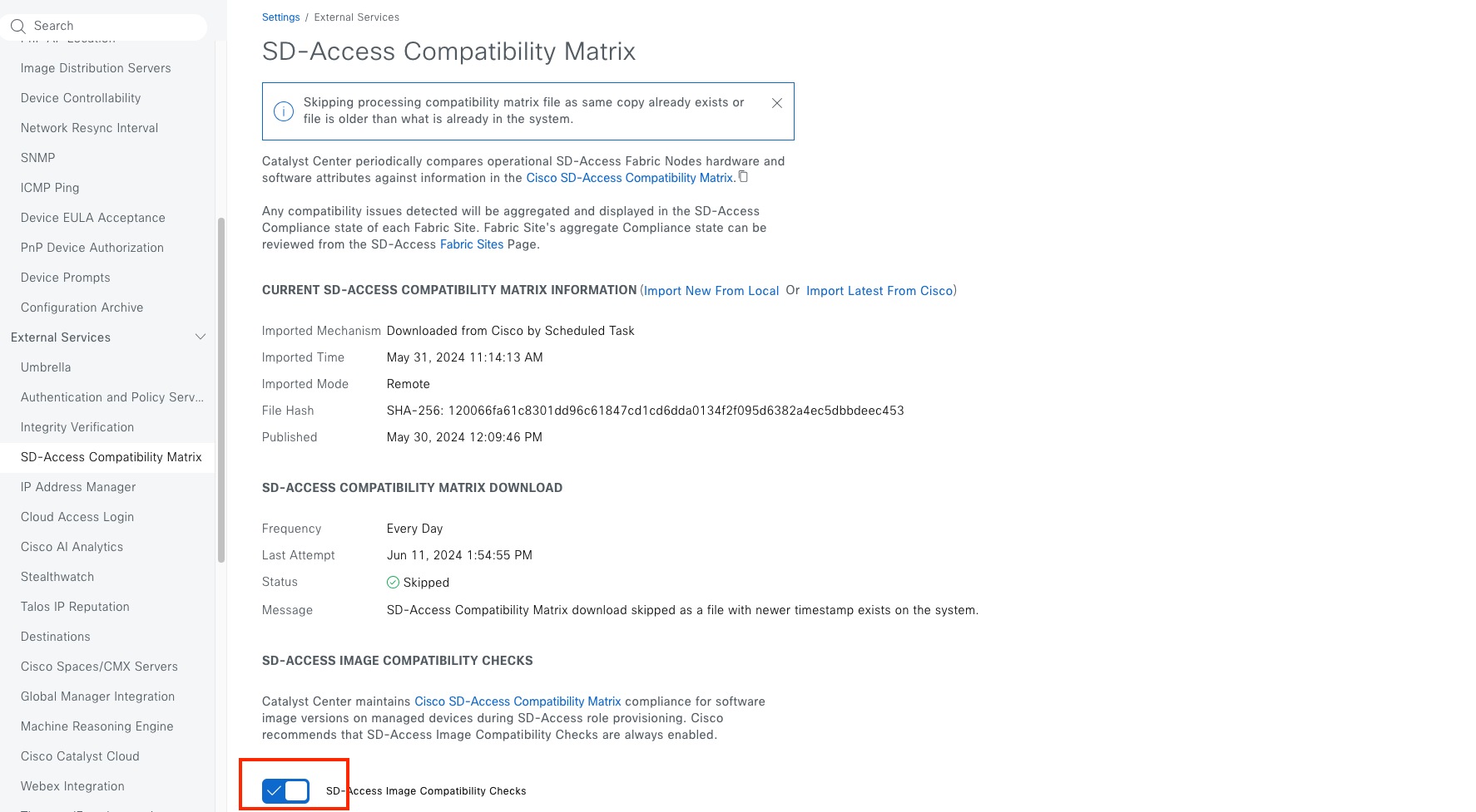
Tech tip: Keep SD-Access Image Compatibility Checks enabled.
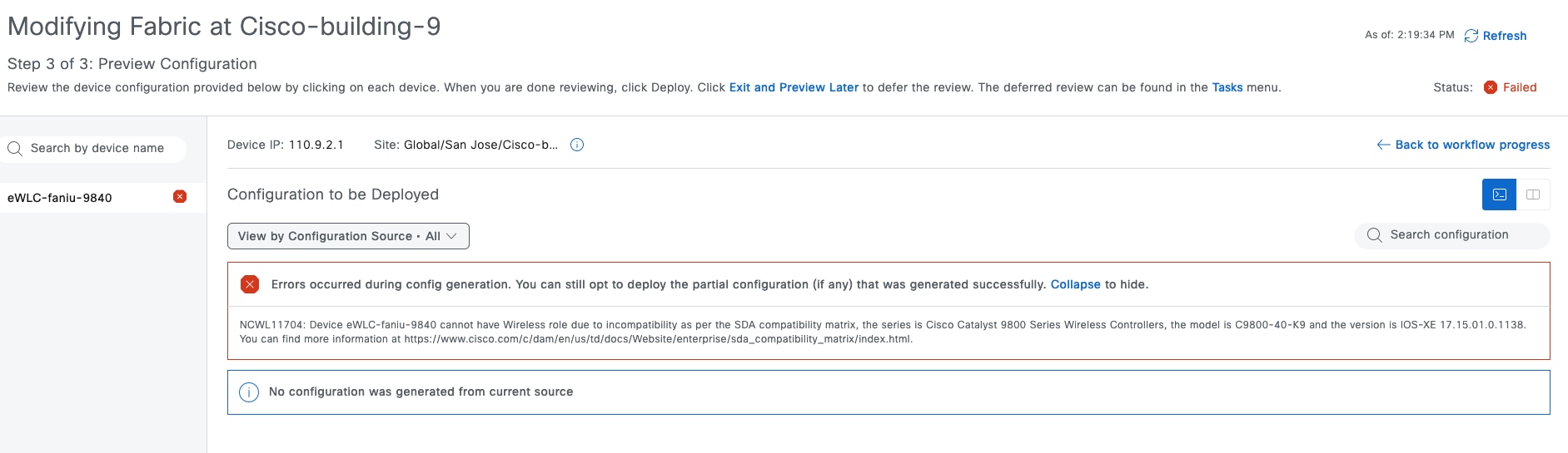
Appendix
Appendix A—Hardware and software used for validation
This design and deployment guide was created using the hardware and software listed in this table:
Table 27. Hardware and software
| Functional area |
Product |
Software version |
| Standalone Wireless LAN Controllers |
Cisco Catalyst 9800-40 wireless controllers |
17.15.1 |
| Embedded Wireless Controller on Catalyst 9000 |
Embedded Wireless Controller on Cisco Catalyst 9300 |
17.15.1 |
| Colocated Fabric Border and Control Plane |
Cisco Catalyst 9300 |
17.15.1 |
| Fabric Edge |
Cisco Catalyst 9300 |
17.15.1 |
| Policy extended Node and Supplicant-based extended node |
Catalyst 9300 and Catalyst 9200 |
17.15.1 |
| Enterprise SDN Controller |
Catalyst Center |
2.3.7.x |
| AAA Server |
Cisco Identity Services Engine (ISE) |
3.3 |
Appendix B—Glossary
AP Access Point
Cisco ISE Cisco Identity Service Engine
CDP Cisco Discovery Protocol
CMD Cisco Meta Data
CTS Cisco TrustSec
CUWN Cisco Unified Wireless Network
DS Distribution System
EID Endpoint’s Identity
GRT Global Routing Table
HA High Availability
MSRB Multisite Remote Border
PSN Policy Service Node
RF Radio Frequency
OTT Over the Top
pxGrid Platform Exchange Grid
REST APIs Representational State Transfer Application Programming Interfaces
RLOC Routing Locator
SD-Access Cisco Software Defined Access
SGACL Security Group ACL
SGT Security Group Tag
SSID Service Set Identifier
SSO Stateful Switch-over
SXP SGT Exchange Protocol
SVI Switched Virtual Interface
VN Virtual Network
VNI VXLAN network identifier
VRF Virtual Routing and Forwarding
VXLAN Virtual Extensible LAN
WLAN Wireless Local Area Network
WLC Wireless LAN Controller
Appendix C—Reference
Catalyst Center 2.3.7.x Third-Generation Installation Guide
Cisco Software-Defined Access Compatibility Matrix
Catalyst Center 2.3.7.x Data Sheet
Policy Platform Capability Matrix
Catalyst Center 2.3.7.x User Guide
Catalyst Center SD-Access LAN Automation Deployment Guide
SD-Access Solution Design Guide