Scalable and Resilient Enterprise Edge Architecture
Available Languages
Bias-Free Language
The documentation set for this product strives to use bias-free language. For the purposes of this documentation set, bias-free is defined as language that does not imply discrimination based on age, disability, gender, racial identity, ethnic identity, sexual orientation, socioeconomic status, and intersectionality. Exceptions may be present in the documentation due to language that is hardcoded in the user interfaces of the product software, language used based on RFP documentation, or language that is used by a referenced third-party product. Learn more about how Cisco is using Inclusive Language.
- US/Canada 800-553-2447
- Worldwide Support Phone Numbers
- All Tools
 Feedback
 Feedback
Enterprise networks are carrying larger internet routing tables, more encrypted traffic, and more direct connections to public cloud services than many legacy designs were built to support. As organizations adopt AI workloads, including agent-based applications, they must also account for growing bandwidth demands and the movement of large data volumes across campuses, data centers, and cloud environments. At the same time, they need consistent segmentation and identity context across these environments, while enabling local internet access and security enforcement at campus and branch edges where appropriate.
This white paper presents a reference architecture for modernizing Cisco ASR 1000 Series aggregation, interconnect, and edge deployments with Cisco 8400, 8500, and 8600 Series Secure Routers. It describes five deployment roles: Internet Edge, Colocation and Cloud Gateway, Campus WAN Edge, SD-WAN Aggregation, and MPLS VPN Aggregation. A common router family, with role-specific hardware and feature support, provides a path to preserve existing network services while addressing capacity, resiliency, security, segmentation, cryptographic migration, management, and assurance needs.
Long-lived sensitive data raises additional cryptographic considerations: encrypted traffic captured today could be retained for future decryption if the public-key methods used to establish or authenticate connections become vulnerable. Preparing for post-quantum cryptography is therefore a consideration for organizations that need to protect data over extended periods. Separately, AI-driven vulnerability discovery, including research such as Anthropic’s Mythos, highlights the potential for shorter timelines between identifying software weaknesses and developing exploits. This increases the value of rapid mitigation while permanent fixes are prepared and deployed.
The paper is intended for enterprise network architects and engineers evaluating or planning an ASR 1000 modernization. It describes design roles and operating considerations; it is not a configuration guide or deployment plan. Capability availability and behavior vary by router model, software release, operating mode, protocol, peer support, and management integration. Validate capacity and implementation details against current Cisco product documentation and any applicable Cisco Validated Design for the selected environment.
Enterprise edge network architecture
Enterprise networks connect sites, campuses, data centers, colocation facilities, and cloud environments, each with different traffic patterns, trust boundaries, scale requirements, and availability needs. Routing, segmentation, encryption, and traffic inspection are placed where the design requires them. What matters is the role each part of the network performs, the trust boundary it protects, and the failure domain it must withstand.
This paper organizes the architecture around those roles. Traffic moves from sites across one or more transports, through aggregation points, and toward internet services, cloud workloads, or other enterprise locations. The five roles covered are Internet Edge, Colocation and Cloud Gateway, Campus WAN Edge, SD-WAN Aggregation, and MPLS VPN Aggregation.
The Case for an ASR 1000 refresh architecture
For enterprise infrastructure teams, an ASR 1000 refresh is more than a hardware replacement. It is a chance to revisit how each Edge and Aggregation role is designed.
While the established routing topology, addressing schemas, and existing Cisco IOS XE feature sets are fully preserved without requiring a disruptive network redesign, modernizing with the Cisco 8000 Series Secure Routers fundamentally transforms the operational posture surrounding each role by decoupling software lifecycle management, closing the cryptographic vulnerability window against emerging quantum threats, and extending actionable observability beyond the physical device.
Five architectural shifts distinguish this platform family from a conventional box replacement:
● Unified Management and Correlated Assurance: Cisco Cloud Control and Cisco ThousandEyes bring together unified inventory, synchronized cross-domain topology views, and native on-box telemetry. Together, they provide correlated observability and a single operational view across the network.
● Runtime Vulnerability Mitigation (Live Protect): On an ASR 1000, addressing high-severity Common Vulnerabilities and Exposures (CVEs) often requires an in-service software upgrade (ISSU) or a disruptive reload. Live Protect applies microcode-level vulnerability shields at runtime while the router forwards traffic, removing the forced choice between an unplanned outage and prolonged exposure.
● Protect traffic in transit with PQC architecture. Use IPsec for overlays across transports the enterprise does not control. Use MACsec on supported point-to-point links when both endpoints and the connection type support it. The Cisco 8000 Series Secure Routers introduce hybrid post-quantum key establishment to protect long-lived sensitive data over public and private transports.
● Resiliency Through Independent Failure Domains. Use independent nodes, diverse links, failure detection, and routing convergence where the role requires them. Set a capacity objective for the surviving system after a failure.
● Predictable Scale and Dimensioning: Forwarding performance, routing table depth, stateful NAT session limits, and crypto tunnel capacities are sized deliberately to accommodate current production loads and sustained organic traffic growth across each architectural boundary.
This architectural transition is accelerated by distributed artificial intelligence and machine learning workloads, where high-throughput dataset transfers, continuous model training synchronization between private data centers and public cloud VPCs, retrieval-augmented generation (RAG) queries, and real-time agent-to-agent inference APIs generate sustained elephant flows that quickly saturate legacy forwarding queues and CPU-bound classification engines.
The high-end Cisco 8000 Series Secure routers pair high-density 40GE and 100GE interfaces and deep buffers with hardware application classification. This lets large AI data transfers move through the network without crowding out latency-sensitive traffic or weakening perimeter security. See Cisco 8000 Series Secure Routers.
Technology building blocks of the architecture
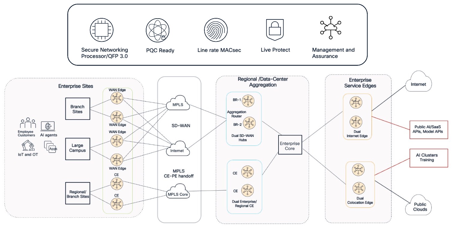
The architecture is supported by five technology layers. The Secure Networking Processor and QFP 3.0 form the routing and encryption foundation. Post quantum readiness and MACsec protect traffic at the tunnel and physical link layers, while Live Protect provides runtime vulnerability mitigation. Cisco Cloud Control and ThousandEyes add management and assurance capabilities, giving teams visibility and operational control across the network.
Layer 1: Custom silicon foundations
The Cisco 8000 Series Secure Routers portfolio leverages two purpose-built custom silicon engines, aligning hardware acceleration directly with deployment scale:
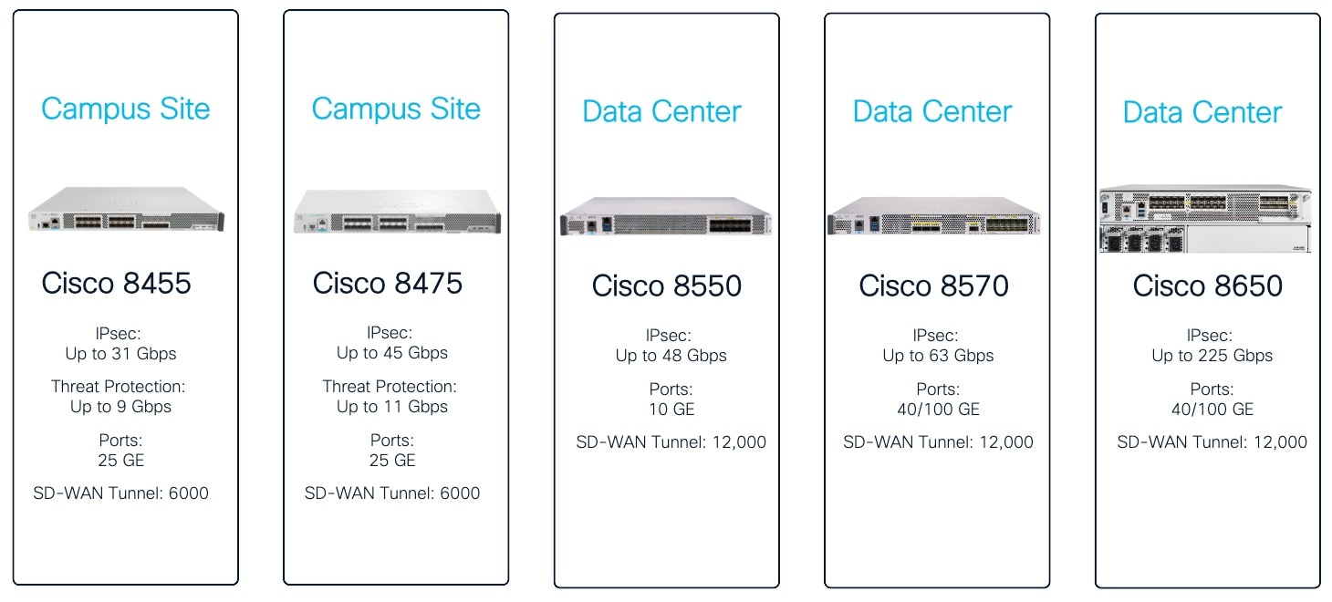
Secure networking processor (SNP): Deployed across campus edge and branch platforms such as the Cisco 8400 Series Secure Routers, the SNP is an integrated System-on-Chip (SoC) combining Layer 3 forwarding, an on-chip firewall data path, and an inline hardware encryption engine. The SNP processes crypto and routing concurrently within the same pipeline, supporting up to 91 Gbps of forwarding and up to 45 Gbps of IPsec throughput (at 512B) on the C8475-G2 with 25GE interfaces
● QuantumFlow processor 3.0 (QFP 3.0): Deployed on regional aggregation, colocation, and internet edge platforms, including the Cisco 8500 Series Secure Routers and Cisco 8600 Series Secure Routers, QFP 3.0 represents a generational evolution over the first- and second-generation QFP engines found in ASR 1000 ESPs (such as the ESP40, ESP100, and ESP200). While the ASR 1000 ESPs provided robust performance for traditional enterprise routing, the QFP 3.0 introduces dedicated microcode-level hardware acceleration to sustain up to 16 million IPv4/IPv6 routes, up to 32 million stateful Carrier-Grade NAT (CGNAT) sessions and forwarding and IPsec crypto capacities scaling up to 540 Gbps and 225 Gbps respectively on the high-end platform like C8650-G2.
Layer 2: Post-quantum cryptography
As cryptographic standards evolve to address future quantum computing capabilities, the Cisco 8000 Series introduces hybrid ML-KEM key exchange to proactively secure long-lived corporate data against emerging threats. See PQC on Cisco 8000 Series Secure Routers.
● Hybrid key establishment: Incorporates Module-Lattice Key Encapsulation Mechanism (ML-KEM, standardized under FIPS 203), establishing session keys by combining classical ECDH with ML-KEM so that an adversary must break both schemes to compromise the payload.
● Quantum-safe by design: Hybrid ML-KEM key exchange extends to IKEv2/IPsec overlays, administrative SSH management sessions, and Layer 2 MACsec Key Agreement (MKA) starting in Cisco IOS XE 26.1.1
● Controlled transition: Flexible proposals allow aggregation hubs to negotiate with both existing ASR 1000 endpoints and modern PQC-enabled devices concurrently, enabling migration without requiring a flash cutover.
Layer 3: Line-rate MACsec
MACsec on the ASR 1000 routers depends on specific interface modules. The Cisco 8000 Series Secure Routers joins the wider Cisco enterprise portfolio to establish an uninterrupted, hop-by-hop Layer 2 encryption fabric spanning from the wireless edge all the way to cloud interconnects.
● Campus-to-cloud encryption continuum: With Cisco supporting MACsec on Cisco Catalyst 9100 Access Points to secure physical Ethernet drops running through ceilings and open spaces into the wiring closet, and Cisco Catalyst 9000 Series switches protecting inter-switch links and distribution risers, the Cisco 8000 Series Secure Routers complete this security perimeter by extending line-rate MACsec across campus border handoffs, carrier CE-to-PE transport circuits, and high-speed colocation cross-connects (such as AWS Direct Connect and Azure ExpressRoute).
● Zero forwarding degradation: Across the Cisco 8400, 8500, and 8600 Series, 128-bit and 256-bit WAN and LAN MACsec (IEEE 802.1AE) is embedded directly into physical-layer framing silicon across built-in front-panel interfaces, encrypting and decrypting frames at the physical layer without consuming packet processing cycles, which eliminates the need for separate throughput sizing exercises and makes link encryption the viable default across every physical handoff.
Layer 4: Runtime vulnerability mitigation (Cisco Live Protect)
On the ASR 1000, as on most routers , fixing a high-severity vulnerability means a software upgrade and maintenance window.
Cisco Live Protect on Cisco 8000 Series Secure Routers enables operations teams to apply targeted runtime Cisco Vulnerability Shields directly to the active forwarding data path to neutralize exploitation attempts while the router continues forwarding production traffic, allowing operators to audit shield telemetry in monitor mode, transition to enforce mode, and schedule permanent software upgrades during normal, planned maintenance intervals. See Cisco Live Protect on Cisco Secure Routers and Cisco Catalyst SD-WAN Monitor and Maintain Configuration Guide.
Layer 5: Unified operations and embedded assurance
The Cisco 8000 Series Secure Router architecture consolidates operations and visibility through unified cloud management and integrated active telemetry:
● Cisco Cloud Control operations: Integrates cross-domain inventory, synchronized end-to-end topology views, and correlated incident alarms across Catalyst SD-WAN Manager, Catalyst Center, and Security Cloud Control into a single operational interface that simplifies lifecycle management and eliminates policy drift. See Cisco Cloud Control.
● On-box ThousandEyes traffic insights: The Cisco ThousandEyes Enterprise Agent operates natively as an embedded container within the router's application framework, ingesting streaming Flexible NetFlow records (including 5-tuples, DSCP markings, and granular NBAR application classifications) and correlating internal conversation flows with active synthetic path measurements to immediately detect micro-burst congestion and QoS priority inversions that remain hidden within standard 5-minute SNMP polling windows. See Traffic Insights on Cisco Secure Routers.
● ThousandEyes BGP monitoring With BGP running on Cisco Secure Routers at the enterprise edge, ThousandEyes can help teams monitor route announcements and changes alongside network and application performance. Enterprise Agent measurements provide visibility from selected points in the network, helping operations teams see whether a route change is affecting reachability, latency, or packet loss and assess whether traffic engineering is working as intended. See BGP monitoring with ThousandEyes.
AI-ready throughput and application qualification
Enterprise traffic profiles have evolved beyond predictable client-server patterns into distributed AI architectures, where massive dataset ingestions, model training synchronizations between data centers and public cloud VPCs, real-time retrieval-augmented generation (RAG) queries, and low-latency agent-to-agent inference calls create high-throughput bursts across enterprise aggregation and edge boundaries.
Bursty data transfers of such high volume can saturate single-chassis ESP pipelines and shallow interface queues, resulting in buffer bloat, micro-burst packet drops, and unpredictable latency variations that degraded concurrent business applications. Concurrently, classifying these workloads can be constrained by software-based NBAR2 engines running inside CPU microcode. Enterprise network design has moved from picking a product for each location to designing for each boundary. Historically, teams deployed one product family for branch routing, another for data center aggregation, and a third for internet peering. That approach created separate management silos, inconsistent security policies, and different cryptographic standards across the enterprise. In this architecture, the design starts from the functional boundary, and the hardware model follows from it
The Cisco 8000 Series Secure Routers addresses both challenges through an integrated, hardware-accelerated data path designed specifically for modern and AI-driven workloads:
● Deep-buffer throughput and non-blocking interfaces: High-density 40GE and 100GE physical handoffs pair with deep-buffer queue architectures and multi-hundred-gigabit forwarding capacity (up to 540 Gbps forwarding and 225 Gbps IPsec crypto on the C8650-G2) to sustain massive AI data synchronizations and concurrent inter-cloud transfers without introducing packet jitter or starving latency-sensitive traffic across the WAN.
● Line-rate application qualification and policy enforcement: Classification logic in the router silicon identifies applications at line rate. It can recognize specific SaaS applications, API services, and AI agent traffic, not only broad protocol types. The router can then apply the right QoS queue, SD-WAN path, and selective on-box firewall inspection to each flow.
Outcomes of the architecture
Across the enterprise edge and aggregation roles, the refresh delivers measurable results in capacity, cryptography, protection, and operations compared with current ASR 1000 deployments.
By providing dedicated, hardware-accelerated pipeline processing, the architecture allows network teams to accurately dimension capacity for concurrent services, such as high-bandwidth IPsec, Carrier-Grade NAT, and full internet routing tables without the forwarding degradation typically experienced on shared ESP microcode.
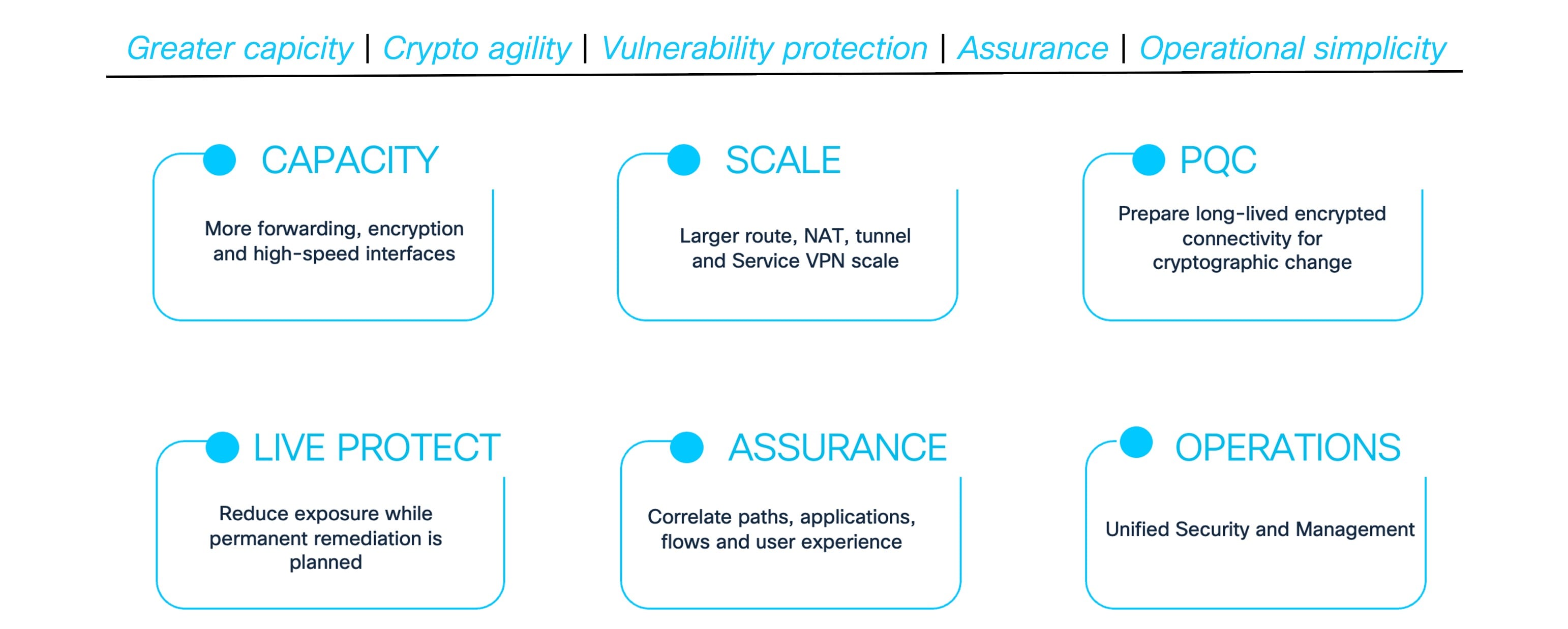
This predictable scale is paired with proactive cryptographic agility, establishing a unified migration path to hybrid post-quantum cryptography (incorporating NIST FIPS 203 ML-KEM) to close the "Harvest Now, Decrypt Later" exposure window across all public and private transports. Operationally, the platform fundamentally changes security lifecycle management through Live Protect, which applies targeted runtime Vulnerability Shields directly to the active data path, neutralizing high-severity CVEs without requiring emergency device reboots.
To ensure continuous digital experience, the platform embeds the Cisco ThousandEyes Enterprise Agent directly on the router, correlating internal application flow metrics with active synthetic path tests and external global BGP intelligence to instantly isolate performance anomalies across the LAN, upstream ISPs, or public clouds. Ultimately, standardizing on Cisco IOS XE Software under Cisco Cloud Control across all edge and aggregation roles establishes a single operational framework, unifying inventory visibility, YANG automation pipelines, and engineering skill sets across the entire enterprise estate.
Architecture by network role
Enterprise network design has moved from picking a product for each location to designing for each boundary. Historically, teams deployed one product family for branch routing, another for data center aggregation, and a third for internet peering. That approach created separate management silos, inconsistent security policies, and different cryptographic standards across the enterprise. In this architecture, the design starts from the functional boundary, and the hardware model follows from it.
A common router family provides a consistent forwarding and operational foundation across these roles. Each role still has its own traffic profile, routing relationships, security controls, scale requirements, and failure domain. An internet edge, a private cloud interconnect, a campus WAN boundary, an SD-WAN headend, and an MPLS VPN aggregation point connect different network domains and enforce different boundaries. Defining these responsibilities makes it possible to use a common platform while keeping routing, segmentation, policy, and operational ownership clear.
The five roles describe the principal points where the enterprise connects its sites to the internet, cloud services, campus, SD-WAN fabric, and private WAN. An organization can adopt each role independently or combine several roles as part of a broader architecture. Figure 4 shows how the roles relate and how traffic passes between them.
| Architectural Role |
Technical Function and Design Scope |
Deployment Location |
| Internet Edge |
Connects the enterprise to internet service providers and peers. It applies external route controls, address translation, and edge traffic protections. Extranet and partner connectivity can be provided through isolated patterns within this role. |
Data center or carrier-neutral colocation facility, facing upstream service providers and internet exchanges. |
| Colocation and Cloud Gateway |
Terminates high-throughput private cross-connects (e.g., AWS Direct Connect, Azure ExpressRoute) into multiple public cloud environments. Applies line-rate MACsec over physical cross-connects, optional post-quantum ready IPsec overlays, and strict outbound BGP filtering to isolate VRFs and prevent the enterprise from inadvertently acting as a transit autonomous system between competing cloud providers. |
Colocation or interconnect facility, beside the enterprise core. |
| Campus WAN Edge |
Connects campus switching and segmentation domains to WAN and internet transports. It preserves identity-based micro-segmentation context (mapping campus Security Group Tags to WAN service VPNs), terminates mixed transports (MPLS, Cellular, LEO Satellite), and performs on-box next-generation firewall inspection for direct internet access (DIA) traffic without forcing regional backhaul. |
Campus site, above the campus switching fabric. |
| SD-WAN Aggregation |
Terminates branch and campus SD-WAN overlays at regional or data center hubs. It applies tunnel, service VPN, application-aware routing, and segmentation policy at scale. |
Enterprise data centers or centralized regional transit hubs |
| MPLS VPN Aggregation |
Connects enterprise sites and regional aggregation through MPLS Layer 3 VPN services. It defines customer edge and provider edge responsibilities, VRF separation, VPN route distribution, and the handoff to the core. The provider edge manages MP BGP route targets and distinguishers to enforce strict multi-tenant isolation across the core while providing a segment routing ready transport foundation with a defined evolutionary path to SRv6. |
Regional aggregation points or data centers, facing the private enterprise WAN core. |
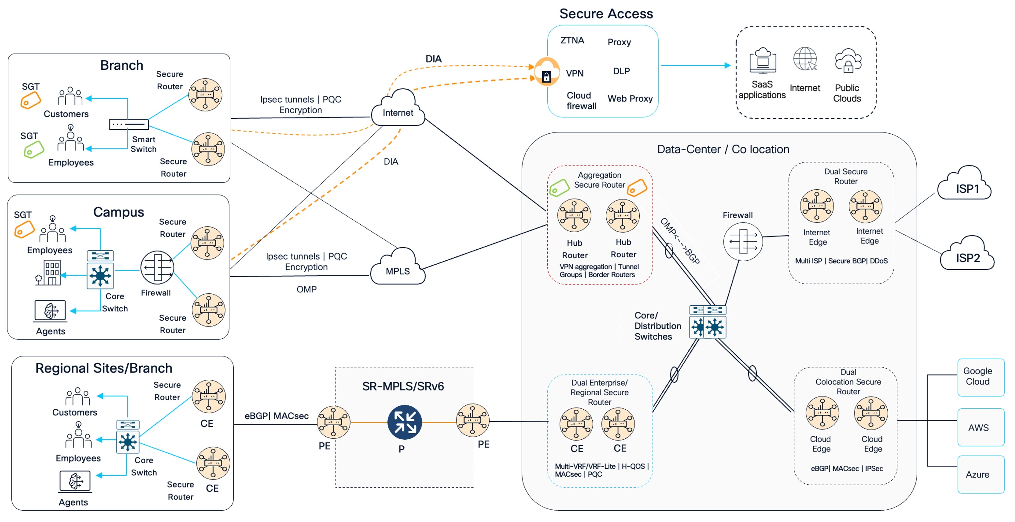
The architecture is best understood by tracing the flow of traffic from left to right, beginning at the distributed enterprise edge. The architecture begins at the branch, campus, and regional sites shown on the left. At each location, customers, employees, and AI agents connect through the local switching or Campus Network while maintaining the separation of traffic using micro or macro segmentation. Dual secure routers are deployed at each location to provide device redundancy, with connectivity arranged so that the loss of one router does not remove the site’s only path into the network.
Branch and campus traffic can reach the rest of the enterprise through the SD-WAN overlay. The overlay can use internet or MPLS connectivity as its underlying transport, while IPsec protects traffic across the tunnels. Through SD-WAN controllers, OMP distributes overlay routes and policy information in control plane so that the SD-WAN routers know which destinations are reachable through each headend or site. The overlay carries traffic for enterprise applications and other destinations that policy directs through the SD-WAN hubs.
Internet-bound traffic has another possible path. Where direct internet access is enabled, a branch or campus can send that traffic out locally toward Cisco Secure Access. The cloud-delivered service can apply the relevant internet and application security policies, such as secure web access, data loss prevention, or zero trust access to private applications. This path can suit users and applications that benefit from local breakout and cloud-delivered security. If policy instead requires centralized inspection or egress, the traffic can travel across the overlay to the data center and leave through the enterprise internet edge. See Cisco Secure Access overview.
The regional sites at the lower left also show a private MPLS VPN path. Their customer edge routers connect to provider edge routers using external BGP, with MACsec protecting supported physical links. The provider edge routers carry the private VPN traffic across the service provider core, which the figure represents as an SR-MPLS or SRv6 network. This gives the enterprise a routed private WAN path that can carry site traffic toward regional aggregation and the data center. It is distinct from the SD-WAN overlay, although MPLS can also serve as an underlay transport for SD-WAN tunnels where the design calls for it.
At the center of Figure 4, the data center or colocation facility brings the network roles together. The SD-WAN hub routers terminate overlay tunnels from branch and campus locations and exchange approved routes with the enterprise network. Once inside the facility, traffic does not flow directly from the Aggregation routers to the outside world. Instead, it traverses a robust internal infrastructure layer comprising core distribution switches, centralized Cisco Secure Firewalls, and traffic load balancers. This intermediate layer acts as the primary traffic director, applying deep packet inspection, enforcing centralized enterprise security policies, and intelligently steering flows toward the appropriate external egress gateway based on the specific destination of the payload.
The firewall enforces security policy on the traffic paths assigned to it, and an application load balancer can be placed in the path to services that require traffic distribution across multiple application servers. The placement of these services depends on the application and its security requirements.
Traffic destined for public internet services can leave through the redundant internet edge routers, which connect to multiple service providers and apply the configured routing controls and protections.
Traffic for private workloads in Google Cloud, AWS, or Azure can use the cloud gateway routers, which terminate the cloud connections and exchange the required routes with each provider. The private cloud path is appropriate when the enterprise has provisioned private connectivity to those workloads. Public SaaS applications or public cloud endpoints can instead use local Secure Access or the centralized internet edge, depending on the route and security policy.
The Figure 4 shows how the architecture keeps user and application traffic segmented at the sites, provides redundant routers and multiple transport choices, and brings those paths to clearly defined service boundaries in the data center or colocation facility. The internet edge handles general internet connectivity, while the cloud gateway handles private connectivity to cloud workloads. The SD-WAN hubs and the private MPLS VPN provide separate ways to reach enterprise destinations, with the core, firewall, and optional load balancer connecting those paths to the applications that use them.
In the data center/colocation, the label “OMP to BGP” should be read as controlled route exchange between the SD-WAN overlay and the enterprise routing domain. OMP and BGP do not form a direct routing adjacency with each other. The actual redistribution point, route filters, and import and export policy should be identified in the detailed design.
Resiliency and high availability in the architecture
Enterprise aggregation and edge roles carry externally facing and inter-site traffic, and in many designs, they consolidate functions that were previously distributed across many smaller systems. Consolidation improves cost, density, and operational consistency, but it also concentrates traffic onto fewer systems. The availability model must therefore be designed deliberately: the objective is that the loss of any single element, whether a link, a line card, a node or a control plane, degrades capacity without interrupting service.
This architecture delivers availability through redundant, independent nodes per role, with fast failure detection and routing convergence between them.
Node-level redundancy model
In this reference architecture, Aggregation and Edge roles use two or more independently operating Secure Routers. The routers have separate chassis, backplanes, and control planes. Power feeds, switching, cabling, and provider paths are diversified where the site design allows. The redundant nodes are sized to maintain the required service after a node failure.
| Design element |
Description |
| Active/Active where the role allows |
Internet edge, Aggregation, and Colocation designs can use both nodes to carry traffic. After a node failure, traffic can move to the surviving node. |
| Fast failure detection |
BFD can detect forwarding path failures in less than a second when enabled on supported adjacencies and configured with suitable negotiated timers. Routing and forwarding recovery depend on the selected protocol and available alternate paths |
| Fast convergence |
TI LFA can provide precomputed repair paths in supported segment routing underlays. BGP PIC can switch to a preinstalled alternate path in supported IP and MPLS VPN designs. Fast Reroute provides sub second convergence on SD-WAN hub or branch router. |
| N + 1 capacity planning |
Size the surviving node or nodes to carry the required traffic after a single failure, using the actual service mix and service objectives. Validate the design under the expected encryption, QoS, routing, and traffic profile. |
Where a role requires more than two nodes, N+1 means that the required service load is carried by N nodes and one additional independent node or equivalent capacity remains available after a single failure. The capacity objective, traffic distribution, stateful-service behavior, and restoration procedure should be validated per role.
How each network role changes with refresh
Refreshing an ASR 1000 deployment is not a mere hardware substitution, but a fundamental modernization of the enterprise boundary.
These are established network functions that ASR 1000 routers already perform. Refreshing them with Cisco 8000 Series Secure Routers increases available throughput and expands the scale at which routing, encryption, application policy, and security inspection can operate together.
Refresh also introduces capabilities entirely absent from the legacy generation, such as post-quantum cryptography (PQC) and Live Protect runtime vulnerability mitigation.
| Role |
In the ASR 1000 deployment today |
What the refresh changes |
| Internet Edge |
A high-end ASR 1000 can connect to multiple ISPs and Internet exchanges through eBGP, carry full or partial IPv4 and IPv6 routing tables, and apply route filters and edge protections such as FlowSpec. With an ESP200 or ESP200-X, the platform is rated for up to 200 Gbps forwarding with 8.5M IPv4 routes with RP3.
|
The C8650 refresh uses a 4x QFP3 architecture across the router pair with up to 540Gbps forwarding and supports multi 10/40/100GE Internet peering, 16 million IPv4 and IPv6 routes, and 32 million NAT sessions per router. Dedicated provider handoffs are natively encrypted with line rate WAN and LAN MACsec alongside post quantum cryptography ready IPsec overlays. Furthermore, ThousandEyes Traffic Insights adds correlation between router flow records, application classification, and synthetic test results and Live Protect runtime shields neutralize platform vulnerabilities without service disruption. |
| Colocation and Cloud Gateway |
The ASR 1000 can provide the Layer 3 gateway for colocation and cloud connectivity. It can use eBGP to exchange approved prefixes with cloud or service provider gateways over supported private connections. Where end-to-end network layer encryption is required, IPsec tunnels can be built between the enterprise and cloud gateway endpoints. |
High-end C8650-G2 Secure Router retains eBGP route exchange and IPsec overlay options while providing higher forwarding and encryption capacity for the gateway role. It supports up to 540 Gbps forwarding and up to 225 Gbps IPsec throughput at 512-byte packets, with 10/40/100GE ports and 16 million IPv4 and IPv6 routes. Physical cross-connects are secured with line-rate MACsec, while overlays utilize hybrid post-quantum IPsec (ML-KEM) in hardware. WAN and LAN MACsec are supported on all built in ports, allowing link encryption on a compatible provider cross connect, subject to support at the provider handoff. Quick failure detection combined with BGP Prefix Independent Convergence provides sub second failover, SD-WAN overlay can extend directly into public cloud environments, and Live Protect applies runtime vulnerability shields without rebooting routers. |
| Campus WAN edge |
An ASR 1000 pair provides routed connectivity between campus buildings, the enterprise WAN, branch locations and external services, using dynamic routing, VRFs, QoS, IPsec, NAT and traffic visibility features such as NetFlow and application classification. Depending on the model and configuration, an ASR 1000 can also provide zone-based stateful firewall inspection at the WAN boundary. This is distinct from a modern integrated threat protection service. |
The C8400 is designed for campus edge deployments and combines routing, and hardware accelerated threat protection on one platform. The C8475-G2 provides up to 91 Gbps forwarding, 45 Gbps IPsec and 11 Gbps threat protection. The refresh adds integrated NGFW threat protection, MACsec on all built in ports, and post quantum cryptography capabilities in C8400. A redundant campus design can use dual routers with TLOC extension, public and private circuits for link HA and with fast reroute design can provide sub second convergence in SD-WAN. Refresh also helps in design with end-to-end segmentation with SGTs and unified security policy using Security Cloud Control. C8475-G2 provides scale up to 45Gbps ipsec and 11 Gbps threat protection and 3000 ipsec tunnels, while Live Protect enables hitless vulnerability patching. |
| SD-WAN Aggregation |
At the aggregation site, the ASR 1006-X with an ESP200-X terminates branch IPsec overlays, applies centralized SD-WAN policy, and exchanges routes between branches, the enterprise core and connected services. The platform supports up to 8,000 SD-WAN overlay tunnels.
|
The Secure Router refresh raises the published aggregation and throughput scale alongside 40GE/100GE interface density. C8570-G2 supports up to 10,000 SD-WAN tunnels and 21 Gbps SD-WAN throughput. For larger hubs, the C8650-G2 supports up to 12,000 SD-WAN tunnels and 80 Gbps SD-WAN throughput. This gives the design room to aggregate more encrypted branch traffic as site counts and bandwidth grow, alongside per packet load balancing for elephant flows at the hub. The new platforms also provide MACsec on all built-in ports and PQC capabilities across C8500 and C8600 family. ThousandEyes Enterprise Agent hosting can add an assurance vantage point at the aggregation site, and Live Protect provides Cisco validated runtime vulnerability shields as a temporary protection measure while permanent fixes are applied. |
| MPLS VPN Aggregation |
Dual ASR 1000 design aggregates the enterprise’s MPLS WAN connections at a campus, regional site or data center. It maintains separate VRFs for the required networks, exchanges routes with the provider PE using eBGP or another agreed PE to CE protocol and applies route policy and QoS before forwarding traffic to the enterprise core.
|
The C8500 or C8600 Secure Router can continue the enterprise customer edge role while providing 40/100 GE interfaces and higher scale forwarding options for the MPLS handoff and enterprise core connection. Both families support MACsec on built-in ports, allowing encryption of a compatible Ethernet handoff when the carrier supports it. PQC capabilities across the C8500 and C8600 families apply to supported cryptographic functions such as IPsec overlays; they do not encrypt native MPLS traffic by themselves. Refresh also helps in design which replaces label distribution with a Segment Routing ready underlay, offering a governed evolutionary path to SRv6. ThousandEyes (TE) Enterprise Agent hosting can add an assurance vantage point for application and network paths, while TE BGP monitoring can be included where route visibility is required. Live Protect adds Cisco validated runtime vulnerability shields. |
Architectural design by role
The sections that follow examine the five network roles one at a time. Each section explains the role, walks through how its design fits together, and addresses the decisions specific to it. It includes how the architectural shifts apply to that role. This structure lets you focus on an individual role and understand its design.
Because these operational roles function independently, network architects can deploy or modernize one specific boundary without disrupting the broader enterprise network fabric, reflecting the most common deployment methodology. The sections are presented sequentially, but any role can be reviewed first according to design needs. However, as the roles do not possess structural dependencies on this specific order, readers are encouraged to approach the sections in whichever sequence best aligns with their immediate design requirements.
The comparison above, “What Refresh Changes in Each Role,” summarizes how each design differs from its ASR 1000 deployment. The later “Architectural Design by Role” section explains how the roles work together, including how segmentation, cryptography, vulnerability response, assurance and consolidation extend across the architecture.
Internet edge gateway
The Internet edge gateway provides high-capacity connectivity to the Internet, Software-as-a-Service (SaaS) applications, and public cloud environments. The Edge gateway terminates links from two or more Internet service providers (ISP1 and ISP2 in the design) and, where the enterprise has them, direct peerings at an Internet Exchange (IX)
In this design, it is located at the data center or colocation site, where traffic from the enterprise core and distribution switches, passes through the firewall HA pair, and then reaches two Cisco Secure Routers. The routers connect the enterprise to ISP1 and ISP2, with an Internet exchange or direct peering available when the design calls for it. Together, they provide the paths through which enterprise traffic can reach external destinations, and external traffic can reach services hosted within the enterprise.
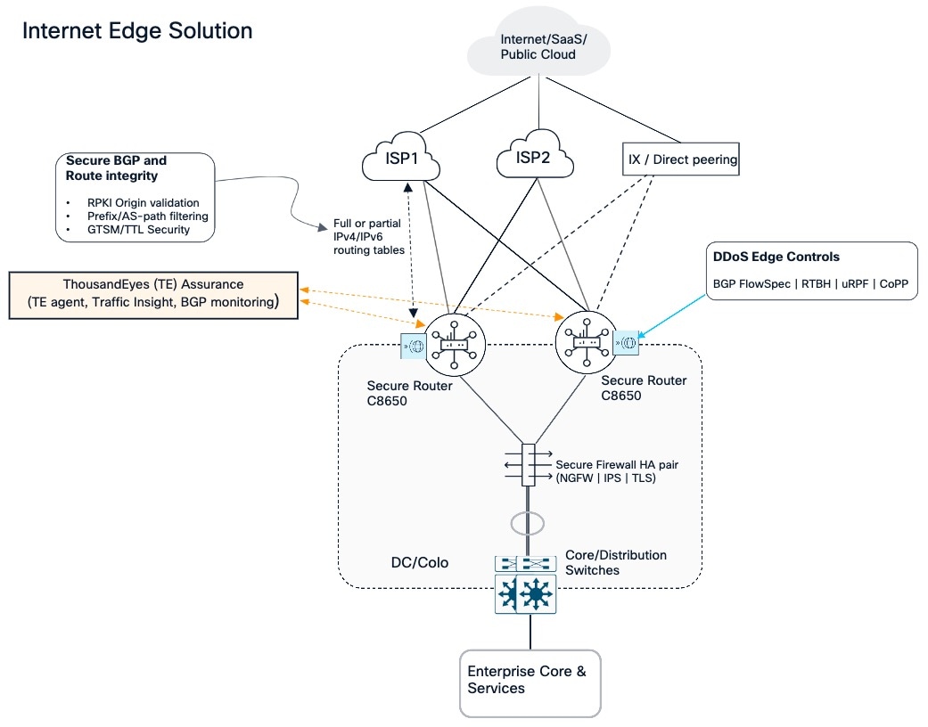
In traditional edge architectures, balancing massive internet routing tables, address translation, and deep packet inspection on a single platform often forced severe performance compromises. To resolve this, the Internet Edge Solution architecture explicitly decouples high-scale Layer 3 transit from application security. At the perimeter, two Cisco C8650 Secure Routers operate in an active/active configuration, using ECMP routing to equally distribute traffic across available paths and Bidirectional Forwarding Detection (BFD) to detect failures quickly. Traffic that requires deep inspection passes through a dedicated Cisco Secure Firewall HA pair, which provides next generation firewall services, intrusion prevention, and TLS inspection before forwarding it to the internal Cisco Core and distribution switches.
Because the gateway depends on reliable external routes, the routers also apply controls to protect routing and forwarding. RPKI origin validation, prefix and AS path filtering, and Generalized TTL Security Mechanism (GTSM) help secure BGP sessions and route information. During a denial-of-service event, BGP FlowSpec, remotely triggered blackholing, uRPF, and control plane policing provide additional controls at the edge. The routers also support WAN and LAN MACsec and PQC ready IPsec, while secure boot and Live Protect contribute to platform security
For assurance, ThousandEyes provides visibility into how well these Internet paths are performing. The Enterprise Agent can run tests from the gateway toward applications and destinations, while Traffic Insights correlates flow information with test results to show which traffic was present during a performance issue. BGP monitoring visibility helps operators understand route reachability and changes in the paths learned from providers.
This allows the operations team to compare provider paths, investigate whether a problem lies within the enterprise or farther along the Internet path, and verify the outcome after adjusting routing policy. Traffic Insights correlates flow data with ThousandEyes tests on Cisco Secure Routers.
Colocation and cloud gateway
Most enterprises now runs workloads in more than one public cloud , and the colocation facility is where those clouds meet the enterprise network. The Cloud gateway terminates private physical interconnects such as AWS Direct Connect, Microsoft Azure ExpressRoute, and Google Cloud Interconnect. It provides enterprise VRFs including those carrying AI workloads, predictable and high bandwidth access to each provider.
In enterprise architecture, multi-cloud interconnects are deployed across fragmented router pairs for each individual cloud provider. This fragmented approach created significant physical and operational sprawl, escalating colocation costs by consuming excessive rack space and power, while multiplying the management overhead required to maintain disparate hardware lifecycles and configuration baselines. The Cisco C8570 and C8650 Secure Router resolve these challenges by consolidating multi-cloud termination onto a high-performance, active-active redundant gateway.
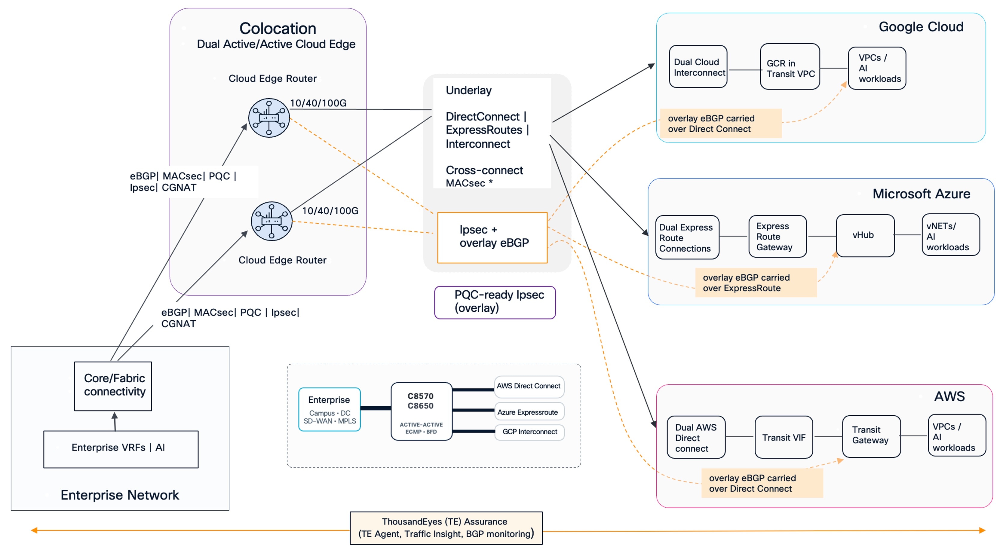
The Secure routers exchange routes with the cloud environments using eBGP and connect to AWS Direct Connect, Azure ExpressRoute, and Google Cloud Interconnect. The direct connections form the underlay, with MACsec protecting supported cross connects. Where encrypted overlay connectivity is required, IPsec carries the overlay, with eBGP exchanging routes across it.
Where supported by the circuit and provider handoff, MACsec protects the Ethernet cross connect between the colocation routers and the provider edge. Above that link, IPsec protects routed traffic between the configured tunnel endpoints. On supported Secure Router platforms and software releases, the IPsec tunnel can use post quantum cryptography ready key establishment. The cloud side must support the same method for the tunnel to negotiate PQC protection, so this needs to be validated separately for each cloud gateway.
Cloud connectivity options
The design supports two ways to connect from the colocation site into each cloud.
The first design uses the cloud provider’s native gateway for connectivity from the colocation site. In Google Cloud, Cloud Interconnect connects to a Google Cloud Router in a transit VPC, which provides reachability to workload VPCs. In Azure, ExpressRoute connects through the ExpressRoute Gateway and vHub to the VNets. In AWS, Direct Connect connects through a Transit VIF and Transit Gateway to the VPCs. The enterprise traffic path remains through the colocation Secure Routers and the private provider connection, with the cloud provider’s gateways and transit services handling connectivity on the cloud side.
The second design extends the enterprise network fabric directly into the public cloud environments. In this design, a redundant pair of Catalyst 8000v routers sits behind the provider’s gateway and in front of the cloud workload networks.
The physical circuit still terminates at the provider gateway, which remains part of the design. The C8kv pair adds an enterprise-controlled routing point between that gateway and the workloads. In Google Cloud, it sits in the Interconnect VPC behind the Cloud Router. In Azure, it sits behind the ExpressRoute Gateway and vHub. In AWS, it sits in the Transit VPC between the Direct Connect path and Transit Gateway.
This second design keeps the colocation as the enterprise’s traffic aggregation point while extending the enterprise routing and operations model into the cloud. The physical Secure Routers manage the high-capacity provider connections, route exchange, and encrypted paths at the colocation site and the C8kv pair provides a familiar enterprise routing point within the cloud, where routing policy, VRF and service VPN segmentation, IPsec, and telemetry can be aligned with the physical edge where supported. Where the enterprise uses Catalyst SD-WAN, the cloud hosted C8kv pair can serve as a gateway for the SD-WAN fabric.
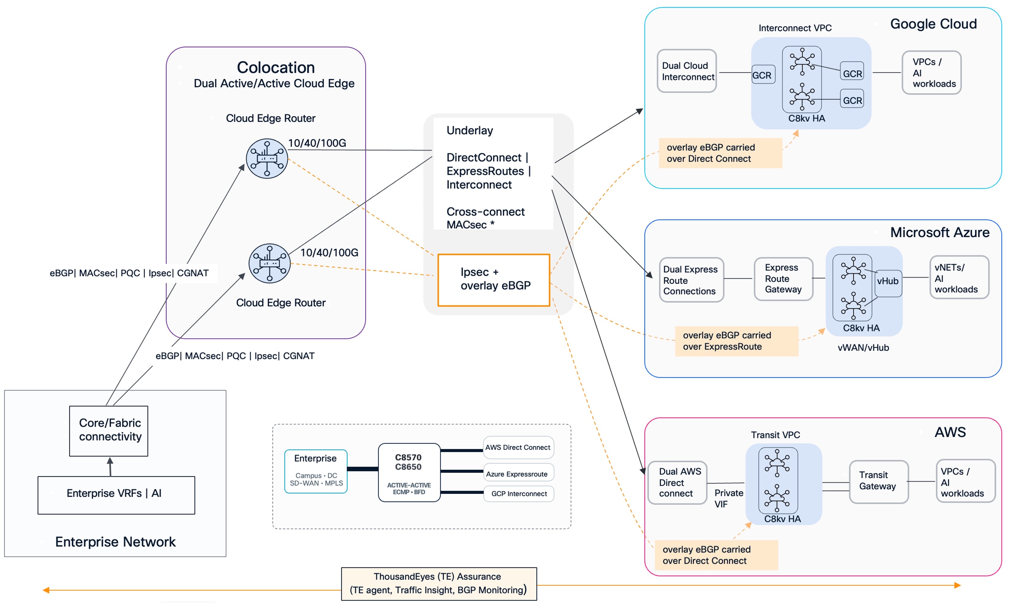
Both options let the enterprise connect its VRFs and workloads to cloud networks through redundant colocation routers and provider connections. The choice is whether to use the cloud provider’s native gateway path or to include the C8kv which adds a consistent enterprise routing tier inside the cloud without replacing the provider gateway or changing the role of the colocation site. This gives the design a choice between using provider native cloud gateways alone or adding C8kv when an enterprise controlled routing point closer to the workloads is valuable.
In both designs, ThousandEyes assurance spans the enterprise, colocation, and cloud paths. Its agent, Traffic Insights, and BGP monitoring provide path, traffic, and routing visibility to help operators investigate performance and verify routing behavior across the connections.
Campus WAN edge
The Campus WAN edge serves as the critical demarcation point connecting the localized SD-Access campus fabric with the external SD-WAN transport. It connects the users and devices in the campus fabric to the enterprise WAN, the public internet, and cloud delivered security services.
In this design, employees and contractors connect through the campus wired and wireless access layer. ISE and Duo provide identity and authentication context, which the network uses to place users into the right virtual network and apply the appropriate Security Group Tag. For example, employee and contractor traffic can remain separated even when both groups use the same campus infrastructure. Policies can also distinguish traffic within a group, so access is based on who or what is connecting and what it needs to reach.
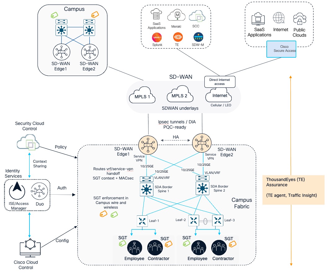
The campus fabric carries this segmentation through the access layer and toward the border spines. Layer 2 connectivity serves local endpoint access, while the fabric maintains the Layer 3 virtual network and routing context for each segment. At the fabric border, those virtual networks are handed to the SD-WAN edge as separate VRFs and mapped to corresponding SD-WAN service VPNs. The campus fabric therefore remains responsible for user access and local segmentation, while the WAN edge takes responsibility for routing between sites and selecting WAN transports.
At that border, dual Secure Routers C8400 connect the campus fabric to the WAN. Their links to the border spines provide path diversity, and the routers operate as a redundant pair, so a failure of one router or one connection does not have to take the campus offline. Secure Routers terminate underlays including MPLS circuits, DIA circuits, cellular, and low earth orbit satellite connections, presenting them to the network as a unified hybrid wide area network. To maintain application resiliency for interactive voice, video, and cloud workloads, the platform utilizes Enterprise Application-Aware Routing (eAAR) to continuously evaluate path quality. By measuring real time latency, jitter, and packet loss against strict application profiles, the system can detect service level agreement violations within five to ten seconds. Fast reroute in SD-WAN can provide sub-second convergence if local or remote WAN link failure occurs, ensuring seamless application continuity.
Because most campus traffic is destined for external cloud resources, local internet breakout eliminates the latency penalty of backhauling traffic to a centralized data center. North to south traffic leaving the campus for the internet passes directly through the firewall running on the Secure Router, with application control, intrusion prevention, URL filtering, and TLS inspection applied locally. The same on-box firewall can also inspect east to west traffic moving between segments inside the campus, though its scope must be defined precisely. Crucially, the Campus WAN Edge router is not intended to inspect all east to west campus traffic. The campus fabric maintains user and device segmentation close to the access layer and Cisco Secure Firewall handles the deeper inspection required for intersegment traffic. Hair pinning general campus east to west traffic into the WAN Edge router would overload routing resources on transit that should remain local.
End-to-end segmentation, PQC, and MACSec
The refresh brings three protections together across the campus and WAN: segmentation that follows users and devices, post quantum protection that begins with platform integrity and continues across the network, and MACsec coverage across supported wired links.
First, the platform establishes end-to-end segmentation. Segmentation starts when a user or device connects to the campus. ISE and Duo provide identity and authentication context, and the campus fabric uses that context to assign the endpoint to the right virtual network and Security Group Tag. Virtual networks provide separation between larger groups, such as employees and contractors, while SGT based policy controls communication between groups within the fabric. As traffic reaches the campus border, each virtual network maps to its corresponding SD-WAN service VPN. SGT context can continue across the SD-WAN overlay and, where configured, into Cisco Secure Access, allowing policy to follow the group across campus, WAN, and cloud security boundaries.
Second, the platform delivers end-to-end MACsec to secure the physical transport layer continuously across the entire enterprise footprint. Encryption is not limited to the WAN boundary, it starts inside the Campus. The MACsec design extends link protection on supported ethernet connections across the Campus and WAN. That includes the wired uplink from supported Cisco wireless access points, access and distribution switch connections, and the Secure Router’s supported LAN and WAN interfaces. Each Ethernet segment establishes MACsec protection with its directly connected peer, so the intended end to end outcome is coverage across the supported link chain from campus access through the WAN handoff.
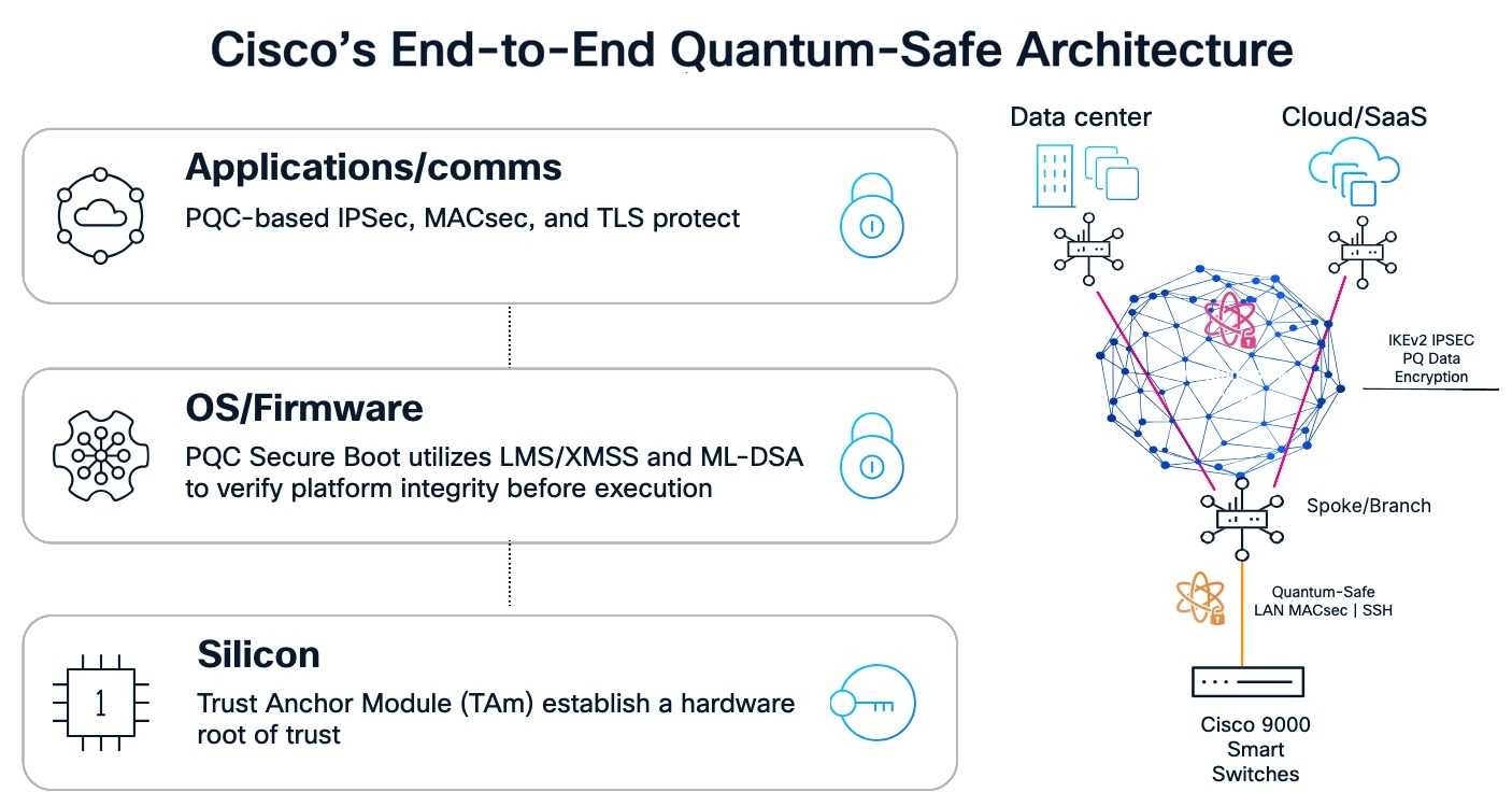
Finally, the refresh establishes an end-to-end quantum safe architecture designed to protect both enterprise data and platform infrastructure against emerging decryption threats. This defense is implemented across three distinct layers. At the foundational silicon layer, a dedicated Trust Anchor Module establishes a strict hardware root of trust. Above this, the operating system and firmware are protected by Post-Quantum Cryptography Secure Boot, which utilizes LMS, XMSS, and ML-DSA algorithms to cryptographically verify platform integrity before execution. Above that foundation, PQC ready IPsec protects the SD-WAN overlay between compatible Secure Router peers. The overlay can cross private MPLS circuits and public internet paths while keeping traffic encrypted between its tunnel endpoints. TLS protects application communications where it is used, while MACsec protects supported physical links. These layers carry cryptographic protection from the device itself into the network and application traffic, so PQC is part of the platform and not only a tunnel setting.
The result is one security foundation for the refreshed architecture. Segmentation preserves who is allowed to communicate as traffic crosses campus and WAN boundaries. PQC readiness strengthens confidence in the platform and in encrypted communications between supported endpoints, and MACsec protects the physical Ethernet links that carry the traffic. The campus fabric, the dedicated Secure Firewall, and Secure Routers each apply the protection suited to their role, creating a connected security design.
Figure 8 shows how operations span the campus fabric, WAN, identity, and security services. Cisco Cloud Control provides one dashboard for cloud-based configuration workflows, while Security Cloud Control provides unified security policy across the devices running security services. ThousandEyes adds assurance from the campus toward the WAN, internet, and SaaS destinations, helping teams determine whether a user experience issue originates in the local fabric, a selected transport, or an external service.
SD-WAN aggregation
The SD-WAN Aggregation Hub provides high-capacity overlay aggregation, complex routing exchange, and segmentation for distributed branch, campus, and colocation sites. The ASR 1000 Series remains widely deployed at the aggregation hub but since it was introduced, SD-WAN aggregation requirements have expanded to include pervasive encryption, larger routing tables, higher SD-WAN tunnel scale, and integrated deep packet inspection on same platform. Cisco 8000 Series Secure Routers are designed for these combined requirements, with newer cryptographic capabilities and higher aggregation bandwidth.
The refresh retains the hub’s role while giving it more capacity for overlay termination, encrypted traffic, and route aggregation. Cisco Secure Routers like high-end C8650 can support up to 12,000 SD-WAN tunnels with 80 Gbps of SD-WAN throughput.
As shown in the design, a redundant pair of Secure Routers sits at the data center or colocation hub. They terminate branch site tunnels, collect the service VPN routes, and connect those VPNs to the core through the routing and switching infrastructure. The hub remains a controlled transit point into the enterprise network, while the separate Internet Edge and Cloud Gateway roles continue to handle their own external connections.
Tunnel groups provide a way to organize the overlay as that hub grows. Branches can be assigned to groups that correspond to a preferred hub pair or service domain, and the hub router configuration controls which groupings it accepts. This limits unnecessary tunnel formation and makes it easier to scale the head end without requiring every site to build every possible tunnel. Router affinity complements this by influencing which hub is preferred when multiple eligible next hops exist. Hub routers can be assigned affinity groups, while branches or branch groups can be configured with a preference order. A set of branches can therefore prefer its regional or primary hub and use another hub when the preferred path is unavailable. Tunnel groups shape tunnel membership while affinity shapes next hop preference.
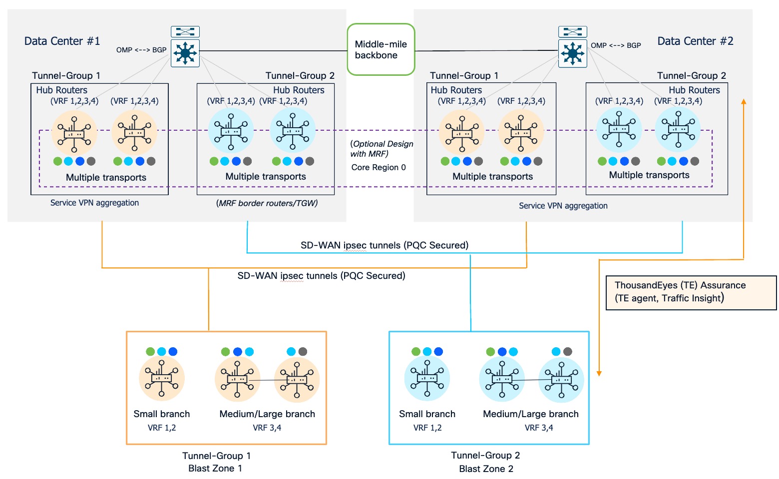
With this refresh, hub platforms such as C8500 and C8600 Secure Routers also provide per-packet load balancing which can extend the use of available WAN capacity beyond traditional per flow ECMP. It divides eligible single flows into smaller flowlets, distributes them over multiple paths, and reorders packets at the receiving router. This is useful for large transfers, backup traffic, and AI data movement that could otherwise be limited by a single path. It is a selective tool for high volume flows, since it has platform and policy requirements and is not intended for every traffic class. See Per Packet Load Balancing in SD-WAN.
There is also an alternative for networks designed around Multi Region Fabric. Instead of treating the aggregation routers only as standalone hubs, they can be assigned the border router role in the core region, Region 0. In that design, regional sites connect through their regional border routers, while the core region provides transit between regions and access to shared data center services. The hub routers then aggregate and exchange routes between the access regions and the core region. This approach fits an enterprise that wants a hierarchical regional fabric and centralized interregional routing. Cisco’s Multi Region Fabric guide describes the core region and the border router role.
For overlay confidentiality, the Secure Router refresh supports SD-WAN IKEv2 with post quantum key establishment on Cisco 8000 Series Secure Routers. MACsec is also available on all built-in ports of the C8500/C8600 Secure Router. This gives the refresh a more consistent option for protecting supported hub LAN and WAN handoffs, including high speed interfaces, than the model, port, and licensing dependent MACsec support in the ASR 1000 family.
ThousandEyes adds visibility from the hub across the SD-WAN overlay, underlay transport, and application paths. That helps operators distinguish a hub capacity or routing issue from a degraded carrier path or an issue beyond the enterprise network. Cisco supports ThousandEyes Enterprise Agent integration on Catalyst SD-WAN devices, with configuration and monitoring workflows through SD-WAN Manager. Cisco Cloud Control and connected management workflows can make configuration, policy, and assurance work more consistent across hubs and sites. Live Protect can add runtime mitigation for disclosed vulnerabilities on supported models and releases while the permanent software fix is scheduled and deployed.
MPLS VPN Aggregation
The Private MPLS Aggregation architecture provides dedicated transit for enterprises operating their own backbone networks. The design draws a strict and deliberate boundary between the customer edge and the provider edge.
The design connects campus, branch, and headquarters networks through an enterprise operated MPLS VPN. At each site, a pair of C8550 or C8570 Secure Routers acts as the customer edge (CE), connecting the local switching layer to the WAN. The routers terminate the site’s VRFs and apply its routing and quality of service policies, keeping employee, customer, and operational networks in separate routing domains as their traffic enters the enterprise VPN.
Each customer edge pair connects to both regional provider edge routers, providing paths through separate routers and links. Toward the LAN, the pair can present a redundant gateway using the selected first hop redundancy design. BFD can detect a failed CE to PE path, while the routing configuration determines how traffic uses the remaining path.
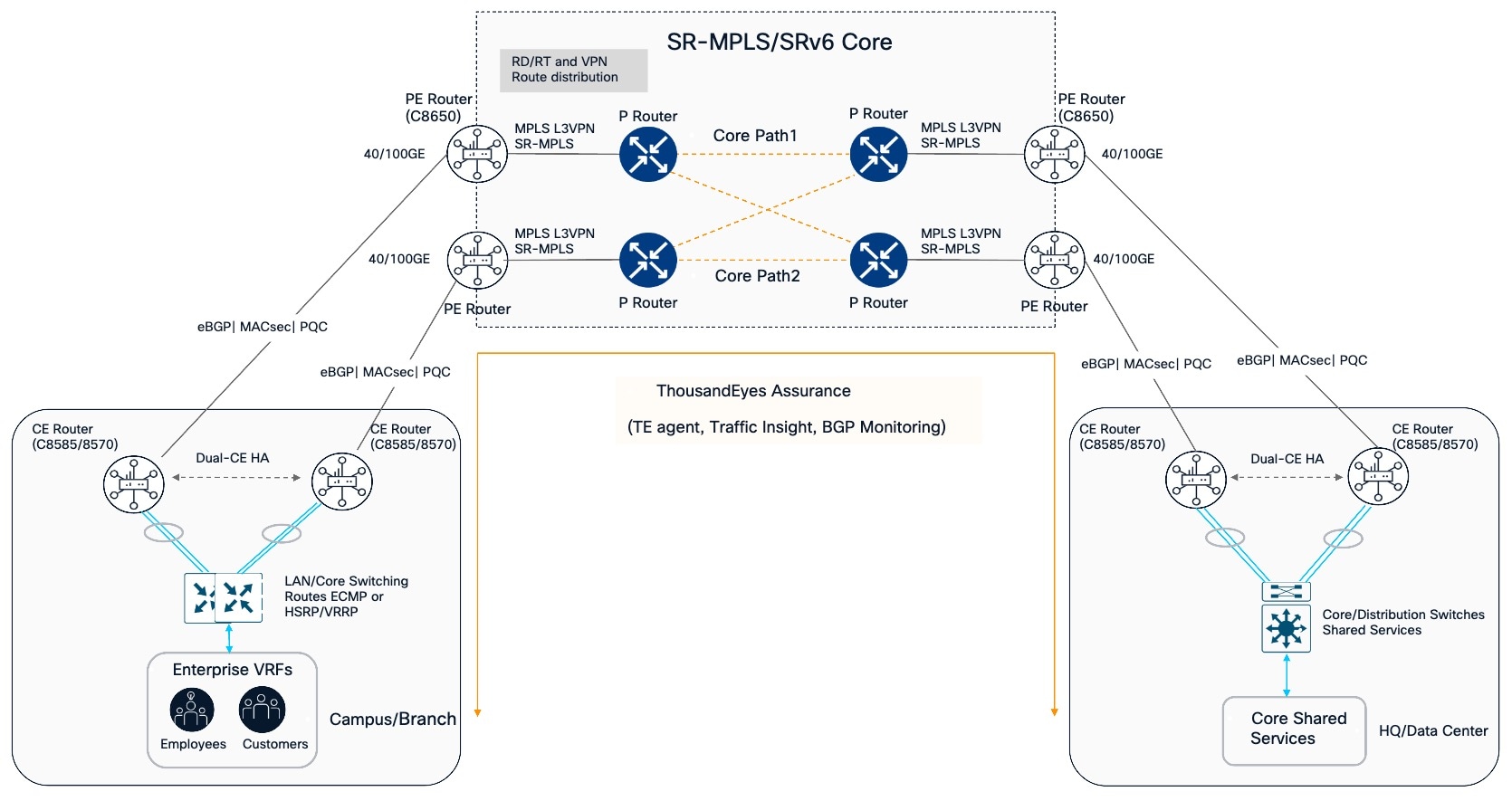
At regional aggregation, a pair of C8650 Secure Routers acts as the provider edge (PE). These routers terminate the site facing VPNs, maintain the VRF and route target policy that controls VPN membership, and exchange VPN routes using MP BGP. They apply quality of service where traffic from multiple sites converges, then forward traffic into the core. The provider edge can also provide a controlled point for shared services. Authentication, DNS, monitoring, and other common services can be made reachable through explicit inter VRF routing and the appropriate security policy, keeping access intentional without broadly importing routes between networks.
These provider edge nodes are deployed in fully active pairs. At this aggregation point, Hierarchical Quality of Service is applied to the aggregate traffic flowing into the core, managing contention where thousands of site flows converge. Shared infrastructure access, including authentication and name resolution, is managed at this tier as well. Instead of importing route targets across the fabric and hoping the resulting reachability matches the design intent, the provider edge utilizes deliberate inter-VRF constructs coupled with network address translation and firewall policies to provide secure access to shared services.
To modernize the underlying transit beneath these provider edge nodes, the architecture transitions the core from label distribution protocols to Segment Routing. This underlay uses Topology-Independent Loop-Free Alternate (TI-LFA) to provide sub-second failover for the provider edge traffic. Finally, to secure the physical transport between these aggregation sites, the hardware applies continuous line rate WAN MACsec, encrypting all core interconnects without reducing the performance of the encapsulated virtual private network traffic
The P routers carry traffic between the regional provider edges. The diagram shows two core paths, allowing the design to use multiple paths and core fast reroute where the selected topology and configuration support it. The MPLS VPN service and its route policy remain at the provider edge, while the P routers forward traffic through the core. The core can use Segment Routing over MPLS or SRv6. The Provider routers in the core are doing one thing at a very large scale, namely label switching at high speed with fast reconvergence and heavy interface density done by IOS-XR based routers.
The CE to PE route exchange uses eBGP, with route filters controlling which prefixes each side advertises and accepts. MACsec can encrypt a compatible Ethernet handoff between the CE and PE when both ends support it. For traffic that needs confidentiality across the routed core, IPsec can encrypt traffic between enterprise tunnel endpoints over the MPLS VPN, using post quantum key establishment supported by the selected routers. MACsec protects the handoff link, while IPsec protects traffic between its tunnel endpoints.
ThousandEyes adds visibility in the design through the Enterprise Agent, Traffic Insights on Secure routers, and BGP Monitoring. From there, operations teams can relate application experience to network paths and routing conditions across the sites and the core.
Architecture across network roles
Each role in this paper can be adopted on its own. The larger benefit comes from designing the Internet Edge, Cloud Gateway, Campus WAN Edge, SD-WAN Aggregation, and MPLS VPN Aggregation as connected parts of the same enterprise network. Each role has its own traffic profile, scale requirement, trust boundary, and failure domain. The architecture applies common principles for routing, segmentation, assurance, and operations while preserving the distinct responsibilities of each platform.
Cisco Secure Routers provide the routing and aggregation foundation at these enterprise network boundaries, while core provides high-scale transport and path control. At aggregation sites, where the design steers traffic between data center zones, VRFs, or shared services for inspection, dedicated Cisco Secure Firewall HA pairs provide stateful inspection and threat prevention. Keeping this inspection on a dedicated Cisco Secure firewall allows security capacity and policy to be sized and managed independently from Secure Router forwarding and maintains a distinct security boundary and failure domain.
When an enterprise standardizes on the same platform family, operating system, and policy model across the entire network, the individual benefits stop being separate and start compounding.
The scale of this compounding value is best illustrated through a highly distributed enterprise, such as a large financial institution. Consider a bank operating hundreds of small branches on an SD-WAN fabric, regional processing centers connected over a private MPLS Layer 3 virtual private network, centralized data centers managing public facing internet edges, and a colocation footprint facilitating multi-cloud risk analytics workloads. A transaction can cross several of these roles on its way from a branch user to a regional application and then to a cloud-based risk service.
Historically, securing these four diverse roles required four separate product lines, managed by four disparate tools, and operated by siloed engineering teams that typically only met during incident reviews. Consolidating these functions onto the Cisco Secure Router architecture fundamentally alters how the enterprise builds, scales, and secures its transit domains.
For organizations with ASR 1000 deployments, this architecture provided a role by role path to refresh those deployments with Cisco 8400, 8500 and 8600 Series Secure Routers. It shows how each refresh fits into the wider enterprise network, with consistent approaches to routing, segmentation, assurance, and operation across the roles.
Consistent segmentation across the enterprise
The most immediate operational advantage of a unified architecture is continuous identity propagation. When a branch teller requests access to a customer record, that traffic must cross multiple trust boundaries. The flow leaves the branch edge, transits the SD-WAN fabric to an Aggregation headend, crosses the enterprise core to a regional processing center, and finally traverses a colocation cross-connect to reach a cloud virtual private cloud.
In a network built from fragmented product lines, the user identity and segment rarely survive the first hop. Instead, security policies are reconstructed at every subsequent boundary using fragile IP address mappings. Each reconstruction introduces the risk of silent policy drift, often leaving administrators unable to definitively explain why a particular subnet retains specific access privileges years later.
By utilizing a continuous segmentation model everywhere, the group assigned at the campus access port is the exact group the aggregation headend acts upon, the provider edge maps to the virtual private network, and the colocation edge carries into the public cloud. The enterprise writes the policy once, and the network enforces it consistently at every transit point the traffic passes.
As another example, consider an employee at a branch who needs to access an approved application running in a public cloud. When the user authenticates to the local branch network, Cisco Identity Services Engine (ISE) validates their posture and assigns a localized Security Group Tag.
The Cisco Smart switch assigns the employee’s traffic an SGT based on identity and role. The branch Cisco Secure router carries that tag across the SD-WAN overlay to the Aggregation Secure Router, which forwards the traffic through the service VPN and a separate IPsec tunnel to the C8kv hosted in the public cloud.
The C8kv operating inside the cloud provider's Transit VPC decrypts the tunnel, extracts the SGT, and enforces the native Zero Trust policy directly at the cloud perimeter.
Unified PQC standardization
Standardizing on a single platform architecture also dictates how effectively an enterprise can harden itself against emerging threats. Post-quantum readiness is not a localized feature that only matters in one part of the network. Traffic that a regulator considers sensitive remains sensitive at the branch, across the wide area network, through the internet edge, and on the cloud circuit. Because malicious actors can capture data today and decrypt it later when quantum computing matures, the weakest transport link defines the exposure radius for the entire path.
Running one platform family across every routing role turns a complex cryptographic migration into a single, predictable program. The architecture applies the identical key establishment protocols, algorithm choices, and migration sequences from the branch level all the way to the multi-cloud colocation. Native MACsec protects the physical links wherever traffic traverses space the enterprise controls, including campus risers, customer edge to provider edge handoffs, internet edge circuits, and cloud cross-connects. Simultaneously, hardware accelerated IPsec with post-quantum ready key establishment protects the secure overlay wherever traffic crosses third party transport the enterprise does not own.
When regulators evaluate quantum readiness, the enterprise can answer for the entire network from one program, instead of reconciling different answers from four operations teams.
Operational simplicity across the enterprise network
Operating several network roles should not mean starting from scratch each time. Cisco Cloud Control gives teams a shared view of connected Cisco environments, including inventory, topology, alerts, and workflows. When an issue crosses network domains, teams can use that context to understand what is connected and where to investigate. Catalyst SD-WAN Manager and other product controllers continue to handle configuration for their respective domains.
Teams that want to automate configuration can also use Cisco Network as Code. For Catalyst SD-WAN, it uses YAML data and Terraform providers and modules to manage supported configurations through Catalyst SD-WAN Manager. Teams can apply configuration, read the current state, and address drift. See Network as Code for Catalyst SD-WAN.
For Secure Router running IOS XE, the Terraform provider communicates with devices through NETCONF and YANG. Teams describe the intended configuration in YAML and can reuse templates and device groups across routers. NETCONF must be enabled, and the management interface must be reachable from the automation environment. See Network as Code for IOS XE and IOS XE first steps.
Together, these tools can reduce repeated manual work and make configuration easier to review and reuse.
Standardizing the enterprise edge on Cisco 8000 Series Secure Routers means teams no longer have to trade forwarding capacity against security services at each boundary. Post-quantum ready encryption, fast failover, and ThousandEyes assurance are available in every role, and Cisco Cloud Control brings them into one operational view. The result is an edge that can carry growing cloud and AI traffic with the separation, scale, and predictable performance those workloads need.
References
Cisco Catalyst SD-WAN Multi-Region Fabric Configuration Guide, Releases 26.x and Later
Cisco Catalyst SD-WAN Solution Integrations Guide, Releases 26.x and Later
Building Quantum-Resilient Mission-Critical Networks with SRv6
Application-Aware Path Selection in SRv6 Networks
Configuring BGP monitors with TE

