Interface Overview

The Firewall Threat Defense device includes data interfaces that you can configure in different modes, as well as a management interface.

Management interface

A management interface is a shared physical interface that enables communication between the diagnostic logical interface and the management logical interface on security appliances.

Interface configuration details

In Version 7.3 and earlier, the physical management interface is shared between the Diagnostic logical interface and the Management logical interface. In Version 7.4 and later, the diagnostic interface is merged with management for a simplified user experience.

Management interface

The Management interface is separate from the other interfaces on the device. It is used to set up and register the device to the Firewall Management Center. It uses its own IP address and static routing.

Management interface configuration and monitoring

You can configure its settings at the CLI using the configure network command. You can also view its status on the Devices > Device Management page. If you change the IP address at the CLI after you add it to the Firewall Management Center, you can match the IP address in the Secure Firewall Management Center in the Devices > Device Management area.

You can alternatively manage the Firewall Threat Defense using a data interface instead of the management interface.

Diagnostic interface

Diagnostic interface shares a physical port with the Management interface but requires different IP addresses on the same network. A diagnostic interface allows only management traffic.

Legacy diagnostic interface support

For new devices using 7.4 and later, you cannot use the legacy Diagnostic interface. Only the merged Management interface is available.

If you upgraded to 7.4 or later, and you did not have any configuration for the Diagnostic interface, then the interfaces will merge automatically.

If you upgraded to 7.4 or later, and you have configuration for the Diagnostic interface, then you have the choice to merge the interfaces manually, or you can continue to use the separate Diagnostic interface. Support for the Diagnostic interface will be removed in a later release, so you should plan to merge the interfaces as soon as possible. To manually merge the Management and Diagnostic interfaces, see Merge the management and diagnostic interfaces. Configurations that prevent an automatic merge include these:

  • A data interface named "management"—This name is reserved for use with the merged Management interface.

  • IP Address on Diagnostic

  • DNS enabled on Diagnostic

  • Syslog, SNMP, RADIUS or AD (for remote access VPN) source interface is Diagnostic

  • RADIUS or AD (for remote access VPN) with no source interface specified, and there is at least one interface configured as management-only (including Diagnostic)—The default route lookup for these services has changed from the management-only routing table to the data routing table, with no fallback to management. Therefore, you cannot use a management-only interface other than Management.

  • Static routes on Diagnostic

  • Dynamic routing on Diagnostic

  • HTTP server on Diagnostic

  • ICMP on Diagnostic

  • DDNS for Diagnostic

  • FlexConfig using Diagnostic

For more information about how the legacy Diagnostic interface operates, see the 7.3 version of this guide.

Interface Mode and Types

You can deploy Firewall Threat Defense interfaces in two modes: Regular firewall mode and IPS-only mode. You can include both firewall and IPS-only interfaces on the same device.

Regular Firewall Mode

Firewall mode interfaces subject traffic to firewall functions such as maintaining flows, tracking flow states at both IP and TCP layers, IP defragmentation, and TCP normalization. You can also optionally configure IPS functions for this traffic according to your security policy.

The types of firewall interfaces you can configure depends on the firewall mode set for the device: routed or transparent mode. See Transparent or Routed Firewall Mode for more information.

  • Routed mode interfaces (routed firewall mode only)—Each interface that you want to route between is on a different subnet.

  • Bridge group interfaces (routed and transparent firewall mode)—You can group together multiple interfaces on a network, and the Firewall Threat Defense device uses bridging techniques to pass traffic between the interfaces. Each bridge group includes a Bridge Virtual Interface (BVI) to which you assign an IP address on the network. In routed mode, the Firewall Threat Defense device routes between BVIs and regular routed interfaces. In transparent mode, each bridge group is separate and cannot communicate with each other.

IPS-Only Mode

You can configure your device in either a passive or inline IPS deployment. In a passive deployment, you deploy the system out-of-band from the flow of network traffic. In an inline deployment, you configure the system transparently on a network segment by binding two interfaces together.

Security zones and interface groups

You can assign each interface to a security zone, an interface group, or both. You then apply your security policy based on zones or groups. For example, you can assign the "inside" interface on one or more devices to the "inside" zone, and the "outside" interfaces to the "outside" zone. You can then configure your access control policy to enable traffic to go from the inside zone to the outside zone for every device using the same zones.

Security zones and interface groups functionality

To view the interfaces that belong to each object, choose Objects > Object Management and click Interface. This page lists the security zones and interface groups configured on your managed devices. You can expand each interface object to view the type of interfaces in each interface object.


Note


Policies that apply to any zone (a global policy) apply to interfaces in zones as well as any interfaces that are not assigned to a zone.


Note


The Management interface does not belong to a zone or interface group.


Security zones and interface groups have different membership and usage characteristics:

  • Security zones—An interface can belong to only one security zone.

  • Interface groups—An interface can belong to multiple interface groups (and to one security zone).

    You can use interface groups in NAT policies, prefilter policies, and QoS policies, as well as features that let you specify the interface name directly, such as Syslog servers or DNS servers.

Some policies only support security zones, while other policies support zones and groups. Unless you need the functionality an interface group provides, you should default to using security zones because security zones are supported for all features.

You cannot change an existing security zone to an interface group or vice-versa. Instead, you must create a new interface object.


Note


Although tunnel zones are not interface objects, you can use them in place of security zones in certain configurations; see Using tunnel zones to apply access control at the tunnel level.


Interface objects are categorized by these types:

  • Passive—For IPS-only passive or ERSPAN interfaces.

  • Inline—For IPS-only inline set interfaces.

  • Switched—For regular firewall bridge group interfaces.

  • Routed—For regular firewall routed interfaces.

  • ASA—(Security zones only) For legacy ASA FirePOWER device interfaces.

  • Management—(Interface groups only) For management-only interfaces.

  • Loopback—(Interface groups only) For loopback interfaces.

All interfaces in an interface object must be of the same type. After you create an interface object, you cannot change the type of interfaces it contains.

The interface (or zone name) itself does not provide any default behavior in regarding the security policy. We recommend using names that are self-describing to avoid mistakes in future configuration. A good name signifies a logical segment or traffic specification, for example:

  • Names of internal interfaces—InsideV110, InsideV160, InsideV195

  • Names of DMZ interfaces—DMZV11, DMZV12, DMZV-TEST

  • Names of external interfaces—Outside-ASN78, Outside-ASN91

Auto-MDI/MDIX feature

Auto-MDI/MDIX is a feature that eliminates the need for crossover cabling by performing an internal crossover when a straight cable is detected during the auto-negotiation phase. The feature is enabled by default with auto-negotiation on RJ-45 interfaces and requires either speed or duplex to be set to auto-negotiate. If you explicitly set both the speed and duplex to a fixed value, thus disabling auto-negotiation for both settings, then Auto-MDI/MDIX is also disabled. For Gigabit Ethernet, when the speed and duplex are set to 1000 and full, then the interface always auto-negotiates; therefore Auto-MDI/MDIX is always enabled and you cannot disable it.

Redundant interfaces (deprecated)

Redundant interfaces were supported for the ASA 5500-X platforms only. We don't recommend configuring them for other platforms.

Default settings for interfaces

This section lists default settings for interfaces.

Default state of interfaces

The default state of an interface depends on the type.

  • Physical interfaces—Disabled. The exception is the Management interface that is enabled for initial setup. Physical interfaces includes switch ports.

  • VLAN subinterfaces—Enabled. However, for traffic to pass through the subinterface, the physical interface must also be enabled.

  • EtherChannel port-channel interfaces (ISA 3000)—Enabled. However, for traffic to pass through the EtherChannel, the channel group physical interfaces must also be enabled.

  • EtherChannel port-channel interfaces (Firepower and Secure Firewall models)—Disabled.


Note


For the Firepower 4100/9300, you can administratively enable and disable interfaces in both the chassis and in the Firewall Management Center. For an interface to be operational, the interface must be enabled in both operating systems. Because the interface state is controlled independently, you may have a mismatch between the chassis and Firewall Management Center.


Default speed and duplex

By default, the speed and duplex for copper (RJ-45) interfaces are set to auto-negotiate.

By default, the speed and duplex for fiber (SFP) interfaces are set to the maximum speed, with auto-negotiation enabled. If a peer switch connecting to the port over a 50G cable does not support auto-negotiation, ensure to disable auto-negotiation on the switch and the Threat Defense interface as well. For example, N9K-C93400LD-H1 does not support auto-negotiation on a 50G cable. Hence, you must disable the default auto-negotiation on the platform and the switch for the port to be connected.

For the Secure Firewall 3100/4200 the speed is set to detect the installed SFP speed.

Create security zone and interface group objects

Create empty interface objects that can be populated with interfaces later, or create security zones while configuring interfaces to provide logical grouping and management of device interfaces.

Add security zones and interface groups to which you can assign device interfaces.


Tip


You can create empty interface objects and add interfaces to them later. To add an interface, the interface must have a name. You can also create security zones (but not interface groups) while configuring interfaces.


Before you begin

Understand the usage requirements and restrictions for each type of interface object. See Security zones and interface groups.

Procedure


Step 1

Choose Objects > Object Management > Interface.

Step 2

Click Add > Security Zone or Add > Interface Group.

Step 3

Enter a Name.

Do not use the same name as a network or port object. These object names are deployed to the device, and duplicate names result in a failed deployment.

Step 4

Choose an Interface Type.

Step 5

(Optional) From the Device > Interfaces drop-down list, choose a device that contains interfaces you want to add.

You do not need to assign interfaces on this screen; you can instead assign interfaces to the zone or group when you configure the interface.

Step 6

Click Save.


What to do next

Enable the physical interface and configure Ethernet settings

Before you begin

If you changed the physical interfaces on the device after you added it to the Firewall Management Center , you need to refresh the interface listing by clicking Sync Interfaces from device on the top left of Interfaces . For the 3100 /4200 , which supports hot swapping, see Network module management for Secure Firewall 3100/4200 before you change interfaces on a device.

This section describes how to:

  • Enable the physical interface. By default, physical interfaces are disabled (with the exception of the Management interface).

  • Set a specific speed and duplex. By default, speed and duplex are set to Auto.

This procedure only covers a small subset of interface settings. Refrain from setting other parameters at this point. For example, you cannot name an interface that you want to use as part of an EtherChannel interface. The exact interface options vary depending on your model and interface type.


Note


For the Firepower 4100/9300 , you configure basic interface settings in FXOS. See Configure a Physical Interface for more information.


Note


For switch ports, see Configure switch ports .


You can also click the Virtual Tunnels tab to view details of dynamic and static VTIs of route-based VPNs on the device. For more information, see View virtual tunnel interface details .

Procedure


Step 1

Select Devices > Device Management and click Edit (edit icon) for your Firewall Threat Defense device. The Interfaces page is selected by default.

Step 2

Click Edit (edit icon) for the interface you want to edit.

Step 3

Enable the interface by checking the Enabled check box.

  1. (Optional) Add a description in the Description field.

    The description can be up to 200 characters on a single line, without carriage returns.

Step 4

(Optional) Set the duplex and speed by clicking Hardware Configuration > Speed .

  • Duplex —Choose Full or Half . SFP interfaces only support Full duplex.

  • Speed —Choose a speed (varies depending on the model). For SFPs, choose Detect SFP to detect the speed of the installed SFP module and use the appropriate speed. Duplex is always full, autonegotiation is enabled, and FEC is set to auto. For dual-speed transceivers, the lower speed is used. This option is useful if you later change the network module to a different model, and want the speed to update automatically. Some switches and transceivers don't support autonegotiation, especially for higher speed interfaces. In this case, set the interface on the Firewall Threat Defense to a manual speed and also disable Auto-negotiation so the link can come up.

    Note

     
    You cannot modify the speed of a high availability or a cluster control link interface.
  • Auto-negotiation —Set the interface to negotiate the link status and flow control.

    Except for the 1100 , autonegotiation is set separately from the speed. Some switches don't support autonegotiation, especially for higher speed interfaces. In this case, set the interface on the Firewall Threat Defense to a manual speed and also disable Auto-negotiation so the link can come up.

  • Forward Error Correction Mode —For 25Gbps and higher interfaces, enable Forward Error Correction (FEC).

    For an EtherChannel member interface, configure FEC before adding it to the EtherChannel. If you remove the interface from EtherChannel and then reboot, reconfigure the FEC for the interface.

    Some switches don't support auto mode for FEC, especially for larger interfaces. Be sure to manually configure the setting, depending on the switch support. We don't recommend disabling FEC because the EtherChannel may not function correctly.

    The setting chosen when you use auto depends on the transceiver type and whether the interface is fixed (built-in) or on a network module.

    Table 1. Default FEC for Auto Setting

    Transceiver Type

    Fixed Port Default FEC (Ethernet 1/9 through 1/16)

    Network Module Default FEC

    25G-SR

    Clause 108 RS-FEC

    Clause 108 RS-FEC

    25G-LR

    Clause 108 RS-FEC

    Clause 108 RS-FEC

    10/25G-CSR

    Clause 108 RS-FEC

    Clause 74 FC-FEC

    25G-AOC x M

    Clause 74 FC-FEC

    Clause 74 FC-FEC

    25G-CU2.5/3M

    Auto-Negotiate

    Auto-Negotiate

    25G-CU4/5M

    Auto-Negotiate

    Auto-Negotiate

    25/50/100G

    Clause 91 RS-FEC

    Clause 91 RS-FEC

Note


From Version 7.4.2, Firewall Threat Defense supports the SFP 10G_25G_CSR_S module. To avoid link-down issues after a reboot, Forward Error Correction (FEC) must be enabled on these interfaces.

Step 5

(Optional) Enable Link Layer Discovery Protocol (LLDP) by clicking Hardware Configuration > Network Connectivity .

  • Enable LLDP Receive —Enables the firewall to receive LLDP packets from its peers.

  • Enable LLDP Transmit —Enables the firewall to send LLDP packets to its peers.

Step 6

(Optional) Enable pause (XOFF) frames for flow control by clicking Hardware Configuration > Network Connectivity , and checking Flow Control Send .

Flow control enables connected Ethernet ports to control traffic rates during congestion by allowing congested nodes to pause link operation at the other end. If the threat defense port experiences congestion (exhaustion of queuing resources on the internal switch) and cannot receive any more traffic, it notifies the other port by sending a pause frame to stop sending until the condition clears. Upon receipt of a pause frame, the sending device stops sending any data packets, which prevents any loss of data packets during the congestion period.

Note


The Firewall Threat Defense supports transmitting pause frames so that the remote peer can rate-control the traffic.

However, receiving of pause frames is not supported.

The internal switch has a global pool of 8000 buffers of 250 bytes each, and the switch allocates buffers dynamically to each port. A pause frame is sent out every interface with flowcontrol enabled when the buffer usage exceeds the global high-water mark (2 MB (8000 buffers)); and a pause frame is sent out of a particular interface when its buffer exceeds the port high-water mark (.3125 MB (1250 buffers)). After a pause is sent, an XON frame can be sent when the buffer usage is reduced below the low-water mark (1.25 MB globally (5000 buffers); .25 MB per port (1000 buffers)). The link partner can resume traffic after receiving an XON frame.

Only flow control frames defined in 802.3x are supported. Priority-based flow control is not supported.

Step 7

In the Mode drop-down list, choose one of the following:

  • None —Choose this setting for regular firewall interfaces and inline sets. The mode will automatically be changed to Routed, Switched, or Inline based on further configuration.

  • Passive —Choose this setting for passive IPS-only interfaces.

  • Erspan —Choose this setting for ERSPAN passive IPS-only interfaces.

Step 8

In the Priority field, enter a number ranging from 0–65535.

This value is used in the policy based routing configuration. The priority is used to determine how you want to distribute the traffic across multiple egress interfaces.

Step 9

Click OK .

Click Save.

Go to Deploy > Deploy and deploy the policy to assigned devices. The changes are not active until you deploy them.


What to do next

Continue configuring interfaces.

Configure EtherChannel interfaces

This section tells how to configure EtherChannel interfaces.


Note


For the Firepower 4100/9300, you configure EtherChannels in FXOS. Refer to Add an EtherChannel (Port Channel) for more information.


About EtherChannels

This section describes EtherChannels.

EtherChannels

An 802.3ad EtherChannel is a logical interface, called a port-channel interface) that consists of a bundle of individual Ethernet links, known as a channel group. This approach increases the bandwidth for a single network. A port channel interface is used in the same way as a physical interface when you configure interface-related features.

You can configure up to 48 EtherChannels, depending on how many interfaces your model supports.

Channel group interfaces

Channel group interfaces enable EtherChannel aggregation with specific capacity and configuration requirements. Understanding these interface specifications ensures proper EtherChannel deployment and performance.

Each channel group can have up to 8 active interfaces, except for the ISA 3000, which support 16 active interfaces. On switches that support only 8 active interfaces, you can assign up to 16 interfaces to a channel group. Only 8 interfaces can be active, the remaining interfaces can act as standby links in case of interface failure.

All interfaces in the channel group must be the same type and speed. The first interface added to the channel group determines the correct type and speed.

The EtherChannel aggregates traffic across all the available active interfaces in the channel. A proprietary hash algorithm selects the interface, using criteria such as source or destination MAC addresses, IP addresses, TCP and UDP port numbers, and VLAN numbers.

EtherChannel connection to other devices

An EtherChannel connection to other devices requires the connected device to support 802.3ad EtherChannels for compatibility.

EtherChannel connection requirements and configurations

The device to which you connect the Firewall Threat Defense EtherChannel must also support 802.3ad EtherChannels. For example, you can connect to the Catalyst 6500 switch or the Cisco Nexus 7000.

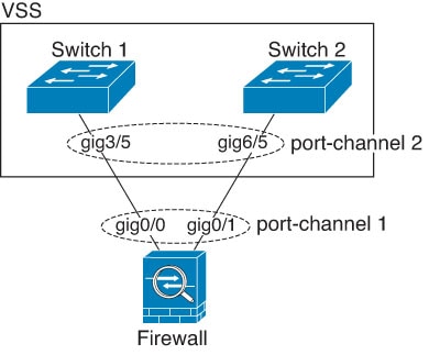
When the switch is part of a Virtual Switching System (VSS) or Virtual Port Channel (vPC), you can connect Firewall Threat Defense interfaces within the same EtherChannel to separate switches in the VSS/vPC. The switch interfaces are members of the same EtherChannel port-channel interface because the separate switches act like a single switch.

Figure 1. Connecting to a VSS/vPC
The diagram illustrates the connection of switch interfaces within an EtherChannel to separate switches in a Virtual Switching System (VSS) or Virtual Port Channel (vPC), highlighting how these interfaces function as a unified port-channel interface.

Note


If the Firewall Threat Defense device is in transparent firewall mode, and you place the Firewall Threat Defense device between two sets of VSS/vPC switches, then be sure to disable Unidirectional Link Detection (UDLD) on any switch ports connected to the Firewall Threat Defense device with an EtherChannel. If you enable UDLD, then a switch port may receive UDLD packets sourced from both switches in the other VSS/vPC pair. The receiving switch will place the receiving interface in a down state with the reason "UDLD Neighbor mismatch".


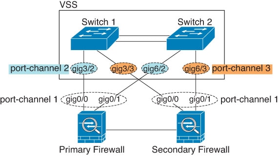
If you use the Firewall Threat Defense device in an Active/Standby failover deployment, you need to create separate EtherChannels on the switches in the VSS/vPC, one for each Firewall Threat Defense device. On each Firewall Threat Defense device, a single EtherChannel connects to both switches. Even if you could group all switch interfaces into a single EtherChannel connecting to both Firewall Threat Defense devices,the EtherChannel would not be established because of the separate Firewall Threat Defense system IDs. Also, using a single EtherChannel would not be desirable because you do not want traffic sent to the standby Firewall Threat Defense device.

Figure 2. Active/Standby failover and VSS/vPC
The diagram illustrates the Active/Standby failover configuration alongside Virtual Switching System (VSS) and Virtual Port Channel (vPC) setups, highlighting the connections between devices in a network.
Link aggregation control protocol

The Link Aggregation Control Protocol (LACP) is a network protocol that aggregates interfaces by exchanging the Link Aggregation Control Protocol Data Units (LACPDUs) between two network devices.

LACP interface configuration modes

You can configure each physical interface in an EtherChannel to be:

  • Active—Sends and receives LACP updates. An active EtherChannel can establish connectivity with either an active or a passive EtherChannel. You should use the active mode unless you need to minimize the amount of LACP traffic.

  • Passive—Receives LACP updates. A passive EtherChannel can only establish connectivity with an active EtherChannel. Not supported on hardware models.

  • On—The EtherChannel is always on, and LACP is not used. An "on" EtherChannel can only establish a connection with another "on" EtherChannel.

LACP coordinates the automatic addition and deletion of links to the EtherChannel without user intervention. It also handles misconfigurations and checks that both ends of member interfaces are connected to the correct channel group. "On" mode cannot use standby interfaces in the channel group when an interface goes down, and the connectivity and configurations are not checked.

Load balancing

Load balancing is a distribution mechanism that distributes packets to interfaces in the EtherChannel and ensures transparent failover when active interfaces go down by rebalancing traffic between remaining links.

Load balancing operation details

The Firewall Threat Defense device distributes packets to the interfaces in the EtherChannel by hashing the source and destination IP address of the packet (this criteria is configurable). The resulting hash is divided by the number of active links in a modulo operation where the resulting remainder determines which interface owns the flow. All packets with a hash_value mod active_links result of 0 go to the first interface in the EtherChannel, packets with a result of 1 go to the second interface, packets with a result of 2 go to the third interface, and so on. For example, if you have 15 active links, then the modulo operation provides values from 0 to 14. For 6 active links, the values are 0 to 5, and so on.

If an active interface goes down and is not replaced by a standby interface, then traffic is rebalanced between the remaining links. The failure is masked from both Spanning Tree at Layer 2 and the routing table at Layer 3, so the switchover is transparent to other network devices.

EtherChannel MAC address

An EtherChannel MAC address is a network identifier that is shared by all interfaces in the EtherChannel group. This makes the EtherChannel transparent to network applications and users by presenting one logical connection.

All interfaces that are part of the channel group share the same MAC address. This feature makes the EtherChannel transparent to network applications and users, because they only see the one logical connection; they have no knowledge of the individual links.

Platform-specific MAC address behavior

MAC address assignment for EtherChannel interface varies by hardware platform.

Firepower and Secure Firewall Hardware

The port-channel interface uses the MAC address of the internal interface Internal-Data 0/1. You can manually configure a MAC address for the port-channel interface if needed. All EtherChannel interfaces on a chassis use the same MAC address, so be aware that if you use SNMP polling, for example, multiple interfaces will have the same MAC address.


Note


Member interfaces only use the Internal-Data 0/1 MAC address after a reboot. Prior to rebooting, the member interface uses its own MAC address. If you add a new member interface after a reboot, you will have to perform another reboot to update its MAC address.


Guidelines for EtherChannels and redundant interfaces

Provides essential configuration rules and limitations for implementing EtherChannels and redundant interfaces to maintain network stability and high availability.

Bridge Group

In routed mode, Firewall Management Center -defined EtherChannels are not supported as bridge group members. EtherChannels on the Firepower 4100/9300 can be bridge group members.

High availability

  • When you use an EtherChannel interface as a High availability link, it must be pre-configured on both units in the High availability pair; you cannot configure it on the primary unit and expect it to replicate to the secondary unit because the High availability link itself is required for replication .

  • If you use an EtherChannel interface for the state link, no special configuration is required; the configuration can replicate from the primary unit as normal. For the Firepower 4100/9300 chassis , all interfaces, including EtherChannels, need to be pre-configured on both units.

  • You can monitor EtherChannel interfaces for High availability . When an active member interface fails over to a standby interface, this activity does not cause the EtherChannel interface to appear to be failed when being monitored for device-level High availability . Only when all physical interfaces fail does the EtherChannel interface appear to be failed (for an EtherChannel interface, the number of member interfaces allowed to fail is configurable) .

  • If you use an EtherChannel interface for a High availability or state link, then to prevent out-of-order packets, only one interface in the EtherChannel is used. If that interface fails, then the next interface in the EtherChannel is used. You cannot alter the EtherChannel configuration while it is in use as a High availability link. To alter the configuration, you need to temporarily disable High availability , which prevents High availability from occurring for the duration.

Model Support

  • You cannot add EtherChannels in the Firewall Management Center for the Firepower 4100/9300 or the Firewall Threat Defense Virtual . The Firepower 4100/9300 supports EtherChannels, but you must perform all hardware configuration of EtherChannels in FXOS on the chassis.

  • You cannot use Firepower 1010 or Secure Firewall 1210/1220 switch ports or VLAN interfaces in EtherChannels.

Clustering

  • To configure a spanned EtherChannel or an individual cluster interface, see the clustering chapter.

General Redundant Interface Guidelines

  • You can configure up to 8 redundant interface pairs.

  • All the Firewall Threat Defense configuration refers to the logical redundant interface instead of the member physical interfaces.

  • You cannot use a redundant interface as part of an EtherChannel, nor can you use an EtherChannel as part of a redundant interface. You cannot use the same physical interfaces in a redundant interface and an EtherChannel interface. You can, however, configure both types on the Firewall Threat Defense device if they do not use the same physical interfaces.

  • If you shut down the active interface, then the standby interface becomes active.

  • Redundant interfaces do not support the Management slot / port interfaces as members. You can, however, set a redundant interface comprised of non- Management interfaces as management-only.

General EtherChannel Guidelines

  • You can configure up to 48 EtherChannels, depending on how many interfaces are available on your model.

  • Each channel group can have up to 8 active interfaces, except for ASA models and the ISA 3000, which supports 16 active interfaces. For switches that support only 8 active interfaces, you can assign up to 16 interfaces to a channel group: while only 8 interfaces can be active, the remaining interfaces can act as standby links in case of interface failure.

  • When you add the first member interface, it sets the required hardware properties of all member interfaces.

    • The media type of member interfaces can be either RJ-45 or SFP; SFPs of different types (copper and fiber) can be mixed. You cannot mix RJ-45 and SFP interfaces.

    • All interfaces must be set to the same speed and duplex.

    • The first interface sets the speed capacity , which cannot be changed later.

  • The device to which you connect the Firewall Threat Defense EtherChannel must also support 802.3ad EtherChannels.

  • The Firewall Threat Defense device does not support LACPDUs that are VLAN-tagged. If you enable native VLAN tagging on the neighboring switch using the Cisco IOS vlan dot1Q tag native command, then the Firewall Threat Defense device will drop the tagged LACPDUs.

  • The LACP rate depends on the model. When you set the rate (normal or fast), the device requests that rate from the connecting switch.

  • In Cisco IOS software versions earlier than 15.1(1)S2, Firewall Threat Defense does not support connecting an EtherChannel to a switch stack. To improve compatibility, set the stack-mac persistent timer command to a large enough value to account for reload time.

  • All the Firewall Threat Defense configuration refers to the logical EtherChannel interface instead of the member physical interfaces.

Configure an EtherChannel

Create an EtherChannel port-channel interface to aggregate multiple physical interfaces into a single logical interface for increased bandwidth and redundancy.

This section describes how to create an EtherChannel port-channel interface, assign interfaces to the EtherChannel, and customize the EtherChannel.


Note


For the Firepower 4100/9300, you configure EtherChannels in FXOS. See Add an EtherChannel (Port Channel) for more information.


Before you begin

  • When you add the first member interface, it sets the required hardware properties of all member interfaces. See Guidelines for EtherChannels and redundant interfaces for more details about member interface requirements.

  • You cannot add a physical interface to the channel group if you configured a name for it. You must first remove the name.


    Note


    If you are using a physical interface already in your configuration, removing the name will clear any configuration that refers to the interface.


Follow these steps to configure an EtherChannel:

Procedure


Step 1

Select Devices > Device Management and click Edit (edit icon) for your Firewall Threat Defense device. The Interfaces page is selected by default.

Step 2

Enable the member interfaces according to Enable the physical interface and configure Ethernet settings.

Step 3

Click Add Interfaces > Ether Channel Interface.

Step 4

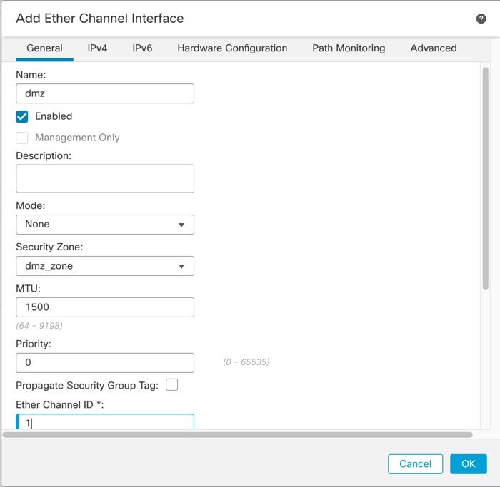
On the General tab, set the Ether Channel ID to a number between 1 and 48 (1 and 8 for the Firepower 1010 and Secure Firewall 1210, 1 and 10 for the Secure Firewall 1220).

Figure 3. Add EtherChannel interface
Add EtherChannel Interface

Step 5

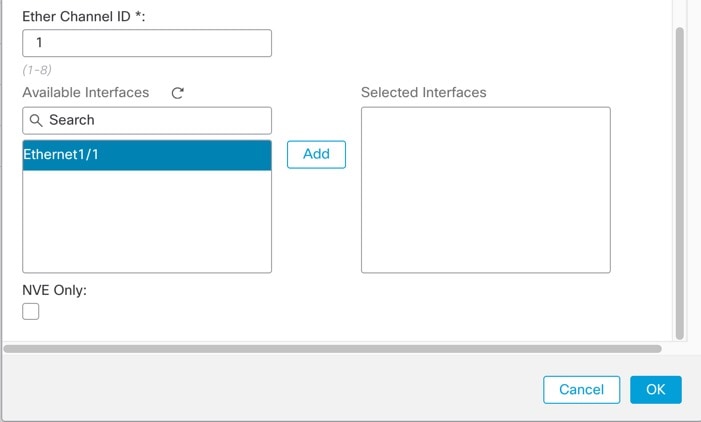
In the Available Interfaces area, click an interface and then click Add to move it to the Selected Interfaces area. Repeat for all interfaces that you want to make members.

Make sure all interfaces are the same type and speed capability.

Figure 4. Available interfaces
Available Interfaces

Step 6

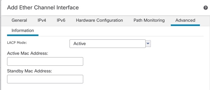
(Optional) Click the Advanced tab to customize the EtherChannel. Set the following parameters on the Information sub-tab:

Figure 5. Advanced
Advanced
  • (ISA 3000 only) Load Balancing—Select the criteria used to load balance the packets across the group channel interfaces. By default, the Firewall Threat Defense device balances the packet load on interfaces according to the source and destination IP address of the packet. If you want to change the properties on which the packet is categorized, choose a different set of criteria. For example, if your traffic is biased heavily towards the same source and destination IP addresses, then the traffic assignment to interfaces in the EtherChannel will be unbalanced. Changing to a different algorithm can result in more evenly distributed traffic. For more information about load balancing, see Load balancing.

  • LACP Mode—Choose Active, Passive, or On. We recommend using Active mode (the default). Passive mode is only available for the ISA 3000 only.

  • (Secure Firewall 3100/4200 only) LACP Rate—Choose Default, Normal, or Fast. The defualt is Normal (also known as slow). Sets the LACP data unit receive rate for a physical interface in the channel group. We recommend that you set the same rate on both sides.

  • (ISA 3000 only) Active Physical Interface: Range—From the left drop-down list, choose the minimum number of active interfaces required for the EtherChannel to be active, between 1 and 16. The default is 1. From the right drop-down list, choose the maximum number of active interfaces allowed in the EtherChannel, between 1 and 16. The default is 16. If your switch does not support 16 active interfaces, be sure to set this command to 8 or fewer.

  • Active MAC Address—Set a manual MAC address if desired. The mac_address is in H.H.H format, where H is a 16-bit hexadecimal digit. For example, the MAC address 00-0C-F1-42-4C-DE is entered as 000C.F142.4CDE.

Step 7

Click the Hardware Configuration tab and set the Duplex and Speed for all member interfaces.

Step 8

Click OK.

Step 9

Click Save.

You can now go to Deploy > Deploy and deploy the policy to assigned devices. The changes are not active until you deploy them.


What to do next

For regular firewall interfaces:

Sync Interface Changes with the Firewall Management Center

Synchronize interface changes to ensure the Firewall Management Center and device configurations remain aligned when physical interfaces are added or removed.

Addition or deletion of physical interfaces on the device can cause the Firewall Management Center and the device to get out of sync. The Firewall Management Center can detect interface changes by one of these methods:

  • Event sent from the device

  • Synchronize when you deploy from the Firewall Management Center

    If the Firewall Management Center detects interface changes when it attempts to deploy, the deployment will fail. You must first accept the interface changes.

  • Manual synchronization

Adding a new interface, or deleting an unused interface has minimal impact on the Firewall Threat Defense configuration. However, deleting an interface that is used in your security policy will impact the configuration. Interfaces can be referenced directly in many places in the Firewall Threat Defense configuration, including access rules, NAT, SSL, identity rules, VPN, DHCP server, and so on. Deleting an interface will delete any configuration associated with that interface. Policies that refer to security zones are not affected. You can also edit the membership of an allocated EtherChannel without affecting the logical device or requiring a sync on the Firewall Management Center.

When the Firewall Management Center detects changes, the Interface page shows status (removed, changed, or added) to the left of each interface.

This procedure describes how to manually sync interface changes if required. If interface changes are temporary, you should not save the changes in the Firewall Management Center; you should wait until the device is stable, and then re-sync.

Before you begin

  • User roles:

    • Admin

    • Access Admin

    • Network Admin

Follow these steps to sync interface changes with the Firewall Management Center:

Procedure


Step 1

Select Devices > Device Management and click Edit (edit icon) for your Firewall Threat Defense device. The Interfaces page is selected by default.

Step 2

If required, click Sync Interfaces on the top left of Interfaces.

Step 3

After the changes are detected, see these steps.

  1. You will see a red banner on Interfaces indicating that the interface configuration has changed. Click the Click to know more link to view the interface changes.

  2. Click Validate Changes to make sure your policy will still work with the interface changes.

    If there are any errors, you need to change your policy and rerun the validation.

  3. Click Save.

    You can now go to Deploy > Deployment and deploy the policy to assigned devices.


Network module management for Secure Firewall 3100/4200

If you install a network module before powering on the device, the network module becomes enabled and ready for use automatically.

Network module management operations

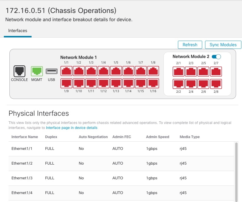
To view physical interface details for the device, and to manage the network module, open the Chassis Operations page. From Devices > Device Management, click Manage in the Chassis column. For clustering or High Availability, this option is only available for the control node/active unit. The Chassis Operations page opens for the device.

Figure 6. Chassis operations
Chassis Operations

Click Refresh to refresh interface status. Click Sync Modules if you made a hardware change on the device that you need to detect.

If you need to make changes to your network module installation after initial bootup, then see the following procedures.

Configure breakout ports

This task configures breakout ports to create smaller ports from 40GB or higher interfaces, allowing you to split a single high-capacity interface into multiple physical Ethernet ports that can be used like any other physical Ethernet port, including being added to EtherChannels.

You can configure smaller breakout ports for each 40GB or higher interface. This procedure tells you how to break out and rejoin the ports. The breakout ports can be used just like any other physical Ethernet port, including being added to EtherChannels. For example, you can break out four 10GB ports from a 40GB interface. The exact size and number of ports depends on your model.

Changes are immediate; you do not need to deploy to the device. After you break or rejoin, you cannot roll back to the previous interface state.

Before you begin

  • You must use a supported breakout cable. See the hardware installation guide for more information.

  • The interface cannot be in use for the following before breaking or rejoining:

    • Failover link

    • Cluster control link

    • Have a subinterface

    • EtherChannel member

    • BVI member

    • Manager access interface

  • Breaking or rejoining an interface that is used directly in your security policy can impact the configuration; however, the action is not blocked.

Follow these steps to configure breakout ports:

Procedure


Step 1

From Devices > Device Management, click Manage in the Chassis column.

For clustering or High Availability, this option is only available for the control node/active unit; network module changes are replicated to all nodes.

Figure 7. Manage chassis
Manage Chassis

The Chassis Operations page opens for the device (in multi-instance mode, this page is called Chassis Manager). This page shows physical interface details for the device.

Step 2

Break out ports from a 40GB or higher interface.

  1. Click Break (break icon) to the right of the interface.

    Click Yes on the confirmation dialog box. If the interface is in use, you will see an error message. You must resolve any use cases before you can retry the breakout.

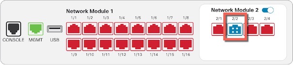
    For example, to break out the Ethernet2/1 40GB interface, the resulting child interfaces will be identified as Ethernet2/1/1, Ethernet2/1/2, Ethernet2/1/3, and Ethernet2/1/4.

    On the interfaces graphic, a port that is broken out has this appearance:

    Figure 8. Breakout ports
    Breakout Ports
  2. Click the link in the message at the top of the screen to go to the Interfaces page to save the interface changes.

    Figure 9. Go to interface page
    Go to Interface Page
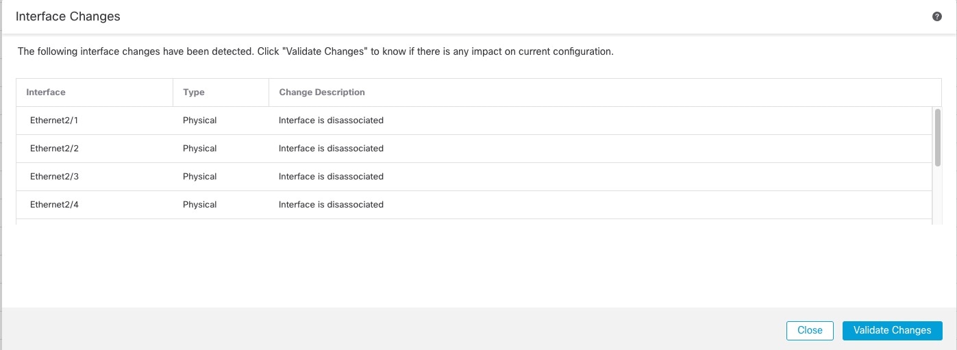
  3. At the top of the Interfaces page, click Click to know more.

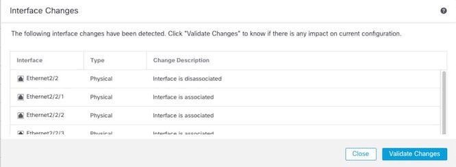
    The Interface Changes dialog box opens.

    Figure 10. View interface changes
    View Interface Changes
    Figure 11. Interface changes
    Interface Changes
  4. Click Validate Changes to make sure your policy will still work with the interface changes.

    If there are any errors, change your policy and rerun the validation.

    Replacing the parent interface that is used in your security policy can impact the configuration. Interfaces can be referenced directly in many places in the configuration, including access rules, NAT, SSL, identity rules, VPN, DHCP server, and so on. Deleting an interface will delete any configuration associated with that interface. Policies that refer to security zones are not affected.

  5. Click Close to return to the Interfaces page.

  6. Click Save to save the interface changes to the firewall.

  7. If you had to change any configuration, go to Deploy > Deployment and deploy the policy.

    You do not need to deploy just to save the breakout port changes.

Step 3

Rejoin breakout ports.

You must rejoin all child ports for the interface.

  1. Click Join (join icon) to the right of the interface.

    Click Yes on the confirmation dialog box. If any child ports are in use, you will see an error message. You must resolve any use cases before you can retry the rejoin.

  2. Click the link in the message at the top of the screen to go to the Interfaces page to save the interface changes.

    Figure 12. Go to interface page
    Go to Interface Page
  3. At the top of the Interfaces page, click Click to know more.

    The Interface Changes dialog box opens.

    Figure 13. View interface changes
    View Interface Changes
    Figure 14. Interface changes
    Interface Changes
  4. Click Validate Changes to make sure your policy will still work with the interface changes.

    If there are any errors, you need to change your policy and rerun the validation.

    Replacing the child interfaces that are used in your security policy can impact the configuration. Interfaces can be referenced directly in many places in the configuration, including access rules, NAT, SSL, identity rules, VPN, DHCP server, and so on. Deleting an interface will delete any configuration associated with that interface. Policies that refer to security zones are not affected.

  5. Click Close to return to the Interfaces page.

  6. Click Save to save the interface changes to the firewall.

  7. If you had to change any configuration, go to Deploy > Deployment and deploy the policy.

    You do not need to deploy just to save the breakout port changes.


Add a network module

This task enables you to add network module functionality to a firewall that is already operational, expanding its interface capabilities.

Adding a new module requires a reboot of the firewall system.

Procedure


Step 1

Install the network module according to the hardware installation guide.

For clustering or High Availability, install the network module on all nodes.

Step 2

Reboot the firewall; see Shut down or restart the device.

For clustering or High Availability, reboot the data nodes/standby unit first, and wait for them to come back up. Then you can change the control node or active unit (see Switch the Active Peer in the Firewall Threat Defense High Availability Pair), and reboot the former control node/active unit.

Step 3

From Devices > Device Management, click Manage in the Chassis column.

For clustering or High Availability, this option is only available for the control node/active unit; network module changes are replicated to all nodes.

Figure 15. Manage chassis
Manage Chassis

The Chassis Operations page opens for the device. This page shows physical interface details for the device.

Step 4

Click Sync Modules to update the page with the new network module details.

Step 5

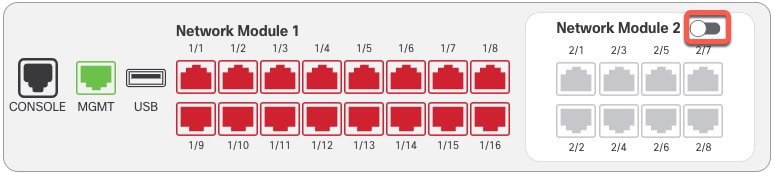
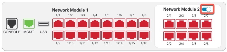
On the interfaces graphic, click the slider (slider disabled) to enable the network module.

Figure 16. Enable the network module
Enable the Network Module

Step 6

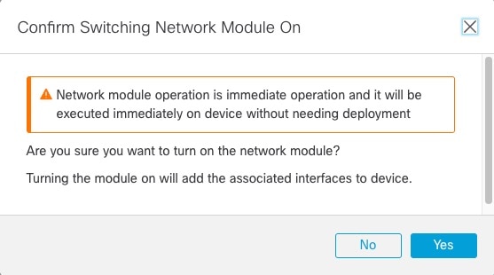
You are prompted to confirm that you want to turn the network module on. Click Yes.

Figure 17. Confirm enable
Confirm Enable

Step 7

You see a message at the top of the screen; click the link to go to the Interfaces page to save the interface changes.

Figure 18. Go to interface page
Go to Interface Page

Step 8

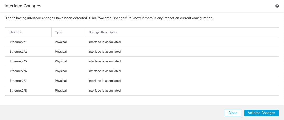
(Optional) At the top of the Interfaces page, you see a message that the interface configuration has changed. You can click Click to know more to open the Interface Changes dialog box to view the changes.

Figure 19. View interface changes
View Interface Changes
Figure 20. Interface changes
Validate Changes

Click Close to return to the Interfaces page. (Because you are adding a new module, there shouldn't be any configuration impact, so you do not need to click Validate Changes.)

Step 9

Click Save to save the interface changes to the firewall.


Hot swap the network module

You can hot swap a network module for a new module of the same type without having to reboot.

You must shut down the current module to remove it safely. This procedure describes how to shut down the old module, install a new module, and enable it.

For clustering or High Availability, you can only perform chassis operations on the control node/active unit. You cannot disable a network module if the cluster control link/failover link is on the module.

Procedure


Step 1

For clustering or High Availability, perform the following steps.

  • Clustering—Ensure the unit you want to perform the hot swap on is a data node; then break the node so it is no longer in the cluster.

    You will add the node back to the cluster after you perform the hot swap. Alternatively, you can perform all operations on the control node, and the network module changes will sync to all data nodes. However, you will lose use of those interfaces on all nodes during the hot swap.

  • High Availability—To avoid failing over when you disable the network module:

Step 2

From Devices > Device Management, click Manage in the Chassis column.

For clustering or High Availability, this option is only available for the control node/active unit; network module changes are replicated to all nodes.

Figure 21. Manage chassis
Manage Chassis

The Chassis Operations page opens for the device. This page shows physical interface details for the device.

Step 3

On the interfaces graphic, click the slider (slider enabled) to disable the network module.

Figure 22. Disable the network module
Disable the Network Module

Do not save any changes on the Interfaces page. Because you are replacing the network module, you do not want to disrupt any existing configuration.

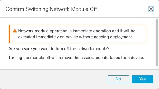
Step 4

You are prompted to confirm that you want to turn the network module off. Click Yes.

Figure 23. Confirm disable
Confirm Disable

Step 5

On the device, remove the old network module and replace it with the new network module according to the hardware installation guide.

Step 6

In the Firewall Management Center, enable the new module by clicking the slider (slider disabled).

Figure 24. Enable the network module
Enable the Network Module

Step 7

You are prompted to confirm that you want to turn the network module on. Click Yes.

Figure 25. Confirm enable
Confirm Enable

Step 8

For clustering or High Availability, perform the following steps.


Replace the network module with a different type

Replace an existing network module with a different type to accommodate new interface requirements or hardware upgrades.

If you replace a network module with a different type, then a reboot is required. If the new module has fewer interfaces than the old module, you will have to manually remove any configuration related to interfaces that will no longer be present.

For clustering or High Availability, you can only perform chassis operations on the control node or active unit.

Before you begin

For High Availability, you cannot disable a network module if the failover link is on the module. You will have to break the high availability pair (see Break a high availability pair), which means you will have downtime when you reboot the active unit. After the units finish rebooting, you can reform High Availability.

Follow these steps to replace the network module with a different type:

Procedure


Step 1

For clustering or High Availability, perform the following steps.

  • Clustering—To avoid downtime, you can break each node one at a time so it is no longer in the cluster when you perform the network module replacement.

    Add the node back to the cluster after the replacement.

  • High Availability—To avoid failing over when you replace the network module, disable interface monitoring for interfaces on the network module. See Configure standby IP addresses and interface monitoring.

Step 2

From Devices > Device Management, click Manage in the Chassis column.

For clustering or High Availability, this option is only available for the control node/active unit; network module changes are replicated to all nodes.

Figure 26. Manage chassis
Manage Chassis

The Chassis Operations page opens for the device. This page shows physical interface details for the device.

Step 3

On the interfaces graphic, click the slider (slider enabled) to disable the network module.

Figure 27. Disable the network module
Disable the Network Module

Do not save any changes on the Interfaces page. Because you are replacing the network module, you do not want to disrupt any existing configuration.

  1. You are prompted to confirm that you want to turn the network module off. Click Yes.

    Figure 28. Confirm disable
    Confirm Disable

Step 4

On the device, remove the old network module and replace it with the new network module according to the hardware installation guide.

Reboot the firewall. Refer to Shut down or restart the device for guidance.

For clustering or High Availability, reboot the data nodes/standby unit first, and wait for them to come back up. Then you can change the control node or active unit (see Switch the Active Peer in the Firewall Threat Defense High Availability Pair), and reboot the former control node/active unit.

Step 5

In the Firewall Management Center, click Sync Modules to update the page with the new network module details.

Step 6

Enable the new module by clicking the slider (slider disabled).

Figure 29. Enable the network module
Enable the Network Module
  1. Click Yes when prompted to confirm that you want to turn the network module on.

    Figure 30. Confirm enable
    Confirm Enable

Step 7

Click the link in the message at the top of the screen to go to the Interfaces page to save the interface changes.

Figure 31. Go to interface page
Go to Interface Page

Step 8

If the network module has fewer interfaces:

  1. At the top of the Interfaces page, click Click to know more.

    The Interface Changes dialog box opens.

    Figure 32. View interface changes
    View Interface Changes
    Figure 33. Interface changes
    Interface Changes
  2. Click Validate Changes to make sure your policy will still work with the interface changes.

    If there are any errors, you need to change your policy and rerun the validation.

    Deleting an interface that is used in your security policy can impact the configuration. Interfaces can be referenced directly in many places in the configuration, including access rules, NAT, SSL, identity rules, VPN, DHCP server, and so on. Deleting an interface will delete any configuration associated with that interface. Policies that refer to security zones are not affected.

  3. Click Close to return to the Interfaces page.

Step 9

To change the interface speed, see Enable the physical interface and configure Ethernet settings.

The default speed is set to Detect SFP, which detects the correct speed from the SFP installed. You only need to fix the speed if you manually set the speed to a particular value and you now need a new speed.

Click Save to save the interface changes to the firewall.


What to do next

  • If you had to change any configuration, go to Deploy > Deployment and deploy the policy.

  • For clustering, add the node back to the cluster.

  • For high availability, reenable interface monitoring for interfaces on the network module. See Configure standby IP addresses and interface monitoring.

Remove the network module

Remove a network module permanently from the chassis when it is no longer needed or requires replacement.

If you want to permanently remove the network module, follow these steps. Removing a network module requires a reboot.

For clustering or High Availability, you can only perform chassis operations on the control node or active unit.

Before you begin

For clustering or High Availability, make sure the cluster or failover link is not on the network module.

Procedure


Step 1

From Devices > Device Management, click Manage in the Chassis column.

For clustering or High Availability, this option is only available for the control node/active unit; network module changes are replicated to all nodes.

Figure 34. Manage chassis
Manage Chassis

The Chassis Operations page opens for the device. This page shows physical interface details for the device.

Step 2

On the interfaces graphic, click the slider (slider enabled) to disable the network module.

Figure 35. Disable the network module
Disable the Network Module

Step 3

You are prompted to confirm that you want to turn the network module off. Click Yes.

Figure 36. Confirm disable
Confirm Disable

Step 4

You see a message at the top of the screen; click the link to go to the Interfaces page to save the interface changes.

Figure 37. Go to interface page
Go to Interface Page

Step 5

At the top of the Interfaces page, you see a message that the interface configuration has changed.

Figure 38. View interface changes
View Interface Changes
  1. Click Click to know more to open the Interface Changes dialog box to view the changes.

    Figure 39. Interface changes
    Interface Changes
  2. Click Validate Changes to make sure your policy will still work with the interface changes.

    If there are any errors, you need to change your policy and rerun the validation.

    Deleting an interface that is used in your security policy can impact the configuration. Interfaces can be referenced directly in many places in the configuration, including access rules, NAT, SSL, identity rules, VPN, DHCP server, and so on. Deleting an interface will delete any configuration associated with that interface. Policies that refer to security zones are not affected.

  3. Click Close to return to the Interfaces page.

Step 6

Click Save to save the interface changes to the firewall.

Step 7

If you had to change any configuration, go to Deploy > Deployment and deploy the policy.

Step 8

Reboot the firewall; see Shut down or restart the device.

For clustering or High Availability, reboot the data nodes/standby unit first, and wait for them to come back up. Then you can change the control node or active unit (see Switch the Active Peer in the Firewall Threat Defense High Availability Pair), and reboot the former control node/active unit.


Merge the management and diagnostic interfaces

This task merges the Management and Diagnostic interfaces on devices that have existing Diagnostic interface configurations that prevent automatic merging.

Starting with version 7.4, Firewall Threat Defense supports a merged Management and Diagnostic interface. "If your configuration uses the Diagnostic interface, the interfaces are not merged automatically. You must perform this procedure to complete the merge. This procedure requires you to acknowledge configuration changes and, in some cases, manually fix the configuration.

The Backup/Restore and Firewall Management Center configuration rollback functions save and restore the merged state, whether it is non-merged or merged. For example, if you merge the interfaces and then restore an old non-merged configuration, the restored configuration will be in a non-merged state.

This table shows the available configuration on the legacy Diagnostic interface, and how the merge is completed.

Before you begin

  • To view the current mode of the device, enter the show management-interface convergence command at the Firewall Threat Defense CLI. The following output shows that the Management interfaces are merged:

    
    > show management-interface convergence
    management-interface convergence
    >
    

    The following output shows that the Management interfaces are not merged:

    
    > show management-interface convergence
    no management-interface convergence
    >
    
  • For High Availability pairs and clusters, perform this task on the active/control unit. The merged configuration will be replicated automatically to the standby/data units.

Follow these steps to merge the Management and Diagnostic interfaces:

Procedure


Step 1

Choose Devices > Device Management, and click Edit (edit icon) for your Firewall Threat Defense. The Interfaces page is selected by default. .

Step 2

Edit the Diagnostic interface, and remove the IP address.

You cannot complete the merge until after you have removed the Diagnostic IP address.

Step 3

Click Management Interface Merge in the Management Interface action needed area.

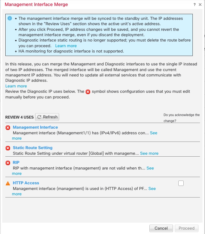
The Management Interface Merge dialog box shows all the occurrences of the Diagnostic interface in the configuration. For any occurrences that require you to manually remove or change the configuration, they will appear with a warning icon. Platform Settings that will no longer work on your device are marked with a caution icon and require your acknowledgement.

The Management Interface Merge dialog box displays occurrences of the Diagnostic interface in the configuration, highlighting those that need manual removal or changes with warning icons. Platform Settings that are incompatible with your device are indicated by caution icons.

Step 4

If you need to manually remove or change any listed configurations, do the following.

  1. Click Cancel to close the Management Interface Merge dialog box.

  2. Navigate to the feature area. You can then delete the item, or choose a data interface instead.

  3. Reopen the Management Interface Merge dialog box.

    There should no longer be any warnings.

Step 5

For each configuration caution, click the box in Do you acknowledge the change? column, and then click Proceed.

The success banner indicates that the configuration merge was completed without any warnings.

After the configuration is merged, you see a success banner:

The success banner indicates that the configuration merge was completed without any warnings.

Step 6

Deploy the new merged configuration.

Caution


After you deploy the merged configuration, you can unmerge the interfaces from Firewall Management Center; however the Diagnostic interface will have to be reconfigured manually. See Unmerge the management interface. Also, if you restore a configuration that is unmerged, or roll back to an unmerged configuration, then the device will revert to that unmerged configuration.

After the merge, the Management interface is shown on the Interfaces page, although it is read-only.

Step 7

After the merge, if you had any external services that communicated with the Diagnostic interface, you need to change their configuration to use the Management interface IP address.

For example:

  • SNMP client

  • RADIUS server—RADIUS servers often verify the IP address for incoming traffic, so you need to change that IP address to the Management address. Moreover, for a High Availability pair, you need to allow both the primary and secondary Management IP addresses; the Diagnostic interface used to support a single "floating" IP address that stayed with the active unit, but Management does not support that functionality.


Unmerge the management interface

This task separates the merged Management and Diagnostic interface into two distinct interfaces. This is useful when migrating network configurations or when separate interface management is required for specific network architectures.

The Firewall Threat Defense 7.4 and later supports a merged Management and Diagnostic interface. If you need to unmerge your interfaces, perform this procedure. We recommend using unmerged mode temporarily while you migrate your network to a merged mode deployment. Separate Management and Diagnostic interfaces may not be supported in all future releases.

Unmerging the interfaces does not restore your original Diagnostic configuration (if you upgraded and then merged your interfaces). You will need to reconfigure the Diagnostic interface manually. Also, the Management interface will now be named "management"; you cannot rename it "diagnostic."

Alternatively, if you used the Backup function to save an old unmerged configuration, you can restore that configuration or you can use the or Firewall Management Center configuration rollback feature, and the device will be in an unmerged state with the Diagnostic configuration intact.

Before you begin

  • To view the current mode of the device, enter the show management-interface convergence command at the Firewall Threat Defense CLI. The following output shows that the Management interfaces are merged:

    
    > show management-interface convergence
    management-interface convergence
    >                   
    

    The following output shows that the Management interfaces are not merged:

    
    > show management-interface convergence
    no management-interface convergence
    >                   
    
  • For High Availability pairs and clusters, perform this task on the active/control unit. The merged configuration will be replicated automatically to the standby/data units.

Follow these steps to unmerge the Management Interface:

Procedure


Step 1

Choose Devices > Device Management, and click Edit (edit icon) for your Firewall Threat Defense. The Interfaces page is selected by default.

Step 2

For the Management interface, click Unmerge Management Interface (Unmerge Management Interface).

Figure 40. Management interface selection
Management Interface Selection

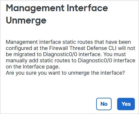
Step 3

Click Yes to confirm that you want to unmerge the interface.

Figure 41. Unmerge confirmation
Unmerge Confirmation

Step 4

Deploy the new unmerged configuration.

Note


If you restore a configuration that is merged, or roll back to a merged configuration, then the device will revert to that merged configuration.

After the merge, the Management interface is no longer shown on the Interfaces page.


History for interfaces

This reference provides the complete version history for interface-related features, enhancements, and changes across different versions of the Secure Firewall system.

Feature

Minimum Firewall Management Center

Minimum Firewall Threat Defense

Details

Sync Device is now called Sync Interfaces

7.7.0

7.7.0

Sync Device was changed to Sync Interfaces to indicate that this function is only for interface changes. This function no longer detects changes made to the manager access interface; see Devices > Device Management > Device > Management > Manager Access Details: Configuration.

Other out-of-band configuration changes performed at the diagnostic CLI in recovery-config mode need to be discovered at Devices > Device Management > Device > Health > Out of Band Status.

New/Modified screens: Devices > Device Management > Interfaces

Loopback and Management type interface group objects

7.4.0

7.4.0

You can now create interface group objects that include only management-only interfaces or only loopback interfaces. You can then use these groups for management features such as DNS servers, HTTP access, or SSH. Loopback groups are supported for any feature that supports loopback interfaces. Note that DNS does not support management interfaces.

New/Modified screens: Objects > Object Management > Interface > Add > Interface Group

Merged Management and Diagnostic interfaces

7.4.0

7.4.0

For new devices using 7.4 and later, you cannot use the legacy Diagnostic interface. Only the merged Management interface is available. If you upgraded to 7.4 or later, and you did not have any configuration for the Diagnostic interface, then the interfaces will merge automatically.

If you upgraded to 7.4 or later, and you have configuration for the Diagnostic interface, then you have the choice to merge the interfaces manually, or you can continue to use the separate Diagnostic interface. Note that support for the Diagnostic interface will be removed in a later release, so you should plan to merge the interfaces as soon as possible.

Merged mode also changes the behavior of AAA traffic to use the data routing table by default. The management-only routing table can now only be used if you specify the management-only interface (including Management) in the configuration.

New/Modified screens: Devices > Device Management > Interfaces

New/Modified commands: show management-interface convergence

Default Forward Error Correction (FEC) on Secure Firewall 3100 fixed ports changed to Clause 108 RS-FEC from Clause 74 FC-FEC for 25 GB+ SR, CSR, and LR transceivers

7.2.4

7.2.4

When you set the FEC to Auto on the Secure Firewall 3100 fixed ports, the default type is now set to Clause 108 RS-FEC instead of Clause 74 FC-FEC for 25 GB+ SR, CSR, and LR transceivers.

LLDP support for the Firepower 2100, Secure Firewall 3100

7.2.0

7.2.0

You can enable Link Layer Discovery Protocol (LLDP) for Firepower 2100 and Secure Firewall 3100 interfaces.

New/Modified screens:

Devices > Device Management > Interfaces > Hardware Configuration > Network Connectivity

New/Modified commands: show LLDP status, show LLDP neighbors, show LLDP statistics

Pause Frames for Flow Control for the Secure Firewall 3100

7.2.0

7.2.0

If you have a traffic burst, dropped packets can occur if the burst exceeds the buffering capacity of the FIFO buffer on the NIC and the receive ring buffers. Enabling pause frames for flow control can alleviate this issue.

New/Modified screens: Devices > Device Management > Interfaces > Hardware Configuration > Network Connectivity

Support for hot swapping the network module for the Secure Firewall 3100

7.1.0

7.1.0

You can add or remove the network module on the Secure Firewall 3100 while the firewall is powered up. To replace a module with another module of the same type, you do not need to reboot. After initial bootup, adding a module, permanently removing a module, or replacing a module with a new type requires a reboot.

New/Modified screens:

Devices > Device Management > Chassis Operations

Support for Forward Error Correction for the Secure Firewall 3100

7.1.0

7.1.0

Secure Firewall 3100 25 Gbps interfaces support Forward Error Correction (FEC). FEC is enabled by default and set to Auto.

New/Modified screens: Devices > Device Management > Interfaces > Edit Physical Interface > Hardware Configuration

Support for setting the speed based on the SFP for the Secure Firewall 3100

7.1.0

7.1.0

The Secure Firewall 3100 supports speed detection for interfaces based on the SFP installed. Detect SFP is enabled by default. This option is useful if you later change the network module to a different model, and want the speed to update automatically.

New/Modified screens: Devices > Device Management > Interfaces > Edit Physical Interface > Hardware Configuration

LLDP support for the Firepower 1100.

7.1.0

7.1.0

You can enable Link Layer Discovery Protocol (LLDP) for Firepower 1100 interfaces.

New/Modified screens: Devices > Device Management > Interfaces > Hardware Configuration > LLDP

New/Modified commands: show LLDP status, show LLDP neighbors, show LLDP statistics

Interface auto-negotiation is now set independently from speed and duplex, interface sync improved.

7.1.0

7.1.0

Interface auto-negotiation is now set independently from speed and duplex. Also, when you sync the interfaces in Firewall Management Center, hardware changes are detected more effectively.

New/Modified screens: Devices > Device Management > Interfaces > Hardware Configuration > Speed

Supported platforms: Firepower 1000, 2100, Secure Firewall 3100

Firepower 1100/2100 series fiber interfaces now support disabling auto-negotiation.

6.7.0

6.7.0

You can now configure a Firepower 1100/2100 series fiber interface to disable flow control and link status negotiation.

Previously, when you set the fiber interface speed (1000 or 10000 Mbps) on these devices, flow control and link status negotiation was automatically enabled. You could not disable it.

Now, you can deselect Auto-negotiation and set the speed to 1000 to disable flow control and link status negotiation. You cannot disable negotiation at 10000 Mbps.

New/modified screens: Devices > Device Management > Interfaces > Hardware Configuration > Speed