Regular Firewall Interfaces

This chapter includes regular firewall Firewall Threat Defense interface configuration including EtherChannels, VLAN subinterfaces, IP addressing, and more.


Note


For initial interface configuration on the Firepower 4100/9300, see Configure Interfaces.


Requirements and prerequisites for regular firewall interfaces

This reference provides the requirements and prerequisites for configuring regular firewall interfaces, including supported models and required user roles.

Model support

Firewall Threat Defense

User roles

  • Admin

  • Access Admin

  • Network Admin

Configure switch ports

For supported platforms, you can configure each interface to run as a regular firewall interface or as a Layer 2 hardware switch port. This section includes tasks for starting your switch port configuration, including enabling or disabling the switch mode and creating VLAN interfaces and assigning them to switch ports. This section also describes how to customize Power over Ethernet (PoE) on supported interfaces.

About switch ports

This section describes the switch ports for models with Layer 2 switches.

Switch ports and interfaces

Switch ports and firewall operate at different OSI layers to handle traffic forwarding.

Port and interface types

For each physical interface, you can set its operation as a firewall interface or as a switch port. This information describes physical interface and port types as well as logical VLAN interfaces to which you assign switch ports:

  • Physical firewall interface—In routed mode, these interfaces forward traffic between networks at Layer 3, using the configured security policy to apply firewall and VPN services. In transparent mode, these interfaces are bridge group members that forward traffic between the interfaces on the same network at Layer 2, using the configured security policy to apply firewall services. In routed mode, you can also use Integrated Routing and Bridging with some interfaces as bridge group members and others as Layer 3 interfaces. By default, the Ethernet 1/1 interface is configured as a firewall interface. You can also configure these interfaces to be IPS-only (passive interfaces).

  • Physical switch port—Switch ports forward traffic at Layer 2, using the switching function in hardware. Switch ports on the same VLAN can communicate with each other using hardware switching, and traffic is not subject to the Firewall Threat Defense security policy. Access ports accept only untagged traffic, and you can assign them to a single VLAN. Trunk ports accept untagged and tagged traffic, and can belong to more than one VLAN. By default, Ethernet 1/2 and subsequent ports are configured as access switch ports on VLAN 1. You cannot configure the Diagnostic interface as a switch port.

  • Logical VLAN interface—These interfaces operate the same as physical firewall interfaces, with the exception that you cannot create subinterfaces, IPS-only interfaces (inline sets and passive interfaces), or EtherChannel interfaces. When a switch port needs to communicate with another network, then the Firewall Threat Defense device applies the security policy to the VLAN interface and routes to another logical VLAN interface or firewall interface. You can even use Integrated Routing and Bridging with VLAN interfaces as bridge group members. Traffic between switch ports on the same VLAN are not subject to the Firewall Threat Defense security policy, but traffic between VLANs in a bridge group are subject to the security policy, so you may choose to layer bridge groups and switch ports to enforce the security policy between certain segments.

Power Over Ethernet

PoE is available on Ethernet 1/7 and Ethernet 1/8 using IEEE 802.3af (PoE) and 802.3at (PoE+) up to 30 watts per port.


Note


PoE is not supported on the 1010E.


PoE+ uses Link Layer Discovery Protocol (LLDP) to negotiate the power level. Power is only supplied when needed.

If you shut down the interface, then you disable power to the device.

Auto-MDI/MDIX feature

Auto-MDI/MDIX eliminates the need for crossover cabling by performing an internal crossover when a straight cable is detected during the auto-negotiation phase.

Auto-MDI/MDIX configuration details

For all switch ports, the default auto-negotiation setting also includes the Auto-MDI/MDIX feature. The interface enables Auto-MDI/MDIX when either the speed or duplex is set to auto-negotiate. If you set both the speed and duplex to fixed values, auto-negotiation is disabled, and Auto-MDI/MDIX is also disabled. When the speed and duplex are set to 1000 and full, the interface always auto-negotiates. Auto-MDI/MDIX enabled in this state, and disabling it is not possible.

Prerequisites for switch ports

This reference provides model support and other prerequisites for switch ports.

Model support

  • Firepower 1010

Guidelines for switch ports

Context mode restrictions

Multiple context mode is not supported on several firewall models, with specific exceptions for the Secure Firewall 1210/1220.

  • The Firepower 1010 does not support multiple context mode.

  • The Secure Firewall 1210/1220 does not support multiple context mode.

High availability and clustering limitations

Do not use switch port functionality when using High availability because switch ports operate in hardware and continue to pass traffic on both active and standby units.

  • No cluster support.

  • Because the switch ports operate in hardware, they continue to pass traffic on both the active and the standby units. High availability is designed to prevent traffic from passing through the standby unit, but this feature does not extend to switch ports. In a normal High availability network setup, active switch ports on both units will lead to network loops. We suggest that you use external switches for any switching capability. Note that VLAN interfaces can be monitored by failover, while switch ports cannot. Theoretically, you can put a single switch port on a VLAN and successfully use High availability, but a simpler setup is to use physical firewall interfaces instead.

  • You can only use a firewall interface as the failover link.

Logical VLAN interfaces (SVIs) configuration requirements

Ensure unique VLAN IDs between logical VLAN interfaces and VLAN subinterfaces on firewall interfaces to prevent conflicts.

  • If you also use VLAN subinterfaces on a firewall interface, you cannot use the same VLAN ID as for a logical VLAN interface.

  • MAC Addresses:

    • Routed firewall mode—All VLAN interfaces share a MAC address. Ensure that any connected switches can support this scenario. If the connected switches require unique MAC addresses, you can manually assign MAC addresses. See Configure the MAC address.

    • Transparent firewall mode—Each VLAN interface has a unique MAC address. You can override the generated MAC addresses if desired by manually assigning MAC addresses. See Configure the MAC address.

Bridge groups restrictions

You cannot mix logical VLAN interfaces and physical firewall interfaces in the same bridge group.

VLAN interface and switch port unsupported features

VLAN interfaces and switch ports do not support these features.

  • Dynamic routing

  • Multicast routing

  • Equal-Cost Multi-Path routing (ECMP)

  • Inline sets or Passive interfaces

  • EtherChannels—Switch ports cannot be part of an EtherChannel. PoE is also not supported on a port in an EtherChannel.

  • Failover and state link

  • Security group tagging (SGT)

Other guidelines and limitations

Configure a maximum of 60 named interfaces and ensure the Diagnostic interface is not configured as a switch port.

Default settings

Know the default interface assignments for each firewall model to properly plan your configuration.

  • Ethernet 1/1 is a firewall interface.

  • Ethernet 1/2 through Ethernet 1/8 are switch ports assigned to VLAN 1.

  • Default Speed and Duplex—By default, the speed and duplex are set to auto-negotiate.

Configure switch ports and power over ethernet

To configure switch ports and PoE, complete the following tasks.

Enable or disable switch port mode

Set each interface independently to be either a firewall interface or a switch port based on your network requirements.

You can set each interface independently to be either a firewall interface or a switch port. By default, Ethernet 1/1 is a firewall interface, and the remaining Ethernet interfaces are configured as switch ports.

Procedure

Step 1

Select Devices > Device Management and click Edit (edit icon) for your Firewall Threat Defense device. The Interfaces page is selected by default.

Step 2

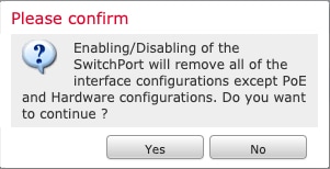
Set the switch port mode by clicking the slider in the SwitchPort column so it shows as Slider enabled (slider enabled) or Slider disabled (slider disabled).

By default, switch ports are set to access mode in VLAN 1. You must manually add a logical VLAN 1 interface (or whichever VLAN you set for these switch ports) for traffic to be routed and to participate in the Firewall Threat Defense security policy (see Configure a VLAN interface). You cannot set the Management interface to switch port mode. When you change the switch port mode, all unsupported configuration is removed:

The image illustrates the process of enabling or disabling switch port mode, highlighting the configuration options and implications for VLAN settings and interface management.

In addition, the interface is disabled if it was already enabled. Be sure to reenable the interface.


Configure a VLAN interface

Configure VLAN interfaces to enable traffic routing and participation in the Firewall Threat Defense security policy.

By default, switch ports are assigned to VLAN1; however, you must manually add the logical VLAN1 interface (or whichever VLAN you set for these switch ports) for traffic to be routed and to participate in the Firewall Threat Defense security policy.

Procedure

Step 1

Select Devices > Device Management and click Edit (edit icon) for your Firewall Threat Defense device. The Interfaces page is selected by default.

Step 2

Click Add Interfaces > VLAN Interface.

Step 3

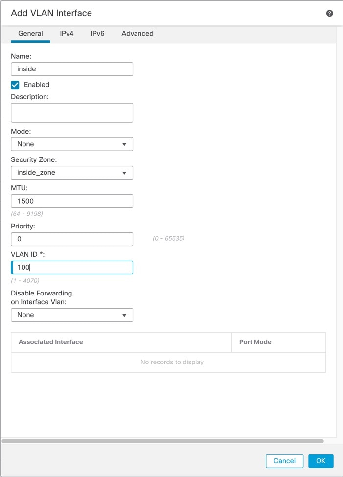
On General, set the following VLAN-specific parameters:

The Associated Interface table displays the switch ports linked to the VLAN interface being edited, highlighting the VLAN ID and its role in the configuration.

If you are editing an existing VLAN interface, the Associated Interface table shows switch ports on this VLAN.

  1. Set the VLAN ID between 1 and 4070, excluding IDs in the range 3968 to 4047, which are reserved for internal use.

    You cannot change the VLAN ID after you save the interface; the VLAN ID is both the VLAN tag used, and the interface ID in your configuration.

  2. (Optional) Choose a VLAN ID for Disable Forwarding on Interface VLAN to disable forwarding to another VLAN.

    For example, you have one VLAN assigned to the outside for internet access, one VLAN assigned to an inside business network, and a third VLAN assigned to your home network. The home network does not need to access the business network, so you can disable forwarding on the home VLAN. The business network can access the home network, but the home network cannot access the business network.

Step 4

To complete the interface configuration, see one of these procedures:

Step 5

Click OK.

Step 6

Click Save.

You can now go to Deploy > Deploy and deploy the policy to assigned devices. The changes are not active until you deploy them.


Configure switch ports as access ports

Configure switch ports as access ports to assign them to a single VLAN for network segmentation and traffic management.

To assign a switch port to a single VLAN, configure it as an access port. Access ports accept only untagged traffic. By default, Ethernet 1/2 through Ethernet 1/8 switch ports are enabled and assigned to VLAN 1.


Note


The device does not support Spanning Tree Protocol for loop detection in the network. Therefore you must ensure that any connection with the Firewall Threat Defense does not end up in a network loop.


Procedure

Step 1

Select Devices > Device Management and click Edit (edit icon) for your Firewall Threat Defense device. The Interfaces page is selected by default.

Step 2

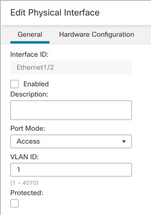
Click Edit (edit icon) for the interface you want to edit.

Figure 1. Edit physical interface
Edit Physical Interface

Step 3

Enable the interface by checking the Enabled check box.

Step 4

(Optional) Add a description in the Description field.

The description can be up to 200 characters on a single line, without carriage returns.

Step 5

Set the Port Mode to Access.

Step 6

In the VLAN ID field, set the VLAN for this switch port, between 1 and 4070.

The default VLAN ID is 1.

Step 7

(Optional) Check the Protected check box to set this switch port as protected, so you can prevent the switch port from communicating with other protected switch ports on the same VLAN.

You might want to prevent switch ports from communicating with each other if: the devices on those switch ports are primarily accessed from other VLANs; you do not need to allow intra-VLAN access; and you want to isolate the devices from each other in case of infection or other security breach. For example, if you have a DMZ that hosts three web servers, you can isolate the web servers from each other if you enable Protected on each switch port. The inside and outside networks can both communicate with all three web servers, and vice versa, but the web servers cannot communicate with each other.

Step 8

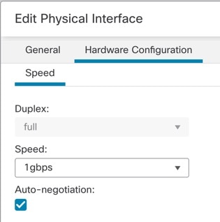
(Optional) Set the duplex and speed by clicking Hardware Configuration.

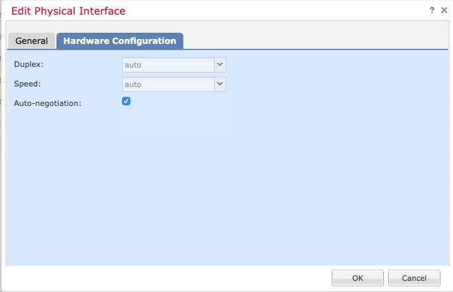
Figure 2. Hardware configuration
Hardware Configuration

Check the Auto-negotiation check box (the default) to auto-detect the speed and duplex. If you uncheck it, you can set the speed and duplex manually:

  • Duplex—Choose Full or Half.

  • Speed—Choose 10mbps, 100mbps, or 1gbps.

Note


If a peer switch connecting to the port over a 50G cable does not support auto-negotiation, ensure to disable auto-negotiation on the switch and the Threat Defense interface as well. For example, N9K-C93400LD-H1 does not support auto-negotiation on a 50G cable. Hence, you must disable the default auto-negotiation on the platform and the switch for the port to be connected.

Step 9

Click OK.

Click Save.


What to do next

Go to Deploy > Deploy and deploy the policy to assigned devices. The changes are not active until you deploy them.

Configure switch ports as trunk ports

This task creates a trunk port that can carry multiple VLANs using 802.1Q tagging.

This procedure describes how to create a trunk port that can carry multiple VLANs using 802.1Q tagging. Trunk ports accept untagged and tagged traffic. Traffic on allowed VLANs pass through the trunk port unchanged.

When the trunk receives untagged traffic, it tags it to the native VLAN ID so that the Firewall Threat Defense device can forward the traffic to the correct switch ports or can route it to another firewall interface. When the Firewall Threat Defense device sends native VLAN ID traffic out of the trunk port, it removes the VLAN tag. Be sure to set the same native VLAN on the trunk port on the other switch so that the untagged traffic will be tagged to the same VLAN.

Procedure

Step 1

Select Devices > Device Management and click Edit (edit icon) for your Firewall Threat Defense device. The Interfaces page is selected by default.

Step 2

Click Edit (edit icon) for the interface you want to edit.

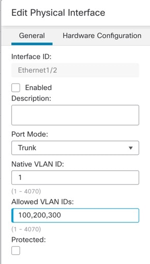
Figure 3. Set trunk port mode
Set Trunk Port Mode

Step 3

Enable the interface by checking the Enabled check box.

Step 4

(Optional) Add a description in the Description field.

The description can be up to 200 characters on a single line, without carriage returns.

Step 5

Set the Port Mode to Trunk.

Step 6

Set the VLAN IDs:

  1. In the Native VLAN ID field, set the native VLAN for this switch port, between 1 and 4070.

    The default native VLAN ID is 1.

    Each port can only have one native VLAN, but every port can have either the same or a different native VLAN.

  2. In the Allowed VLAN IDs field, enter the VLANs for this trunk port between 1 and 4070.

    You can identify up to 20 IDs in one of these ways:

    • A single number (n)

    • A range (n-x)

    • Numbers and ranges separated by commas, for example:

      5,7-10,13,45-100

      You can enter spaces instead of commas.

    If you include the native VLAN in this field, it is ignored; the trunk port always removes the VLAN tagging when sending native VLAN traffic out of the port. Moreover, it will not receive traffic that still has native VLAN tagging.

Step 7

(Optional) Check the Protected check box to set this switch port as protected, so you can prevent the switch port from communicating with other protected switch ports on the same VLAN.

You might want to prevent switch ports from communicating with each other if: the devices on those switch ports are primarily accessed from other VLANs; you do not need to allow intra-VLAN access; and you want to isolate the devices from each other in case of infection or other security breach. For example, if you have a DMZ that hosts three web servers, you can isolate the web servers from each other if you enable Protected on each switch port. The inside and outside networks can both communicate with all three web servers, and vice versa, but the web servers cannot communicate with each other.

Step 8

(Optional) Set the duplex and speed by clicking Hardware Configuration.

The configuration interface for setting switch ports as trunk ports, highlighting options for auto-negotiation, duplex, and speed settings.

Check the Auto-negotiation check box (the default) to auto-detect the speed and duplex. If you uncheck it, you can set the speed and duplex manually:

  • Duplex—Choose Full or Half.

  • Speed—Choose 10mbps, 100mbps, or 1gbps.

If a peer switch connecting to the port over a 50G cable does not support auto-negotiation, ensure to disable auto-negotiation on the switch and the Threat Defense interface as well. For example, N9K-C93400LD-H1 does not support auto-negotiation on a 50G cable. Hence, you must disable the default auto-negotiation on the platform and the switch for the port to be connected.

Step 9

Click OK.

Click Save.


What to do next

Go to Deploy > Deploy and deploy the policy to assigned devices. The changes are not active until you deploy them.

Configure Power over Ethernet

Configure Power over Ethernet (PoE) settings to control power delivery to connected devices and optimize power allocation.

Power over Ethernet (PoE) ports provide power for devices such as IP phones or wireless access points. PoE is enabled by default. This procedure describes how to disable and enable PoE and how to set optional parameters.

Procedure

Step 1

Select Devices > Device Management and click Edit (edit icon) for your Firewall Threat Defense device. The Interfaces page is selected by default.

Step 2

Click Edit (edit icon) for Ethernet1/7 or 1/8 .

Step 3

Click PoE.

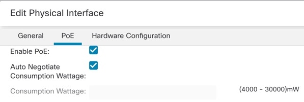
Figure 4. PoE
PoE

Step 4

Check the Enable PoE check box.

PoE is enabled by default.

Step 5

Choose autonegotiation or manual power.

  • Auto Negotiate Consumption Wattage—Delivers power automatically to the powered device using a wattage appropriate to the class of the powered device. The firewall uses LLDP to further negotiate the correct wattage. When you connect a device of a certain class, it will be provisioned up to the maximum for that class in case it ever needs to use more power. For example, if you add a class 4 device that requests 12.95W, it will be allocated 30W even if it doesn't currently use all that power. Some devices can renegotiate power needs. If you know your device needs less power than is allocated, you can instead set the Consumption Wattage manually to free up the power for other devices.

  • Consumption Wattage—Uncheck the Auto Negotiate Consumption Wattage check box to set the manual wattage to manually specify the wattage in milliwatts, from 4000 to 30000. Use this option if you want to set the watts manually and disable LLDP negotiation. For manual allocation, the class will show in show power inline output as n/a because the class is not used to decide the power consumption.

    View the current PoE status using the show power inline command.

Step 6

Click OK.

Step 7

Click Save.

You can now go to Deploy > Deploy and deploy the policy to assigned devices. The changes are not active until you deploy them.


Loopback interfaces

A loopback interface is a software-only interface that emulates a physical interface. This interface is reachable on IPv4 and IPv6 through multiple physical interfaces. The loopback interface helps to overcome path failures. It is accessible from any physical interface. If one interface goes down, you can access the loopback interface from another.

Loopback interfaces can be used for:

The Firewall Threat Defense can distribute the loopback address using dynamic routing protocols, or you can configure a static route on the peer device to reach the loopback IP address through one of the Firewall Threat Defense's physical interfaces. You cannot configure a static route on the Firewall Threat Defense that specifies the loopback interface.

Guidelines for Loopback Interfaces

This topic outlines the specific constraints and supported configurations for loopback interfaces in various network environments.

Firewall Mode

High availability and Clustering

  • No clustering support.

Additional Guidelines and Limitations

  • TCP sequence randomization is always disabled for traffic from the physical interface to the loopback interface.

Configure a loopback interface

Configure a loopback interface to provide a virtual interface that remains active regardless of physical interface status, commonly used for routing protocols and management purposes.

Loopback interfaces are virtual interfaces that provide stable IP addresses for device management and routing protocols. They remain active as long as the device is operational, making them ideal for network management tasks.

Before you begin

Follow these steps to add a loopback interface for a device:

Procedure


Step 1

Select Devices > Device Management and click Edit (edit icon) for your Firewall Threat Defense device. The Interfaces page is selected by default.

Step 2

From the Add Interfaces drop-down list, choose Loopback Interface.

Step 3

In the General tab, configure the following parameters:

  1. Name—Enter a name for the loopback interface.

  2. Enabled—Check the check box to enable the loopback interface.

  3. Loopback ID—Enter the loopback ID between 1 to 1024.

  4. Description—Enter a description for the loopback interface.

Step 4

Configure the routed mode interface parameters. See Configure routed mode interfaces.


Rate-Limit traffic to the loopback interface

You should rate-limit traffic going to the loopback interface IP address to prevent excessive load on the system. You can add a connection limit rule to the global service policy.

Rate-limiting protects the system from Denial of Service (DoS) attacks and ensures stable performance by controlling the number of connections to critical interface addresses.

Before you begin

Follow these steps to rate-limit traffic to the loopback interface:

Procedure


Step 1

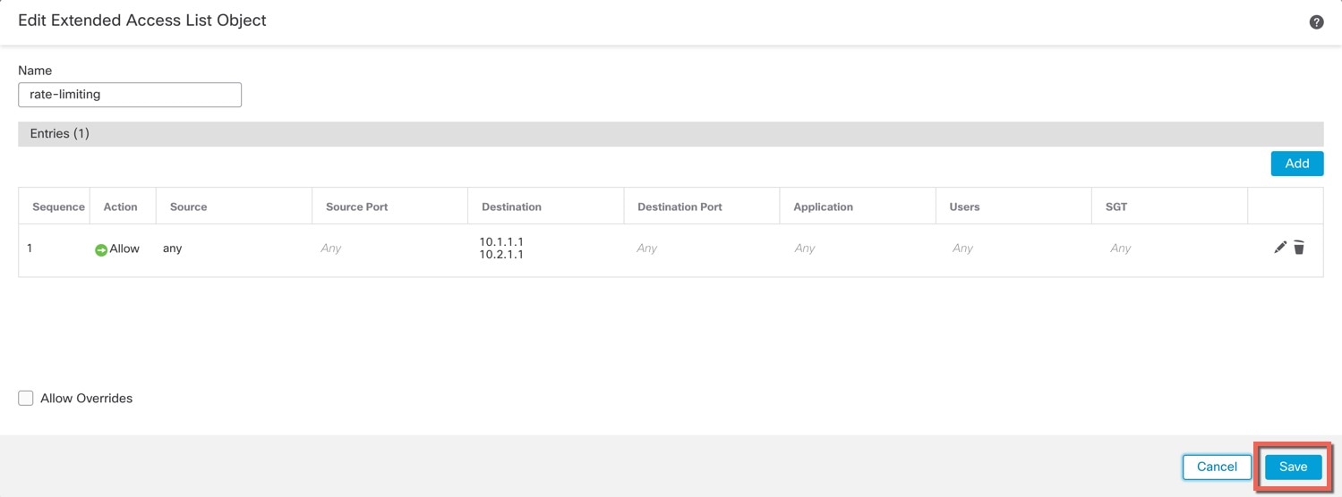
Create an extended access list identifying traffic to the loopback interface IP address(es).

  1. Choose Objects > Object Management > Access List > Extended.

  2. Click Add Extended Access List to create a new ACL.

  3. In the New Extended Access List Object dialog box, enter a name for the ACL (no spaces allowed), and click Add to create a new entry.

    Figure 5. Name ACL and add entry
    Name Entry and Add
  4. Configure the source (any) and destination addresses (loopback IP addresses) on the Network tab.

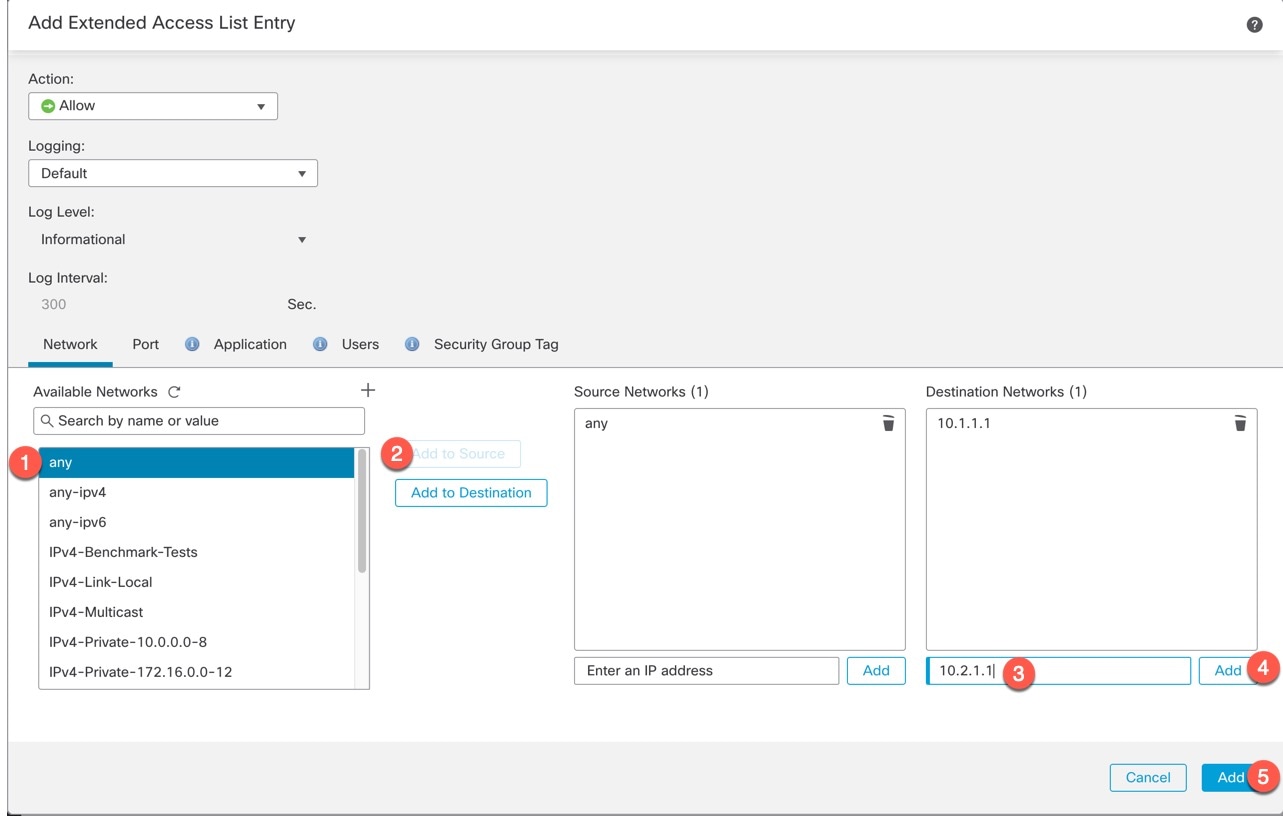
    Figure 6. Source and destination networks
    Source and Destination Networks

    Note


    Keep the default Action as Allow (match) and other settings as-is.

    • Source—Select any from the Available Networks list, and click Add to Source. You can also narrow this access list by specifying the source IP addresses instead of any.

    • Destination—Type an address in the edit box below the Destination Networks list and click Add. Repeat for each loopback interface.

  5. Click Add to add the entry to the ACL.

  6. Click Save to save the ACL.

    Figure 7. Save ACL
    Add ACL Object

Step 2

Choose Policies > Access Control heading > Access Control, and click Edit (edit icon) for the access control policy assigned to your device.

Step 3

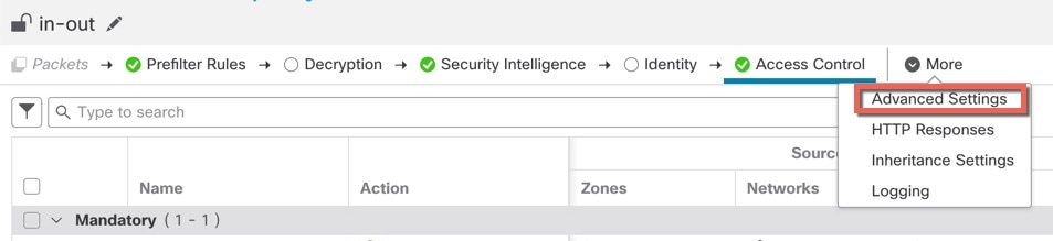
Click Advanced Settings from the More drop-down arrow at the end of the packet flow line.

Figure 8. Advanced settings
Advanced Settings

Step 4

Click Edit (edit icon) in the Threat Defense Service Policy group.

Figure 9. Threat defense service policy
The threat defense service policy outlines the configuration options for rate-limiting traffic to the loopback interface, including rule creation and management.

Step 5

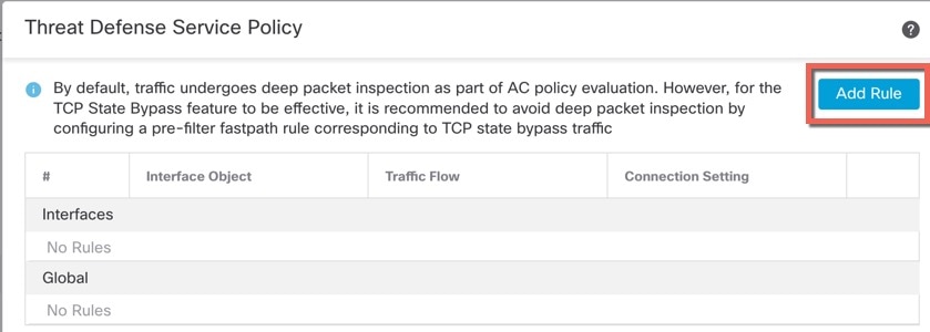
Click Add Rule to create a new rule.

Figure 10. Add rule
Add Rule

The service policy rule wizard opens to step you through the process of configuring the rule.

Step 6

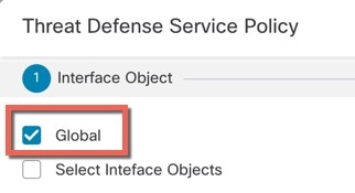
In the Interface Object step, click Global to create a global rule, which applies to all interfaces, then click Next.

Figure 11. Global policy
Global Policy

Step 7

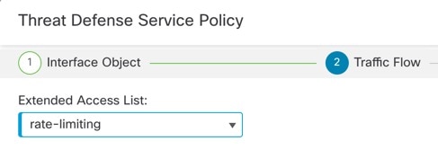
In the Traffic Flow step, select the extended access list object you created in Step 1, and then click Next.

Figure 12. Choose extended access list
Choose Extended Access List

Step 8

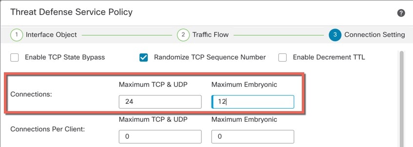
In the Connection Setting step, set the Connections limits.

Figure 13. Set connection limits
Set Connection Limits

Set the Maximum TCP & UDP connections to the expected number of connections for the loopback interface, and the Maximum Embryonic connections to a lower number. For example, you can set it to 5/2, or 10/5, or 1024/512, depending on the expected loopback interface sessions you need.

Setting the embryonic connection limit enables TCP Intercept, which protects the system from a DoS attack perpetrated by flooding an interface with TCP SYN packets.

Step 9

Click Finish to save your changes.

Click OK.

Click Save on the Advanced Settings window.


What to do next

Deploy the changes to the affected devices.

VLAN subinterfaces and 802.1Q trunking

VLAN subinterfaces let you divide a physical, redundant, or EtherChannel interface into multiple logical interfaces that are tagged with different VLAN IDs. An interface with one or more VLAN subinterfaces is automatically configured as an 802.1Q trunk. Because VLANs let you keep traffic separate on a given physical interface, you can increase the number of interfaces available to your network without adding additional physical interfaces or devices.

Guidelines for VLAN subinterfaces

Model support

  • 1010—VLAN subinterfaces are not supported on switch ports or VLAN interfaces.

High availability and clustering

Do not use a subinterface for the failover or state link or for the cluster control link. The exception is for multi-instance mode: you can use a chassis-defined subinterface for these links.

Additional guidelines

  • Preventing untagged packets on the physical interface—If you use subinterfaces, disable the physical interface from passing traffic. The physical interface transmits untagged packets. This behavior also applies to the active physical interface in a redundant interface pair and also to EtherChannel links. For the subinterface to pass traffic, the physical, redundant, or EtherChannel interface must be enabled. If you want to let the physical, redundant, or EtherChannel interface pass untagged packets, you can configure the name as usual.

  • Configure subinterfaces only on non-Management interfaces. Avoid using the dedicated Management interface configured at the CLI or a data interface used for manager access.

  • All subinterfaces on the same parent interface must be either members of bridge groups or routed interfaces; you cannot mix and match.

  • The Firewall Threat Defense does not support the Dynamic Trunking Protocol (DTP), so configure the connected switch port to trunk unconditionally.

  • Assign unique MAC addresses to the subinterfaces that are defined on the Firewall Threat Defense. Subinterfaces use the same burned-in MAC address of the parent interface by default. For example, your service provider might perform access control based on the MAC address. Also, because IPv6 link-local addresses are generated based on the MAC address, assigning unique MAC addresses to subinterfaces allows for unique IPv6 link-local addresses, which can avoid traffic disruption in certain instances on the Firewall Threat Defense.


    Note


    If you manually assign a MAC address, be sure to assign MAC addresses to all subinterfaces on the same physical interface to avoid unexpected behavior and outages.


Maximum number of VLAN subinterfaces by device model

Your device model limits the maximum number of VLAN subinterfaces that you can configure. Note that you can configure subinterfaces on data interfaces only, you cannot configure them on the management interface.

This table explains the limits for each device model.

Model

Maximum VLAN Subinterfaces

Firepower 1010

60

Firepower 1120

512

Firepower 1140, 1150

1024

Firepower 2100

1024

Secure Firewall 3100

1024

Firepower 4100

1024

Firepower 9300

1024

Firewall Threat Defense Virtual

50

ISA 3000

100

Add a subinterface

This task enables you to add subinterfaces to physical, redundant, or port-channel interfaces for network segmentation using VLAN tagging.

Add one or more subinterfaces to a physical, redundant, or port-channel interface.

For the Firepower 4100/9300, you can configure subinterfaces in FXOS for use with container instances; see Add a VLAN Subinterface for Container Instances. These subinterfaces appear in the Firewall Management Center interface list. You can also add subinterfaces in Firewall Management Center, but only on parent interfaces that do not already have subinterfaces defined in FXOS.


Note


The parent physical interface passes untagged packets. You may not want to pass untagged packets, so be sure not to include the parent interface in your security policy.


Procedure


Step 1

Select Devices > Device Management and click Edit (edit icon) for your Firewall Threat Defense device. The Interfaces page is selected by default.

Step 2

Enable the parent interface according to Enable the physical interface and configure Ethernet settings.

Step 3

Click Add Interfaces > Sub Interface.

Step 4

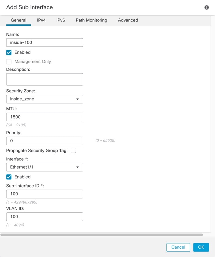
On General, set these parameters:

Figure 14. Add subinterface
Add Subinterface
  1. Interface—Choose the physical, redundant, or port-channel interface to which you want to add the subinterface.

  2. Sub-Interface ID—Enter the subinterface ID as an integer between 1 and 4294967295. The number of subinterfaces allowed depends on your platform. You cannot change the ID after you set it.

  3. VLAN ID—Enter the VLAN ID between 1 and 4094 that will be used to tag the packets on this subinterface.

    This VLAN ID must be unique.

Step 5

Click OK.

Step 6

Click Save.

You can now go to Deploy > Deploy and deploy the policy to assigned devices. The changes are not active until you deploy them.

Step 7

Configure the routed or transparent mode interface parameters. See Configure routed mode interfaces or Bridge group interfaces.


Configure VXLAN Interfaces

This chapter tells how to configure Virtual eXtensible LAN (VXLAN) interfaces. VXLAN interfaces act as Layer 2 virtual networks over Layer 3 physical networks to stretch Layer 2 networks.

VXLAN interfaces

Virtual Extensible Local Area Network (VXLAN) is a network encapsulation protocol that provides flexible placement of multitenant segments throughout the data center. VXLAN offers higher scalability, supporting up to 16 million Layer 2 segments. VXLAN delivers Ethernet Layer 2 network services similar to VLAN and provides greater extensibility and flexibility.

Additional information

For detailed information about VXLAN, see RFC 7348.

encapsulation

The Firewall Threat Defense supports two types of VXLAN encapsulation:

  • VXLAN (all models)—VXLAN uses MAC Address-in-User Datagram Protocol (MAC-in-UDP) encapsulation. The original Layer 2 frame has a VXLAN header added and is then placed in a UDP-IP packet.

  • Geneve (Firewall Threat Defense Virtual only)—Geneve has a flexible inner header that is not limited to the MAC address. Geneve encapsulation is required for transparent routing of packets between an Amazon Web Services (AWS) Gateway Load Balancer and appliances, and for sending extra information.

VXLAN tunnel endpoints

A VXLAN tunnel endpoint (VTEP) devices performs VXLAN encapsulation and decapsulation. Each VTEP has two interface types: one or more virtual interfaces called VXLAN Network Identifier (VNI) interfaces to which you apply your security policy, and a regular interface called the VTEP source interface that tunnels the VNI interfaces between VTEPs. The VTEP source interface is attached to the transport IP network for VTEP-to-VTEP communication.

VTEP network communication

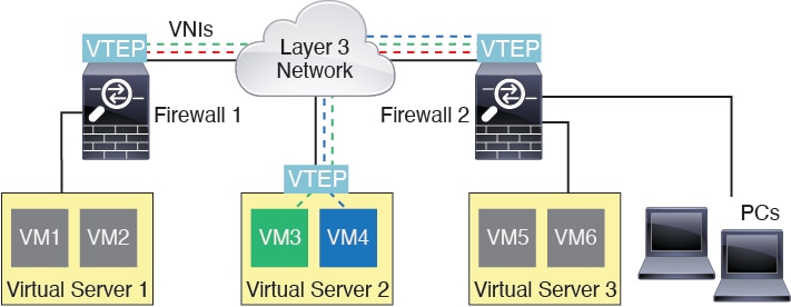
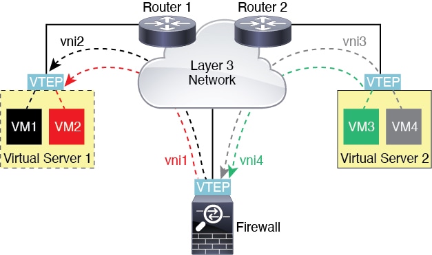
This figure shows two Firewall Threat Defenses and Virtual Server 2 acting as VTEPs across a Layer 3 network, extending the VNI 1, 2, and 3 networks between sites. The Firewall Threat Defenses act as bridges or gateways between VXLAN and non-VXLAN networks.

The diagram illustrates the communication process between VXLAN tunnel endpoints (VTEPs) in a network, highlighting the encapsulation and decapsulation of packets as they traverse the VXLAN overlay.

The underlying IP network between VTEPs is independent of the VXLAN overlay. Encapsulated packets are routed based on the outer IP address header, which has the initiating VTEP as the source IP address and the terminating VTEP as the destination IP address. For VXLAN encapsulation: The destination IP address can be a multicast group when the remote VTEP is not known. With Geneve, the Firewall Threat Defense only supports static peers. The destination port for VXLAN is UDP port 4789 by default (user configurable). The destination port for Geneve is 6081.

VTEP source interface

A VTEP source interface is a regular interface (physical, EtherChannel, or even VLAN) that you plan to associate with all VNI interfaces. You can configure one VTEP source interface per Firewall Threat Defense Virtual.

VTEP source interface characteristics

The VTEP source interface can be devoted wholly to VXLAN traffic, although it is not restricted to that use. You can use the interface to handle regular traffic and apply a security policy to it. However, for VXLAN traffic, you must apply all security policies to the VNI interfaces. The VTEP interface serves as a physical port only.

In transparent firewall mode, the VTEP source interface is not part of a BVI. You must configure an IP address for it, similar to how the management interface is configured.

Because you can only configure one VTEP source interface, you cannot configure both VXLAN and Geneve interfaces on the same device. There is an exception for Firewall Threat Defense Virtual clustering on AWS, where you can have two VTEP source interfaces: a VXLAN interface is used for the cluster control link, and a Geneve interface can be used for the Gateway Load Balancer.

VNI interfaces

A VNI interface is a virtual interface that keeps network traffic separated on a given physical interface by using tagging. VNI interfaces are similar to VLAN interfaces. You can apply your security policy directly to each interface.

VNI interface configuration details

You can add only one VTEP interface. All VNI interfaces are associated with the same VTEP interface. There is an exception for Firewall Threat Defense Virtual clustering on AWS. For AWS clustering, you can have two VTEP source interfaces: a VXLAN interface is used for the cluster control link, and a Geneve interface can be used for the AWS Gateway Load Balancer.

How VXLAN and Geneve packets are processed

Summary

The key components involved in VXLAN and Geneve packet processing are:

  • VTEP source interface: Performs encapsulation and decapsulation of VXLAN and Geneve traffic

  • Inner MAC frame: The original packet payload that gets encapsulated

  • Outer frame: The encapsulated packet with VXLAN or Geneve headers

  • Remote VTEP: The destination endpoint for encapsulated traffic

Workflow

These stages describe how VXLAN and Geneve packet processing work:

  1. Traffic entering and exiting the VTEP source interface is subject to VXLAN processing, specifically encapsulation or decapsulation. Encapsulation processing includes these tasks:
    • The VTEP source interface encapsulates the inner MAC frame with the VXLAN header.
    • The UDP checksum field is set to zero.
    • The Outer frame source IP is set to the VTEP interface IP.
    • The Outer frame destination IP is decided by a remote VTEP IP lookup.
    Decapsulation: the Firewall Threat Defense only decapsulates a VXLAN packet if:
    • It is a UDP packet with the destination port set to 4789 (this value is user configurable).
    • The ingress interface is the VTEP source interface.
    • The ingress interface IP address is the same as the destination IP address.
    • The VXLAN packet format is compliant with the standard.
  2. Traffic entering and exiting the VTEP source interface is subject to Geneve processing, specifically encapsulation or decapsulation. Encapsulation processing includes these tasks:
    • The VTEP source interface encapsulates the inner MAC frame with the Geneve header.
    • The UDP checksum field is set to zero.
    • The Outer frame source IP is set to the VTEP interface IP.
    • The Outer frame destination IP is set the peer IP address that you configured.
    Decapsulation; the Firewall Threat Defense only decapsulates a Geneve packet if:
    • It is a UDP packet with the destination port set to 6081 (this value is user configurable).
    • The ingress interface is the VTEP source interface.
    • The ingress interface IP address is the same as the destination IP address.
    • The Geneve packet format is compliant with the standard.

Peer VTEPs

A peer VTEP is a VXLAN Tunnel Endpoint that enables the Firewall Threat Defense to send packets to devices behind remote VTEPs.

When the Firewall Threat Defense sends a packet to a device behind a peer VTEP, the Firewall Threat Defense needs two important pieces of information:

  • The destination MAC address of the remote device

  • The destination IP address of the peer VTEP

The Firewall Threat Defense maintains a mapping of destination MAC addresses to remote VTEP IP addresses for the VNI interfaces.

VXLAN peer configuration methods

There are two ways in which the Firewall Threat Defense can find this information:

  • A single peer VTEP IP address can be statically configured on the Firewall Threat Defense.

    The Firewall Threat Defense then sends a VXLAN-encapsulated ARP broadcast to the VTEP to learn the end node MAC address.

  • A group of peer VTEP IP addresses can be statically configured on the Firewall Threat Defense.

    The Firewall Threat Defense then sends a VXLAN-encapsulated ARP broadcast to the VTEP to learn the end node MAC addresses.

  • A multicast group can be configured on each VNI interface (or on the VTEP as a whole).

    The Firewall Threat Defense sends a VXLAN-encapsulated ARP broadcast packet within an IP multicast packet through the VTEP source interface. The response to this ARP request enables the Firewall Threat Defense to learn both the remote VTEP IP address along with the destination MAC address of the remote end node.

    This option is not supported with Geneve.

Geneve peer configuration

The Firewall Threat Defense Virtual only supports statically defined peers. You can define the Firewall Threat Defense Virtual peer IP address on the AWS Gateway Load Balancer. Because the Firewall Threat Defense Virtual never initiates traffic to the Gateway Load Balancer, you do not also have to specify the Gateway Load Balancer IP address on the Firewall Threat Defense Virtual. It learns the peer IP address when it receives Geneve traffic. Multicast groups are not supported with Geneve.

VXLAN use cases

This section describes the use cases for implementing VXLAN on the Firewall Threat Defense.

VXLAN bridge or gateway overview

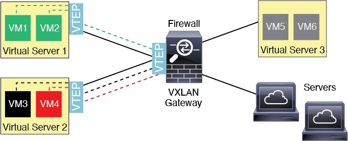
A VTEP acts as a bridge or gateway between end nodes, such as VMs, servers, and PCs, and the VXLAN overlay network.

VXLAN Packet Processing

For incoming frames received with VXLAN encapsulation over the VTEP source interface, the Firewall Threat Defense strips out the VXLAN header and forwards it to a physical interface connected to a non-VXLAN network based on the destination MAC address of the inner Ethernet frame.

The Firewall Threat Defense always processes VXLAN packets rather than forwarding them untouched between two other VTEPs.

VXLAN gateway operation
VXLAN bridge

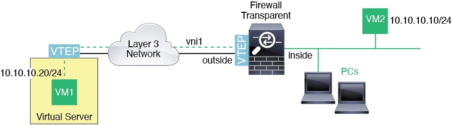
A VXLAN bridge is a network configuration where the Firewall Threat Defense connects a remote VXLAN segment to a local segment.

When you use a bridge group (transparent firewall mode, or optionally routed mode), the Firewall Threat Defense can serve as a VXLAN bridge between a (remote) VXLAN segment and a local segment where both are in the same network. In this case, one member of the bridge group is a regular interface while the other member is a VNI interface.

VXLAN bridge
VXLAN gateway (routed mode)

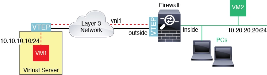
The Firewall Threat Defense functions as a router between VXLAN and non-VXLAN domains, connecting devices on different networks.

VXLAN Gateway Visual Representation

This figure illustrates the VXLAN gateway connectivity.

VXLAN gateway connectivity
Router Between VXLAN Domains

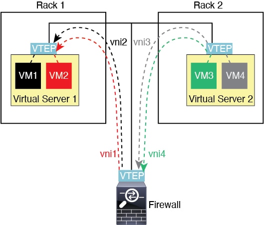
A VXLAN-stretched Layer 2 domain enables a VM to utilize a Firewall Threat Defense as its default gateway regardless of physical proximity.

Routing Process and Packet Flow

The following steps outline the packet flow between VMs across VXLAN domains:

  1. For packets from VM3 to VM1, the destination MAC address is the Firewall Threat Defense MAC address, because the Firewall Threat Defense is the default gateway.

  2. The VTEP source interface on Virtual Server 2 receives packets from VM3, then encapsulates the packets with VNI 3’s VXLAN tag and sends them to the Firewall Threat Defense .

  3. When the Firewall Threat Defense receives the packets, it decapsulates the packets to get the inner frames.

  4. The Firewall Threat Defense uses the inner frames for route lookup, then finds that the destination is on VNI 2. If it does not already have a mapping for VM1, the Firewall Threat Defense sends an encapsulated ARP broadcast on the multicast group IP on VNI 2.

  5. The Firewall Threat Defense encapsulates the packets again with the VXLAN tag for VNI 2 and sends the packets to Virtual Server 1. Before encapsulation, the Firewall Threat Defense changes the inner frame destination MAC address to be the MAC of VM1.

  6. When Virtual Server 1 receives the VXLAN packets, it decapsulates the packets and delivers the inner frames to VM1.


Note


The Firewall Threat Defense must use dynamic VTEP peer discovery because it has multiple VTEP peers in this scenario.


Router Between VXLAN Domains
Geneve Single-Arm Proxy

In a Geneve single-arm proxy deployment, network traffic is routed through a centralized proxy device for inspection and policy enforcement.


Note


This use case is the only currently supported use case for Geneve interfaces.


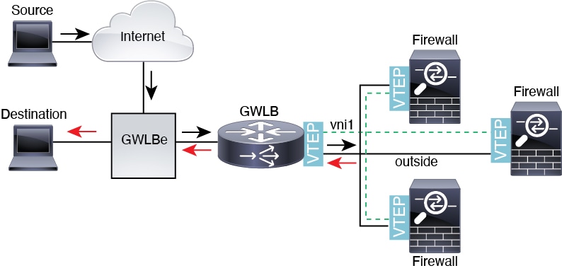
The AWS Gateway Load Balancer combines a transparent network gateway and a load balancer that distributes traffic and scales virtual appliances on demand. The Firewall Threat Defense Virtual supports the Gateway Load Balancer centralized control plane with a distributed data plane (Gateway Load Balancer endpoint). The following figure shows traffic forwarded to the Gateway Load Balancer from the Gateway Load Balancer endpoint. The Gateway Load Balancer balances traffic among multiple Firewall Threat Defense Virtuals, which inspect the traffic before either dropping it or sending it back to the Gateway Load Balancer (U-turn traffic). The Gateway Load Balancer then sends the traffic back to the Gateway Load Balancer endpoint and to the destination.

Figure 15. Geneve Single-Arm Proxy

Requirements and prerequisites for VXLAN interfaces

This reference provides the model requirements and prerequisites for configuring VXLAN interfaces on supported platforms.

Model requirements

  • VXLAN encapsulation is supported on all models.

  • Geneve encapsulation is supported for these models:

    • Firewall Threat Defense Virtual in Amazon Web Services (AWS)

  • Firepower 1010 switch ports and VLAN interfaces are not supported as VTEP interfaces.

Guidelines for VXLAN interfaces

Firewall mode restrictions

Geneve interfaces are only supported in routed firewall mode.

IPv6 support restrictions

The VNI interface supports both IPv4 and IPv6 traffic.

  • The VTEP source interface IP address only supports IPv4.

Clustering restrictions

Clustering does not support VXLAN in Individual Interface mode except for the cluster control link (Firewall Threat Defense Virtual only) Only Spanned EtherChannel mode supports VXLAN.

An exception is made for AWS, which can use an additional Geneve interface for use with the GWLB.

Routing restrictions

Only static routing or Policy Based Routing is supported on the VNI interface; dynamic routing protocols are not supported.

VPN restrictions

You cannot configure the VTEP source interface for VPN or use it as a VTI.

MTU requirements

If the source interface MTU is less than the required minimum, the Firewall Threat Defense automatically raises the MTU to meet encapsulation requirements.

  • VXLAN encapsulation—If the source interface MTU is less than 1554 bytes, then the Firewall Threat Defense automatically raises the MTU to 1554 bytes. In this case, the entire Ethernet datagram is being encapsulated, so the new packet is larger and requires a larger MTU. If the MTU used by other devices is larger, then you should set the source interface MTU to be the network MTU + 54 bytes. For the Firewall Threat Defense Virtual, this MTU requires a restart to enable jumbo frame reservation.

  • Geneve encapsulation—If the source interface MTU is less than 1806 bytes, then the Firewall Threat Defense automatically raises the MTU to 1806 bytes. In this case, the entire Ethernet datagram is being encapsulated, so the new packet is larger and requires a larger MTU. If the MTU used by other devices is larger, then you should set the source interface MTU to be the network MTU + 306 bytes. This MTU requires a restart to enable jumbo frame reservation.

Configure VXLAN or Geneve interfaces

You can configure either VXLAN or Geneve interfaces.

Configure VXLAN interfaces

Configure VXLAN interfaces to enable virtualized network overlay functionality and network segmentation.

VXLAN provides Layer 2 overlay network capabilities over existing Layer 3 infrastructure. You can configure either VXLAN or Geneve interfaces, but not both simultaneously.


Note


You can configure either VXLAN or Geneve (Firewall Threat Defense Virtual only). For Geneve interfaces, see Configure geneve interfaces.


Follow these steps to configure VXLAN interfaces.

Procedure

Step 1

Configure the VTEP source interface.

Step 2

Configure the VNI interface.


Configure the VTEP source interface

This task enables you to set up VXLAN network virtualization by configuring a Network Virtualization Endpoint (NVE) on your firewall device.

You can configure one VTEP source interface per Firewall Threat Defense device. The VTEP is defined as a Network Virtualization Endpoint (NVE). VXLAN is the default encapsulation type.

Procedure

Step 1

If you want to specify a group of peer VTEPs, add a network object with the peer IP addresses. See Create a network object.

Step 2

Choose Devices > Device Management.

Step 3

Click Edit (edit icon) next to the device on which you want to configure VXLAN.

Step 4

(Optional) Specify that the source interface is NVE-only.

This setting is optional for routed mode where this setting restricts traffic to VXLAN and common management traffic only on this interface. This setting is automatically enabled for transparent firewall mode.

  1. Click Interfaces.

  2. Click Edit (edit icon) for the VTEP source interface.

  3. On the General page, check the check box of NVE Only.

Step 5

Click VTEP if it is not already displaying.

Step 6

Check Enable NVE.

Step 7

Click Add VTEP.

  1. For the Encapsulation Type, choose VXLAN.

    For AWS, you can choose between VXLAN and Geneve. Other platforms have VXLAN chosen automatically.

  2. Enter the value for the Encapsulation port within the specified range.

    The default value is 4789.

  3. Select the VTEP Source Interface.

    Select from the list of available physical interfaces present on the device. If the source interface MTU is less than 1554 bytes, then the Firewall Management Center automatically raises the MTU to 1554 bytes.

  4. Select the Neighbor Address. The available options are:

    • None—No neighbor address is specified.

    • Peer VTEP—Specify a peer VTP address.

    • Peer Group—Specify a network object with the peer IP addresses.

    • Default Multicast—Specify a default multicast group for all associated VNI interfaces. If you do not configure the multicast group per VNI interface, then this group is used. If you configure a group at the VNI interface level, then that group overrides this setting.

Step 8

Click OK.

Step 9

Click Save.


What to do next

Configure the routed interface parameters. See Configure Routed Mode Interfaces.

Configure the VNI interface

Add a VNI interface, associate it with the VTEP source interface, and configure basic interface parameters.

Procedure

Step 1

Choose Devices > Device Management.

Step 2

Click Edit (edit icon) next to the device on which you want to configure VXLAN.

Step 3

Click Interfaces.

Step 4

Click Add Interfaces, and then choose VNI Interface.

  1. Enter the interface Name and Description.

  2. From the Security Zone drop-down list, choose a security zone or add a new one by clicking New.

  3. Enter a value for the Priority field within the specified range. By default, 0 is selected.

  4. Enter a value for the Priority field within the specified range. By default, 0 is selected.

  5. Enter a value for the VNI ID between 1 and 10000.

    This ID is only an internal interface identifier.

Step 5

Enter a value for the VNI Segment ID between 1 and 16777215.

The segment ID is used for VXLAN tagging.

Step 6

Enter the Multicast Group IP Address.

If you do not set the multicast group for the VNI interface, the default group from the VTEP source interface configuration is used, if available. If you manually set a VTEP peer IP for the VTEP source interface, you cannot specify a multicast group for the VNI interface.

Step 7

Check NVE Mapped to VTEP Interface.

This option associates this interface with the VTEP source interface.

Step 8

Click OK.

Click Save to save the interface configuration.


What to do next

Configure the routed or transparent interface parameters. See Configure routed and transparent mode interfaces.

Configure geneve interfaces

To configure Geneve interfaces for Firewall Threat Defense Virtual, perform the following steps.


Note


You can configure either VXLAN or Geneve. For information about VXLAN interfaces, see Configure VXLAN interfaces.


  1. Configure the VTEP source interface.

  2. Configure the VNI.

  3. Allow gateway load balancer health checks.

Configure the VTEP source interface

Configure the VTEP source interface to enable network virtualization functionality on the device.

You can configure one VTEP source interface per Firewall Threat Defense Virtual device. The VTEP is defined as a Network Virtualization Endpoint (NVE).

Procedure

Step 1

Choose Devices > Device Management.

Step 2

Click Edit (edit icon) next to the device on which you want to configure Geneve.

Step 3

Click VTEP.

Step 4

Check Enable NVE.

Step 5

Click Add VTEP.

  1. For the Encapsulation Type, choose Geneve.

  2. Enter the value for the Encapsulation port within the specified range.

    We do not recommend changing the Geneve port; AWS requires a port of 6081.

  3. Select the VTEP Source Interface.

    You can select from the list of available physical interfaces present on the device. If the source interface MTU is less than 1806 bytes, then the Firewall Management Center automatically raises the MTU to 1806 bytes.

  4. Click OK.

Step 6

Click Save.

Step 7

Configure the routed interface parameters. See Configure Routed Mode Interfaces.


Configure the VNI

This task enables you to add a VNI interface and configure its basic parameters for Geneve functionality on your device.

Add a VNI, associate it with (VTEP) source interface, and configure basic interface parameters.

Procedure

Step 1

Choose Devices > Device Management.

Step 2

Click Edit (edit icon) next to the device on which you want to configure Geneve.

Step 3

Click Interfaces.

Step 4

Click Add Interfaces, and then choose VNI Interface.

  1. In the Name and Description fields, provide relevant information.

  2. In the VNI ID field, enter a value between 1 and 10000.

    Note


    This ID is only an internal interface identifier.

Step 5

Check the Enable Proxy check box.

Note


When the AWS proxy is enabled on the VNI interface of your device, configuring NAT is not allowed.

This option enables single-arm proxy, and allows traffic to exit the same interface it entered (U-turn traffic). If you edit the interface later , you cannot disable single-arm proxy. To disable single-arm proxy, delete the existing interface and create a new VNI interface.

This option is only available for a Geneve VTEP.

Step 6

Select NVE Mapped to VTEP Interface.

This option associates this interface with the VTEP source interface.

Step 7

Click OK.

Step 8

Click Save.


What to do next

Configure the routed interface parameters. See Configure Routed Mode Interfaces.

Allow gateway load balancer health checks

The AWS gateway load balancer (GWLB) requires appliances to answer a health check properly. The GWLB will only send traffic to appliances that are considered healthy.

Configure one of these methods to enable proper health check responses.

Procedure


Step 1

Configure SSH. See Configure Secure Shell

Allow SSH from the GWLB IP address. The GWLB will attempt to establish a connection to the Firewall Threat Defense Virtual, and the Firewall Threat Defense Virtual's prompt to log in is taken as proof of health. An SSH login attempt will time out after 1 minute. You will need to configure a longer health check interval on the GWLB to accommodate this timeout.

Step 2

Configure HTTP(S) Redirection Using Static Interface NAT with Port Translation.

You can configure the Firewall Threat Defense Virtual to redirect health checks to a metadata HTTP(S) server. For HTTP(S) health checks, the HTTP(S) server must reply to the GWLB with a status code in the range 200 to 399. Because the Firewall Threat Defense Virtual has limits on the number of simultaneous management connections, you may choose to offload the health check to an external server.

Static interface NAT with port translation lets you redirect a connection to a port (such as port 80) to a different IP address. For example, translate an HTTP packet from the GWLB with a destination of the Firewall Threat Defense Virtual outside interface so that it appears to be from the Firewall Threat Defense Virtual outside interface with a destination of the HTTP server. The Firewall Threat Defense Virtual then forwards the packet to the mapped destination address. The HTTP server responds to the Firewall Threat Defense Virtual outside interface, and then the Firewall Threat Defense Virtual forwards the response back to the GWLB. You need an access rule that allows traffic from the GWLB to the HTTP server.

  1. Permit HTTP(S) traffic on the outside interface from the GWLB network in an access rule. See Access Control Rules.

  2. For HTTP(S), translate the source GWLB IP address to the Firewall Threat Defense Virtual outside interface IP address; then translate the destination of the outside interface IP address to the HTTP(S) server IP address. See Configure static manual NAT.


Configure routed and transparent mode interfaces

This section includes tasks to complete the regular interface configuration for all models in routed or transparent firewall mode.

Routed and transparent mode interfaces

Firewall mode interfaces subject traffic to firewall functions such as maintaining flows, tracking flow states at both IP and TCP layers, IP defragmentation, and TCP normalization. You can also optionally configure IPS functions for this traffic according to your security policy.

Interface types by firewall mode

The types of firewall interfaces you can configure depends on the firewall mode set for the device: routed or transparent mode. See Transparent or Routed Firewall Mode for more information.

  • Routed mode interfaces (routed firewall mode only)—Each interface that you want to route between is on a different subnet.

  • Bridge group interfaces (routed and transparent firewall mode)—You can group together multiple interfaces on a network, and the Firewall Threat Defense device uses bridging techniques to pass traffic between the interfaces. Each bridge group includes a Bridge Virtual Interface (BVI) to which you assign an IP address on the network. In routed mode, the Firewall Threat Defense device routes between BVIs and regular routed interfaces. In transparent mode, each bridge group is separate and cannot communicate with each other.

Dual IP stack (IPv4 and IPv6)

A dual IP stack is a network configuration that enables both IPv6 and IPv4 addresses on the same interface on Firewall Threat Defense device. Make sure you configure a default route for both IPv4 and IPv6.

31-bit subnet masks

A 31-bit subnet mask includes only two addresses for point-to-point connections.

31-bit subnet mask implementation

For routed interfaces, you can configure an IP address on a 31-bit subnet for point-to-point connections. Normally, the first and last address in a 2-address subnet is reserved for the network and broadcast, so a 2-address subnet is not usable. However, if you have a point-to-point connection and do not need network or broadcast addresses, a 31-bit subnet is a useful way to preserve addresses in IPv4.

31-bit subnet mask use cases

The failover link between two Firewall Threat Defenses only requires two addresses. Any packet that is transmitted by one end of the link is always received by the other, and broadcasting is unnecessary. You can also have a directly-connected management station running SNMP or Syslog.

Note: 31-bit subnet and clustering compatibility

You can use a 31-bit subnet mask for cluster interfaces, excluding the management interface and the cluster control link.

31-bit subnet and failover

A Firewall Threat Defense using a 31-bit subnet for its interface IP address can't configure a standby IP address due to insufficient addresses.

Interface monitoring limitations

When using a 31-bit subnet for the Firewall Threat Defense interface IP address, you cannot configure a standby IP address for the interface because there are not enough addresses. Normally, an interface for failover should have a standby IP address so the active unit can perform interface tests to ensure standby interface health. Without a standby IP address, the Firewall Threat Defense cannot perform any network tests; only the link state can be tracked.

For the failover and optional separate state link, which are point-to-point connections, you can also use a 31-bit subnet.

31-bit subnet and management

If you have a directly-connected management station, you can use a point-to-point connection for SSH or HTTP on the Firewall Threat Defense, or for SNMP or Syslog on the management station.

Recommendation: 31-bit subnet unsupported features

The 31-bit subnet does not support certain network features that require multiple host addresses.

  • BVI interfaces for bridge groups—The bridge group requires at least 3 host addresses: the BVI, and two hosts connected to two bridge group member interfaces. you must use a /29 subnet or smaller.

  • Multicast Routing

Guidelines and limitations for routed and transparent mode interfaces

Context mode

  • PPPoE is not supported in multiple context mode.

  • For multiple context mode in transparent mode, each context must use different interfaces; you cannot share an interface across contexts.

  • For multiple context mode in transparent mode, each context typically uses a different subnet. You can use overlapping subnets, but your network topology requires router and NAT configuration to make it possible from a routing standpoint.

High availability, Clustering, and Multi-Instance

Do not configure failover links with the procedures in this chapter. See the High availability chapter for more information.

  • For cluster interfaces, see the clustering chapter for requirements.

  • For multi-instance mode, shared interfaces are not supported for bridge group member interfaces (in transparent mode or routed mode).

  • When you use High availability, you must set the IP address and standby address for data interfaces manually; DHCP and PPPoE are not supported. Set the standby IP addresses on the Devices > Device Management > High Availability tab in the Monitored Interfaces area. See the High availability chapter for more information.

IPv6

IPv6 is supported on all interfaces.

  • You can only configure IPv6 addresses manually in transparent mode.

  • The Firewall Threat Defense device does not support IPv6 anycast addresses.

Model guidelines

For the Firewall Threat Defense Virtual on VMware with bridged ixgbevf interfaces, bridge groups are not supported.

  • For the Firepower 2100 series, bridge groups are not supported in routed mode.

VLAN IDs for the ASASM

  • If you add an interface for a VLAN that is not yet assigned to the ASA by the switch, the interface will be in the down state. When you assign the VLAN to the ASA, the interface changes to an up state. See the show interface command for more information about interface states.

Transparent mode and bridge group guidelines

  • You can create up to 250 bridge groups, with 64 interfaces per bridge group.

  • Each directly-connected network must be on the same subnet.

  • The Firewall Threat Defense device does not support traffic on secondary networks; only traffic on the same network as the BVI IP address is supported.

  • An IP address for the BVI is required for each bridge group for to-the-device and from-the-device management traffic, as well as for data traffic to pass through the Firewall Threat Defense device. For IPv4 traffic, specify an IPv4 address. For IPv6 traffic, specify an IPv6 address.

  • You can only configure IPv6 addresses manually.

  • The BVI IP address must be on the same subnet as the connected network. You cannot set the subnet to a host subnet (255.255.255.255).

  • Management interfaces are not supported as bridge group members.

  • For multi-instance mode, shared interfaces are not supported for bridge group member interfaces (in transparent mode or routed mode).

  • For the Firewall Threat Defense Virtual on VMware with bridged ixgbevf interfaces, transparent mode is not supported, and bridge groups are not supported in routed mode.

  • For the Firepower 2100 series, bridge groups are not supported in routed mode.

  • For the / 1010/ , you cannot mix logical VLAN interfaces and physical firewall interfaces in the same bridge group.

  • For the Firepower 4100/9300, data-sharing interfaces are not supported as bridge group members.

  • In transparent mode, you must use at least 1 bridge group; data interfaces must belong to a bridge group.

  • In transparent mode, do not specify the BVI IP address as the default gateway for connected devices; devices need to specify the router on the other side of the Firewall Threat Defense as the default gateway.

  • In transparent mode, the default route, which is required to provide a return path for management traffic, is only applied to management traffic from one bridge group network. This is because the default route specifies an interface in the bridge group as well as the router IP address on the bridge group network, and you can only define one default route. If you have management traffic from more than one bridge group network, you need to specify a regular static route that identifies the network from which you expect management traffic.

  • In transparent mode, PPPoE is not supported for the Diagnostic interface.

  • Transparent mode is not supported on threat defense virtual instances deployed on Amazon Web Services, Microsoft Azure, Google Cloud Platform, and Oracle Cloud Infrastructure.

  • In routed mode, to route between bridge groups and other routed interfaces, you must name the BVI.

  • In routed mode, Firewall Threat Defense-defined EtherChannel interfaces are not supported as bridge group members. EtherChannels on the Firepower 4100/9300 can be bridge group members.

  • Bidirectional Forwarding Detection (BFD) echo packets are not allowed through the Firewall Threat Defense when using bridge group members. If there are two neighbors on either side of the Firewall Threat Defense running BFD, then the Firewall Threat Defense will drop BFD echo packets because they have the same source and destination IP address and appear to be part of a LAND attack.

Additional guidelines and requirements

The Firewall Threat Defense supports only one 802.1Q header in a packet and does not support multiple headers (known as Q-in-Q support) for firewall interfaces.Note: For inline sets and passive interfaces, the FTD supports Q-in-Q up to two 802.1Q headers in a packet, with the exception of the Firepower 4100/9300, which only supports one 802.1Q header.

  • Interface problems, such as frequent up/down status changes, can prevent the floating connection timer from applying correctly to the connections going through the interface. If you have problems with an interface's status, consider clearing all connections after the status becomes stable to clear invalid connections.

Configure routed mode interfaces

Before you begin

This procedure describes how to set the name, security zone, and IPv4 address.


Note


Not all fields are supported for all interface types.


Procedure


Step 1

Select Devices > Device Management and click Edit (edit icon) for your Firewall Threat Defense device. The Interfaces page is selected by default.

Step 2

Click Edit (edit icon) for the interface you want to edit.

Step 3

In the Name field, enter a name up to 48 characters in length.

You cannot start the name with the phrase "cluster". It is reserved for internal use.

Step 4

Enable the interface by checking the Enabled check box.

  1. (Optional) Set this interface to Management Only to limit traffic to management traffic; through-the-box traffic is not allowed.

  2. (Optional) Add a description in the Description field.

    The description can be up to 200 characters on a single line, without carriage returns.

  3. In the Mode drop-down list, choose None .

    Regular firewall interfaces have the mode set to None. The other modes are for IPS-only interface types.

  4. From the Security Zone drop-down list, choose a security zone or add a new one by clicking New .

    The routed interface is a Routed-type interface, and can only belong to Routed-type zones.

  5. See Configure the MTU for information about the MTU .

  6. In the Priority field, enter a number ranging from 0–65535.

    This value is used in the policy based routing configuration. The priority is used to determine how you want to route the traffic across multiple egress interfaces. For more information, see Configure policy-based routing policy.

Step 5

Click the IPv4 tab. To set the IP address, use one of the following options from the IP Type drop-down list.

High Availability, clustering interfaces only support static IP address configuration; DHCP and PPPoE are not supported.

  • Use Static IP —Enter the IP address and subnet mask. For point-to-point connections, you can specify a 31-bit subnet mask (255.255.255.254 or /31). In this case, no IP addresses are reserved for the network or broadcast addresses. You cannot set the standby IP address in this case. For High Availability, you can only use a static IP address. Set the standby IP address on the Devices > Device Management page, click High Availability in the Monitored Interfaces area. If you do not set the standby IP address, the active unit cannot monitor the standby interface using network tests; it can only track the link state.

  • Use DHCP —Configure the following optional parameters:

    • Obtain default route using DHCP —Obtains the default route from the DHCP server.

    • DHCP route metric —Assigns an administrative distance to the learned route, between 1 and 255. The default administrative distance for the learned routes is 1.

  • Use PPPoE —If the interface is connected to a DSL, cable modem, or other connection to your ISP, and your ISP uses PPPoE to provide your IP address, configure the following parameters:

    • VPDN Group Name —Specify a group name of your choice to represent this connection.

    • PPPoE User Name —Specify the username provided by your ISP.

    • PPPoE Password/Confirm Password —Specify and confirm the password provided by your ISP.

    • PPP Authentication —Choose PAP , CHAP , or MSCHAP .

      PAP passes a cleartext username and password during authentication and is not secure. With CHAP, the client returns the encrypted [challenge plus password], with a cleartext username in response to the server challenge. CHAP is more secure than PAP, but it does not encrypt data. MSCHAP is similar to CHAP but is more secure because the server stores and compares only encrypted passwords rather than cleartext passwords as in CHAP. MSCHAP also generates a key for data encryption by MPPE.

    • PPPoE route metric —Assign an administrative distance to the learned route. Valid values are from 1 to 255. By default, the administrative distance for the learned routes is 1.

    • Enable Route Settings —To manually configure the PPPoE IP address, check this box and then enter the IP Address .

      If you select the Enable Route Settings check box and leave the IP Address blank, the ip address pppoe setroute command is applied as shown in this example:

      interface GigabitEthernet0/2
      nameif inside2_pppoe
      cts manual
        propagate sgt preserve-untag
        policy static sgt disabled trusted
      security-level 0
      pppoe client vpdn group test
      pppoe client route distance 10
      ip address pppoe setroute
    • Store Username and Password in Flash —Stores the username and password in flash memory.

      The Firewall Threat Defense device stores the username and password in a special location of NVRAM.

Step 6

(Optional) Configure these fields, if you require them.

  1. (Optional) See Configure IPv6 addressing to configure IPv6 addressing on the IPv6 tab.

  2. (Optional) See Configure the MAC address to manually configure the MAC address on the Advanced tab.

  3. Enable Firewall Management Center manager access on a data interface on the Manager Access page.

    You can enable manager access from a data interface when you first setup the Firewall Threat Defense . If you want to enable or disable manager access after you added the Firewall Threat Defense to the Firewall Management Center , see:

    If you want to change the manager access interface from one data interface to another data interface, you must disable manager access on the original data interface, but do not disable the interface itself yet; the original data interface must be used to perform the deployment. If you want to use the same IP address on the new manager access interface, you can delete or change the IP configuration on the original interface; this change should not affect the deployment. If you use a different IP address for the new interface, then also change the device IP address shown in the Firewall Management Center ; see Update the Hostname or IP Address in the Firewall Management Center . Be sure to also update related configuration to use the new interface such as static routes, DDNS, and DNS settings.

    Manager access from a data interface has the following limitations:

    • You can only enable manager access on one physical, data interface. You cannot use a subinterface or EtherChannel, nor can you create a subinterface on the manager access interface.

    • This interface cannot be management-only.

    • Routed firewall mode only, using a routed interface.

    • PPPoE is not supported. If your ISP requires PPPoE, you will have to put a router with PPPoE support between the Firewall Threat Defense and the WAN modem.

    • The interface must be in the global VRF only.

    • SSH is not enabled by default for data interfaces, so you will have to enable SSH later using the Firewall Management Center. Because the Management interface gateway will be changed to be the data interfaces, you also cannot SSH to the Management interface from a remote network unless you add a static route for the Management interface using the configure network static-routes command. For Firewall Threat Defense Virtual on Amazon Web Services, a console port is not available, so you should maintain your SSH access to the Management interface: add a static route for Management before you continue with your configuration. Alternatively, be sure to finish all CLI configuration (including the configure manager add command) before you configure the data interface for manager access and you are disconnected.

    • You cannot use separate management and event-only interfaces.

    • Clustering is not supported. You must use the Management interface in this case.

    • High availability is not supported. You must use the Management interface in this case.

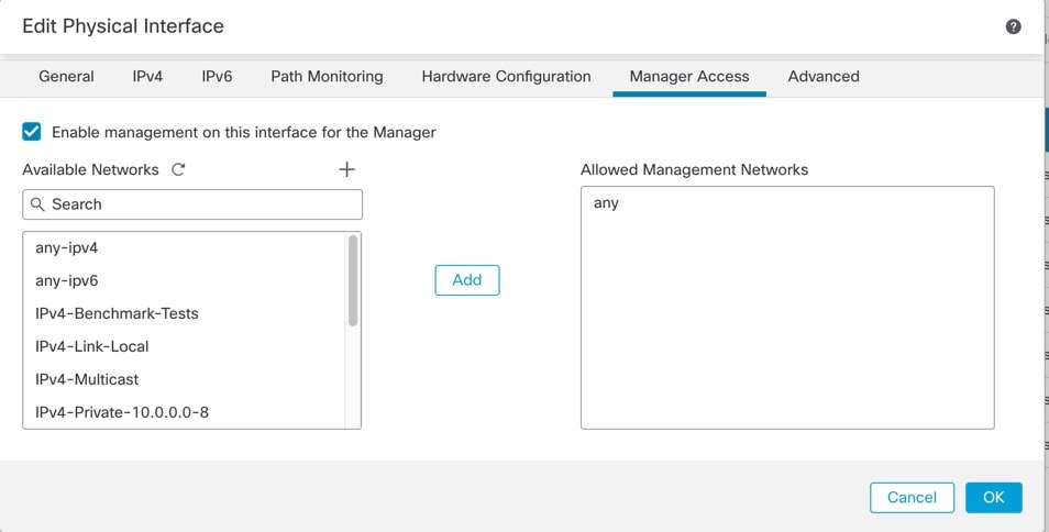
    Figure 16. Manager Access
    Manager Access
    • Check Enable management on this interface for the manager to use this data interface for management instead of the dedicated Management interface.

    • (Optional) In the Allowed Management Networks box, add the networks from which you want to allow manager access. By default, any networks are allowed.

Step 7

(Optional) Set the duplex and speed by clicking Hardware Configuration > Speed.

  • Duplex—Choose Full or Half. SFP interfaces only support Full duplex.

  • Speed—Choose a speed (varies depending on the model).For SFPs, choose Detect SFP to detect the speed of the installed SFP module and use the appropriate speed. Duplex is always full, autonegotiation is enabled, and FEC is set to auto. For dual-speed transceivers, the lower speed is used. This option is useful if you later change the network module to a different model, and want the speed to update automatically. Some switches and transceivers don't support autonegotiation, especially for higher speed interfaces. In this case, set the interface on the Firewall Threat Defense to a manual speed and also disable Auto-negotiation so the link can come up.

    Note

     
    You cannot modify the speed of a high availability or a cluster control link interface.
  • Auto-negotiation—Set the interface to negotiate the link status and flow control.

    Except for the 1100 and 2100, autonegotiation is set separately from the speed. Some switches don't support autonegotiation, especially for higher speed interfaces. In this case, set the interface on the Firewall Threat Defense to a manual speed and also disable Auto-negotiation so the link can come up.

  • Forward Error Correction Mode—For 25Gbps and higher interfaces, enable Forward Error Correction (FEC).

    For an EtherChannel member interface, you must configure FEC before you add it to the EtherChannel. If you remove the interface from the EtherChannel, after rebooting, you may need to reconfigure the FEC for the interface.

    Some switches don't support auto mode for FEC, especially for larger interfaces. Be sure to manually configure the setting, depending on the switch support. We don't recommend disabling FEC; if you do so, the EtherChannel may not come up properly.

    The setting chosen when you use auto depends on the transceiver type and whether the interface is fixed (built-in) or on a network module.

    Table 1. Default FEC for Auto Setting

    Transceiver Type

    Fixed Port Default FEC (Ethernet 1/9 through 1/16)

    Network Module Default FEC

    25G-SR

    Clause 108 RS-FEC

    Clause 108 RS-FEC

    25G-LR

    Clause 108 RS-FEC

    Clause 108 RS-FEC

    10/25G-CSR

    Clause 108 RS-FEC

    Clause 74 FC-FEC

    25G-AOCxM

    Clause 74 FC-FEC

    Clause 74 FC-FEC

    25G-CU2.5/3M

    Auto-Negotiate

    Auto-Negotiate

    25G-CU4/5M

    Auto-Negotiate

    Auto-Negotiate

Note


From Version 7.4.2, Firewall Threat Defense supports the SFP 10G_25G_CSR_S module. To avoid link-down issues after a reboot, Forward Error Correction (FEC) must be enabled on these interfaces.

Step 8

Click OK .

Step 9

Click Save.

You can now go to Deploy > Deploy and deploy the policy to assigned devices. The changes are not active until you deploy them.


Bridge group interfaces

A bridge group is a group of interfaces that the Secure Firewall Threat Defense device bridges instead of routes.

Bridge group support

Bridge groups are supported in both transparent and routed firewall mode.

For more information about bridge groups, see Bridge groups.

To configure bridge groups and associated interfaces, perform these steps.

Configure general bridge group member interface parameters

This task configures the name and security zone for each bridge group member interface to enable bridge group functionality.

The same bridge group can include different types of interfaces: physical interfaces, VLAN subinterfaces, Firepower 1010 VLAN interfaces, EtherChannels, and redundant interfaces. The Management interface is not supported. In routed mode, EtherChannels are not supported. For the Firepower 4100/9300, data-sharing type interfaces are not supported.

Before you begin

Follow these steps to configure general bridge group member interface parameters:

Procedure

Step 1

Select Devices > Device Management and click Edit (edit icon) for your Firewall Threat Defense device. The Interfaces page is selected by default.

Step 2

Click Edit (edit icon) for the interface you want to edit.

Step 3

Configure these fields:

  1. In the Name field, enter a name up to 48 characters in length.

    You cannot start the name with the phrase "cluster". It is reserved for internal use.

  2. Enable the interface by checking the Enabled check box.

  3. (Optional) Set this interface to Management Only to limit traffic to management traffic; through-the-box traffic is not allowed.

  4. (Optional) Add a description in the Description field.

    The description can be up to 200 characters on a single line, without carriage returns.

  5. In the Mode drop-down list, choose None.

    Regular firewall interfaces have the mode set to None. The other modes are for IPS-only interface types. After you assign this interface to a bridge group, the mode will show as Switched.

  6. From the Security Zone drop-down list, choose a security zone or add a new one by clicking New.

    The bridge group member interface is a Switched-type interface, and can only belong to Switched-type zones. Do not configure any IP address settings for this interface. You will set the IP address for the Bridge Virtual Interface (BVI) only. Note that the BVI does not belong to a zone, and you cannot apply access control policies to the BVI.

Step 4

Refer to Configure the MTU for information about MTU.

Step 5

(Optional) Set the duplex and speed by clicking Hardware Configuration > Speed .

  • Duplex —Choose Full or Half . SFP interfaces only support Full duplex.

  • Speed —Choose a speed (varies depending on the model). For SFPs, choose Detect SFP to detect the speed of the installed SFP module and use the appropriate speed. Duplex is always full, autonegotiation is enabled, and FEC is set to auto. For dual-speed transceivers, the lower speed is used. This option is useful if you later change the network module to a different model, and want the speed to update automatically. Some switches and transceivers don't support autonegotiation, especially for higher speed interfaces. In this case, set the interface on the Firewall Threat Defense to a manual speed and also disable Auto-negotiation so the link can come up.

    Note

     
    You cannot modify the speed of a high availability or a cluster control link interface.
  • Auto-negotiation —Set the interface to negotiate the link status and flow control.

    Except for the 1100 and 2100 , autonegotiation is set separately from the speed. Some switches don't support autonegotiation, especially for higher speed interfaces. In this case, set the interface on the Firewall Threat Defense to a manual speed and also disable Auto-negotiation so the link can come up.

  • Forward Error Correction Mode —For 25Gbps and higher interfaces, enable Forward Error Correction (FEC).

    For an EtherChannel member interface, configure FEC before adding it to the EtherChannel. If you remove the interface from EtherChannel and then reboot, reconfigure the FEC for the interface.

    Some switches don't support auto mode for FEC, especially for larger interfaces. Be sure to manually configure the setting, depending on the switch support. We don't recommend disabling FEC because the EtherChannel may not function correctly.

    The setting chosen when you use auto depends on the transceiver type and whether the interface is fixed (built-in) or on a network module.

    Table 2. Default FEC for Auto Setting

    Transceiver Type

    Fixed Port Default FEC (Ethernet 1/9 through 1/16)

    Network Module Default FEC

    25G-SR

    Clause 108 RS-FEC

    Clause 108 RS-FEC

    25G-LR

    Clause 108 RS-FEC

    Clause 108 RS-FEC

    10/25G-CSR

    Clause 108 RS-FEC

    Clause 74 FC-FEC

    25G-AOC x M

    Clause 74 FC-FEC

    Clause 74 FC-FEC

    25G-CU2.5/3M

    Auto-Negotiate

    Auto-Negotiate

    25G-CU4/5M

    Auto-Negotiate

    Auto-Negotiate

Note


From Version 7.4.2, Firewall Threat Defense supports the SFP 10G_25G_CSR_S module. To avoid link-down issues after a reboot, Forward Error Correction (FEC) must be enabled on these interfaces.

Step 6

(Optional) Refer to Configure IPv6 addressing to configure IPv6 addressing on the IPv6 tab.

Step 7

(Optional) Refer to Configure the MAC address to manually configure the MAC address on the Advanced tab.

Step 8

Click OK.

Step 9

Click Save.

You can now go to Deploy > Deploy and deploy the policy to assigned devices. The changes are not active until you deploy them.


Configure the bridge virtual interface (BVI)

Configure a Bridge Virtual Interface (BVI) to provide IP addressing for each bridge group, which enables traffic routing and management functionality for the bridge group members.

Each bridge group requires a BVI for which you configure an IP address. The Firewall Threat Defense uses this IP address as the source address for packets originating from the bridge group. The BVI IP address must be on the same subnet as the connected network. For IPv4 traffic, the BVI IP address is required to pass any traffic. For IPv6 traffic, you must, at a minimum, configure the link-local addresses to pass traffic, but a global management address is recommended for full functionality, including remote management and other management operations.

For routed mode, if you provide a name for the BVI, then the BVI participates in routing. Without a name, the bridge group remains isolated as in transparent firewall mode.


Note


For a separate Diagnostic interface, a non-configurable bridge group (ID 301) is automatically added to your configuration. This bridge group is not included in the bridge group limit.


Before you begin

You cannot add the BVI to a security zone; therefore, you cannot apply Access Control policies to the BVI. You must apply your policy to the bridge group member interfaces based on their zones.

Follow these steps to configure the Bridge Virtual Interface (BVI):

Procedure

Step 1

Select Devices > Device Management and click Edit (edit icon) for your Firewall Threat Defense device. The Interfaces page is selected by default.

Step 2

Choose Add Interfaces > Bridge Group Interface.

  1. (Routed Mode) In the Name field, enter a name up to 48 characters in length.

    You must name the BVI if you want to route traffic outside the bridge group members, for example, to the outside interface or to members of other bridge groups. The name is not case-sensitive.

Step 3

In the Bridge Group ID field, enter the bridge group ID between 1 and 250.

Step 4

In the Description field, enter a description for this bridge group.

Step 5

On the Interfaces tab, click an interface and then click Add to move it to the Selected Interfaces area. Repeat for all interfaces that you want to make members of the bridge group.

Step 6

Click the IPv4 tab.

  1. (Routed Mode) To set the IP address, use one of the following options from the IP Type drop-down list.

    High Availability and clustering interfaces only support static IP address configuration; DHCP is not supported.

    • Use Static IP—Enter the IP address and subnet mask. For High Availability, you can only use a static IP address. Set the standby IP address on the Devices > Device Management, click the High Availability tab in the Monitored Interfaces area. If you do not set the standby IP address, the active unit cannot monitor the standby interface using network tests; it can only track the link state.

    • Use DHCP—Configure the following optional parameters:

      • Obtain default route using DHCP—Obtains the default route from the DHCP server.

      • DHCP route metric—Assigns an administrative distance to the learned route, between 1 and 255. The default administrative distance for the learned routes is 1.

  2. (Transparent Mode) In the IP Address field, enter the IPv4 address and subnet mask.

    Do not assign a host address (/32 or 255.255.255.255) to the BVI. Also, do not use other subnets that contain fewer than 3 host addresses (one each for the upstream router, downstream router, and transparent firewall) such as a /30 subnet (255.255.255.252). The Firewall Threat Defense device drops all ARP packets to or from the first and last addresses in a subnet. For example, if you use a /30 subnet and assign a reserved address from that subnet to the upstream router, then the Firewall Threat Defense device drops the ARP request from the downstream router to the upstream router.

    For High Availability, set the standby IP address on the Devices > Device Management page, click the High Availability tab in the Monitored Interfaces area. If you do not set the standby IP address, the active unit cannot monitor the standby interface using network tests; it can only track the link state.

Step 7

(Optional) Refer to Configure IPv6 addressing to configure IPv6 addressing.

Step 8

(Optional) Refer to Add a static ARP entry and Add a static MAC address and disable MAC learning for a bridge group (for transparent mode only) to configure the ARP and MAC settings.

Step 9

Click OK.

Click Save.


What to do next

Go to Deploy > Deploy and deploy the policy to assigned devices. The changes are not active until you deploy them.

Configure IPv6 addressing

This section describes how to configure IPv6 addressing in routed and transparent mode.

About IPv6

This section includes information about IPv6.

IPv6 addressing

IPv6 addressing provides 128 bits of network addressing, which provides more than enough globally unique IP addresses. It supports both public global addresses and private link-local addresses, and

IPv6 address types

You can configure two types of unicast addresses for IPv6:

  • Global—The global address is a public address that you can use on the public network. For a bridge group, this address needs to be configured for the BVI, and not per member interface. You can also configure a global IPv6 address for the management interface in transparent mode.

  • Link-local—The link-local address is a private address that you can only use on the directly-connected network. Routers do not forward packets using link-local addresses; they are only for communication on a particular physical network segment. They can be used for address configuration or for the Neighbor Discovery functions such as address resolution. In a bridge group, only member interfaces have link-local addresses; the BVI does not have a link-local address.

At a minimum, you need to configure a link-local address for IPv6 to operate. If you configure a global address, a link-local address is automatically configured on the interface, so you do not also need to specifically configure a link-local address. For bridge group member interfaces, when you configure the global address on the BVI, the Firewall Threat Defense device automatically generates link-local addresses for member interfaces. If you do not configure a global address, then you need to configure the link-local address, either automatically or manually.

Modified EUI-64 interface IDs

RFC 3513: Internet Protocol Version 6 (IPv6) Addressing Architecture requires that the interface identifier portion of all unicast IPv6 addresses, except those that start with binary value 000, be 64 bits long and be constructed in Modified EUI-64 format. The Firewall Threat Defense device can enforce this requirement for hosts attached to the local link.

Address verification process

When this feature is enabled on an interface, the source addresses of IPv6 packets received on that interface are verified against the source MAC addresses to ensure that the interface identifiers use the Modified EUI-64 format. If the IPv6 packets do not use the Modified EUI-64 format for the interface identifier, the packets are dropped and this system log message is generated:

325003: EUI-64 source address check failed.

The address format verification is only performed when a flow is created. Packets from an existing flow are not checked. Additionally, the address verification can only be performed for hosts on the local link.

Configure a global IPv6 address

Before you begin

For IPv6 neighbor discovery for bridge groups, you must explicitly allow Neighbor Solicitation (ICMPv6 type 135) and Neighbor Advertisement (ICMPv6 type 136) packets through the Firewall Threat Defense bridge group member interfaces using a bidirectional access rule.

To configure a global IPv6 address for any routed mode interface and for the transparent or routed mode BVI, perform the following steps.


Note


Configuring the global address automatically configures the link-local address, so you do not need to configure it separately. For bridge groups, configuring the global address on the BVI automatically configures link-local addresses on all member interfaces.

For subinterfaces defined on the Firewall Threat Defense , we recommend that you also set the MAC address manually, because they use the same burned-in MAC address of the parent interface. IPv6 link-local addresses are generated based on the MAC address, so assigning unique MAC addresses to subinterfaces allows for unique IPv6 link-local addresses, which can avoid traffic disruption in certain instances on the Firewall Threat Defense . See Configure the MAC address .


Procedure

Step 1

Select Devices > Device Management and click Edit (edit icon) for your Firewall Threat Defense device. The Interfaces page is selected by default.

Step 2

Click Edit (edit icon) for the interface you want to edit.

Step 3

Click the IPv6 page.

For routed mode, the Basic page is selected by default. For transparent mode, the Address page is selected by default.

Step 4

On the Basic page, check Enable IPv6 .

Use this option if you want to only configure the link-local addresses. Otherwise, configuring an IPv6 address enables IPv6 processing automatically.

Step 5

Configure the global IPv6 address using one of the following methods.

For failover and clustering, you must set the IP address manually. For clustering, manually configuring the link-local address is also not supported.

  • (Routed interface) Stateless autoconfiguration—Check the Autoconfiguration check box.

    Enabling stateless autoconfiguration on the interface configures IPv6 addresses based upon prefixes received in Router Advertisement messages. A link-local address, based on the Modified EUI-64 interface ID, is automatically generated for the interface when stateless autoconfiguration is enabled.

    Although RFC 4862 specifies that hosts configured for stateless autoconfiguration do not send Router Advertisement messages, the Firewall Threat Defense device does send Router Advertisement messages in this case. Click the Settings tab and click the IPv6 tab and then uncheck the Enable RA check box to suppress messages.

  • Manual configuration—To manually configure a global IPv6 address:

    1. Click the Address page, and click (add icon) Add Address .

      The Add Address dialog box appears.

    2. In the Address field, enter either a full global IPv6 address, including the interface ID, or enter the IPv6 prefix, along with the IPv6 prefix length. (Routed Mode) If you only enter the prefix, then be sure to check the Enforce EUI 64 check box to generate the interface ID using the Modified EUI-64 format. For example, 2001:0DB8::BA98:0:3210/48 (full address) or 2001:0DB8::/48 (prefix, with EUI 64 checked).

      For High Availability (if you did not set Enforce EUI 64 ), set the standby IP address on the Devices > Device Management page, click High Availability in the Monitored Interfaces area. If you do not set the standby IP address, the active unit cannot monitor the standby interface using network tests; it can only track the link state.

Step 6

For Routed interfaces, you can optionally set these values on the Basic page:

  • To enforce the use of Modified EUI-64 format interface identifiers in IPv6 addresses on a local link, check the Enforce EUI-64 check box.

  • To manually set the link-local address, enter an address in the Link-Local address field.

    A link-local address should start with FE8, FE9, FEA, or FEB, for example fe80::20d:88ff:feee:6a82. If you do not want to configure a global address, and only need to configure a link-local address, you have the option of manually defining the link-local address. Note that we recommend automatically assigning the link-local address based on the Modified EUI-64 format. For example, if other devices enforce the use of the Modified EUI-64 format, then a manually-assigned link-local address may cause packets to be dropped.

    Clustering does not support manual link-local addresses.

  • Check the Enable DHCP for address config check box to set the Managed Address Config flag in the IPv6 router advertisement packet.

    This flag in IPv6 router advertisements informs IPv6 autoconfiguration clients that they should use DHCPv6 to obtain addresses, in addition to the derived stateless autoconfiguration address.

  • Check the Enable DHCP for non-address config check box to set the Other Address Config flag in the IPv6 router advertisement packet.

    This flag in IPv6 router advertisements informs IPv6 autoconfiguration clients that they should use DHCPv6 to obtain additional information from DHCPv6, such as the DNS server address.

Step 7

For Routed interfaces, see Configure IPv6 neighbor discovery to configure settings on the Prefixes and Settings pages. For BVI interfaces, see the following parameters on the Settings page:

  • DAD attempts —The maximum number of DAD attempts , between 1 and 600. Set the value to 0 to disable duplicate address detection (DAD) processing. This setting configures the number of consecutive neighbor solicitation messages that are sent on an interface while DAD is performed on IPv6 addresses . 1 attempt is the default.

  • NS Interval —The interval between IPv6 neighbor solicitation retransmissions on an interface , between 1000 and 3600000 ms . The default value is 1000 ms.

  • Reachable Time —The amount of time that a remote IPv6 node is considered reachable after a reachability confirmation event has occurred , between 0 and 3600000 ms . The default value is 0 ms. When 0 is used for the value, the reachable time is sent as undetermined. It is up to the receiving devices to set and track the reachable time value. The neighbor reachable time enables detecting unavailable neighbors. Shorter configured times enable detecting unavailable neighbors more quickly, however, shorter times consume more IPv6 network bandwidth and processing resources in all IPv6 network devices. Very short configured times are not recommended in normal IPv6 operation.

Step 8

Click OK .

Click Save.


What to do next

Go to Deploy > Deploy and deploy the policy to assigned devices. The changes are not active until you deploy them.

Configure IPv6 neighbor discovery

Before you begin

Supported in Routed mode only. For IPv6 neighbor settings supported in transparent mode, see Configure a global IPv6 address .

The IPv6 neighbor discovery process uses ICMPv6 messages and solicited-node multicast addresses to determine the link-layer address of a neighbor on the same network (local link), verify the readability of a neighbor, and keep track of neighboring routers.

Nodes (hosts) use neighbor discovery to determine the link-layer addresses for neighbors known to reside on attached links and to quickly purge cached values that become invalid. Hosts also use neighbor discovery to find neighboring routers that are willing to forward packets on their behalf. In addition, nodes use the protocol to actively keep track of which neighbors are reachable and which are not, and to detect changed link-layer addresses. When a router or the path to a router fails, a host actively searches for functioning alternates.

Procedure

Step 1

Select Devices > Device Management and click Edit (edit icon) for your Firewall Threat Defense device. The Interfaces page is selected by default.

Step 2

Click Edit (edit icon) for the interface you want to edit.

Step 3

Click IPv6 , and then Prefixes.

To configure the IPv6 router advertisements with IPv6 prefixes, perform these steps:

  1. Click (add icon) Add Prefix .

  2. In the Address field, enter the IPv6 address with the prefix length or check the Default check box to use the default prefix.

  3. (Optional) Uncheck the Advertisement check box to indicate that the IPv6 prefix is not advertised. For the Default prefix, this setting only applies to on-link prefixes. Off-link prefixes will still be advertised unless you uncheck Advertisement for a specific off-link prefix.

  4. Check the Off Link check box to indicate that the specified prefix is assigned to the link. Nodes sending traffic to addresses that contain the specified prefix consider the destination to be locally reachable on the link. This prefix should not be used for on-link determination.

  5. To use the specified prefix for autoconfiguration, check the Autoconfiguration check box.

  6. For the Prefix Lifetime , click Duration or Expiration Date .

    • Duration —Enter a Preferred Lifetime for the prefix in seconds. This setting is the amount of time that the specified IPv6 prefix is advertised as being valid. The maximum value represents infinity. Valid values are from 0 to 4294967295. The default is 2592000 (30 days). Enter a Valid Lifetime for the prefix in seconds. This setting is the amount of time that the specified IPv6 prefix is advertised as being preferred. The maximum value represents infinity. Valid values are from 0 to 4294967295. The default setting is 604800 (seven days). Alternatively, check the Infinite check box to set an unlimited duration.

    • Expiration Date —Choose a Valid and Preferred date and time.

  7. Click OK .

Step 4

Click Settings.

  1. (Optional) Set the maximum number of DAD attempts , between 1 and 600. 1 attempt is the default. Set the value to 0 to disable duplicate address detection (DAD) processing.

    This setting configures the number of consecutive neighbor solicitation messages that are sent on an interface while DAD is performed on IPv6 addresses.

    During the stateless autoconfiguration process, Duplicate Address Detection verifies the uniqueness of new unicast IPv6 addresses before the addresses are assigned to interfaces.

    When a duplicate address is identified, the state of the address is set to DUPLICATE, the address is not used, and the following error message is generated:

    325002: Duplicate address ipv6_address/MAC_address on interface

    If the duplicate address is the link-local address of the interface, the processing of IPv6 packets is disabled on the interface. If the duplicate address is a global address, the address is not used.

  2. (Optional) Configure the interval between IPv6 neighbor solicitation retransmissions in the NS Interval field, between 1000 and 3600000 ms.

    The default value is 1000 ms.

    Neighbor solicitation messages (ICMPv6 Type 135) are sent on the local link by nodes attempting to discover the link-layer addresses of other nodes on the local link. After receiving a neighbor solicitation message, the destination node replies by sending a neighbor advertisement message (ICPMv6 Type 136) on the local link.

    After the source node receives the neighbor advertisement, the source node and destination node can communicate. Neighbor solicitation messages are also used to verify the reachability of a neighbor after the link-layer address of a neighbor is identified. When a node wants to verifying the reachability of a neighbor, the destination address in a neighbor solicitation message is the unicast address of the neighbor.

    Neighbor advertisement messages are also sent when there is a change in the link-layer address of a node on a local link.

Step 5

(Optional) Configure the amount of time that a remote IPv6 node is considered reachable after a reachability confirmation event has occurred in the Reachable Time field, between 0 and 3600000 ms.

The default value is 0 ms. When 0 is used for the value, the reachable time is sent as undetermined. It is up to the receiving devices to set and track the reachable time value.

The neighbor reachable time enables detecting unavailable neighbors. Shorter configured times enable detecting unavailable neighbors more quickly, however, shorter times consume more IPv6 network bandwidth and processing resources in all IPv6 network devices. Very short configured times are not recommended in normal IPv6 operation.

Step 6

(Optional) To suppress the router advertisement transmissions, uncheck the Enable RA check box. If you enable router advertisement transmissions, you can set the RA lifetime and interval.

Router advertisement messages (ICMPv6 Type 134) are automatically sent in response to router solicitation messages (ICMPv6 Type 133). Router solicitation messages are sent by hosts at system startup so that the host can immediately autoconfigure without needing to wait for the next scheduled router advertisement message.

You may want to disable these messages on any interface for which you do not want the Firewall Threat Defense to supply the IPv6 prefix (for example, the outside interface).

  • RA Lifetime —Configure the router lifetime value in IPv6 router advertisements, between 0 and 9000 seconds.

    The default is 1800 seconds.

  • RA Interval —Configure the interval between IPv6 router advertisement transmissions, between 3 and 1800 seconds.

    The default is 200 seconds.

    To prevent synchronization with other IPv6 nodes, the firewall randomly adjusts the value that you set (jitter).

Step 7

Click OK.

Click Save.


What to do next

Go to Deploy > Deploy and deploy the policy to assigned devices. The changes are not active until you deploy them.

Advanced interface settings

This section describes how to configure MAC addresses for regular firewall mode interfaces, how to set the maximum transmission unit (MTU), and how to set other advanced parameters.

About advanced interface configuration

This section describes advanced interface settings.

MAC addresses

Media Access Control (MAC) address is a unique physical address of a network device.

You can manually assign MAC addresses to override the default. For container instances, the FXOS chassis automatically generates unique MAC addresses for all interfaces.


Note


You might want to assign unique MAC addresses to subinterfaces defined on the Firewall Threat Defense, because they use the same burned-in MAC address of the parent interface. For example, your service provider might perform access control based on the MAC address. Also, because IPv6 link-local addresses are generated based on the MAC address, assigning unique MAC addresses to subinterfaces allows for unique IPv6 link-local addresses, which can avoid traffic disruption in certain instances on the Firewall Threat Defense device.


Note


For container instances, even if you are not sharing a subinterface, if you manually configure MAC addresses, make sure you use unique MAC addresses for all subinterfaces on the same parent interface to ensure proper classification.


Default MAC addresses

This reference provides information about default MAC addresses used in network devices and their configurations.

Default MAC address assignments depend on the type of interface.

  • Physical interfaces—The physical interface uses the burned-in MAC address.

  • VLAN interfaces (Firepower 1010)—Routed firewall mode: All VLAN interfaces share a MAC address. Ensure that any connected switches can support this scenario. If the connected switches require unique MAC addresses, you can manually assign MAC addresses. See Configure the MAC address.

    Transparent firewall mode: Each VLAN interface has a unique MAC address. You can override the generated MAC addresses if desired by manually assigning MAC addresses. See Configure the MAC address.

  • EtherChannels—For an EtherChannel, all interfaces that are part of the channel group share the same MAC address. This feature makes the EtherChannel transparent to network applications and users, because they only see the one logical connection; they have no knowledge of the individual links. The port-channel interface uses a unique MAC address from a pool; interface membership does not affect the MAC address.

  • EtherChannels (ASA Models)—The port-channel interface uses the lowest-numbered channel group interface MAC address as the port-channel MAC address. Alternatively you can configure a MAC address for the port-channel interface. We recommend configuring a unique MAC address in case the group channel interface membership changes. If you remove the interface that was providing the port-channel MAC address, then the port-channel MAC address changes to the next lowest numbered interface, thus causing traffic disruption.

  • Subinterfaces (Firewall Threat Defense-defined)—All subinterfaces of a physical interface use the same burned-in MAC address. You might want to assign unique MAC addresses to subinterfaces. For example, your service provider might perform access control based on the MAC address. Also, because IPv6 link-local addresses are generated based on the MAC address, assigning unique MAC addresses to subinterfaces allows for unique IPv6 link-local addresses, which can avoid traffic disruption in certain instances on the Firewall Threat Defense.

For container instances:

  • MAC addresses for all interfaces are taken from a MAC address pool. For subinterfaces, if you decide to manually configure MAC addresses, make sure you use unique MAC addresses for all subinterfaces on the same parent interface to ensure proper classification. See Automatic MAC Addresses for Container Instance Interfaces.

MTU

Maximum Transmission Unit (MTU) specifies the maximum frame payload size that the Firewall Threat Defense can transmit on a given Ethernet interface. The MTU value excludes Ethernet headers, VLAN tags, or other overhead. For example, if you set the MTU to 1500, the expected frame size is 1518 bytes including the headers, or 1522 when VLAN tagging is used. Do not set the MTU value higher to accommodate these headers.

VXLAN and geneve encapsulation requirements

For Geneve, the entire Ethernet datagram is being encapsulated, so the new IP packet is larger and requires a larger MTU. Set the Firewall Threat Defense VTEP source interface MTU to the network MTU plus 306 bytes.

Path MTU discovery

Path MTU Discovery enables all devices in a network path between two hosts to coordinate the MTU so they can standardize on the lowest MTU in the path.

Path MTU discovery support

The Firewall Threat Defense supports Path MTU Discovery (as defined in RFC 1191).

Default MTU

The default MTU on the Firewall Threat Defense device is 1500 bytes. This value does not include the 18-22 bytes for the Ethernet header, VLAN tagging, or other overhead.

MTU and fragmentation

IPv4 packets that are larger than the specified MTU are fragmented into multiple frames.

Packet handling details

For IPv4, if an outgoing IP packet is larger than the specified MTU, it is fragmented into 2 or more frames. Fragments are reassembled at the destination (and sometimes at intermediate hops), and fragmentation can cause performance degradation. For IPv6, packets are typically not allowed to be fragmented at all. Therefore, your IP packets should fit within the MTU size to avoid fragmentation.

For TCP packets, the endpoints typically use their MTU to determine the TCP maximum segment size (MTU - 40, for example). If additional TCP headers are added along the way, for example for site-to-site VPN tunnels, then the TCP MSS might need to be adjusted down by the tunneling entity. See TCP MSS.

For UDP or ICMP, the application should take the MTU into account to avoid fragmentation.


Note


The Firewall Threat Defense can receive frames larger than the configured MTU as long as there is room in memory.


MTU and jumbo frames configuration

A larger MTU lets you send larger packets. Larger packets might be more efficient for your network.

  • Matching MTUs on the traffic path—We recommend that you set the MTU on all Firewall Threat Defense interfaces and other device interfaces along the traffic path to be the same. Matching MTUs prevents intermediate devices from fragmenting the packets.

  • Accommodating jumbo frames—You can set the MTU 9000 bytes or higher when you enable jumbo frames. The maximum depends on the model.

TCP MSS

The TCP maximum segment size (MSS) is the size of the TCP payload before any TCP and IP headers are added. TCP MSS values are exchanged between client and server during the three-way handshake when establishing connections. UDP packets are not affected.

TCP MSS configuration and behavior

You can set the TCP MSS on the Firewall Threat Defense device for through traffic using the Sysopt_Basic object in FlexConfig; see FlexConfig policies. By default, the maximum TCP MSS is set to 1380 bytes. This setting is useful if the Firewall Threat Defense device must increase the packet size for IPsec VPN encapsulation. However, for non-IPsec endpoints, you should disable the maximum TCP MSS on the Firewall Threat Defense device.

If you set a maximum TCP MSS and either endpoint of a connection requests a TCP MSS larger than this value, the Firewall Threat Defense device overwrites the TCP MSS in the request packet with the Firewall Threat Defense device maximum. If the host or server does not request a TCP MSS, the Firewall Threat Defense device assumes the RFC 793-default value of 536 bytes for IPv4 or 1220 bytes for IPv6, but does not modify the packet.

You can also configure the minimum TCP MSS. If a host or server requests a very small TCP MSS, the Firewall Threat Defense device can increase the value. By default, the minimum TCP MSS is not enabled.

For to-the-box traffic, including for SSL VPN connections, this setting does not apply. The Firewall Threat Defense device derives the TCP MSS from MTU: MTU minus 40 for IPv4 or MTU minus 60 for IPv6.

TCP MSS adjustment scenario

For example, you leave the default MTU as 1500 bytes. A host requests an MSS of 1500 minus the TCP and IP header length, which sets the MSS to 1460. If the Firewall Threat Defense device maximum TCP MSS is 1380 (the default), then the Firewall Threat Defense device changes the MSS value in the TCP request packet to 1380. The server then sends packets with 1380-byte payloads. The Firewall Threat Defense device can add up to 120 bytes of headers to the packet, and the resulting packet fits within the MTU size of 1500 bytes.

Default TCP MSS

A default TCP MSS is a network configuration setting that sets the maximum TCP MSS on the Firewall Threat Defense device to 1380 bytes by default, accommodates IPv4 IPsec VPN connections where the headers can equal up to 120 bytes, and fits within the default MTU of 1500 bytes.

Suggested maximum TCP MSS setting

The default TCP MSS assumes the Firewall Threat Defense device acts as an IPv4 IPsec VPN endpoint and has an MTU of 1500. When the Firewall Threat Defense device acts as an IPv4 IPsec VPN endpoint, it needs to accommodate up to 120 bytes for TCP and IP headers.

If you change the MTU value, use IPv6, or do not use the Firewall Threat Defense device as an IPsec VPN endpoint, then you should change the TCP MSS setting using the Sysopt_Basic object in FlexConfig.


Note


If you explicitly set an MSS, a component such as TLS/SSL decryption or server discovery might require a particular MSS.In that case, the component sets the MSS based on the interface MTU and ignores your MSS setting.


  • Normal traffic—Disable the TCP MSS limit and accept the value established between connection endpoints. Because connection endpoints typically derive the TCP MSS from the MTU, non-IPsec packets usually fit this TCP MSS.

  • IPv4 IPsec endpoint traffic—Set the maximum TCP MSS to the MTU - 120. For example, if you use jumbo frames and set the MTU to 9000, then you need to set the TCP MSS to 8880 to take advantage of the new MTU.

  • IPv6 IPsec endpoint traffic—Set the maximum TCP MSS to the MTU - 140.

ARP inspection for bridge group traffic

This reference describes ARP inspection functionality for bridge group traffic in transparent firewall configurations.

By default, all ARP packets are allowed between bridge group members. You can control the flow of ARP packets by enabling ARP inspection.

ARP inspection prevents malicious users from impersonating other hosts or routers (known as ARP spoofing). ARP spoofing can enable a “man-in-the-middle” attack. For example, a host sends an ARP request to the gateway router; the gateway router responds with the gateway router MAC address. The attacker, however, sends another ARP response to the host with the attacker MAC address instead of the router MAC address. The attacker can now intercept all the host traffic before forwarding it on to the router.

ARP inspection ensures that an attacker cannot send an ARP response with the attacker MAC address, so long as the correct MAC address and the associated IP address are in the static ARP table.

When you enable ARP inspection, the Firewall Threat Defense device compares the MAC address, IP address, and source interface in all ARP packets to static entries in the ARP table, and takes the following actions:

  • If the IP address, MAC address, and source interface match an ARP entry, the packet is passed through.

  • If there is a mismatch between the MAC address, the IP address, or the interface, then the Firewall Threat Defense device drops the packet.

  • If the ARP packet does not match any entries in the static ARP table, then you can set the Firewall Threat Defense device to either forward the packet out all interfaces (flood), or to drop the packet.


    Note


    The dedicated Diagnostic interface never floods packets even if this parameter is set to flood.


MAC address tables

A MAC address table associates each MAC address with its source interface for accurate packet routing.

MAC address table behavior

When you use bridge groups, the Firewall Threat Defense learns and builds a MAC address table in a way similar to a normal bridge or switch. When a device sends a packet through the bridge group, the Firewall Threat Defense adds the MAC address to its table. The table associates the MAC address with the source interface so that the Firewall Threat Defense knows to send any packets addressed to the device out the correct interface. Because traffic between bridge group members is subject to the Firewall Threat Defense security policy, if the destination MAC address of a packet is not in the table, the Firewall Threat Defense does not flood the original packet on all interfaces as a normal bridge does. Instead, it generates the packets for directly-connected devices or for remote devices.

  • Packets for directly-connected devices—The Firewall Threat Defense generates an ARP request for the destination IP address so that it can learn which interface receives the ARP response.

  • Packets for remote devices—The Firewall Threat Defense generates a ping to the destination IP address so that it can learn which interface receives the ping reply.

The original packet is dropped.

Default settings

This reference provides default configuration settings for ARP inspection, MAC address table entries, and interface behavior for MAC address learning.

  • If you enable ARP inspection, the default setting is to flood non-matching packets.

  • The default timeout value for dynamic MAC address table entries is five minutes.

  • By default, each interface automatically learns the MAC addresses of entering traffic, and the Firewall Threat Defense device adds corresponding entries to the MAC address table.


    Note


    Secure Firewall Threat Defense device generates a reset packet to reset a connection that is denied by a stateful inspection engine. Here, the destination MAC address of the packet is not determined based on the ARP table lookup but instead it is taken directly from the packets (connections) that are being denied.


Guidelines for ARP inspection and the MAC address table

Consider these configuration support limitations for ARP inspection and MAC address table management:

  • ARP inspection is only supported for bridge groups.

  • MAC address table configuration is only supported for bridge groups.

Configure the MTU

Customize the MTU on the interface, for example, to allow jumbo frames.

For the ISA 3000 and the Firewall Threat Defense Virtual: Changing the MTU above 1500 bytes automatically enables jumbo-frame reservation. You must restart the system before you can use jumbo frames. For the Firewall Threat Defense Virtual that supports clustering, you can enable jumbo-frame reservation in the Day0 configuration, so in that case, you do not need to restart. After you restart, you cannot disable jumbo-frame reservation. An exception is for the Firewall Threat Defense Virtual, where you can disable jumbo-frame reservation in the Day0 configuration, if supported. If you use an interface in an inline set, the MTU setting is not used. However, the jumbo-frame reservation setting is relevant to inline sets; jumbo frames enable the inline interfaces to receive packets up to 9000 bytes. To enable jumbo-frame reservation, you must set the MTU of any interface above 1500 bytes.

Jumbo frames are enabled by default on other platforms.


Caution


Changing the highest MTU value on the device for a data interface restarts the Snort process when you deploy configuration changes, temporarily interrupting traffic inspection. Inspection is interrupted on all data interfaces, not just the interface you modified. Whether this interruption drops traffic or passes it without further inspection depends on the model of the managed device and the interface type. This caution does not apply to the Diagnostic interface or management-only interfaces. See Snort restart traffic behavior for more information.


Procedure


Step 1

Select Devices > Device Management and click Edit (edit icon) for your Firewall Threat Defense device. The Interfaces page is selected by default.

Step 2

Click Edit (edit icon) for the interface you want to edit.

Step 3

On the General tab, set the MTU. The minimum and maximum depends on your platform.

The default is 1500 bytes.

Step 4

Click OK.

Step 5

Click Save.

You can now go to Deploy > Deploy and deploy the policy to assigned devices. The changes are not active until you deploy them.

Step 6

For the ISA 3000 and the Firewall Threat Defense Virtual, if you set the MTU above 1500 bytes, restart the system to enable jumbo-frame reservation. See Shut down or restart the device.


Configure the MAC address

This task allows you to manually assign MAC addresses to interfaces, including active and standby MAC addresses for high availability configurations.

You might need to manually assign a MAC address. You can also set the Active and Standby MAC addresses on the Devices > Device Management window by choosing High Availability from the Add drop-down list. If you set the MAC address for an interface on both screens, the addresses on the Interfaces > Advanced tab take precedence.


Note


For container instances, even if you are not sharing a subinterface, if you manually configure MAC addresses, make sure you use unique MAC addresses for all subinterfaces on the same parent interface to ensure proper classification.


Procedure


Step 1

Select Devices > Device Management and click Edit (edit icon) for your Firewall Threat Defense device. The Interfaces page is selected by default.

Step 2

Click Edit (edit icon) for the interface you want to edit.

Step 3

Click the Advanced tab.

The Information tab is selected.

Step 4

Set the active and standby MAC addresses.

  1. In the Active MAC Address field, enter a MAC address in H.H.H format, where H is a 16-bit hexadecimal digit.

    For example, the MAC address 00-0C-F1-42-4C-DE would be entered as 000C.F142.4CDE. The MAC address must not have the multicast bit set, that is, the second hexadecimal digit from the left cannot be an odd number.

  2. In the Standby MAC Address field, enter a MAC address for use with High Availability.

    If the active unit fails over and the standby unit becomes active, the new active unit starts using the active MAC addresses to minimize network disruption, while the old active unit uses the standby address.

Step 5

Click OK.

Step 6

Click Save.

You can now go to Deploy > Deploy and deploy the policy to assigned devices. The changes are not active until you deploy them.


Add a static ARP entry

Add static ARP entries to control ARP packet flow and support ARP inspection for bridge group members or routed interfaces.

By default, all ARP packets are allowed between bridge group members. You can control the flow of ARP packets by enabling ARP inspection (see Configure ARP inspection). ARP inspection compares ARP packets with static ARP entries in the ARP table.

For routed interfaces, you can enter static ARP entries, but dynamic entries are usually sufficient. For routed interfaces, the ARP table is used to deliver packets to directly-connected hosts. Although senders identify a packet destination by an IP address, the actual delivery of the packet on Ethernet relies on the Ethernet MAC address. When a router or host wants to deliver a packet on a directly connected network, it sends an ARP request asking for the MAC address associated with the IP address, and then delivers the packet to the MAC address according to the ARP response. The host or router keeps an ARP table so it does not have to send ARP requests for every packet it needs to deliver. The ARP table is dynamically updated whenever ARP responses are sent on the network, and if an entry is not used for a period of time, it times out. If an entry is incorrect (for example, the MAC address changes for a given IP address), the entry must time out before it can be updated with the new information.

For transparent mode, the Firewall Threat Defense only uses dynamic ARP entries in the ARP table for traffic to and from the Firewall Threat Defense device, such as management traffic.

Before you begin

This screen is only available for named interfaces.

Follow these steps to add a static ARP entry:

Procedure


Step 1

Select Devices > Device Management and click Edit (edit icon) for your Firewall Threat Defense device. The Interfaces page is selected by default.

Step 2

Click Edit (edit icon) for the interface you want to edit.

Step 3

Click the Advanced tab, and then click the ARP tab (called ARP and MAC for transparent mode).

Step 4

Click (add icon)Add ARP Config.

The Add ARP Config dialog box appears.

Step 5

In the IP Address field, enter the IP address of the host.

Step 6

In the MAC Address field, enter the MAC address of the host; for example, 00e0.1e4e.3d8b.

Step 7

To perform proxy ARP for this address, check the Enable Alias check box.

If the Firewall Threat Defense device receives an ARP request for the specified IP address, then it responds with the specified MAC address.

Step 8

Click OK, and then click OK again to exit the Advanced settings.

Step 9

Click Save.

You can now go to Deploy > Deploy and deploy the policy to assigned devices. The changes are not active until you deploy them.


Add a static MAC address and disable MAC learning for a bridge group

Add static MAC addresses to the MAC address table and optionally disable MAC address learning to guard against MAC spoofing and control traffic flow through the Firewall Threat Defense device.

Normally, MAC addresses are added to the MAC address table dynamically as traffic from a particular MAC address enters an interface. You can disable MAC address learning. If you do not statically add MAC addresses to the table, no traffic can pass through the Firewall Threat Defense device. You can also add static MAC addresses to the MAC address table. One benefit to adding static entries is to guard against MAC spoofing. If a client uses the same MAC address as a static entry and sends traffic to an interface that does not match the static entry, the Firewall Threat Defense device drops the traffic and generates a system message. When you add a static ARP entry (see Add a static ARP entry), a static MAC address entry is automatically added to the MAC address table.

Before you begin

This screen is only available for named BVIs in transparent mode.

Procedure


Step 1

Select Devices > Device Management and click Edit (edit icon) for your Firewall Threat Defense device. The Interfaces page is selected by default.

Step 2

Click Edit (edit icon) for the interface you want to edit.

Step 3

Click the Advanced tab, and then click the ARP and MAC tab.

Step 4

(Optional) Disable MAC learning by unchecking the Enable MAC Learning check box.

Step 5

To add a static MAC address, click Add MAC Config.

The Add MAC Config dialog box appears.

Step 6

In the MAC Address field, enter the MAC address of the host; for example, 00e0.1e4e.3d8b. Click OK.

Step 7

Click OK to exit the Advanced settings.

Step 8

Click Save.

You can now go to Deploy > Deploy and deploy the policy to assigned devices. The changes are not active until you deploy them.


Set security configuration parameters

This task configures security parameters on named interfaces to prevent IP spoofing attacks and control packet fragmentation behavior. You can enable anti-spoofing protection, configure full fragment reassembly, and customize fragment handling settings.

This section describes how to prevent IP spoofing, allow full fragment reassembly, and override the default fragment setting at the device level in Platform Settings.

Anti-Spoofing

This section lets you enable Unicast Reverse Path Forwarding on an interface. Unicast RPF guards against IP spoofing (a packet uses an incorrect source IP address to obscure its true source) by ensuring that all packets have a source IP address that matches the correct source interface according to the routing table.

Normally, the Firewall Threat Defense device only looks at the destination address when determining where to forward the packet. Unicast RPF instructs the device to also look at the source address. This is why it is called Reverse Path Forwarding. For any traffic that you want to allow through the Firewall Threat Defense device, the device routing table must include a route back to the source address. See RFC 2267 for more information.

For outside traffic, for example, the Firewall Threat Defense device can use the default route to satisfy the Unicast RPF protection. If traffic enters from an outside interface, and the source address is not known to the routing table, the device uses the default route to correctly identify the outside interface as the source interface.

If traffic enters the outside interface from an address that is known to the routing table, but is associated with the inside interface, then the Firewall Threat Defense device drops the packet. Similarly, if traffic enters the inside interface from an unknown source address, the device drops the packet because the matching route (the default route) indicates the outside interface.

Unicast RPF is implemented as follows:

  • ICMP packets have no session, so each packet is checked.

  • UDP and TCP have sessions, so the initial packet requires a reverse route lookup. Subsequent packets arriving during the session are checked using an existing state maintained as part of the session. Non-initial packets are checked to ensure they arrived on the same interface used by the initial packet.

Fragment per Packet

By default, the Firewall Threat Defense device allows up to 24 fragments per IP packet, and up to 200 fragments awaiting reassembly. You might need to let fragments on your network if you have an application that routinely fragments packets, such as NFS over UDP. However, if you do not have an application that fragments traffic, we recommend that you do not allow fragments through the Firewall Threat Defense device. Fragmented packets are often used as DoS attacks.

Fragment Reassembly

The Firewall Threat Defense device performs the following fragment reassembly processes:

  • IP fragments are collected until a fragment set is formed or until a timeout interval has elapsed.

  • If a fragment set is formed, integrity checks are performed on the set. These checks include no overlapping, no tail overflow, and no chain overflow.

  • IP fragments that terminate at the Firewall Threat Defense device are always fully reassembled.

  • If Full Fragment Reassembly is disabled (the default), the fragment set is forwarded to the transport layer for further processing.

  • If Full Fragment Reassembly is enabled, the fragment set is first coalesced into a single IP packet. The single IP packet is then forwarded to the transport layer for further processing.

Before you begin

This screen is only available for named interfaces.

Procedure


Step 1

Select Devices > Device Management and click Edit (edit icon) for your Firewall Threat Defense device. The Interfaces page is selected by default.

Step 2

Click Edit (edit icon) for the interface you want to edit.

Step 3

Click the Advanced tab, and then click the Security Configuration tab.

Step 4

To enable Unicast Reverse Path Forwarding, check the Enable Anti Spoofing check box.

Step 5

To enable full fragment reassembly, check the Allow Full Fragment Reassembly check box.

Step 6

To change the number of fragments allowed per packet, check the Override Default Fragment Setting check box, and set the following values:

  • Size—Set the maximum number of packets that can be in the IP reassembly database waiting for reassembly. The default is 200. Set this value to 1 to disable fragments.

  • Chain—Set the maximum number of packets into which a full IP packet can be fragmented. The default is 24 packets.

  • Timeout—Set the maximum number of seconds to wait for an entire fragmented packet to arrive. The timer starts after the first fragment of a packet arrives. If all fragments of the packet do not arrive by the number of seconds specified, all fragments of the packet that were already received will be discarded. The default is 5 seconds.

Step 7

Click OK.

Step 8

Click Save.

You can now go to Deploy > Deploy and deploy the policy to assigned devices. The changes are not active until you deploy them.


History for Regular Firewall Interfaces

Provides a comprehensive history of interface-related features, including hardware support, protocol enhancements, and configuration changes for Secure Firewall devices.

Table 3. History for Regular Firewall Interfaces

Feature

Minimum Firewall Management Center

Minimum Firewall Threat Defense

Details

Recursive DNS Server (RDNSS) and DNS Search List (DNSSL) options to advertise a list of DNS servers and domains to IPv6 clients

10.0.0

20251121

10.0.0

You can now configure Recursive DNS Server (RDNSS) and DNS Search List (DNSSL) options to provide DNS servers and domains to SLAAC clients using router advertisements.

New/modified screens: Devices > Device Management > Interfaces > Add/Edit Interfaces > IPv6 > Settings

New/modified commands: show ipv6 nd detail , show ipv6 nd ra dns-search-list , show ipv6 nd ra dns server , show ipv6 nd summary

Secure Firewall 200 hardware switch support

10.0.0

20251121

10.0.0

The Secure Firewall 200 supports setting each Ethernet interface to be a switch port or a firewall interface.

Secure Firewall 1210CP IEEE 802.3bt support (PoE++ and Hi-PoE)

7.7.0

7.7.0

See the following improvements related to support for IEEE 802.3bt:

  • PoE++ and Hi-PoE—Up to 90W per port.

  • Single- and dual-signature powered devices (PDs).

  • Power budgeting is done on a first-come, first-served basis.

  • Power budget fields were added to show power inline .

New/Modified screens: Devices > Device Management > Interfaces > Edit Physical Interface > PoE

New/Modified commands: show power inline

For models with built-in-switches, subinterfaces can't use VLAN 1

7.6

7.6

For models with built-in switches, you cannot create a subinterface using VLAN 1. VLAN 1 is reserved for the logical VLAN interface for switch ports.

If you upgrade a 1010 to 7.6 or later, and you have assigned VLAN 1 to a subinterface, you must change the VLAN ID for your subinterface to a new VLAN. You will not be able to deploy the configuration using VLAN 1.

Secure Firewall supports Dual-Arm Deployment Mode on AWS with GWLB

7.6

7.6

The Secure Firewall supports the dual-arm deployment mode on AWS with GWLB. This mode enables the firewall to directly forward internet-bound traffic to the internet through the internet gateway after traffic inspection, while also performing network address translation (NAT).

Secure Firewall 1210/1220 hardware switch support

7.6

7.6

The Secure Firewall 1210/1220 supports setting each Ethernet interface to be a switch port or a firewall interface

Secure Firewall 1210CP PoE+ support on Ethernet ports 1/5-1/8

7.6

7.6

The Secure Firewall 1210CP supports Power over Ethernet+ (PoE+) on Ethernet ports 1/5-1/8.

VXLAN VTEP IPv6 support

7.4

Any

You can now specify an IPv6 address for the VXLAN VTEP interface. IPv6 is not supported for the threat defense virtual cluster control link or for Geneve encapsulation.

New/Modified screens:

  • Devices > Device Management > Edit > VTEP > Add VTEP

    Devices > Device Management > Edit > Interfaces > Add Interfaces > VNI Interface

Requires Firewall Threat Defense version 7.4.

You can specify an IPv6 address for the VXLAN VTEP interface for Secure Firewall 4200 Series devices only.

Loopback interface support for BGP and management traffic

7.4

Any

You can use a loopback interface for: AAA, BGP, DNS, HTTP, ICMP, IPsec Flow Offload, NetFlow, SNMP, SSH, and Syslog.

Requires Firewall Threat Defense version 7.4.

Loopback interface support for VTI

7.3

Any

You can now add a loopback interface. The loopback interface helps to overcome path failures. If an interface goes down, you can access all interfaces through the IP address assigned to the loopback interface. For VTI, in addition to setting a loopback interface as the source interface, support has also been added to inherit the IP address from a loopback interface instead of a statically configured IP address.

New/Modified screens: Devices > Device Management > Interfaces > Add Interfaces > Add Loopback Interface

IPv6 DHCP

7.3

Any

The Firewall Threat Defense now supports the following features for IPv6 addressing: DHCPv6 Address client, DHCPv6 Prefix Delegation client, BGP router advertisement for delegated prefixes, and DHCPv6 stateless server.

New/Modified screens:

  • Devices > Device Management > Interfaces > Add/Edit Interfaces > IPv6 > DHCP

  • Objects > Object Management > DHCP IPv6 Pool

New/Modified commands: show bgp ipv6 unicast , show ipv6 dhcp , show ipv6 general-prefix

Paired proxy VXLAN for the Firewall Threat Defense Virtual for the Azure Gateway Load Balancer

7.3

Any

You can configure a paired proxy mode VXLAN interface for the Firewall Threat Defense Virtual in Azure for use with the Azure Gateway Load Balancer (GWLB).

New/Modified screens: Devices > Device Management > Device > Interfaces > Add Interfaces > VNI Interface

Supported platforms: Firewall Threat Defense Virtual in Azure

VXLAN support

7.2

Any

VXLAN encapsulation support was added.

New/Modified screens: Devices > Device Management > Device > VTEP , Devices > Device Management > Device > Interfaces > Add Interfaces > VNI Interface , and Devices > Device Management > Device > Interfaces edit physical interface > General

Supported platforms: All.

Geneve support for the Firewall Threat Defense Virtual

7.1

Any

Geneve encapsulation support was added for the Firewall Threat Defense Virtual to support single-arm proxy for the Amazon Web Services (AWS) Gateway Load Balancer.

This feature requires Snort 3.

31-bit Subnet Mask

7.0

Any

For routed interfaces, you can configure an IP address on a 31-bit subnet for point-to-point connections. This feature is not supported for BVIs for bridge groups or with multicast routing.

New/Modified screens: Devices > Device Management > Interfaces

Synchronization between the Firewall Threat Defense operational link state and the physical link state for the Firepower 4100/9300

6.7

Any

The Firepower 4100/9300 chassis can now synchronize the Firewall Threat Defense operational link state with the physical link state for data interfaces.

Note


This feature is not supported for clustering, container instances, or Firewall Threat Defense with a Radware vDP decorator. It is also not supported for ASA.

New/Modified Firepower Chassis Manager screens: Logical Devices > Enable Link State

New/Modified FXOS commands: set link-state-sync enabled , show interface expand detail

Firepower 1010 hardware switch support

6.5

Any

The Firepower 1010 supports setting each Ethernet interface to be a switch port or a firewall interface.

Firepower 1010 PoE+ support on Ethernet 1/7 and Ethernet 1/8

6.5

Any

The Firepower 1010 supports Power over Ethernet+ (PoE+) on Ethernet 1/7 and Ethernet 1/8 when they are configured as switch ports.

VLAN subinterfaces for use with container instances

6.3.0

Any

To provide flexible physical interface use, you can create VLAN subinterfaces in FXOS and also share interfaces between multiple instances.

Data-sharing interfaces for container instances

6.3.0

Any

To provide flexible physical interface use, you can share interfaces between multiple instances.

Integrated Routing and Bridging

6.2.0

Any

Integrated Routing and Bridging provides the ability to route between a bridge group and a routed interface. The bridge group participates in routing by using a Bridge Virtual Interface (BVI) to act as a gateway for the bridge group.