Introduction to Site-to-Site Virtual Private Network
A site-to-site VPN tunnel connects networks in different geographic locations. You can create site-to-site IPsec connections between managed devices and between managed devices and other Cisco or third-party peers that comply with all relevant standards. These peers can have any mix of inside and outside IPv4 and IPv6 addresses. Site-to-site tunnels are built using the Internet Protocol Security (IPsec) protocol suite and Internet Key Exchange version 2 (IKEv2). After the VPN connection is established, the hosts behind the local gateway can connect to the hosts behind the remote gateway through the secure VPN tunnel.
Simplifying Site-to-Site VPNs with Security Cloud Control
Site-to-Site VPNs are a reliable solution for securely connecting multiple networks over the internet. To make this process easier and more efficient, Security Cloud Control provides a consolidated Site-to-Site VPN wizard. This intuitive tool is designed to simplify the creation and management of secure VPN tunnels while reducing the complexity involved in traditional VPN configurations.
The Site-to-Site VPN wizard provides a single, unified interface for configuring VPN tunnels across a variety of managed devices. This consistency ensures a streamlined experience for administrators, regardless of the specific device or network environment. By offering a centralized and intuitive configuration process, the wizard helps organizations enhance operational efficiency, reduce errors, and maintain a high level of security in their network infrastructure.
The table below specifies the permitted site-to-site VPN configurations for the managed devices.
|
FDM-managed |
Cloud-Delivered Firewall Management Center-managed Firewall Threat Defense |
Secure Firewall ASA |
Multicloud Defense |
|
|---|---|---|---|---|
|
FDM-managed |
No |
No |
No |
|
|
Cloud-Delivered Firewall Management Center-managed Firewall Threat Defense |
No |
|||
|
Secure Firewall ASA |
No |
|||
|
Multicloud Defense |
No |
No |
Site-to-Site VPN Concepts
VPN Topology
To create a new site-to-site VPN topology you must provide a unique name, specify a topology type, choose the IKE version that is used for IPsec IKEv1 or IKEv2, or both and authentication method. Once configured, you deploy the topology to FTD.
IPsec and IKE Protocols
In Security Cloud Control, site-to-site VPNs are configured based on IKE policies and IPsec proposals that are assigned to VPN topologies. Policies and proposals are sets of parameters that define the characteristics of a site-to-site VPN, such as the security protocols and algorithms that are used to secure traffic in an IPsec tunnel. Several policy types may be required to define a full configuration image that can be assigned to a VPN topology.
Authentication VPN Tunnels
For authentication of VPN connections, configure a pre-shared key in the topology on each device. Pre-shared keys allow a secret key, used during the IKE authentication phase, to be shared between two peers.
Virtual Tunnel Interface (VTI)
Security Cloud Control does not currently support the management, monitoring, or use of Virtual Tunnel Interface (VTI) tunnels on FTD. Devices with configured VTI tunnels can be onboarded to Security Cloud Control but it ignores the VTI interfaces. If a security zone or static route references a VTI, Security Cloud Control reads the security zone and static route without the VTI reference.
VPN Encryption Domain
There are two methods to define the VPN's encryption domain: route-based or policy-based traffic selectors.
-
Policy-Based: The encryption domain is set to allow any traffic which enters the IPSec tunnel. IPSec Local and remote traffic selectors are set to 0.0.0.0. This means that any traffic routed into the IPSec tunnel is encrypted regardless of the source/destination subnet. ASA supports policy-based VPN with crypto maps.
-
Route-Based: The encryption domain is set to encrypt only specific IP ranges for both source and destination. It creates a virtual IPsec interface, and whatever traffic enters that interface is encrypted and decrypted. ASA supports route-based VPN with the use of Virtual Tunnel Interfaces (VTIs).
About Extranet Devices
You can add non-Cisco or unmanaged Cisco devices to a VPN topology as "Extranet" devices with either static or dynamic IP addresses.
-
Non-Cisco Device: You cannot use Security Cloud Control to create and deploy configurations to non-Cisco devices.
-
Unmanaged Cisco Device: Cisco device not managed by your organization, such as spokes in networks managed by other organizations within your company, or a connection to a service provider or partner's network.
Global IKE policies
Internet Key Exchange (IKE) is a key management protocol that is used to authenticate IPsec peers, negotiate and distribute IPsec encryption keys, and automatically establish IPsec security associations (SAs).
The IKE negotiation comprises two phases. Phase 1 negotiates a security association between two IKE peers, which enables the peers to communicate securely in Phase 2. During Phase 2 negotiation, IKE establishes SAs for other applications, such as IPsec. Both phases use proposals when they negotiate a connection. An IKE proposal is a set of algorithms that two peers use to secure the negotiation between them. IKE negotiation begins by each peer agreeing on a common (shared) IKE policy. This policy states which security parameters are used to protect subsequent IKE negotiations.
IKE policy objects define the IKE proposals for these negotiations. The objects that you enable are the ones used when the peers negotiate a VPN connection: you cannot specify different IKE policies per connection. The relative priority of each object determines which of these policies are tried first, with the lower number being a higher priority. The connection is not established if the negotiation fails to find a policy that both peers can support.
To define the global IKE policy, you select which objects to enable for each IKE version. If the pre-defined objects do not satisfy your requirements, create new policies to enforce your security policy.
The following procedure explains how to configure the global policy through the Objects page. You can also enable, disable, and create policies when editing a VPN connection by clicking Edit for the IKE Policy settings.
The following topics explain how to configure IKE policies for each version:
Managing IKEv1 Policies
About IKEv1 Policy
Internet Key Exchange (IKE) version 1 policy objects contain the parameters required for IKEv1 policies when defining VPN connections. IKE is a key management protocol that facilitates the management of IPsec-based communications. It is used to authenticate IPsec peers, negotiate and distribute IPsec encryption keys, and automatically establish IPsec security associations (SAs).
There are several pre-defined IKEv1 policies. If any suit your needs, simply enable them by clicking the State toggle. You can also create new policies to implement other combinations of security settings. You cannot edit or delete system-defined objects.
Create an IKEv1 Policy
Internet Key Exchange (IKE) version 1 policy objects contain the parameters required for IKEv1 policies when defining VPN connections. IKE is a key management protocol that facilitates the management of IPsec-based communications. It is used to authenticate IPsec peers, negotiate and distribute IPsec encryption keys, and automatically establish IPsec security associations (SAs).
There are several pre-defined IKEv1 policies. If any suit your needs, simply enable them by clicking the State toggle. You can also create new policies to implement other combinations of security settings. You cannot edit or delete system-defined objects.
The following procedure explains how you can create and edit objects directly through the Objects page. You can also create an IKEv1 policy while editing the IKE settings in a Site-to-Site VPN connection by clicking the Create New IKEv1 Policy link shown in the object list.
Procedure
|
Step 1 |
From the Security Cloud Control Home page, click Firewall. |
|
Step 2 |
In the left pane, click Objects. |
|
Step 3 |
Do one of these things:
|
|
Step 4 |
Enter an object name, up to 128 characters. |
|
Step 5 |
Configure the IKEv1 properties.
|
|
Step 6 |
Click Add. |
 and select
 Managing IKEv2 Policies
About IKEv2 Policy
Internet Key Exchange (IKE) version 2 policy objects contain the parameters required for IKEv2 policies when defining VPN connections. IKE is a key management protocol that facilitates the management of IPsec-based communications. It is used to authenticate IPsec peers, negotiate and distribute IPsec encryption keys, and automatically establish IPsec security associations (SAs).
There are several pre-defined IKEv2 policies. If any suit your needs, simply enable them by clicking the State toggle. You can also create new policies to implement other combinations of security settings. You cannot edit or delete system-defined objects.
Create an IKEv2 Policy
Internet Key Exchange (IKE) version 2 policy objects contain the parameters required for IKEv2 policies when defining VPN connections. IKE is a key management protocol that facilitates the management of IPsec-based communications. It is used to authenticate IPsec peers, negotiate and distribute IPsec encryption keys, and automatically establish IPsec security associations (SAs).
There are several pre-defined IKEv2 policies. If any suit your needs, simply enable them by clicking the State toggle. You can also create new policies to implement other combinations of security settings. You cannot edit or delete system-defined objects.
The following procedure explains how you can create and edit objects directly through the Objects page. You can also create an IKEv2 policy while editing the IKE settings in a Site-to-Site VPN connection by clicking the Create New IKEv2 Policy link shown in the object list.
Procedure
|
Step 1 |
From the Security Cloud Control Home page, click Firewall. |
|
Step 2 |
In the left pane, click Objects. |
|
Step 3 |
Do one of these things:
|
|
Step 4 |
Enter an object name, up to 128 characters. |
|
Step 5 |
Configure the IKEv2 properties.
|
|
Step 6 |
Click Add. |
IPsec proposal and IKE policy objects
IPsec is one of the most secure methods for setting up a VPN. IPsec provides data encryption at the IP packet level, offering a robust security solution that is standards-based. With IPsec, data is transmitted over a public network through tunnels. A tunnel is a secure, logical communication path between two peers. Traffic that enters an IPsec tunnel is secured by a combination of security protocols and algorithms called a transform set. During the IPsec security association (SA) negotiation, peers search for a transform set that is the same at both peers.
There are separate IPsec proposal objects based on the IKE version, IKEv1, or IKEv2:
-
When you create an IKEv1 IPsec proposal, you select the mode in which IPsec operates, and define the required encryption and authentication types. You can select single options for the algorithms. If you want to support multiple combinations in a VPN, create and select multiple IKEv1 IPsec Proposal objects.
-
When you create an IKEv2 IPsec proposal, you can select all of the encryption and hash algorithms allowed in a VPN. The system orders the settings from the most secure to the least secure and negotiates with the peer until a match is found. This allows you to potentially send a single proposal to convey all the allowed combinations instead of the need to send each allowed combination individually as with IKEv1.
The Encapsulating Security Protocol (ESP) is used for both IKEv1 and IKEv2 IPsec proposals. It provides authentication, encryption, and antireplay services. ESP is IP protocol type 50.
 Note |
We recommend using both encryption and authentication on IPsec tunnels. |
The following topics explain how to configure IPsec proposals for each IKE version:
Managing an IKEv1 IPsec Proposal Object
IPsec Proposal objects configure the IPsec proposal used during IKE Phase 2 negotiations. The IPsec proposal defines the combination of security protocols and algorithms that secure traffic in an IPsec tunnel. There are separate objects for IKEv1 and IKEv2. Currently, Security Cloud Control supports IKEv1 IPsec proposal objects.
The Encapsulating Security Protocol (ESP) is used for both IKEv1 and IKEv2 IPsec proposals. It provides authentication, encryption, and anti-replay services. ESP is IP protocol type 50.
Note |
We recommend using both encryption and authentication on IPsec tunnels. |
Create an IKEv1 IPsec Proposal Object
IPsec Proposal objects configure the IPsec proposal used during IKE Phase 2 negotiations. The IPsec proposal defines the combination of security protocols and algorithms that secure traffic in an IPsec tunnel. There are separate objects for IKEv1 and IKEv2. Currently,Security Cloud Control supports IKEv1 IPsec proposal objects.
The Encapsulating Security Protocol (ESP) is used for both IKEv1 and IKEv2 IPsec proposals. It provides authentication, encryption, and anti-replay services. ESP is IP protocol type 50.
Note |
We recommend using both encryption and authentication on IPsec tunnels. |
There are several pre-defined IKEv1 IPsec proposals. You can also create new proposals to implement other combinations of security settings. You cannot edit or delete system-defined objects.
The following procedure explains how you can create and edit objects directly through the Objects page. You can also create IKEv1 IPsec Proposals objects while editing the IKEv1 IPsec settings in a Site-to-Site VPN connection by clicking the Create New IKEv1 Proposal link shown in the object list.
Procedure
|
Step 1 |
From the Security Cloud Control Home page, click Firewall. |
|
Step 2 |
In the left pane, click Objects. |
|
Step 3 |
Do one of these things:
|
|
Step 4 |
Enter an object name for the new object. |
|
Step 5 |
Select the Mode in which the IKEv1 IPsec Proposal object operates.
|
|
Step 6 |
Select the ESP Encryption (Encapsulating Security Protocol encryption) algorithm for this proposal. For more information, see Deciding Which Encryption Algorithm to Use. |
|
Step 7 |
Select the ESP Hash or integrity algorithm to use for authentication. For more information, see Deciding Which Hash Algorithms to Use. |
|
Step 8 |
Click Add. |
Managing an IKEv2 IPsec Proposal Object
IPsec Proposal objects configure the IPsec proposal used during IKE Phase 2 negotiations. The IPsec proposal defines the combination of security protocols and algorithms that secure traffic in an IPsec tunnel.
When you create an IKEv2 IPsec proposal, you can select all of the encryption and hash algorithms allowed in a VPN. The system orders the settings from the most secure to the least secure and negotiates with the peer until a match is found. This allows you to potentially send a single proposal to convey all the allowed combinations instead of the need to send each allowed combination individually as with IKEv1.
Create or Edit an IKEv2 IPsec Proposal Object
There are several pre-defined IKEv2 IPsec proposals. You can also create new proposals to implement other combinations of security settings. You cannot edit or delete system-defined objects.
The following procedure explains how you can create and edit objects directly through the Objects page. You can also create IKEv2 IPsec Proposals objects while editing the IKEv2 IPsec settings in a VPN connection by clicking the Create New IPsec Proposal link shown in the object list.
Procedure
|
Step 1 |
From the Security Cloud Control Home page, click Firewall. |
|
Step 2 |
In the left pane, click Objects. |
|
Step 3 |
Do one of these things:
|
|
Step 4 |
Enter an object name for the new object. |
|
Step 5 |
Configure the IKE2 IPsec proposal objects:
|
|
Step 6 |
Click Add. |
Encryption and Hash Algorithms Used in VPN
Because a VPN tunnel typically traverses a public network, most likely the Internet, you need to encrypt the connection to protect the traffic. You define the encryption and other security techniques to apply using IKE policies and IPsec proposals.
If your device license allows you to apply strong encryption, there is a wide range of encryption and hash algorithms, and Diffie-Hellman groups, from which to choose. However, as a general rule, the stronger the encryption that you apply to the tunnel, the worse the system performance. Find a balance between security and performance that provides sufficient protection without compromising efficiency.
We cannot provide specific guidance on which options to choose. If you operate within a larger corporation or other organization, there might already be defined standards that you need to meet. If not, take the time to research the options.
The following topics explain the available options:
Deciding Which Encryption Algorithm to Use
When determining which encryption algorithms to use for the IKE policy or IPsec proposal, your choice is limited to algorithms supported by the devices in the VPN.
For IKEv2, you can configure multiple encryption algorithms. The system orders the settings from the most secure to the least secure and negotiates with the peer using that order. For IKEv1, you can select a single option only.
For IPsec proposals, the algorithm is used by the Encapsulating Security Protocol (ESP), which provides authentication, encryption, and anti-replay services. ESP is IP protocol type 50. In IKEv1 IPsec proposals, the algorithm name is prefixed with ESP.
If your device license qualifies for strong encryption, you can choose from the following encryption algorithms. If you are not qualified for strong encryption, you can select DES only.
-
AES-GCM - (IKEv2 only.) Advanced Encryption Standard in Galois/Counter Mode is a block cipher mode of operation providing confidentiality and data-origin authentication and provides greater security than AES. AES-GCM offers three different key strengths: 128-, 192-, and 256-bit keys. A longer key provides higher security but a reduction in performance. GCM is a mode of AES that is required to support NSA Suite B. NSA Suite B is a set of cryptographic algorithms that devices must support to meet federal standards for cryptographic strength.
-
AES-GMAC - (IKEv2 IPsec proposals only.) Advanced Encryption Standard Galois Message Authentication Code is a block cipher mode of operation providing only data-origin authentication. It is a variant of AES-GCM that allows data authentication without encrypting the data. AES-GMAC offers three different key strengths: 128-, 192-, and 256-bit keys.
-
AES - Advanced Encryption Standard is a symmetric cipher algorithm that provides greater security than DES and is computationally more efficient than 3DES. AES offers three different key strengths: 128-, 192-, and 256-bit keys. A longer key provides higher security but a reduction in performance.
-
DES - Data Encryption Standard, which encrypts using 56-bit keys, is a symmetric secret-key block algorithm. If your license account does not meet the requirements for export controls, this is your only option. It is faster than 3DES and uses fewer system resources, but it is also less secure. If you do not need strong data confidentiality, and if system resources or speed is a concern, choose DES.
-
3DES - Triple DES, which encrypts three times using 56-bit keys, is more secure than DES because it processes each block of data three times with a different key. However, it uses more system resources and is slower than DES.
-
NULL - A null encryption algorithm provides authentication without encryption. This is typically used for testing purposes only.
Deciding Which Hash Algorithms to Use
In IKE policies, the hash algorithm creates a message digest, which is used to ensure message integrity. In IKEv2, the hash algorithm is separated into two options, one for the integrity algorithm, and one for the pseudo-random function (PRF).
In IPsec proposals, the hash algorithm is used by the Encapsulating Security Protocol (ESP) for authentication. In IKEv2 IPsec Proposals, this is called the integrity hash. In IKEv1 IPsec proposals, the algorithm name is prefixed with ESP-, and there is also an -HMAC suffix (which stands for "hash method authentication code").
For IKEv2, you can configure multiple hash algorithms. The system orders the settings from the most secure to the least secure and negotiates with the peer using that order. For IKEv1, you can select a single option only.
You can choose from the following hash algorithms:
-
SHA (Secure Hash Algorithm) - Standard SHA (SHA-1) produces a 160-bit digest. SHA is more resistant to brute-force attacks than MD5. However, it is also more resource-intensive than MD5. For implementations that require the highest level of security, use the SHA hash algorithm.
-
The following SHA-2 options, which are even more secure, are available for IKEv2 configurations. Choose one of these if you want to implement the NSA Suite B cryptography specification.
-
SHA-256 - Specifies the Secure Hash Algorithm SHA-2 with the 256-bit digest.
-
SHA-384 - Specifies the Secure Hash Algorithm SHA-2 with the 384-bit digest.
-
SHA-512 - Specifies the Secure Hash Algorithm SHA-2 with the 512-bit digest.
-
-
MD5 (Message Digest 5) - Produces a 128-bit digest. MD5 uses less processing time for overall faster performance than SHA, but it is considered to be weaker than SHA.
-
Null or None (NULL, ESP-NONE) - (IPsec Proposals only.) A null Hash Algorithm; this is typically used for testing purposes only. However, you should choose the null integrity algorithm if you select one of the AES-GCM/GMAC options as the encryption algorithm. Even if you choose a non-null option, the integrity hash is ignored for these encryption standards.
Deciding Which Diffie-Hellman Modulus Group to Use
You can use the following Diffie-Hellman key derivation algorithms to generate IPsec security association (SA) keys. Each group has different size modules. A larger modulus provides higher security but requires more processing time. You must have a matching modulus group on both peers.
If you select AES encryption, to support the large key sizes required by AES, you should use Diffie-Hellman (DH) Group 5 or higher. IKEv1 policies do not support all of the groups listed below.
To implement the NSA Suite B cryptography specification, use IKEv2 and select one of the elliptic curves Diffie-Hellman (ECDH) options: 19, 20, or 21. Elliptic curve options and groups that use 2048-bit modulus are less exposed to attacks such as Logjam.
For IKEv2, you can configure multiple groups. The system orders the settings from the most secure to the least secure and negotiates with the peer using that order. For IKEv1, you can select a single option only.
-
2 - Diffie-Hellman Group 2: 1024-bit modular exponential (MODP) group. This option is no longer considered good protection.
-
5 - Diffie-Hellman Group 5: 1536-bit MODP group. Formerly considered good protection for 128-bit keys, this option is no longer considered good protection.
-
14 - Diffie-Hellman Group 14: 2048-bit modular exponential (MODP) group. Considered good protection for 192-bit keys.
-
19 - Diffie-Hellman Group 19: National Institute of Standards and Technology (NIST) 256-bit elliptic curve modulo a prime (ECP) group.
-
20 - Diffie-Hellman Group 20: NIST 384-bit ECP group.
-
21 - Diffie-Hellman Group 21: NIST 521-bit ECP group.
-
24 - Diffie-Hellman Group 24: 2048-bit MODP group with 256-bit prime order subgroup. This option is no longer recommended.
Deciding Which Authentication Method to Use
You can use the following methods to authenticate the peers in a site-to-site VPN connection.
Preshared Keys
Preshared keys are secret key strings configured on each peer in the connection. These keys are used by IKE during the authentication phase. For IKEv1, you must configure the same preshared key on each peer. For IKEv2, you can configure unique keys on each peer.
Preshared keys do not scale well compared to certificates. If you need to configure a large number of site-to-site VPN connections, use the certificate method instead of the preshared key method.
Site-to-Site VPN Configuration for FDM-Managed
Security Cloud Control supports these aspects of site-to-site VPN functionality on FDM-managed devices:
-
Both IPsec IKEv1 & IKEv2 protocols are supported.
-
Automatic or manual pre-shared keys for authentication.
-
IPv4 and IPv6. All combinations of inside and outside are supported.
-
IPsec IKEv2 site-to-site VPN topologies provide configuration settings to comply with Security Certifications.
-
Static and dynamic interfaces.
-
Support for the dynamic IP address for the extranet device as an endpoint.
Configure Site-to-Site VPN Connections with Dynamically Addressed Peers
Security Cloud Control allows you to create a site-to-site VPN connection between peers when one of the peers' VPN interface IP address is not known or when the interface obtains its address from a DHCP server. Any dynamic peer whose preshared key, IKE settings, and IPsec configurations match with another peer can establish a site-to-site VPN connection.
Consider two peers, A and B. The static peer is a device whose IP address of its VPN interface is fixed and a dynamic peer is a device whose IP address of the VPN interface is not known or has a temporary IP address.
The following use cases describe different scenarios for establishing a secure site-to-site VPN connection with dynamically-addressed peers:
-
A is a static peer, and B is a dynamic peer or conversely.
-
A is a static peer, and B is a dynamic peer with a resolved IP address from the DHCP server or conversely. You can select Bind VPN to the assigned IP to establish the VPN connection between the IP address of the static peer and the DHCP assigned IP address of the dynamic peer.
-
A and B are dynamic with resolved IP addresses from the DHCP server. In such a case, you must select Bind VPN to the assigned IP for at least one peer to establish the VPN connection between the IP address of the static peer and the DHCP assigned IP address of the dynamic peer.
-
A is a dynamic peer, and B is an extranet device with a static or dynamic IP address.
-
A is a dynamic peer with a resolved IP address from the DHCP server, and B is an Extranet device with a static or dynamic IP address. You can select Bind VPN to the assigned IP to establish the VPN connection between the IP address of the static peer and the DHCP assigned IP address of the dynamic peer.
Important |
If you select Bind VPN to the assigned IP, the VPN binds statically to the DHCP assigned IP address. However, this dynamic interface can receive many new IP addresses after the peer restarts. Although the VPN tunnel updates the new IP address, the other peer is not updated with the new configuration. You must deploy the site-to-site configuration again for out-of-band changes on the other peer. |
Note |
If the IP address of the interface is changed by using a local manager like Firewall Device Manager, the Configuration Status of that peer in Security Cloud Control shows "Conflict Detected". When you resolve this out-of-band change, the Configuration Status of the other peer changes to the "Not Synced" state. You must deploy the Security Cloud Control configuration to the device which is in "Not Synced" state. |
Typically, the dynamic peer must be the one that initiates the connection as the other peer would not know the IP address of the dynamic peer. When the remote peer attempts to establish the connection, the other peer validates the connection using the preshared key, IKE settings, and IPsec configurations.
Because the VPN connection is established only after the remote peer initiates the connection, any outbound traffic that matches access control rules that allow traffic in the VPN tunnel will be dropped until that connection is established. This ensures that data does not leave your network without the appropriate encryption and VPN protection.
Note |
A site-to-site VPN connection cannot be configured in the following scenarios: |
-
If both peers have DHCP assigned IP addresses.
-
Workaround: You can configure a site-to-site VPN, if one of the peers has a resolved IP address from the DHCP server. In such a case, you must select Bind VPN to the assigned IP to configure site-to-site VPN.
-
-
If a device has more than one dynamic peer connection.
-
Workaround: You can configure a site-to-site VPN by performing the following steps:
-
Consider three devices A, B, and C.
-
Configure site-to-site VPN connection between A (static peer) and B (dynamic peer).
-
Configure site-to-site VPN connection between A and C (dynamic peer) by creating an Extranet device. Assign the static VPN interface IP address of A to the Extranet device and establish a connection with C.
-
-
FDM-Managed Device Site-to-Site VPN Guidelines and Limitations
-
Security Cloud Control does not support a crypto-acl to design the interesting traffic for S2S VPN. It only supports protected networks.
-
Security Cloud Control does not currently support the management, monitoring, or use of Virtual Tunnel Interface (VTI) tunnels on ASA or FDM-managed devices. Devices with configured VTI tunnels can be onboarded to Security Cloud Control but it ignores the VTI interfaces. If a security zone or static route references a VTI, Security Cloud Control reads the security zone and static route without the VTI reference. Security Cloud Control support for VTI tunnels is coming soon.
-
Whenever IKE ports 500/4500 are in use or when there are some PAT translations that are active, the site-to-site VPN cannot be configured on the same ports as it fails to start the service on those ports.
-
Transport mode is not supported only tunnel mode. IPsec tunnel mode encrypts the entire original IP datagram which becomes the payload in a new IP packet. Use tunnel mode when the firewall is protecting traffic to and from hosts positioned behind a firewall. Tunnel mode is the normal way regular IPsec is implemented between two firewalls (or other security gateways) that are connected over an untrusted network, such as the Internet.
-
For this release, only PTP topology is supported, containing one or more VPN tunnels. Point-to-point (PTP) deployments establish a VPN tunnel between two endpoints.
Create a Site-To-Site VPN Tunnel Between FDM-managed Devices
Note that an FDM-managed device has the capability to establish a secure VPN tunnel either with another FDM-managed device or with an extranet device.
Procedure
|
Step 1 |
From the Security Cloud Control Home page, click Firewall. |
||||
|
Step 2 |
In the left pane, choose . |
||||
|
Step 3 |
Click the Create Tunnel ( |
||||
|
Step 4 |
In the Peer Selection area, provide the following information:
|
||||
|
Step 5 |
Click Next. |
||||
|
Step 6 |
In the Peer Details area, provide the following information:
|
||||
|
Step 7 |
Click Next. |
||||
|
Step 8 |
In the IKE Settings area, choose the IKE versions to use during Internet Key Exchange (IKE) negotiations and specify the privacy configurations: For more information on the IKE policies, see Configuring the Global IKE Policy.
|
||||
|
Step 9 |
Click Next. |
||||
|
Step 10 |
In the IPSec Settings area, specify the IPSec configurations for peer 1 and peer 2. The corresponding IKEV proposals are available depending on the selection that is made in the IKE Settings step. For more information on the IPSec settings, see the IPsec proposal and IKE policy objects.
|
||||
|
Step 11 |
In the Finish area, you will find a summary of the configurations you have completed. Read the configuration and then click Submit if you're satisfied. |
Configure Networking for Protected Traffic Between the Site-To-Site Peers
After completing the configuring of the Site-To-Site connection, make sure that you perform the following configuration for VPN to function on all targeted devices.
Procedure
|
Step 1 |
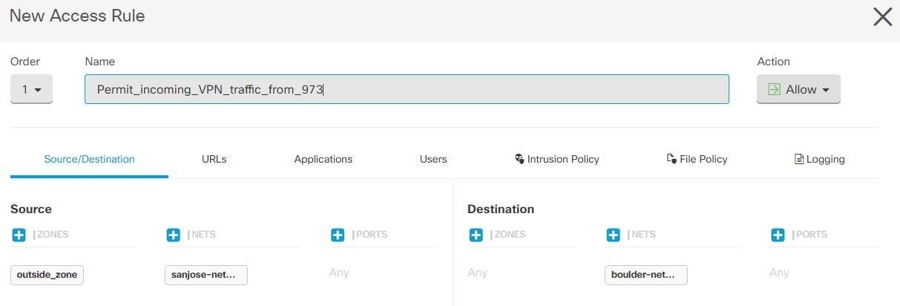
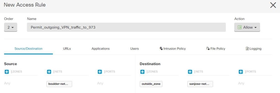
Configure AC policies: Configure AC policies for permitting bidirectional traffic between the protected networks behind both peers. These policies help the packets to traverse to the intended destination without being dropped.
After creating AC policies on one device, you must create similar policies on its peer. |
||
|
Step 2 |
If NAT is configured on either of the peer devices, you need to configure the NAT exempt rules manually. See Exempting Site-to-Site VPN Traffic from NAT. |
||
|
Step 3 |
Configure routing for receiving the return VPN traffic on each peer. For more information, see Configure Routing.
After configuring routing settings on one device, you must configure similar settings on its peer. |
Edit an Existing Security Cloud Control Site-To-Site VPN
The advanced configuration wizard is used by default to modify an existing site-to-site VPN configuration.
Procedure
|
Step 1 |
From the Security Cloud Control Home page, click Firewall. |
||
|
Step 2 |
In the left pane, choose . |
||
|
Step 3 |
Select the desired site-to-site VPN tunnel that you want to edit. |
||
|
Step 4 |
In the Actions pane, click Edit.
|
||
|
Step 5 |
In the Peer Devices section, you can modify the following device configurations: Configuration Name, VPN Access Interface, and Protected Networks.
|
||
|
Step 6 |
In the IKE Settings section, you can modify the following IKEv2 policies configurations:
|
||
|
Step 7 |
In the IPSec Settings section, you can modify the following IPSec configurations:
|
 button and enter the appropriate pre-shared keys for the devices.
The Point to point VPN is modified and updated with all the changes you have made.
Delete a Security Cloud Control Site-To-Site VPN Tunnel
Procedure
|
Step 1 |
From the Security Cloud Control Home page, click Firewall. |
|
Step 2 |
In the left pane, click to open the VPN page. |
|
Step 3 |
Select the desired site-to-site VPN tunnel that you want to delete. |
|
Step 4 |
In the Actions pane on the right, click Delete. |
The selected site-to-site VPN tunnel is deleted.
Exempt Site-to-Site VPN Traffic from NAT
When you have a site-to-site VPN connection defined on an interface, and you also have NAT rules for that interface, you can optionally exempt the traffic on the VPN from the NAT rules. You might want to do this if the remote end of the VPN connection can handle your internal addresses.
When you create the VPN connection, you can select the NAT Exempt option to create the rules automatically. However, this works only if your local protected network is connected through a single routed interface (not a bridge group member). If instead, the local networks in the connection reside behind two or more routed interfaces or one or more bridge group members, you need to configure the NAT exempt rules manually.
To exempt VPN traffic from NAT rules, you create an identity manual NAT rule for the local traffic when the destination is the remote network. Then, apply NAT to the traffic when the destination is anything else (for example, the Internet). If you have more than one interface for the local network, create rules for each interface. Also, consider the following suggestions:
-
If there is more than one local network in the connection, create a network object group to hold the objects that define the networks.
-
If you are including both IPv4 and IPv6 networks in the VPN, create separate identity NAT rules for each.
Consider the following example, which shows a site-to-site tunnel connecting the Boulder and San Jose offices. For traffic that you want to go to the Internet (for example from 10.1.1.6 in Boulder to www.example.com), you need a public IP address provided by NAT to access the Internet. The below example uses interface Port Address Translation (PAT) rules. However, for traffic that you want to go over the VPN tunnel (for example from 10.1.1.6 in Boulder to 10.2.2.78 in San Jose), you do not want to perform NAT; you need to exempt that traffic by creating an identity NAT rule. Identity NAT translates an address to the same address.
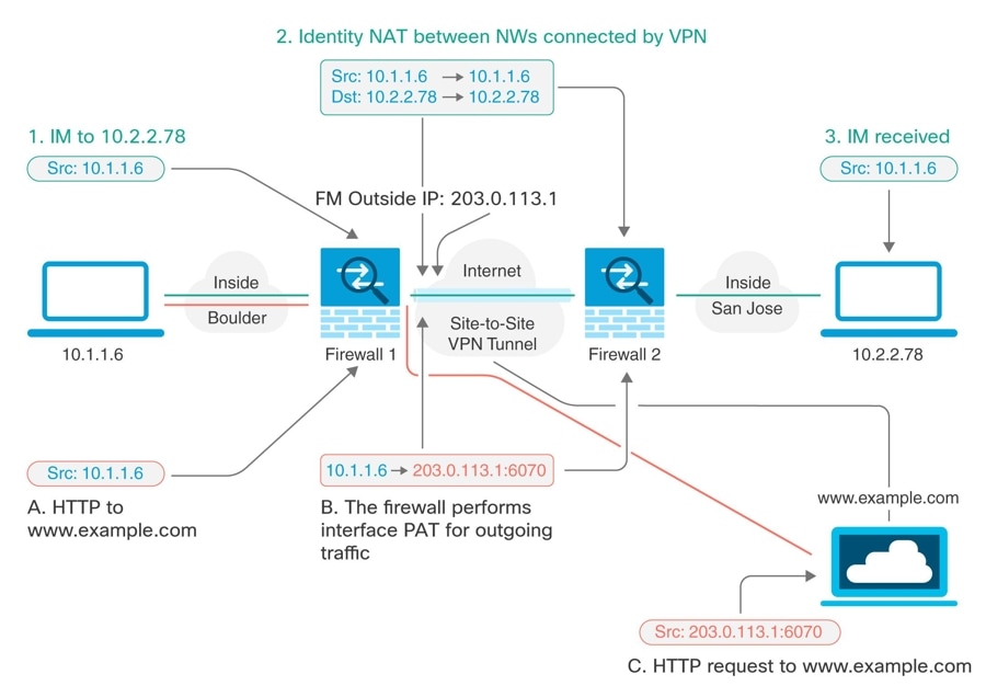
The following example explains the configuration for Firewall1 (Boulder). The example assumes that the inside interface is a bridge group, so you need to write the rules for each member interface. The process is the same if you have a single or multiple routed inside interfaces.
Note |
This example assumes IPv4 only. If the VPN also includes IPv6 networks, create parallel rules for IPv6. Note that you cannot implement IPv6 interface PAT, so you need to create a host object with a unique IPv6 address to use for PAT. |
Procedure
|
Step 1 |
From the Security Cloud Control Home page, click Firewall. |
|
Step 2 |
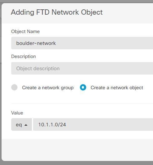
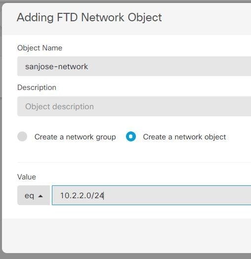
Create objects to define the various networks.
|
|
Step 3 |
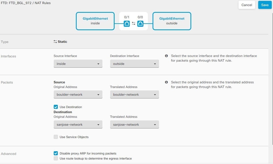
Configure manual identity NAT for the Boulder network when going over the VPN to San Jose on Firewall1 (Boulder).
|
|
Step 4 |
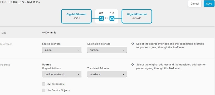
Configure manual dynamic interface PAT when going to the Internet for the inside Boulder network on Firewall1 (Boulder). Note: There might already be dynamic interface PAT rules for the inside interfaces, covering any IPv4 traffic, as these are created by default during initial configuration. However, the configuration is shown here for completeness. Before completing these steps, check whether a rule already exists that covers the inside interface and network, and skip this step if it does.
|
|
Step 5 |
Deploy configuration changes to Security Cloud Control. For more information, see Deploy Configuration Changes from Security Cloud Control to FTD. |
|
Step 6 |
If you are also managing Firewall2 (San Jose), you can configure similar rules for that device.
|
 .
.
Configure Static and Default Routes for FDM-Managed Devices
Define static routes on an FDM-managed device so it knows where to send packets bound for networks not directly connected to the interfaces on the system.
Consider creating a default route. This is the route for network 0.0.0.0/0. This route defines where to send packets whose egress interface cannot be determined by existing NAT translations, static NAT rules, or other static routes.
You might need other static routes if the default gateway cannot be used to get to all networks. For example, the default route is usually an upstream router on the outside interface. If there are additional inside networks that are not directly connected to the device, and they cannot be accessed through the default gateway, you need static routes for each of those inside networks.
You cannot define static routes for the networks that are directly connected to system interfaces. The system automatically creates these routes.
Site-to-Site VPN Configuration for Cloud-Delivered Firewall Management Center-managed Firewall Threat Defense
You can create site-to-site IPsec connections between a Cloud-Delivered Firewall Management Center-managed Firewall Threat Defense device and the following devices:
-
Firewall Threat Defense
-
Secure Firewall ASA
-
Multicloud Defense
Create a Site-to-Site VPN Tunnel Between Cloud-Delivered Firewall Management Center-managed Firewall Threat Defense Devices
Use the following procedure to create a site-to-site VPN tunnel between two Firewall Threat Defense devices managed by Cloud-Delivered Firewall Management Center.
Before you begin
There should not be any pending deployments on the Firewall Threat Defense device.
Procedure
|
Step 1 |
From the Security Cloud Control Home page, click Firewall. |
||||
|
Step 2 |
In the left pane, choose . |
||||
|
Step 3 |
Click the Create Tunnel ( |
||||
|
Step 4 |
In the Peer Selection area, provide the following information:
|
||||
|
Step 5 |
Click Next. |
||||
|
Step 6 |
In the Peer Details area, provide the following information:
|
||||
|
Step 7 |
Click Next. |
||||
|
Step 8 |
In the IKE Settings area, choose the IKE versions to use during Internet Key Exchange (IKE) negotiations and specify the privacy configurations: For more information on the IKE policies, see Configuring the Global IKE Policy.
|
||||
|
Step 9 |
Click Next. |
||||
|
Step 10 |
In the IPSec Settings area, specify the IPSec configurations for peer 1 and peer 2. The corresponding IKEV proposals are available depending on the selection that is made in the IKE Settings step. For more information on the IPSec settings, see the About IPSec Proposals.
|
||||
|
Step 11 |
In the Finish area, you will find a summary of the configurations you have completed. Read the configuration and then click Submit if you're satisfied. |
||||
|
Step 12 |
|||||
|
Step 13 |
Perform the following steps to deploy the configuration to a Cloud-Delivered Firewall Management Center-managed Firewall Threat Defense device:
|
Create a Site-to-Site VPN Tunnel Between Cloud-Delivered Firewall Management Center-Managed Firewall Threat Defense and Multicloud Defense
Note |
If you are a new customer and you want to use Security Cloud Control to configure a site-to-site VPN between Multicloud Defense and a Cloud-Delivered Firewall Management Center-managed Firewall Threat Defense device, contact Cisco Technical Assistance Center (Cisco TAC) to enable this feature. To manually configure a site-to-site VPN between ASA and Multicloud Defense, you can configure the VPN in the Multicloud Defense application and also on the Cloud-Delivered Firewall Management Center-managed Firewall Threat Defense device manually, and bring up the site-to-site VPN. |
You can create site-to-site IPsec connections between a Cloud-Delivered Firewall Management Center-managed Firewall Threat Defense and Multicloud Defense from the Security Cloud Control dashboard that complies with all relevant standards. After the VPN connection is established, the hosts behind the firewall can connect to the hosts behind the gateway through the secure VPN tunnel.
Multicloud Defense currently supports Amazon Web Services (AWS), Azure, Google Cloud Platform (GCP), and Oracle OCI cloud accounts.
Use the following procedure to create a VPN tunnel between a Cloud-Delivered Firewall Management Center-managed Firewall Threat Defense device and Multicloud Defense from the Security Cloud Control dashboard:
Before you begin
Ensure that the following prerequisites are met:
-
The Cloud-Delivered Firewall Management Center-managed Firewall Threat Defense device must not have any pending changes.
-
The Multicloud Defense must be onboarded to Security Cloud Control. See Connect Cloud Account.
-
The Multicloud Defense Gateway must be in the Active state.
-
The Multicloud Defense Gateway must be VPN enabled. See Enable VPN within the gateway.
-
Read the Multicloud Defense Gateway prerequisites and limitations for more information.
Procedure
|
Step 1 |
From the Security Cloud Control Home page, click Firewall. |
|
Step 2 |
In the navigation pane, choose . |
|
Step 3 |
Click the Create Tunnel ( |
|
Step 4 |
In the Peer Selection area, provide the following information:
|
|
Step 5 |
Click Next. |
|
Step 6 |
In the Peer Details area, provide the following information:
|
|
Step 7 |
Click Next. |
|
Step 8 |
In the Tunnel Details area, provide the following information:
|
|
Step 9 |
Click Next. |
|
Step 10 |
In the IKE Settings area, click Add IKEv2 and add the IKE version for the Internet Key Exchange (IKE) negotiations and specify the privacy configurations. |
|
Step 11 |
Click Next. |
|
Step 12 |
In the IPSec Settings area, click Add IKEv2 IPSec Proposals and select the IKE IPSec configuration. The proposals are available depending on the selection that is made in the IKE Settings step. See Configuring IPSec Proposals. |
|
Step 13 |
Click Next. |
|
Step 14 |
In the Finish area, review the configuration and continue further only if you’re satisfied with the configuration. |
|
Step 15 |
Click Submit. The configurations are pushed to the Multicloud Defense Gateway. |
|
Step 16 |
Perform the following steps to deploy the configuration to a Cloud-Delivered Firewall Management Center-managed Firewall Threat Defense device:
|
Create a Site-to-Site VPN Between Cloud-Delivered Firewall Management Center-managed Firewall Threat Defense and Secure Firewall ASA
Before you begin
There should not be any pending deployments on the Firewall Threat Defense device.
Procedure
|
Step 1 |
From the Security Cloud Control Home page, click Firewall. |
||||
|
Step 2 |
In the navigation pane, choose . |
||||
|
Step 3 |
Click the Create Tunnel ( |
||||
|
Step 4 |
In the Peer Selection area, provide the following information:
|
||||
|
Step 5 |
Click Next. |
||||
|
Step 6 |
In the Peer Details area, provide the following information:
|
||||
|
Step 7 |
Click Next. |
||||
|
Step 8 |
In the Tunnel Details area, provide the following information:
|
||||
|
Step 9 |
Click Next. |
||||
|
Step 10 |
In the IKE Settings area, choose the IKE versions to use during Internet Key Exchange (IKE) negotiations and specify the privacy configurations: For more information on the IKE policies, see Configuring the Global IKE Policy.
|
||||
|
Step 11 |
Click Next. |
||||
|
Step 12 |
In the IPSec Settings area, specify the IPSec configurations for peer 1 and peer 2. The corresponding IKEV proposals are available depending on the selection that is made in the IKE Settings step. For more information on the IPSec settings, see the About IPSec Proposals.
|
||||
|
Step 13 |
Click Next. |
||||
|
Step 14 |
In the Finish area, you will find a summary of the configurations you have completed. Read the configuration and then click Submit if you're satisfied. |
||||
|
Step 15 |
Perform the following steps to deploy the configuration to a Cloud-Delivered Firewall Management Center-managed Firewall Threat Defense device:
|
Site-to-Site VPN for Secure Firewall ASA
Security Cloud Control supports these aspects of site-to-site VPN functionality on Secure Firewall ASA devices:
-
Both IPsec IKEv1 & IKEv2 protocols are supported.
-
Automatic or manual pre-shared keys for authentication.
-
IPv4 and IPv6. All combinations of inside and outside are supported.
-
IPsec IKEv2 site-to-site VPN topologies provide configuration settings to comply with Security Certifications.
-
Static and dynamic interfaces.
-
Support the static or dynamic IP address for the extranet device as an endpoint.
Configure Site-to-Site VPN Connections with Dynamically Addressed Peers
Security Cloud Control allows you to create a site-to-site VPN connection between peers when one of the peers' VPN interface IP address is not known or when the interface obtains its address from a DHCP server. Any dynamic peer whose preshared key, IKE settings, and IPsec configurations match with another peer can establish a site-to-site VPN connection.
Consider two peers, A and B. The static peer is a device whose IP address of its VPN interface is fixed and a dynamic peer is a device whose IP address of the VPN interface is not known or has a temporary IP address.
The following use cases describe different scenarios for establishing a secure site-to-site VPN connection with dynamically-addressed peers:
-
A is a static peer, and B is a dynamic peer or conversely.
-
A is a static peer, and B is a dynamic peer with a resolved IP address from the DHCP server or conversely.
-
A is a dynamic peer, and B is an extranet device with a static or dynamic IP address.
-
A is a dynamic peer with a resolved IP address from the DHCP server, and B is an Extranet device with a static or dynamic IP address.
Note |
If the IP address of the interface is changed by using a local manager like Adaptive Security Device Manager (ASDM), the Configuration Status of that peer in Security Cloud Control shows "Conflict Detected". When you resolve this out-of-band change, the Configuration Status of the other peer changes to the "Not Synced" state. You must deploy the Security Cloud Control configuration to the device which is in "Not Synced" state. |
Typically, the dynamic peer must be the one that initiates the connection as the other peer would not know the IP address of the dynamic peer. When the remote peer attempts to establish the connection, the other peer validates the connection using the preshared key, IKE settings, and IPsec configurations.
Because the VPN connection is established only after the remote peer initiates the connection, any outbound traffic that matches access control rules that allow traffic in the VPN tunnel will be dropped until that connection is established. This ensures that data does not leave your network without the appropriate encryption and VPN protection.
Note |
A site-to-site VPN connection cannot be configured in the following scenario: If a device has more than one dynamic peer connection.
|
Secure Firewall ASA Site-to-Site VPN Guidelines and Limitations
-
Security Cloud Control does not support a crypto-acl to design the interesting traffic for S2S VPN. It only supports protected networks.
-
Whenever IKE ports 500/4500 are in use or when there are some PAT translations that are active, the site-to-site VPN cannot be configured on the same ports as it fails to start the service on those ports.
-
Transport mode is not supported only tunnel mode. IPsec tunnel mode encrypts the entire original IP datagram which becomes the payload in a new IP packet. Use tunnel mode when the firewall is protecting traffic to and from hosts positioned behind a firewall. Tunnel mode is the normal way regular IPsec is implemented between two firewalls (or other security gateways) that are connected over an untrusted network, such as the Internet.
-
For this release, only PTP topology is supported, containing one or more VPN tunnels. Point-to-point (PTP) deployments establish a VPN tunnel between two endpoints.
Guidelines for Virtual Tunnel Interfaces
-
VTIs are only configurable in IPsec mode. To terminate GRE tunnels on an Secure Firewall ASA is unsupported.
-
You can use dynamic or static routes for traffic using the tunnel interface.
-
The MTU for VTIs is automatically set, according to the underlying physical interface. However, if you change the physical interface MTU after the VTI is enabled, you must disable and reenable the VTI to use the new MTU setting.
-
If Network Address Translation has to be applied, the IKE and ESP packets will be encapsulated in the UDP header.
-
IKE and IPsec security associations will be re-keyed continuously regardless of data traffic in the tunnel. This ensures that VTI tunnels are always up.
-
Tunnel group name must match what the peer will send as its IKEv1 or IKEv2 identity.
-
For IKEv1 in LAN-to-LAN tunnel groups, you can use names which are not IP addresses, if the tunnel authentication method is digital certificates and/or the peer is configured to use aggressive mode.
-
VTI and crypto map configurations can co-exist on the same physical interface, provided the peer address configured in the crypto map and the tunnel destination for the VTI are different.
-
By default, all traffic through VTI is encrypted.
-
By default, the security level for VTI interfaces is 0.
-
Access list can be applied on a VTI interface to control traffic through VTI.
-
Only BGP is supported over VTI.
-
If Secure Firewall ASA is terminating IOS IKEv2 VTI clients, disable the config-exchange request on IOS, because Secure Firewall ASA cannot retrieve the mode-CFG attributes for this L2L session initiated by an IOS VTI client.
-
IPv6 is not supported.
Create a Site-to-Site VPN Tunnel Between Secure Firewall ASA
Use the following procedure to create a site-to-site VPN tunnel between two ASAs or an ASA with an Extranet device:
Procedure
|
Step 1 |
From the Security Cloud Control Home page, click Firewall. |
||||
|
Step 2 |
In the left pane, click . |
||||
|
Step 3 |
Click the Create Tunnel ( |
||||
|
Step 4 |
|||||
|
Step 5 |
In the Peer Selection area, provide the following information:
|
||||
|
Step 6 |
Click Next. |
||||
|
Step 7 |
In the Peer Details area, provide the following information:
|
||||
|
Step 8 |
Click Next. |
||||
|
Step 9 |
(Applicable to Route Based) In the Tunnel Details, the VTI Address fields are automatically filled once the peer devices are configured in the previous step. If necessary, you can manually enter an IP address that will be used as the new VTI. |
||||
|
Step 10 |
In the IKE Settings area, choose the IKE versions to use during Internet Key Exchange (IKE) negotiations and specify the privacy configurations: For more information on the IKE policies, see Global IKE policies.
|
||||
|
Step 11 |
Click Next. |
||||
|
Step 12 |
In the IPSec Settings area, specify the IPSec configurations for peer 1 and peer 2. The corresponding IKEV proposals are available depending on the selection that is made in the IKE Settings step. For more information on the IPSec settings, see the Global IKE policies.
|
||||
|
Step 13 |
In the Finish area, review the configuration and continue further only if you’re satisfied with the configuration. By default, the Deploy changes to ASA immediately check box is checked to deploy the configurations immediately to the ASA device after clicking Submit. If you want to review and deploy the configurations manually later, then uncheck this check box. |
Create a Site-to-Site VPN Between ASA and Multicloud Defense Gateway
Note |
If you are a new customer and you want to use Security Cloud Control to configure a site-to-site VPN between Multicloud Defense and an ASA device, contact Cisco Technical Assistance Center (Cisco TAC) to enable this feature. To manually configure a site-to-site VPN between ASA and Multicloud Defense, you can configure the VPN in the Multicloud Defense application and also on the ASA device manually, and bring up the site-to-site VPN. |
You can create site-to-site IPsec connections between an ASA and a Multicloud Defense Gateway that complies with all relevant standards. After the VPN connection is established, the hosts behind the firewall can connect to the hosts behind the gateway through the secure VPN tunnel.
Multicloud Defense currently supports Amazon Web Services (AWS), Azure, Google Cloud Platform (GCP), and Oracle OCI cloud accounts.
Use the following procedure to create a VPN tunnel between an ASA device that is managed by Security Cloud Control and Multicloud Defense Gateway from the Security Cloud Control dashboard:
Before you begin
Ensure that the following prerequisites are met:
-
The ASA device must not have any pending changes.
-
Create a BGP profile in the ASA console prior to creating a VPN tunnel. See Configure ASA Border Gateway Protocol for more information.
-
The Multicloud Defense Gateway must be in the Active state.
-
The Multicloud Defense Gateway must be VPN enabled. See Enable VPN within the gateway.
-
Read the ASA site-to-site VPN limitations and guidelines for more information.
-
Read the Multicloud Defense Gateway prerequisites and limitations for more information.
Procedure
|
Step 1 |
From the Security Cloud Control Home page, click Firewall. |
|
Step 2 |
In the left pane, choose . |
|
Step 3 |
Click the Create Tunnel ( |
|
Step 4 |
In the Peer Selection area, provide the following information:
|
|
Step 5 |
Click Next. |
|
Step 6 |
In the Peer Details area, provide the following information:
|
|
Step 7 |
Click Next. |
|
Step 8 |
In the Tunnel Details area, provide the following information:
|
|
Step 9 |
Click Next. |
|
Step 10 |
In the IKE Settings area, Security Cloud Control generates a default Local Pre-Shared Key. This is a secret key string that is configured on the peers. IKE uses this key during the authentication phase. It is used to verify each other when establishing a tunnel between the peers. |
|
Step 11 |
In the Finish area, review the configuration and continue further only if you’re satisfied with the configuration. By default, the Deploy changes to ASA immediately check box is checked to deploy the configurations immediately to the ASA device after clicking Submit. If you want to review and deploy the configurations manually later, then uncheck this check box. |
|
Step 12 |
Click Submit. The configurations are pushed to the Multicloud Defense Gateway. |
The VPN page in Security Cloud Control shows the site-to-site tunnel created between the peers. You will be able to see the corresponding tunnel in the Multicloud Defense Gateway portal.
Exempt Site-to-Site VPN Traffic from NAT
When you have a site-to-site VPN connection defined on an interface, and you also have NAT rules for that interface, you can optionally exempt the traffic on the VPN from the NAT rules. You might want to do this if the remote end of the VPN connection can handle your internal addresses.
When you create the VPN connection, you can select the NAT Exempt option to create the rules automatically. However, this works only if your local protected network is connected through a single routed interface (not a bridge group member). If instead, the local networks in the connection reside behind two or more routed interfaces or one or more bridge group members, you need to configure the NAT exempt rules manually.
To exempt VPN traffic from NAT rules, you create an identity manual NAT rule for the local traffic when the destination is the remote network. Then, apply NAT to the traffic when the destination is anything else (for example, the Internet). If you have more than one interface for the local network, create rules for each interface. Also, consider the following suggestions:
-
If there is more than one local network in the connection, create a network object group to hold the objects that define the networks.
-
If you are including both IPv4 and IPv6 networks in the VPN, create separate identity NAT rules for each.
Consider the following example, which shows a site-to-site tunnel connecting the Boulder and San Jose offices. For traffic that you want to go to the Internet (for example from 10.1.1.6 in Boulder to www.example.com), you need a public IP address provided by NAT to access the Internet. The below example uses interface Port Address Translation (PAT) rules. However, for traffic that you want to go over the VPN tunnel (for example from 10.1.1.6 in Boulder to 10.2.2.78 in San Jose), you do not want to perform NAT; you need to exempt that traffic by creating an identity NAT rule. Identity NAT translates an address to the same address.
The following example explains the configuration for Firewall1 (Boulder). The example assumes that the inside interface is a bridge group, so you need to write the rules for each member interface. The process is the same if you have a single or multiple routed inside interfaces.
Note |
This example assumes IPv4 only. If the VPN also includes IPv6 networks, create parallel rules for IPv6. Note that you cannot implement IPv6 interface PAT, so you need to create a host object with a unique IPv6 address to use for PAT. |
Procedure
|
Step 1 |
From the Security Cloud Control Home page, click Firewall. |
|
Step 2 |
Create objects to define the various networks.
|
|
Step 3 |
Configure manual identity NAT for the Boulder network when going over the VPN to San Jose on Firewall1 (Boulder).
|
|
Step 4 |
Configure manual dynamic interface PAT when going to the Internet for the inside Boulder network on Firewall1 (Boulder). Note: There might already be dynamic interface PAT rules for the inside interfaces, covering any IPv4 traffic, as these are created by default during initial configuration. However, the configuration is shown here for completeness. Before completing these steps, check whether a rule already exists that covers the inside interface and network, and skip this step if it does.
|
|
Step 5 |
Deploy configuration changes to Security Cloud Control. For more information, see Deploy Configuration Changes from Security Cloud Control to FTD. |
|
Step 6 |
If you are also managing Firewall2 (San Jose), you can configure similar rules for that device.
|
Monitor Site-to-Site Virtual Private Networks
Security Cloud Control allows you to monitor, modify, and delete existing or newly created site-to-site VPN configurations on onboarded FDM-managed devices.
Check Site-to-Site VPN Tunnel Connectivity
Use the Check Connectivity button to trigger a real-time connectivity check against the tunnel to identify whether the tunnel is currently active or idle. Unless you click the on-demand connectivity check button, a check across all tunnels, available across all onboarded devices, occurs once an hour.
Note |
|
To check tunnel connectivity from the VPN page:
Procedure
|
Step 1 |
From the Security Cloud Control Home page, click Firewall. |
|
Step 2 |
In the left pane, choose . |
|
Step 3 |
Search and filter the list of tunnels for your site-to-site VPN tunnel and select it. |
|
Step 4 |
In the Actions pane at the right, click Check Connectivity. |
Site-To-Site VPN Dashboard
Security Cloud Control provides a consolidated information about site-to-site VPN connections created in the tenant.
-
From the Security Cloud Control Home page, click Firewall.
-
In the left pane, click Secure Connections > Site to Site VPN. The Site-to-Site VPN provides the information in the following widgets:
-
Sessions & Insights: Displays a bar graph representing Active VPN Tunnels and Idle VPN Tunnels, each in appropriate colors.
-
Issues: Shows the total number of tunnels detected with issues.
-
Pending Deploy: Shows the total number of tunnels with pending deployment.
By clicking on a value in the pie chart or any link in the widget, the site-to-site VPN listing page is displayed with a filter based on the selected value. For instance, in the VPN Tunnel Status widget, on clicking the Active VPN Tunnels, you will be directed to the site-to-site VPN listing page with the Active status filter applied, showing only the active tunnels.
Identify VPN Issues
Security Cloud Control can identify VPN issues on FTD. (This feature is not yet available for AWS VPC site-to-site VPN tunnels.) This article describes:
Find VPN Tunnels with Missing Peers
The "Missing IP Peer" condition is more likely to occur on ASA devices than FDM-managed devices.
Procedure
|
Step 1 |
From the Security Cloud Control Home page, click Firewall. |
|
Step 2 |
In the left pane, click to open the VPN page. |
|
Step 3 |
Select Table View. |
|
Step 4 |
Open the Filter panel by clicking the filter icon |
|
Step 5 |
Check Detected Issues. |
|
Step 6 |
Select each device reporting an issue |
 and look in the Peers pane at the right. One peer name will be listed.
 Find VPN Peers with Encryption Key Issues
Use this approach to locate VPN Peers with encryption key issues such as:
-
IKEv1 or IKEv2 keys are invalid, missing, or mismatched
-
Obsolete or low encryption tunnels
Procedure
|
Step 1 |
From the Security Cloud Control Home page, click Firewall. |
|
Step 2 |
In the left pane, click to open the VPN page. |
|
Step 3 |
Select Table View. |
|
Step 4 |
Open the Filter panel by clicking the filter icon |
|
Step 5 |
Select each device reporting an issue |
|
Step 6 |
Click on View Peers for one of the devices. |
|
Step 7 |
Double-click the device reporting the issue in the Diagram View. |
|
Step 8 |
Click Key Exchange in the Tunnel Details panel at the bottom. You will be able to view both devices and diagnose the key issue from that point. |
Find Incomplete or Misconfigured Access Lists Defined for a Tunnel
The "incomplete or misconfigured access-list" condition could only occur on ASA devices.
Procedure
|
Step 1 |
From the Security Cloud Control Home page, click Firewall. |
|
Step 2 |
In the left pane, click to open the VPN page. |
|
Step 3 |
Select Table View. |
|
Step 4 |
Open the Filter panel by clicking the filter icon |
|
Step 5 |
Select each device reporting an issue |
|
Step 6 |
Click on View Peers for one of the devices. |
|
Step 7 |
Double-click the device reporting the issue in the Diagram View. |
|
Step 8 |
Click Tunnel Details in the Tunnel Details panel at the bottom. You will see the message, "Network Policy: Incomplete" |
Find Issues in Tunnel Configuration
The tunnel configuration error can occur in the following scenarios:
-
When the IP address of a site-to-site VPN interface changes, the "Peer IP Address Value has changed".
-
When the IKE value of a VPN tunnel doesn't match the other VPN tunnel, the "IKE value Mismatch" message appears.
Procedure
|
Step 1 |
From the Security Cloud Control Home page, click Firewall. |
|
Step 2 |
In the left pane, click to open the VPN page. |
|
Step 3 |
Select Table View. |
|
Step 4 |
Open the Filter panel by clicking the filter icon |
|
Step 5 |
In the Tunnel Issues, click Detected Issues to view the VPN configuration reporting errors. You can view the configuration reporting issues |
|
Step 6 |
Select the VPN configuration reporting issues. |
|
Step 7 |
In the Peers pane on the right, the Next Step: Resolve Tunnel Configuration Issues. |
Resolve Tunnel Configuration Issues
This procedure attempts to resolve these tunnel configuration issues:
-
When the IP address of a site-to-site VPN interface changes, the "Peer IP Address Value has changed".
-
When the IKE value of a VPN tunnel doesn’t match the other VPN tunnel, the "IKE value Mismatch" message appears.
See Find Issues in Tunnel Configuration for more information.
Procedure
|
Step 1 |
In the left pane, click . |
|
Step 2 |
Click the Devices tab. |
|
Step 3 |
Click the appropriate device type tab and select the device associated with the VPN configuration reporting an issue. |
|
Step 4 |
|
|
Step 5 |
In the left pane, click to open the VPN page. |
|
Step 6 |
Select the VPN configuration reporting this issue. |
|
Step 7 |
In the Actions pane, click the Edit icon. |
|
Step 8 |
Click Next in each step until you click the Finish button in step 4. |
|
Step 9 |
Search and Filter Site-to-Site VPN Tunnels
Use the filter sidebar  in combination with the search field to focus your search of VPN tunnels presented in the VPN tunnel diagram.
Procedure
|
Step 1 |
From the Security Cloud Control Home page, click Firewall. |
|
Step 2 |
Choose . |
|
Step 3 |
Click the filter icon |
|
Step 4 |
Use these filters to refine your search:
|
|
Step 5 |
You can also search the filtered results by device name or IP address by entering that information in the search bar. The search is case-insensitive. |
Onboard an Unmanaged Site-to-Site VPN Peer
Security Cloud Control will discover a site-to-site VPN tunnel when one of the peers is onboarded. If the second peer is not managed by Security Cloud Control, you can filter the list of VPN tunnels to find the unmanaged device and onboard it:
Procedure
|
Step 1 |
From the Security Cloud Control Home page, click Firewall. |
|
Step 2 |
In the left pane, click to open the VPN page. |
|
Step 3 |
Select Table View. |
|
Step 4 |
Open the filter panel by clicking |
|
Step 5 |
Check Unmanaged. |
|
Step 6 |
Select a tunnel from the table from the results. |
|
Step 7 |
In the Peers pane on the right, click Onboard Device and follow the instructions on the screen. |
View IKE Object Details of Site-To-Site VPN Tunnels
You can view the details of the IKE objects configured on the peers/devices of the selected tunnel. These details appear in a tree structure in a hierarchy based on the priority of the IKE policy object.
Note |
Extranet devices don't show the IKE Objects details. |
Procedure
|
Step 1 |
From the Security Cloud Control Home page, click Firewall. |
|
Step 2 |
In the left pane, click to open the VPN page. |
|
Step 3 |
In the VPN Tunnels page, click the name of the VPN tunnel that connects the peers. |
|
Step 4 |
Under Relationships on the right, expand the object that you want to see its details. |
View Last Successful Site-to-Site VPN Tunnel Establishment Date
This information typically provides the date and time when the VPN tunnel was last successfully established, ensuring connectivity between the two sites. Accessing this data can help you monitor VPN health and troubleshoot any connectivity issues that might arise.
Procedure
|
Step 1 |
From the Security Cloud Control Home page, click Firewall. |
||
|
Step 2 |
In the left pane, click to open the VPN page. |
||
|
Step 3 |
The VPN Tunnels page displays all the site-to-site VPN tunnels configured across your managed devices. You can click a tunnel to view more details in the right pane.
The Last Active field shows the date and time the VPN tunnel was successfully established. |
View Site-to-Site VPN Tunnel Information
The site-to-site VPN table view is a complete listing of all site-to-site VPN tunnels available across all devices onboarded to Security Cloud Control. A tunnel only exists once in this list. Clicking on a tunnel listed in the table provides an option in the right side bar to navigate directly to a tunnel's peers for further investigation.
In cases where Security Cloud Control does not manage both sides of a tunnel, you can click Onboard Device to open the main onboarding page an onboard the unmanaged peer. In cases where Security Cloud Control manages both side of a tunnel, the Peer 2 column contains the name of the managed device. However, in the case of an AWS VPC, the Peer 2 column contains the IP address of the VPN gateway.
To view site-to-site VPN connections in the table view:
Procedure
|
Step 1 |
From the Security Cloud Control Home page, click Firewall. |
||
|
Step 2 |
In the left pane, click to open the VPN page. |
||
|
Step 3 |
The VPN Tunnels page displays all the site-to-site VPN tunnels configured across your managed devices. You can click on a tunnel to view more details in the right pane.
|
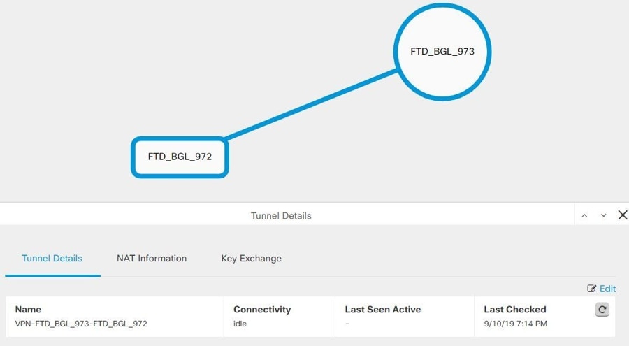
Site-to-Site VPN Global View
This is an example fo the global view. In the illustration, 'FTD_BGL_972' has a site-to-site connection with FTD_BGL_973 and
FTD_BGL_974 devices. 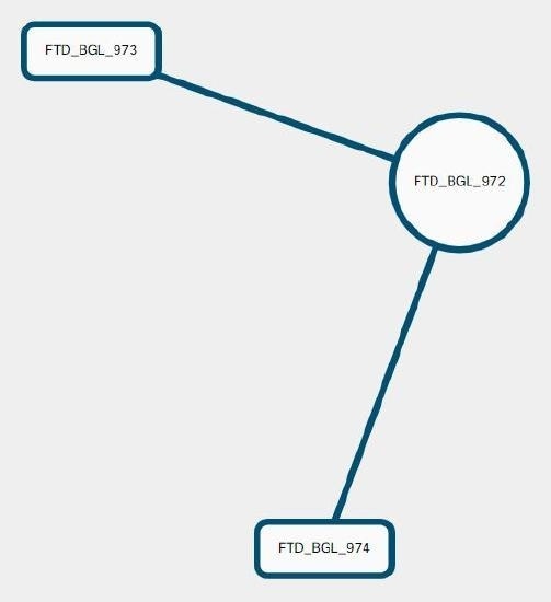
Procedure
|
Step 1 |
From the Security Cloud Control Home page, click Firewall. |
|
Step 2 |
In the left pane, click . |
|
Step 3 |
Click the Global view button. |
|
Step 4 |
Use Search and Filter Site-to-Site VPN Tunnels to find a specific tunnel, or zoom into the Global View graphic to find the VPN gateway and its peers that you are looking for. |
|
Step 5 |
Select one of the peers represented in the Global View. |
|
Step 6 |
Click View Details. |
|
Step 7 |
Click the other end of the VPN tunnel and Security Cloud Control displays Tunnel Details, NAT Information, and Key Exchange information for that connection:
|
Site-to-Site VPN Tunnels Pane
The Tunnels pane displays a list of all the tunnels associated with a particular VPN gateway. For site-to-site VPN connections between your VPN gateway and an AWS VPC, the tunnels pane shows all the tunnels from your VPN gateway to the VPC. Since each site-to-site VPN connection between your VPN gateway and an AWS VPC has two tunnels, you will see double the number of tunnels you normally would for other devices.
VPN Gateway Details
Displays the number of peers connected to the VPN gateway and the IP address of the VPN gateway. This is only visible in the VPN Tunnels page.
View Peer
After you select a site-to-site VPN peer pair, the peers pane lists the two devices in the pair and allows you to click View Peer for one of the devices. By clicking View Peer, you see any other site-to-site peer that device is associated with. This is visible in the Table view and in the Global view.
Delete a Security Cloud Control Site-To-Site VPN Tunnel
Procedure
|
Step 1 |
From the Security Cloud Control Home page, click Firewall. |
|
Step 2 |
In the left pane, click to open the VPN page. |
|
Step 3 |
Select the desired site-to-site VPN tunnel that you want to delete. |
|
Step 4 |
In the Actions pane on the right, click Delete. |
The selected site-to-site VPN tunnel is deleted.
 >
> 
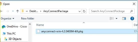
 to upload the package. If the checksum doesn't match, the AnyConnect package upload fails. You can see the device's workflow
tab for more details about the failure.
to upload the package. If the checksum doesn't match, the AnyConnect package upload fails. You can see the device's workflow
tab for more details about the failure.
 to upload the package.
  icon appearing beside the existing AnyConnect package. If there are multiple versions of AnyConnect package for an operating
system, select the package you want to replace from the list and click
icon appearing beside the existing AnyConnect package. If there are multiple versions of AnyConnect package for an operating
system, select the package you want to replace from the list and click  icon appearing beside the AnyConnect package that you want to delete. If there are multiple versions of AnyConnect package
for an operating system, select the package you want to delete from the list. The existing package disappears from the corresponding
field.
icon appearing beside the AnyConnect package that you want to delete. If there are multiple versions of AnyConnect package
for an operating system, select the package you want to delete from the list. The existing package disappears from the corresponding
field.
 in the
  to perform the following on the
  to copy the instructions to the clipboard, and then distribute them to your users.
 ) button (
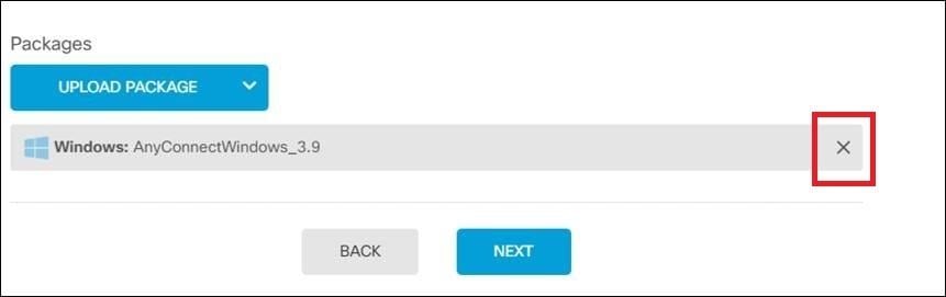
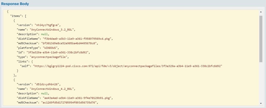
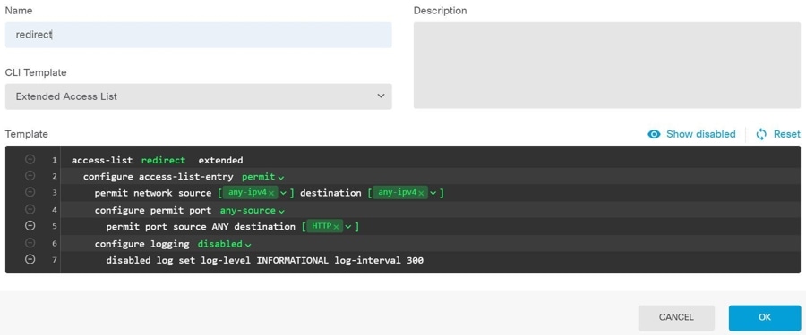
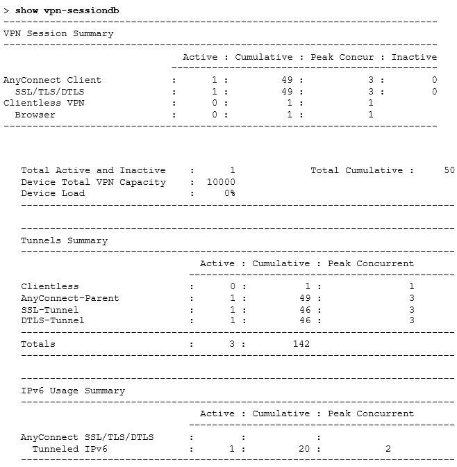
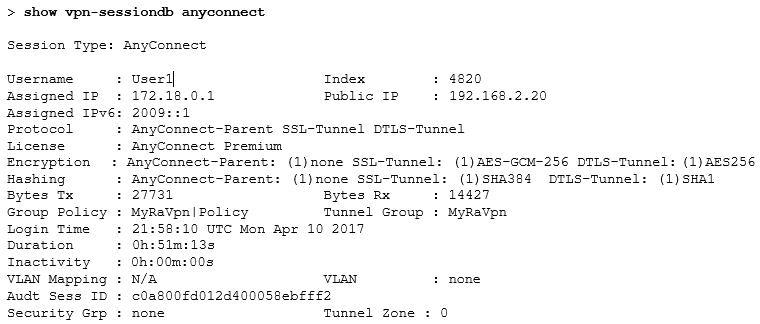
 ) to open a summary of the connection profile and connection instructions. Under
  appearing on the right corner of the screen.
 located to the right of the columns and select or deselect the columns you want.
 icon on the top right corner.
  Feedback