Networking Requirements
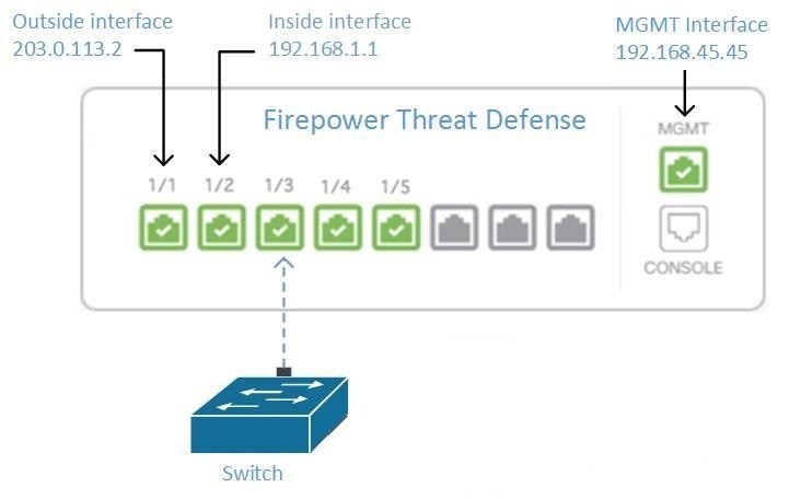
Managing an FDM-Managed Device from the Inside Interface
Managing an FDM-managed device using the inside interface may be desirable if the dedicated MGMT interface is assigned an address that is not routable within your organization; for example, it might only be reachable from within your data center or lab.
Remote Access VPN Requirement
If the FDM-managed device you manage with Security Cloud Control will be managing Remote Access VPN (RA VPN) connections, Security Cloud Control must manage the device using the inside interface.
What to do next:
Continue to Manage an FDM-Managed Device from the Inside Interface for the procedure for configuring the FDM-managed device.
Manage an FDM-Managed Device from the Inside Interface
This configuration method:
-
Assumes that the FDM-managed device has not been on-boarded to Security Cloud Control.
-
Configures a data interface as the inside interface.
-
Configures the inside interface to receive MGMT traffic (HTTPS).
-
Allows the address of the cloud connector to reach the inside interface of the device.
Before you begin
Procedure
|
Step 1 |
Log in to the Secure Firewall Device Manager. |
|
Step 2 |
In the System Settings menu, click Management Access. |
|
Step 3 |
Click the Data Interfaces tab and click Create Data Interface.
|
|
Step 4 |
Deploy the change. You can now manage the device using the inside interface. |
What to do next
What if you are using a Cloud Connector?
Use the procedure above and add these steps:
-
Add a step to "NAT" the outside interface to (203.0.113.2) to the inside interface (192.168.1.1). See Interface Addresses.
-
In step 3c of the procedure above, your "Allowed Network" is a network group object containing the public IP addresses of the cloud connector.
-
Add a step that creates an Access Control rule allowing access to the outside interface (203.0.113.2) from the public IP addresses of the cloud connector. See for a list of all the Cloud Connector IP addresses for the various Security Cloud Control regions.
Onboard the FDM-Managed Device
The recommended way of onboarding the FDM-managed device to Security Cloud Control is to use the registration token onboarding approach. After you configure the inside interface to allow management access from the Cloud Connector to the FDM-managed device, onboard the FDM-managed device with the user name and password. See Onboard an FDM-managed Device Using Username, Password, and IP Address for more information. You will connect using the IP address of the inside interface. In our scenario above, that address is 192.168.1.1.
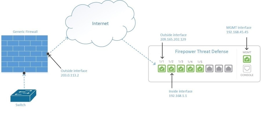
Managing an FDM-Managed Device from the Outside Interface
Managing an Cloud-Delivered Firewall Management Center device from the outside interface may be desirable if you have one public IP address assigned to a branch office and Security Cloud Control is managed using a Cloud Connector at another location.
This configuration doesn't mean that the physical MGMT interface is no longer the device's management interface. If you were in the office where the Cloud-Delivered Firewall Management Center device was located, you would be able to connect to the address of the MGMT interface and manage the device directly.
Remote Access VPN Requirement
If the device you manage with Cloud-Delivered Firewall Management Center will be managing Remote Access VPN (RA VPN) connections, Cloud-Delivered Firewall Management Center will not be able to manage the Cloud-Delivered Firewall Management Center device using the outside interface. See Managing an FDM-Managed Device from the Inside Interface instead.
What to do next:
Continue to Manage the FDM-Managed Device's Outside Interface for the procedure for configuring the Cloud-Delivered Firewall Management Center device.
Manage the FDM-Managed Device's Outside Interface
This configuration method:
-
Assumes that the FDM-managed device has not been on-boarded to Security Cloud Control.
-
Configures a data interface as the outside interface.
-
Configures management access on the outside interface.
-
Allows the public IP address of the cloud connector (after it has been NAT'd through the firewall) to reach the outside interface.
Before you begin
Procedure
|
Step 1 |
Log in to the Secure Firewall Device Manager. |
|
Step 2 |
In the System Settings menu, click Management Access. |
|
Step 3 |
Click the Data Interfaces tab and click Create Data Interface.
|
|
Step 4 |
Create an Access Control policy in Secure Firewall Device Manager that allows management traffic (HTTPS) from the public IP address of the SDC or cloud connector, to the outside interface of your FDM-managed device. In this scenario, the source address would be 203.0.113.2 and the source protocol would be HTTPS; the destination address would be 209.165.202.129 and the protocol would be HTTPS. |
|
Step 5 |
Deploy the change. You can now manage the device using the outside interface. |
What to do next
What if you are using a cloud connector?
The process is very similar, except for two things:
-
In step 3c of the procedure above, your "Allowed Network" is a network group object containing the public IP addresses of the cloud connector. See Connecting Devices to Security Cloud Control Through the Cloud Connector for a list of Cloud Connector IP addresses for the various Security Cloud Control regions.
-
In step 4 of the procedure above, you create an Access Control rule that allows access to the outside interface from the public IP addresses of the cloud connector.
The registration token onboarding approach is the recommended way of onboarding the FDM-managed device to Security Cloud Control. After you configure the outside interface to allow management access from the cloud connector, onboard the FDM-managed device. You will connect using the IP address of the outside interface. In our scenario, that address is 209.165.202.129.

 Install DUO Security. We recommend installing the Duo Security app on a mobile phone. Review
 ) icon, and perform device actions using the options in the right pane. See
 .
.


 , and check
  .
.
 .
.
 in the
  appearing beside the object name or network group to modify them.
 arrow in
  arrow in

 .
.
 .
.
 Feedback