Prepare for Installation
The following sections describe safety warnings, general maintenance guidelines, and safety recommendations that you must read before installing and using the service module:
The documentation set for this product strives to use bias-free language. For the purposes of this documentation set, bias-free is defined as language that does not imply discrimination based on age, disability, gender, racial identity, ethnic identity, sexual orientation, socioeconomic status, and intersectionality. Exceptions may be present in the documentation due to language that is hardcoded in the user interfaces of the product software, language used based on RFP documentation, or language that is used by a referenced third-party product. Learn more about how Cisco is using Inclusive Language.
This section describes how to install the Cisco Catalyst Service Modules on the Cisco Catalyst 8300 Series Edge Platforms. The service modules supported on the on the Cisco Catalyst 8300 Series Edge Platforms are:
C-SM-16P4M2X
C-SM-40P8M2X
For additional information on the supported SMs, see the Cisco Catalyst 8300 Series Edge Platforms' datasheet on cisco.com.
 Note |
|
The following sections describe safety warnings, general maintenance guidelines, and safety recommendations that you must read before installing and using the service module:
Ratcheting torque screwdriver with a number-2 Phillips head that exerts a maximum of 15 pound-force inches (lbf-in.) of pressure
Wire-stripping tools
12-gauge copper ground wire (insulated or not) for the single-hole ground connection
Single-hole ground lug and screw (included in the accessory kit)
Four leads of 14-gauge copper wire
To remove the service modules from the chassis, perform these steps:
|
Step 1 |
Read the Safety Warnings before you perform any module replacement. |
|
Step 2 |
Locate the service module(s) to be removed |
|
Step 3 |
Unscrew the captive mounting screws on the module faceplate using a number 1 Phillips or flat-blade screwdriver. |
|
Step 4 |
Pull the module out of the chassis. |
|
Step 5 |
For the module, keep the latches in open position and pull the module out of the chassis. |
|
Step 6 |
Place the service module in an antistatic bag to protect it from electrostatic discharge (ESD) damage. |
This section describes how to install the service modules.
Note |
For illustration purposes, we have used images of Cisco C-SM-X-16P4M2X and C-SM-X-40P8M2X. |
After the device boots up, insert either C-SM-X-16P4M2X or the C-SM-X-40P8M2X module into the slot of the chassis. A system message displays: : Jun 10 13:58:14.367 CST: %IOMD-3-UNSUPPORTED_NGSWITCH: R0/0: iomd:
The message denotes that the system is in legacy switching mode. For the legacy switching mode to take effect, you need to reload the slot 1 bay 0 of the switch module for the SM-X-16P4M2X service module. Also, you need to reload the device to get the module working.
 Caution |
Always wear an electrostatic discharge (ESD)-preventive wrist strap and ensure that it makes good contact with your skin when you install or remove the C-SM-X-16P4M2X or C-SM-X-40P8M2X service module. Connect the equipment end of the wrist strap to the metal part of the chassis. |
Caution |
Handle your service modules only by their edges. Service modules are ESD-sensitive components and can be damaged by mishandling. |
|
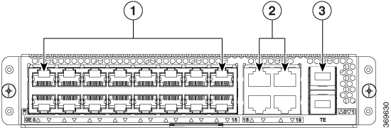
1 |
GE copper port |
3 |
1G/10G SFP/SFP+ port |
|
2 |
MultiGiagabitEthernet ports (2.5G) |
|
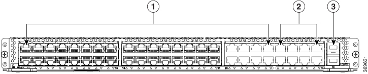
1 |
GE copper port |
3 |
1G/10G SFP/SFP+ port |
|
2 |
2.5G mGiG copper port |
To install a service module on your device, perform these steps:
|
Step 1 |
Read the Safety Warnings before you perform any module replacement. |
||
|
Step 2 |
For the module, remove the blank faceplate installed over the slot you intend to use. |
||
|
Step 3 |
For the module, remove both the blank faceplates and the divider installed over the slot you intend to use.
|
||
|
Step 4 |
With the service module, push the module into place until you feel the edge connector seat securely into the connector on the backplane. The module faceplate should contact to the chassis panel. |
||
|
Step 5 |
For the double-wide service module-C-SM-X-40P8M2X, keep the latches in open position before inserting the module. The latches assist to fully insert the module before securing the screws. |
||
|
Step 6 |
Using a number 1 Phillips or flat-blade screwdriver, tighten the captive mounting screws on the module faceplate. |
 Feedback