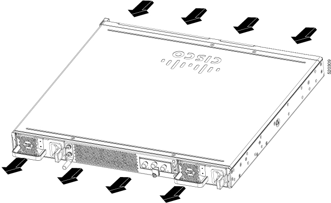
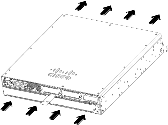
Chassis Views
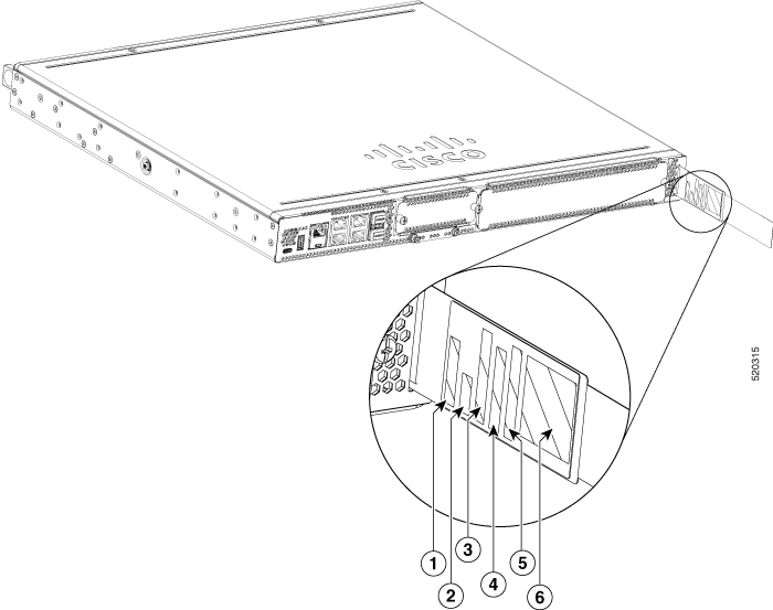
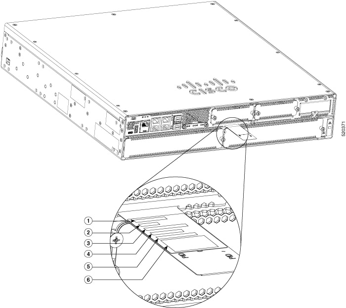
This section contains views of the Power Supply and I/O sides of the Cisco Catalyst 8300 Series Edge Platforms, showing the locations of power and signal interfaces, module slots, status indicators, and chassis identification labels:
Cisco Catalyst 8300 Series Edge Platforms are available in these models:
-
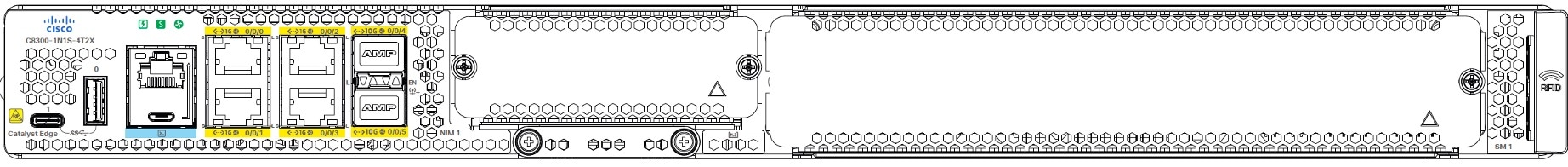
C8300-1N1S-4T2X
-
C8300-1N1S-6T
-
C8300-2N2S-4T2X
-
C8300-2N2S-6T
 Note |
N=Network Interface Modue, S=Services Module, and T=Gigabit Ethernet, X=Ten Gigabit |
|
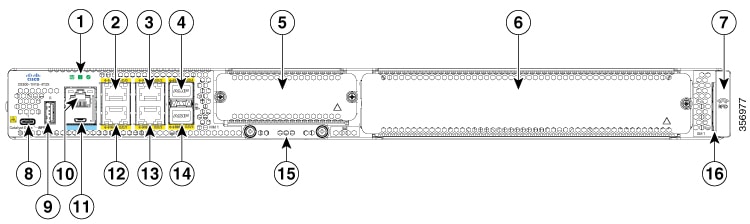
1 |
LED |
2 |
RJ-45 Gigabit Ethernet port (1G 0/0/0) |
|
3 |
RJ-45 Gigabit Ethernet port (1G 0/0/2) |
4 |
SFP+/10 Gigabit Ethernet port (10G 0/0/4) SFP/1 Gigabit Ethernet port (1G 0/0/4) |
|
5 |
NIM Slot1 |
6 |
SM Slot1 |
|
7 |
RFID (Optional) |
8 |
USB Type C (3.0) (USB 1) |
|
9 |
USB Type A (3.0) (USB 0) |
10 |
RJ-45 Console |
|
11 |
Micro-USB Console |
12 |
RJ-45 Gigabit Ethernet port (1G 0/0/1) |
|
13 |
RJ-45 Gigabit Ethernet port (1G 0/0/3) |
14 |
SFP+/10 Gigabit Ethernet port (10G 0/0/5) SFP/1 Gigabit Ethernet port (1G 0/0/5) |
|
15 |
M.2 USB/NVMe storage |
16 |
Device Label Tray |
|
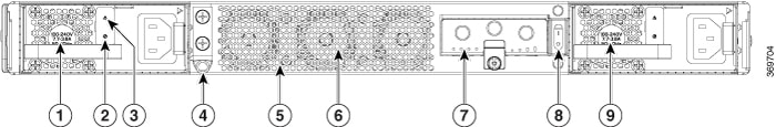
1 |
AC/DC power supply unit (PSU1) |
2 |
Power, Preset, OK, LED |
|
3 |
ALARM Fail LED |
4 |
Ground lug |
|
5 |
Fan tray vent |
6 |
3-Internal Fan tray |
|
7 |
PIM Slot 1 |
8 |
Power switch |
|
9 |
AC/DC Power Supply Unit (PSU0) |
|
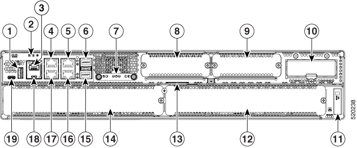
1 |
USB Type A (3.0) (USB 0) |
2 |
LED |
|
3 |
RJ-45 Console |
4 |
RJ-45 Gigabit Ethernet port (1G 0/0/0) |
|
5 |
RJ-45 Gigabit Ethernet port (1G 0/0/2) |
6 |
SFP+/10 Gigabit Ethernet port (10G 0/0/4) for C8300-2N2S-4T2X SFP/1 Gigabit Ethernet port (1G 0/0/4) for C8300-2N2S-6T |
|
7 |
M.2 USB/NVMe storage |
8 |
NIM Slot 1 |
|
9 |
NIM Slot 2 |
10 |
PIM Slot 1 |
|
11 |
RFID (Optional) |
12 |
SM Slot 2 |
|
13 |
Device label tray |
14 |
SM Slot 1 |
|
15 |
SFP+/10 Gigabit Ethernet port (10G 0/0/5) for C8300-2N2S-4T2X SFP/1 Gigabit Ethernet port (1G 0/0/5) for C8300-2N2S-6T |
16 |
RJ-45 Gigabit Ethernet port (1G 0/0/3) |
|
17 |
RJ-45 Gigabit Ethernet port (1G 0/0/1) |
18 |
Micro-USB Console |
|
19 |
USB Type C(3.0) (USB 1) |
|
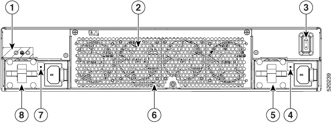
1 |
Ground Lug |
2 |
FRU Fan tray |
|
3 |
Power Switch |
4 |
PSU0 Power LED |
|
5 |
PSU0 |
6 |
POE Power Module 0/1, behind removable Fan tray |
|
7 |
PSU1 Power LED |
8 |
PSU1 |
For detailed information on LEDs, see the section on LED indicators.
Platform Summary
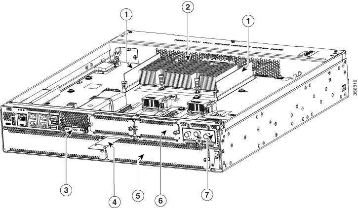
The figure below shows the internal view of Cisco Catalyst 8300 Series Edge Platforms with components and module locations.
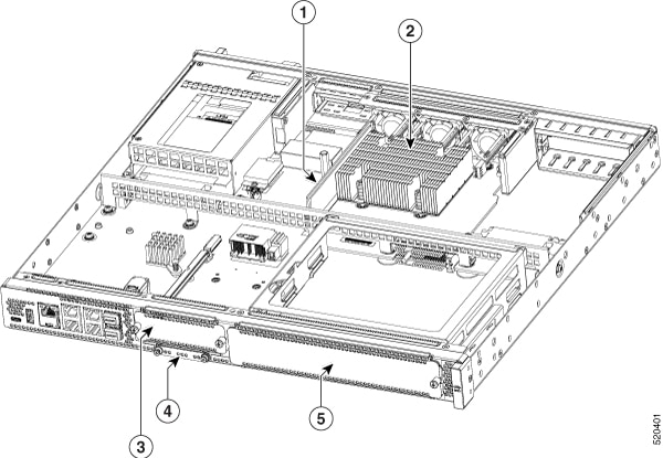
|
1 |
DIMM |
2 |
CPU |
|
3 |
NIM slot |
4 |
M.2 card slot |
|
5 |
SM |
|
1 |
DIMMs |
2 |
CPU |
|
3 |
M.2 Card slot |
4 |
Label tray |
|
5 |
SM |
6 |
NIM |
|
7 |
PIM |

 Feedback