Install Cisco Catalyst Network Interface Module

This section provides information before and during the installation of Cisco Catalyst Network Interface Modules (NIMs) on the Cisco Catalyst 8300 Series Edge Platforms.

Overview of the Network Interface Module

The Cisco Catalyst Network Interface Module (NIM), which has 10G WAN and 1xSFP+ 10G port is supported on Cisco Catalyst 8300 Series Edge Platforms.

For additional information, see the Cisco Catalyst 8300 Series Edge Platforms datasheet on cisco.com for a list of supported NIMs on the platforms.

Figure shows the front panel of the Catalyst Network Interface Module

Figure 1. Front Panel of Catalyst NIM

LED

Description

1

L/A (top)

Off: No link.

Green: Link established.

Blinking green: Packets being transmitted.

2

EN (top)

Off: The SFP is not present.

Green: The SFP is supported and no faults.

Amber: The SFP is not supported or is in a fault state.

3

EN (bottom)

Off: Default state when the module is powered on for the first time. This state is persistent until changed by the host software.

Green: The module is powered on and is functioning correctly.

Amber: The module has some failure.

Remove and Install Network Interface Modules

Keep the following tools and equipment while working with the Network Interface Modules (NIM)s:

  • Number 1 Phillips screwdriver or a small flat-blade screwdriver

  • ESD-preventive wrist strap

Remove the Network Interface Module

Step 1 Shut down the electrical power to the slot in the device, turn off the electrical power to the device. Leave the power cable plugged-in to channel ESD voltages to ground.

Step 2 Remove all network cables from the rear panel of the device. Using a number 1 Phillips screwdriver, loosen the captive screws on the network interface module.

Step 3 Slide the network interface module out.

Step 4 If you are not replacing the module, install a blank faceplate over the empty slot to ensure proper air flow.

Install the Cisco Catalyst Network Interface Modules

Step 1 Shut down the electrical power to the slot in the router by turning off the electrical power to the router. Leave the power cable plugged in to channel ESD voltages to ground.

Step 2 Remove all network cables from the rear panel of the device.

Step 3 Remove the blank faceplates installed over the network interface module slot that you intend to use.


Note


Save blank faceplates for future use.


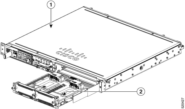
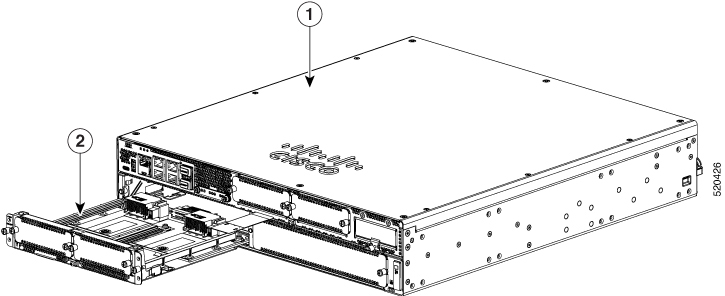
Step 4 Align the module with the guides in the chassis walls or slot divider and slide it gently into the NIM slot on the device.

Step 5 Push the module into place until you feel the edge connector seat securely into the connector on the router backplane. The module faceplate should contact the chassis rear panel.

Step 6 Using a number 1 Phillips screwdriver, tighten the captive screws on the network interface module.

Step 7 Connect the module to the network and re-enable the power to the slot in the device.

Remove and Install Network Interface Modules Adapter

This section provides information for before and during the installation of the Cisco Catalyst NIM adapter for two Cisco network interface modules (NIMs) on the Cisco Catalyst 8300 Series Edge Platforms.

Figure 2. Front Panel of Cisco Catalyst NIM Adapter

Description

1

LED: EN

Off: Device power is off, or the adapter has not yet started. (It may take several seconds for the adapter to start after the router is powered on.)

Green, solid: Powered on and functioning normally.

Amber, solid: Module has some type of failure.

2

NIM slots

Remove the Network Interface Module Adapter

Before You Begin

  • Read the safety warnings section before beginning this procedure.

  • The Cisco Catalyst NIM adapter is considered "hot swappable." Removing the adapter does not require powering off the device.

  • When preparing to remove the Cisco Catalyst NIM adapter, first remove any installed NIMs, and then remove the adapter.

Procedure

To remove the Cisco Catalyst NIM adapter from a service module (SM) slot on a Cisco Catalyst 8300 Series Edge Platforms:

Step 1 Locate the NIM adapter to be removed. Using a number 1 Phillips or flat-blade screwdriver, unscrew the captive mounting screws on the module faceplate.

Step 2 Pull the NIM adapter out of the chassis.

Step 3 Align the module with the guides in the chassis walls or slot divider and slide it gently into the NIM slot on the device.

Step 4 Place the NIM adapter in an antistatic bag to protect it from electrostatic discharge (ESD) damage.

Step 5 Install a blank faceplate over the empty slot to ensure proper air flow.

Install Network Interface Module Adapter

Before You Begin

  • Read the safety warnings section before beginning this procedure.

  • The Cisco Catalyst NIM adapter is considered 'hot swappable'. Installing the adapter does not require powering off the device.

  • Do not install network interface modules (NIMs) into the Cisco Catalyst NIM adapter before installing the adapter in the chassis.

  • When preparing to remove the Cisco Catalyst NIM adapter, first remove any installed NIMs, then remove the adapter.

Procedure

To install the Cisco Catalyst NIM adapter into a service module (SM) slot on a Cisco Catalyst 8300 Series Edge Platforms:

  1. Remove the blank faceplate installed over one of the device SM slots. The position of the slots depends on the platform's form factor: 1 rack unit (RU) or 2 RU, as shown below.


    Note


    Save blank faceplates for future use.


    Figure 3. Cisco Catalyst SM-NIM Adapter on C8300-1N1S-4T2X|6T
    Figure 4. Cisco Catalyst SM-NIM Adapter in C8300-2N2S-4T2X|6T

    Description

    1

    Chassis

    2

    Cisco C-SM-NIM adapter

  2. Align the Catalyst NIM adapter with the guides in the chassis walls or slot divider and slide it gently into a service module (SM) slot on the router.

  3. Push the Catalyst NIM adapter into place until you feel the edge connector seat securely into the connector on the router backplane. The faceplate should contact the chassis rear panel.

  4. Using a number 1 Phillips screwdriver, tighten the captive screws on the network interface module.

  5. Check the LED on the Catalyst NIM adapter and confirm proper operation.


    Note


    A solid green LED indicates that the Catalyst NIM adapter is correctly inserted. It may take several seconds for the adapter to start before the LED is solid green.


  6. (Optional) Install either one or two network interface modules into the Catalyst NIM adapter after it has been installed in the chassis. Follow the instructions for installing the NIM.

Install Network Interface Modules in the NIM Adapter

The Cisco Catalyst NIM adapter provides two network interface module (NIM) slots. To install a NIM into the adapter, follow the instructions for the NIM.


Note


  • Install the Cisco Catalyst NIM adapter into the router chassis before installing any NIMs into the adapter.

  • Before removing the Cisco Catalyst NIM adapter from the chassis, first remove any NIMs that have been installed into the adapter.