About Cisco 1000 Series Integrated Service Routers
The Cisco 1000 Series Integrated Services Routers are the next generation, IOS XE-based, multi core, branch routers. They are available in both fixed and modular form factors. The Cisco 1000 Series Integrated Services Routers is best suited for small and midsize businesses, enterprise branches, and as customer premises equipment in managed services environments.
|
Base Models |
Front Panel Switch Ports |
WAN Ports |
Console Port |
(Optional) POE |
(Optional) WLAN |
(Optional) LTE |
(Optional) DSL |
|---|---|---|---|---|---|---|---|
|
C111x-8P |
8 |
2 (1 Combo RJ-45/SFP + 1 RJ-45) |
Serial RJ-45, Micro USB |
4PoE/2PoE+ |
None |
4G LTE-Advanced (CAT6) with carrier aggregation |
G.FAST, VDSL2 and ADSL2/2+ |
|
C1111X-8P |
8 |
2 (1 Combo RJ-45/SFP + 1 RJ-45) |
Serial RJ-45, Micro USB |
4PoE/2PoE+ |
None |
None |
None |
|
C111x-4P |
4 |
2 (1 Combo RJ-45/SFP + 1 RJ-45) |
Serial RJ-45, Micro USB |
2 POE/1 POE+ |
802.11ac WAVE 2 |
4G LTE-Advanced (CAT6) with carrier aggregation |
VDSL2 and ADSL2/2+ |
|
C1101-4PLTEPWx |
4 |
1 RJ-45 |
Micro USB |
None |
802.11ac WAVE 2 (C1101-4PLTEPWx) |
4G pluggable LTE (CAT 4) and pluggable LTE Advanced (CAT 6) with carrier aggregation |
None |
|
C1101-4P |
4 |
1 RJ-45 |
Micro USB |
None |
None |
None |
None |
|
C1109-2PLTE |
2 |
1 RJ-45 |
Micro USB |
None |
None |
4G LTE (CAT 4) |
None |
|
C1109-4PLTE2P |
4 |
1 RJ45 |
Micro USB |
None |
802.11ac WAVE 2 (C1109-4PLTE2PWx) |
Dual pluggable modems - 4G pluggable LTE (CAT 4) and pluggable LTE Advanced (CAT 6) with carrier aggregation |
None |
|
C1121-4P |
4 |
2(1 Combo RJ45/SFP+1 RJ45 |
Micro USB |
2 POE/1 POE+ |
None |
None |
None |
|
C1121-4PLTEP |
4 |
2(1 Combo RJ45/SFP+1 RJ45 |
Micro USB |
2 POE/1 POE+ |
None |
4G Pluggable LTE (CAT 4) and pluggable LTE Advanced (CAT 6) with carrier aggregation |
None |
|
C11x1(X)-8P * |
8 |
2(1 Combo RJ45/SFP+1 RJ45 |
Micro USB |
4 POE/2 POE+ |
None |
None |
None |
|
C11x1(X)- 8PLTEP * |
8 |
2(1 Combo RJ45/SFP+1 RJ45 |
Micro USB |
4 POE/2 POE+ |
None |
4G Pluggable LTE (CAT 4) and pluggable LTE Advanced (CAT 6) with carrier aggregation |
VDSL2, ADSL2/2+, G.SHDSL |
|
C1121X-8PLTEPWx |
8 |
2(1 Combo RJ45/SFP+1 RJ45 |
Micro USB |
4 POE/2 POE+ |
802.11 AC WAVE 2 |
4G Pluggable LTE (CAT 4) and pluggable LTE Advanced (CAT 6) with carrier aggregation |
None |
|
C1131X-8PLTEPWx C1131-8PLTEPWx |
8 |
2x L3 Gigabit RJ45/SFP Combo |
Serial RJ45 |
4 POE/2 POE+ |
802.11 AX WiFi 6 |
5G Plugabble LTE |
None |
|
C1131X-8PWx C1131-8PWx |
8 |
2x L3 Gigabit RJ45/SFP Combo |
Serial RJ45 |
4 POE/2 POE+ |
802.11 AX WiFi 6 |
None |
None |
|
Pluggable Interface Modules |
Pluggable Interface Modules Technology |
|---|---|
|
P-LTE-GB |
CAT4 LTE Pluggable Europe SMS/GPS |
|
P-LTE-GB= |
CAT4 LTE Pluggable Europe SMS/GPS |
|
P-LTE-IN |
CAT4 LTE Pluggable India and China |
|
P-LTE-IN= |
CAT4 LTE Pluggable India and China |
|
P-LTE-JN |
CAT4 LTE Pluggable Japan |
|
P-LTE-JN= |
CAT4 LTE Pluggable Japan |
|
P-LTE-NA |
CAT4 LTE Pluggable for North America |
|
P-LTE-NA= |
CAT4 LTE Pluggable for North America |
|
P-LTE-US |
CAT4 LTE Pluggable for United States |
|
P-LTE-US= |
CAT4 LTE Pluggable for United States |
|
P-LTE-VZ |
CAT4 LTE Pluggable Verizon |
|
P-LTE-VZ= |
CAT4 LTE Pluggable Verizon |
|
P-LTEA-EA |
CAT6 LTE Advanced Pluggable for Europe and North America |
|
P-LTEA-EA= |
CAT6 LTE Advanced Pluggable for Europe and North America |
|
P-LTEA-LA |
CAT6 LTE Advanced Pluggable for APAC, LATAM, and ANZ |
|
P-LTEA-LA= |
CAT6 LTE Advanced Pluggable for APAC, LATAM, and ANZ |
|
P-LTEAP18-GL |
CAT6 LTE Advanced PRO Pluggable for ALL Global Regions |
|
P-LTEAP18-GL= |
CAT6 LTE Advanced PRO Pluggable for ALL Global Regions |
|
P-5GS6-GL |
5G Sub-6 GHz Pluggable Interface Module |
|
P-5GS6-R16SA-GL |
5G Sub-6 GHz Pluggable Interface Module |
|
P-LTEA7-NA |
CAT7 LTE Pluggable for North America |
|
P-LTEA7-JP |
CAT7 LTE Advanced PIM for Japan |
|
P-LTEA7-EAL |
CAT7 LTE Advanced PIM for EMEA, APAC, LATAM |
 Note |
P-5GS6-GL is supported on C8300, C8200, C8200L, and Cisco 1000 Series Integrated Service Routers. P-5GS6-GL is supported on Cisco 1000 Series Integrated Service Routers from the Cisco IOS XE 17.9.2 release. |
Note |
Base Models with an 'X' has 8GB of DRAM and Flash memory. Example: C1111X-8P The C1131 models have 4GB of DRAM and 8G flash memory. The C1131X models have 8GB of DRAM and 16G flash memory. For the C1131 series, only the Class A statements in the Trademark notice, which is available at the beginning of this guide, is valid. Base Models without an 'X' have 4GB of DRAM and Flash Memory. Example: C1111-8P For base model-C11x1X-8PLTEP, 'x' represents the CPU performance level. |
For more information on the features and specifications of Cisco 1000 Series Integrated Services Routers, refer to the Cisco 1000 Series Integrated Services Routers Solution Overview document and Cisco 1000 Series Integrated Services Routers datasheet.
Chassis Views
Note |
The compliance label is present at the bottom of the product. |
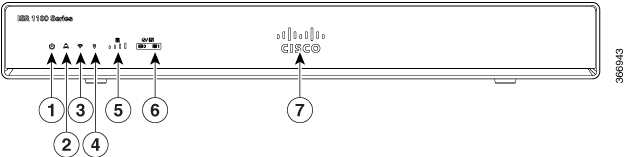
This section contains front and back panel views of the Cisco 1000 Series Integrated Services Routers showing locations of the power and signal interfaces, interface slots, status indicators, and chassis identification labels.
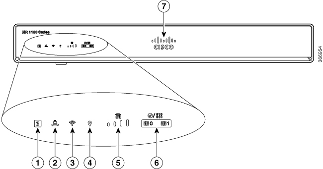
|
1 |
Status |
2 |
VPN |
|
3 |
Wi-Fi |
4 |
GPS |
|
5 |
LTE signal intensity |
6 |
LTE data/SIM |
|
7 |
Illuminated Cisco logo |
|
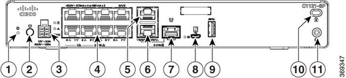
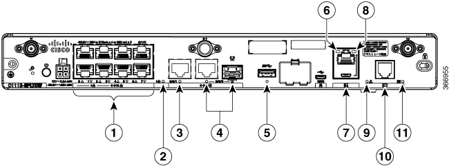
1 |
LTE antennas – main and diversity |
2 |
Ethernet switch |
|
3 |
GPS connection |
4 |
CLEI label |
|
5 |
Serial number |
6 |
Grounding |
|
7 |
Reset button |
8 |
Power switch |
|
9 |
4-pin power connector |
10 |
GE 0/0/1 |
|
11 |
GE 0/0/0 - RJ45 |
12 |
GE 0/0/0 - SFP |
|
13 |
USB3.0 |
14 |
Lower slot0 Upper slot1 |
|
15 |
LTE provisioning port |
16 |
RJ45/Micro USB console |
|
17 |
DSL |
18 |
Kensington lock slot |
|
19 |
Product Identification Number (PID) |
Note |
For more information on the Reset Button, refer to the Reset Overview section in the ISR 1000 Series Integrated Services Routers. |
|
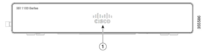
1 |
Non-illuminated Cisco logo |
|
1 |
Kensington lock slot |
2 |
Grounding |
|
3 |
Power switch |
4 |
4-pin power connector |
|
5 |
Reset button |
6 |
LAN: 0-4 |
|
7 |
GE WAN |
8 |
Micro USB console |
|
9 |
USB3.0 |
|
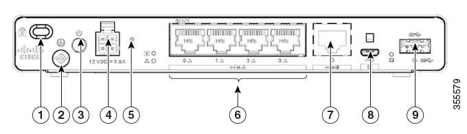
1 |
Non-illuminated Cisco logo |
|
1 |
Power switch |
2 |
4-pin power connector |
|
3 |
Reset button |
4 |
LAN:0-4 |
|
5 |
GE WAN |
6 |
Micro-USB console port |
|
7 |
Pluggable |
8 |
Grounding |
|
9 |
Kensington lock slot |
|
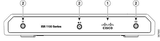
1 |
Non-illuminated Cisco logo |
| 2 |
Main and diversity antenna |
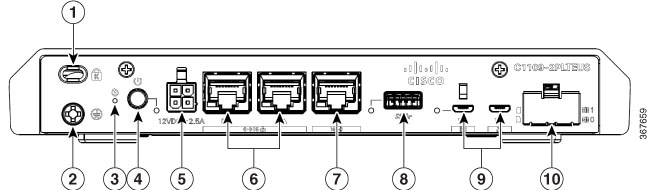
|
1 |
Kensington lock slot |
2 |
Grounding |
|
3 |
Reset button |
4 |
Power switch |
|
5 |
4-pin power connector |
6 |
LAN: 0 & 1 |
|
7 |
GE WAN |
8 |
Micro-USB console port |
|
9 |
USB 3.0 |
10 |
Micro-SIM slots 0 and 1 |
|
1 |
Grounding |
2 |
Power switch |
|
3 |
Reset button |
4 |
4-pin power connector |
|
5 |
LAN:0-4 |
6 |
GE WAN |
|
7 |
USB 3.0 |
8 |
Micro-USB console port |
|
9 |
LTE antenna |
10 |
Kensington lock slot |
|
1 |
Non-illuminated Cisco logo |
|
1 |
Reset button |
2 |
Power switch |
|
3 |
4-pin power connector |
4 |
Ethernet switch |
|
5 |
RJ-45 stacked connector |
6 |
GE WAN 0/0/0 -RJ45 |
|
7 |
GE WAN 0/0/0 -SFP |
8 |
Micro-USB console |
|
9 |
USB 3.0 |
10 |
Kensington lock slot |
|
11 |
Grounding |
|
1 |
Reset button |
2 |
Power switch |
|
3 |
4-pin power connector |
4 |
Ethernet switch |
|
5 |
GE 0/0/1 |
6 |
GE WAN 0/0/0 -RJ45 |
|
7 |
GE WAN 0/0/0 -SFP |
8 |
Micro-USB console |
|
9 |
USB 3.0 |
10 |
Pluggable |
|
11 |
Kensington lock slot |
12 |
Grounding |
|
1 |
Non-illuminated Cisco logo |
|
1 |
Reset button |
2 |
Power switch |
|
3 |
4-pin power connector |
4 |
Ethernet switch |
|
5 |
RJ-45 |
6 |
GE WAN 0/0/0 -RJ45 |
|
7 |
GE WAN 0/0/0 -SFP |
8 |
Micro-USB console |
|
9 |
USB 3.0 |
10 |
Kensington lock slot |
|
11 |
Grounding |
|
1 |
Reset button |
2 |
Power switch |
|
3 |
4-pin power connector |
4 |
Ethernet switch |
|
5 |
GE 0/0/1 |
6 |
GE WAN 0/0/0 -RJ45 |
|
7 |
GE WAN 0/0/0 -SFP |
8 |
Micro-USB console |
|
9 |
USB 3.0 |
10 |
Pluggable |
|
11 |
Kensington lock slot |
12 |
Grounding |
|
1 |
Non-illuminated Cisco logo |
|
1 |
Reset button |
2 |
Power switch |
|
3 |
4-pin power connector |
4 |
Ethernet switch |
|
5 |
Wi-Fi status |
6 |
GE 0/0/1 |
|
7 |
GE WAN 0/0/0 -RJ45 |
8 |
GE WAN 0/0/0 -SFP |
|
9 |
Micro-USB console |
10 |
USB 3.0 |
|
11 |
Pluggable |
12 |
Kensington lock slot |
|
13 |
Grounding |
|
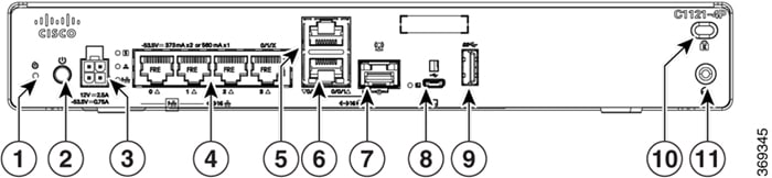
1 |
Non-illuminated Cisco logo |
|
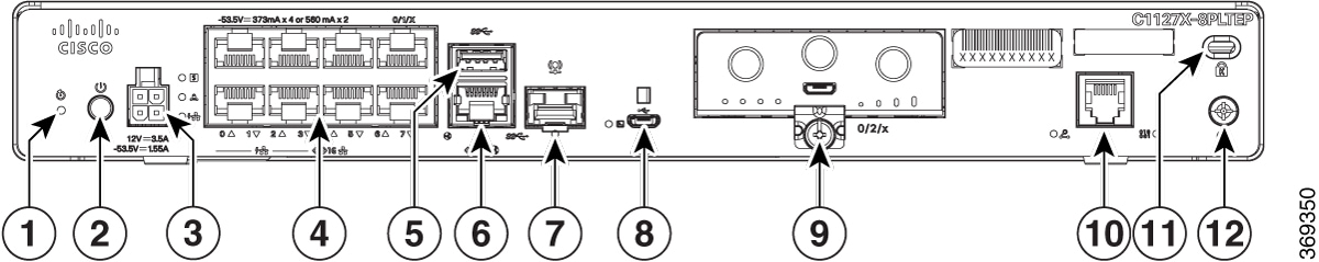
1 |
Reset button |
2 |
Power switch |
|
3 |
4-pin power connector |
4 |
Ethernet switch |
|
5 |
RJ-45 |
6 |
GE WAN 0/0/0 -RJ45 |
|
7 |
GE WAN 0/0/0 -SFP |
8 |
Micro-USB console |
|
9 |
Pluggable |
10 |
DSL |
|
11 |
Kensington lock slot |
12 |
Grounding |
|
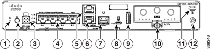
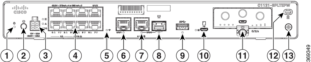
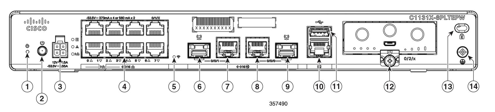
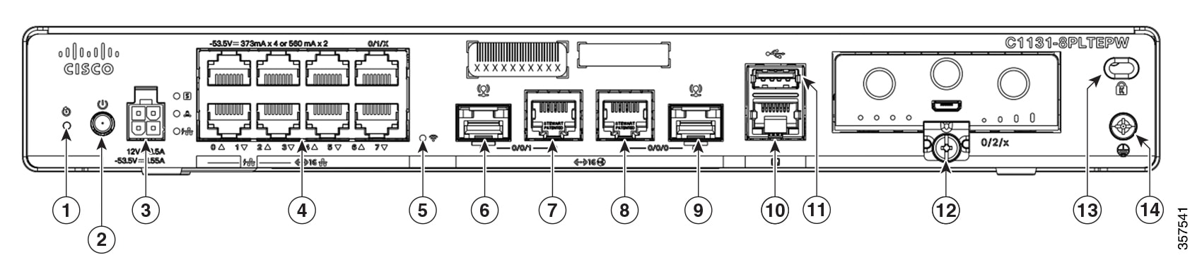
1 |
Non-illuminated Cisco logo |
|
1 |
Reset button |
2 |
Power switch |
|
3 |
4-pin power connector |
4 |
Ethernet switch |
|
5 |
USB 3.0 |
6 |
GE WAN 0/0/0 -RJ45 |
|
7 |
GE WAN 0/0/0 -SFP |
8 |
Micro-USB console |
|
9 |
Pluggable |
10 |
Symmetrical High-speed Digital Subscriber Lines (SHDSL) |
|
11 |
Kensington lock slot |
12 |
Grounding |
|
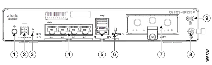
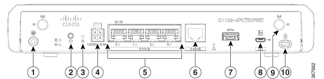
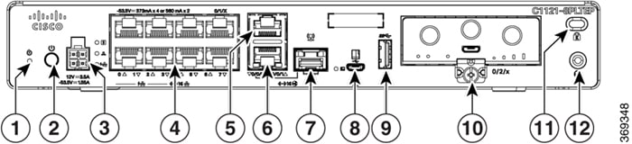
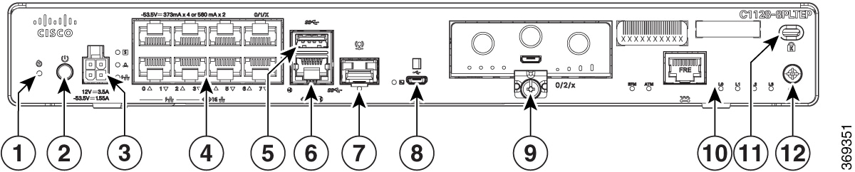
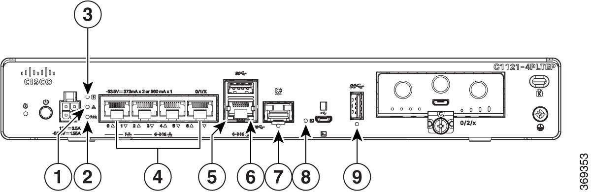
1 |
Non-illuminated Cisco logo |
|
1 |
Reset button |
2 |
Power switch |
|
3 |
4-pin power connector |
4 |
Ethernet switch |
|
5 |
Wi-Fi status |
6 |
GE WAN 0/0/1 - SFP |
|
7 |
GE WAN 0/0/1 -RJ45 |
8 |
GE WAN 0/0/0 -RJ45 |
|
9 |
GE WAN 0/0/0 - SFP |
10 |
Console |
|
11 |
USB 2.0 |
12 |
Pluggable |
|
13 |
Kensington lock slot |
14 |
Grounding |
LED Indicators
The following figures and table summarizes the LED indicators that are located in the bezel or chassis of the C111x series.
|
1 |
Status |
2 |
VPN |
|
3 |
WLAN |
4 |
GPS |
|
5 |
LTE RSSI/mode |
6 |
LTE data/SIM |
|
7 |
Cisco logo |
|
1 |
GE WAN ports: 0-7 (0, 2, 4, 6 at the top and 1, 3, 5, 7 at the bottom) |
2 |
PoE LED |
|
3 |
GE1 LED |
4 |
GE0 LED |
|
5 |
USB LED |
6 |
RJ-45 console LED |
|
7 |
USB console |
8 |
Micro USB console LED |
|
9 |
CD LED |
10 |
DATA LED |
|
1 |
VPN |
2 |
PoE LED |
|
3 |
Status |
4 |
Ethernet switch ports 0-3 |
|
5 |
GE 0/0/0 RJ45 LED |
6 |
GE 0/0/1 LED |
|
7 |
GE 0/0/0 RJ45 LED |
8 |
Micro USB console LED |
|
9 |
USB LED |
|
1 |
VPN |
2 |
PoE LED |
|
3 |
Status |
4 |
Ethernet switch ports 0-3 |
|
5 |
GE 0/0/0 RJ45 LED |
6 |
GE 0/0/1 LED |
|
7 |
GE 0/0/0 RJ45 LED |
8 |
Micro USB console LED |
|
9 |
USB LED |
|
1 |
VPN |
2 |
PoE LED |
|
3 |
Status |
4 |
Ethernet switch ports 0-7 (0, 2, 4, 6 at the top and 1, 3, 5, 7 at the bottom) |
|
5 |
GE 0/0/0 RJ45 LED |
6 |
GE 0/0/1 LED |
|
7 |
GE 0/0/0 RJ45 LED |
8 |
Micro USB console LED |
|
9 |
USB LED |
|
1 |
VPN |
2 |
PoE LED |
|
3 |
Status |
4 |
Ethernet Switch Ports 0-7 (0, 2, 4, 6 at the top and 1, 3, 5, 7 at the bottom) |
|
5 |
Wi-Fi |
6 |
GE 0/0/0 RJ45 LED |
|
7 |
GE 0/0/1 LED |
8 |
GE 0/0/0 SFP LED |
|
9 |
USB LED |
10 |
Micro USB console LED |
|
1 |
VPN |
2 |
PoE LED |
|
3 |
Status |
4 |
Ethernet Switch Ports 0-7 (0, 2, 4, 6 at the top and 1, 3, 5, 7 at the bottom) |
|
5 |
GE 0/0/0 RJ45 LED |
6 |
USB5 LED |
|
7 |
GE 0/0/0 SFP LED |
8 |
Micro USB console LED |
|
9 |
CD LED |

|
1 |
VPN |
2 |
PoE LED |
|
3 |
Status |
4 |
Ethernet switch ports 0-7 (0, 2, 4, 6 at the top and 1, 3, 5, 7 at the bottom) |
|
5 |
Wi-Fi |
6 |
GE 0/0/1 SFP LED |
|
7 |
GE 0/0/1 RJ45 LED |
8 |
GE 0/0/0 RJ45 LED |
|
9 |
GE 0/0/0 SFP LED |
10 |
USB LED |
|
11 |
Console LED |
The following table summarizes the LED indicators that are located in the bezel or chassis of the C111x series.
|
Port |
LED Color |
Description |
Control Source |
|---|---|---|---|
|
Cisco logo |
Blue |
Illuminated Cisco logo. Indicates that router is powered on. |
Bezel side |
|
Status (System status) |
Green and Amber |
Steady green - System is operating normally. |
Bezel side. All models. |
|
Off—System is not out of reset mode or BIOS image is not loadable. |
|||
|
Blinking Amber — BIOS/ROMmon is booting. |
|||
|
Steady Amber — BIOS/ROMmon has completed booting, and the system is at the ROMmon prompt or booting the platform software. |
|||
|
VPN OK |
Green |
Off— No tunnel. |
Bezel side |
|
Steady On— At least one tunnel is up. |
|||
|
LTE RSSI/mode |
Green and Amber |
No LEDs On—No service |
Bezel side |
|
1 LED On— RSSI is under -100dBm. |
|||
|
2 LEDs On— Low RSSI, -99dbm <> -90dBm. |
|||
|
3 LEDs On— Medium RSSI -89dBm <> -70dBm. |
|||
|
4 LEDs On— High RSSI, > -69dBm. |
|||
|
Green— LTE |
|||
|
Amber— 3G |
|||
|
GPS |
Green |
Off: GPS not configured |
Bezel side |
|
On: GPS configured |
|||
|
Blink: GPS acquiring |
|||
|
WLAN |
Green, Red, and Amber |
Green— Normal operating condition with at least one wireless client association. |
Bezel side |
|
Red—Ethernet link is not operational or ethernet failure. |
|||
|
Amber—Software upgrade is in progress. |
|||
|
Ethernet switch GE LAN ports, non-PoE |
Green |
Off— No link |
I/O side |
|
Steady On— Link |
|||
|
Blink— TXD/RXD data |
|||
|
Ethernet switch GE LAN ports, with PoE |
Green and Amber |
Off— No link, no device powered, PD denied power, power delivery fault PoE administratively disabled. Green steady on— link; if PoE device, power is enabled. Green Blink— TXD/RXD data Amber - PoE fault |
I/O side |
|
PoE OK |
Green |
Green steady on— -53.5V PoE power supply connected and all powered port operating normally. |
I/O side |
|
Off — No -53.5V PoE power supply connected to router. |
|||
|
GE WAN ports |
Green |
Off— No link |
I/O side |
|
Steady on— link |
|||
|
Blink— TXD/RXD data |
|||
|
DSL CD |
Green |
Off— Shut |
I/O side |
|
Green blink— Training, or no shut and cable disconnected. |
|||
|
Green steady on— Trained |
|||
|
DSL data |
Green |
Off— No data activity |
I/O side |
|
Green blink— TX/RX Data |
|||
|
Console |
Green |
Green on— console enabled. |
I/O side |
|
USB console |
Green |
Off— No USB device discovered. |
I/O side |
|
On— USB device discovered. |
|||
|
USB |
Green |
Off: No USB device discovered. |
I/O side |
|
On: USB device discovered. |
|
LED |
Color |
Description |
Control Source |
|---|---|---|---|
|
Power |
Green+Amber |
System power status Off: No power Green steady on: Normal operation Green blink: Boot up phase or in ROM monitor mode Amber steady on or blink: Some issues with the system. |
I/O |
|
VPN OK |
Green |
VPN Status Off: No tunnel Steady on:At least one tunnel is up |
I/O |
|
Ethernet switch GE LAN ports |
Green |
Link activity Off: No link Steady on: Link Blink: TXD/RXD Data |
I/O |
|
GE WAN ports |
Green |
Link activity Off: No link Steady on: Link Blink: TXD/RXD Data |
I/O |
|
LTE DATA/SIM (C1101-4PLTEPWz C1101-4PLTEP/C1101-4PLTEPWx) |
Green and Amber |
Single LTE modem (one modem with SIM switch-over capability) Off: Modem not up or modem up and no SIM Amber steady on: Modem up, SIM installed but not active. Green Blink: LTE data activity. |
Bezel side |
|
WLAN |
3-color LED: Green, Red and Amber (C1101-4PLTEPWx) 3-color LED: Green, Blue and Red (C1131(X)-8PWx, C1131(X)-8PLTEPWx) For more information on the LED status, see the LED Status Indications. |
WLAN functions |
I/O |
|
USB console |
Green |
USB console status OFF: USB console not active ON: USB console active |
I/O |
|
USB 3.0 |
Green |
USB 3.0 status OFF: No USB device discovered ON: USB device discovered USB activity |
I/O |
Reset Button
The actuation of the Reset button is only recognized during ROMmon boot, that is, as the router comes to the ROMmon prompt.
The Reset button does not require much force to be pressed. The Reset button should be pressed only with a small implement such as the tip of a pen or a paper clip. When the Reset button is pressed at startup, the system LED turns green.
For more information, see the "Reset Overview" section of the Cisco 1100 Software Configuration Guide.
Power Supply
C111x, C1121x, and C1131 Series Integrated Services Routers support PoE and PoE+ power to endpoints. The product power specifications are as follows:
-
AC input voltage: Universal 100 to 240 VAC
-
Frequency: 50 to 60 Hz
-
Maximum output power: Up to 66W for non-PoE supply and upto 150W for PoE supply
-
Optional PoE and PoE+
-
Output voltage: +12VDC for system power and -53.5VDC for PoE power
Slots and Interfaces
About Slots, Subslots, and Port Numbering
The Cisco 1100 series designates its interfaces using a 3-tuple notation that lists the slot, sub slot and port in the format slot/sub-slot/port. The slot number is reserved for the mother board, which is "0". Each interface type is allocated a sub slot and the port number is a unique port on the interface.
|
Subslot |
Interface Type |
|---|---|
|
0 |
Ethernet LAN |
|
1 |
Ethernet WAN |
|
2 |
LTE |
|
3 |
DSL |
|
4 |
Wi-Fi |
Specifications of Cisco 1000 Series Integrated Services Routers
For specifications on the Cisco 1000 Series Integrated Services Routers, refer to the Cisco 1100 Series ISR Specifications document.
 Feedback