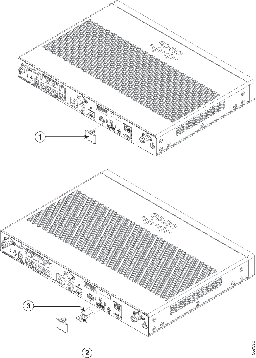
Replace the Chassis Covers for C111X and C1111x
 Warning |
Only trained and qualified personnel should be allowed to install, replace or service this equipment. Statement 1030 |
Cisco 1000 Series Integrated Services Routers have removable covers. Do not run the routers with the cover off. Doing so can cause the router to overheat very quickly.
Use a number-2 Phillips screw driver to perform the following tasks.
Remove the Cover
|
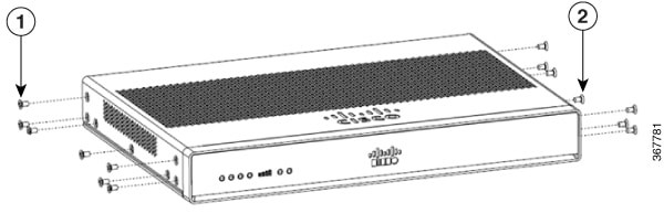
1 and 2 |
Remove the 14 screws from either side of the cover. |
Procedure
|
Step 1 |
Read the Safety Warnings and disconnect the power supply before you perform any module replacement. |
|
Step 2 |
Confirm the router is turned off and disconnected from the power supply. |
|
Step 3 |
Disconnect all port cables connected to the router. Ensure that you do not work on the router with cables still attached to the router in the event of lightning or surges. |
|
Step 4 |
Place the chassis on a flat surface. |
|
Step 5 |
Remove the 14 cover screws on the two sides of the router cover. See figure. |
|
Step 6 |
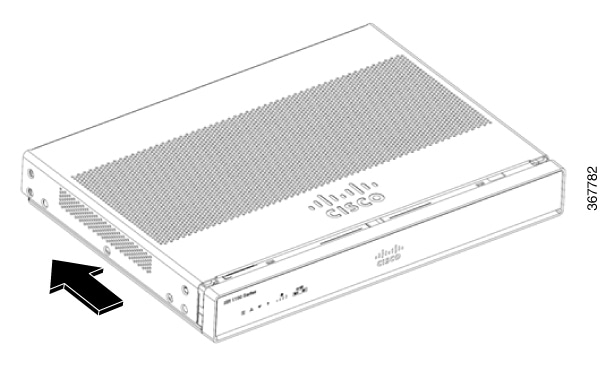
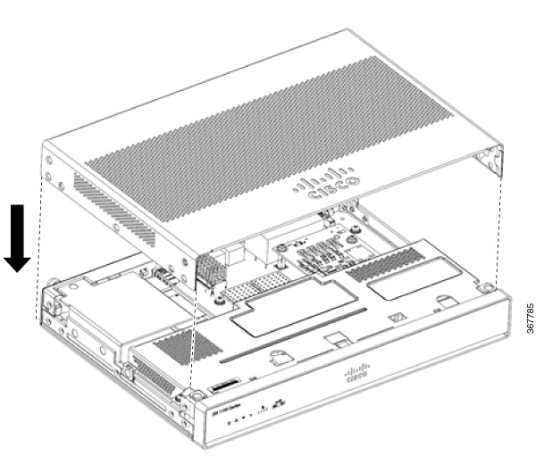
Slide the cover from bezel side to I/O side until it stops. |
|
Step 7 |
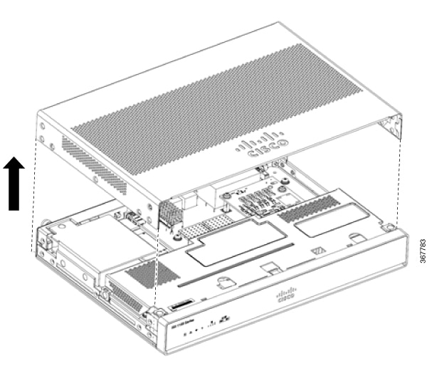
Pull the cover vertically to disengage from the chassis. |
Replace the Cover
Warning |
The covers are an integral part of the safety design of the product. Do not operate the unit without the covers installed. Statement 1077. |
|
1 and 2 |
Replace the 14 screws on either side of the cover. |
Procedure
|
Step 1 |
Read the Safety Warnings and disconnect the power supply before you perform any module replacement. |
|
Step 2 |
Confirm the router is turned off and disconnected from the power supply. |
|
Step 3 |
Disconnect all port cables connected to the router. Ensure that you do not work on the router with cables still attached to the router in the event of lightning or surges. |
|
Step 4 |
Place the chassis on a flat surface. |
|
Step 5 |
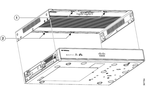
Align hooks on the cover to slots on the chassis base and lower the cover onto chassis base. |
|
Step 6 |
Slide the cover from the I/O side to the bezel side |
|
Step 7 |
Install the fourteen screws on both sides of the chassis. Torque to 6-8 in-lbs. |


 Feedback