Understanding Remote Node Management Using GCC

The remote node management feature allows you to remotely manage NCS 1004 nodes over the General Communication Channel (GCC) interface. The remote nodes that are not connected to the management network over the Ethernet interface can be managed over the GCC interface. This feature supports remote management of up to eight nodes in hub topology and up to two nodes in linear topology.

Figure 1. Remote Node Management in Linear Topology
Remote Node Management in Linear Topology

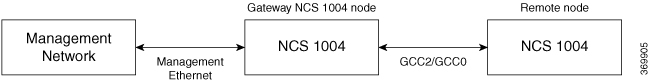
The remote nodes can be dynamically discovered over the GCC interface using OSPF. The connectivity to the management network can be achieved using OSPF and static routes.


Note


The GCC2 and GCC0 interfaces are supported in NCS 1004. The GCC0 interface is supported on the Coherent DSP controller whereas the GCC2 interface is supported on the ODU controller.


Note


The GCC0 and GCC2 interfaces are supported in Muxponder and Muxponder slice modes. Only the GCC0 interface is supported in the Regeneration (Regen) mode.


Remote Node Management on OTN-XP Card

Table 1. Feature History

Feature Name

Release Information

Feature Description

GCC Support for OTN-XP Card

Cisco IOS XR Release 7.3.2

The node supports a maximum of 48 GCC (GCC0 and GCC1) channels for each OTN-XP card.

From R7.2.1 onwards, the OTN-XP card provides OTU interface that supports communication channels between adjacent network elements or nodes using GCC bytes in the OTN header. Remote node management is supported over the GCC interface.

From R7.2.1 onwards, the node supports GCC0 on the corresponding OTU2, OTU2e, and OTU4 interfaces. The node (Cisco FPGA) supports a maximum of 22 GCC channels for each card.


Note


The GCC0 and GCC1 interfaces are supported on OTN-XP card and GCC2 interface is not supported.


From R7.3.1 onwards, the node supports GCC0 on the corresponding OTU2, OTU2e, OTU4, and Coherent DSP interfaces, and GCC1 on OTN ODU controller (ODU2, ODU2E, ODU4, and ODUCn).

From R7.3.2 onwards, the node (Cisco FPGA) supports a maximum of 48 GCC (GCC0 and GCC1) channels for each card.

Limitations

  • gRPC is not supported over the GCC interface. Therefore, Open Config and streaming telemetry are not supported over the GCC interface.

  • Only the Tx and Rx packet count information are available in GCC statistics.

  • The devices can be remotely managed over the GCC interface only when they are connected to the management network through GCC. Therefore, initial provisioning and bringing up of the GCC interface must be performed either through the console or management Ethernet interface.

  • These headless or high availability events at the intermediate nodes may affect remote node management of subsequent nodes:

    • Reload of the route processor

    • Reload of IOS XR

    • Restart of the driver process

  • IP fragmentation is not supported on GCC interface for the SCP protocol. As a workaround, you can apply any of the following configurations to limit the maximum packet size below the fragmentation limit (1454 bytes):

    • Use the tcp mss <maximum segment size> command (for example, tcp mss 1200 ) in the global configuration mode. The maximum segment limit is applied to all interfaces.

    • Use the ipv4 mtu <MTU size> command in the interface configuration mode. The MTU size is applied only to the specified interface.

  • The Coherent DSP controller supports the GCC0 interface on the QXP card.

  • The GCC0 speed on the QXP card is 7.7 Mbps.

Supported Protocols

The following protocols are supported over the GCC interface.

  • PING

  • SSH

  • TELNET

  • SCP

  • TFTP

  • FTP

  • SFTP

  • HTTP

  • HTTPS

  • OSPF

Enable the GCC Interface

Enable the GCC Interface on 1.2T Card

To enable the GCC2 interface for the 1.2T line card, use the following commands:


configure
controller odu4 R/S/I/P/L
gcc2
commit
exit

To enable the GCC0 interface for the 1.2T line card, use the following commands:


configure
controller CoherentDSP R/S/I/P
gcc0
commit
exit

Enable the GCC Interface on OTN-XP Card

To enable the GCC0 interface for the OTN-XP card, use the following commands:


RP/0/RP0/CPU0:ios#configure
RP/0/RP0/CPU0:ios(config)#controller {otu2 | otu2e | otu4} R/S/I/P/L
RP/0/RP0/CPU0:ios(config-otu)#gcc0
RP/0/RP0/CPU0:ios(config-otu)#commit
RP/0/RP0/CPU0:ios(config-otu)#exit

The following example displays how to enable the GCC0 interface for the OTN-XP card on OTU2 controller.


RP/0/RP0/CPU0:ios#configure
RP/0/RP0/CPU0:ios(config)#controller otu2 0/0/0/4/1
RP/0/RP0/CPU0:ios(config-otu2)#gcc0
RP/0/RP0/CPU0:ios(config-otu2)#commit
RP/0/RP0/CPU0:ios(config-otu2)#exit

To enable the GCC1 interface for the OTN-XP card, use the following commands:


RP/0/RP0/CPU0:ios#configure
RP/0/RP0/CPU0:ios(config)#controller {odu2 | odu2e | odu4 | oducn} R/S/I/P/L
RP/0/RP0/CPU0:ios(config-odu)#gcc1
RP/0/RP0/CPU0:ios(config-odu)#commit
RP/0/RP0/CPU0:ios(config-odu)#exit

The following example displays how to enable the GCC1 interface for the OTN-XP card on ODU2 controller.


RP/0/RP0/CPU0:ios#configure
RP/0/RP0/CPU0:ios(config)#controller odu2 0/0/0/4/1
RP/0/RP0/CPU0:ios(config-odu2)#gcc1
RP/0/RP0/CPU0:ios(config-odu2)#commit
RP/0/RP0/CPU0:ios(config-odu2)#exit

Configure the GCC Interface

Configure the GCC Interface on 1.2T Card

To configure the GCC2 interface using the static IP address for the 1.2T card, use the following commands:

configure

interface gcc2 R/S/I/P/L

ipv4 address ipv4-address

commit

exit

To configure the GCC0 interface using the static IP address for the 1.2T card, use the following commands:

configure

interface gcc0 R/S/I/P

ipv4 address ipv4-address

commit

exit

Configure the GCC Interface on OTN-XP Card

To configure the GCC0 interface on OTN-XP card, use the following commands:

configure

interface gcc0 R/S/I/P

ipv4 address ipv4-address net-mask

commit

exit

To configure the GCC1 interface on OTN-XP card, use the following commands:

configure

interface gcc1 R/S/I/P

ipv4 address ipv4-address net-mask

commit

exit

Examples

The following sample displays how to configure the GCC2 interface using the static IP address on 1.2T card:


RP/0/RP0/CPU0:ios#configure
RP/0/RP0/CPU0:ios(config)#interface gcc2 0/1/0/0/1
RP/0/RP0/CPU0:ios(config-if)#ipv4 address 198.51.100.244 255.255.255.0
RP/0/RP0/CPU0:ios(config-if)#commit
RP/0/RP0/CPU0:ios(config-if)#exit
RP/0/RP0/CPU0:ios(config)#exit
RP/0/RP0/CPU0:ios#show run interface gcc2 0/1/0/0/1
interface GCC20/1/0/0/1
 ipv4 address 10.1.1.1 255.255.255.0
!

The following sample displays how to configure the GCC2 interface using the loopback IP address on 1.2T card.


RP/0/RP0/CPU0:ios#configure
RP/0/RP0/CPU0:R2(config)#interface gcc2 0/1/0/0/1
RP/0/RP0/CPU0:R2(config-if)#ipv4 unnumbered loopback 0
RP/0/RP0/CPU0:ios(config-if)#exit
RP/0/RP0/CPU0:ios(config)#exit

The following sample checks the status of GCC2 interface.

RP/0/RP0/CPU0:ios#show ipv4 interface brief
Wed Sep 22 17:10:04.190 IST

Interface                      IP-Address         Status          Protocol Vrf-Name
GCC20/0/0/0/1                  198.51.100.234        Up              Up       default 
GCC20/3/0/1/3                  198.51.100.244        Up              Up       default 
Loopback0                      198.51.100.224        Up              Up       default

The following sample displays how to configure the GCC0 interface using the static IP address on 1.2T or OTN-XP card.


RP/0/RP0/CPU0:ios#configure
RP/0/RP0/CPU0:ios(config)#interface gcc0 0/1/0/0
P/0/RP0/CPU0:ios(config-if)#ipv4 address 198.51.100.244 255.255.255.0
RP/0/RP0/CPU0:ios(config-if)#commit
RP/0/RP0/CPU0:ios(config-if)#exit
RP/0/RP0/CPU0:ios(config)#exit
RP/0/RP0/CPU0:ios#show run interface gcc0 0/1/0/0
interface GCC00/1/0/0
 ipv4 address 198.51.100.244 255.255.255.0
!

The following sample displays how to configure the GCC0 interface using the loopback IP address on 1.2T or OTN-XP card.


RP/0/RP0/CPU0:ios#configure
RP/0/RP0/CPU0:R2(config)#interface gcc0 0/1/0/0
RP/0/RP0/CPU0:R2(config-if)#ipv4 unnumbered loopback 0
RP/0/RP0/CPU0:ios(config-if)#exit
RP/0/RP0/CPU0:ios(config)#exit

Note


The following configuration is required from R25.4.1 after configuring the GCC interface.

linux networking
vrf default
address-family ipv4
default-route software-forwarding
source-hint management-route interface MgmtEth0/RP0/CPU0/0
source-hint default-route interface MgmtEth0/RP0/CPU0/0

Configure Static Routes Over the GCC Interface

To configure the static routes over the GCC interface, use the following commands:

configure

router static address-family ipv4 unicast 0.0.0.0/0 default-gateway

exit

Examples


RP/0/RP0/CPU0:ios#configure
RP/0/RP0/CPU0:ios(config)#router static address-family ipv4 unicast 0.0.0.0/0 10.105.57.1
RP/0/RP0/CPU0:ios(config)#exit

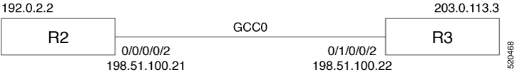
Configure OSPF Routes Over the GCC Interface

To configure OSPF routes over the GCC interface, use the following commands:

configure

router ospf process-id

router-id ip-address

area area-id

interface type R/S/I/P/L

exit

Examples

The following is a sample to configure OSPF routes over the GCC interface.

Gateway Node:


configure
router ospf 1
router-id 192.0.2.89                                                                                                  
 area 0                                                                                                        
  interface Loopback0                                                                                          
  !                                                                                                            
  interface MgmtEth0/RP0/CPU0/1                                                                                
  !                                                                                                            
  interface GCC20/0/0/0/1                                                                                      
  !                                                                                                            
  interface GCC20/0/0/0/2

Remote Node:


configure
router ospf 1  
router-id 192.0.2.92
redistribute connected                                                                                             
 area 0                                                                                                        
  interface Loopback0                                                                                          
  !                                                                                                            
  interface GCC20/0/0/0/1                                                                                      
  !                                                                                                            
  interface GCC20/0/0/0/2

iBGP Support Using GCC

The Internal BGP (iBGP) support over GCC allows external devices to exchange BGP routes through management interfaces of NCS1004 system. The NCS 1004 device advertises local networks through BGP and manages these networks using path learnt through BGP. With the iBGP route information, the NCS 1004 devices establish iBGP sessions over GCC to exchange BGP routes.

You can configure VPN routing and forwarding (VRF) on the GCC management interfaces (port 0 and port 1) of the NCS 1004 device. The VRF enables traffic isolation between the management ports (port 0 and port 1).

The GCC2 and GCC0 interfaces are supported in NCS 1004 for 1.2 T line card.

Restrictions for iBGP Support Using GCC

  • IP fragmentation is not supported on the GCC interface.

  • The BGP configuration over Open Config (OC) is not supported.


Note


The limitations of Remote Node Management Using GCC are applicable for iBGP Support Using GCC. For more information, see Limitations of Remote Node Management.


Enabling the GCC Interface

To enable the GCC2 interface, use the following commands:

configure
controller odu4 R/S/I/P/L
gcc2
commit
exit

To enable the GCC0 interface, use the following commands:

configure
controller CoherentDSP R/S/I/P
gcc0
commit
exit

Configuring the Management Interface

To configure the management Ethernet interface with VRF, use the following commands:


RP/0/RP0/CPU0:ios#configure
RP/0/RP0/CPU0:ios#interface MgmtEth0/RP0/CPU0/1
RP/0/RP0/CPU0:ios(config-if)#vrf transport-vrf
RP/0/RP0/CPU0:ios(config-if)#ipv4 address ipv4-address
RP/0/RP0/CPU0:ios(config-if)#commit
RP/0/RP0/CPU0:ios(config-if)#exit

The following example displays how to configure the management Ethernet interface with VRF.


RP/0/RP0/CPU0:ios#configure
RP/0/RP0/CPU0:ios#interface MgmtEth0/RP0/CPU0/1
RP/0/RP0/CPU0:ios(config-if)#vrf transport-vrf
RP/0/RP0/CPU0:ios(config-if)#ipv4 address 192.0.2.1 255.255.255.255
RP/0/RP0/CPU0:ios(config-if)#commit
RP/0/RP0/CPU0:ios(config-if)#exit

Configuring the Loopback Interface

To configure the loopback interface 0 with VRF, use the following commands:


RP/0/RP0/CPU0:ios#configure
RP/0/RP0/CPU0:ios#interface Loopback0
RP/0/RP0/CPU0:ios(config-if)#vrf transport-vrf
RP/0/RP0/CPU0:ios(config-if)#ipv4 address ipv4-address
RP/0/RP0/CPU0:ios(config-if)#commit
RP/0/RP0/CPU0:ios(config-if)#exit

The following example displays how to configure the loopback interface 0 with VRF.


RP/0/RP0/CPU0:ios#configure
RP/0/RP0/CPU0:ios#interface Loopback0
RP/0/RP0/CPU0:ios(config-if)#vrf transport-vrf
RP/0/RP0/CPU0:ios(config-if)#ipv4 address 192.0.2.1 255.255.255.255
RP/0/RP0/CPU0:ios(config-if)#commit
RP/0/RP0/CPU0:ios(config-if)#exit

Configuring the GCC interface

To configure the GCC2 interface with VRF and static IP address, use the following commands:

configure

interface gcc2 R/S/I/P/L

vrf transport-vrf

ipv4 address ipv4-address

commit

exit

To configure the GCC0 interface with VRF and static IP address, use the following commands:

configure

interface gcc0 R/S/I/P

vrf transport-vrf

ipv4 address ipv4-address

commit

exit

Examples

The following sample displays how to configure the GCC2 interface with VRF and static IP address.


RP/0/RP0/CPU0:ios#configure
RP/0/RP0/CPU0:ios(config)#interface gcc2 0/1/0/0/1
RP/0/RP0/CPU0:ios(config-if)#vrf transport-vrf
P/0/RP0/CPU0:ios(config-if)#ipv4 address 198.51.100.5 255.255.255.0
RP/0/RP0/CPU0:ios(config-if)#commit
RP/0/RP0/CPU0:ios(config-if)#exit
RP/0/RP0/CPU0:ios(config)#exit

The following sample displays how to configure the GCC2 interface using loopback IP address.


RP/0/RP0/CPU0:ios#configure
RP/0/RP0/CPU0:R2(config)#interface gcc2 0/1/0/0/1
RP/0/RP0/CPU0:R2(config-if)#ipv4 unnumbered loopback 0
RP/0/RP0/CPU0:ios(config-if)#exit
RP/0/RP0/CPU0:ios(config)#exit

The following sample displays how to configure the GCC0 interface with VRF and static IP address.


RP/0/RP0/CPU0:ios#configure
RP/0/RP0/CPU0:ios(config)#interface gcc0 0/1/0/0
RP/0/RP0/CPU0:ios(config-if)#vrf transport-vrf
P/0/RP0/CPU0:ios(config-if)#ipv4 address 198.51.100.2 255.255.255.0
RP/0/RP0/CPU0:ios(config-if)#commit
RP/0/RP0/CPU0:ios(config-if)#exit
RP/0/RP0/CPU0:ios(config)#exit

The following sample displays how to configure the GCC0 interface using the loopback IP address.


RP/0/RP0/CPU0:ios#configure
RP/0/RP0/CPU0:R2(config)#interface gcc0 0/1/0/0
RP/0/RP0/CPU0:R2(config-if)#ipv4 unnumbered loopback 0
RP/0/RP0/CPU0:ios(config-if)#exit
RP/0/RP0/CPU0:ios(config)#exit

Verifying iBGP Support Using GCC

To verify BGP support using GCC configuration, use the following show commands:


RP/0/RP0/CPU0:ios#show bgp vrf transport-vrf neighbors brief
Neighbor        Spk    AS Description                          Up/Down  NBRState
198.51.100.0     0     200                                    00:51:49 Established
198.51.100.1       0    100                                    00:50:32 Established

RP/0/RP0/CPU0:ios#show bgp vrf transport-vrf                                        
BGP VRF transport-vrf, state: Active                                               
BGP Route Distinguisher: 192.0.2.7:0                                                 
VRF ID: 0x60000002                                                                 
BGP router identifier 192.0.2.7, local AS number 100                                 
Non-stop routing is enabled                                                        
BGP table state: Active                                                            
Table ID: 0xe0000002   RD version: 51                                              
BGP main routing table version 51                                                  
BGP NSR Initial initsync version 11 (Reached)                                      
BGP NSR/ISSU Sync-Group versions 0/0                                               
 
Status codes: s suppressed, d damped, h history, * valid, > best
              i - internal, r RIB-failure, S stale, N Nexthop-discard
Origin codes: i - IGP, e - EGP, ? - incomplete                      
   Network            Next Hop            Metric LocPrf Weight Path 
Route Distinguisher: 192.0.2.7:0 (default for vrf transport-vrf)      

*> 209.165.201.30/27        198.51.100.0              0         0 200 i
*> 209.165.201.28/27        0.0.0.0                   0         32768 i    
*> 209.165.201.26/27        0    100      0 i      
*> 209.165.201.24/27       198.51.100.2               0    100      0 300 i


RP/0/RP0/CPU0:ios#show bgp vrf transport-vrf                                        
BGP VRF transport-vrf, state: Active                                               
BGP Route Distinguisher: 203.0.113.10:0                                                 
VRF ID: 0x60000002                                                                 
BGP router identifier 203.0.113.10, local AS number 100                                 
Non-stop routing is enabled                                                        
BGP table state: Active                                                            
Table ID: 0xe0000002   RD version: 51                                              
BGP main routing table version 51                                                  
BGP NSR Initial initsync version 11 (Reached)                                      
BGP NSR/ISSU Sync-Group versions 0/0                                               
 
Status codes: s suppressed, d damped, h history, * valid, > best
              i - internal, r RIB-failure, S stale, N Nexthop-discard
Origin codes: i - IGP, e - EGP, ? - incomplete                      
   Network            Next Hop            Metric LocPrf Weight Path 
Route Distinguisher: 203.0.113.10:0 (default for vrf transport-vrf)      

*> 209.165.201.30/27        198.51.100.0              0             0 200 i
*> 209.165.201.28/27        0.0.0.0                   0             32768 i    
*>i209.165.201.26/27        198.51.100.12               0    100      0 i      
*>i209.165.201.24/27       198.51.100.24               0    100      0 300 i

Use Case - iBGP Support Using GCC Configuration

Consider two NCS 1004 devices R2 and R3 connected through GCC0 interfaces.

R2 is connected through GCC0 0/0/0/0 interface with IP address of 198.51.100.21 and R3 is connected through GCC0 0/1/0/0 with IP address of 198.51.100.22. The R2 and R3 devices are connected to external devices through management interfaces.

Table 2.

Configuration on R2

Configuration on R3

Global Configuration on R2


hw-module location 0/0
 mxponder
  trunk-rate 600G
  client-rate 100GE

vrf transport-vrf
 address-family ipv4 unicast

Global Configuration on R3


hw-module location 0/0
 mxponder
  trunk-rate 600G
  client-rate 100GE

vrf transport-vrf
 address-family ipv4 unicast

Interface Configuration on R2


interface Loopback0
 vrf transport-vrf
 ipv4 address 192.0.2.2 255.255.255.255

interface MgmtEth0/RP0/CPU0/1
 vrf transport-vrf
 ipv4 address 198.51.100.25 255.255.255.0

controller ODU40/0/0/0/2
 gcc2

interface GCC20/0/0/0/2
 vrf transport-vrf
 ipv4 address 198.51.100.21 255.255.255.0

Interface Configuration on R3


interface Loopback0
 vrf transport-vrf
 ipv4 address 203.0.113.3 255.255.255.255

interface MgmtEth0/RP0/CPU0/1
 vrf transport-vrf
 ipv4 address 198.51.100.32 255.255.255.0

controller ODU40/1/0/0/2
 gcc2

interface GCC20/1/0/0/2
 vrf transport-vrf
 ipv4 address 198.51.100.22 255.255.255.0

Route-policy Configuration on R2


route-policy PASS-ALL
  pass
end-policy 

Router Policy Configuration on R3


route-policy PASS-ALL
  pass
end-policy 

Static Route Configuration on R2


router static
 address-family ipv4 unicast
  0.0.0.0/0 198.51.100.28
 !
 vrf transport-vrf
  address-family ipv4 unicast
   198.51.100.0/24 198.51.100.22

Static Route Configuration on R3


router static
 address-family ipv4 unicast
  0.0.0.0/0 198.51.100.28

 vrf transport-vrf
  address-family ipv4 unicast
   198.51.100.0/24 198.51.100.21 

BGP Configurationon R2


router bgp 100
 bgp router-id 192.0.2.123
 address-family vpnv4 unicast
 !
 vrf transport-vrf
  rd auto
  address-family ipv4 unicast
   network 203.0.113.1/32
  !
  neighbor 198.51.100.22
   remote-as 100
   address-family ipv4 unicast
    route-policy PASS-ALL in
    route-policy PASS-ALL out
    next-hop-self
   !
 

BGP Configuration on R3


router bgp 100
 bgp router-id 192.0.2.124
 address-family vpnv4 unicast
 !
 vrf transport-vrf
  rd auto
  address-family ipv4 unicast
   network 203.0.113.3/32
  !
  neighbor 198.51.100.21
   remote-as 100
   address-family ipv4 unicast
    route-policy PASS-ALL in
    route-policy PASS-ALL out
    next-hop-self
   !

BGP Verification on R2


RP/0/RP0/CPU0:ios#show bgp sessions
Mon Jul 20 14:47:30.378 UTC

Neighbor        VRF                   Spk    AS   InQ  OutQ  NBRState     NSRState
198.51.100.22   transport-vrf           0   100     0     0  Established  None

BGP Verification on R3


RP/0/RP0/CPU0:regen#show bgp sessions
Tue Jul 21 02:50:14.134 UTC  

Neighbor        VRF                   Spk    AS   InQ  OutQ  NBRState     NSRState
198.51.100.21   transport-vrf           0   100     0     0  Established  None

Configure the GCC0 interface on a QXP card

Enable and configure the GCC0 interface on a Coherent DSP controller in a QXP card by assigning an IPv4 address to the interface. The GCC0 interface operates at a data range of 7.7 Mbps on the QXP card.

Table 3. Feature History

Feature Name

Release Information

Feature Description

GCC0 interface support on NCS1K4-QXP-K9 card

Cisco IOS XR Release 25.4.1 This feature introduces GCC0 interface support in Trunk OpenROADM mode for the DP04QSDD-HK9 pluggable on the NCS1K4-QXP-K9 card.

The Coherent DSP controller supports the GCC0 interface, enabling you to remotely manage, monitor, and operate the chassis and line cards, especially in environments without direct Data Communication Network (DCN) accesss.

Follow these steps to configure the GCC0 interface on a QXP card.

Procedure


Step 1

Run the controller coherentDSP 0/0/0/0 command to configure the GCC0 interface on the Coherent DSP controller.

Example:


RP/0/RP0/CPU0:ios#configure
RP/0/RP0/CPU0:ios(config)#controller coherentDSP 0/0/0/0
RP/0/RP0/CPU0:ios(config-CoDSP)#gcc0
RP/0/RP0/CPU0:ios(config-CoDSP)#commit

Step 2

Run the ipv4 address ipv4-address net-mask command to assign the IPv4 address and subnet mask to the GCC0 interface.

Example:


RP/0/RP0/CPU0:ios#configure
RP/0/RP0/CPU0:ios(config)#interface gcc0 0/0/0/0
RP/0/RP0/CPU0:ios(config-CoDSP)#ipv4 address 192.0.2.1 255.255.255.0
RP/0/RP0/CPU0:ios(config-CoDSP)#commit

Step 3

Run the interface Loopback R/S/I/P ipv4 address ipv4-address command to configure the interface loopback.

Example:


RP/0/RP0/CPU0:ios#configure
RP/0/RP0/CPU0:R2(config)#interface Loopback0
RP/0/RP0/CPU0:R2(config-if)#ipv4 address 20.1.1.1 255.255.255.255

Step 4

Run the ipv4 unnumbered loopback 0 command to configure the GCC0 interface using the loopback IP address.

Example:


RP/0/RP0/CPU0:ios#configure
RP/0/RP0/CPU0:R2(config)#interface GCC0 0/1/0/0
RP/0/RP0/CPU0:R2(config-if)#ipv4 unnumbered loopback 0
RP/0/RP0/CPU0:ios(config-if)#exit
RP/0/RP0/CPU0:ios(config)#exit

The GCC0 interface is enabled with the specified IPv4 address and configured on the Coherent DSP controller of the QXP card.

Verify the GCC0 interface status and IPv4 configuration

Confirm the operational status and assigned IPv4 address of GCC0 interfaces.

This verification is performed after configuring GCC0 interfaces.

Before you begin

Configure the GCC0 interface.

Follow this step to verify the GCC0 interface status and IPv4 configuration.

Procedure


Run the show ipv4 interface brief command to display a brief summary of IPv4 interfaces.

Example:


RP/0/RP0/CPU0:ios#show ipv4 interface brief
Tue Sep 16 00:40:52.056 UTC
Interface                 IP-Address      Status          Protocol        Vrf-Name
GCC00/0/0/0               198.51.100.51     Up              Up              default
MgmtEth0/RP0/CPU0/0       192.0.2.32    Up              Up              default
MgmtEth0/RP0/CPU0/1       unassigned      Shutdown        Down            default
MgmtEth0/RP0/CPU0/2       unassigned      Shutdown        Down            default

The output displays the IPv4 address, status, and protocol for GCC0 interfaces, confirming their configuration.


Configure the MTU to prevent IP fragmentation on GCC0 for SCP

Prevent IP fragmentation on GCC0 interfaces when using the SCP protocol by limiting the maximum packet size.

IP fragmentation is not supported on GCC0 interfaces for the SCP protocol. As a workaround, you can apply configurations to limit the maximum packet size below the fragmentation limit (1454 bytes).

Before you begin

Configure the GCC0 interface.

Follow this step to configure the MTU on a GCC0 interface.

Procedure


Set the IPv4 MTU size for the GCC0 interface. The MTU size must be 1200 bytes.

Example:


#configure
#interface gcc0 0/0/0/0
#ipv4 mtu 1200
#commit

The IPv4 MTU is configured on the specified GCC0 interface, limiting the maximum packet size and preventing fragmentation for SCP.