Unpack and Install the Chassis


Note


The images in this chapter are only for representation purposes, unless specified otherwise. The chassis' actual appearance and size may vary.

Unpack the Chassis


Tip


Be sure to save the packaging in case you need to return any of the components products.

Ensure that there is sufficient room around the chassis pallet for unpacking. For information about the chassis dimensions and clearance requirements see, Clearance Requirements.

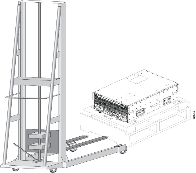
Carefully move the pallet containing the chassis to the staging area where you plan on unpacking it.

Figure 1. Unpacking the 8501 Chassis

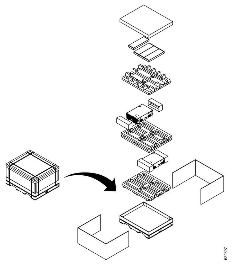
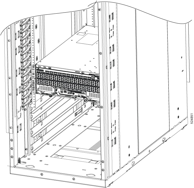
Leave the chassis on the pallet until you are ready to install the chassis in a rack.

Install Bottom-Support Rails

The bottom-support rails support the weight of the switch chassis in the rack. To maximize the stability of the rack, start attaching rails at lowest possible rack unit.

Procedure


Step 1

Position the vertical rack rails at 32" depth to match with the length of the bottom-support rails. Check spacing considerations.

Step 2

Attach the bottom-support rail to the rack using a Phillips torque screwdriver on M6 x 19 mm or 12–24 x 3/4 inch screws for each end of the rail (as shown in the following figure) and tighten each screw to 40 in-lbs (4.5 N-m) of torque.

Figure 2. Attach Bottom-Support Minipack2 Rails to a 19inch 4 Post Rack
Figure 3. Attach Bottom-Support Minipack3 Rails to a ORv3N Rack

Note

 
Use at least two screws on each end of each bottom-support rail.

Step 3

Repeat Steps 1 and 2 to attach the other bottom-support rail to the rack.

Note

 
Make sure that the two bottom-support rails are level with one another using a measuring tape. If they are not level, adjust the higher rail down to the level of the lower rail.

What to do next

Mount the chassis into the rack.

Transfer Chassis to a Mechanical Lifting Device

Procedure


Step 1

Place the mechanical lifting device in front of the chassis on the pallet as shown.

Figure 4. Align the Lifting Device in Front of the Chassis on the Pallet

Step 2

Prepare to use the mechanical lifting device by placing a piece of cardboard on the surface of the lift (to prevent scratching).

Step 3

With at least two or three people move the chassis carefully with the pallet onto the lifting device as shown.

Figure 5. Move the Chassis on to the Lifting Device

What to do next

After moving the chassis to the room or area where you will install it, begin the procedure to mount the chassis into the rack.

Mount Chassis Into the Rack

This section describes how to install the switch in a 19 inch 4-post or ORv3N rack.


Warning


Statement 1032—Lifting the Chassis

To prevent personal injury or damage to the chassis, never attempt to lift or tilt the chassis using the handles on modules, such as power supplies, fans, or cards. These types of handles are not designed to support the weight of the unit.


Warning


Statement 164—Lifting the Chassis

2 people are required to lift the heavy parts of the product. To prevent injury, keep your back straight and lift with your legs, not your back.


Warning


Statement 1006—Chassis Warning for Rack-Mounting and Servicing

To prevent bodily injury when mounting or servicing this unit in a rack, you must take special precautions to ensure that the system remains stable. The following guidelines are provided to ensure your safety:

  • This unit should be mounted at the bottom of the rack if it is the only unit in the rack.

  • When mounting this unit in a partially filled rack, load the rack from the bottom to the top with the heaviest component at the bottom of the rack.

  • If the rack is provided with stabilizing devices, install the stabilizers before mounting or servicing the unit in the rack.


Warning


Statement 1047—Overheating Prevention

To reduce the risk of fire or bodily injury, do not operate the unit in an area that exceeds the maximum recommended ambient temperature of: 104°F (40°C)


Procedure


Step 1

Remove the 16 screws, 4 screws in each corners and and lossen the 8 bolts, 2 bolts in each corner attaching the chassis to the pallet.

Step 2

Holding the switch with both hands using the handles, position the back of the switch between the front posts of the rack.

Figure 6. Inserting Chassis to the 19 inch 4 Post Rack
Figure 7. Inserting Chassis to the ORv3N Rack

Step 3

Align the two rack-mount guides on either side of the switch with the guide rails installed in the rack. Slide the rack-mount guides onto the guide rails, and then gently slide the switch all the way into the rack.

Figure 8. Aligning the Chassis in the 19 inch 4 Post Rack
Figure 9. Aligning the Chassis in the ORv3N Rack

Step 4

Tighten the 10-32 screws to 20 in-lb (2.26 N.m) or tighten the 12-24 screws to 30 in-lb (3.39 N.m).

Figure 10. Chassis installed in the 19 inch 4 Post Rack
Figure 11. Chassis installed in the ORv3N Rack

What to do next

Connect the chassis to the ground at your facility.

Locate and Ground the Chassis

This task details the procedure to ground the Cisco 8501 Switch installed in a 19 inch 4 post rack.

Note


The Cisco 8501 does not rely on chassis ground for safety. The Cisco 8501 switch installed in the ORv3N rack with the provided rack mount kit does not require direct chassis grounding via the chassis ground lug. Instead, the ORv3N rack can be properly grounded, which will adequately ground the switch as well.


Warning


Statement 1024—Ground Conductor

This equipment must be grounded. To reduce the risk of electric shock, never defeat the ground conductor or operate the equipment in the absence of a suitably installed ground conductor. Contact the appropriate electrical inspection authority or an electrician if you are uncertain that suitable grounding is available.


Warning


Statement 1101—Connected To Grounded Outlet

In the Scandinavian countries (Denmark, Finland, Iceland, Norway, and Sweden) the appliance must be connected to a grounded outlet.


Procedure


Step 1

Locate the chassis grounding receptacle on the front or rear of the chassis, in rear end upper-right corner adjacent to PSU 1 and in front upper-left corner.

Figure 12. Grounding Receptacle on the front of the Chassis
Figure 13. Grounding Receptacle on the rear of the Chassis

Step 2

Plug the one end of the grounding wire to the grounding receptacle on the switch.

Note


You can ground the switch either on the front or rear end of the chassis.

Figure 14. Ground the Chassis using Grounding Receptacle on the front of the Chassis
Figure 15. Ground the Chassis using Grounding Receptacle on the rear of the Chassis

Step 3

Connect the opposite end of the grounding wire to the appropriate grounding point at your site to ensure an adequate chassis ground.