Cisco 8101-32FH-O-C01 Switch
The Cisco 8101-32FH-O-C01 switch is a Q200L silicon chip-based switch that provides 12.8 Tbps of routing capacity. The 8101-32FH-O-C01 is a fixed-port, high density, one rack-unit form factor switch designed for data centers applications. Supported ports include 32 x 400G QSFP-DD400 GbE ports.
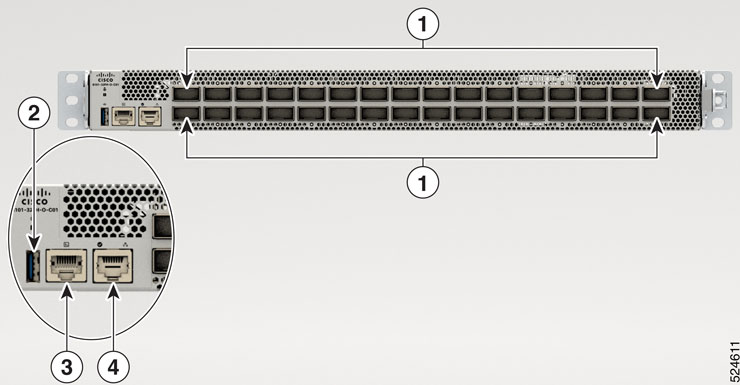
Cisco 8101-32FH-O-C01 switch front view
The front view of the switch has 32 x 400G QSFP-DD400 ports.
 Note |
The switch does not come preloaded with fans and power supply units. |
|
1 |
32 x 400G QSFP-DD400 ports |
3 |
Console |
|
2 |
USB |
4 |
Management Ethernet Port |
Cisco 8101-32FH-O-C01 switch rear view
The rear of the switch has two PSUs and six fans.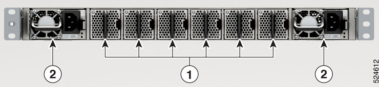
|
1 |
Fans |
|
2 |
Power supply units |
|
Module Type |
Description |
Supported Configuration |
|---|---|---|
|
Power Supply Modules |
1400W AC power module operates at 90V - 264V |
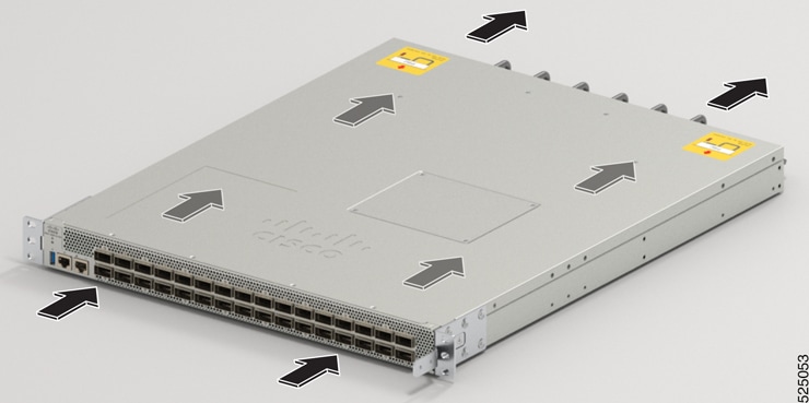
Port-Side-Intake (PSI) airflow direction. |
|
Fan Modules |
The fan modules can be removed individually. |
Port-Side-Intake (PSI) airflow direction. |
Note |
The fans and power modules have a Port-Side-Intake (PSI) configuration. |
 Feedback