Powering on the Switch

This chapter describes how to connect the power modules in the chassis and to power on the switch.

Power Supply Overview

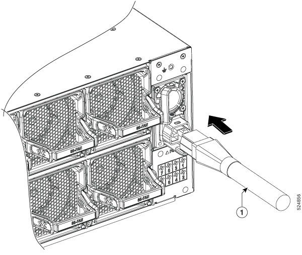
You can install up to four 3KW AC power supplies in the chassis. Ensure all power connection wiring conforms to the rules and regulations in the National Electrical Code (NEC) as well as local codes.

This table summarizes the list of power supplies' input and output power ranges for different input applications:

Power Supply Unit PIDs

Input Voltage

Input Current (Max)

Output Power

85-3KW-HVPI

180 – 305VAC

16.5A @ 200VAC

3000W

192 – 400VDC

17A DC @ 192VDC

85-3KW-DCPI

41 – 69VDC

80A @ 41VDC

3000W

Power Connection Guidelines for AC-Powered Systems

When connecting AC-input Power Supply Units (PSUs) to the site power source, observe the guidelines described here.


Warning


Statement 1028—More Than One Power Supply

This unit might have more than one power supply connection. To reduce risk of electric shock, remove all connections to de-energize the unit.


  • Ensure that the AC-input power supply module has a detachable power cord.

  • Each chassis power supply should have a separate, dedicated branch circuit.

    • North America

      • 85-3KW-HVPI —Power supply modules require a 20 A circuit.

    • International—Circuits should be sized according to local and national codes.

  • If you are using a 208 or 240 VAC power source in North America, note that such lines are considered hot and the circuit must be protected by a two-pole circuit breaker.


    Warning


    Statement 1005—Circuit Breaker

    This product relies on the building’s installation for short-circuit (overcurrent) protection. To reduce risk of electric shock or fire, ensure that the protective device is rated not greater than: 20A.


    • 20 A (North America) and 16 A (Europe) circuit breaker for an AC-input power supply module.

    • 80 A DC-rated circuit breaker for each input of a DC-input power supply module, for safety purposes - irrespective of whether the inputs are power from a single or separate DC sources.


    Warning


    Statement 1022—Disconnect Device

    To reduce the risk of electric shock and fire, a readily accessible disconnect device must be incorporated in the fixed wiring.


  • The source AC outlet must be within 9.84 to 14 feet (3.0 to 4.293 meters) of the system - depending on the length of the power cord, and should be easily accessible.

  • The AC power receptacles used to plug in the chassis must be the grounding type. The grounding conductors that connect to the receptacles should connect to protective earth ground at the service equipment level.

Power Connection Guidelines for DC-Powered Systems

When connecting DC-input Power Supply Units (PSUs) to the site power source, observe the guidelines described here.


Warning


Statement 1003—DC Power Disconnection

To reduce risk of electric shock or personal injury, disconnect DC power before removing or replacing components or performing upgrades.


Warning


Statement 1046—Installing or Replacing the Unit

To reduce risk of electric shock, when installing or replacing the unit, the ground connection must always be made first and disconnected last.

If your unit has modules, secure them with the provided screws.


Warning


Statement 1022—Disconnect Device

To reduce the risk of electric shock and fire, a readily accessible disconnect device must be incorporated in the fixed wiring.


Warning


Statement 1024—Ground Conductor

This equipment must be grounded. To reduce the risk of electric shock, never defeat the ground conductor or operate the equipment in the absence of a suitably installed ground conductor. Contact the appropriate electrical inspection authority or an electrician if you are uncertain that suitable grounding is available.


Warning


Statement 1033—Safety Extra-Low Voltage (SELV)—IEC 60950/ES1–IEC 62368 DC Power Supply

To reduce the risk of electric shock, connect the unit only to a DC power source that complies with the SELV requirements in the IEC 60950-based safety standards or the ES1 requirements in the IEC 62368-based safety standards.


  • All power connection wiring should conform to the rules and regulations prescribed by the National Electrical Code (NEC), as well as local codes, if any.

  • The DC return must remain isolated from the system frame and the chassis (DC-I).

    The color coding of the source DC power cable leads depends on the color coding of the site DC power source. Typically, green or green and yellow stripes indicate that the cable is a ground cable. Since there is no color code standard for source DC wiring, you must ensure that the power cables are connected to the DC-input power supply terminal block in the proper + and - polarity.

    In some cases, the source DC cable leads might have a positive (+) or a negative (–) label. This label is a relatively safe indication of polarity, but you must verify the polarity by measuring the voltage between the DC cable leads. When measuring, ensure that the positive lead and the negative lead always match the "+" and "-" labels on the DC-input power supply terminal block, respectively.

  • DC power cables use the M-CRPS connector at the power supply end.

  • The circuit must be protected by a dedicated two-pole DC-rated circuit breaker.

    The circuit breaker is considered to be the disconnect device and must be easily accessible. For DC-input power supply units with multiple inputs, each DC input must be protected by a dedicated DC-rated circuit breaker or a fuse.

    The circuit breaker or fuse should be sized according to the power supply input rating and local or national code requirements.

  • If the DC inputs are powered from separate sources, the cables must be wired straight across to their respective sources and terminals.

    Crossed cables in a setup where the DC source has floating outputs means that no damage will occur, but the LEDs will not light up, and the module will not operate.

    Crossed cables in a setup with a positive ground or a negative ground power system constitute a severe safety hazard that includes causing electric shock and generating excessive EMI and RFI.


    Note


    In the illustration, the red and black cables do not interconnect. The two black cables are connected to the same negative output of the DC source; the two red cables are connected to the same positive output of the DC source.


Connect AC Power to the Chassis


Warning


Statement 1017—Restricted Area

This unit is intended for installation in restricted access areas. Only skilled, instructed, or qualified personnel can access a restricted access area.


Warning


Statement 1005—Circuit Breaker

This product relies on the building’s installation for short-circuit (overcurrent) protection. To reduce risk of electric shock or fire, ensure that the protective device is rated not greater than:

AC: 20A, DC: 40A


Warning


Statement 1028—More Than One Power Supply

This unit might have more than one power supply connection. To reduce risk of electric shock, remove all connections to de-energize the unit.


Warning


Statement 1003—DC Power Disconnection

To reduce risk of electric shock or personal injury, disconnect DC power before removing or replacing components or performing upgrades.


Warning


Statement 1046—Installing or Replacing the Unit

To reduce risk of electric shock, when installing or replacing the unit, the ground connection must always be made first and disconnected last.

If your unit has modules, secure them with the provided screws.


Warning


Statement 1022—Disconnect Device

To reduce the risk of electric shock and fire, a readily accessible disconnect device must be incorporated in the fixed wiring.


Warning


Statement 1029—Blank Faceplates and Cover Panels

Blank faceplates and cover panels serve three important functions: they reduce the risk of electric shock and fire, they contain electromagnetic interference (EMI) that might disrupt other equipment, and they direct the flow of cooling air through the chassis. Do not operate the system unless all cards, faceplates, front covers, and rear covers are in place.


Caution


The chassis relies on the protective devices in the building installation to protect against short circuit, overcurrent, and ground faults. Ensure that the protective devices comply with local and national electrical codes.

Note


We recommend that you occupy all power supply slots of the switch with power supplies. In case a power module fails, it is recommended to retain the failed power module in its slot until it is replaced with a new power module. This recommendation ensures that the system airflow is not impacted adversely, which may then result in the overheating of the switch and its components.

Note


A dual pole breaker is needed for installation. For determining the recommended breaker size, please adhere to local and national rules and regulations. The breaker size is based on the specifications of the product for the current drawn and the specified voltage level.

Procedure


Step 1

Verify that the AC cable is installed in the correct AC source and outlet type.

Step 2

Attach the AC power cable to the cable connector in the AC power module.

Figure 1. Connecting AC Power

1

AC power cable

Note

 
These switches are designed to boot up in less than 30 minutes, provided the neighboring devices are in full operational state.

Connect DC Power to the Chassis


Caution


The chassis relies on the protective devices in the building installation to protect against short circuit, overcurrent, and ground faults. Ensure that the protective devices comply with local and national electrical codes.


Note


We recommend that you occupy only the left slot of the rear power supply slots of the fixed port switches with power supply. In the right slot you must install the blank power supply. This recommendation ensures that the system airflow is not impacted adversely, which may then result in the overheating of the switch and its components.

Procedure


Step 1

Verify that the correct fuse panel is installed in the top mounting space.

Step 2

Ensure that the DC circuit is powered down (either breaker turned off or fuse pulled) and proper lockout tag out procedures are followed. Use the cable supplied with the power supply. You can purchase power supply cord separately from Cisco.

Step 3

Dress the power according to local practice.

Step 4

Connect the office battery and return cables according to the fuse panel engineering specifications.

Step 5

Insert the DC connector into the DC receptacle on the power supply.

Figure 2. Connecting DC Power

1

DC power cable

Figure 3. DC Power Cable

Step 6

Ensure that the locking mechanism has engaged to secure the cable.

Note


When removing the DC cable from the power supply unit (PSU), gently engage the tab to unlock the cable from the PSU. Do not use the pull tab to extract the entire PSU, as this may lead to tab breakage.

Step 7

Turn on the circuit breaker at the power source.


Power Supply Power Cord Specifications


Note


Always use the Saf-D-Grid connector toward the switch.
Table 1. Standard AC and HVDC Power Cords

Locale

Part Number

Cisco Part Number (CPN)

Power Cord Set Rating

Connector Part Number

Power Cord Illustration

IEC/EU, US, CANADA, MEXICO, BRAZIL, NETHERLANDS, IRELAND, FRANCE, UK, GERMANY, SWITZERLAND, NORWAY, SPAIN, ITALY, SINGAPORE, CHINA, SOUTH AFRICA

CAB-AC-25A-NA

37-101481-01

25A, 250VAC

Saf-D-Grid 3-5958P2 to IEC 60320 C20

Refer the figure in

Power Cord Illustrations

IEC/EU, US, CANADA, MEXICO, BRAZIL, NETHERLANDS, IRELAND, FRANCE, UK, GERMANY, SWITZERLAND, NORWAY, SPAIN, ITALY, SINGAPORE, CHINA, SOUTH AFRICA

PWR-3KW-DC-CBL

37-101461-01

Refer the figure in

Power Cord Illustrations

Power Cord Illustrations

Figure 4. CAB-AC-25A-NA Power Cord and Plugs for Standard AC Power Supply
Figure 5. PWR-3KW-DC-CBL Power Cord and Plugs for Standard DC Power