Cisco 8101-32FH-O-C01 Switch

Introduction

The Cisco 8101-32FH-O-C01 switch is a Q200L silicon chip-based switch that provides 12.8 Tbps of routing capacity. The 8101-32FH-O-C01 is a fixed-port, high density, one rack-unit form factor switch designed for data centers applications. Supported ports include 32 x 400G QSFP-DD400 GbE ports.

Cisco 8101-32FH-O-C01 switch front view

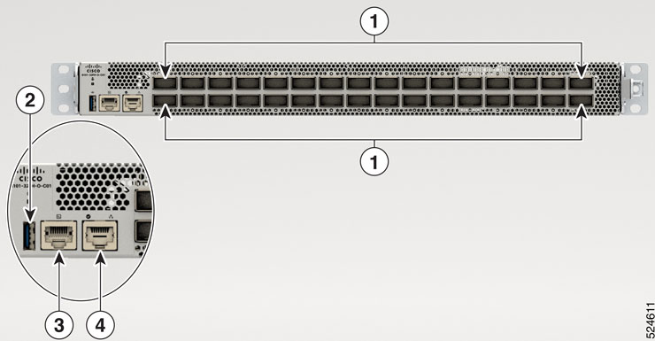
The front view of the switch has 32 x 400G QSFP-DD400 ports.


Note


The switch does not come preloaded with fans and power supply units.


Figure 1. Cisco 8101-32FH-O-C01 - front view

1

32 x 400G QSFP-DD400 ports

3

Console

2

USB

4

Management Ethernet Port

Cisco 8101-32FH-O-C01 switch rear view

The rear of the switch has two PSUs and six fans.
Figure 2. 8101-32FH-O-C01 - rear view

1

Fans

2

Power supply units

Table 1. Cisco 8101-32FH-O-C01 switch rear view description

Module Type

Description

Supported Configuration

Power Supply Modules

1400W AC power module operates at 90V - 264V

Port-Side-Intake (PSI) airflow direction.

Fan Modules

The fan modules can be removed individually.

Port-Side-Intake (PSI) airflow direction.


Note


The fans and power modules have a Port-Side-Intake (PSI) configuration.


Temperature and physical specifications

For temperature and physical specifications, refer to the Physical characteristics table in the Cisco 8100 Series Switches Data Sheet.

Weight and power consumption

For weight and power consumption, refer to the Physical characteristics table in the Cisco 8100 Series Switches Data Sheet.

Airflow directions

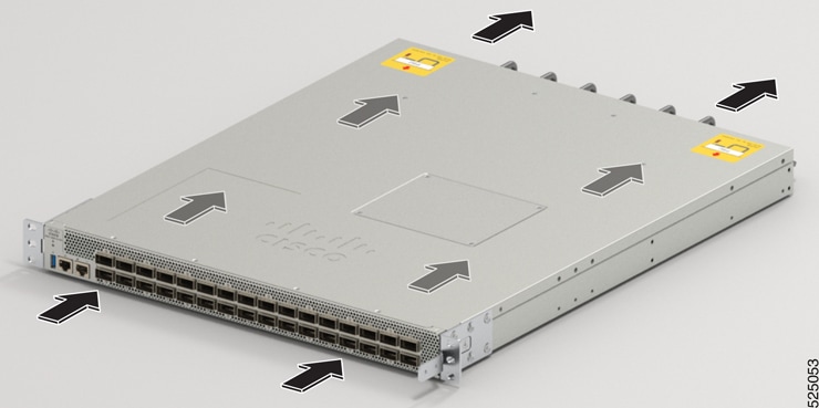
The Cisco 8101-32FH-O-C01 switch supports the Post-Side Intake (PSI) version-2 configuration. In the PSI configuration, the airflow through both the fan trays and power supplies is from the front-side to the rear-side.

Figure 3. Airflow direction for Cisco 8101-32FH-O-C01 switch

To ensure proper airflow for the switch in your facility, position the switch with its air intake on a cold aisle and the air exhaust on a hot aisle.


Note


The airflow direction must be the same for all power supply and fan modules in the switch.


Maximum power available to switch

The maximum power available to the switch depends on these factors:

  • the input power from your power source

  • the number of Power Supply Units (PSUs)

  • the output capabilities of the PSUs

  • the power redundancy mode that you use

The following table lists the amount of power available for Cisco 8100 series switchs from all available power trays.

Table 2. Maximum power available

Number of PSUs

Combined Mode in Watts (No redundancy)

1+1 Redundancy Mode in Watts (with Single Supply Loss)

1

1400

Yes


Note


When the AC power supply unit operates at the line voltage range of 90VAC to 140VAC, the switch does not support 1+1 redundancy mode.