Install the switch


Note


The images in this chapter are only for representation purposes, unless specified otherwise. The switch' actual appearance and size may vary.

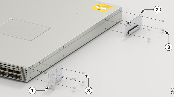
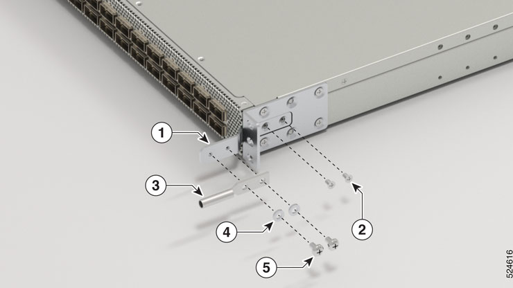
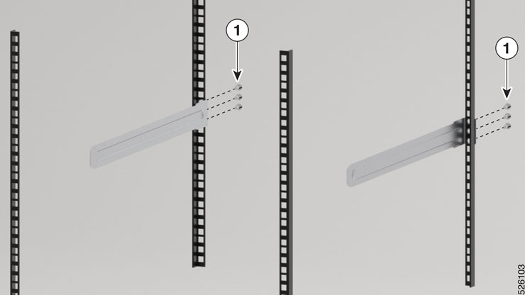
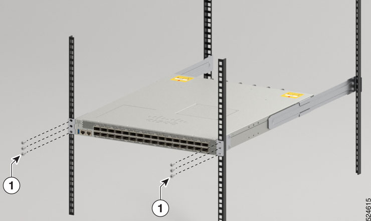
Rack mount the chassis

The switch can be mounted on a 4-post rack.


Warning


Statement 1006—Chassis Warning for Rack-Mounting and Servicing

To prevent bodily injury when mounting or servicing this unit in a rack, you must take special precautions to ensure that the system remains stable. The following guidelines are provided to ensure your safety:

  • This unit should be mounted at the bottom of the rack if it is the only unit in the rack.

  • When mounting this unit in a partially filled rack, load the rack from the bottom to the top with the heaviest component at the bottom of the rack.

  • If the rack is provided with stabilizing devices, install the stabilizers before mounting or servicing the unit in the rack.


Warning


Statement 1032—Lifting the Chassis

To prevent personal injury or damage to the chassis, never attempt to lift or tilt the chassis using the handles on modules, such as power supplies, fans, or cards. These types of handles are not designed to support the weight of the unit.


Warning


Statement 1098—Lifting Requirement

people are required to lift the heavy parts of the product. To prevent injury, keep your back straight and lift with your legs, not your back.


Note


Statement 4023—Product Usage Restrictions

This product is designed for indoor usage only. Outdoor usage is not permitted.


Mount Cisco 8101-32FH-O-C01 switch in a 4-post rack

This section describes how to use the rack-mount kit provided with the Cisco 8101-32FH-O-C01 switch, to install the switch into a cabinet or a 4-post 19-inch rack.


Caution


If the rack is on wheels, ensure that the brakes are engaged or that the rack is otherwise stabilized.

For a complete list of items contained in the 4-post rack-mount kit (8101-INSTKIT-C01) provided with the switch, see Accessory Kit.


Note


The fan and power modules use the port side intake (PSI) configuration.


Procedure


Step 1

Install the rack-mount brackets on the switch (Refer to item 1 in Figure 7). Ensure that you position the fan modules and power modules on the switch such that the ports are in the cold aisle.

  1. Position a rack-mount bracket on the side of the switch with its six holes that are aligned to six of the screw holes on the side of the switch, and then use six M4 flat-head screws with 13.25 in-lbs (1.5 N-m) torque value to attach the bracket to the switch.

    Note


    You can align six holes in the rack-mount bracket to six screw holes on the front side of switch or four screw holes on the rear side of the switch. The holes that you use depend on which end of your switch is located in the cold aisle.

  2. Repeat step 1b with the other rack-mount bracket on the other side of the switch.

Step 2

Install the rack-mount guide on the switch. (Refer to item 2 in Figure 7)

  1. Position a rack-mount guides on the side of the switch with its six holes aligned to the six screw holes on the side of the switch, and use two M4 flat-head screws to attach the guides to the switch. Tighten the screws to a torque of 13.25 in-lb (1.5 N-m).

  2. Repeat Step 2a with the other rack-mount bracket on the other side of the switch.

Figure 1. Attach rack-mount bracket on the front side and attach rack-mount guide on rear side

1

Rack mount bracket

2

Rack mount guide

3

2x M4 x 6mm flat-head screws

Step 3

Attach the ground lug bracket to the switch (refer to item 1 in Figure 8).

  1. Position the ground lug extension bracket on the switch.

  2. Use two M4 x 7mm Phillips flat-head screws with 13.25 in-lbs (1.5 N-m) torque value to attach the ground lug extension bracket to the switch.

Note


The ground lug bracket installation must be done before the switch is installed onto the rack. The grounding lug itself can be installed after the switch is mounted in the rack.

Step 4

Install the rack-mount guide rails to the rack.

  1. Position the rack-mount guide rails at the desired levels on the back side of the rack and use four 12-24 screws or four 10-32 screws, depending on the rack thread type, to attach the rails to the rack.

  2. Repeat with the other rack-mount guide rail on the other side of the switch.

  3. Use a tape measure and level to verify that the rails are at the same height and horizontal.

Figure 2. Attach ground lug bracket and ground lug

1

Ground lug bracket

2

2x M4 x 7mm Phillips flat-head screws on each side

3

Ground lug

4, 5

2x M4 x 6mm pan-head screws

Step 5

Insert the switch into the rack and attach:

  1. Holding the switch with both the hands, position the back of the switch between the front posts of the rack.

  2. Align the two rack-mount guides on either side of the switch with the guide rails installed in the rack. Slide the rack-mount guides onto the guide rails, and then gently slide the switch all the way into the rack.

    Note


    If the switch does not slide easily, try realigning the rack-mount guides on the guide rails.

    Figure 3. Insert switch into the rack

    1

    Insert the screws to attach the switch to the rack.

Step 6

Holding the switch level, insert four screws (12-24 or 10-32, depending on the rack type) through the holes in each of the rack-mount brackets and into the cage nuts or threaded holes in the rack-mounting rail.

Figure 4. Attach switch to the rack

1

Insert the screws to attach the switch to the rack.

Step 7

Attach the ground lug to the ground lug bracket (refer to item 3 in Figure 8).

  1. Position the ground lug onto the previously installed ground lug bracket.

  2. Use two M4 x 6mm pan-head screws to attach the ground lug to the bracket.

Step 8

Tighten the 10-32 screws to 20 in-lb (2.26 N.m) or tighten the 12-24 screws to 30 in-lb (3.39 N.m).


Ground the switch


Warning


Statement 1024—Ground Conductor

This equipment must be grounded. To reduce the risk of electric shock, never defeat the ground conductor or operate the equipment in the absence of a suitably installed ground conductor. Contact the appropriate electrical inspection authority or an electrician if you are uncertain that suitable grounding is available.


Warning


Statement 1046—Installing or Replacing the Unit

To reduce risk of electric shock, when installing or replacing the unit, the ground connection must always be made first and disconnected last.

If your unit has modules, secure them with the provided screws.


Warning


Statement 1101—Connected To Grounded Outlet

In the Scandinavian countries (Denmark, Finland, Iceland, Norway, and Sweden) the appliance must be connected to a grounded outlet.


Warning


Statement 2004—Grounded Equipment

This equipment is intended to be grounded to comply with emission and immunity requirements. Ensure that the switch functional ground lug is connected to earth ground during normal use.


Note


Statement 7015—Equipment Bonding and Grounding

When you use thread-forming screws to bond equipment to its mounting metalwork, remove any paint and nonconductive coatings and clean the joining surfaces. Apply an antioxidant compound before joining the surfaces between the equipment and mounting metalwork.


Caution


Grounding the switch is required, even if the rack is already grounded. A grounding pad with two threaded holes is provided on the switch for attaching either a grounding lug or grounding plate. The ground lug must be NRTL-listed. In addition, a copper conductor (wires) must be used and the copper conductor must comply with NEC code for ampacity.

Caution


When terminating the frame ground, do not use soldering lug connectors, screwless (push-in) connectors, quick connect connectors, or other friction-fit connectors.

Procedure


Step 1

Use a wire-stripping tool to remove approximately 0.75 inches (19 mm) of the covering from the end of the #6 AWG grounding cable.

Step 2

Insert the stripped end of the grounding cable into the open end of the grounding lug.

Step 3

Use the crimping tool to secure the grounding cable in the grounding lug.