
Replace fan modules
 Note |
The airflow direction must be the same for all power supply and fan modules in the switch. |
|
Fan Module |
PID |
|---|---|
|
Port-side intake airflow |
FAN-1RU-PI-C01 |
Procedure
|
Step 1 |
Press the latch on the fan module and grasp the handle of fan module. 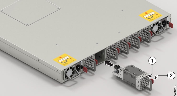
|
||||
|
Step 2 |
Pull the handle to remove the fan to be replaced. |
||||
|
Step 3 |
Hold the fan module with the LED and PID label at the top. |
||||
|
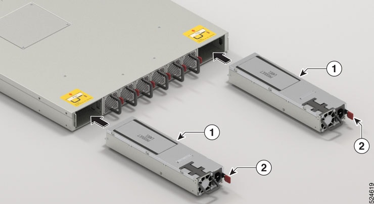
Step 4 |
Align the fan module to the open fan tray slot in the switch, and press the module all the way into the slot until the latch clicks and is locked on the switch. If the fan module does not go all the way into the slot, do not force it. Remove the fan module and verify that it is the correct type for your switch and in the correct orientation. To verify the status of fans and the speed, use the show environment fan command. |
||||
|
Step 5 |
If the switch is powered on, listen for the fans. You should immediately hear them operating. If you do not hear them, ensure that the fan module is inserted completely in the switch. |
||||
|
Step 6 |
Verify that the fan module LED is green. If the LED is not green, one or more fans are faulty. If this situation occurs, contact your customer service representative for replacement parts. |
 Feedback