Power on the switch

This chapter explains how to connect the switch's power modules and power it on.

Power supply

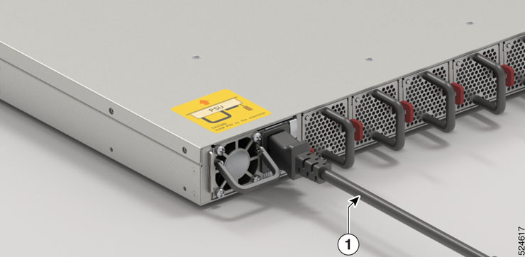
You can install one 1400 watt AC power supply in the switch. Ensure that all power connection wiring conforms to the rules and regulations in the National Electrical Code (NEC) and in local codes.

Module Type

Description

Nominal Range

AC Power

single feed with 1400 W capacity at 90-264 V

Inpit Voltage

Output Power Main Output Standby Output

90V—140V

180V—264V

1000W/36W

1450W/36W

12V/84A

12V/121A

12V/3A

Power supply unit input and output ranges

Power supply restrictions and considerations


Warning


Statement 1028—More Than One Power Supply

This unit might have more than one power supply connection. To reduce risk of electric shock, remove all connections to de-energize the unit.


Warning


Statement 1005—Circuit Breaker

This product relies on the building’s installation for short-circuit (overcurrent) protection. To reduce risk of electric shock or fire, ensure that the protective device is rated not greater than:


  • 20 A (North America) and 16 A (Europe) circuit breaker for an AC-input power supply module.


Warning


Statement 1022—Disconnect Device

To reduce the risk of electric shock and fire, a readily accessible disconnect device must be incorporated in the fixed wiring.


Warning


Statement 1090—Installation by Skilled Person

Only a skilled person should be allowed to install, replace, or service this equipment. See statement 1089 for the definition of a skilled person.


Warning


Statement 1091—Installation by an Instructed Person

Only an instructed person or skilled person should be allowed to install, replace, or service this equipment. See statement 1089 for the definition of an instructed or skilled person.


Warning


Statement 1073—No User-Serviceable Parts

There are no serviceable parts inside. To avoid risk of electric shock, do not open.


Warning


Statement 1099—Before Connecting to System Power Supply

High touch/leakage current—Permanently connected protective earth ground is essential before connecting to the system power supply.


Warning


Statement 1100—Before Making Telecommunication Network Connection

High touch/leakage current—Permanently connected protective earth ground is essential before connecting to the telecommunication network.


Limitations and guidelines

  • Use one type of power supply in a switch.

  • The power supply type that is used in the switch depends on the type and configuration of the transceivers installed in it.

  • The airflow direction must be the same for all power supply and fan modules in the switch.

  • The AC-input power supplies support low-line voltage of 120V (Nominal) and high-line voltage of 220V (Nominal). If you need to change voltage type after installation, disconnect the feed from the power supply before switching the input voltage level.

Connect AC power to the switch


Caution


The switch relies on the protective devices in the building installation to protect against short circuit, overcurrent, and ground faults. Ensure that the protective devices comply with local and national electrical codes.

Note


We recommend that you occupy both the power supply slots of the fixed port switch with power supplies. In case a power module fails, it is recommended to retain the failed power module in its slot until it is replaced with a new power module. This recommendation ensures that the system airflow is not impacted adversely, which may then result in the overheating of the switch and its components.

Warning


Statement 1017—Restricted Area

This unit is intended for installation in restricted access areas. Only skilled, instructed, or qualified personnel can access a restricted access area.


Warning


Statement 1003—DC Power Disconnection

To reduce risk of electric shock or personal injury, disconnect DC power before removing or replacing components or performing upgrades.


Warning


Statement 1046—Installing or Replacing the Unit

To reduce risk of electric shock, when installing or replacing the unit, the ground connection must always be made first and disconnected last.

If your unit has modules, secure them with the provided screws.


Warning


Statement 1022—Disconnect Device

To reduce the risk of electric shock and fire, a readily accessible disconnect device must be incorporated in the fixed wiring.


For Cisco 8101-32FH-O-C01 switch, these power supplies are supported:

  • PSU PID: PSU1.4KW-ACPI – 1400W AC, port-side intake airflow.


Important


  • System shall not operate at input voltage: 100-127VAC, 50/60Hz with a single AC power supply condition.

  • System shall operate at input voltage: 100-127VAC, 50/60Hz with dual AC power supply condition.


Note


A dual pole breaker is needed for installation. For determining the recommended breaker size, please adhere to local and national rules and regulations. The breaker size is based on the specifications of the product for the current drawn and the specified voltage level.

Procedure


Step 1

Verify that the AC cable is installed in the correct AC source and outlet type.

Step 2

Attach the AC power cable to the cable connector in the AC power module.

Step 3

Place the cable through the opening in the cable tie.

Step 4

Slide the cable tie toward the plug.

Step 5

Close the cable tie on the shoulder of the power cable to secure the power cable.

Figure 1. Connecting AC power - Cisco 8101-32FH-O-C01

1

AC power cable


AC-Input power cord options

This table summarises the input and output power ranges for PSU high line applications:

AC-input power cord options for Cisco 8101-32FH-O-C01 switch

Table 1. AC-input power cord options for Cisco 8101-32FH-O-C0-1 switch

Locale

Part Number

Length

Power Cord Rating

Australia, New Zealand

CAB-AC-10A-ANZ

14 ft (4.26 m)

10A, 250 VAC

Brazil

CAB-AC-10A-BRZ

14 ft (4.26 m)

10A, 250 VAC

Britain

CAB-AC-10A-GBR

14 ft (4.26 m)

10A, 250 VAC

China

CAB-AC-10A-CHN

14 ft (4.26 m)

10A, 250 VAC

Denmark

CAB-AC-10A-DEN

14 ft (4.26 m)

10A, 250 VAC

Europe

CAB-AC-10A-EU

14 ft (4.26 m)

10A, 250 VAC

Italy

CAB-AC-10A-ITA

14 ft (4.26 m)

10A, 250 VAC

Japan

CAB-AC-10A-JPN1

14 ft (4.26 m)

10A, 250 VAC

Japan

CAB-AC-10A-JPN2

14 ft (4.26 m)

10A, 250 VAC

Korea

CAB-AC-10A-KOR

14 ft (4.26 m)

10A, 250 VAC

North America

CAB-AC-10A-NA

14 ft (4.26 m)

13A, 125 VAC

Switzerland

CAB-AC-10A-CHE

14 ft (4.26 m)

10A, 250 VAC

Figure 2. CAB-AC-10A-NA