Enhanced Classic LAN in Cisco Nexus Dashboard Release 4.1.1
Available Languages
Bias-Free Language
The documentation set for this product strives to use bias-free language. For the purposes of this documentation set, bias-free is defined as language that does not imply discrimination based on age, disability, gender, racial identity, ethnic identity, sexual orientation, socioeconomic status, and intersectionality. Exceptions may be present in the documentation due to language that is hardcoded in the user interfaces of the product software, language used based on RFP documentation, or language that is used by a referenced third-party product. Learn more about how Cisco is using Inclusive Language.
- US/Canada 800-553-2447
- Worldwide Support Phone Numbers
- All Tools
 Feedback
 Feedback
What is Cisco Nexus Dashboard Fabric Controller?
Use Case 1: Classic LAN Networks (Brownfield and Greenfield)
Use Case 2: Coexistence of Brownfield Classic LAN and Greenfield VXLAN
Cisco Nexus Dashboard for Classic LAN
Topologies supported for Classic LAN
Topology 1: 3 Tier Hierarchical (Access, Aggregation, Core)
Topology 2: Collapsed Core (Access, Core)
External Connectivity from Enhanced Classic LAN
Guidelines and Limitations for Enhanced Classic LAN
Hardware and Software Recommendations
For the Access and Aggregation Layers
Step 2: Discover the Switches in the Fabric
Step 3. Bootstrap (Power-on Auto-provisioning)
Step 5: Configure the vPC pairing
Step 6: Recalculate and Deploy
Step 3: Review Pending Configurations on Access and Aggregation
Step 4: Deploy the Configuration
Layer 3 Network in the Default VRF Instance
Step 2: Attach the Network and Choose the FHRP Master per Network
Step 3: Review Pending Configurations on the Access and Aggregation Layer
Step 4: Deploy the Configuration
Layer 3 Network with a Custom VRF Instance
Step 2: Create a VRF Instance to Link a Custom VRF Instance to This Layer 3 Network
VRF-Lite Extension Between the Aggregation and Core/Edge Layers
Step 3: Deploy on Aggregations
VRF-Lite extension between Collapsed Core and WAN
Integration of Classic LAN with Services
VRF-Lite Using Routed Interfaces or Port Channels
ND with Legacy Nexus Platforms
ND with Newer Cisco Nexus Platforms (Cisco Nexus 9000) Considering FEX
Layer 2/Layer 3 Demarcation at the Core Layer
Migration from Classic LAN and VXLAN Networks
Given the broad deployment of classic hierarchical networks and the CLI-driven methodology to push changes, data centers need a simplified, automated, SDN driven approach for day 0, day 1, and day 2 aspects of such Ethernet-based networks. Such networks typically consist of Access, Aggregation, and Core layers.
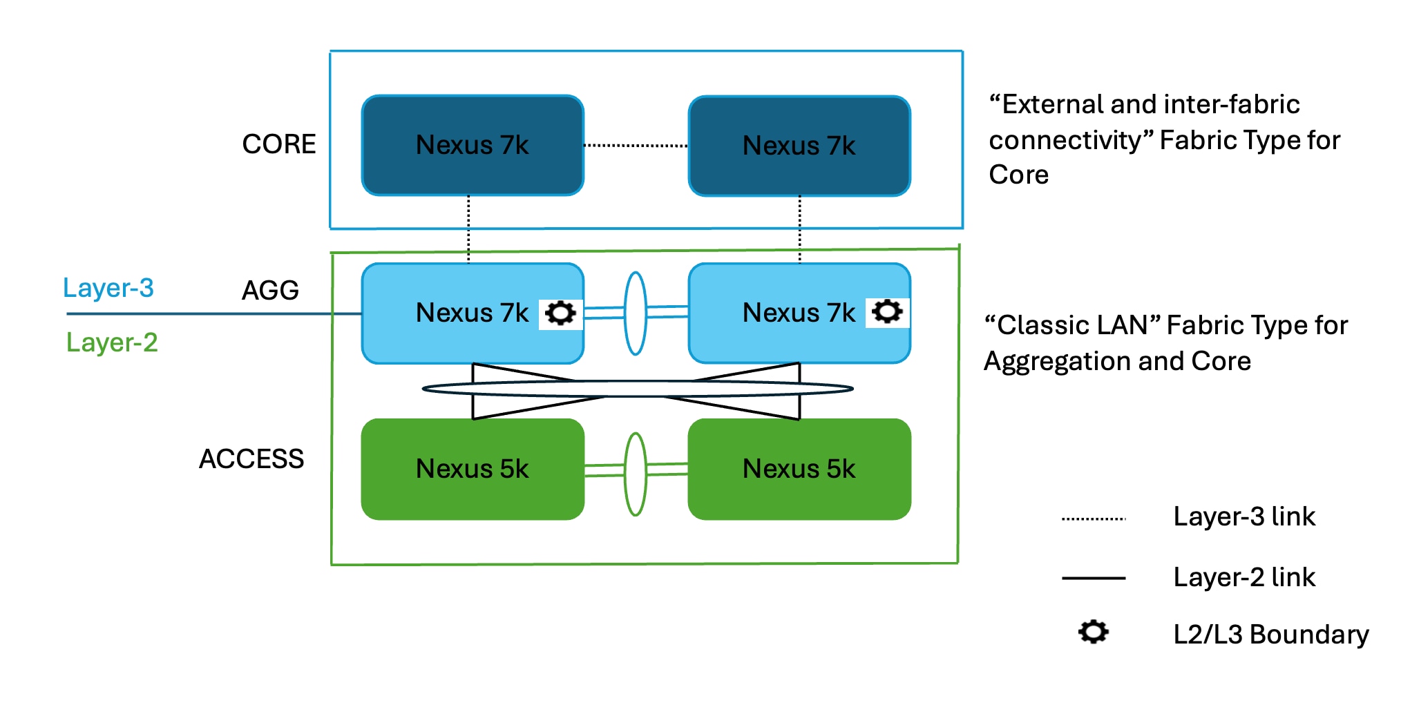
The Access layer is where the server chassis is connected. The Aggregation layer is the Layer 3 and Layer 2 boundary for the data center infrastructure. In common designs, the Aggregation layer is also the connection point for data center firewalls and other services. The Core layer provides the interconnection of multiple data center Aggregation modules. While Layer 2/Layer 3 demarcation is typically at the Aggregation layer, in some cases the demarcation can be at the Access layer (routed access networks, for example) or Core layer.
This document is a deep dive into Classic Ethernet networks and how the Enhanced Classic LAN fabric type introduced in Cisco Nexus Dashboard (ND) release 4.1.1 can manage, maintain, and monitor them. This whitepaper covers the end-to-end deployment of switches in such networks, the prerequisites to start using ND, and the Nexus hardware recommendations at each layer.
What is Cisco Nexus Dashboard?
Cisco Nexus Dashboard is a central management console for multiple data center fabrics that provides real-time analytics, visibility, assurance for network policies and operations, as well as policy orchestration for the data center fabrics, such as Cisco ACI and NX-OS.
Nexus Dashboard provides a common platform and modern technology stack, simplifying the life cycle management of different modern applications and reducing the operational overhead to run and maintain these applications. It also provides a central integration point for external 3rd party applications with the locally hosted applications.
Nexus Dashboard is the comprehensive management solution for NX-OS deployments spanning LAN fabric, SAN fabric, and IP Fabric for Media (IPFM) networks in data centers powered by Cisco. Nexus Dashboard also supports other devices, such as IOS-XE switches, IOS-XR routers, and non-Cisco devices. Being a multi-fabric controller, Nexus Dashboard manages multiple deployment models such as VXLAN EVPN, classic 3-tier, FabricPath, and routed-based fabrics for LAN while providing ready-to-use control, management, monitoring, and automation capabilities for all these environments.
In earlier releases, Nexus Dashboard shipped with only the platform software and no services included which you would then download, install, and enable separately after the initial platform deployment. Now, the platform and individual services have been unified into a single product. You no longer deploy and configure the services separately.
Nexus Dashboard is offered as a cluster of specialized Cisco UCS servers (Nexus Dashboard platform) with the software framework (Nexus Dashboard) pre-installed on it. The Cisco Nexus Dashboard software stack can be decoupled from the hardware and deployed in a number of virtual form factors. For the purposes of this document, we will use "Nexus Dashboard hardware" specifically to refer to the hardware and "Nexus Dashboard" to refer to the software stack and the GUI console.
A basic Nexus Dashboard deployment for on-Premises hosting is supported on Physical as well as Virtual Appliance.
Starting with the 4.1.1 release, we also have support for Cloud (AWS) form factor for Controller and telemetry.
Please refer Nexus Dashboard Capacity planning tool, to view the supported cluster sizes and scale.
For details on the number of secondary (worker) and standby nodes that can be added, please refer to “Scale of Primary, Secondary, and Standby Nodes” section of the document Deploying Highly Available Services with Cisco Nexus Dashboard.
The use cases fall into two main categories (keeping in mind ND acting as the controller for these use cases)
Use Case 1: Classic LAN Networks (Brownfield and Greenfield)
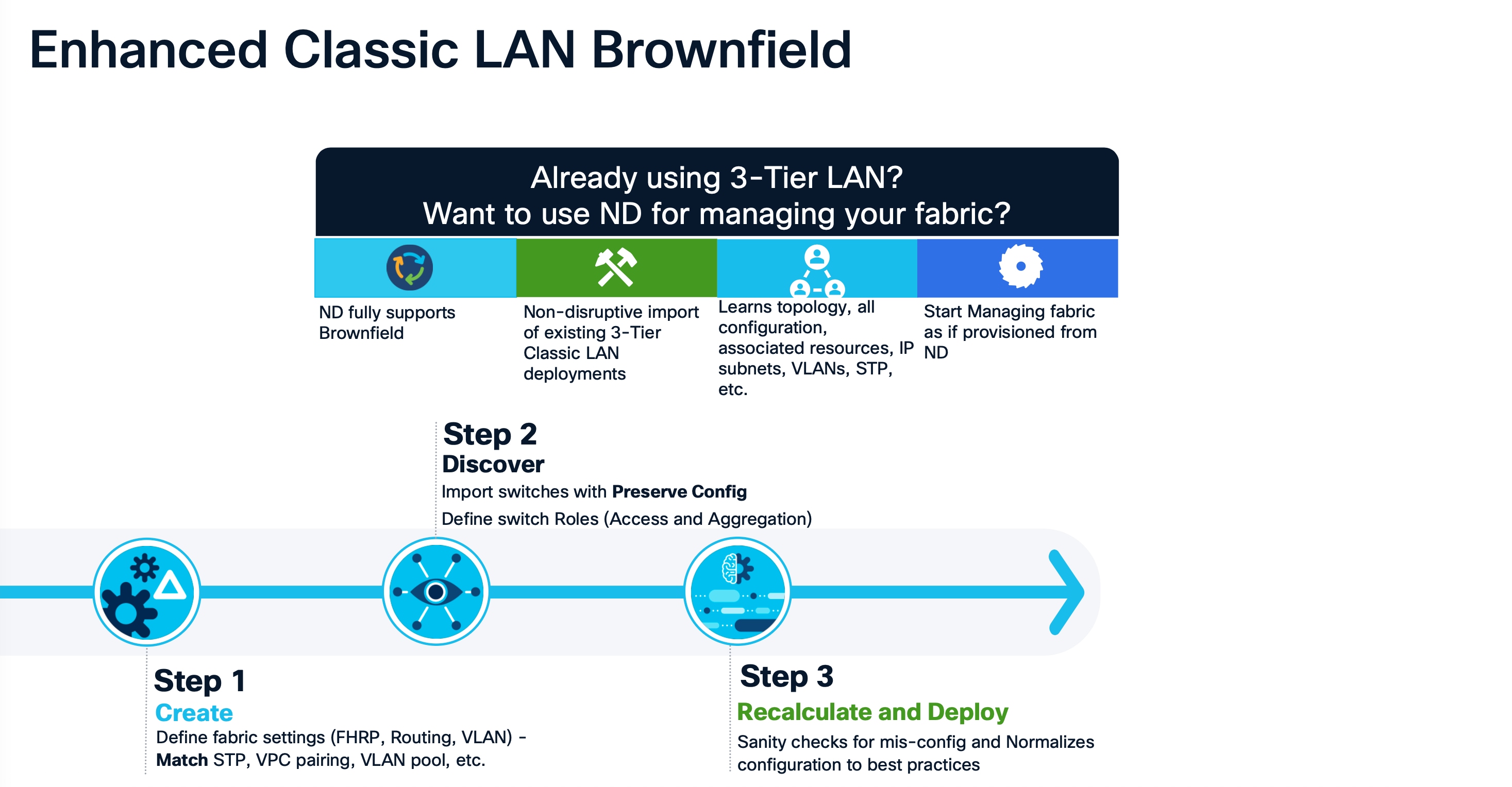
This use case entails the management of single or multiple 2 or 3 Tier Hierarchical networks comprised of Nexus platforms. Existing networks managed by CLI or other mechanisms can be imported into ND with full support for Brownfield (i.e., all intent will be learned by ND, and configurations on switches will be preserved), making this a non-disruptive operation. These networks can then be incrementally managed and maintained by ND. For any new deployments (Greenfield), Cisco best practice embedded templates in ND can be leveraged to provide end-to-end network connectivity.
Use Case 2: Coexistence of Brownfield Classic LAN and Greenfield VXLAN
This use case entails the coexistence of Classic LAN and VXLAN EVPN networks – A hybrid of vPC/Spanning Tree, 3-tier architecture, and an overlay-based Leaf-Spine VXLAN architecture, all within the same ND cluster. This option is for customers who plan to migrate workloads to an evolved VXLAN network but are currently on Classic Ethernet. ND can be leveraged for brownfield import of these existing Classic networks and manage them incrementally. ND templates can be used to build VXLAN BGP EVPN underlay and overlay from scratch (Greenfield). Once both architectures are up and running, ND can be used to migrate workloads from Classic to VXLAN networks. Classic LAN can thereafter be deprecated once all the migration is complete, and customers are comfortable with VXLAN as technology.
This white paper delves into each of the use cases.
Cisco Nexus Dashboard for Classic LAN
"Enhanced Classic LAN" was introduced as a new fabric template in ND release 12.1.3. In Cisco Nexus Dashboard Release 4.1.1 this template continues to completely automate the Layer 2 and Layer 3 aspects of Access–Aggregation-Core, as per Cisco best practices. This minimizes the learning curve and makes it easy to move to an SDN-driven approach, all while preparing for the future by improving scalability, creating the opportunity to build overlays with VXLAN, and offering a wide variety of maintenance and operational features.
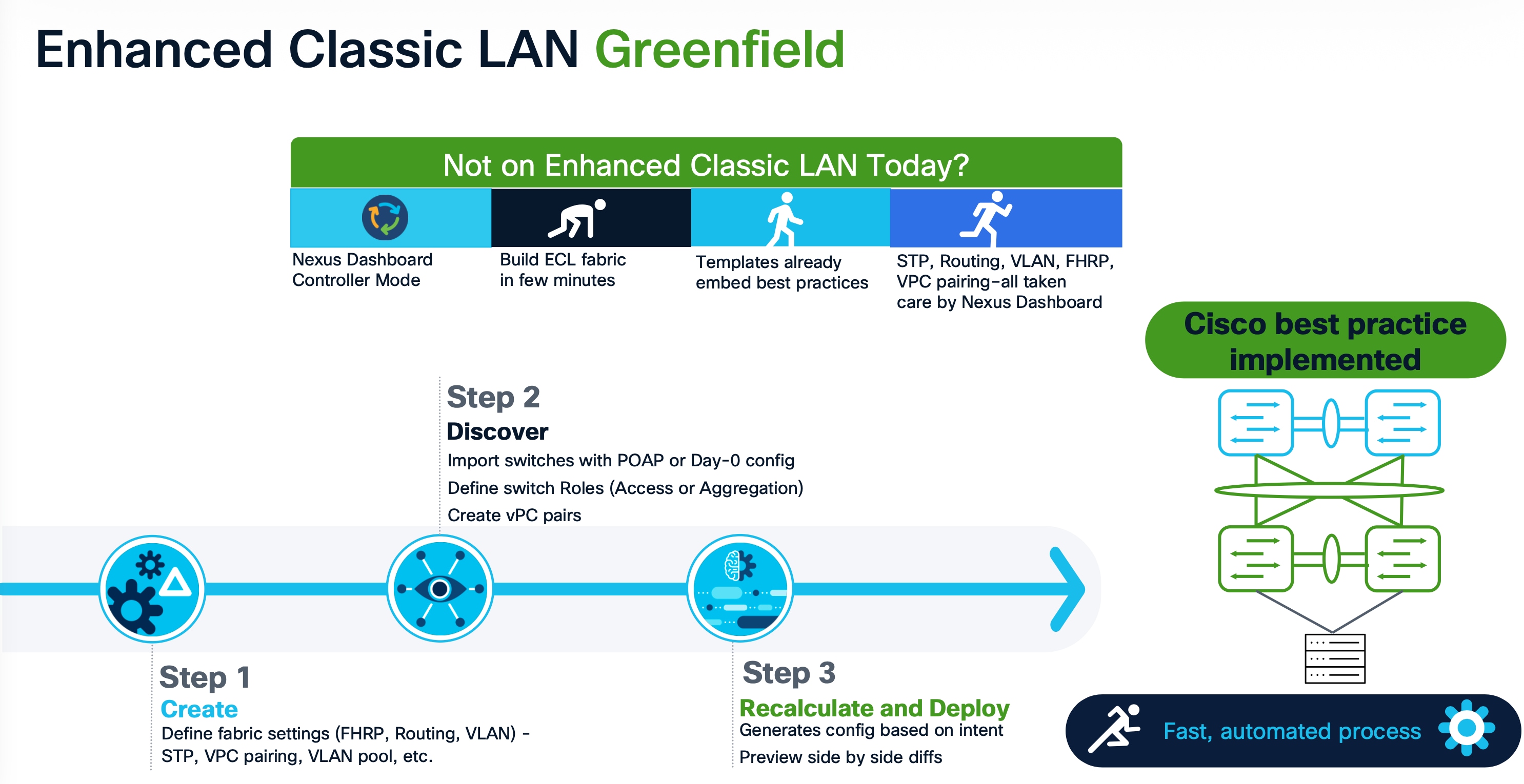
The following list contains examples of protocols that Enhanced Classic LAN greenfield provisions (as of the ND 4.1 release), keeping in mind Cisco recommended best practices and configurations for 3-Tier Access-Aggregation-Core and Layer 2/Layer 3 demarcation at Aggregation or Collapsed Core:
1. Routing protocols between Aggregation and Core/Edge layers: eBGP, OSPF, None
You can use the None option when:
· No routing is present (Access and Aggregation are both Layer 2)
· Using static routing/IS-IS between the Aggregation and Core/Edge layers (you can configure this using ND policies)
2. Spanning tree (with the Aggregation layer as bridge and root): RVPST+, MST, Unmanaged
3. FHRP (at the Aggregation layer): HSRP, VRRP, VRRPv3, None
You can use the None option when both the Access and Aggregation layers are Layer 2.
4. One-click vPC pairing: Between Aggregation pairs, between Access pairs, B2B vPC between Access and Aggregation (you can use the auto-pairing option)
ND’s Enhanced Classic LAN template needs a few inputs from the user to learn their intent. At the time of fabric creation, the user must select the protocols of choice or stick with the default. Customizations for each protocol are possible under Fabric Settings. Once the fabric has been created and the respective switches have been discovered within this fabric, ND learns the topology and how the switches are connected. The user must thereafter specify roles for each switch. After the role definition, ND pushes respective configurations on ‘Recalculate and Deploy.’ After this, all configurations can be managed from a Single Pane of Glass with the ability to roll back at a granular level with the help of the "Change Control and Rollback" feature in ND.
This document covers all the items mentioned above in the Day 0 for Classic LAN and Day 1 for Classic LAN sections.
Topologies supported for Classic LAN
Two broad categories of topologies are considered for classic Ethernet in this whitepaper. The provisioning of these topologies is discussed in later sections.
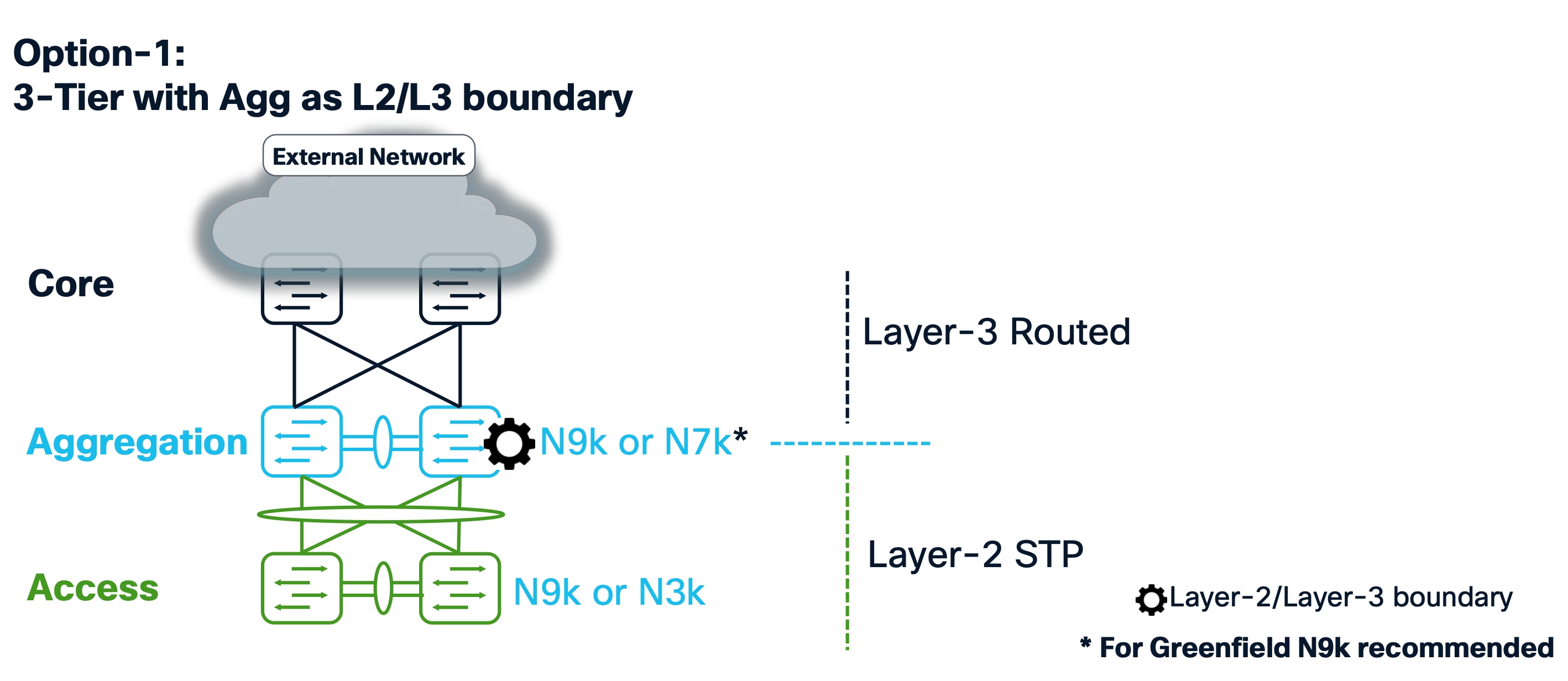
Topology 1: 3 Tier Hierarchical (Access, Aggregation, Core)
Topology 2: Collapsed Core (Access, Core)
Layer 2/Layer 3 boundary at the collapsed Aggregation/Core or Edge layer.
This is the same as topology 1, except that Core and Aggregation layers are combined into a single collapsed layer.

Topology 3: Service Node as L2/L3 boundary

Aggregation/Collapsed Core typically presents the Layer 2/Layer 3 boundary so that you can enable the appropriate SVIs with a first hop redundancy protocol (FHRP) of choice at this layer. All routed or intra-subnet traffic is forwarded through the Aggregation layer.
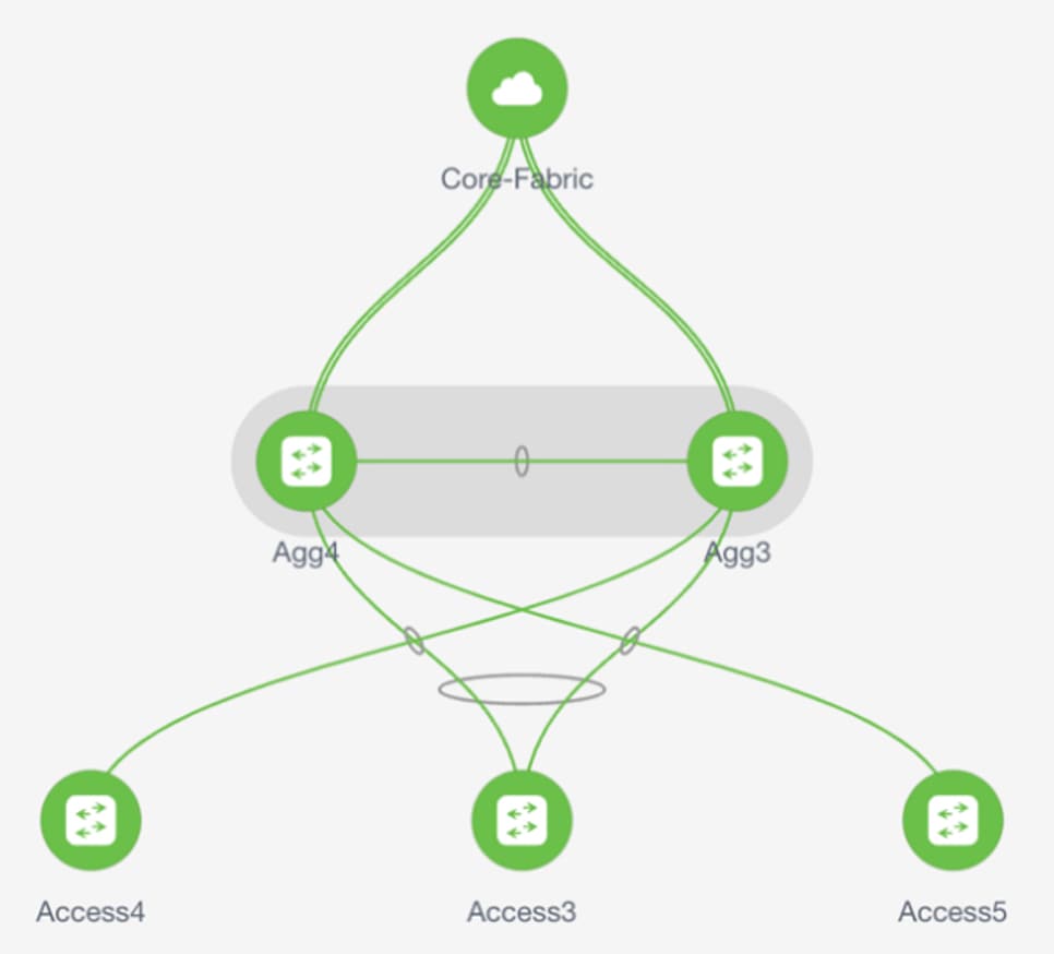
The following illustration shows the supported topologies for connectivity between the Access and Aggregation layers for a greenfield deployment: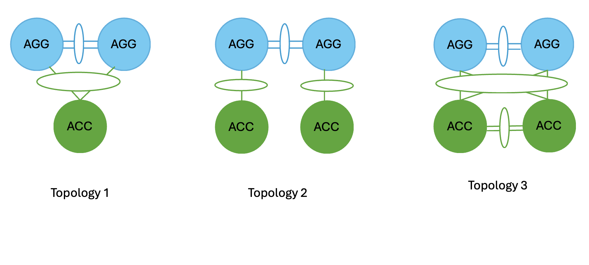
● Topology 1: vPC domain at the Aggregation layer with the same Access switch connected with a port channel to both Aggregation switches.
● Topology 2: vPC domain at the Aggregation layer with Access switches connected in “straight-through” mode to a single Aggregation switch.
● Topology-3: vPC domain at the Aggregation with back-to-back vPC connectivity to a pair of access switches.
For Brownfield deployments, we support the same above-mentioned topologies.
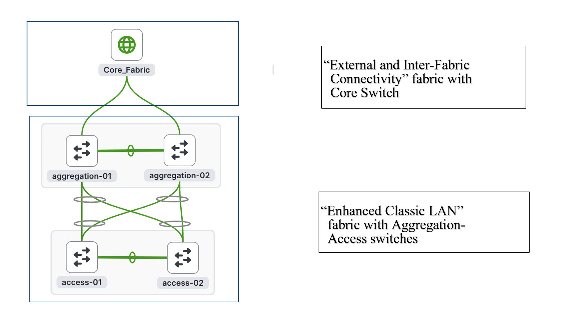
There can be several variations to the topologies based on how the switches are connected. The following figures show some of the variations:
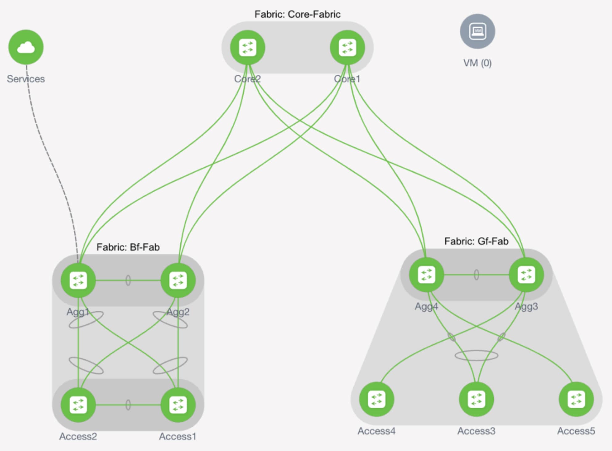
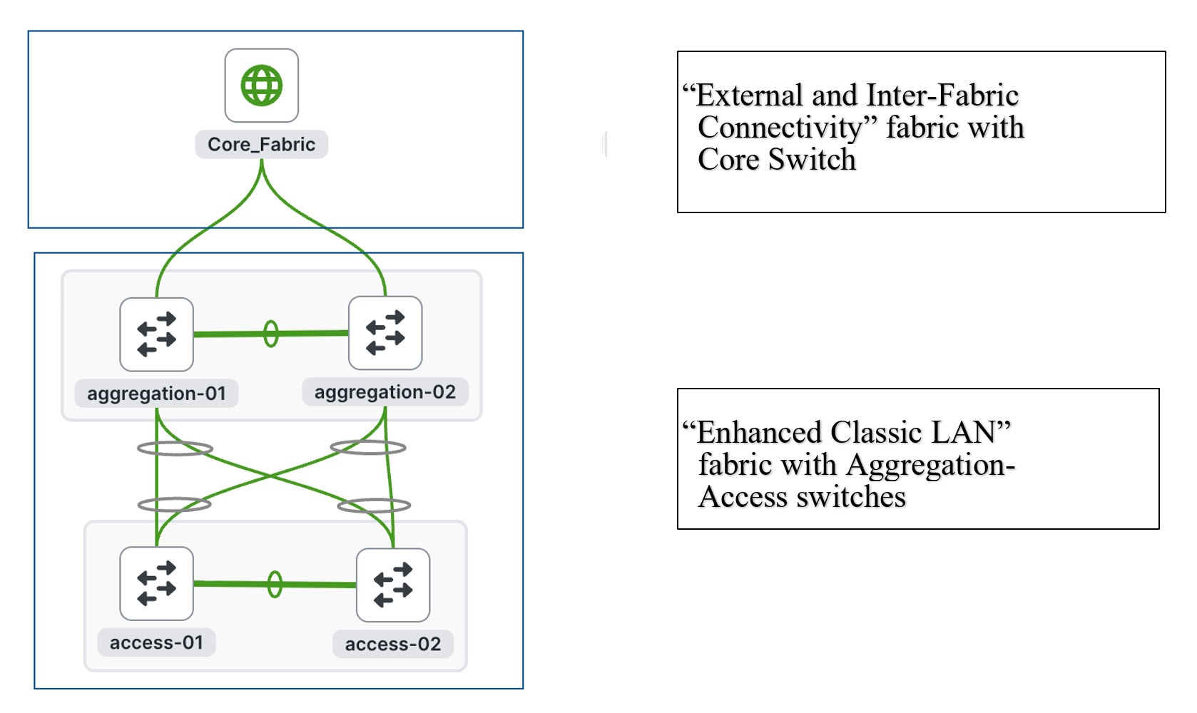
In these topologies, Access and Aggregation switches use the "Enhanced Classic LAN" fabric type in ND. For Core/Edge, you must use the External and Inter-fabric connectivity fabric type.
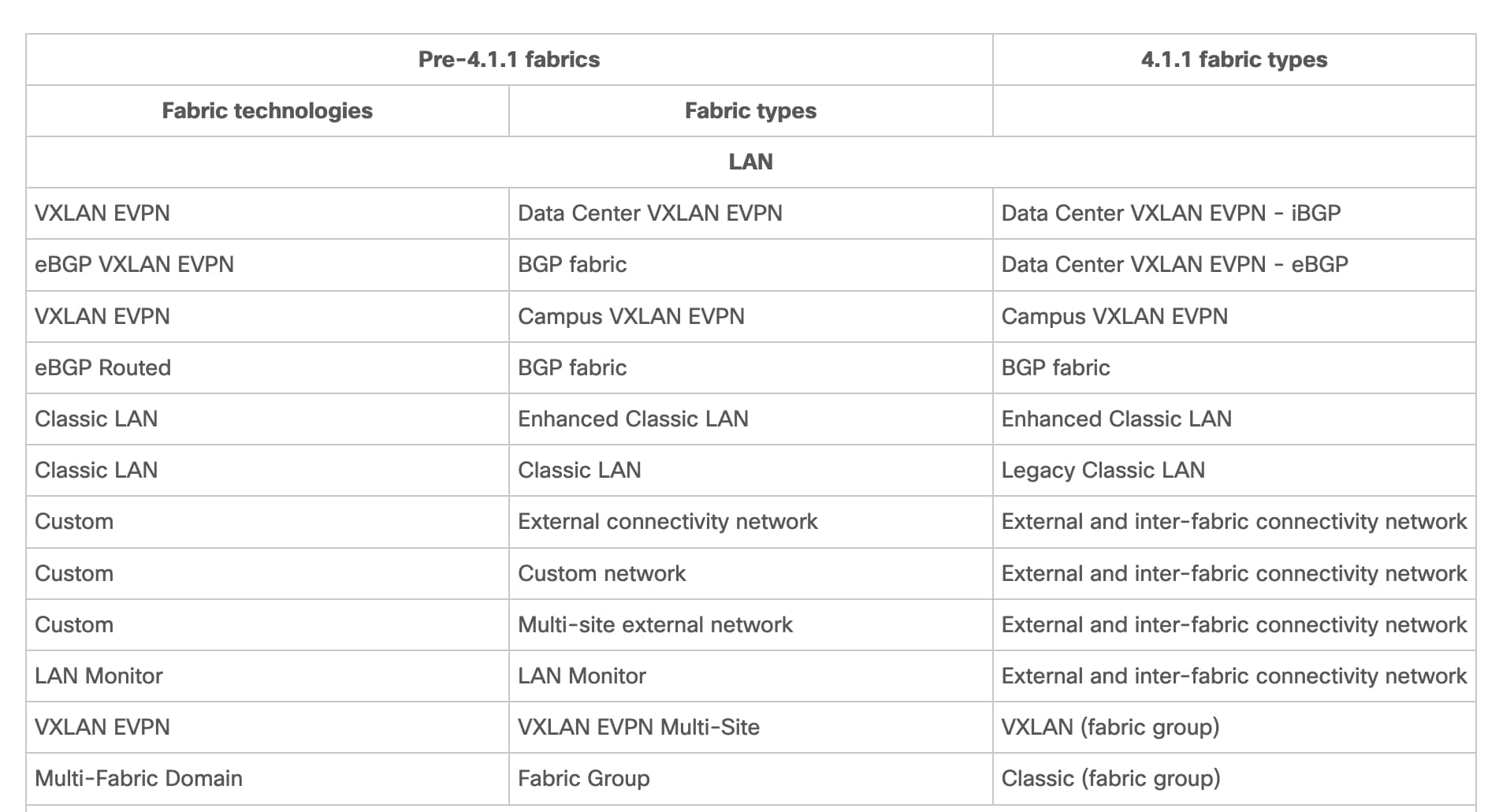
Note: Starting in the 4.1 release “External Connectivity Network” has been renamed to “External and Inter-fabric connectivity.” You can refer to the table below for a complete list of changes in the Fabric names.
External Connectivity from Enhanced Classic LAN
You must have external connectivity from the data center. That is, you must have reachability for workloads that are part of the data center fabric that can communicate with external network resources over WAN/backbone services. Use the VRF-Lite connectivity option between Aggregation devices and the Core/Edge router for connecting the fabric to an external Layer 3 domain for north-south traffic communication and for interconnecting several fabrics. Regarding Core and Edge, ND supports both roles as external connections/exit points of Enhanced Classic LAN networks. These Core and Edge platforms are placed and supported in the External and inter-fabric connectivity network fabric type. ND supports the auto Virtual Routing and Forwarding-Lite (VRF-Lite) option for Nexus and Non-Nexus devices.
Note: VRF-Lite assumes the existence of multiple VRF instances, but in classic networks that may not be the case. ND supports the existence of a single VRF instance as well.
Core or Edge roles are identical, and they have no functionality differences. You can use these roles interchangeably for external connectivity.
Guidelines and Limitations for Enhanced Classic LAN
The following guidelines and limitations apply:
· Support for greenfield and brownfield.
· Supports IPv4 and IPv6 for switch discovery as well as for VRF-Lite.
· Support for FEX, Nexus 7000, 7700, and Nexus 3000, 9000 platforms.
· You must create a vPC at the Aggregation Layer.
· Support for multiple Aggregation pairs with no overlapping VLANs as of ND 12.1.3.
· Support for interface groups, multi-attach/detach, quick attach/detach, and shared policies for switches.
· Support for change control and rollback.
· If Core/Edge are Nexus platforms, ND auto-generates VRF-Lite and routing configurations between Aggregation and Core/Edge. Manual VRF-Lite is also supported. For non-nexus devices (Cisco IOS-XE, IOS-XR), follow VRF-Lite as documented in the VRF Lite between a Cisco Nexus 9000-based border and a non-Nexus device. The document is for VxLAN EVPN fabric, but the steps remain the same for Enhanced Classic LAN
· Brownfield with multiple Aggregation vPC pairs in the same Enhanced Classic LAN fabric is not supported as of release 4.1.1.
· No support for in-band management and in-band power-on auto-provisioning (POAP) devices of the Enhanced Classic LAN fabric type.
For configuration information on the listed features, see the Editing Classic LAN Fabric Settings article.
Hardware and Software Recommendations
To use Enhanced Classic LAN, we recommend that you use Cisco Nexus Dashboard release 4.1.1.
Enhanced Classic LAN supports the Cisco Nexus 2000, 7000, 7700, 3000 and 9000 platforms.
At the Access layer, we recommend Cisco Nexus 3000 and 9000 platforms. We recommend the Cisco Nexus 3000, 9000, 7000, and 7700 platforms at the Aggregation and Core layer. We do not require any specific platforms per layer.
For the models of Cisco Nexus platforms and Cisco NX-OS software supported in ND release 4.1.1, see the Nexus Dashboard Capacity Planning
You must meet the following requirements to start provisioning Classic Ethernet networks:
● You must have at least one Cisco Nexus Dashboard cluster and a healthy ND service before you can perform the other operations/setup steps.
● Cisco Nexus Dashboard (virtual or physical) nodes to form a cluster.
◦ For the sizing guide for the number of nodes per form factor and supported scale, see the Nexus Dashboard Capacity PlanningNexus Dashboard Capacity Planning.
◦ Interfaces on both data and management networks can be either Layer 2 or Layer 3 adjacent.
◦ All new Nexus Dashboard deployments must have the management network and data network in different subnets.
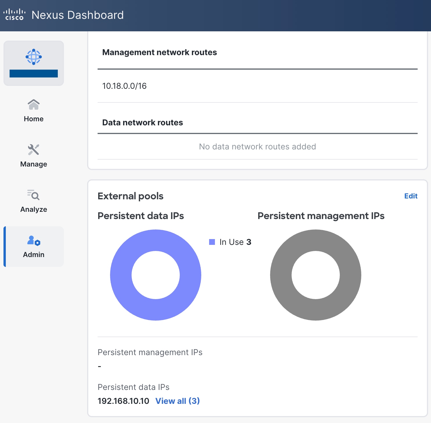
◦ You must use persistent data IP addresses to bring up the cluster, so you must allocate a certain number of persistent IP addresses depending on your configuration. Please refer to Nexus Dashboard persistent IP addressesNexus Dashboard persistent IP addresses
◦ For more information on Network Pre-requisites, see the Cisco Nexus Dashboard Deployment and Upgrade Guide, Release 4.1.xCisco Nexus Dashboard Deployment and Upgrade Guide, Release 4.1.x
● Reachability between the ND service and the switches to be managed.
◦ Classic LAN only supports out-of-band (OOB) management of switches. You must decide if you want to manage your switchesswitches OOB using the Nexus Dashboard management or data interface.
◦ Define appropriate routes for the reachability of the switches from the Nexus Dashboard cluster in Nexus Dashboard under Admin-> System Settings-> GeneralAdmin-> System Settings-> General. Define external service pools for SNMP and POAP over management or data subnet.
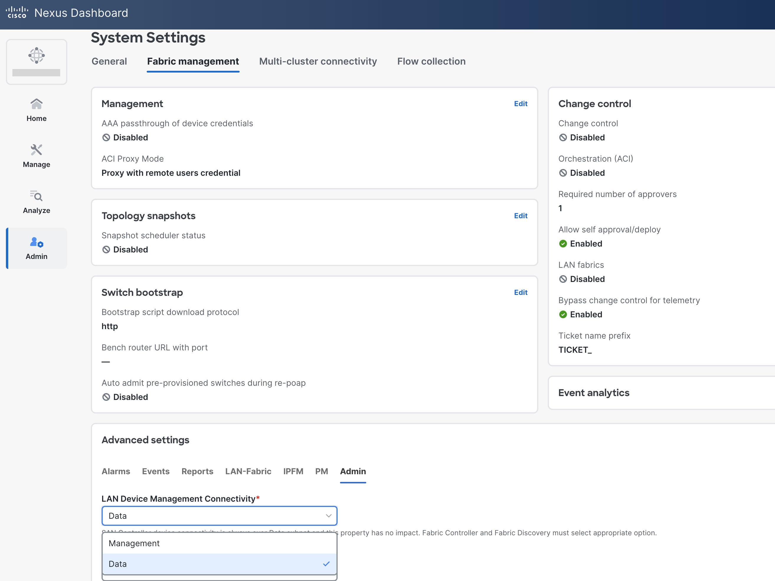
◦ When you navigate to System Settings-> Fabric management, in Advanced settings, "LAN Device Management Connectivity" in the AdminAdmin tab is set to "Data " by default. If you use the default settings, you must spawn external IP addresses associated with the Nexus Dashboard data subnet, and you can establish that connectivity between the Nexus Dashboard data interface and the mgmt0 interfaces of the switches. You do not need any static routes for this, as ND uses the default route associated with the data interface by default if that the Nexus Dashboard Data interface is not in the same subnet as the mgmt0 interfaces of the switches.
◦ If you change the setting to "Management" you must spawn external IP addresses associated with the Nexus Dashboard Management subnet and ensure that Nexus Dashboard uses the management interface to communicate with the mgmt0 interfaces of the switches. You might need to add static routes that are associated with the Nexus Dashboard Management interface. You do not need to add these routes only if the Nexus Dashboard Management interface is deployed in the same subnet of the mgmt0 interfaces of the switches.
◦ To change the default option, navigate to the "LAN Device Management Connectivity" option in ND, which is found under to System Settings-> Fabric management -> Advanced settings (Same Page, bottom half) ->Admin tab. These settings are discussed in the Cisco Nexus Dashboard Fabric Controller Deployment GuideCisco Nexus Dashboard Fabric Controller Deployment Guide.
● Fabric Type to be used
◦ Enhanced Classic LAN
● Switches and roles that can be managed in Enhanced Classic LAN Fabric
◦ Cisco Nexus 2000, 3000, 7000, 7700, and 9000.
◦ Enhanced Classic LAN supports only the Access and Aggregation roles. For Core/Edge, you must use the external and inter-fabric connectivity fabric type.
This section discusses day 0 for classic LAN topology. For Collapsed Core topologies, see the Step 4: Define the Roles section.
This section first discusses the steps for configuring a fabric consisting of the Access and Aggregation layers, then discusses the steps for creating a fabric for the Core layer.
Note: All features highlighted for the Core layer are also supported for the Edge role.
There are two separate fabrics because typical deployments comprise a shared Core layer. The Core routers reside in a separate fabric shared by fabrics with the Access-Aggregation switches.
For the Access and Aggregation Layers
The overall process for configuring the Access and Aggregation layers is as follows:
2. Discover the switches in the fabric.
● Greenfield ImportGreenfield Import
● Brownfield ImportBrownfield Import
3. Bootstrap the switches (Power-On Auto-Provisioning).
The following sections discuss each of the steps in detail. The screenshots of pending configurations are examples of a single Access, Aggregation, and Core layer for explanatory purposes and do not include all the pairs that are in the topology.
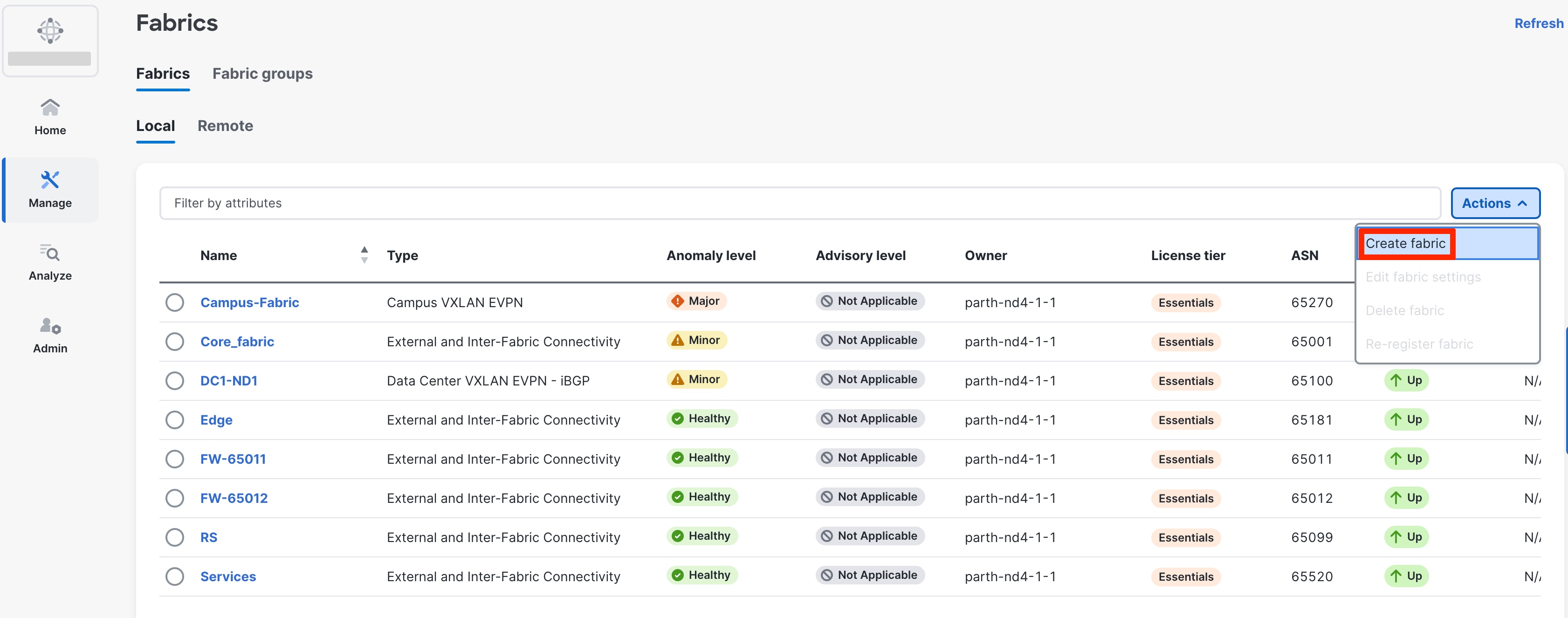
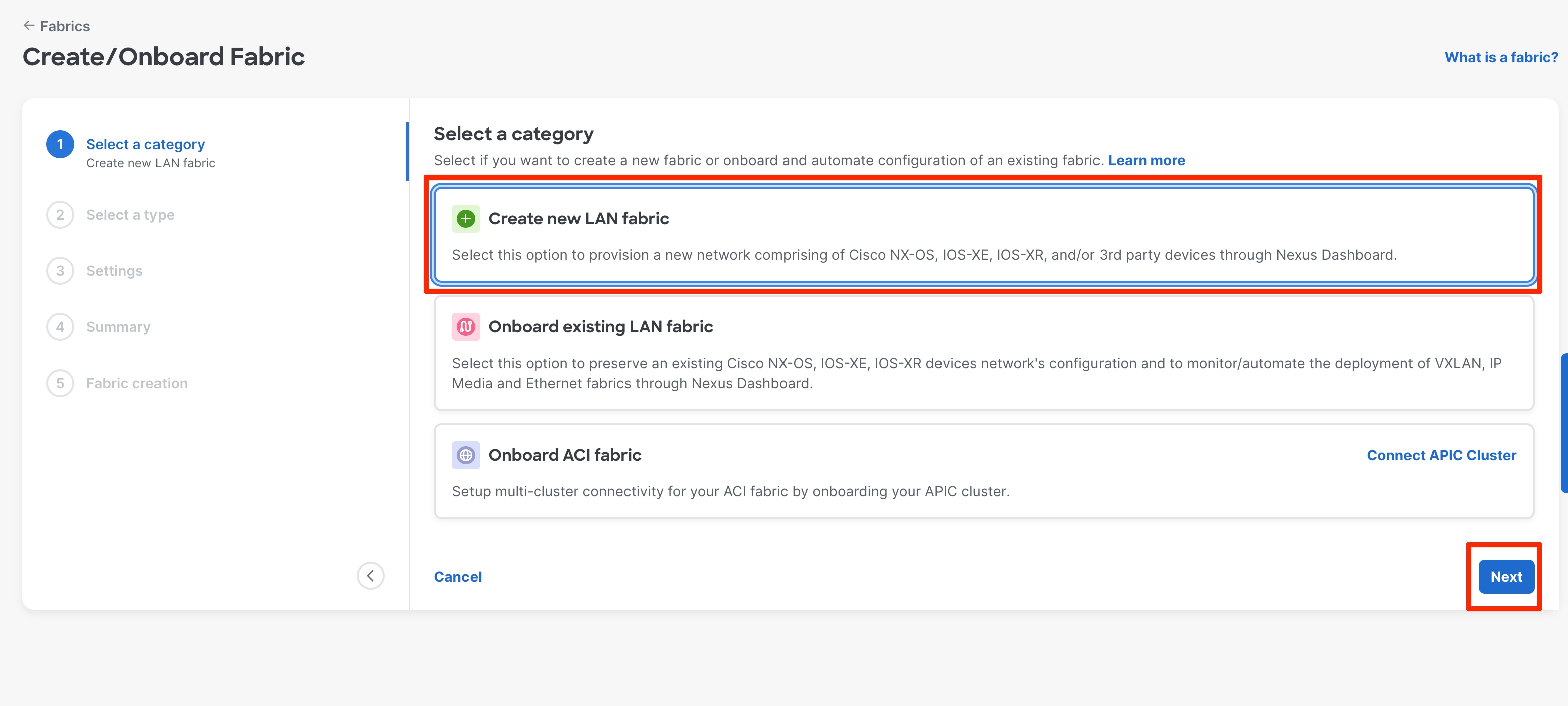
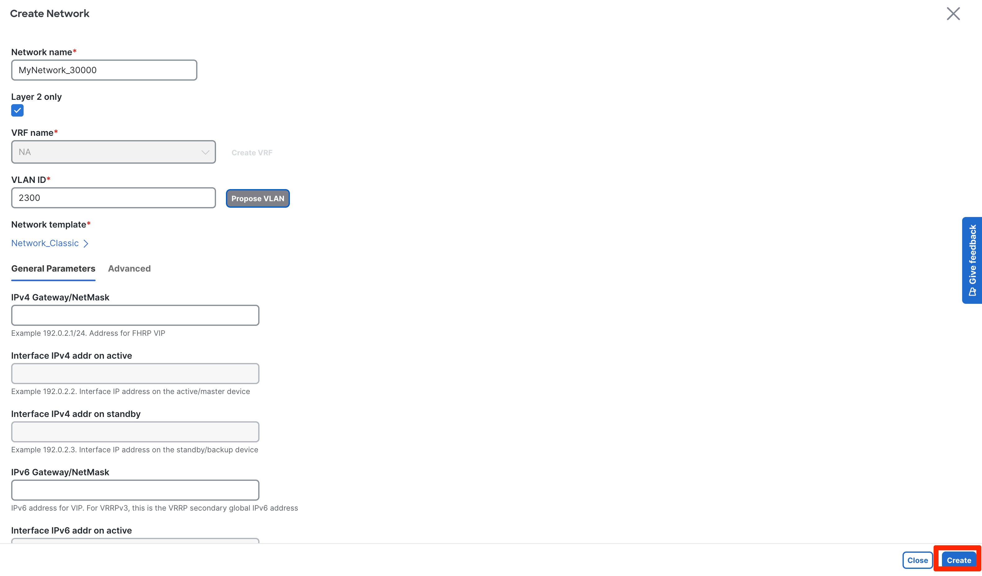
◦ The first step is to create a fabric. Go to Manage -> Fabrics-> Action-> Create Fabric.
◦ Next step is to select a category.
◦ For Greenfield deployment select “Create new LAN fabric “
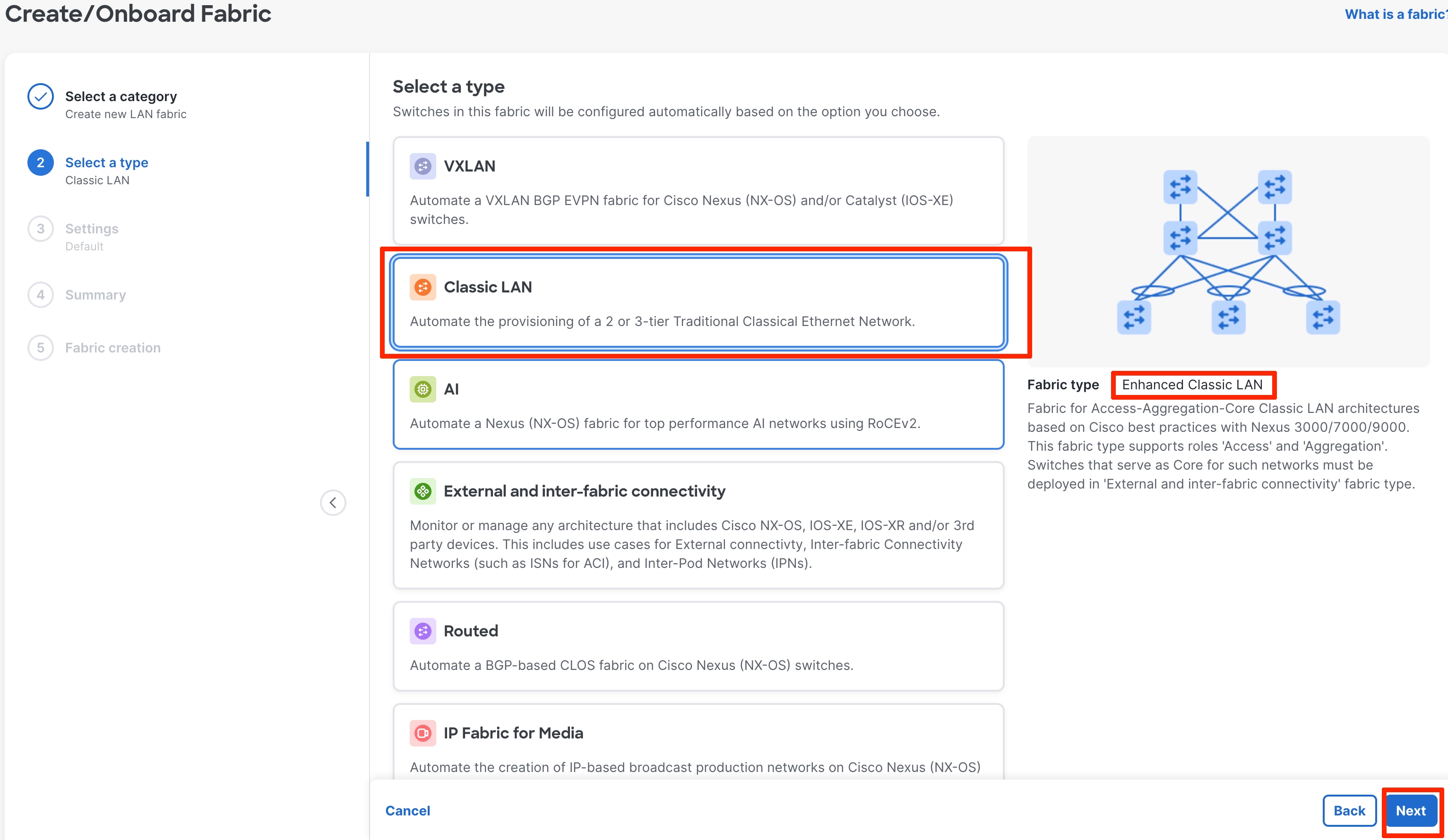
Select Classic LAN. The fabric type shows the “Enhanced classic LAN.”
“Enhanced Classic” template is for Access and Aggregation switches. The fabric-level template helps define parameters that apply to the respective network layers and the fabric as a whole.
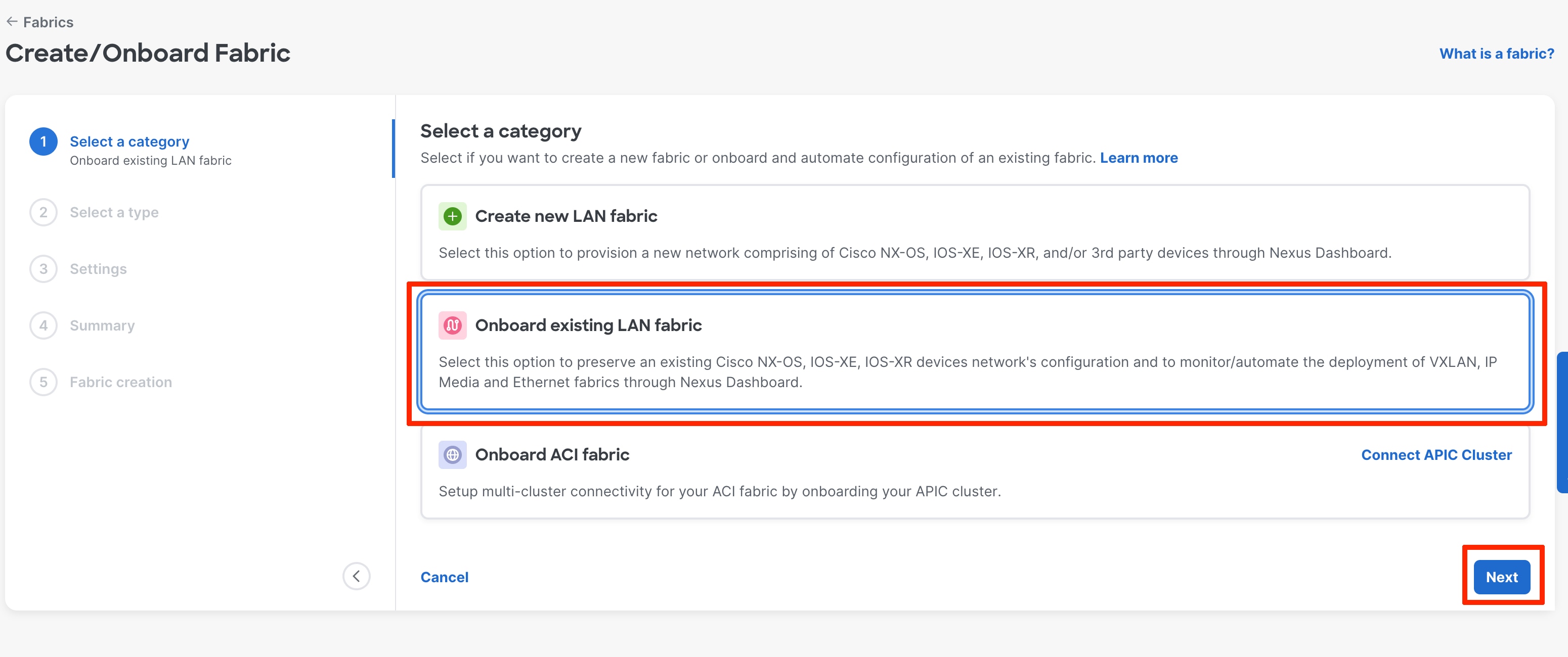
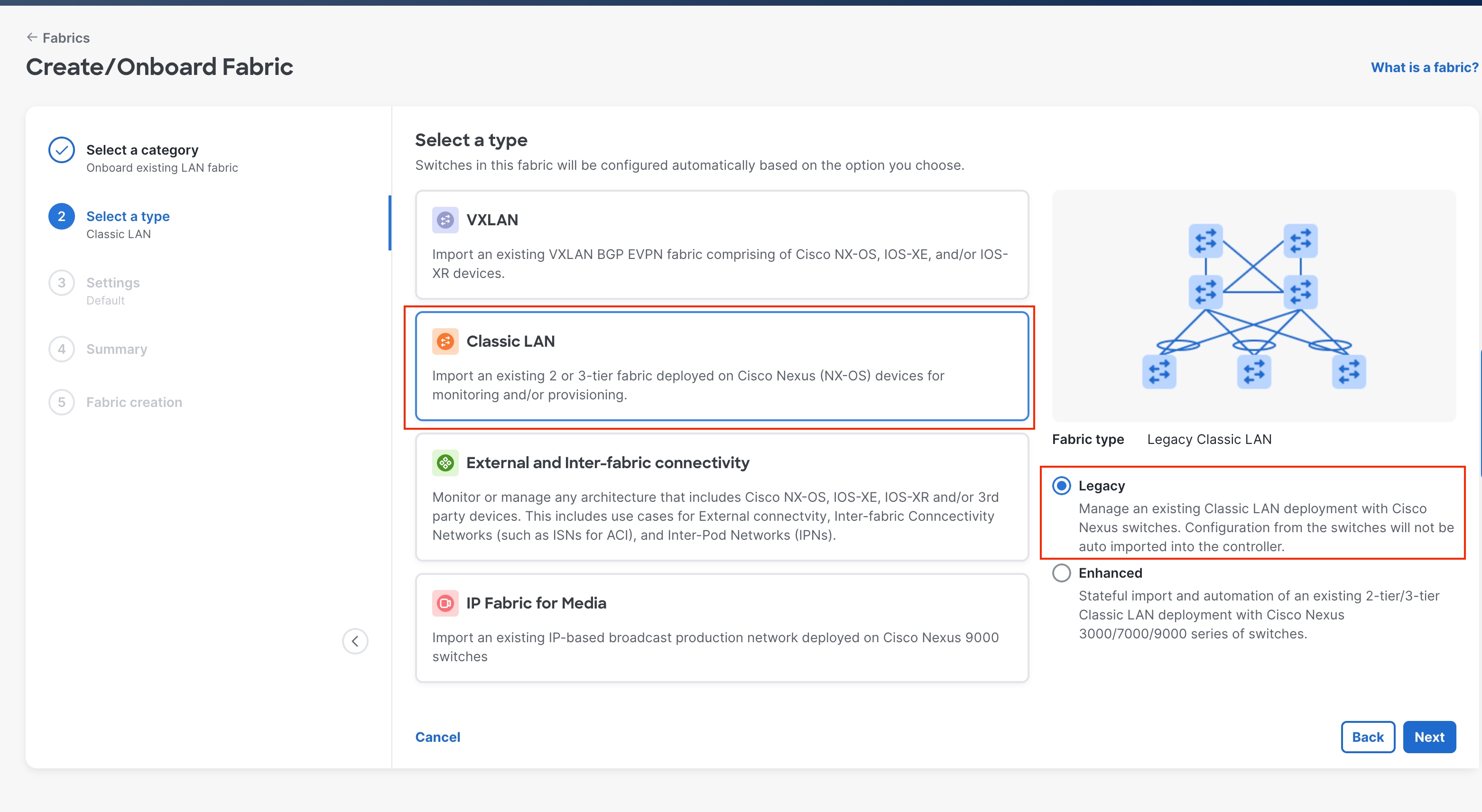
◦ For Brownfield deployment select “Onboard existing LAN fabric”
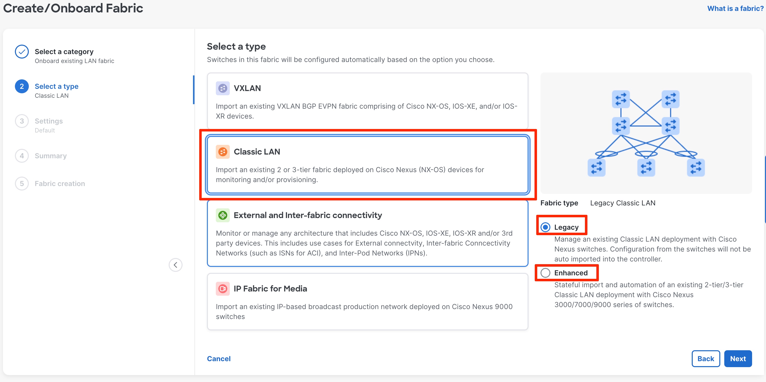
Select Classic LAN. Under this we have two options “Legacy Classic LAN” and “Enhanced Classic LAN”
Legacy Classic LAN use case is covered later in the document. For Brownfield deployment, in Enhanced Classic LAN, there is a stateful import of the configurations on ND.
After you choose the fabric template, you can optionally customize the fabric-level settings or leave them at their default values. The default values are as per Cisco best practice recommendations, and thus you should not change the values unless required.
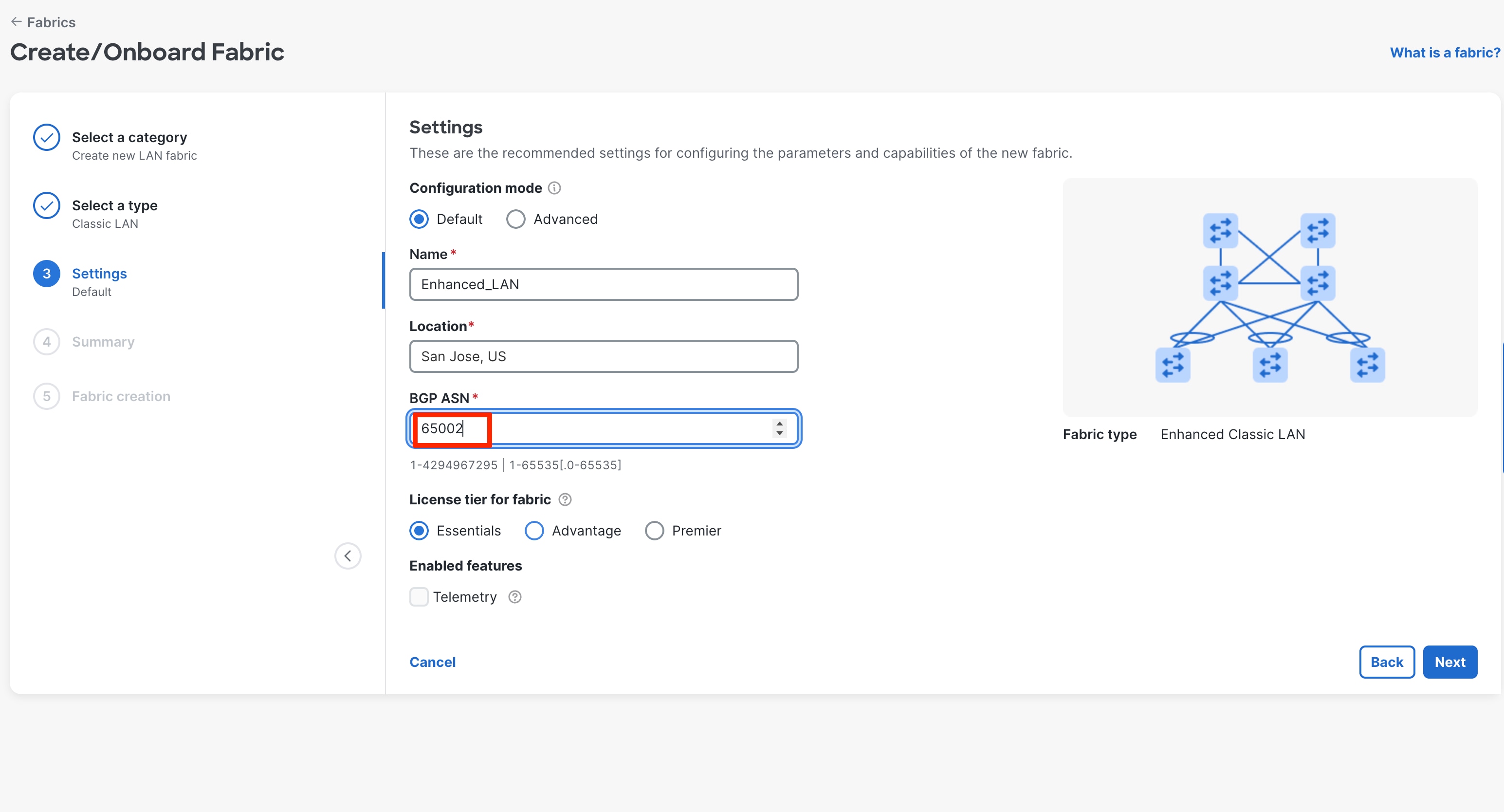
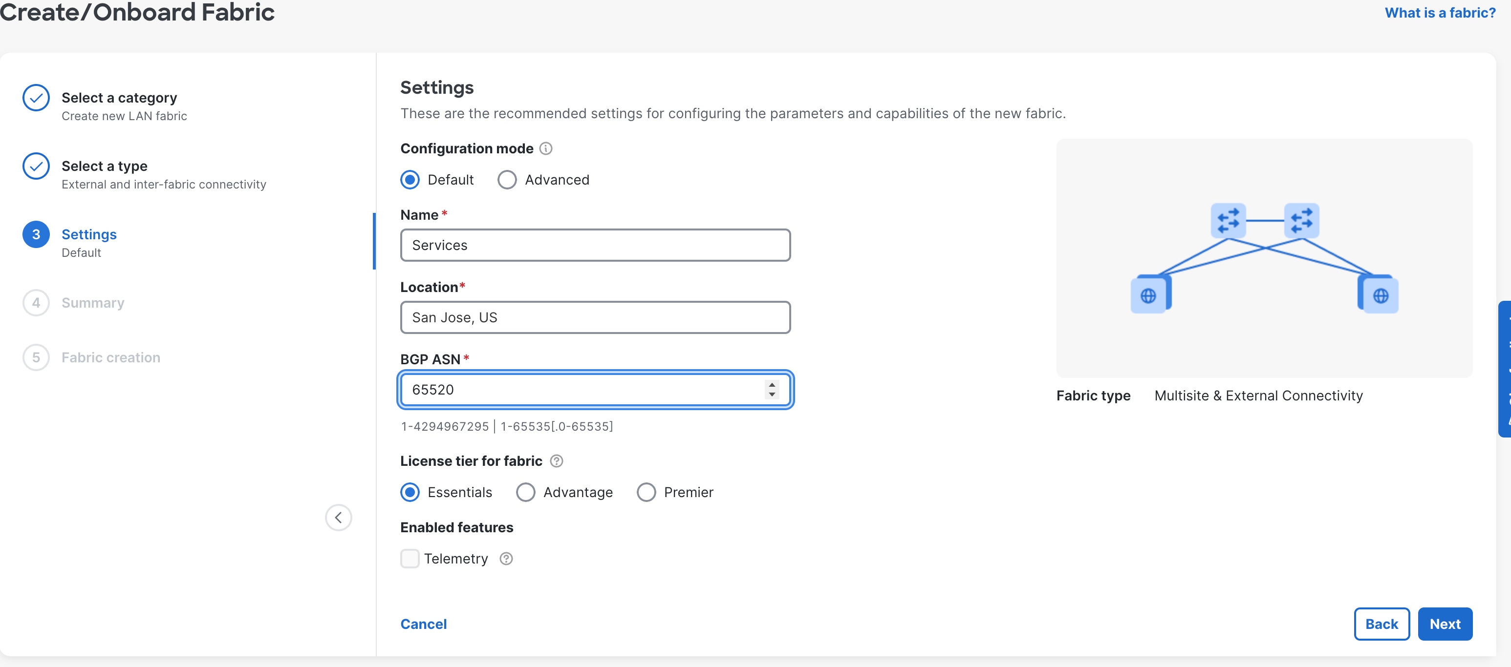
The next step is to configure Default and Advanced settings. Default mode applies recommended settings, and Advanced mode exposes all available configuration parameters.
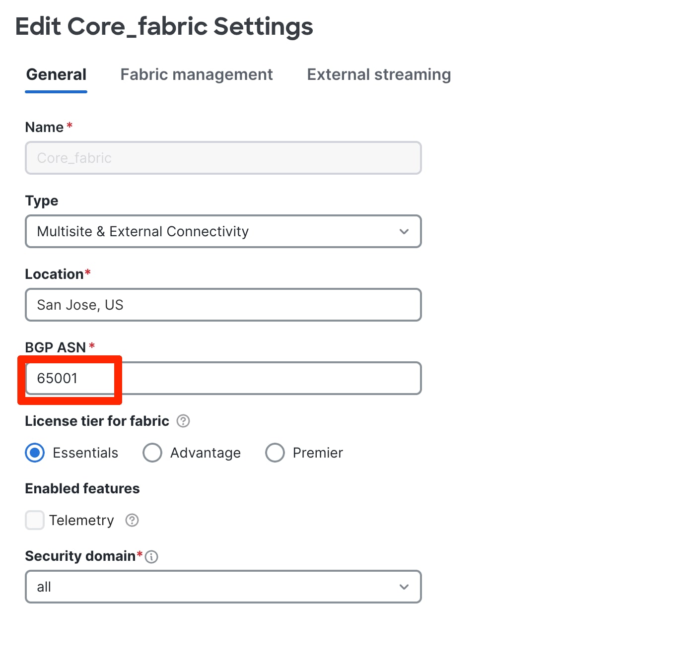
In the Default mode, following settings are mandatory:
● Fabric Name,Fabric Name, Location,Location, BGP ASNBGP ASN, License TierLicense Tier for Fabricfor Fabric and Enable/Disable Telemetry.Telemetry.
- In the default configuration Mode, you are required to enter the BGP ASN.
● If you do not use eBGP as peering protocol between Aggregation device and Core/Edge router, select the “Advanced” radio button and choose appropriate option for the VRF-Lite protocol (eBGP/OSPF/none).
● The license tier is per fabric. Clicking the “?”, gives detailed information on each of the license tier features.
● You can enable Telemetry to configure devices in the fabric to send telemetry data to a single Nexus Dashboard cluster. If the telemetry box is greyed out, it may mean that the ND cluster does not support enabling Telemetry (For example if you have a single APP node as the ND cluster). Click on the “?” to understand the pre-requisites for enabling telemetry.
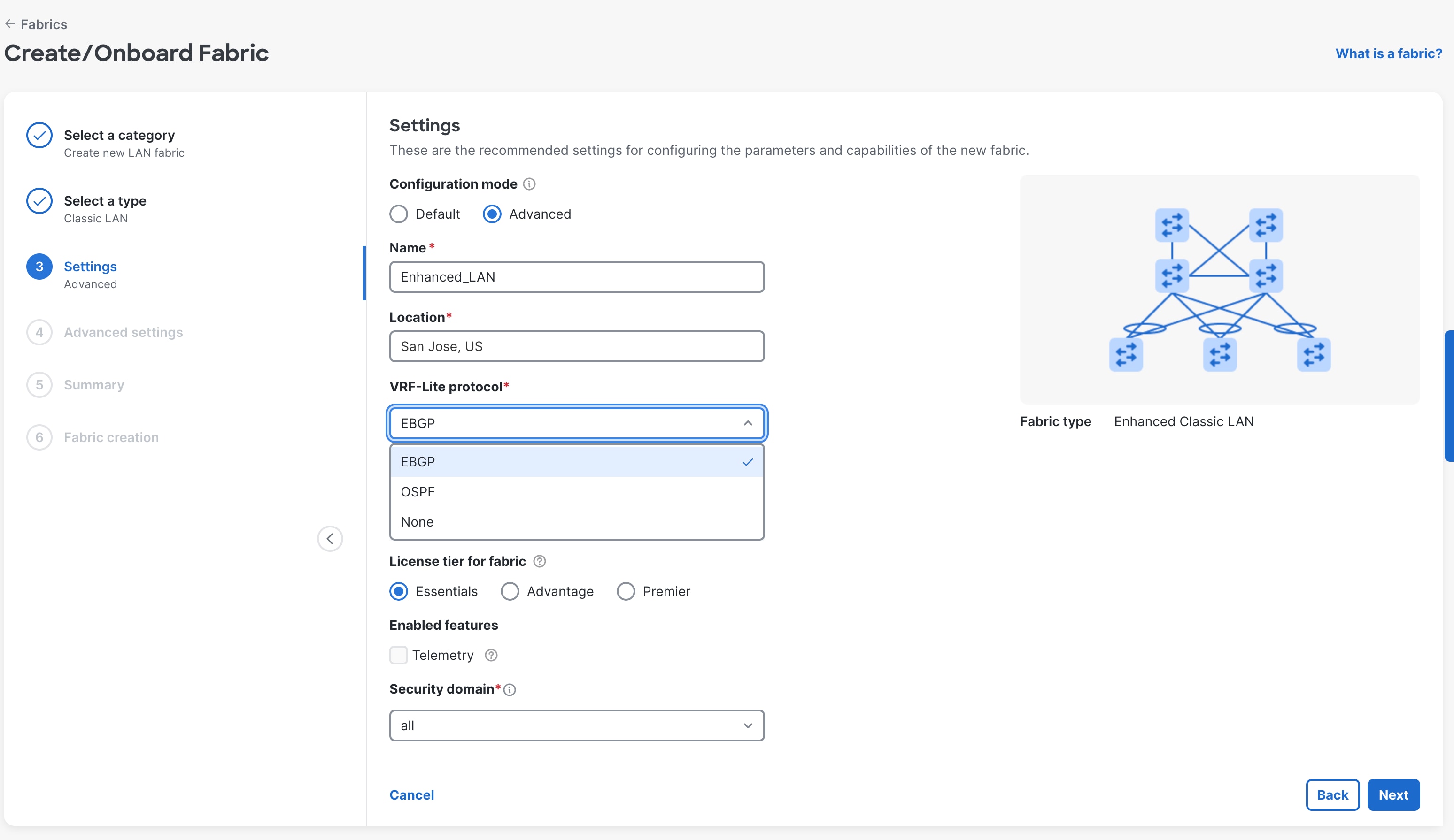
In the Advanced mode, following settings are mandatory:
Fabric Name, Location, VRF-Lite protocol, License Tier for fabric, Enable/Disable Telemetry, Security Domain
● The VRF-lite protocol VRF-lite protocol is the connectivity option between Aggregation devices and the Core/Edge router. By default, eBGP is selected.
◦ The other options are OSPF and None
● If you select OSPF, in the advanced setting (Protocols TAB on the next page) you will be required to provide OSPF Tag Tag, and Area IDArea ID when you use OSPF as a peering protocol between the Aggregation and Core layers.
● The default Security domain is “all.” You can create security domains to restrict user access for that fabric.
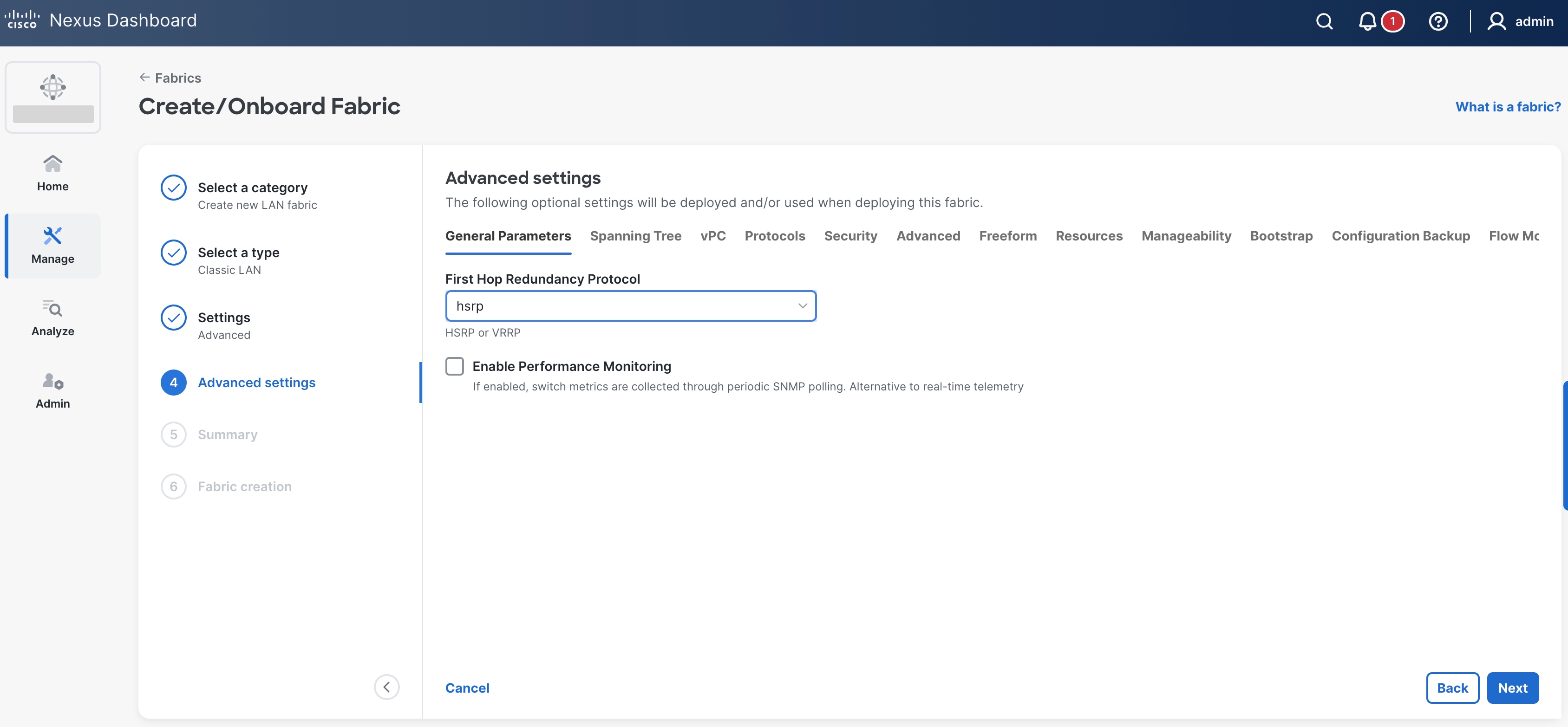
The default options for General Parameters are as follows:
● FHRP – HSRP
◦ Supported options: HSRP, VRRP, VRRP3, and None
● Enable Performance Monitoring – No
◦ This option collects SNMP-based stats, such as CPU, memory, and temperature.
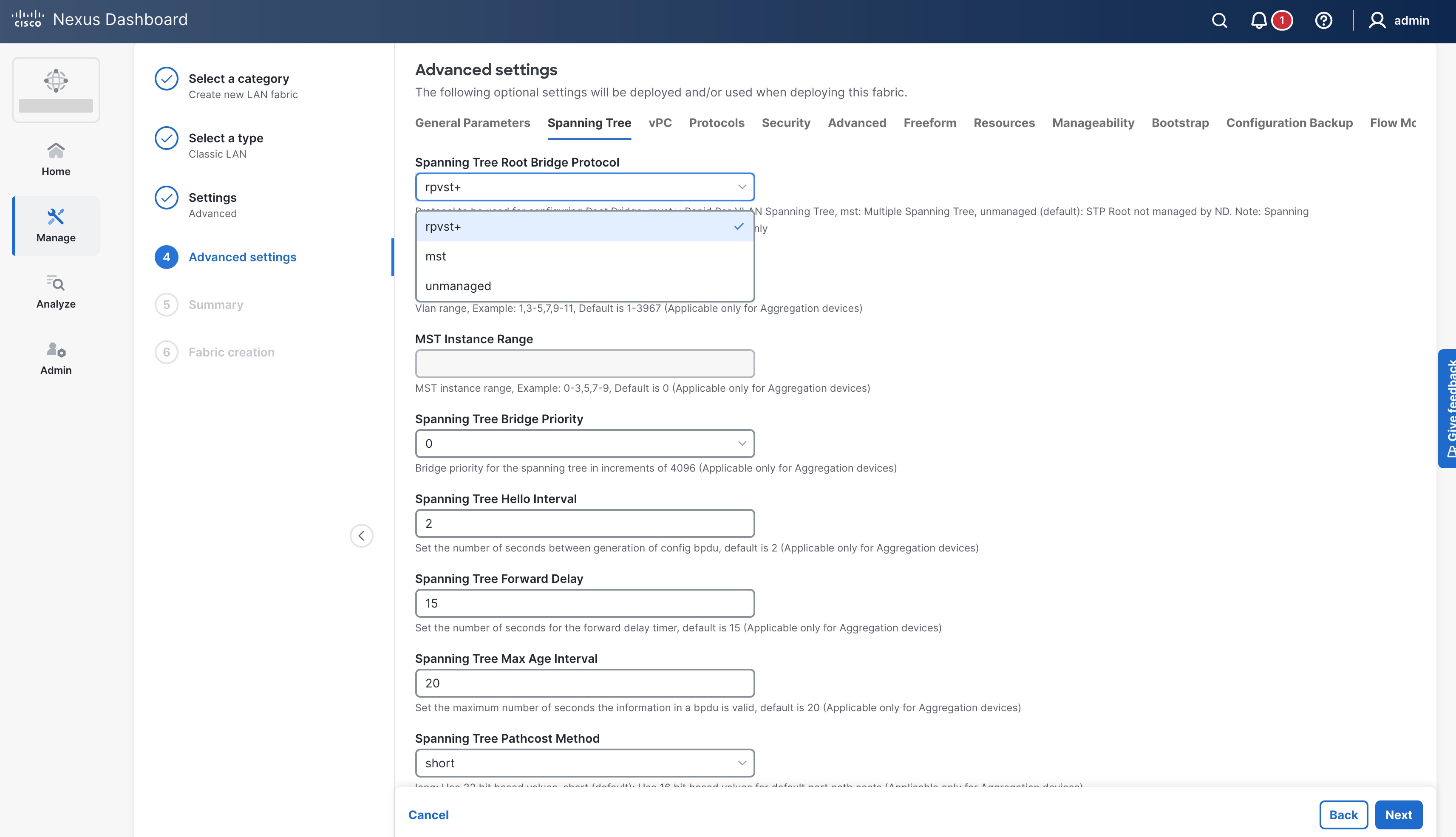
The default options for spanning tree parameters are as follows:
● Spanning Tree Protocol – RPVST+
◦ Supported options: RPVST+, MST, and Unmanaged.
All values and timers are per Cisco best practice and can be customized.
The vPC defaults in the following screenshot are per Cisco's best practices and you can customize the values:
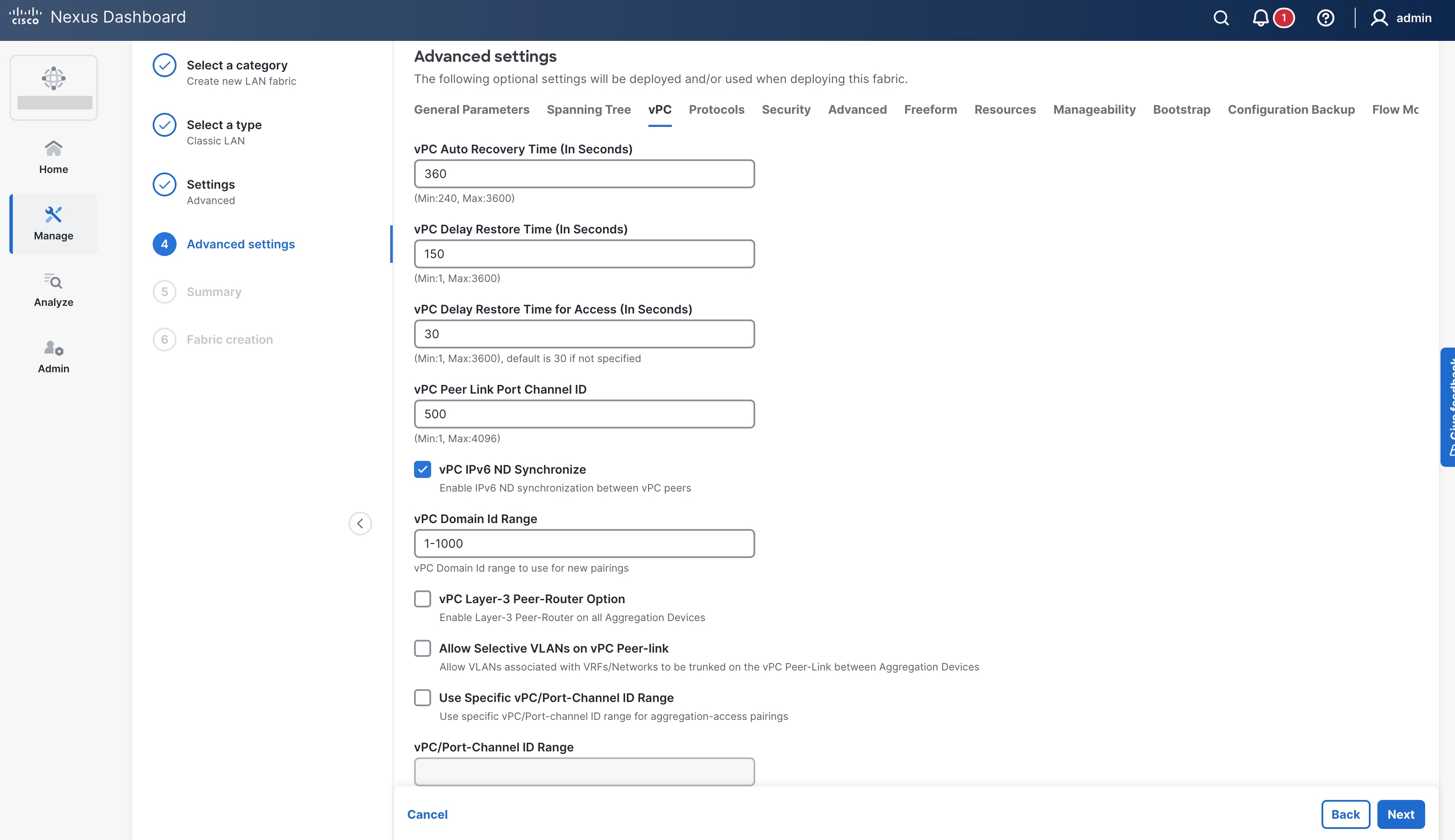
You can customize the following additional settings:
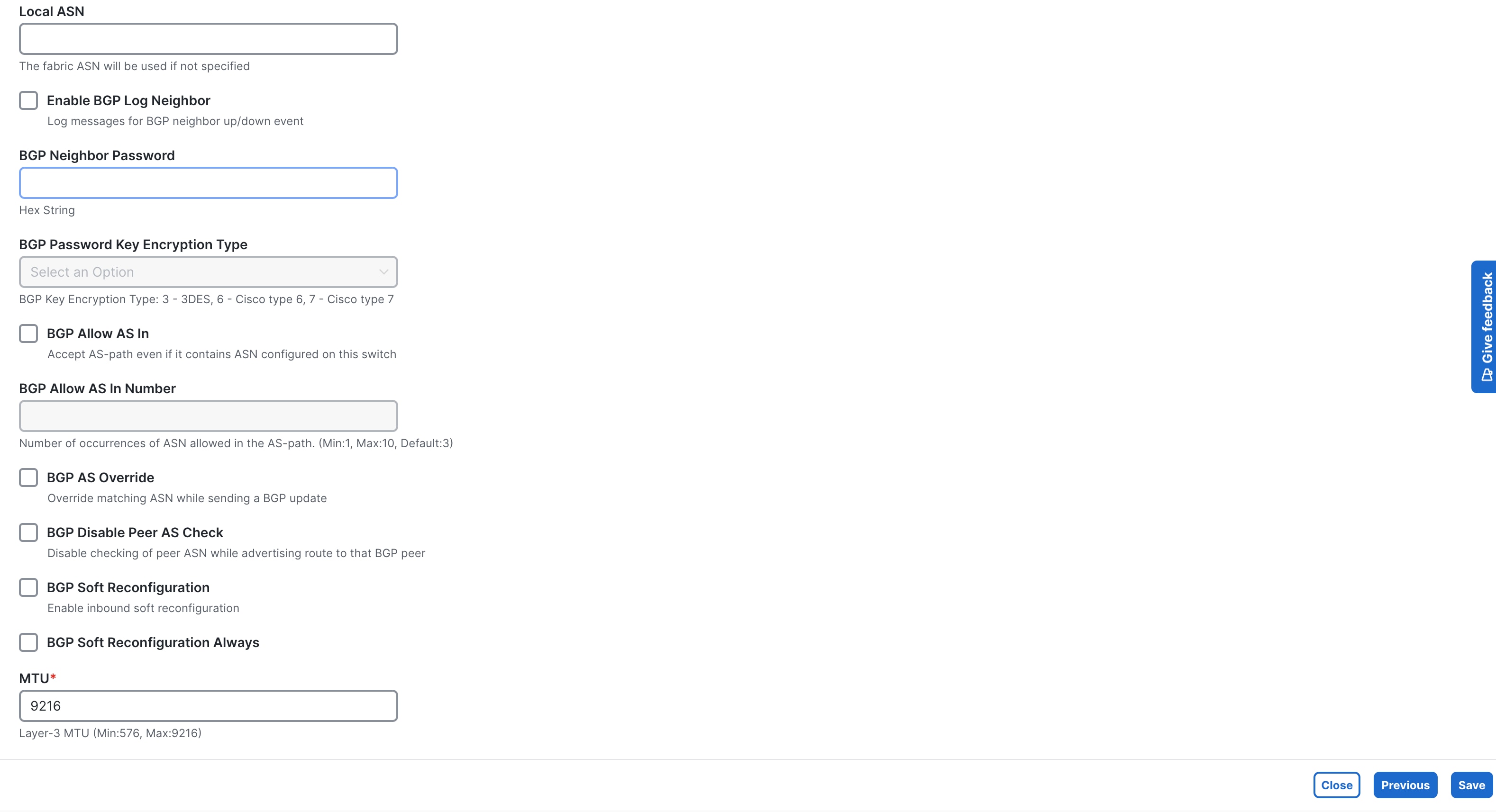
● ProtocolsProtocols for OSPF and BGP authentication
● Security Security to enable MACSec on DCI links
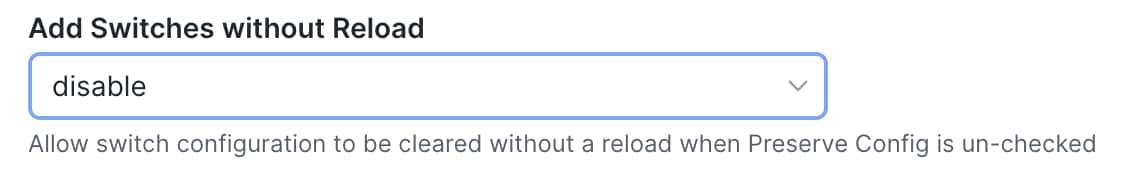
● AdvancedAdvanced for VRF and Network templates to be used for sub-operations, Layer 2 Host MTU, Power Supply Mode, CoPP profile, NXAPI, AAA IP authorization, configuring PTP settings, adding switches without reload
● Add Switches without ReloadAdd Switches without Reload to be used for greenfield deployments when the switch configuration is cleared prior to adding the switches to ND. When this option is enabled, the switches will not be reloaded after clearing the switch configuration. By default, the option is disableddisabled i.e., switches will reload after clearing the configuration. This is not applicable to Nexus 7000 switches
● Freeform Freeform for Pre and Post Interface configuration on Aggregation and Access switches.
● ResourcesResources for the default IP address and subnet ranges
● ManageabilityManageability for DNS, NTP, syslog server settings and AAA freeform config
● BootstrapBootstrap for POAP and DHCP server settings; use this option to enable POAP at a fabric level
● Configuration BackupConfiguration Backup to define the cadence of automatic fabric level backups
● Flow MonitorFlow Monitor to enable NetFlow
The Recalculate & Deploy (R&D) process auto-generates the appropriate best practice configurations for both the Access and Aggregation layers based on the above settings.
Note: After you create a fabric, you cannot edit the values for Fabric Name, First Hop Redundancy Protocol, and VRF Lite Agg-Core or Collapsed Core-WAN Peering Protocol Options.
Step 2: Discover the Switches in the Fabric
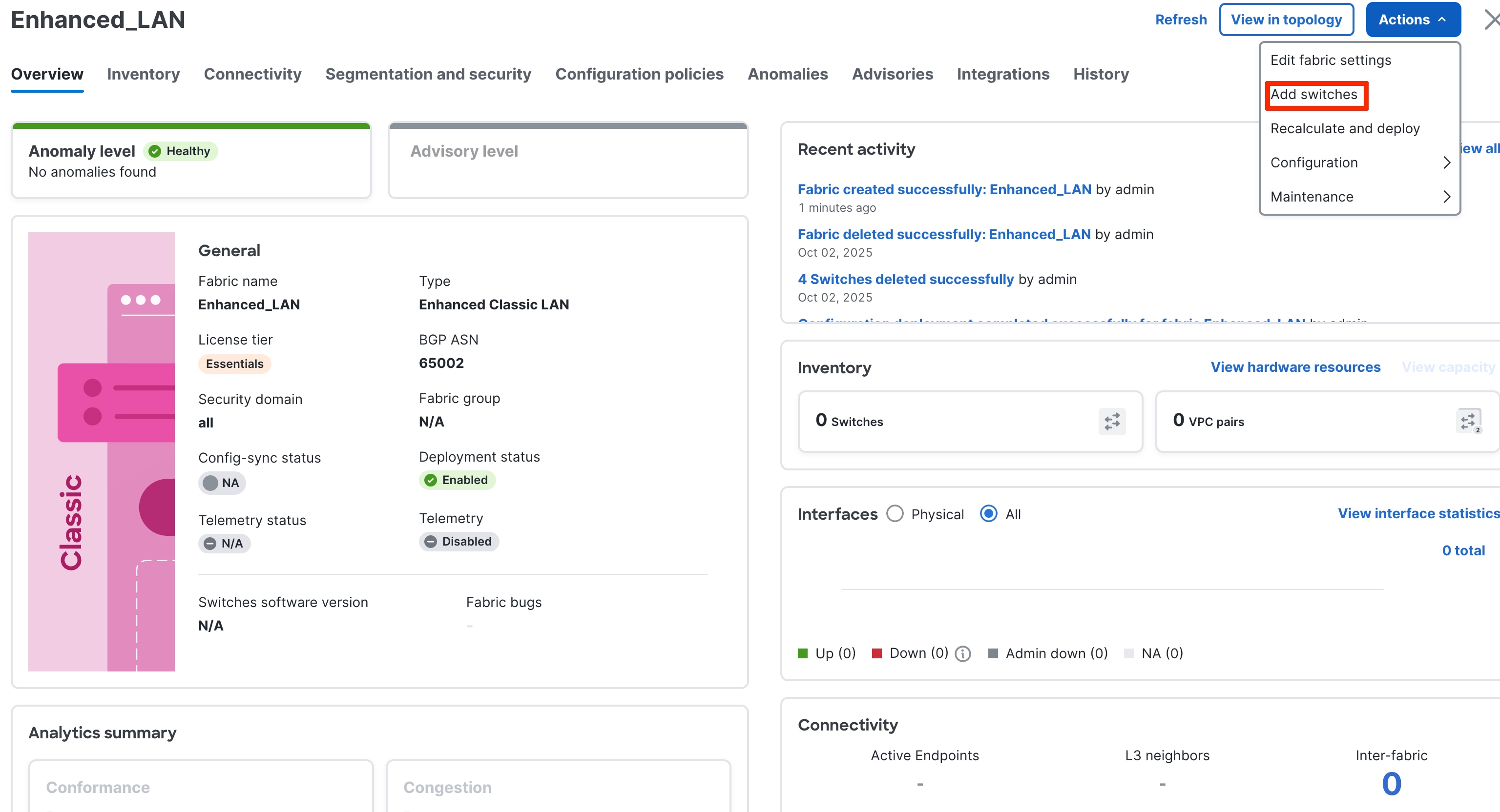
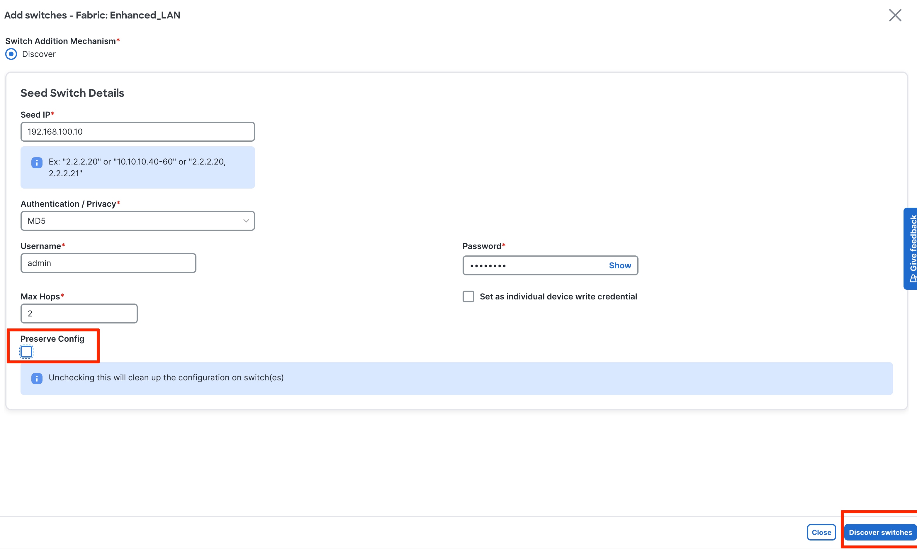
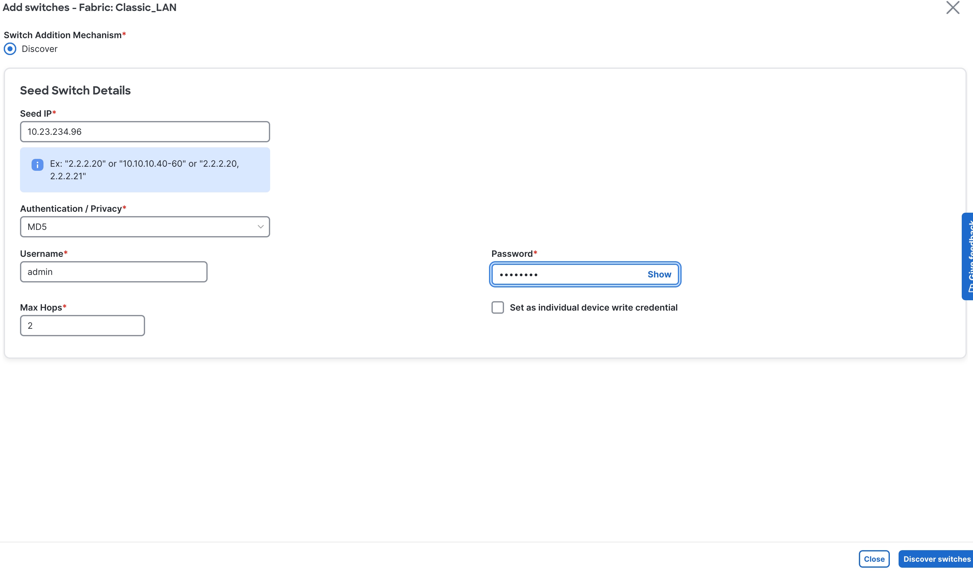
After you create the fabric, you can import the switches using Seed IP and Credentials. This can be done by clicking on the fabric and going to the “Actions” tab. Make sure reachability exists between ND and these switches. The seed IP address must be the management IP address of one of the switches. This fabric type supports only Out-of-Band management of the switches as of ND release 4.1.1.
Greenfield Import (New fabric)
If you do not put a check in the Preserve Config box, ND performs a greenfield import. ND erases all existing configurations except the management IP address, default gateway, and boot variables, and pushes a fresh configuration. You can then manage all switches from scratch.
In the case of a greenfield addition of Cisco Nexus 9000 switches, by default ND learns the basic intent from the switch and performs a write erase and reload followed by restoring only the basic intent on that switch. For Cisco Nexus 7000 switches, given that they are VDC-based, the greenfield addition follows a different path. Specifically, because ND does not support VDC POAP, ND performs the clean-up on the Nexus 7000 device without a reload. You can disable the reload for Nexus 9000 switches in the Fabric settings under the Advanced tab (“Add Switches without Reload” option discussed before).
Brownfield Import (Existing Deployment)
If you put a check in the Preserve Config box, ND performs a brownfield import, which preserves all existing configurations.
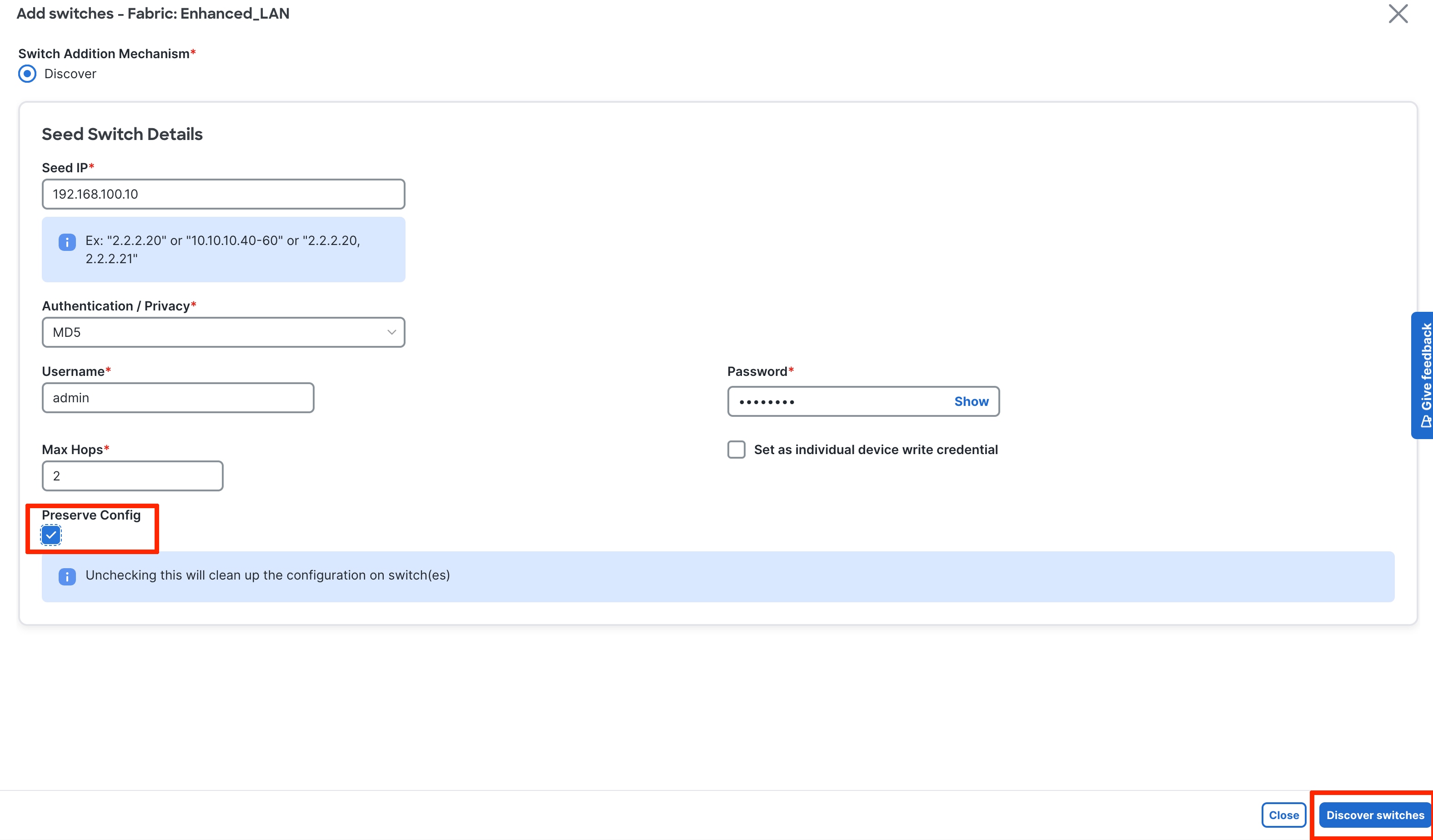
In Enhanced Classic LAN with brownfield import, ND preserves all configurations on the switches. Thereafter, ND incrementally manages the switches. The prerequisite is that the fabric of imported switches must be fully functional with configurations as per Cisco best practices. If not, the brownfield import fails, and ND generates relevant error messages to guide the user.
When you perform a brownfield import on ND, adhere to Cisco's best practices and recommendations before the import. In addition, you must meet the following prerequisites:
● No support for brownfield of fabric path-based infrastructures
● Enhanced Classic LAN can support 3-tier and 2-tier with the Collapsed Core layer
● You must have vPCs at the Aggregation layer
● A Layer 2/Layer 3 boundary is supported only with the Aggregation/Collapsed Core layers
Note: For brownfield deployments, you must create an Enhanced Classic LAN Fabric and configure the fabric settings in accordance with their existing legacy 3-tier or 2-tier deployment. For example, if you use eBGP as a VRF Lite protocol between the Aggregation and Core layers, then you must choose eBGP in the settings and provide the appropriate ASN. In addition, you must set the appropriate spanning tree-related parameters in the fabric settings. You must disable NX-API if that is not required because these options are enabled in the fabric settings by default. You must set the role of the Aggregation switches, as by default all roles are set to Access (the role definition is discussed in this section). Switches are placed in "Migration Mode" if you perform a brownfield addition. After this is done, you must run a Recalculate and Deploy (R&D) for the fabric as described below.
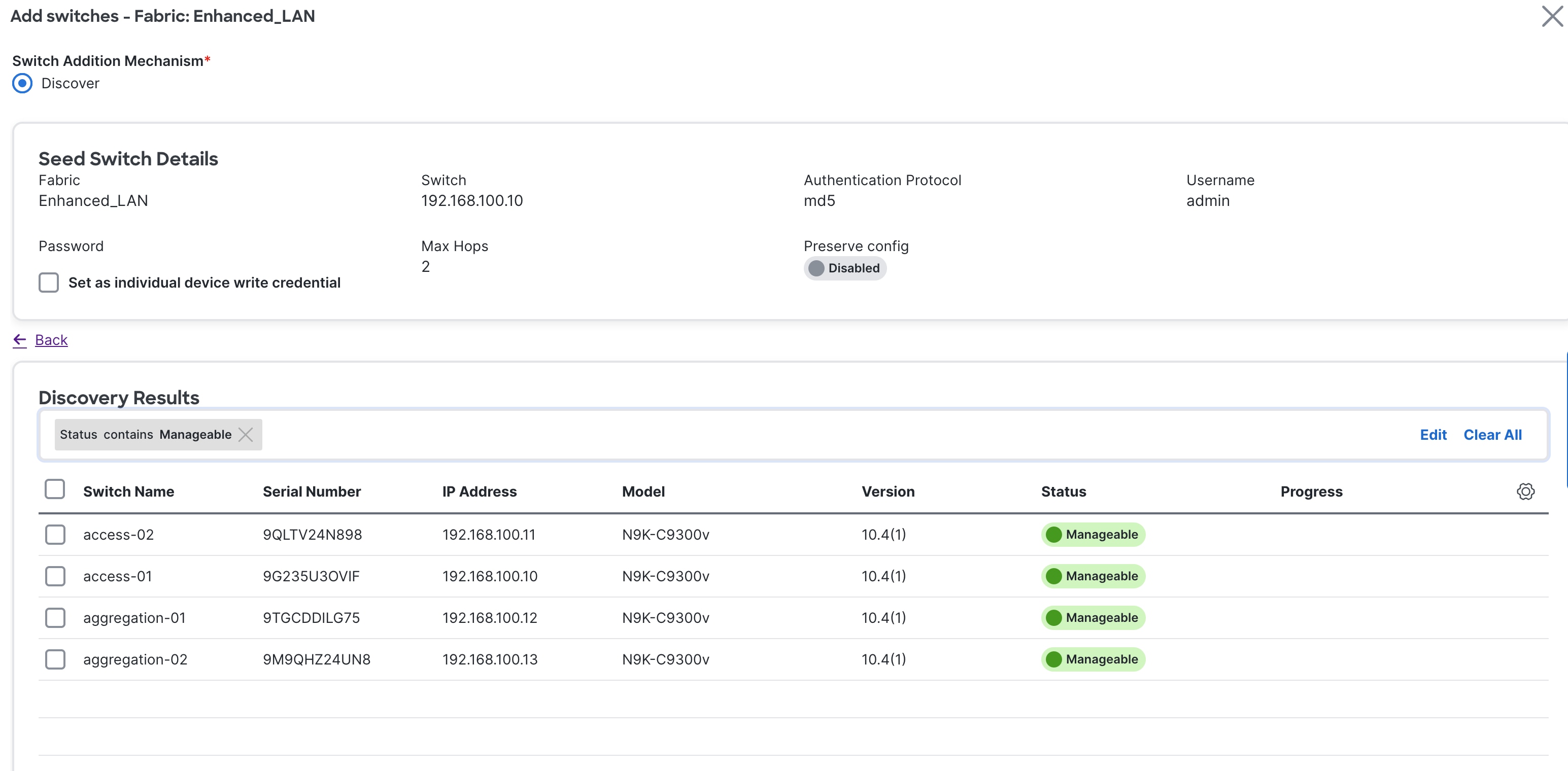
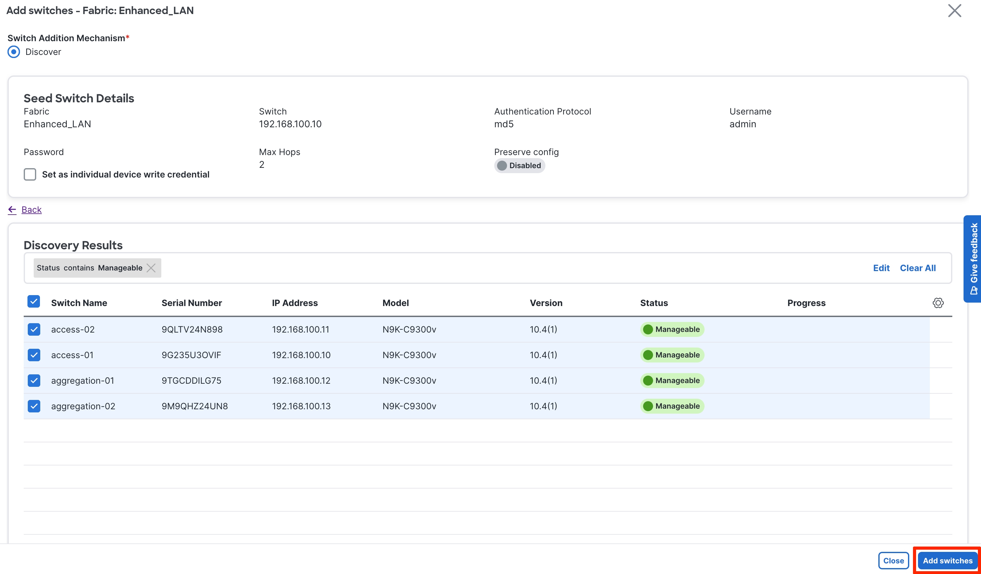
After ND discovers the switches, ND shows a list and the user can select the appropriate switches and add them to the fabric. Depending on whether this is a greenfield or brownfield import, ND performs specific actions as described above.
Step 3. Bootstrap (Power-on Auto-provisioning)
To bring up a new switch with the management IP address, default route, and start-up configurations, you can use power-on auto-provisioning (POAP) from ND. ND supports only Out-Of-Band POAP for switches in Enhanced Classic LAN fabric type and supports IPv4 and IPv6-related POAP options. ND can be the local DHCP server providing a management IP address and a default route for reachability when the switch is bootstrapped. You can also push the desired startup configurations and optionally an image with which to boot the switch. Alternatively, you can use an external DHCP server.
After you power up a switch, attach the cables, and add the switch to a POAP loop, the switch sends out DHCP requests on all the interfaces that are UP. Any DHCP server can respond to this request. The server providing the DHCP offer will be printed in the POAP logs in the switch. You must ensure that multiple DHCP servers are not deployed on the same segment, otherwise the POAP process may be impacted.
In this case, let us consider ND to be the local DHCP server that is reachable from the switch. The POAP script on the switch tries to download the startup configuration from ND, which is provided after the switch is bootstrapped from ND. The switch tries to download the configurations from ND, fails, and repeats the process until the switch is provisioned. In the meantime, ND hands out temporary management IP addresses and a default gateway to the switch (as defined in Fabric Settings). After the switch is bootstrapped, the management IP address that you provided for each switch replaces the temporary IP address.
In this example, we are trying to bootstrap two Access switches into an existing Enhanced Classic LAN fabric with Access and Aggregation switches that were discovered using their seed IP addresses. Alternatively, you can use a fresh fabric with no switches; both options are supported.
The first step is to enable bootstrapping in the Fabric Settings and optionally enable a local DHCP server (use ND as a DHCP server). You must also define the subnet scope and default gateway that ND will use temporarily while the switch is in its POAP loop after the switch has been powered up.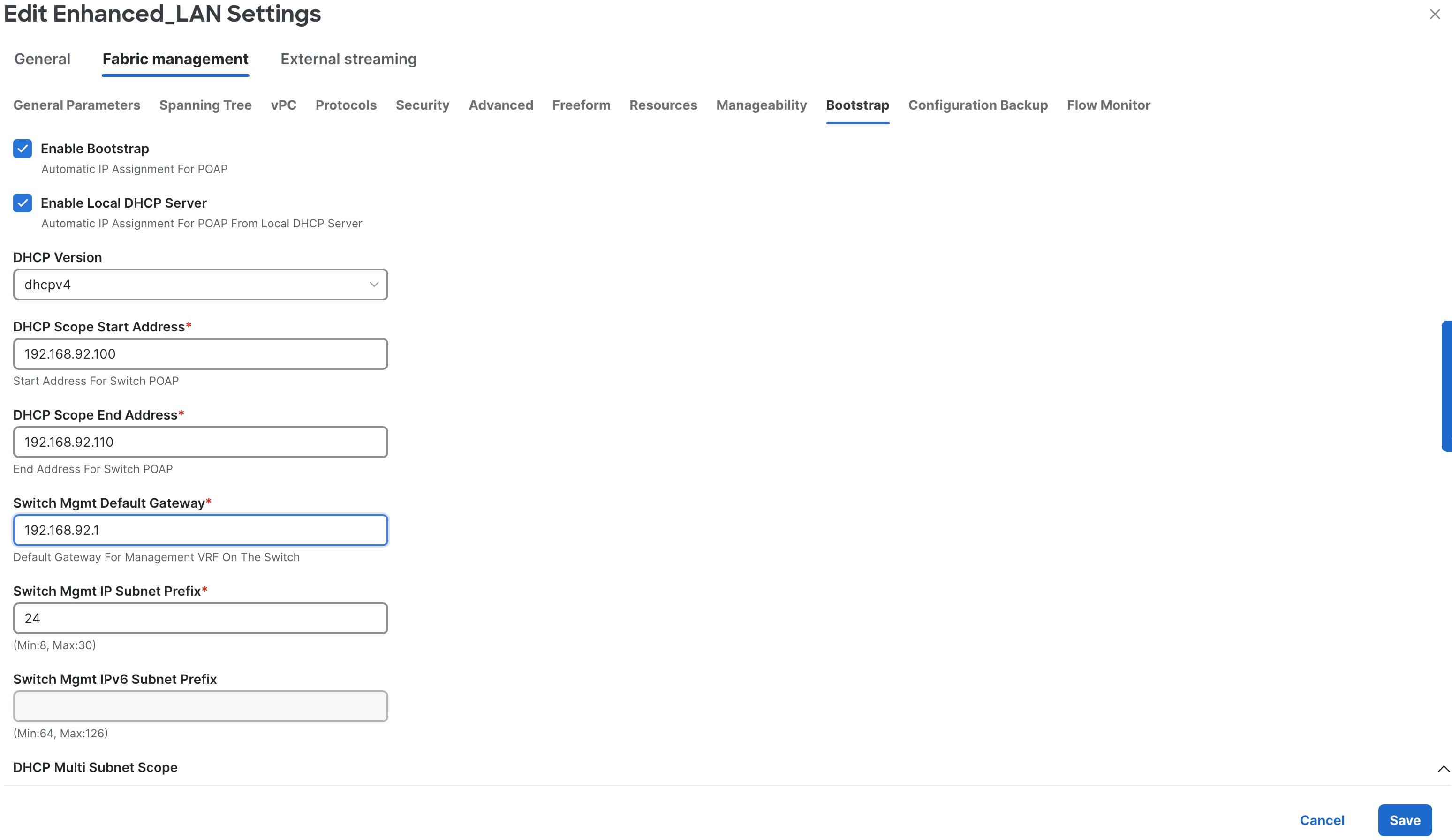
Under the specific fabric, Add Switches -> Bootstrap tab, the switches in the POAP loop are listed. At this point, ND hands out only temporary management IP addresses to the switches.
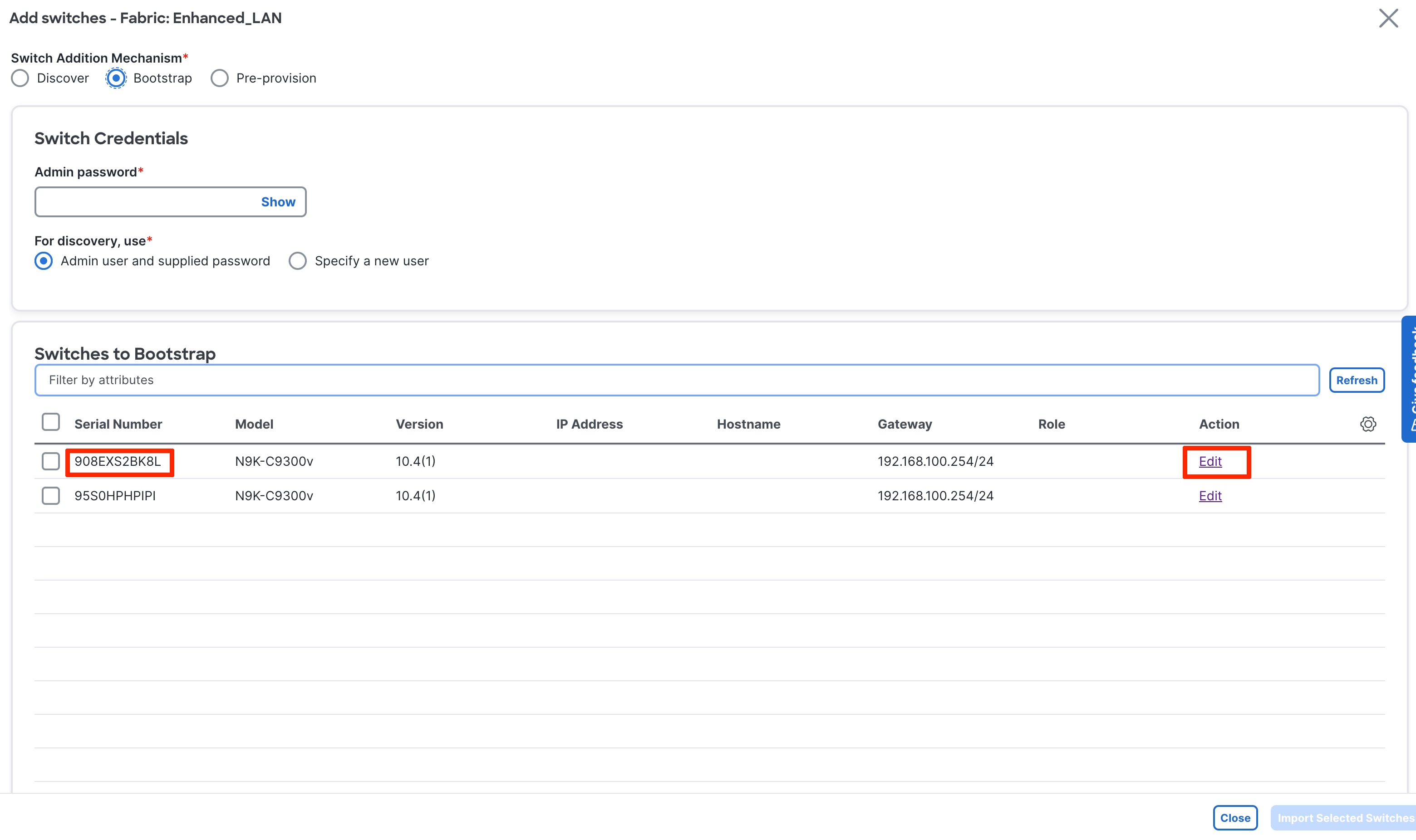
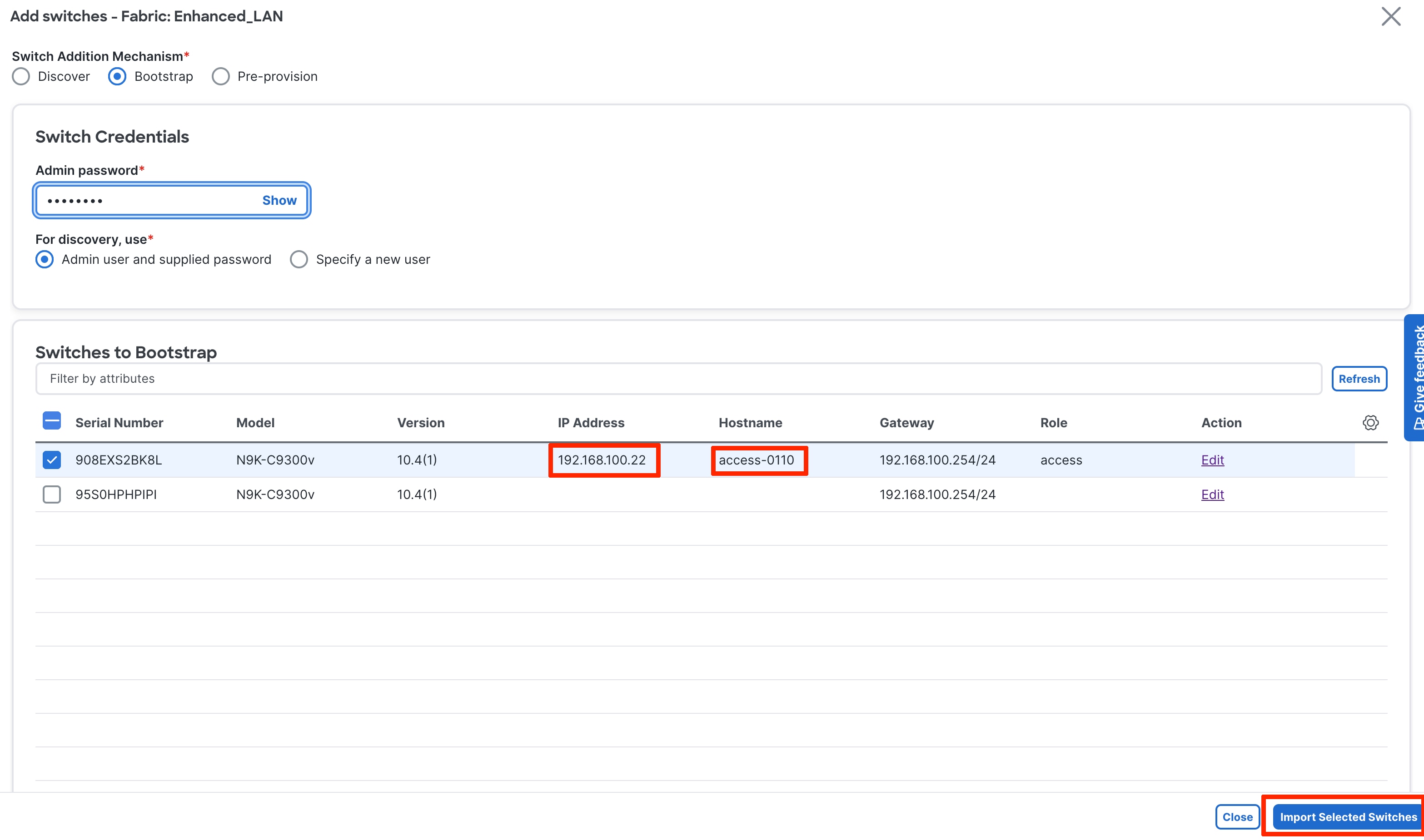
To bootstrap the switches and send the startup configuration down from ND to the switch, you must enter an Admin password.
Note: The primary use case for Specify a new user is AAA.
The AAA configurations must be part of the Manageability tab or Access/Aggregation freeform under Fabric Settings. In the Bootstrap tab thereafter, you must put a check in the Enable AAA Config box. That way, all configurations provided are used during bootup.
During the bootstrap process, the specified discovery user must be a valid AAA user. ND uses this user for switch discovery.
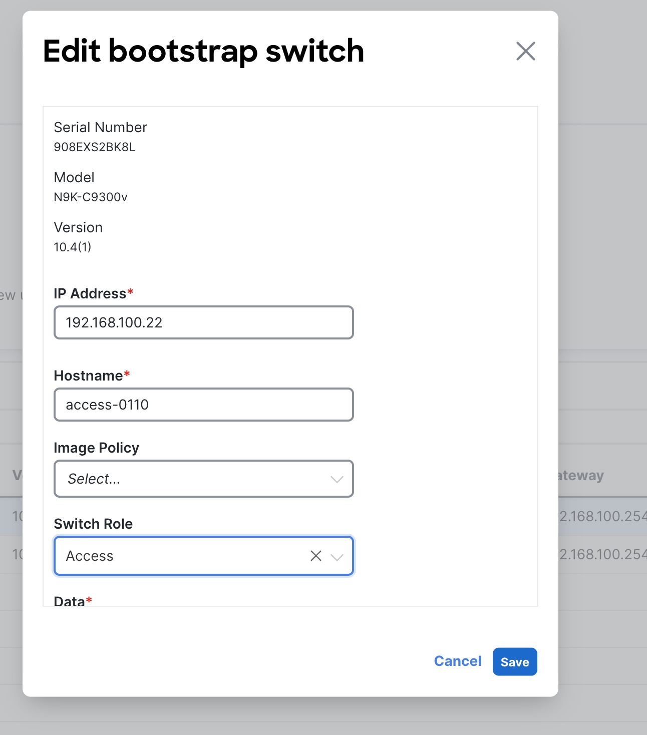
You must edit the properties in the Edit bootstrap switch dialog for each switch. That is, you must edit the mgmt0 IP address (this will be the permanent management IP address), hostname, switch role (in this case, Access or Aggregation), and, optionally, an image policy with which to boot the switch. The image policy as well as the image must be present in ND prior to choosing the image policy. For more information, see "Fabric Software (Fabric Upgrades)" in Nexus Dashboard, Release 4.1.x User Content.
The Data field is automatically populated.
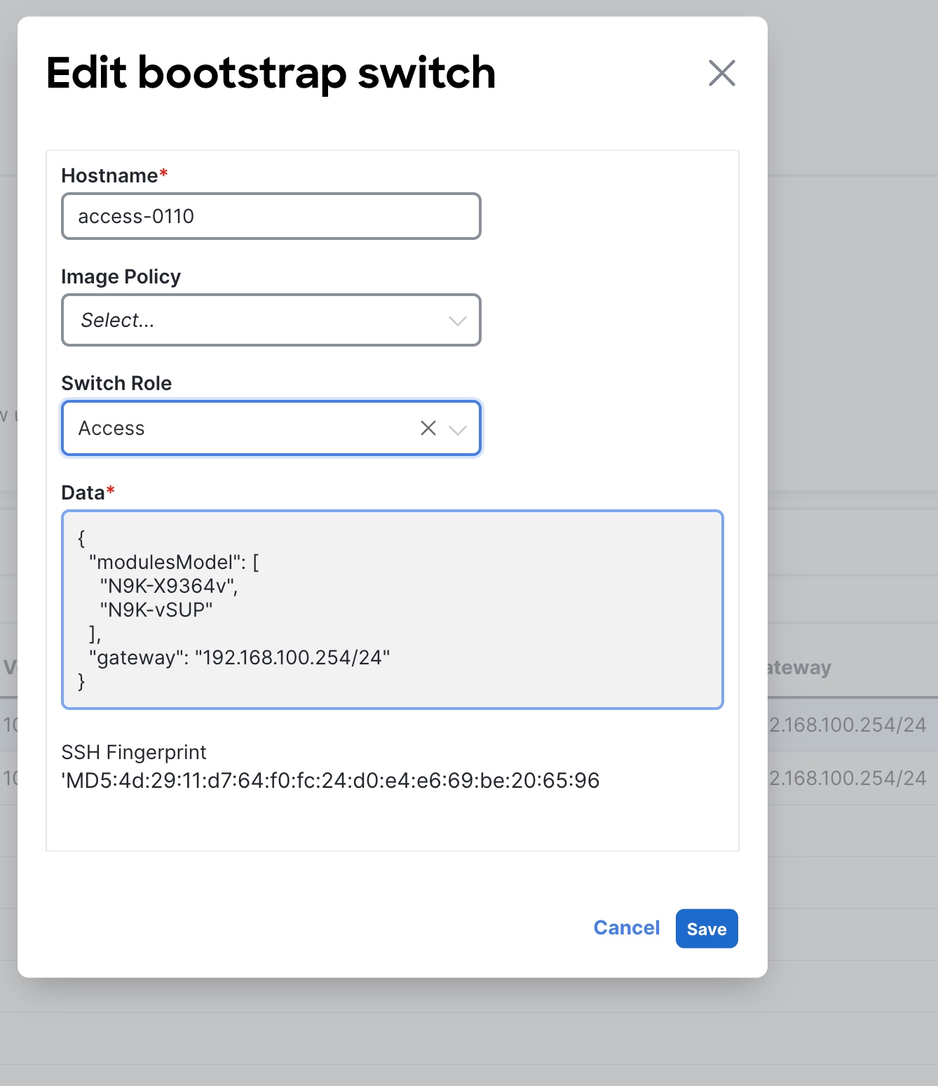
After you enter all the details and you click Import Selected Switches, the switches receive the respective startup configuration from ND and ND replaces the temporary mgmt0 IP address with the address that you entered in this step.
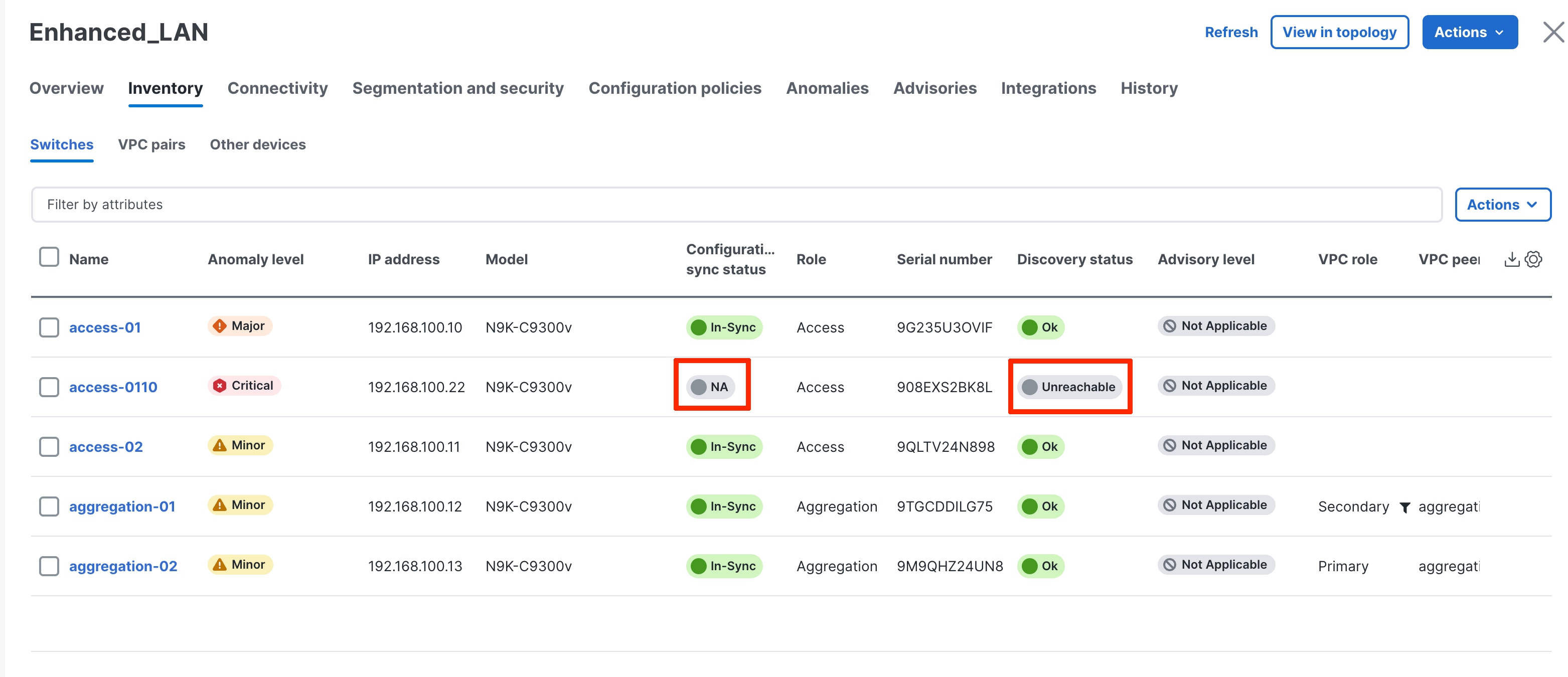
Now, you see the two switches bootstrapped under the Switches tab with Config Status as "NA," but the roles are defined.
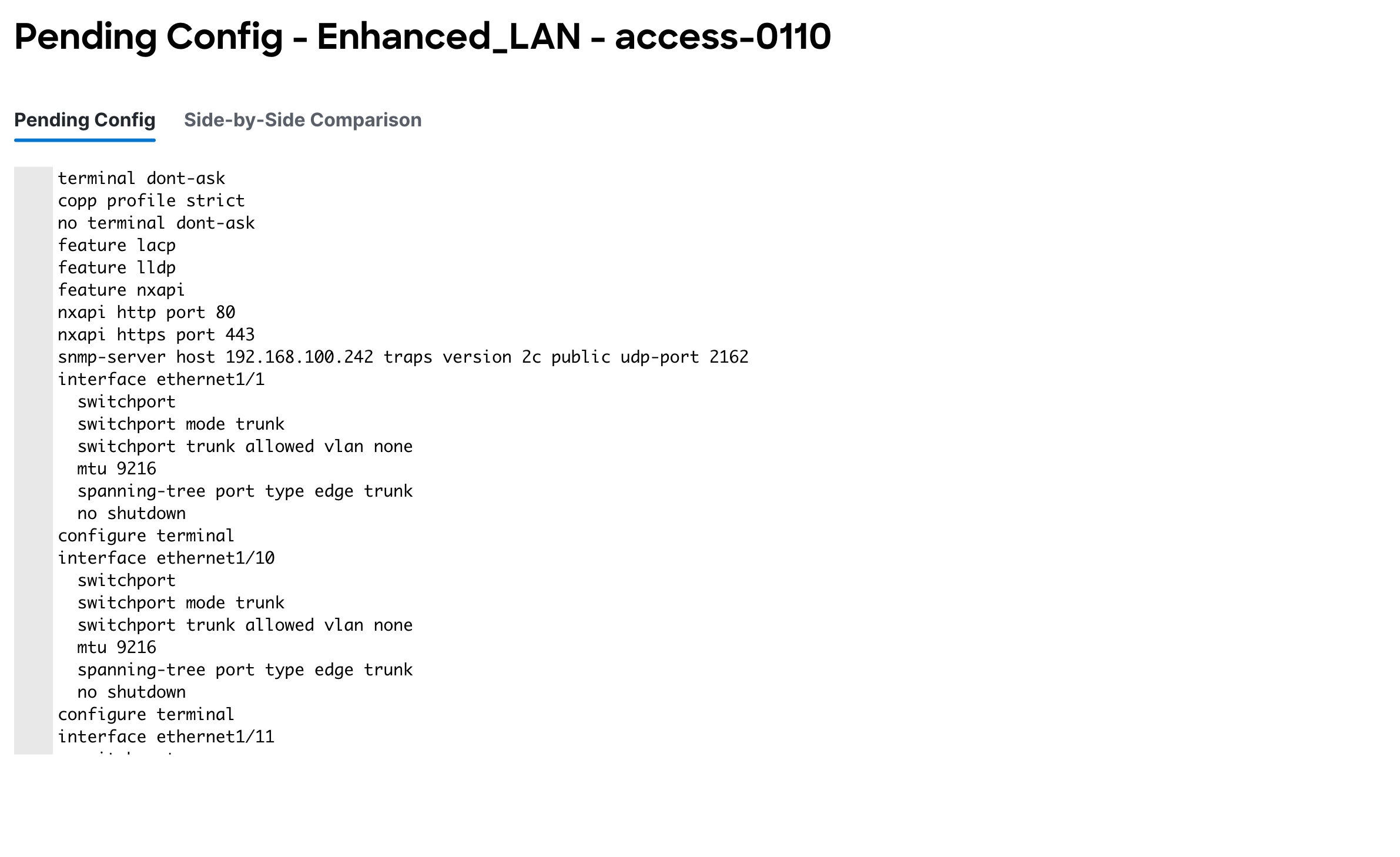
The startup configuration that ND pushed to the switches is as follows (for access-0110):
ipv6 switch-packets lla
power redundancy-mode ps-redundant
no password strength-check
hostname access-0110
username admin password xyz role network-admin
vrf context management
ip route 0.0.0.0/0 a.b.c.d
interface mgmt0
vrf member management
interface mgmt0
no shutdown
no cdp enable
ip address a.b.c.e/24
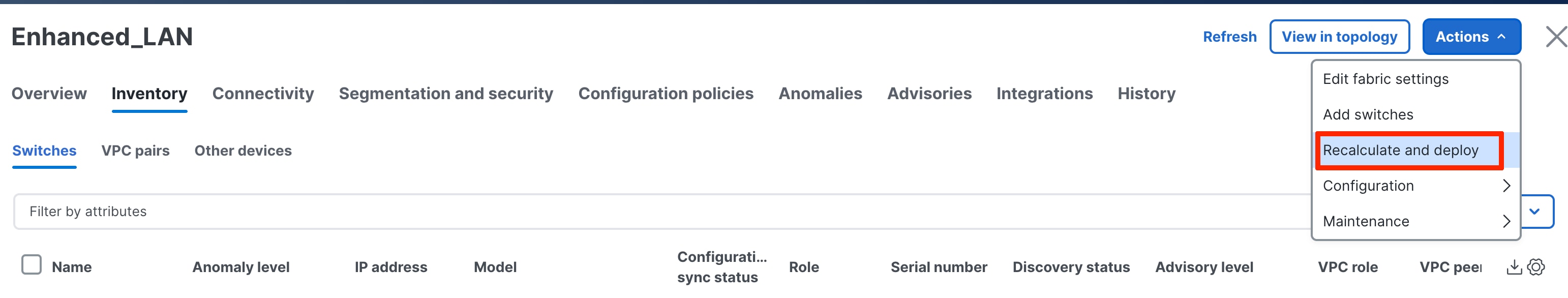
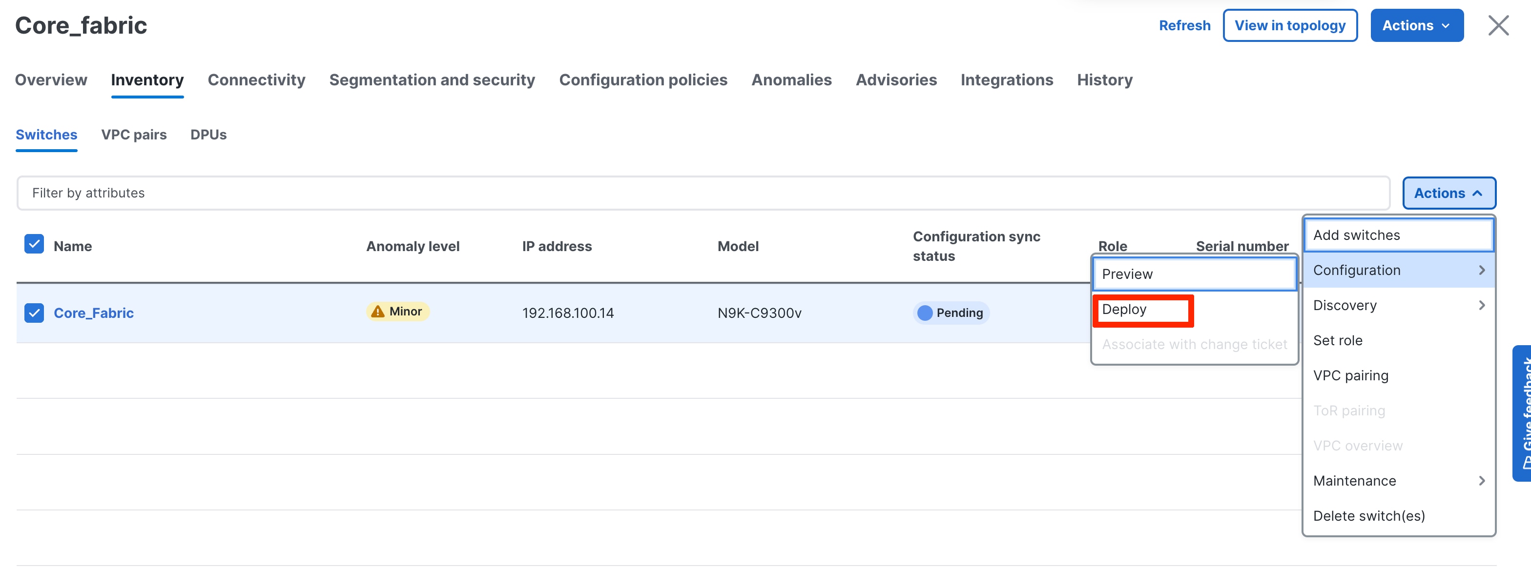
To inherit the fabric settings with respect to routing, spanning tree, FHRP, and so on, perform a "Recalculate and Deploy":
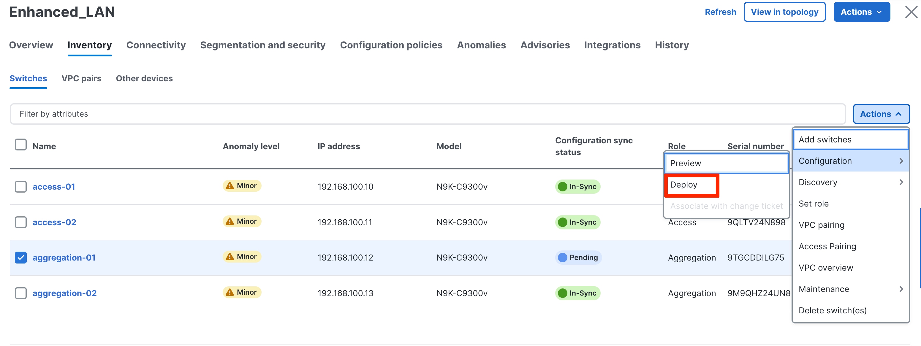
1. Select the switches.
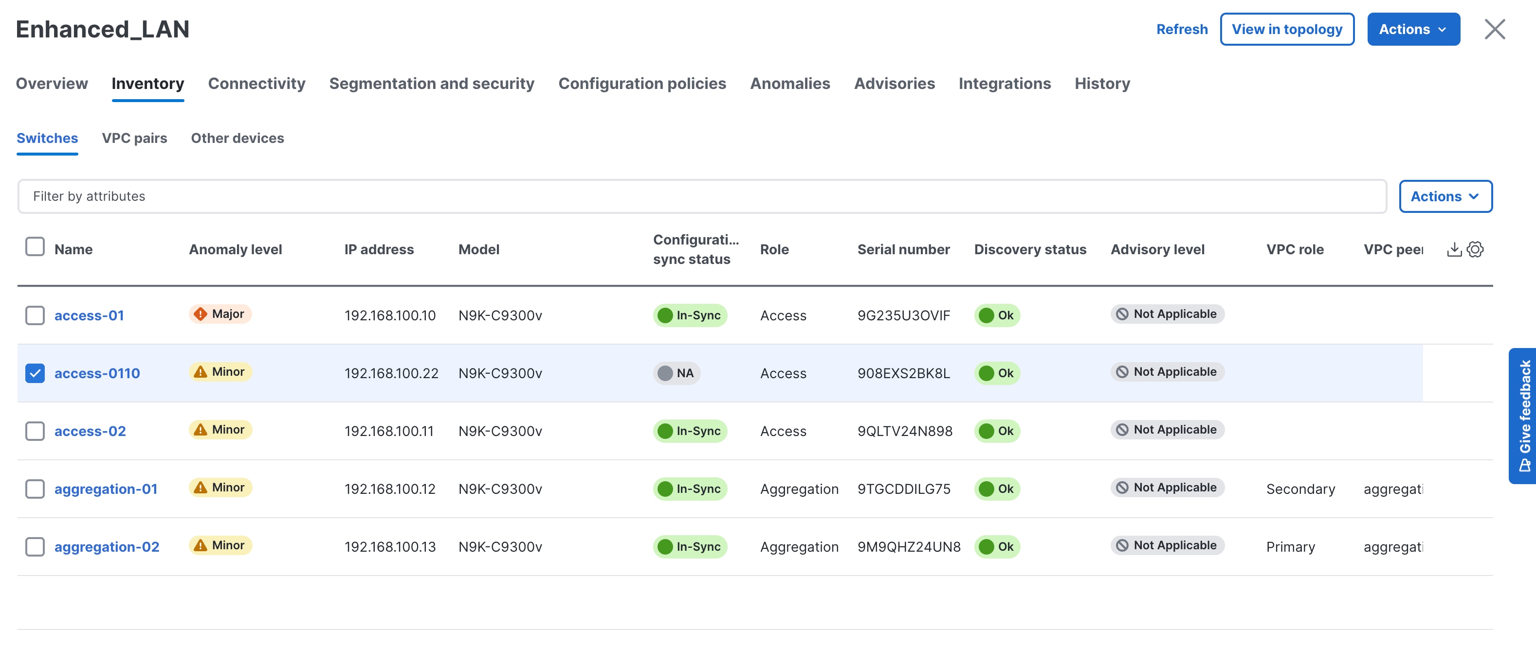
2. From the Fabric Overview page, choose Actions > Recalculate and Deploy.
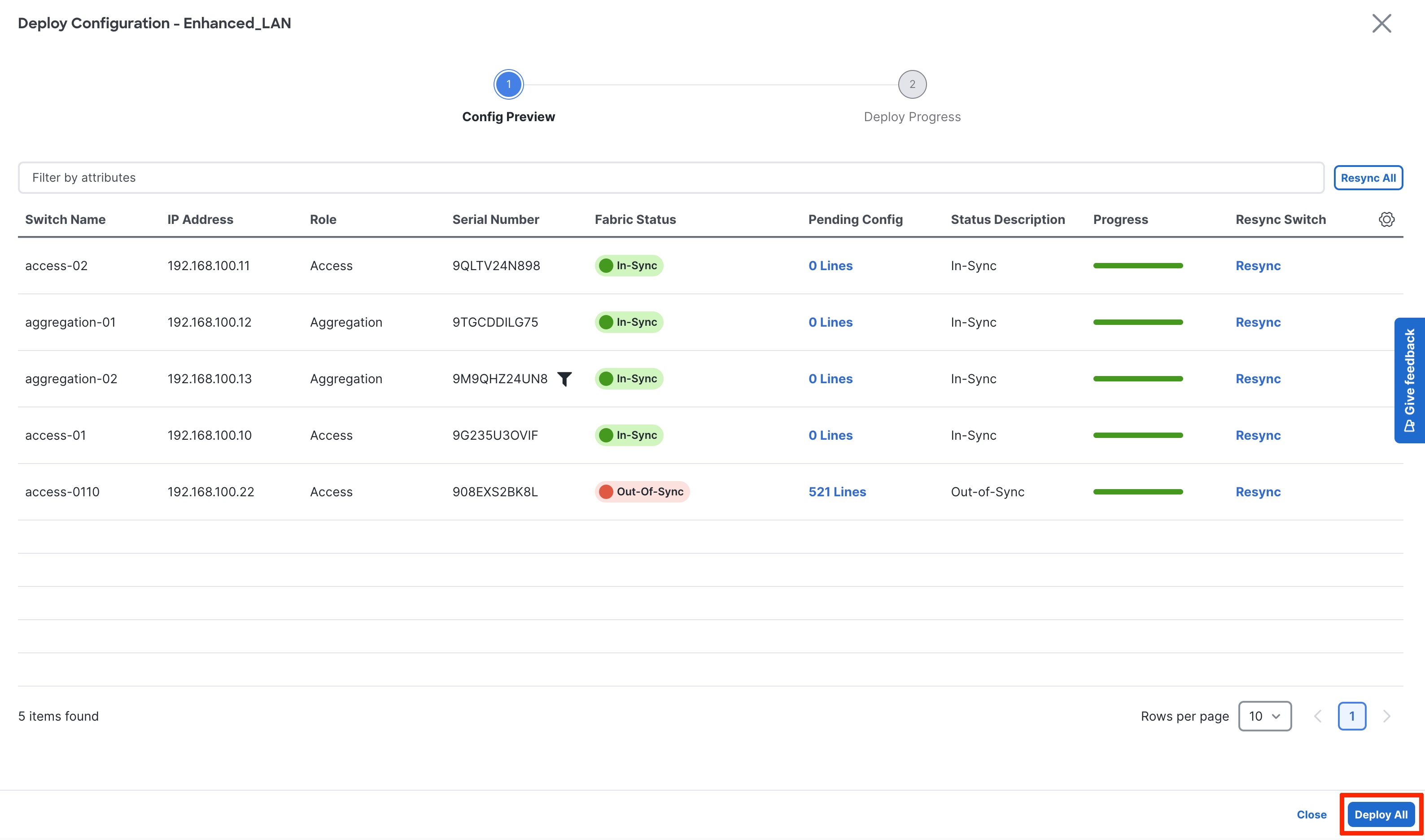
3. Review the configuration preview.
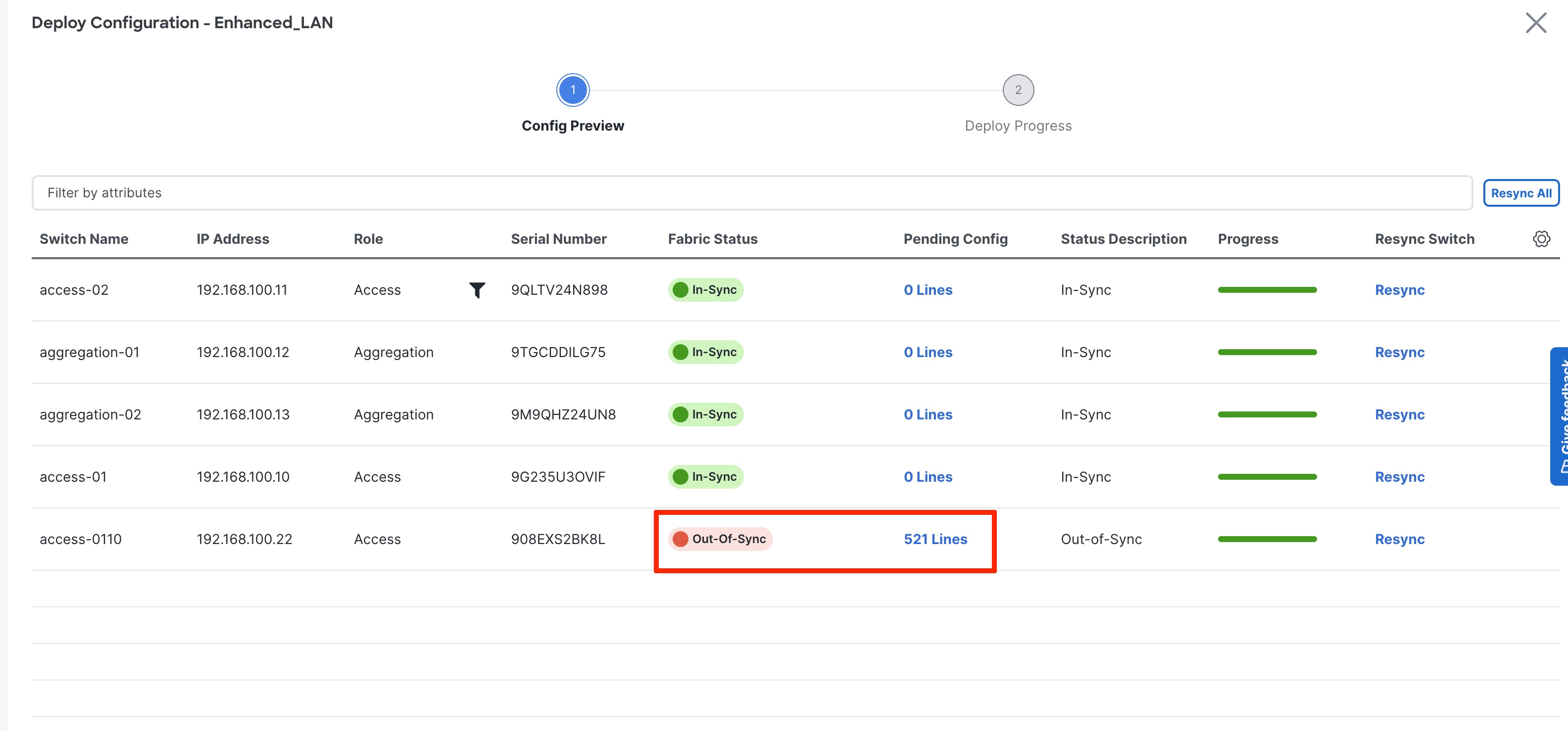
4. If everything looks accurate, click Deploy All to deploy the configuration for both switches.
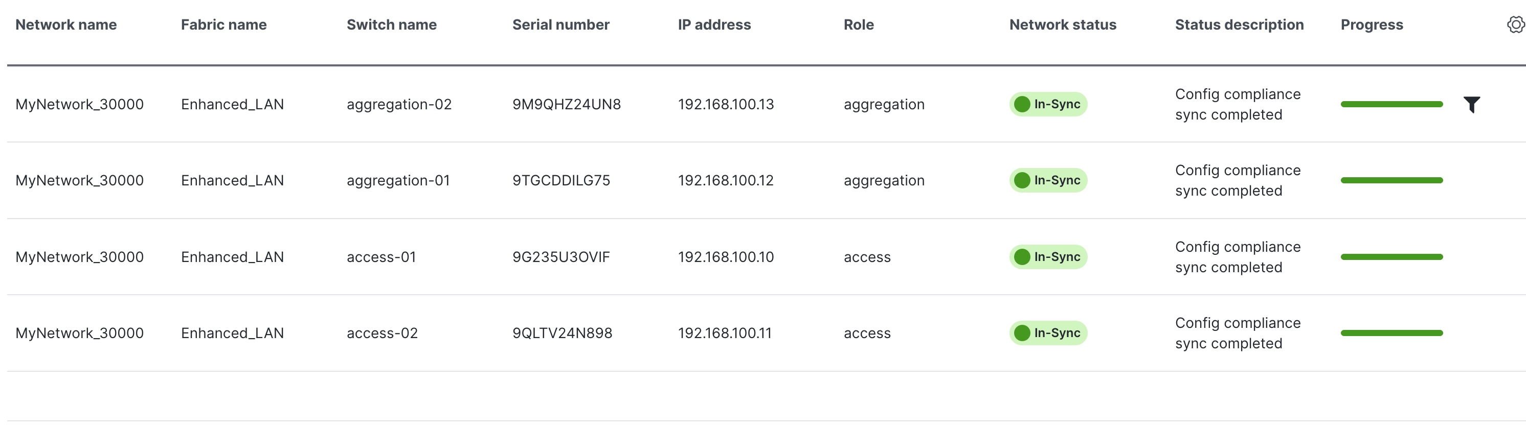
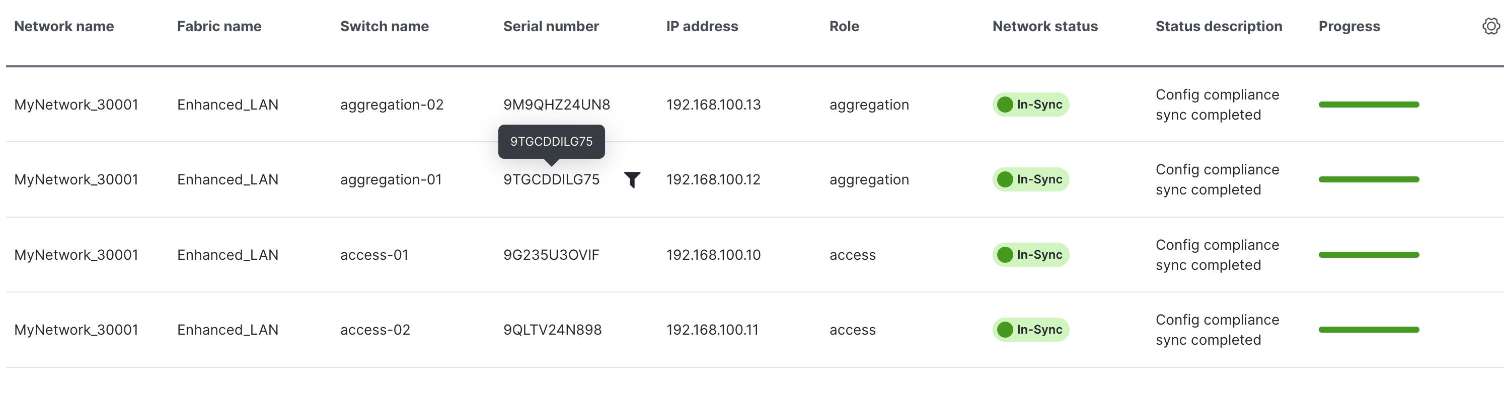
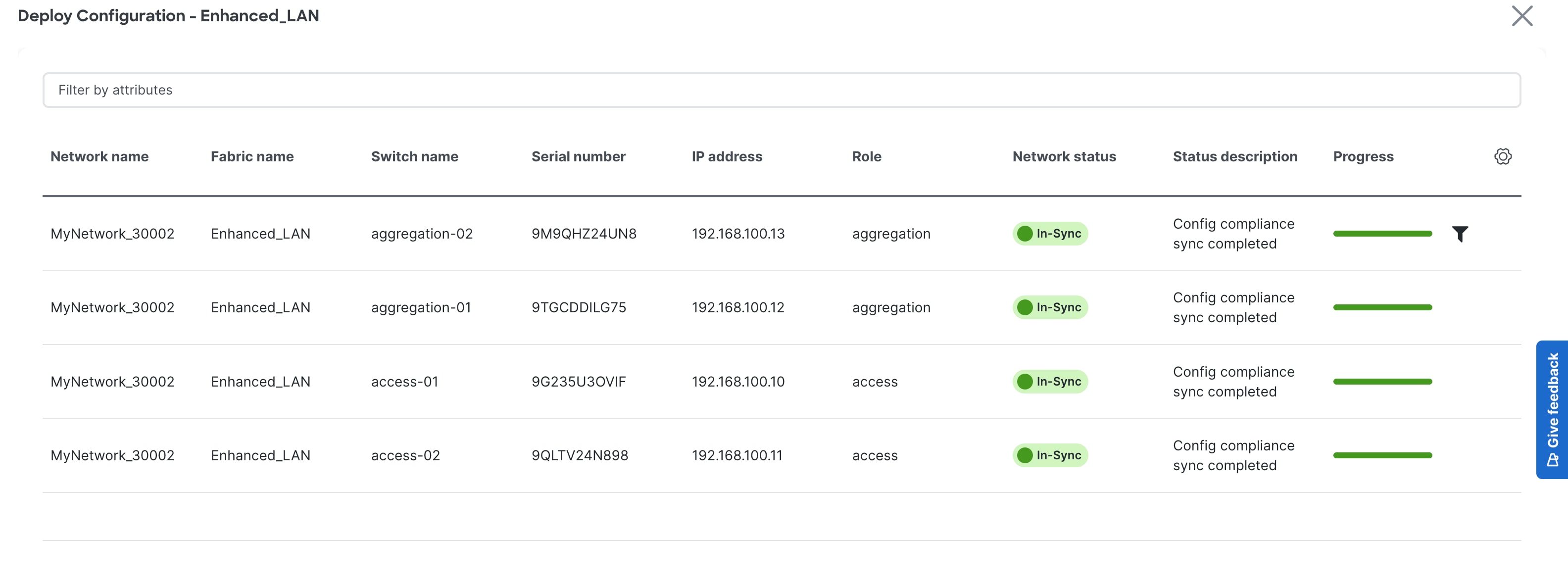
After deploying the configuration, all the switches are now "In-Sync":
This section discusses switches imported using seed IP addresses and not POAP.
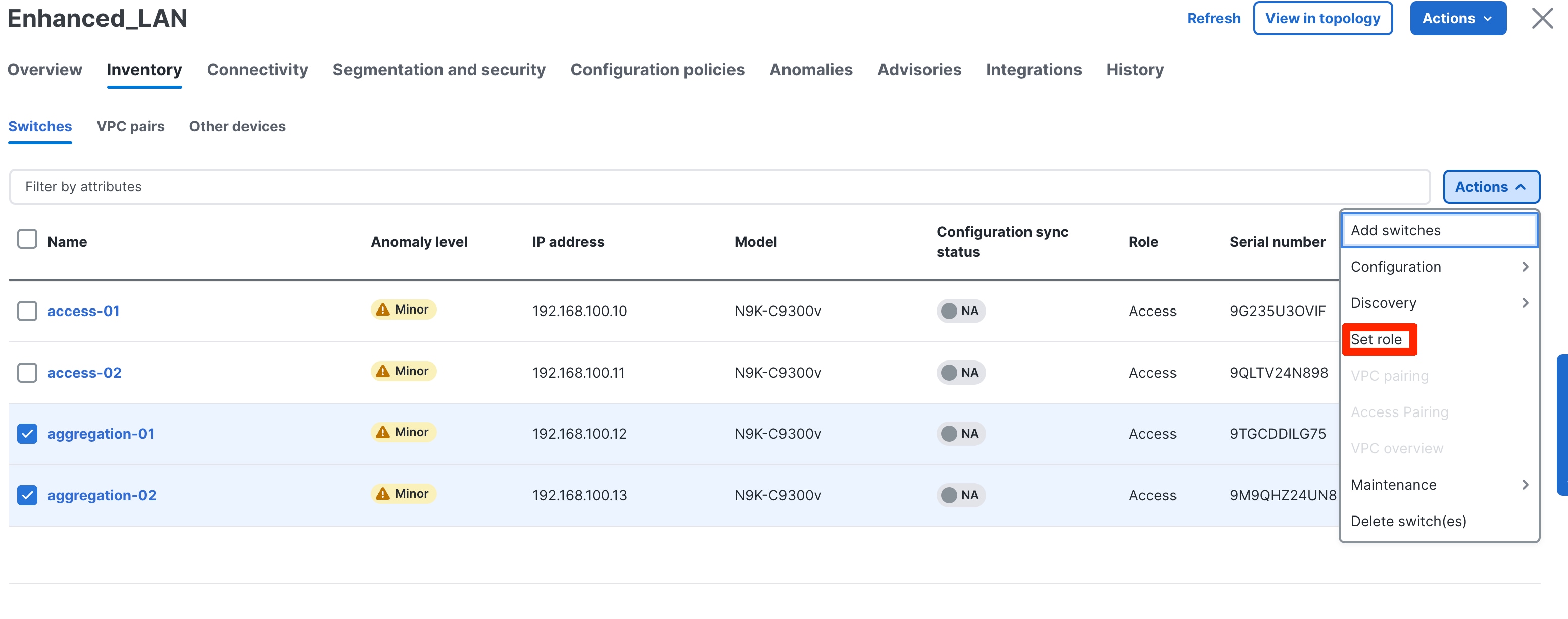
After you import the switches, you can begin defining your intent, as in what do we want this switch to be: Access or Aggregation? Based on this role, appropriate configuration is generated and pushed to the switches by ND.
Enhanced Classic LAN has two roles: Access and Aggregation. If the user has a Core layer, you must create a separate external and inter-fabric connectivity to place this Core switch, which is discussed in the next section.
Let us revisit the two topologies to define the roles appropriately:
1. 3-tier hierarchical network with a Layer 2/ Layer 3 boundary at the Aggregation and Core layers connecting to the WAN.
2. Collapsed Core where the Core and Aggregation layers are collocated on the same switch.
For #1, you can use the Access layer to connect to servers, the Aggregation layer as Layer 2/Layer 3 demarcation, and the Core layer in a separate shared fabric. The aggregation will also act as the spanning tree bridge and, optionally, a gateway with the relevant FHRP configurations.
For #2, because the Core and Aggregation layers are unified, you can use the Aggregation role as a collapsed Core layer. While serving as a Layer 2/Layer 3 demarcation, a bridge, and a gateway, this switch will also connect to the WAN (optionally using VRF-Lite, which is fully supported in the Aggregation layer). Day 1 aspects remain identical for a Collapsed Core topology, as discussed in the following sections. However, VRF-Lite will be between the Aggregation and WAN device instead of the Aggregation and Core layers. For more information, see the Day1 for Classic LAN section.
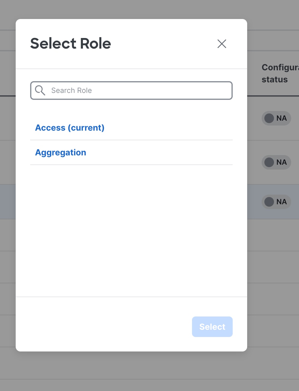
The following screenshots show how you can select the roles, with the default role being Access for non-modular Nexus 9000 switches. For Nexus 7000 switches, the default role is Aggregation. Also, for modular Nexus 9000 switches like 9500 the default role is Aggregation.
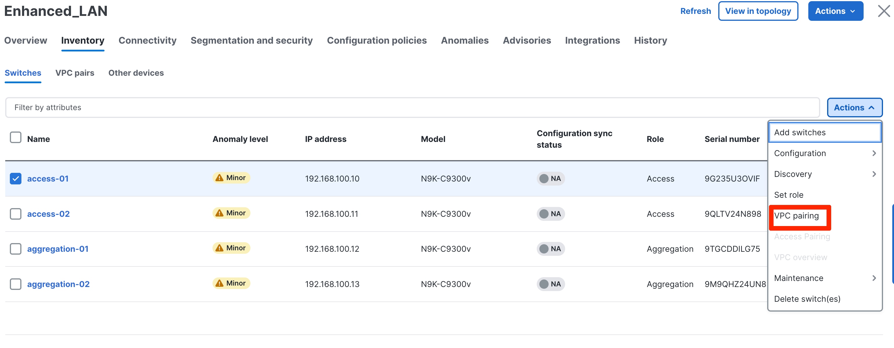
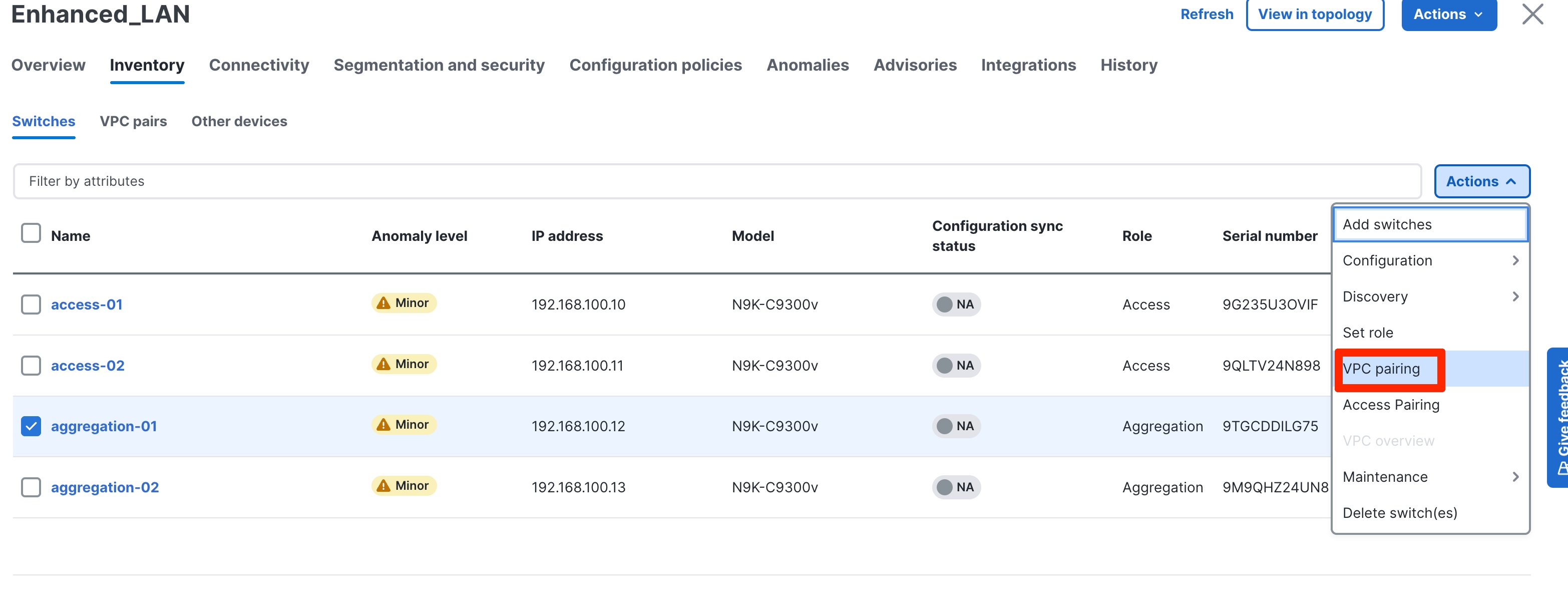
Step 5: Configure the vPC pairing
After you define the roles, you can pair the vPCs at the Access/Aggregation layer. vPCs at the Aggregation layer is mandatory in Enhanced Classic LAN, we recommend it as per Cisco best practices. A knob is placed in the Advanced tab of the fabric settings to automatically detect and pair Access-Aggregation for optimal traffic Engineering. By default, the auto Aggregation-Access pairing option is enabled. This means that on a Recalculate & Deploy (R&D), ND automatically detects the connectivity between the Access and Aggregation switches and generates appropriate configurations based on the detected supported topologies. The configurations include vPC domains that ND automatically pushes to both Access and Aggregation pairs. The links between these tiers are bundled into a common vPC logical construct.

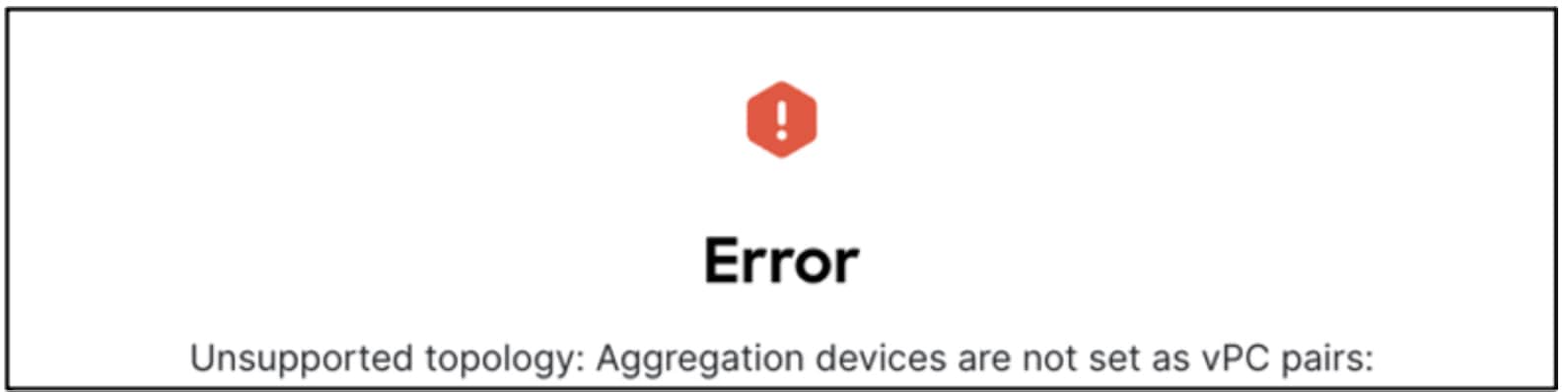
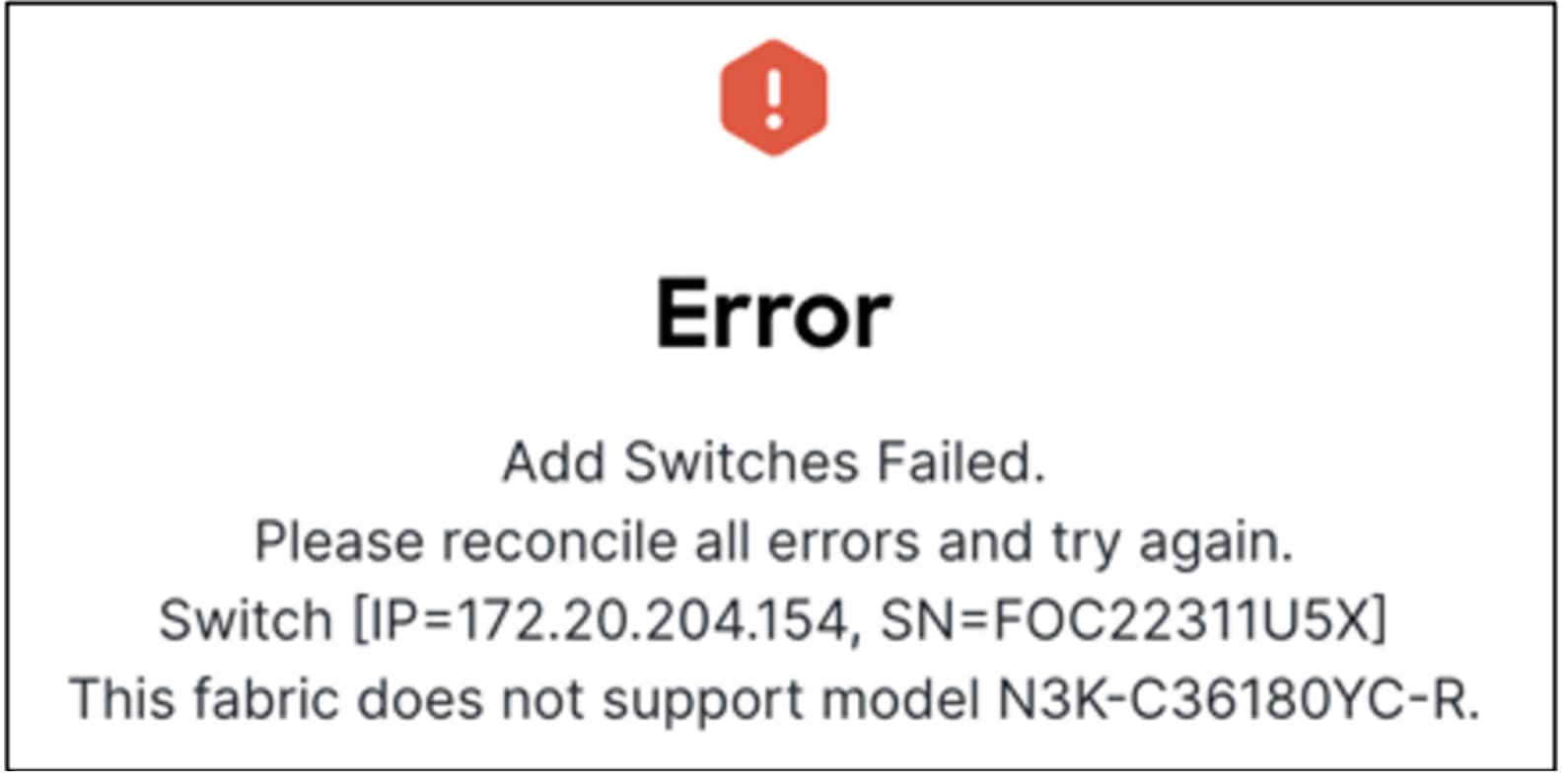
In cases where you have wired the Access/Aggregation layer such that it does not fit within the supported topologies or platforms, ND returns an appropriate error. The following screenshots show a few examples of the errors:
For vPC pairing at the Aggregation and the Access layer, the default option is to use the mgmt0 interface of the switches as the vPC Peer Keep Alive (PKA) link. However, if you configure a dedicated Layer 3 link for the vPC PKA, that will be honored by ND. You must configure this before you perform the Recalculate & Deploy step.
After you choose the Access switch for vPC pairing, ND shows the recommended devices. There is a back-to-back vPC between Access and Aggregation, which is auto detected, as shown in the following screenshot:
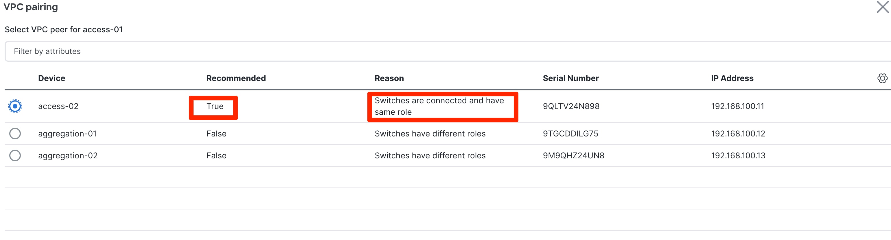
You do not explicitly need to vPC pair Access and Aggregation switches if you keep the Auto Pairing flag at its default value. Instead, ND automatically pairs the switches after this step.
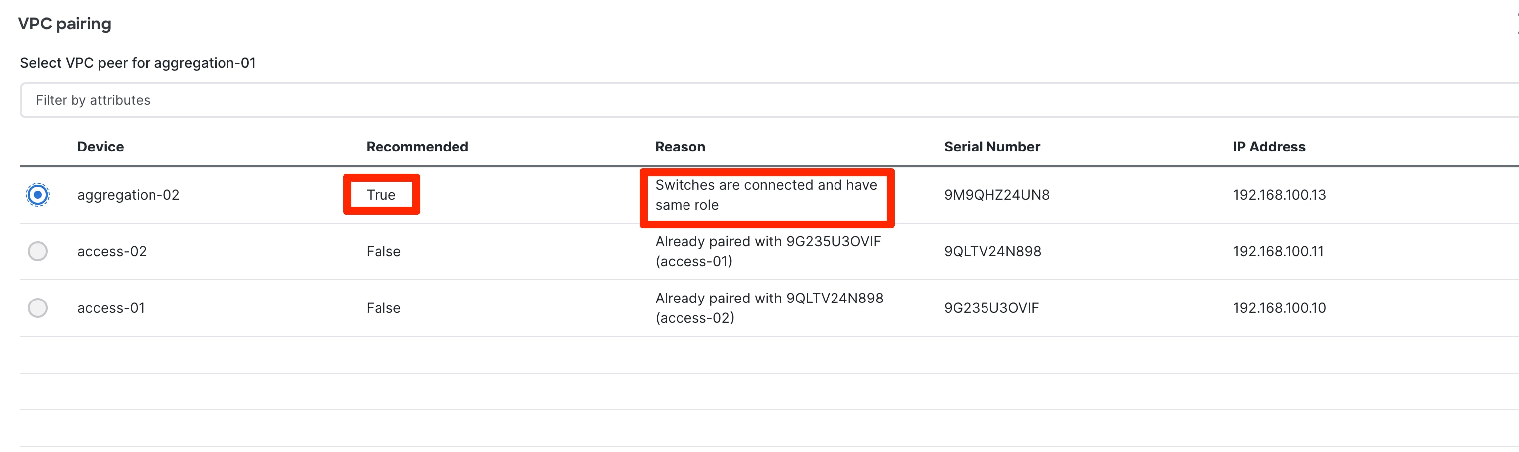
You must vPC pair Aggregation switches.
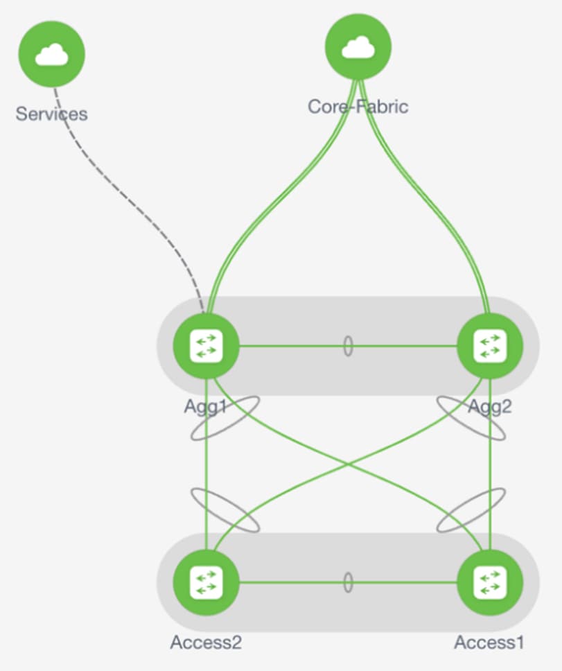
To visualize the pairing, you can navigate to the ND Topology page. As shown in the following screenshot, Access1 is paired with Access2, and Aggregation1 is paired with Aggregation2 based on user intent: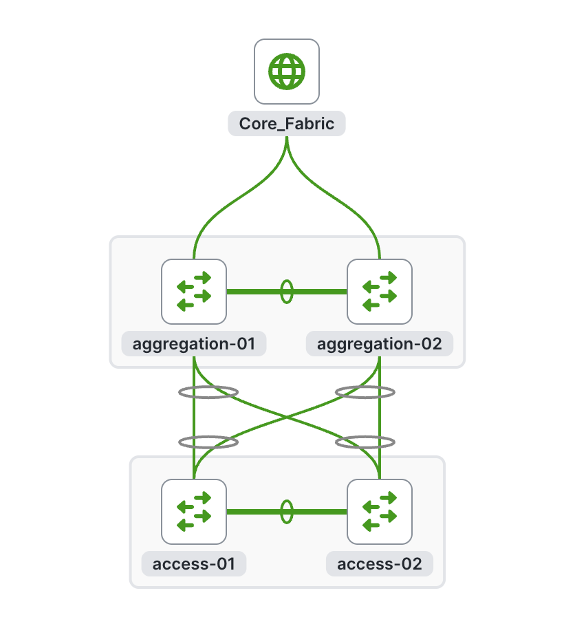
There is a back-to-back vPC present between Access and Aggregation, for which you do not need to take any explicit action to pair.
You will generate and push the vPC domain and back-to-back vPC configurations in the next step (On Recalculate & Deploy).
Step 6: Recalculate and Deploy
After you define the intent concerning the fabric, roles, and vPC, ND needs you to perform a "Recalculate and Deploy" (R&D). This means ND starts calculating the configurations required for each switch in the fabric. When doing so, it considers fabric as well as switch intent and shows you a preview of the configuration, which, after you approve, can be deployed.
In the case of a brownfield import, when you perform R&D, as part of the process ND performs various pre-checks on the switches comprising of the following things:
1. You must configure the Aggregation switches as a vPC pair, otherwise ND returns an error.
2. vPC consistency checks should indicate CONSISTENT on the vPC pairs. vPC pairs are mandatory at the Aggregation layer, but optional at the Access layer. If configured on the access layer, the vPC pair should be consistent.
3. ND performs various topology checks to ensure that the current deployment being imported into the ECL fabric has the right connectivity in terms of fitting it into the supported topologies. If ND discovers any other topology, ND displays an appropriate error.
4. Appropriate FHRP protocol configured in fabric settings must match what is configured on the Aggregation switches.
Note: On a successful brownfield import, ND learns the existing state and configurations (ND can now incrementally manage these things).
All vPC pairing-related information including the vPC domain, the vPC peer keepalive (KPA), and the vPC peer link are learned for the Aggregation and Access layer switches (if applicable). All interface-related configurations are learned, including access, trunk, routed, sub interface, port channels, and vPCs. The port channels or vPCs connected between the Aggregation and Access layers will be appropriately mapped to the "uplink_access" policy, along with the mapping of which Access switches map to which Aggregation switches. In addition to the network/VRF attachments, VRF-Lite related configurations are also learned. The ND Resource Manager will have appropriate accounting of various resources used on the switches, including but not limited to: VLANs, port channel IDs, vPC IDs, and loopback IDs.
The following procedure performs R&D:
1. Choose Recalculate and Deploy.
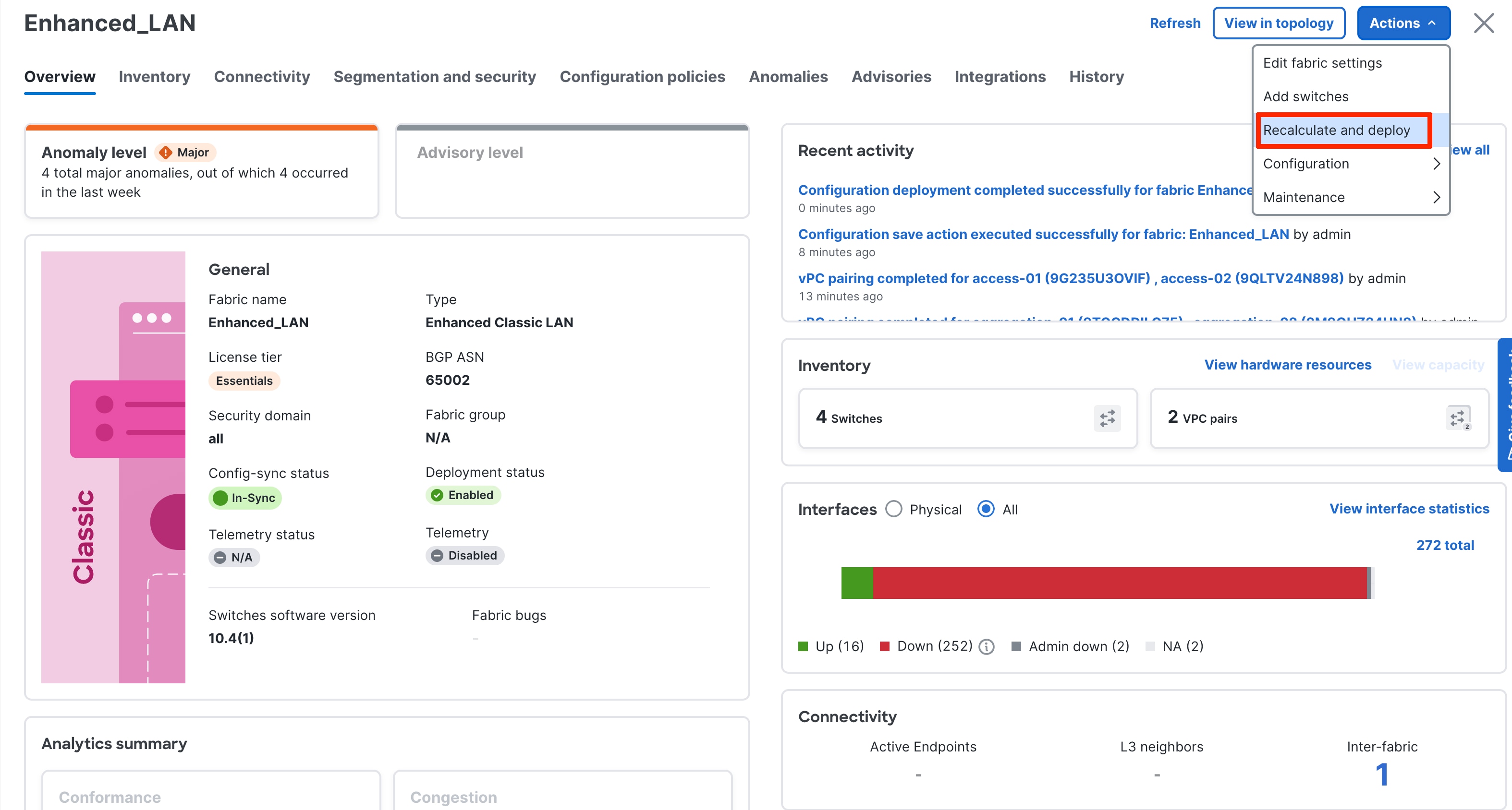
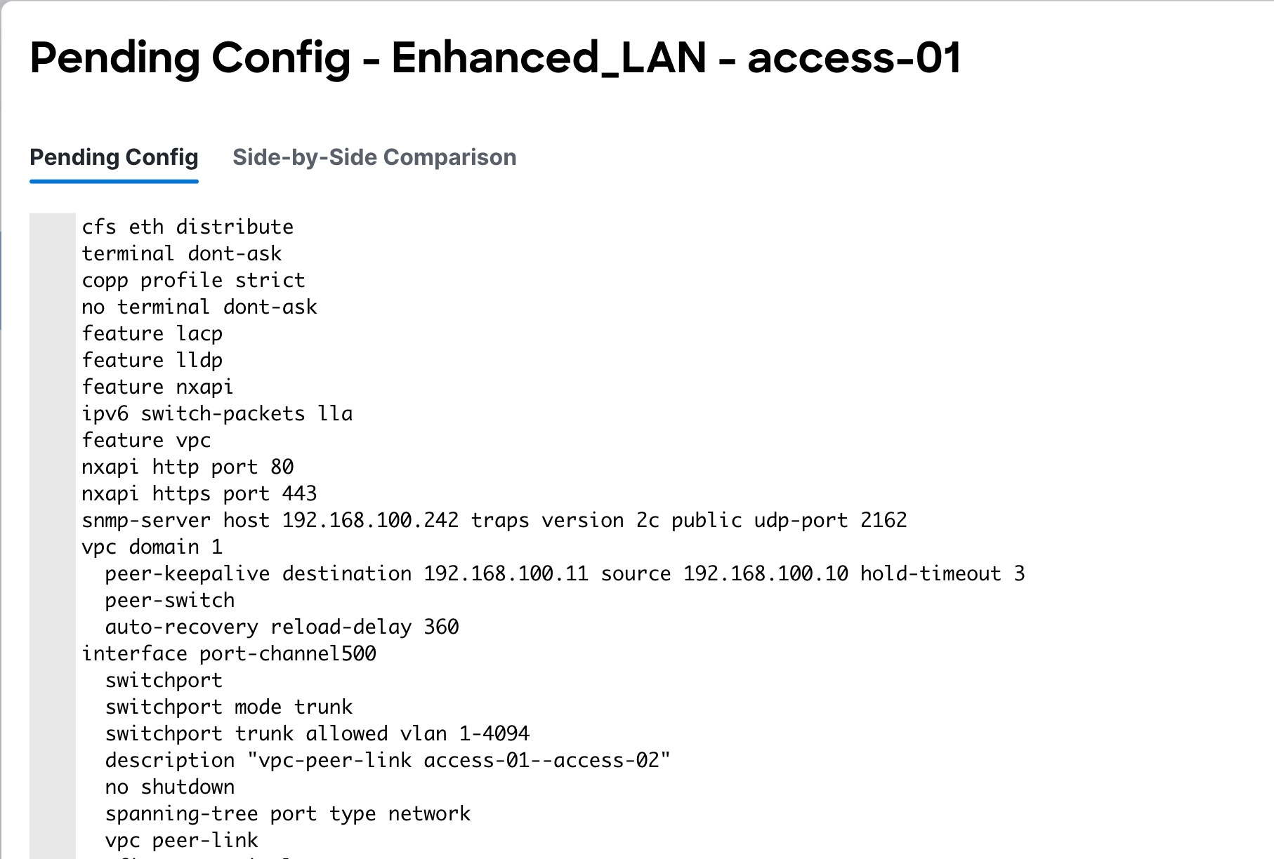
2. Preview the configuration. The configuration to be provisioned will be more substantial for a greenfield import compared to a brownfield import.
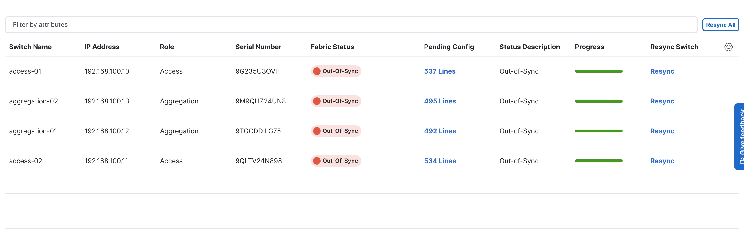
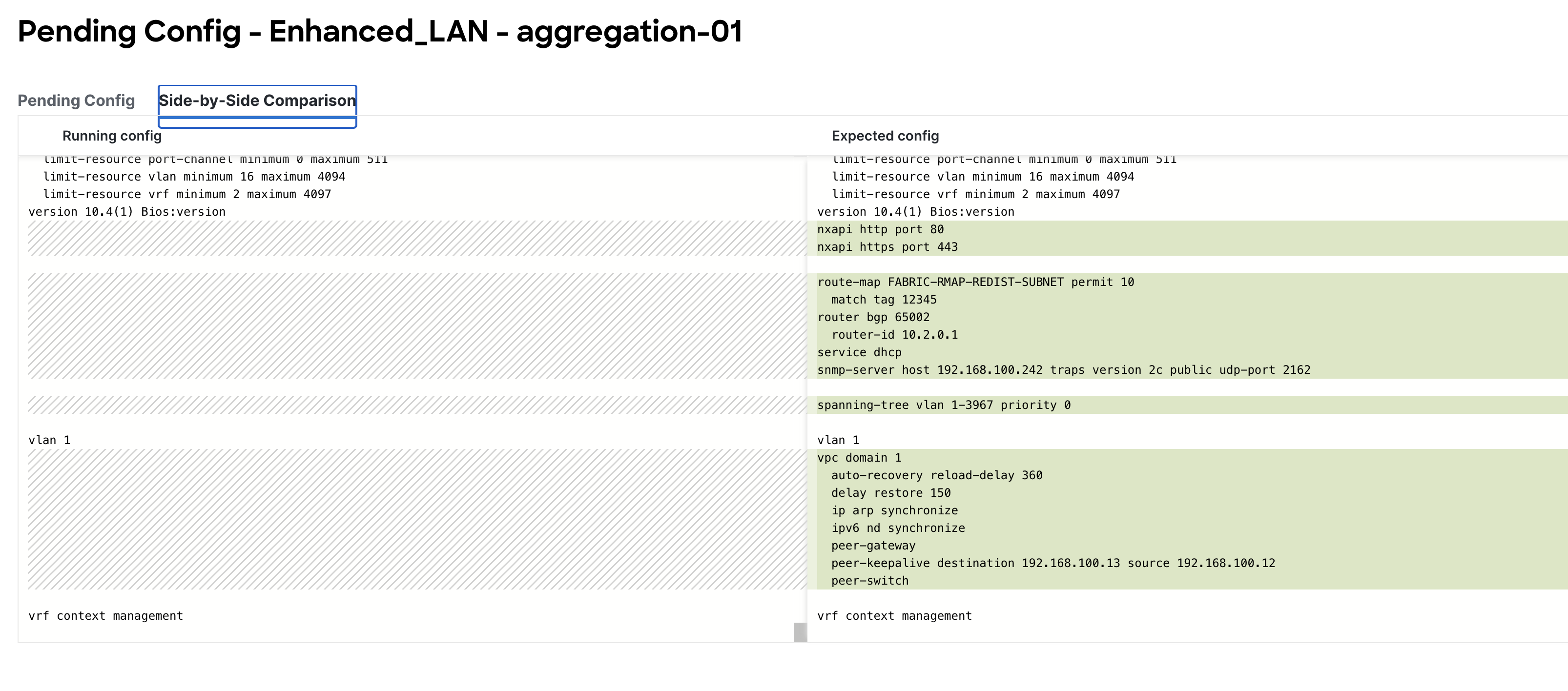
Example of Access Configuration:
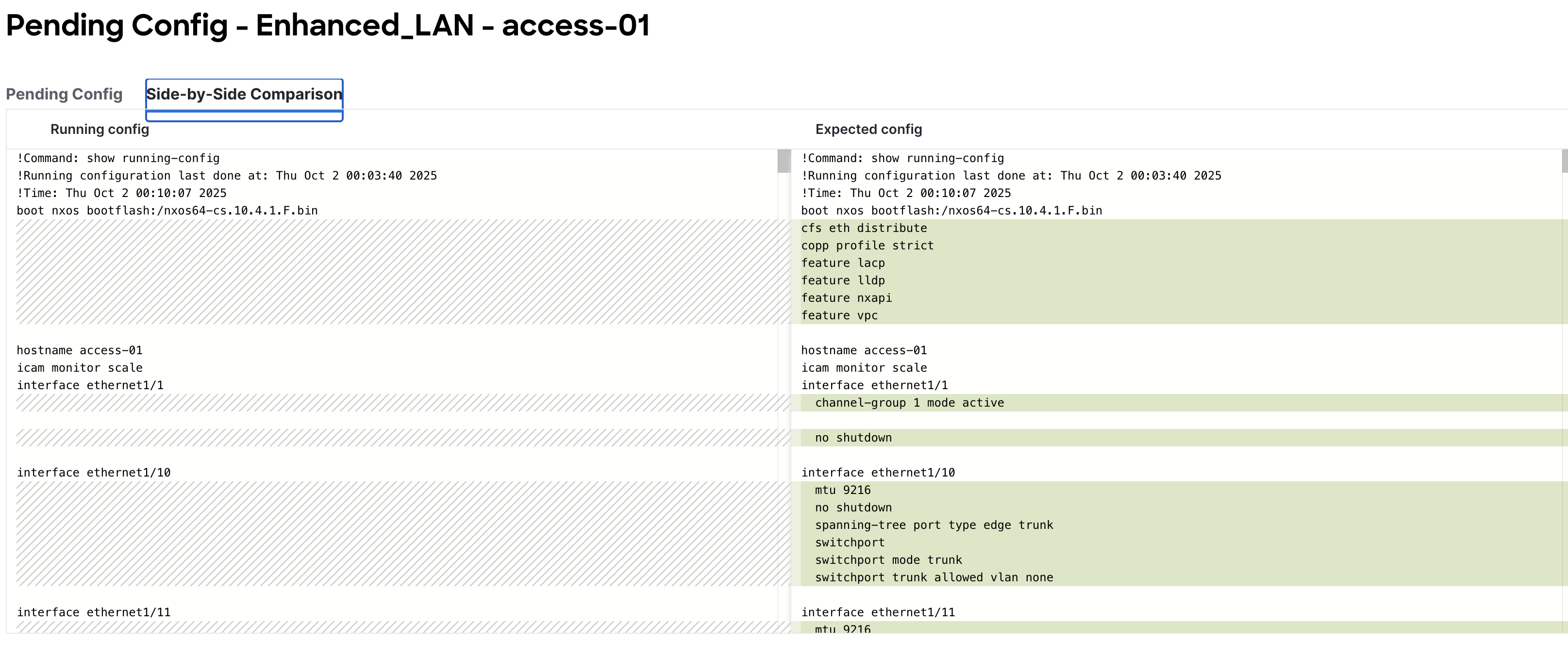
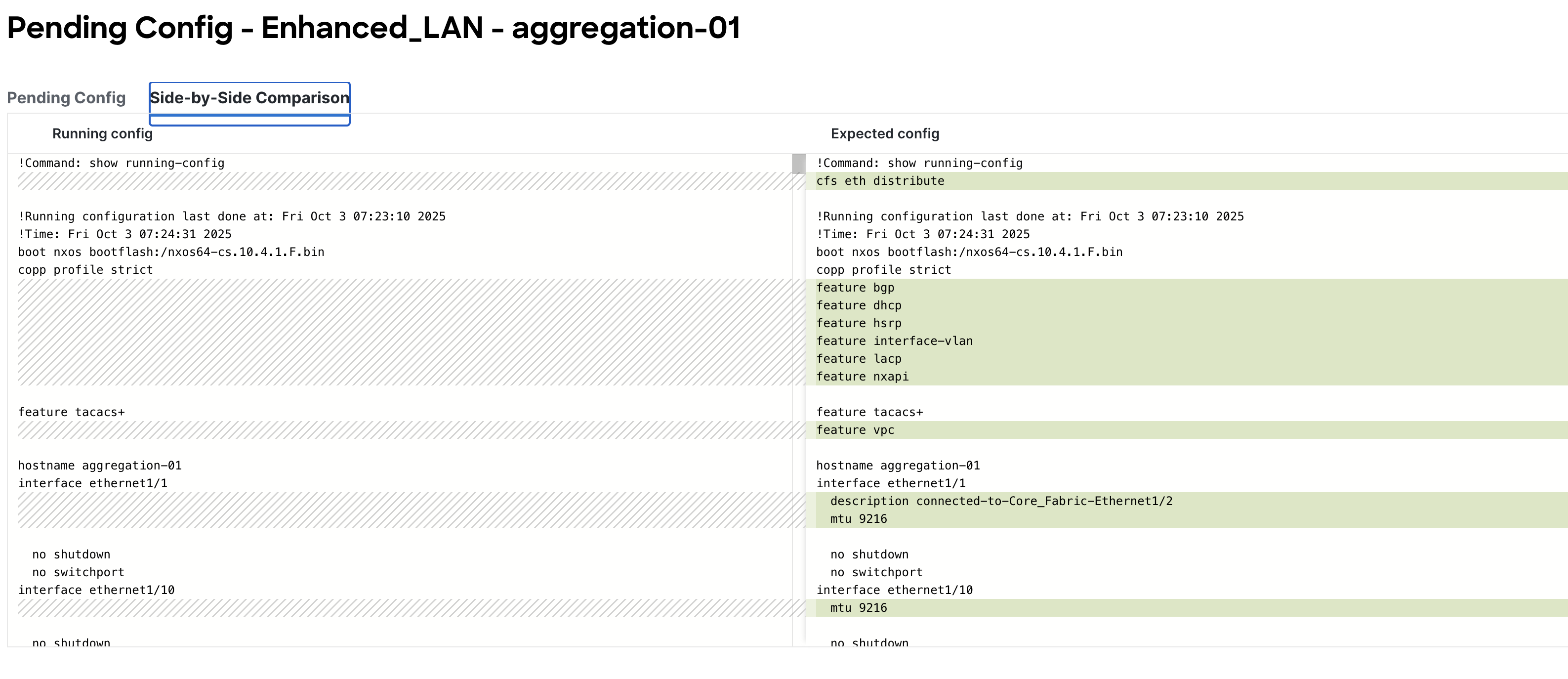
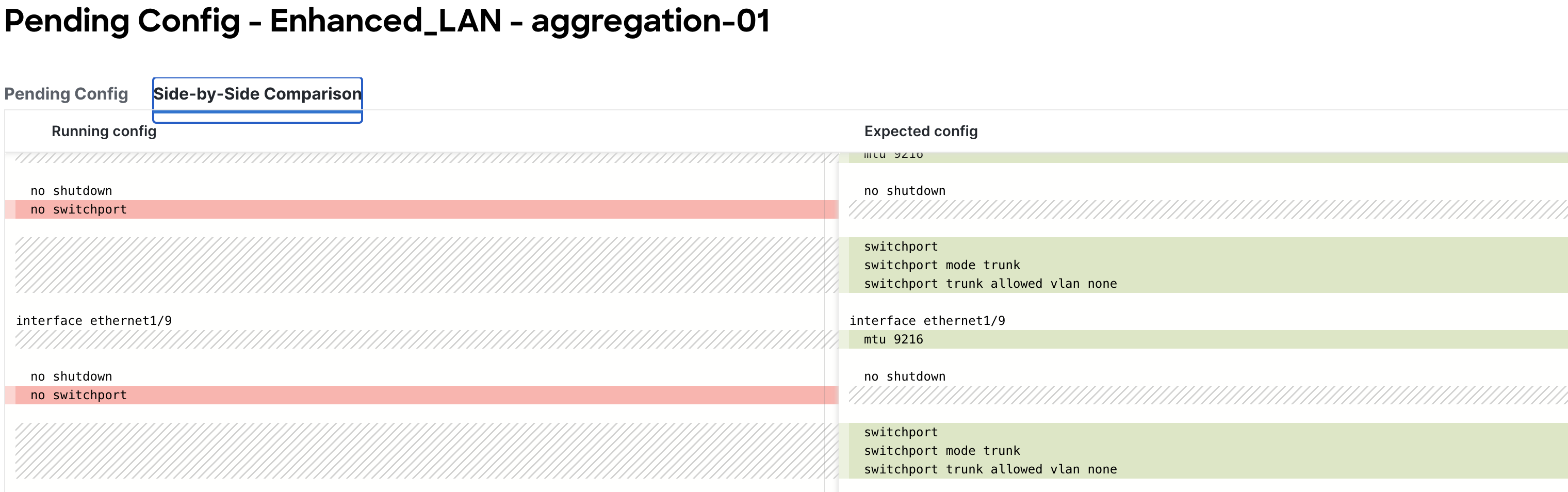
Side By Side Comparison View
Example of Aggregation Configuration: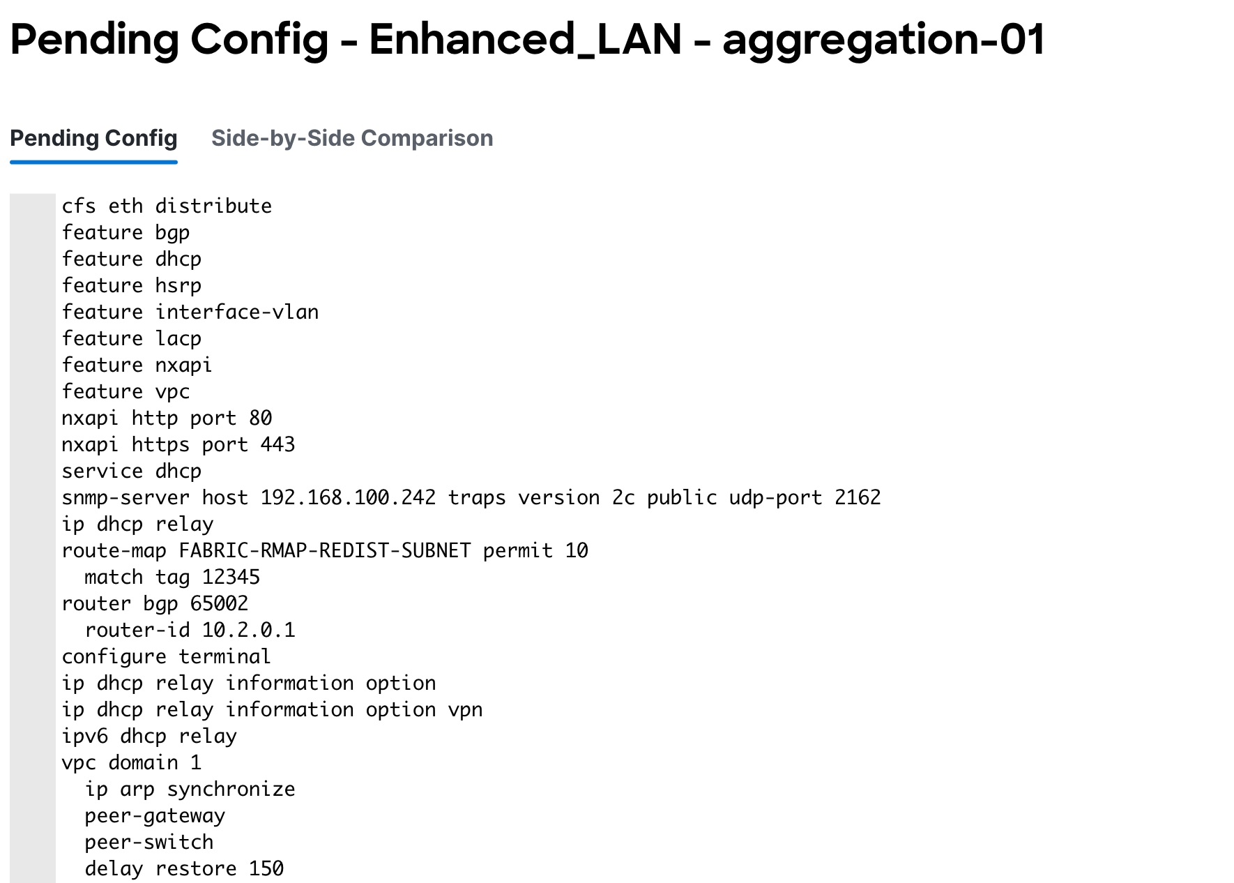
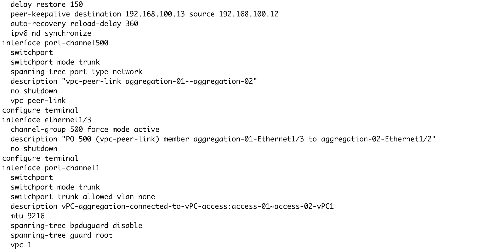
3. Deploy and make sure the Config Status is "In-Sync".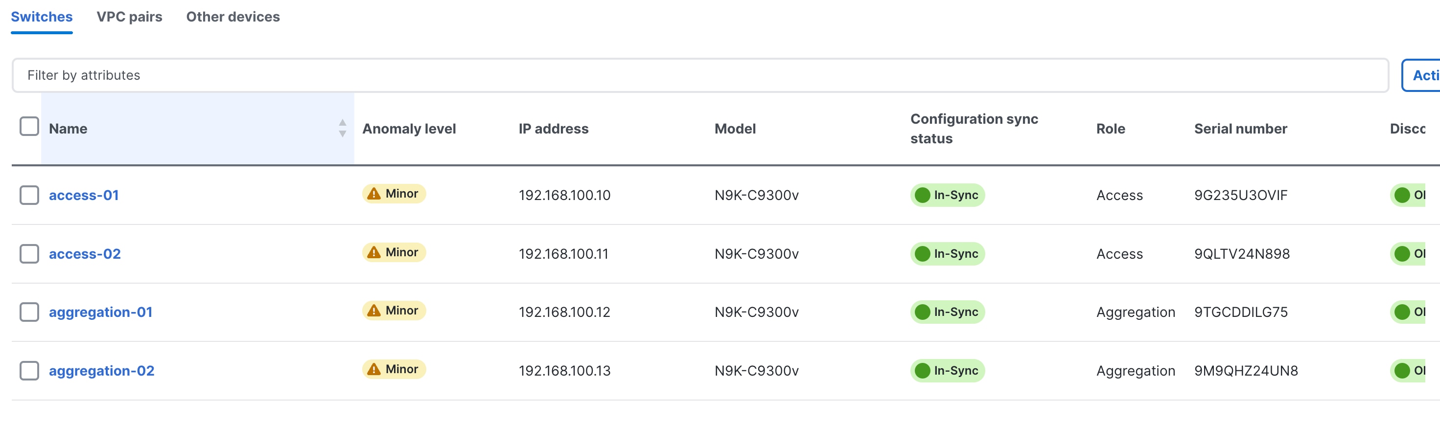
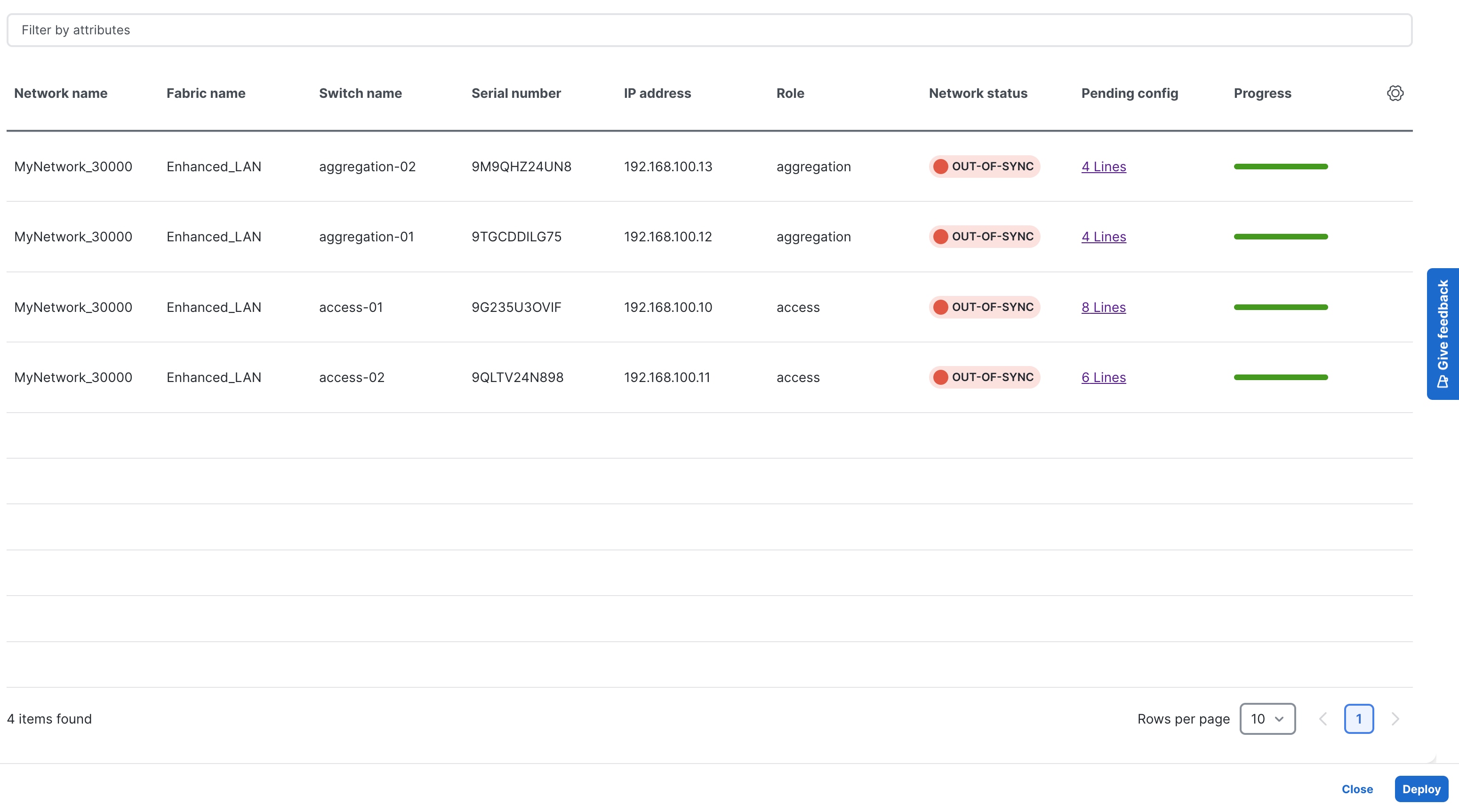
Hereafter, Configuration Compliance (CC) kicks in. Any deviation from what is intended by ND is flagged and the switch is marked as being "Out-of-Sync." This can be either a pending change that has not been pushed from ND, or an out-of-band change made using the CLI (for example). To bring it back to "In-Sync," you must deploy any pending changes at the switch level.
For an overview of the configuration compliance, see the ND Configuration Compliance video on Cisco's YouTube channel.
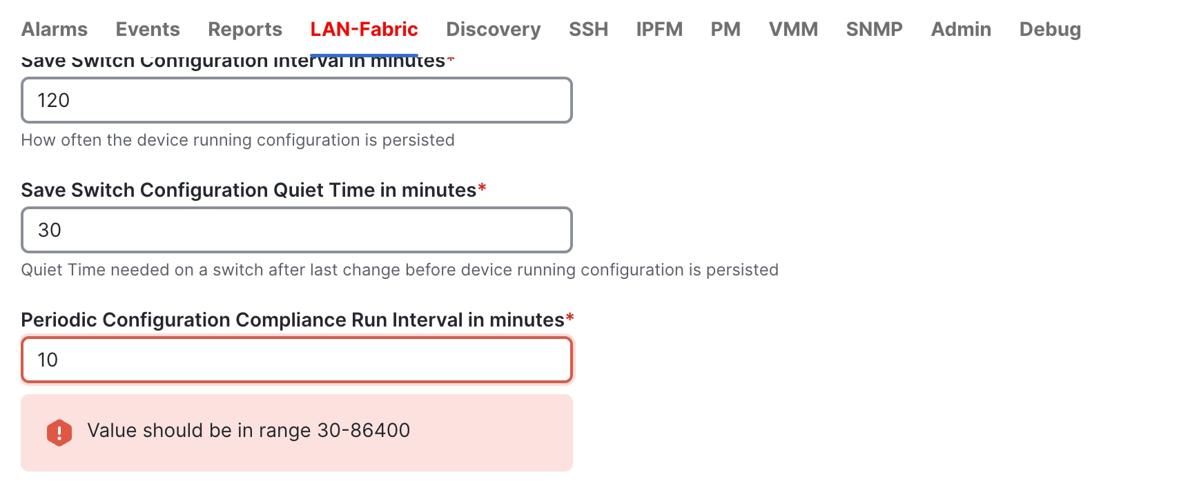
The default setting is for CC to run once every day or every 1440 minutes in 4.1.1, but you can customize CC to be run every 30 minutes up to 86,400 minutes.
Because the Core routers are not part of the Enhanced Classic LAN fabric, you import them into a fabric type called "external and inter-fabric connectivity.” For more information, see the Editing External Fabric Settings for release 4.1.1.
The process is very similar to the above, except that you use a different fabric type and a different role:
● Create fabric using external and inter-fabric connectivity template
● Discover the switch(es)
● Define role as Core
● Recalculate and Deploy
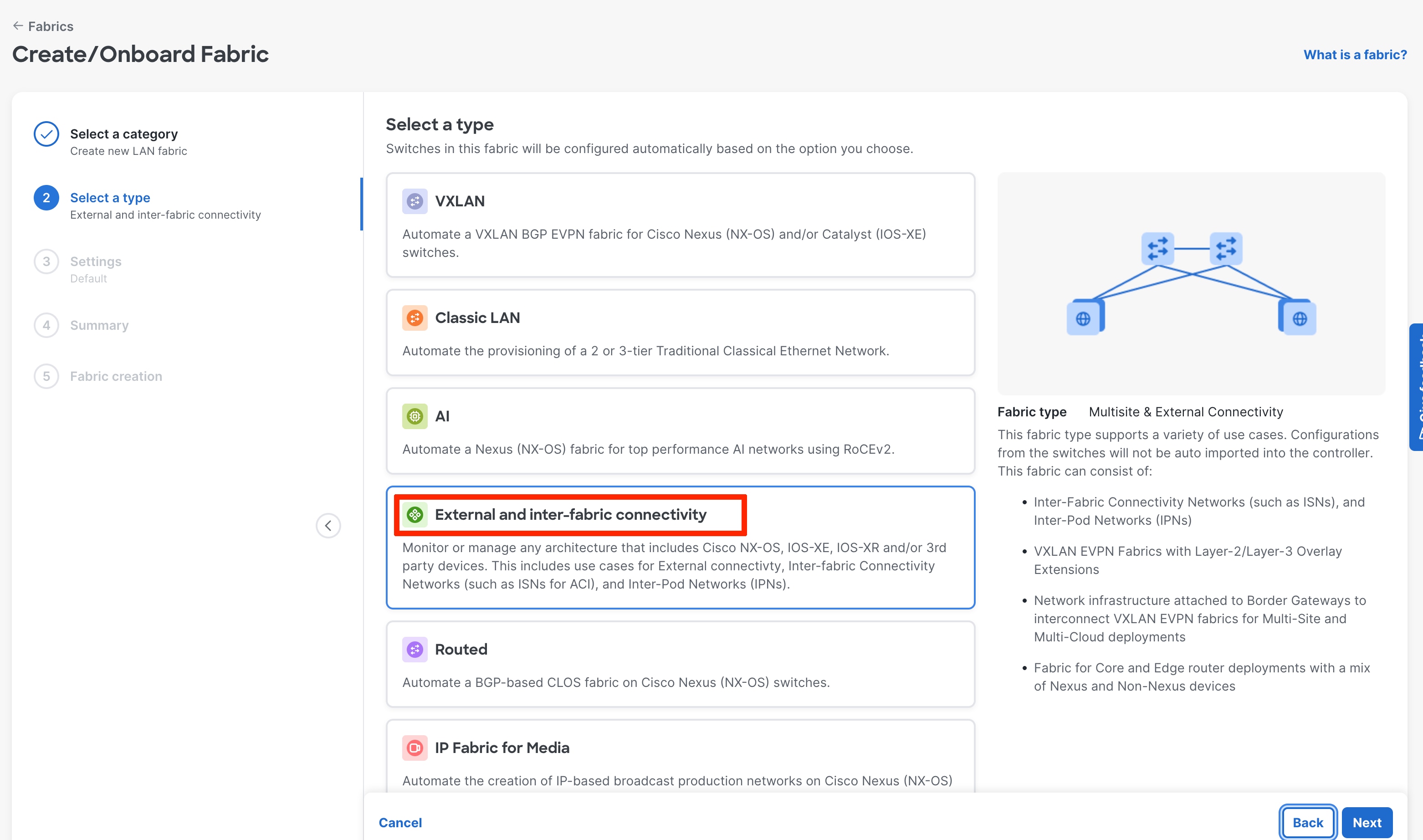
The following screenshot shows an example of creating a fabric using the External and inter-fabric connectivity fabric type:
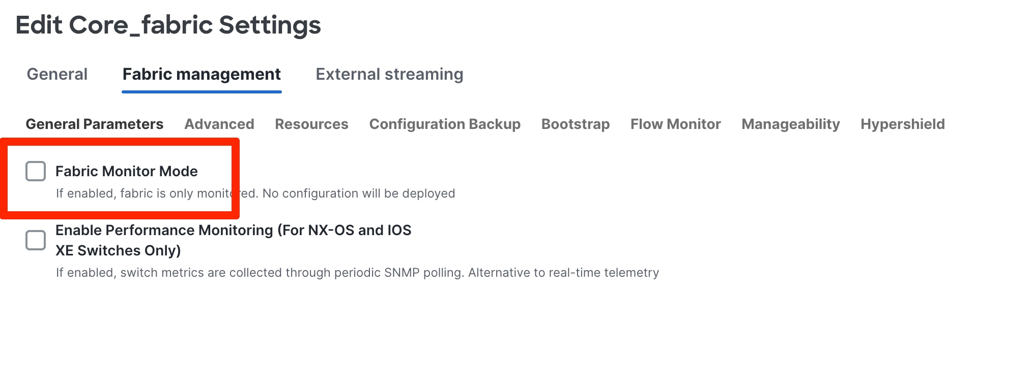
By default, in 4.1.1, the Fabric monitor mode is checked. If you want to push configuration, please uncheck the box as shown below.
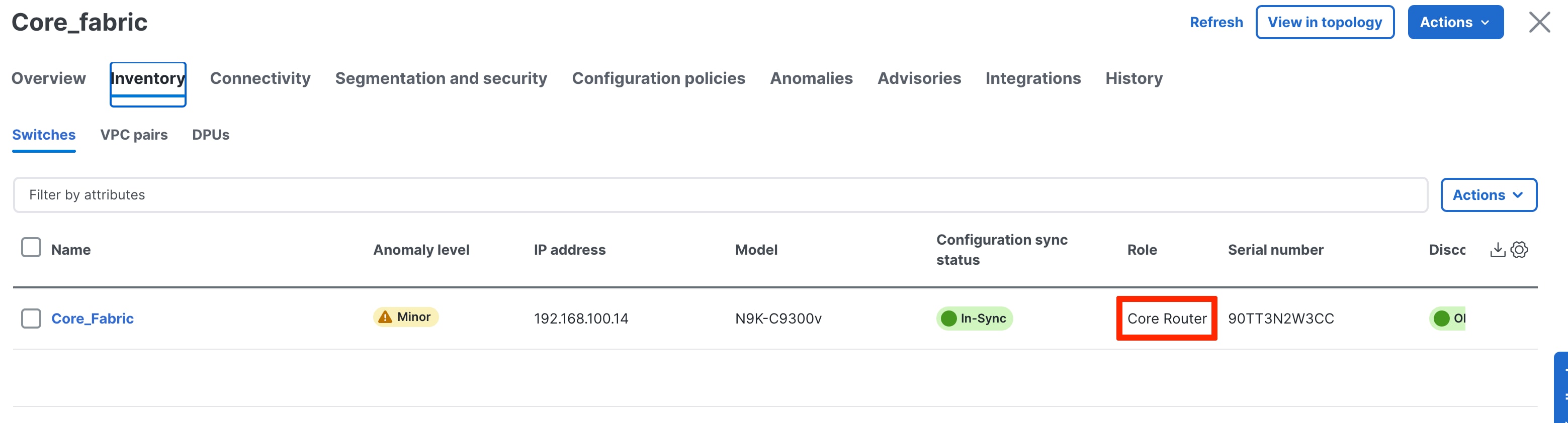
The following screenshot shows a switch defined as Core, with a Recalculate and Deploy executed:
If you require group visualization for a topological view or an option to do a group deployment for switches in different fabrics (example Core and Aggregation), you can create the Fabric Group Classic fabric type with the Access-Aggregation and Core fabrics as child members of this group. Optionally, you can add other Enhanced Classic LAN fabrics to the group. These fabrics are considered child fabrics of the Fabric Group.
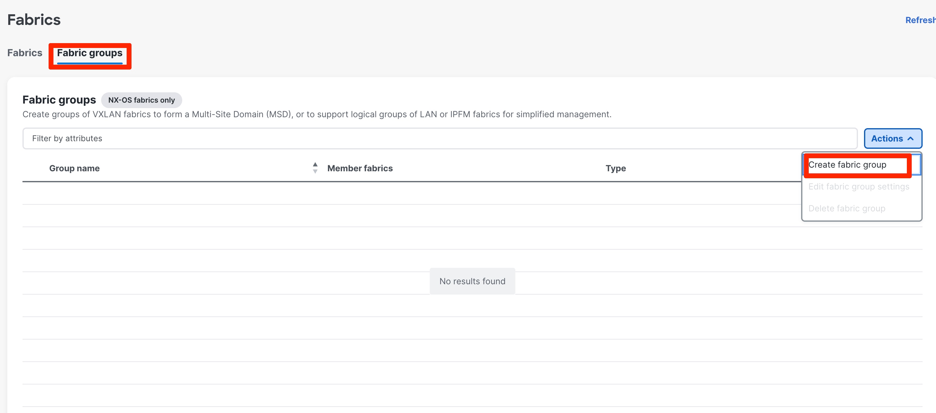
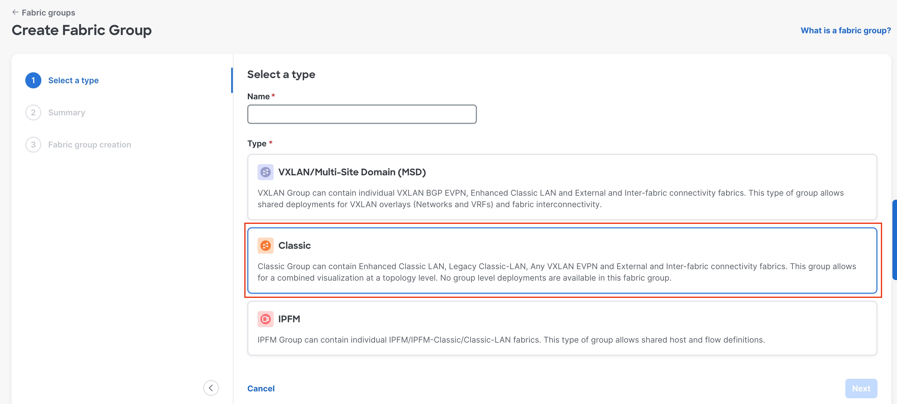
After you create the group, you must add the child fabrics:
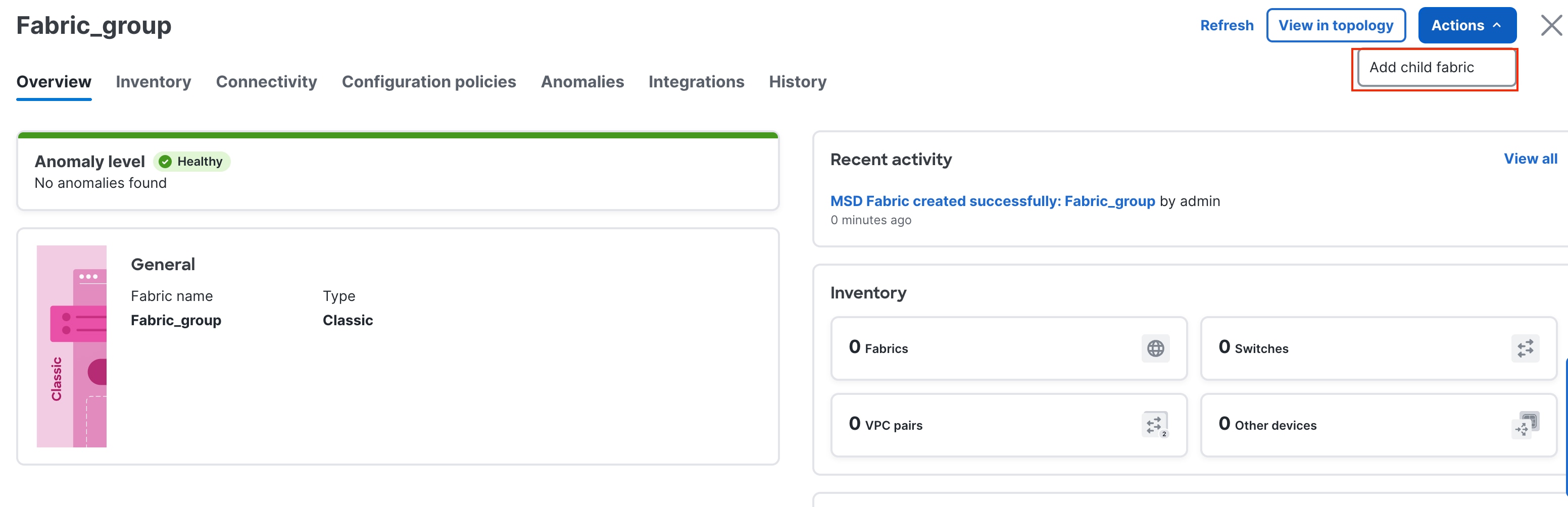
You can choose right-click operations from the Topology page per switch or fabric. From the Fabric Group, you can use a deploy option for a switch or group of switches that are part of the child fabrics, which is useful for VRF-Lite level operations as discussed in the Day 1 section.
Day 1 for Enhanced Classic LAN
After you created the fabrics with the appropriate switches and the vPC-based topology is up and running, it is time to deploy the networks and VRF instances, and provision VRF-Lite. ND supports both IPv4 and IPv6 options. Classic LAN deployments often have single or very few VRF instances.
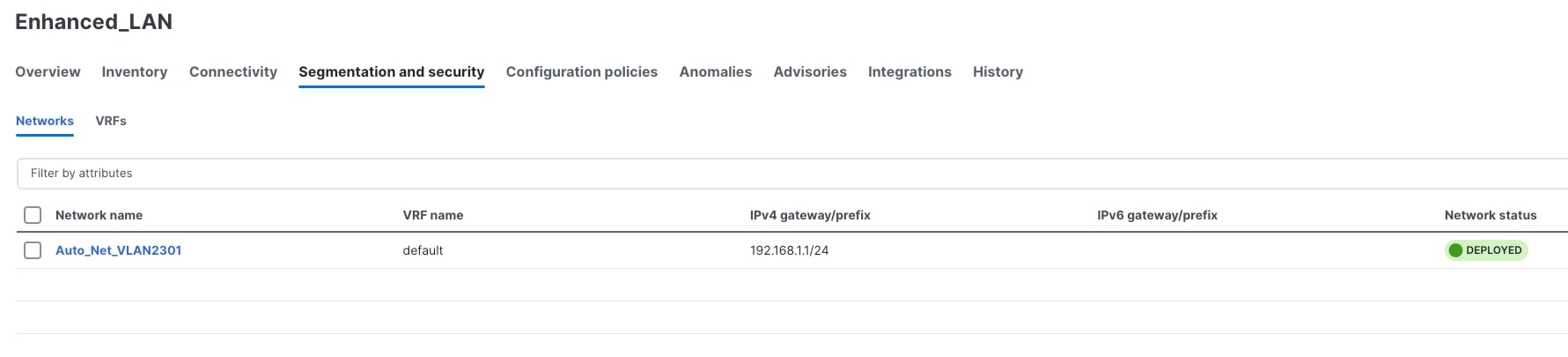
For a brownfield import scenario, the existing networks will be learned with a suffix "Auto" as shown in the following screenshot:
The existing VRF instances are learned as well, as shown in the following screenshot: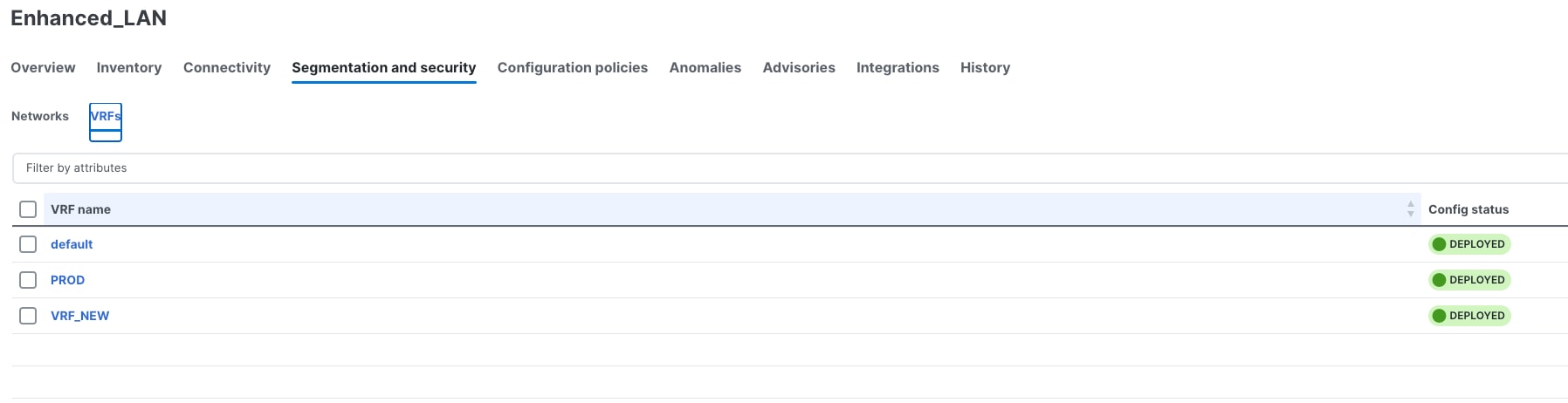
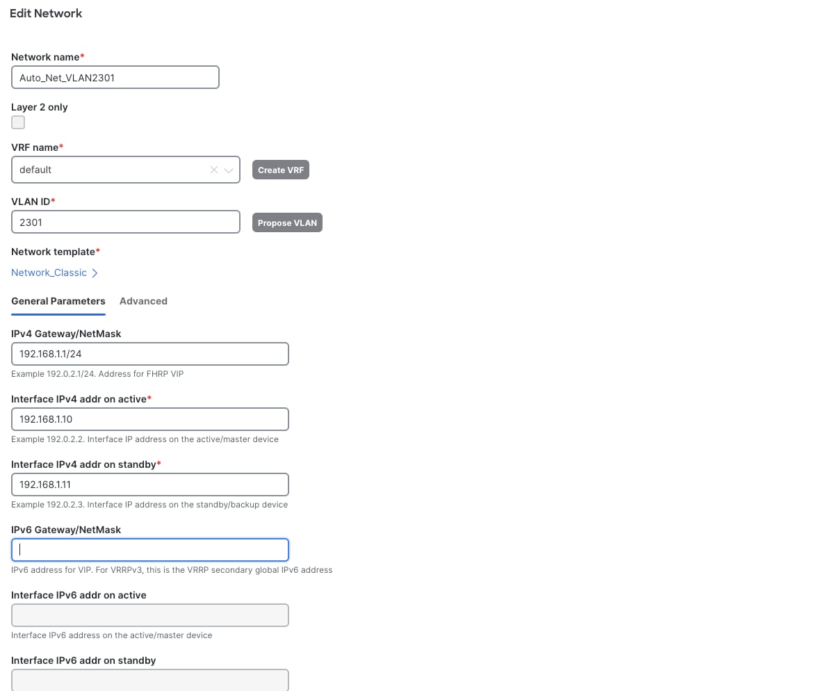
You can always perform an edit operation for learned networks and VRF instances using ND. The existing configurations have been mapped to a predefined template that provides an intuitive workflow to create or edit as shown in the following screenshot:
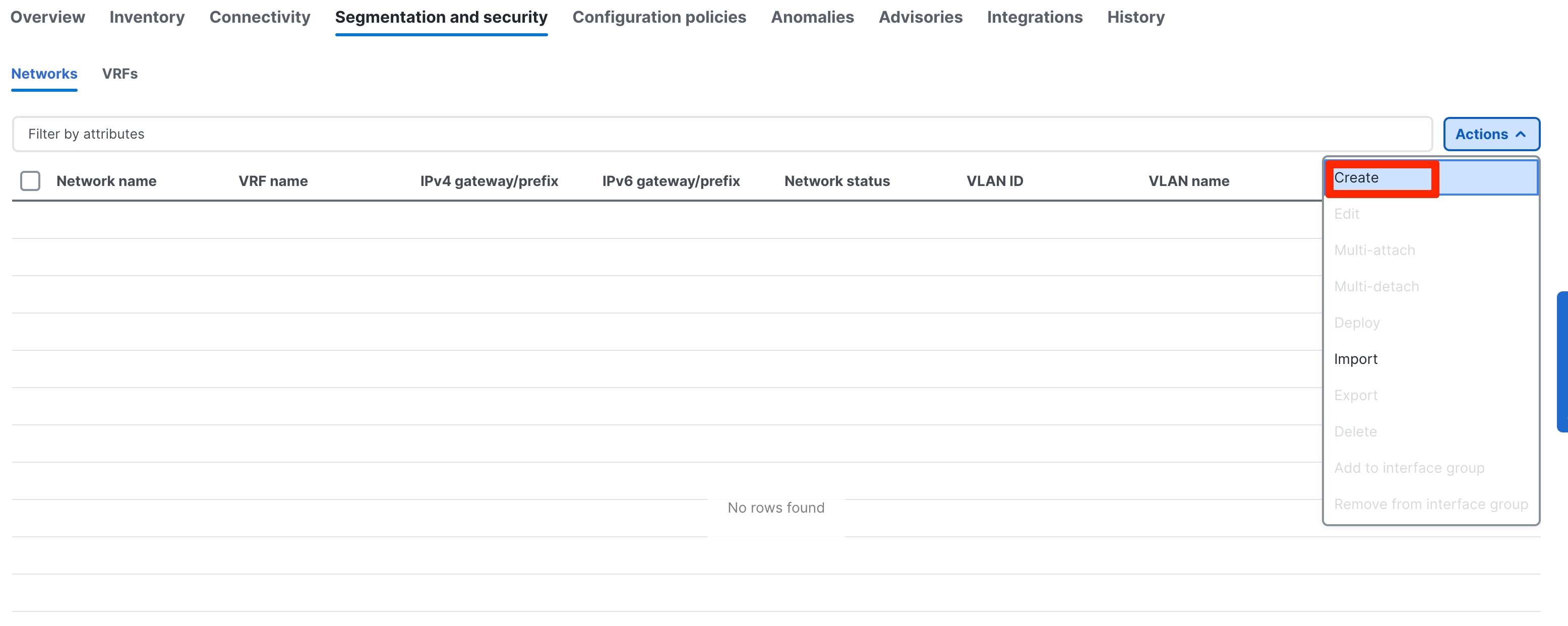
Now, let us look at the creation of new networks and VRF instances. This is applicable for both brownfield and greenfield networks.
Day 1 workflows fall in the following categories:
2. Layer 3 Network in Default VRF
3. Layer 3 Network with Custom VRF
4. VRF-Lite extension between the Aggregation and Core layers
5. VRF-Lite extension between Collapsed Core and WAN
Two new templates, Network_Classic and VRF_Classic, have been introduced to incorporate use cases for classic Ethernet.
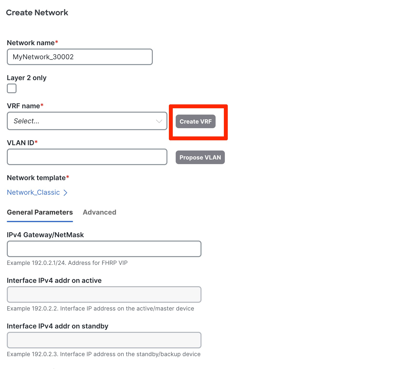
Note: Network Names and VRF Names are auto populated on creation. ND also has the "Propose VLAN" option for networks and VRF instances. You can customize all of these fields. The ND Resource Manager also tracks all these parameters, which keeps a database of used resources to avoid conflicts.
A Layer 2 network is easy to create. The gateway for a Layer 2 network resides outside of the fabric; hence, the IP addresses are left empty. You can input an associated VLAN or let ND ‘propose a VLAN based on the available resources (the range is customizable in the fabric settings).
After you create the networks, you can attach the networks to host-facing ports on the Access switch, which will thereby allow the VLAN on these Trunk or Access ports, and on the vPC, port channel, and standalone ports between the Access and Aggregation layers.
You only need to specify intent to attach networks on host-facing ports. All the other interfaces between the Access and Aggregation layers as well as the Aggregation layer will automatically inherit the respective VLANs to allow end-to-end communication without you having to define this explicitly, making the operation trivial.
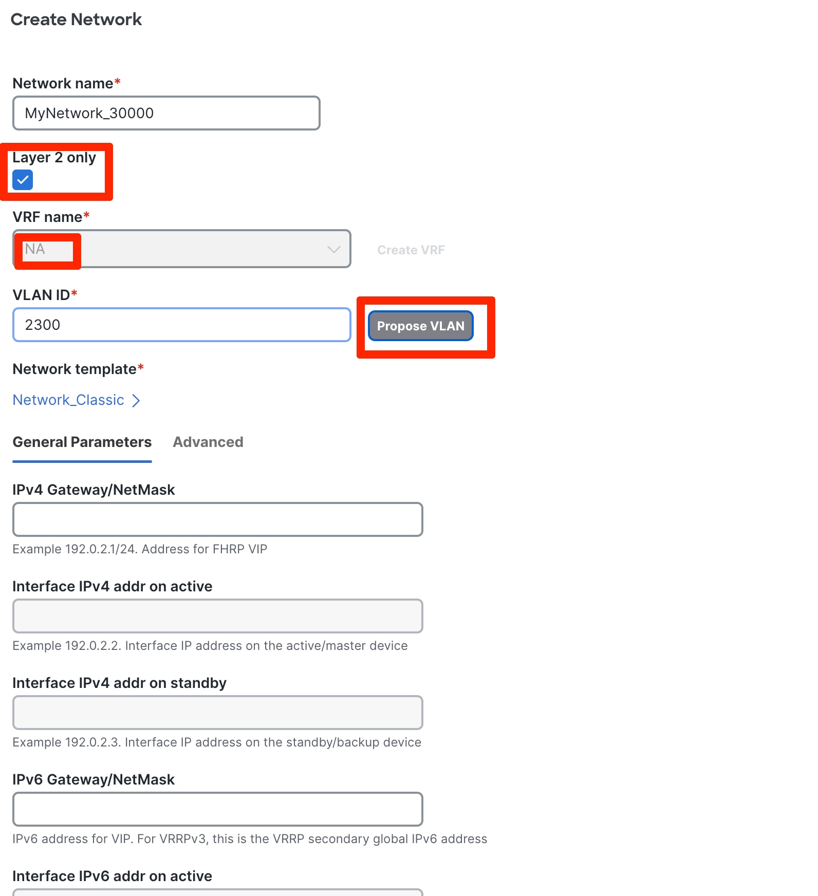
Advanced settings include adding DHCP relay server information and editing the default HSRP/VRRP settings.
Note: You cannot change the FHRP protocol from HSRP to VRRP or back from this screen. These are inherited from fabric settings.
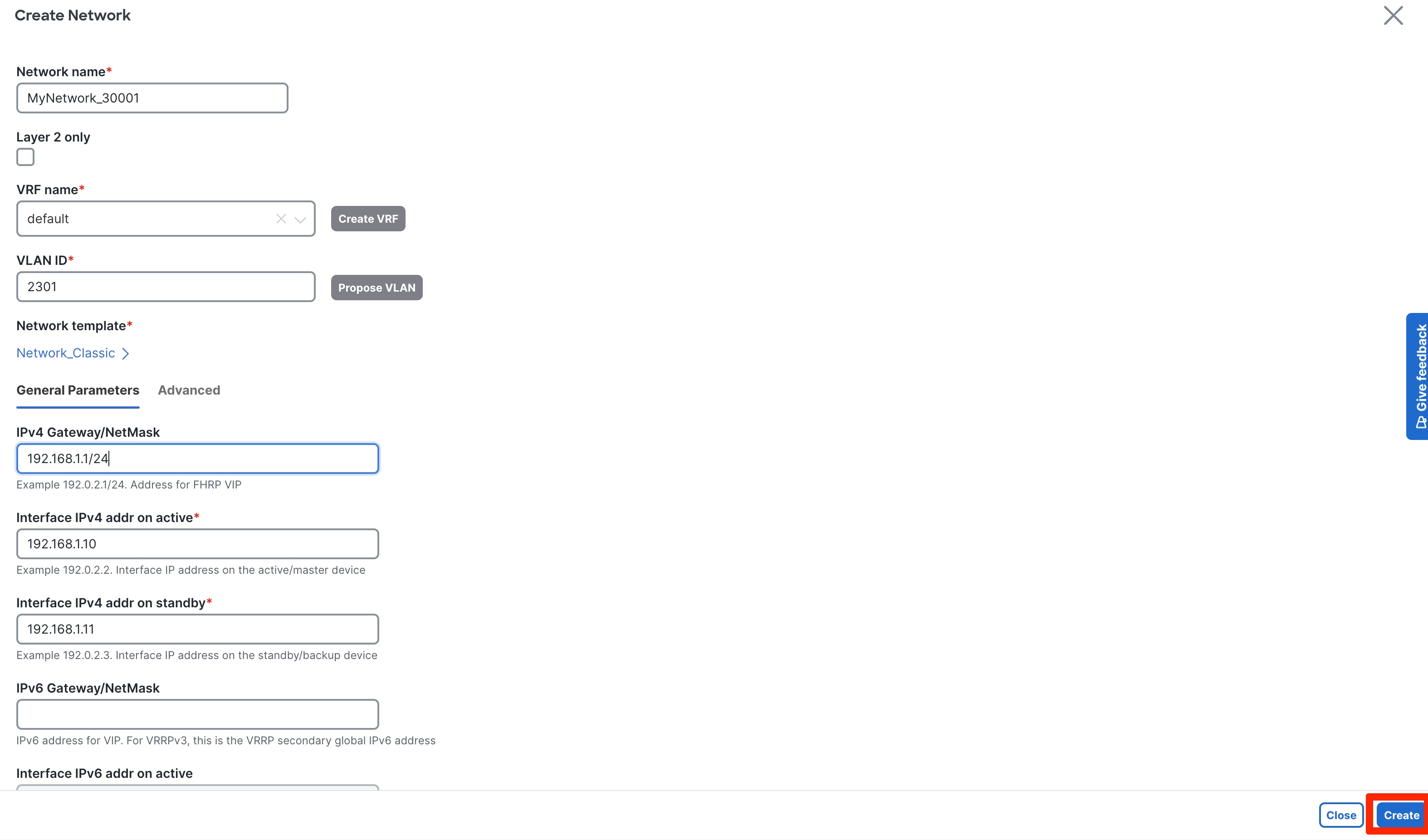
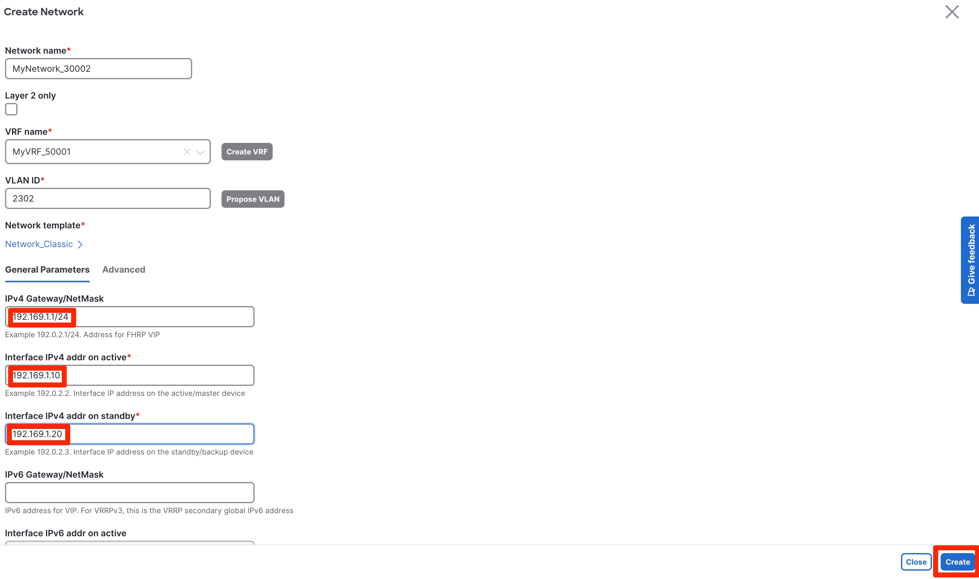
Once all the settings have been configured, click Create to create the network.
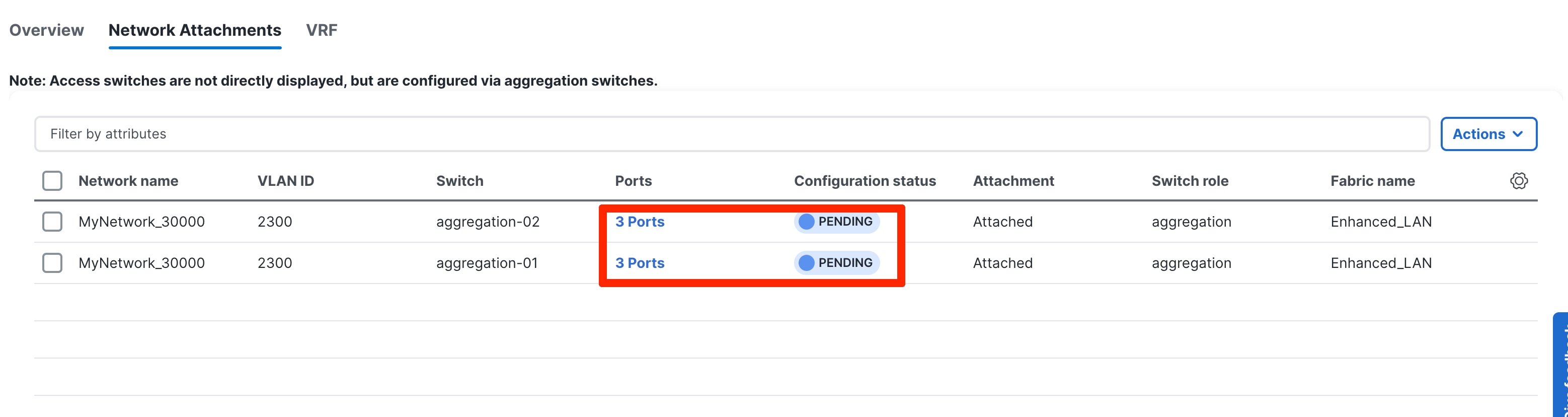
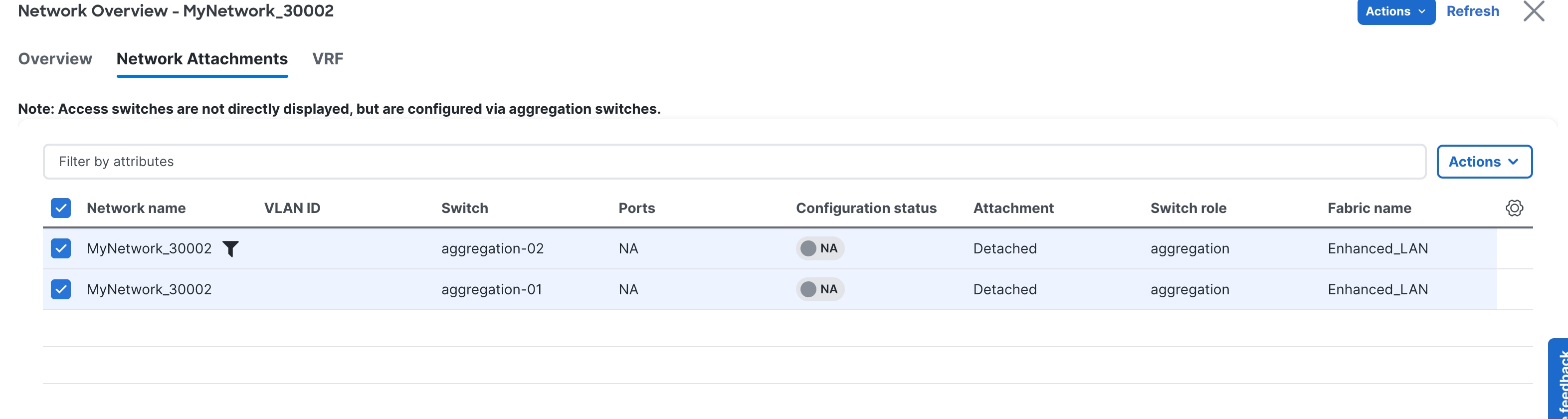
Click in Network and then Network attachment.
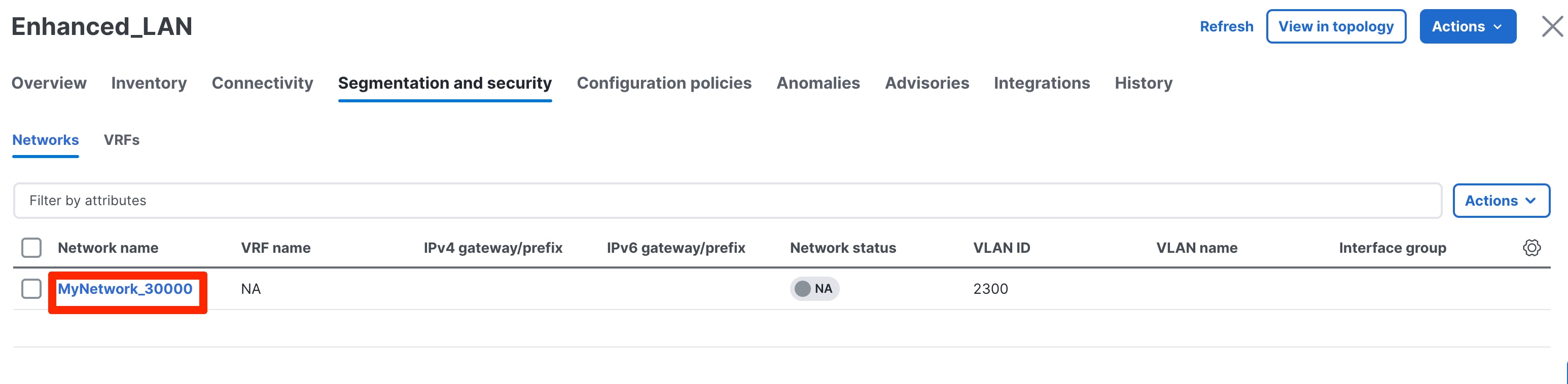
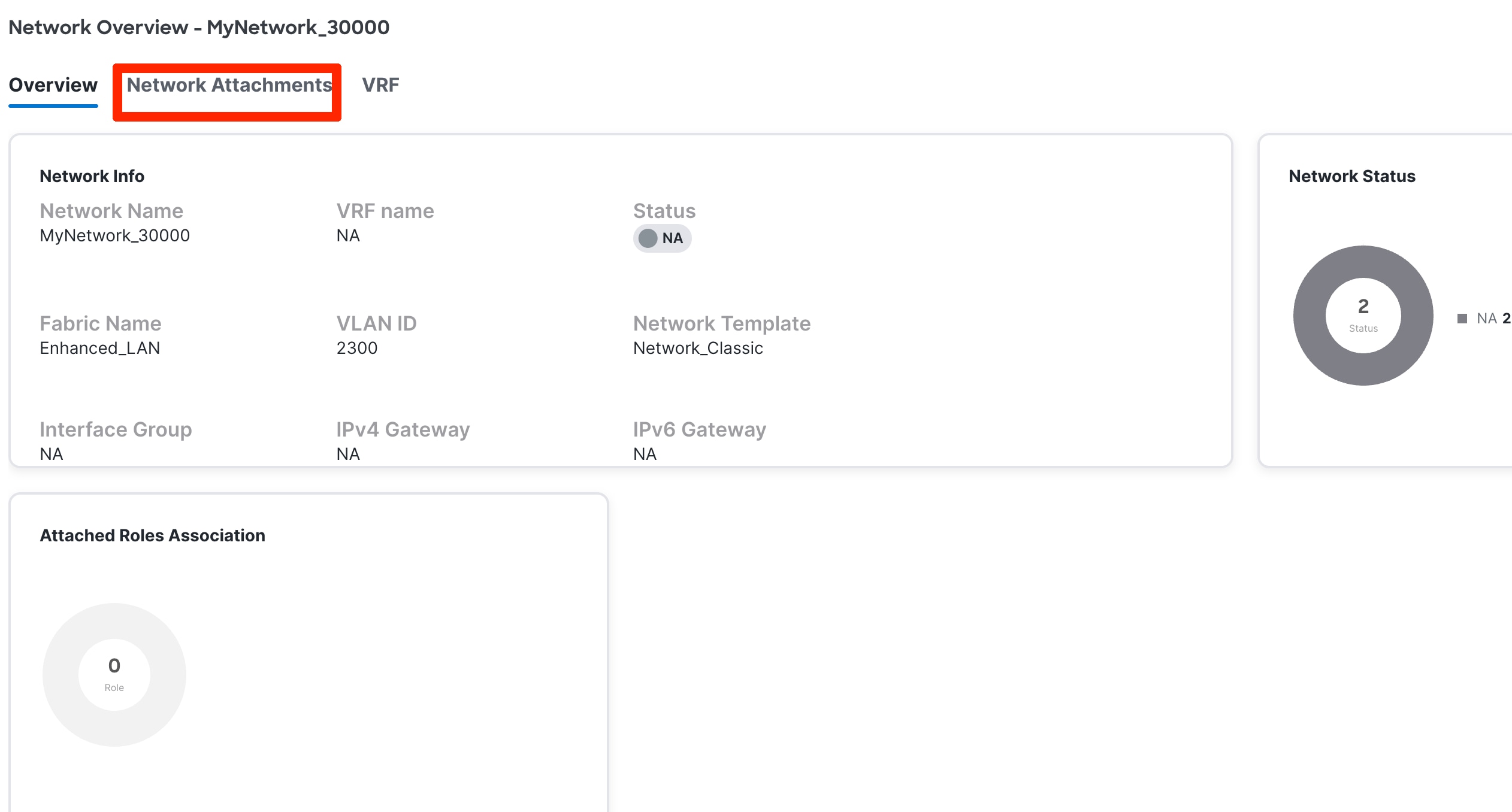
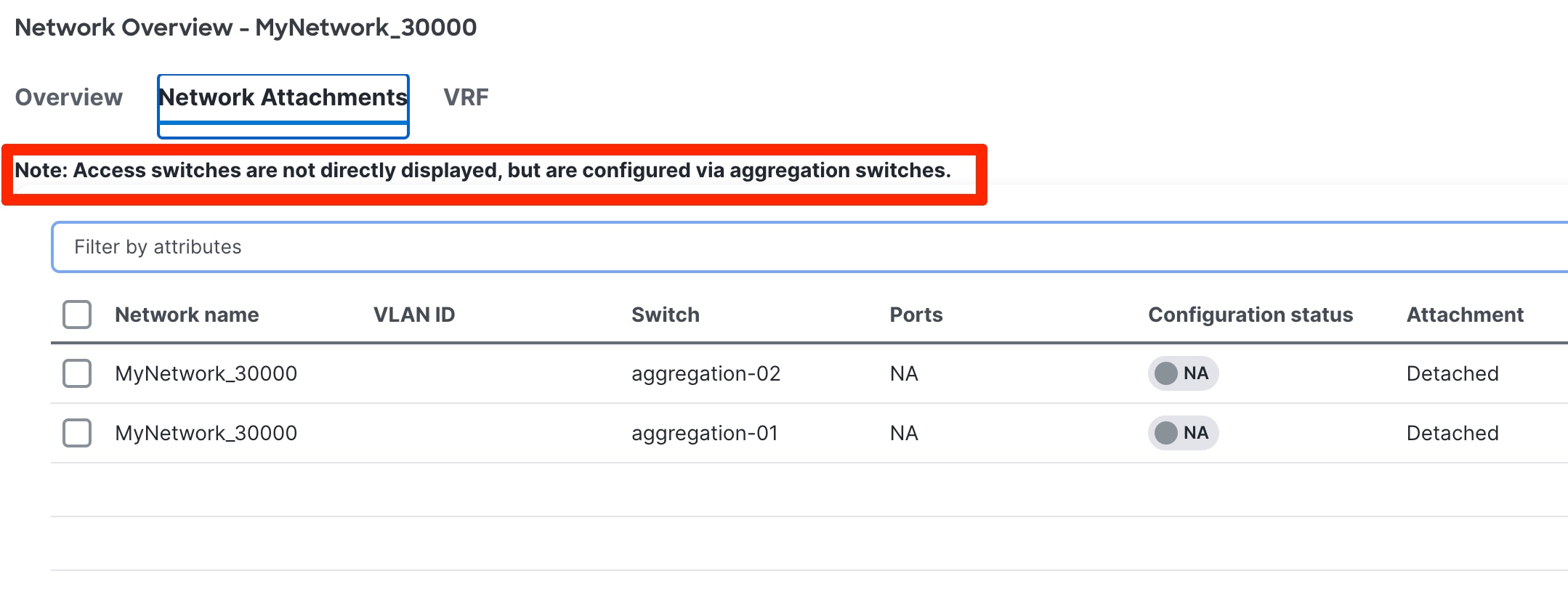
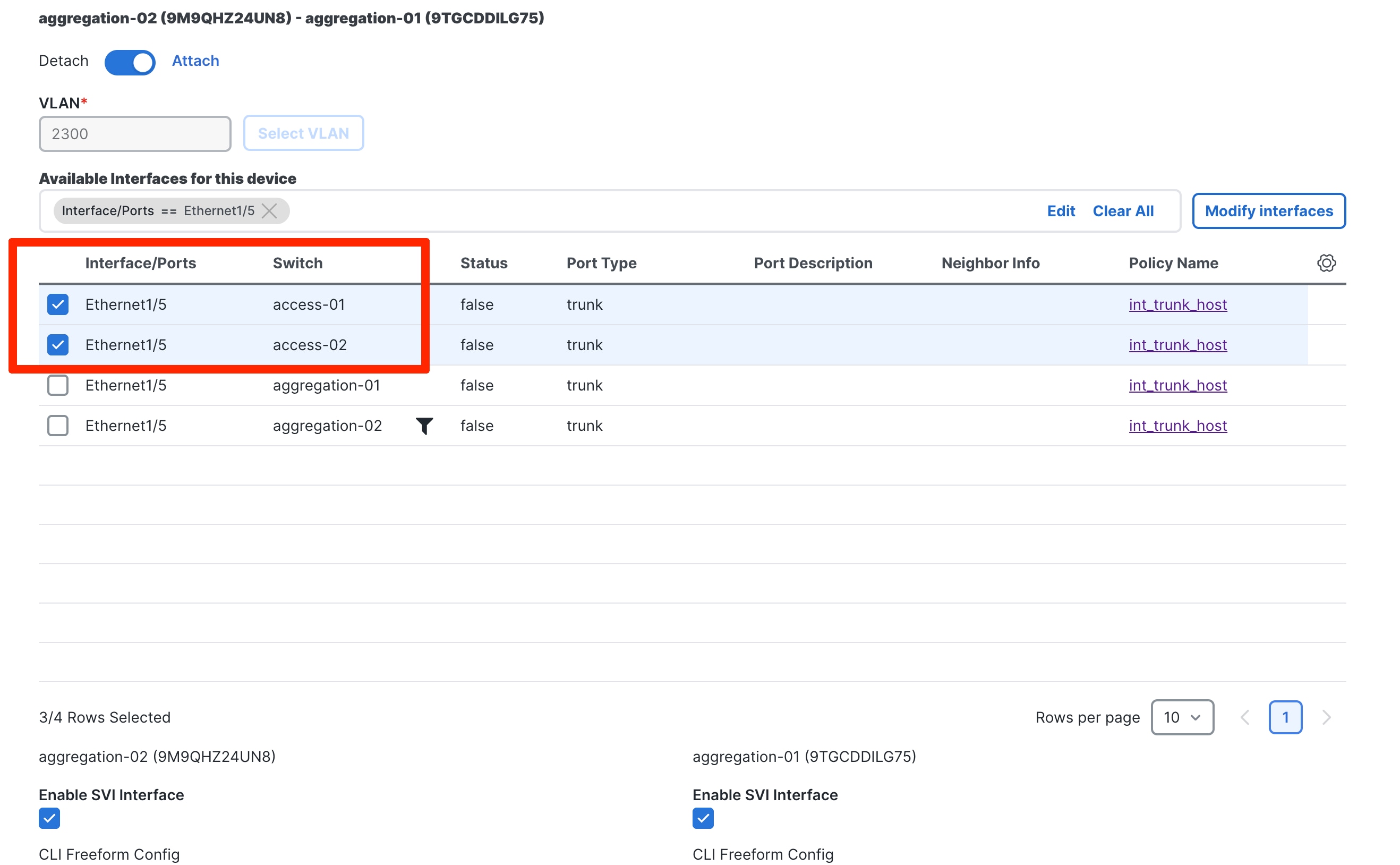
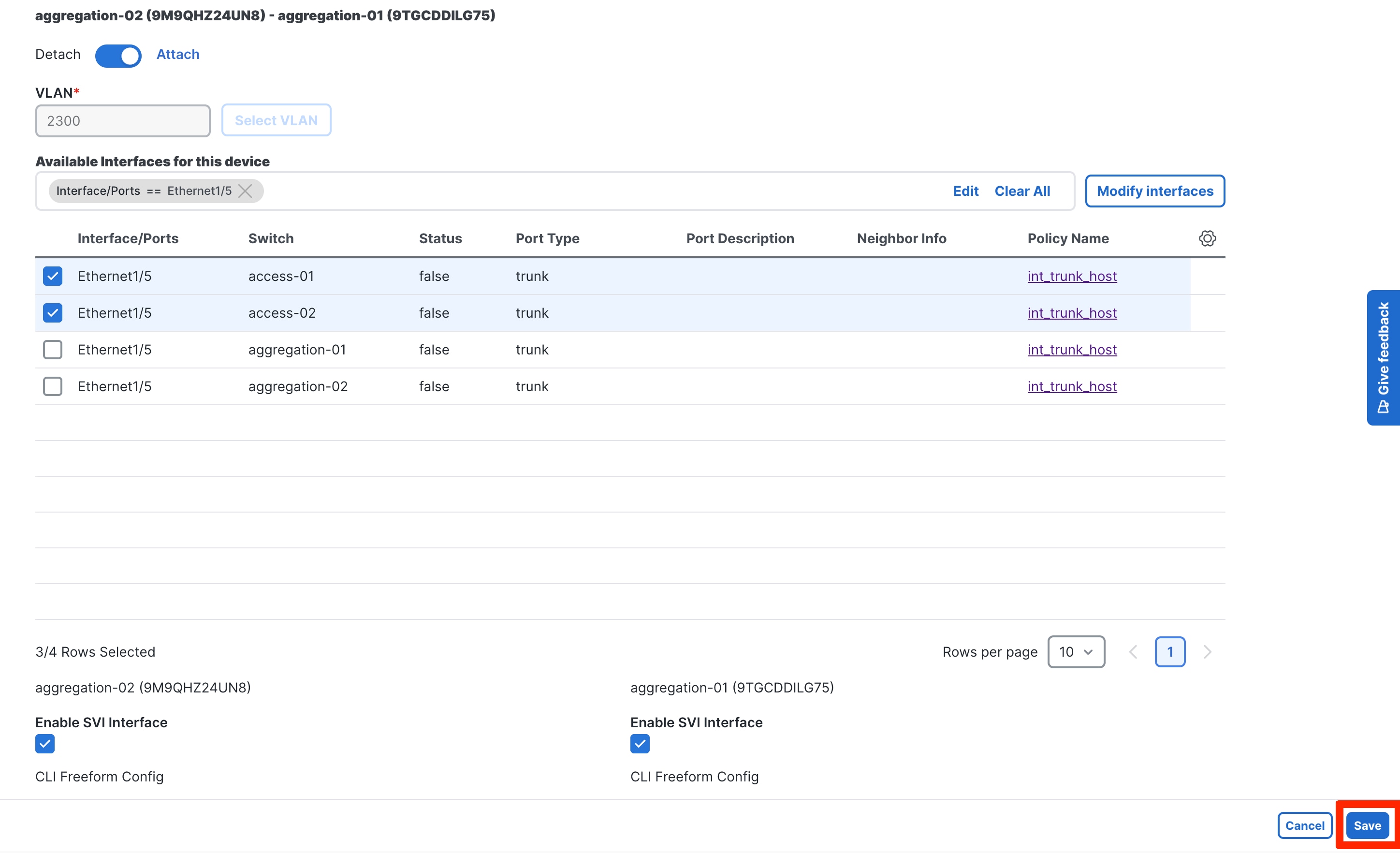
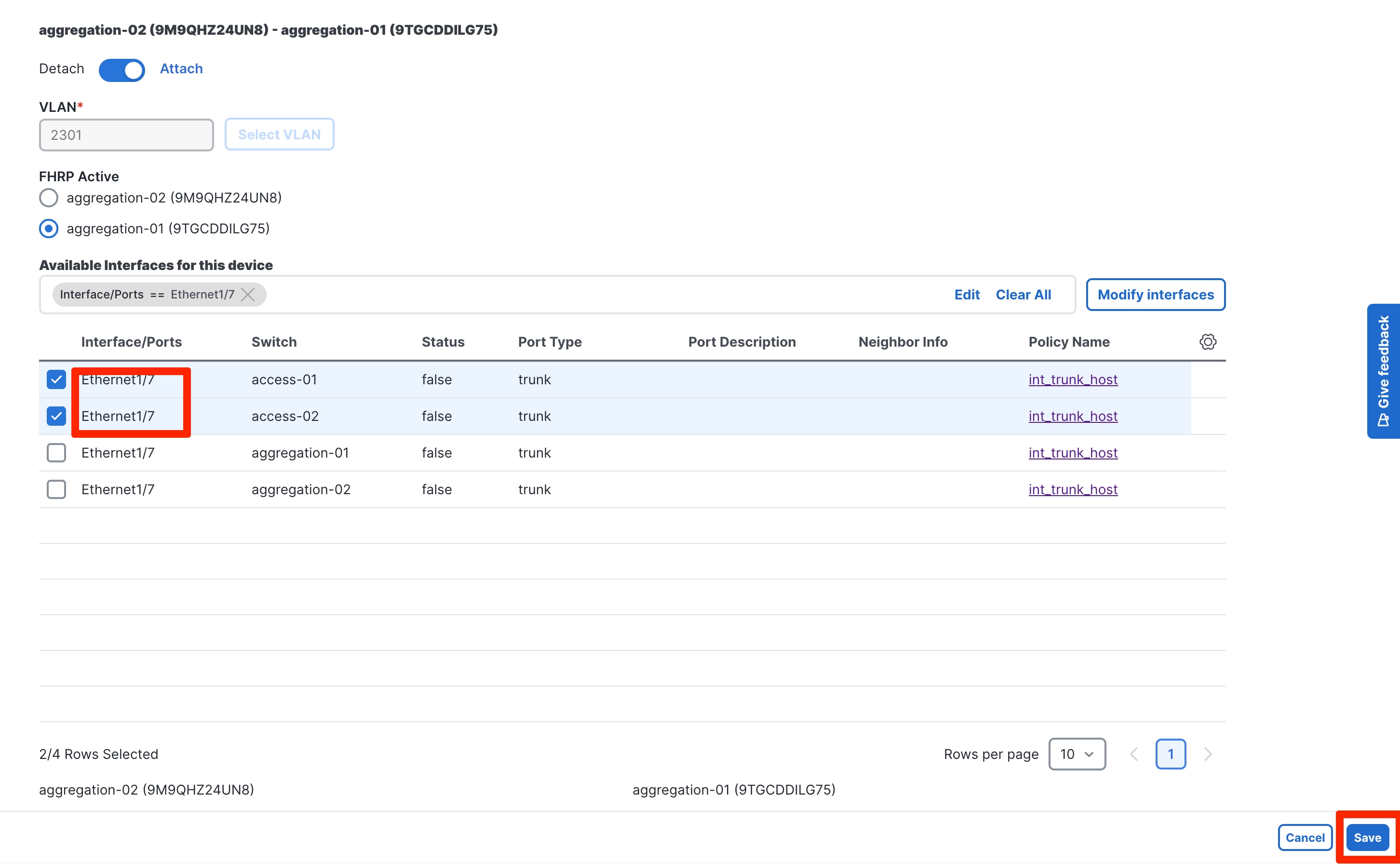
You attach the networks to the host-facing interfaces of the Access switches by selecting the Aggregation switches where the Access devices are connected. The Access switches will be connected to a unique pair of Aggregation devices, and the host VLANs must be allowed to the Aggregation. Hence, Network attachments begin by selecting the respective Aggregation pair.
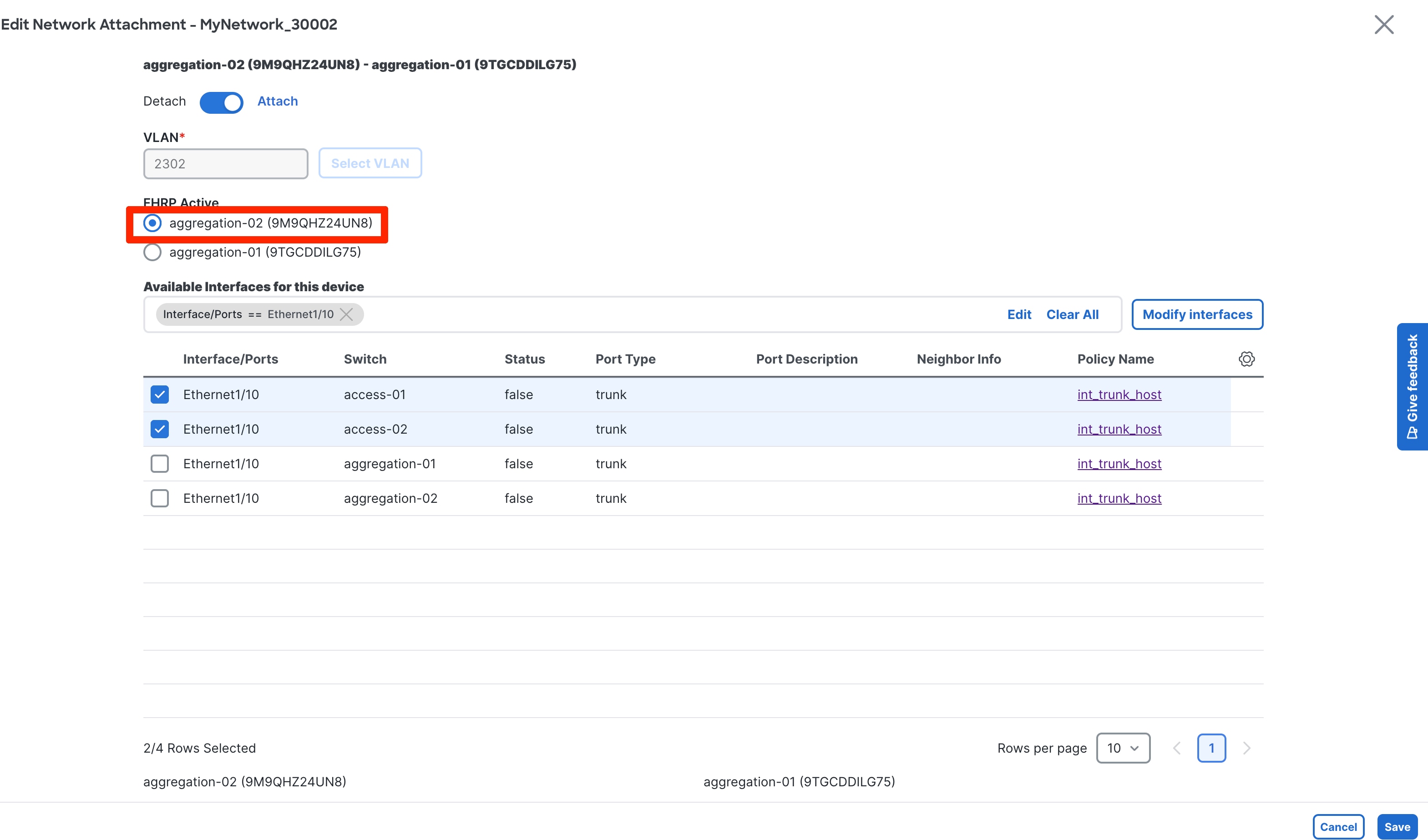
You must select the Access ports of interest for the network attachment as a next step. The uplink from Access and downlink from Aggregations will thereafter be auto configured. ND handles various topologies, including B2B vPC.
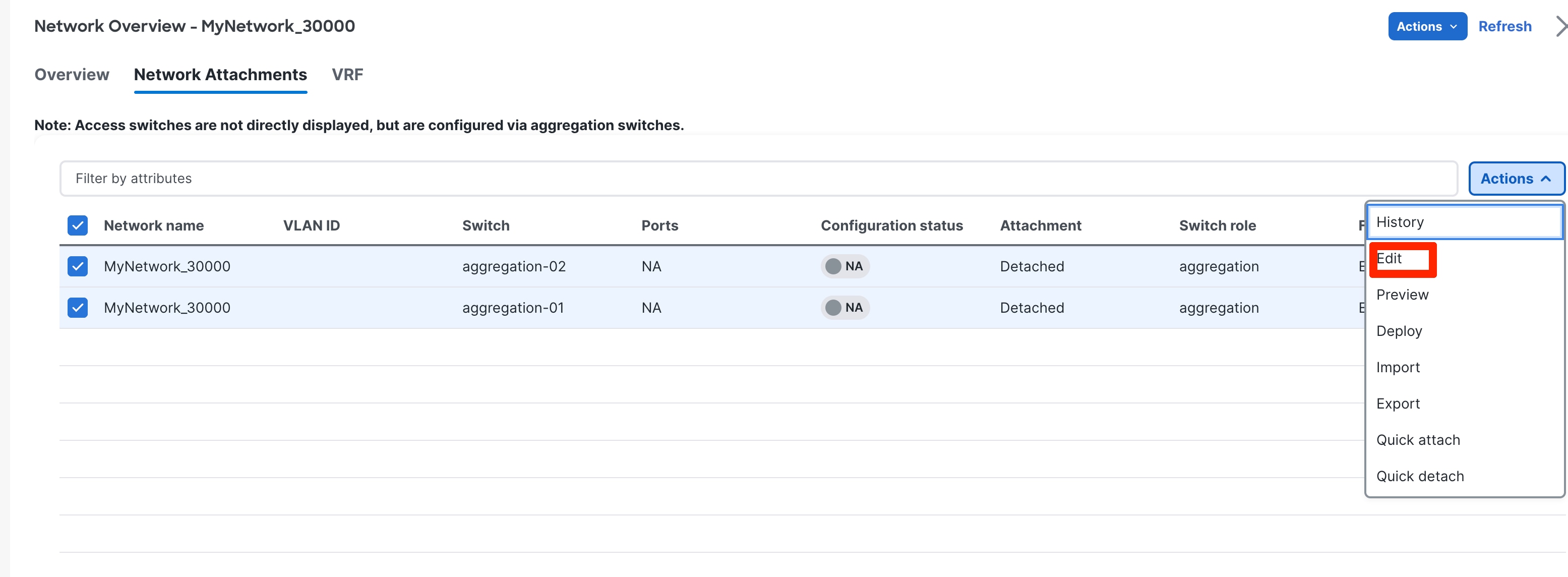
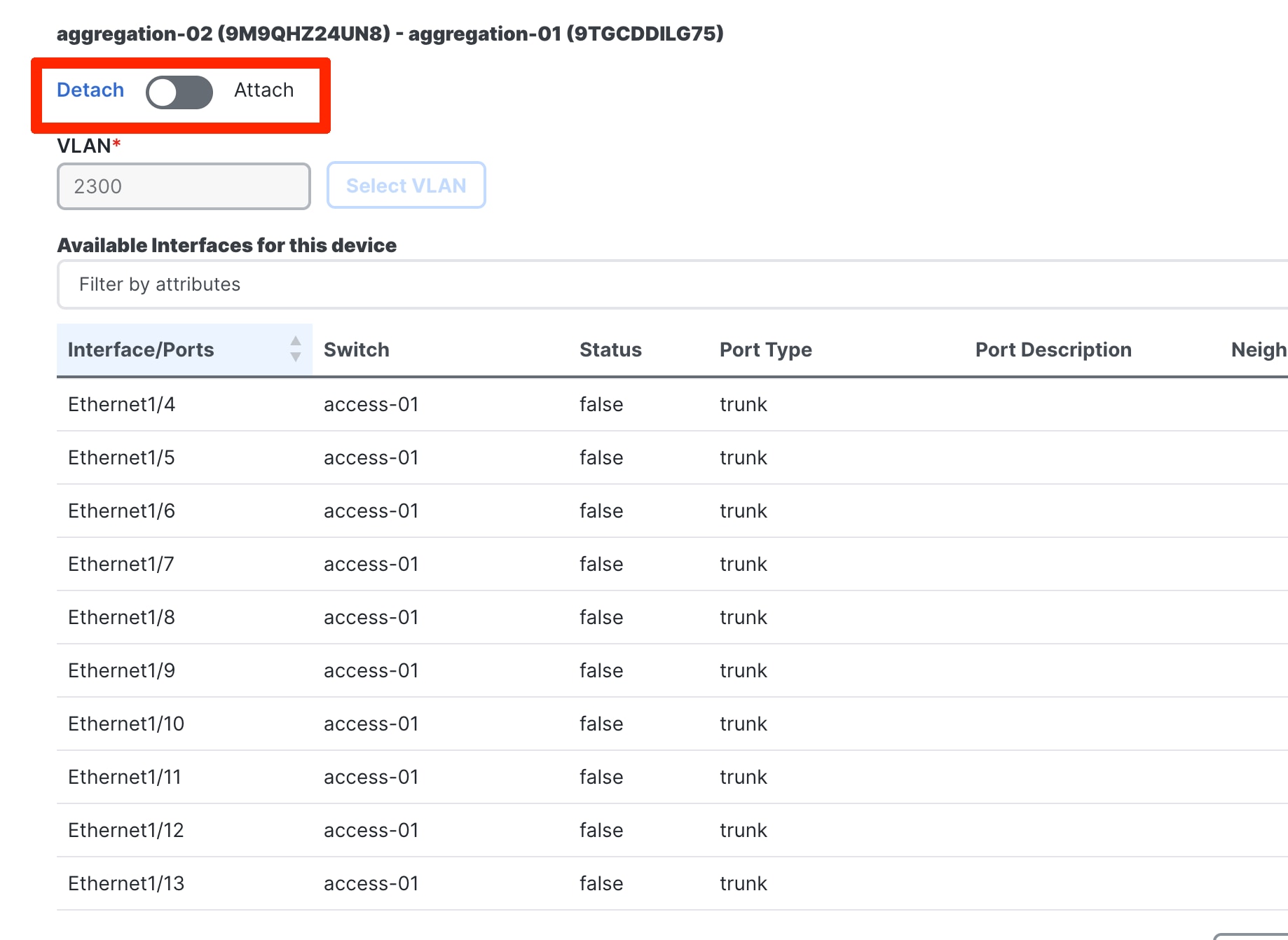
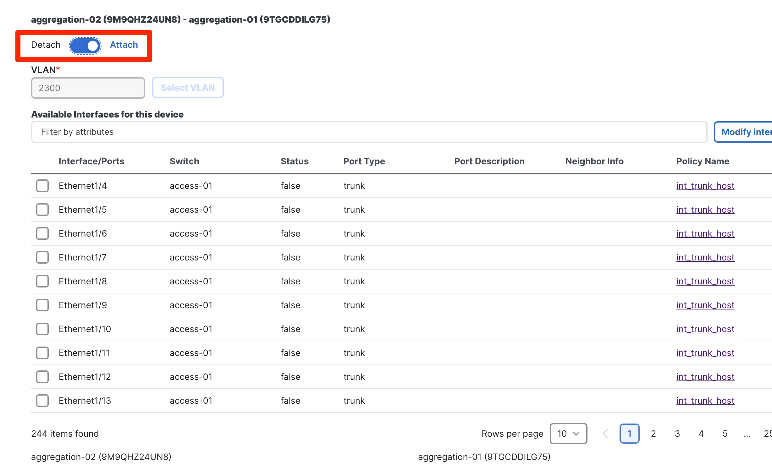
To attach the network, select the Network and Under Actions ->Edit. Toggle to Attach
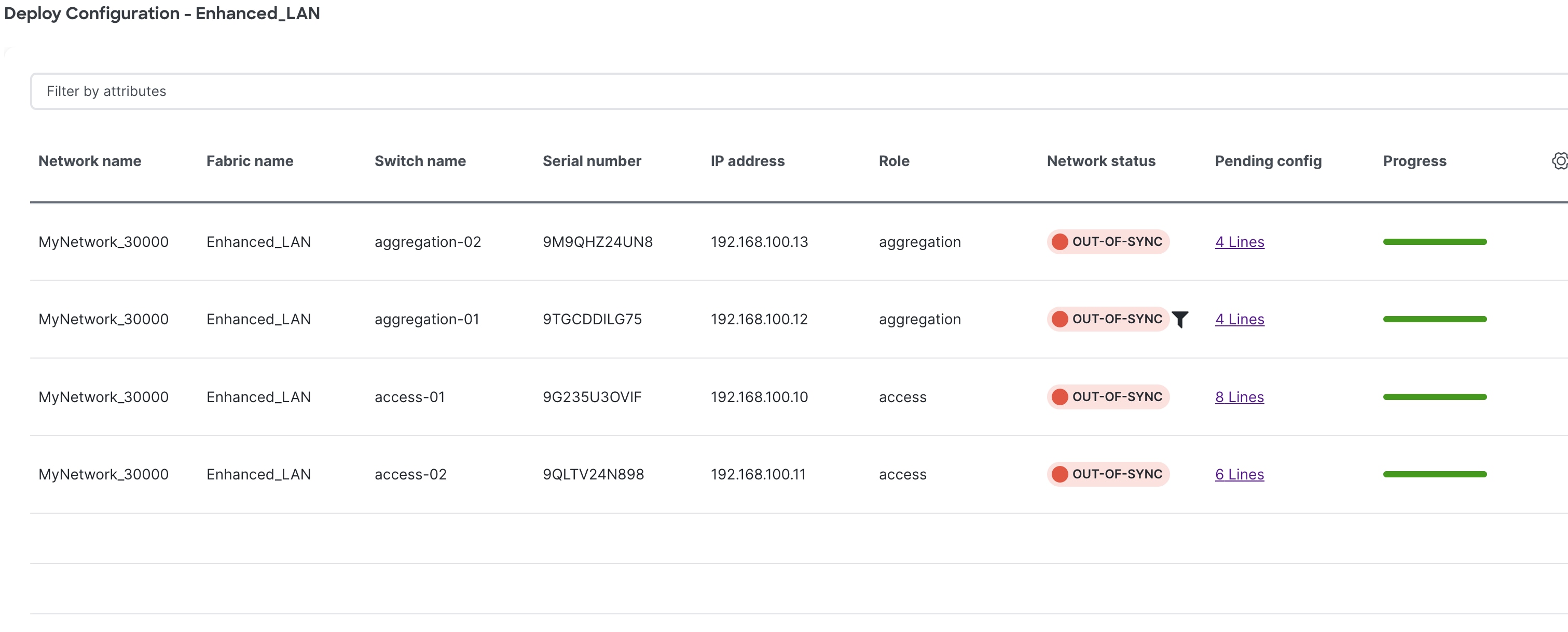
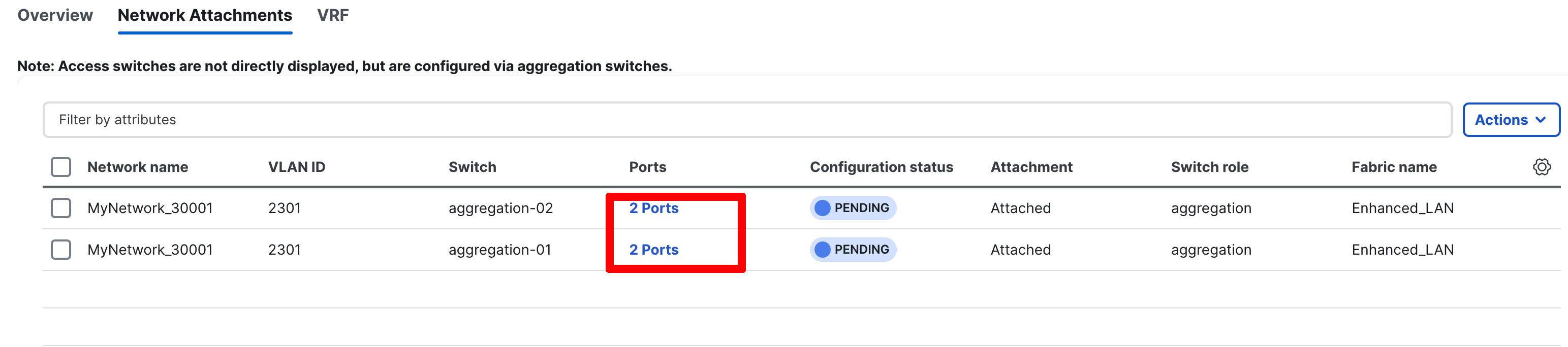
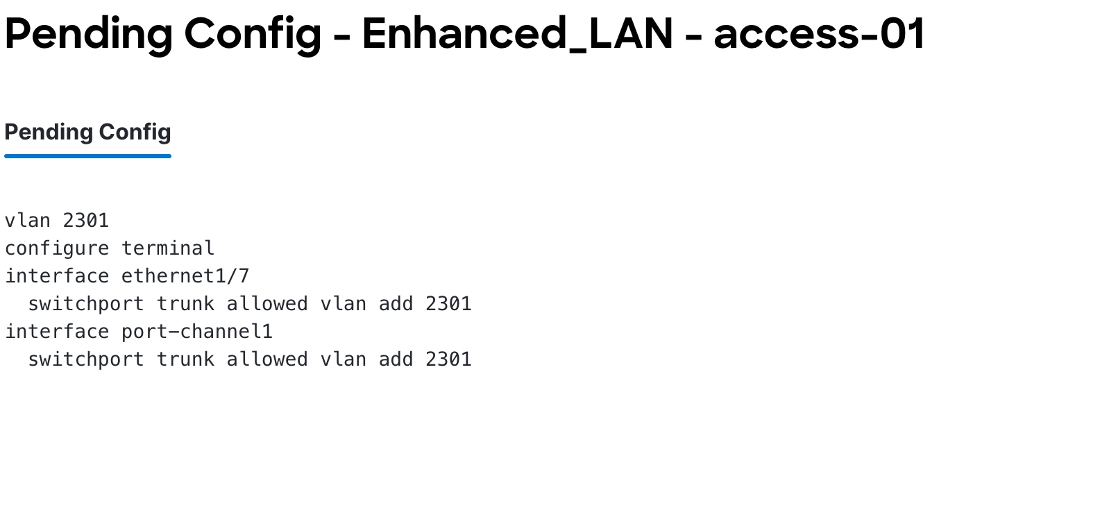
Step 3: Review Pending Configurations on Access and Aggregation
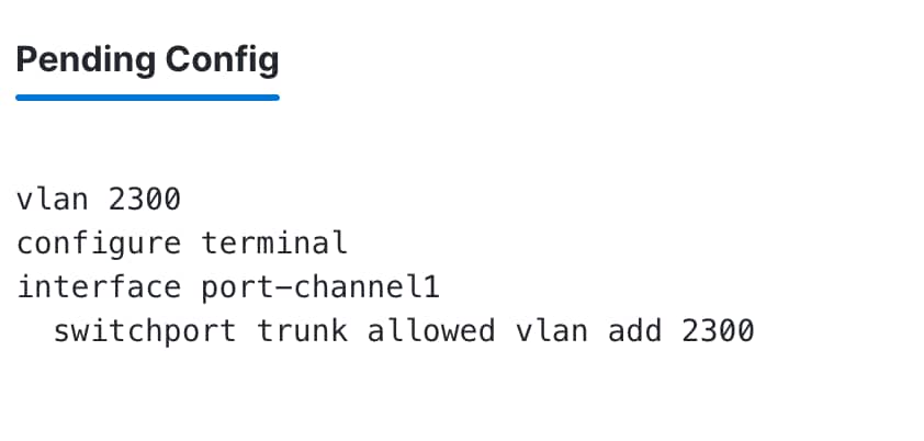
This step includes allowing the VLAN on the host-facing port on the Access and the port channels between the Aggregation and Access layers.
The following screenshot shows the pending configurations for Aggregation1:
The following screenshot shows the pending configurations for Access 2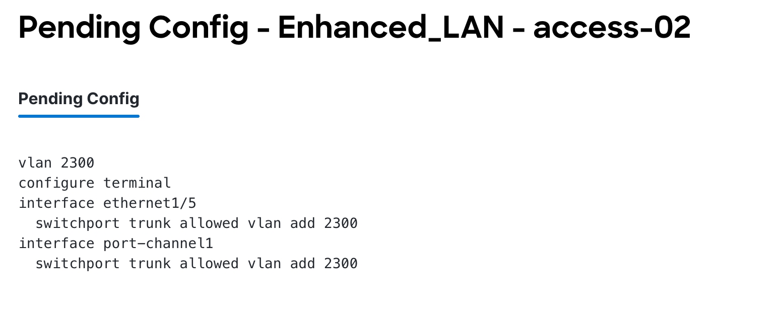 :
:
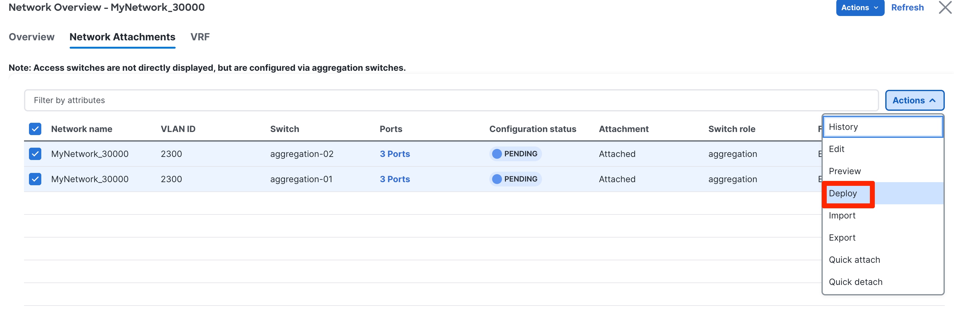
Step 4: Deploy the Configuration
Layer 3 Network in the Default VRF Instance
A Layer 3 network can either be in a default or custom VRF instance. This section creates and attaches a Layer 3 network to a default VRF instance. You must define the v4/v6 gateway virtual IP address. The IP addresses for FHRP active and standby must be defined for the network under General Parameters. This time the gateway for the network is the Aggregation switch (or Collapsed Core) within the Enhanced Classic fabric.
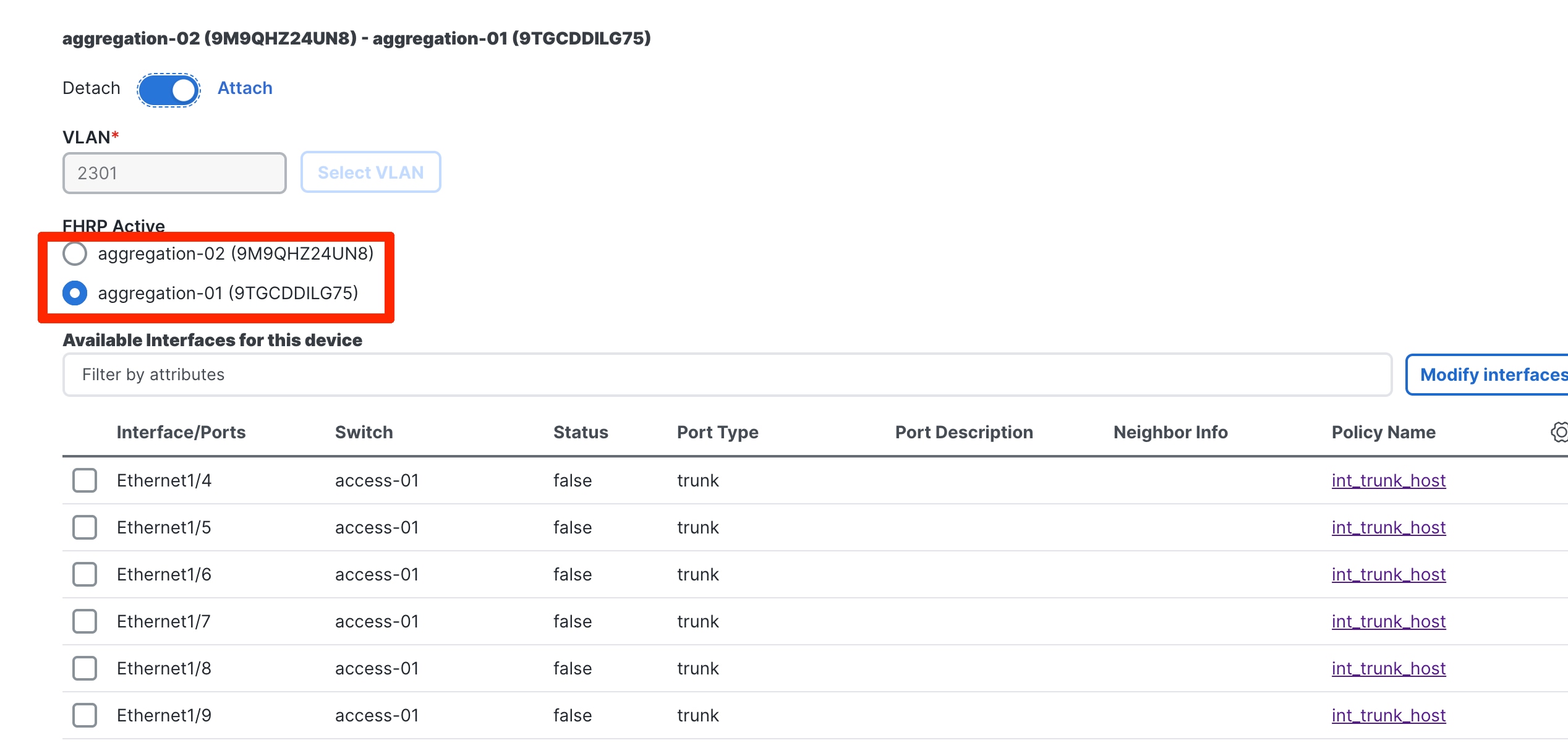
You can choose the Aggregation switch that will be the FHRP Active during the network attachment. ND auto-selected a default value based on hashing.
You can customize FHRP settings under the Advanced tab. Based on the fabric settings, you can choose either HSRP or VRRP.
The advanced settings are the same as described in the Layer 2 Network section.
Step 2: Attach the Network and Choose the FHRP Master per Network
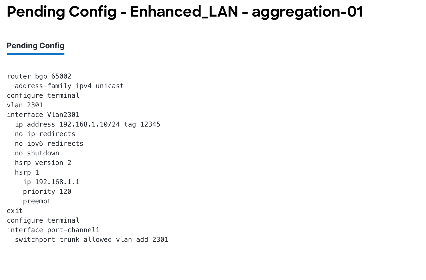
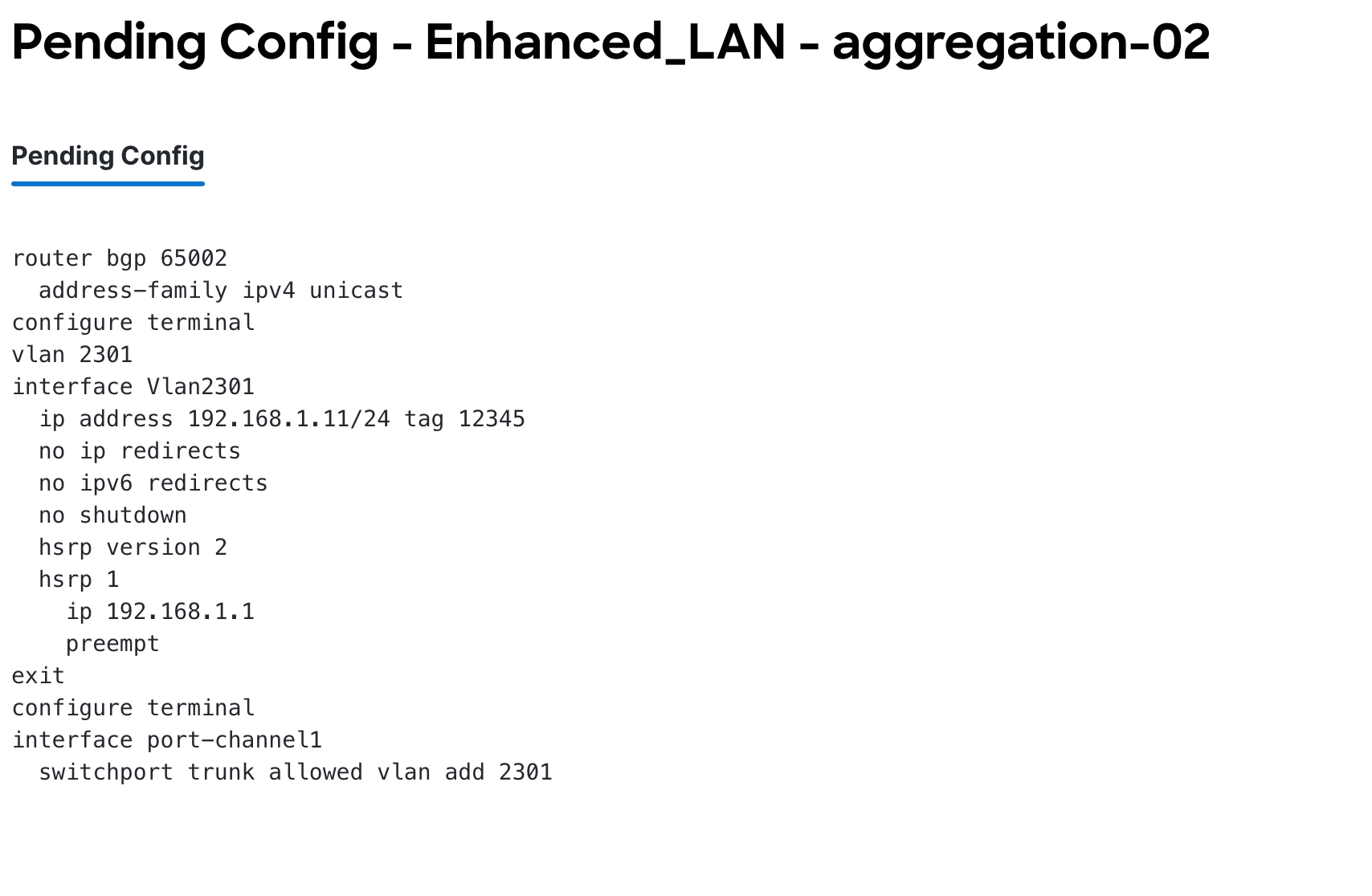
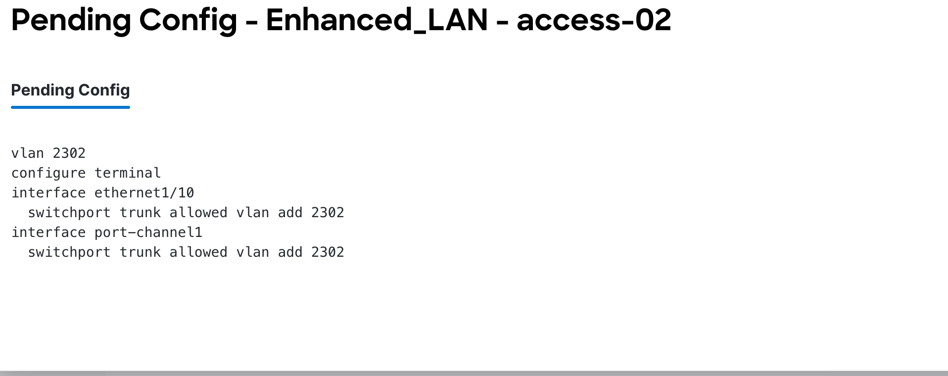
Step 3: Review Pending Configurations on the Access and Aggregation Layer
This includes allowing the VLAN on the host-facing port on the Access layer and the port channels between the Aggregation and Access layers. For Aggregation switches, in the case of a Layer 3 network, the configurations additionally include creating an SVI with the HSRP configurations, with lower priority for FHRP Active. The gateway and HSRP active/standby IP addresses used here are per-user inputs when creating a network.
The following screenshot shows the pending configurations for Access1:
The following screenshot shows the pending configurations for Aggregation1 and Aggregation 2:
Step 4: Deploy the Configuration
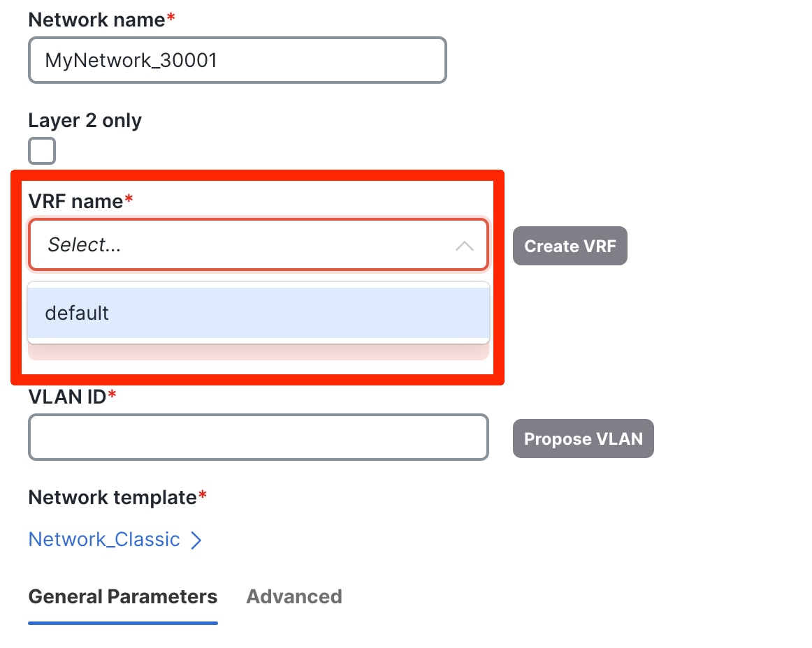
Layer 3 Network with a Custom VRF Instance
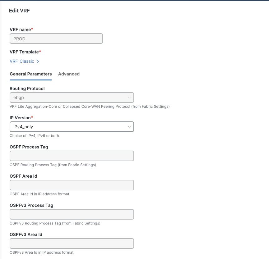
As with the Layer 3 Network in the Default VRF Instance scenario, you can create a Layer 3 network for a custom VRF instance instead of a default VRF instance. The only extra step includes creating a new VRF instance using the VRF_Classic template. ND picks the routing protocol for VRF_Lite from the fabric settings. There is also a flag to control per VRF instance iBGP/OSPF peering between Aggregations. You can enter the IP addresses for this when attaching the VRF instance, as discussed in the VRF-Lite Extension Between the Aggregation and Core/Edge Layers section.
Step 2: Create a VRF Instance to Link a Custom VRF Instance to This Layer 3 Network
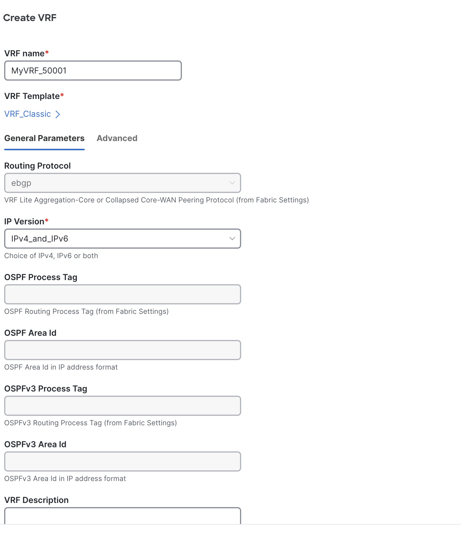
General Parameters include the Enable peering per VRF between Aggregations option. We recommend this option as a backup path to reach the Core switches should the link between the active FHRP to the Core go down.
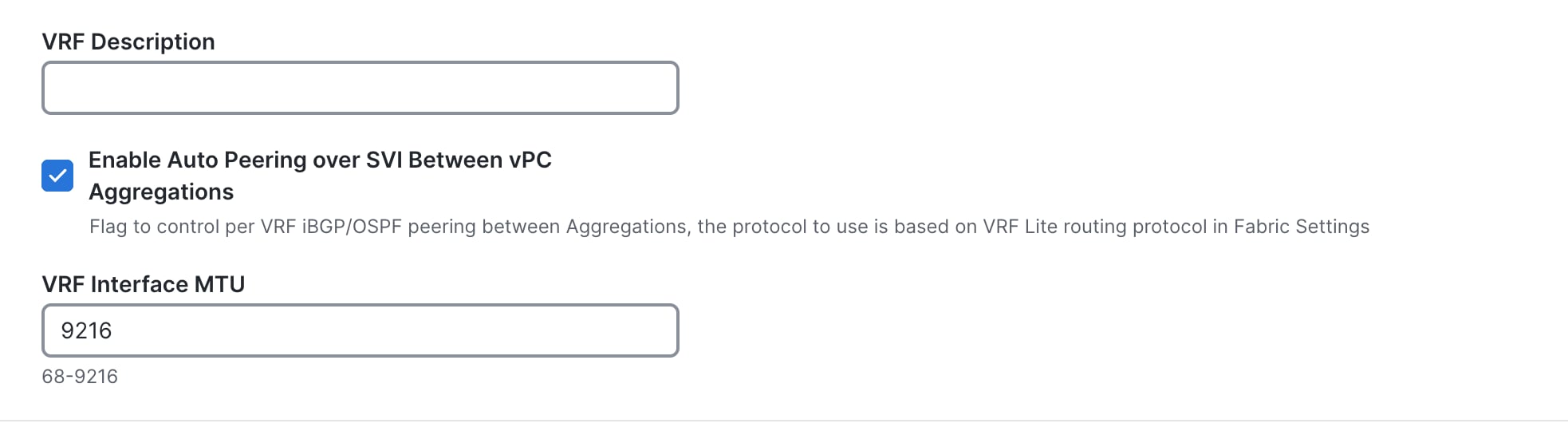
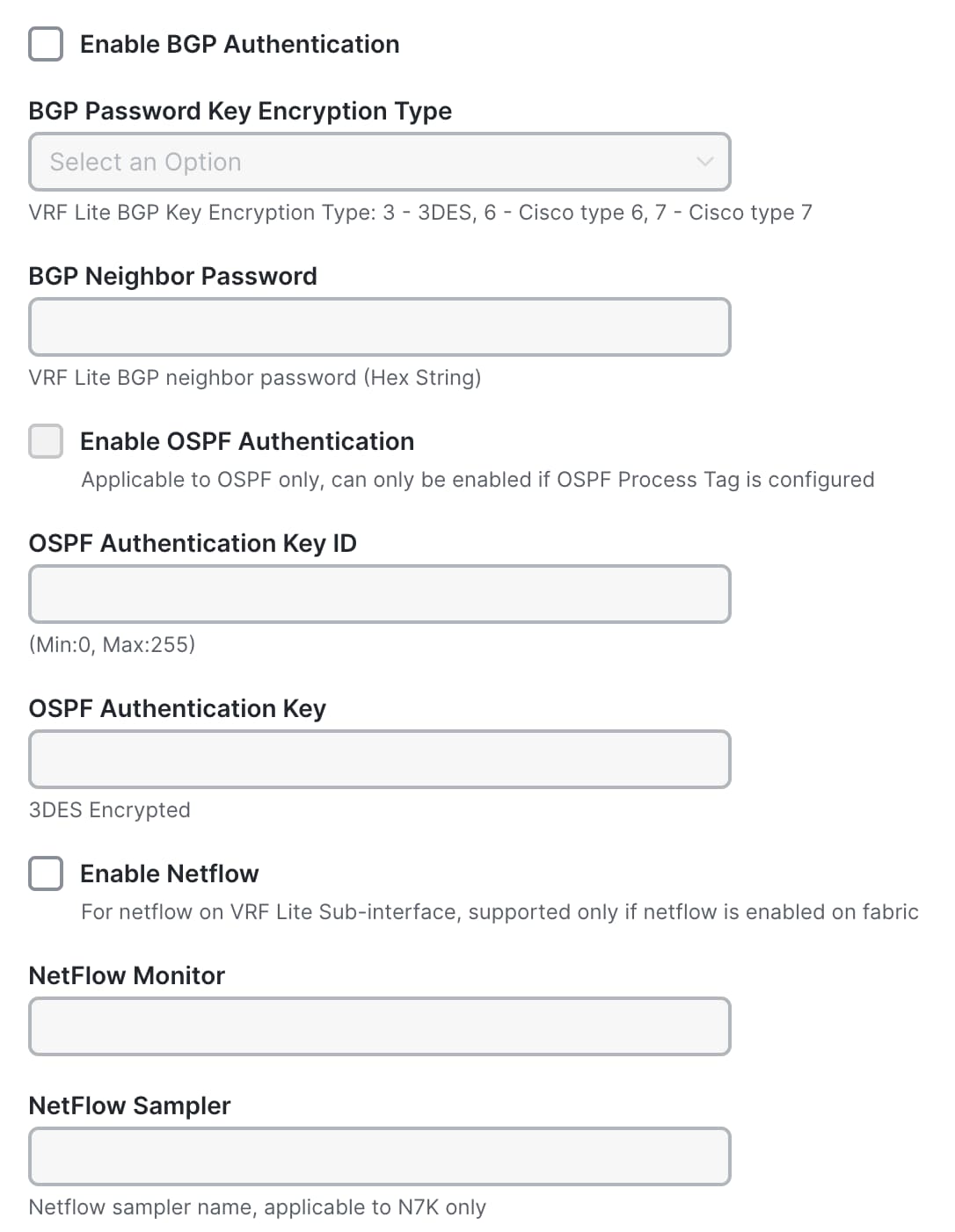
The Advanced tab includes options for BGP authentication, route maps, and static 0/0 configurations. That is, you can configure a default (0/0) route toward the Core layer.

Choose the FHRP active:
Step 4: Preview and Deploy the Configuration

The following screenshot shows access configurations to allow VLAN on host-facing ports and port channels between the Access and Aggregation layers:
Configuration at the Aggregation layer includes:
● Creating the VRF instance
● Creating an SVI for the VRF instance
● Instantiating a BGP session with route maps for the VRF instance that will be used for routing between the Aggregation and Core layers and between the Aggregation layers
● Creating an SVI for the gateway with relevant FHRP configurations
● Allowing the VLAN on port channel between the Access and Aggregation layers
Note: The route map is configured in the presence of SVI on Aggregations and for connectivity between Aggregations and Core. So, the Core has a reverse path to the Aggregation; the subnet needs to be advertised from the Aggregations to the Core. ‘Redistribute direct’ is done because the subnet configured is always with a direct route, and we want to control which subnets to advertise. The route map thus matches the tag (12345), which is editable.
ND also has a knob in the fabric settings under the Advanced tab that enables you to disable the default route maps, and you can optionally use user-provided route maps.

VRF-Lite Extension Between the Aggregation and Core/Edge Layers
ND supports Auto and Manual VRF-Lite between the Aggregation and Core/Edge layers. This document discusses Auto VRF-Lite configurations. ND supports the auto option with Cisco Nexus switches used for Core or Edge. The VRF Lite IP address version can be IPv4, IPv6, or IPv4 and IPv6.
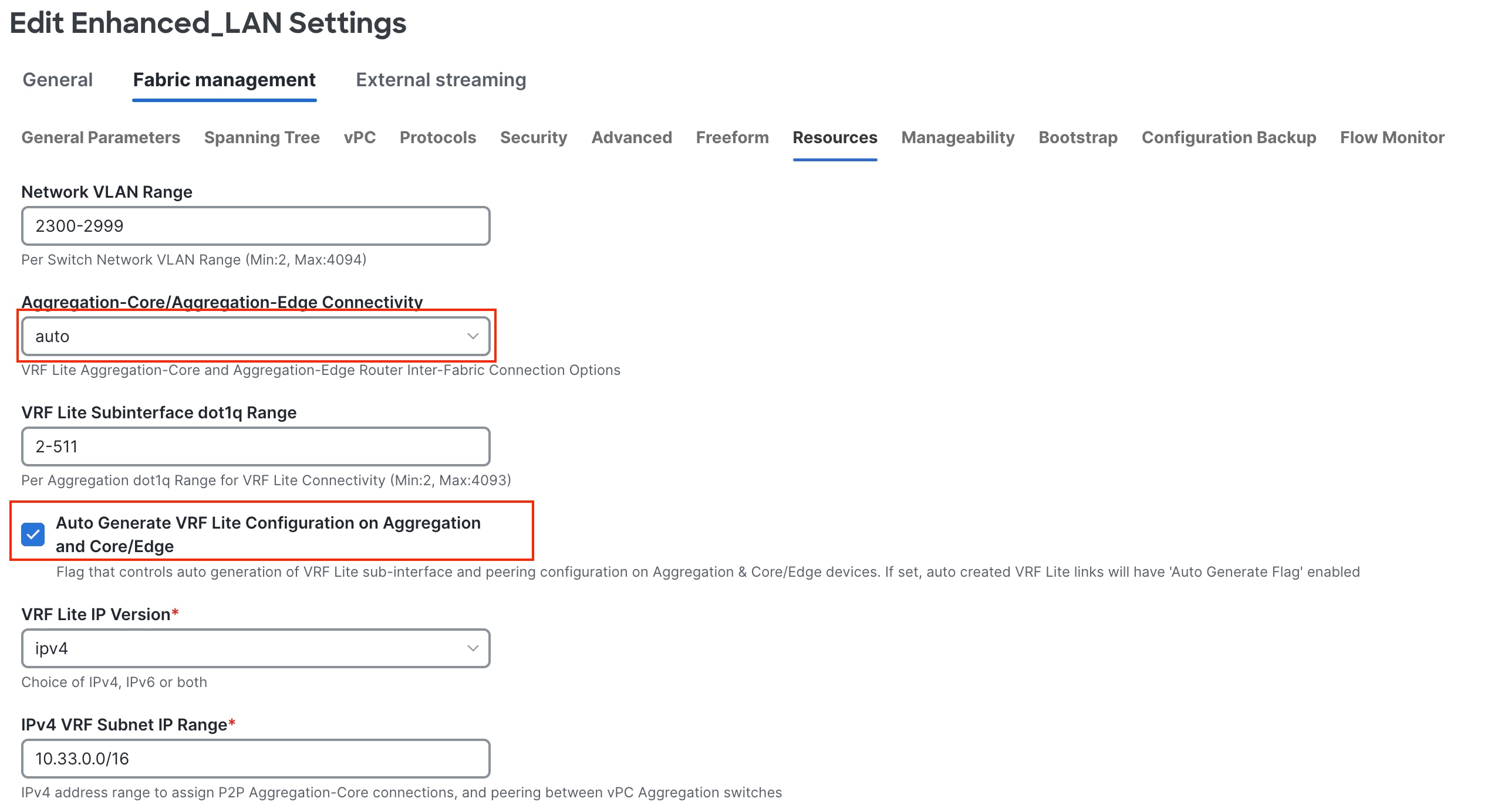
Under Resources in the fabric settings, set Agg-Core/Edge Connectivity to Auto and put a check in the Auto Generate VRF_Lite Configurations on Aggregation and Core/Edge check box. These are set by default, and you can disable them. However, if the Core/Edge are Cisco Nexus switches, we recommend that you keep the default option of auto-generating the configurations, as this option will generate all the configurations you must deploy without you having to define VRF_Lite configurations manually.
If you navigate to the fabric and check the links between the Aggregation and Core layers, the fabric must have the right template type attached to it with all parameters such as the source and destination Interfaces and BGP ASN all auto populated.
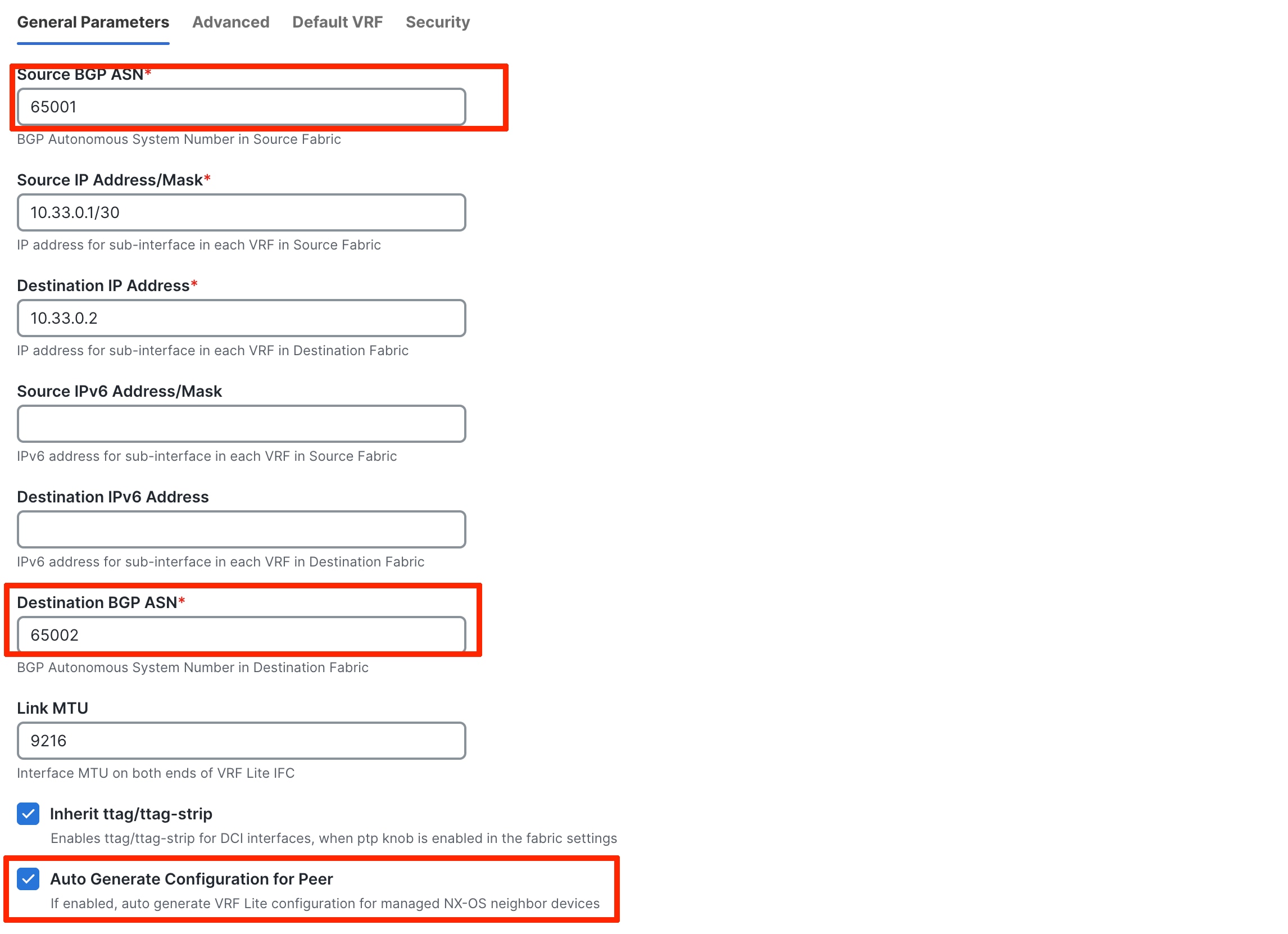
As seen in the General Parameters of the link, the Auto Generate Configuration for Peer box has a check, which will generate configurations for Core/Edge without you having to do so manually.
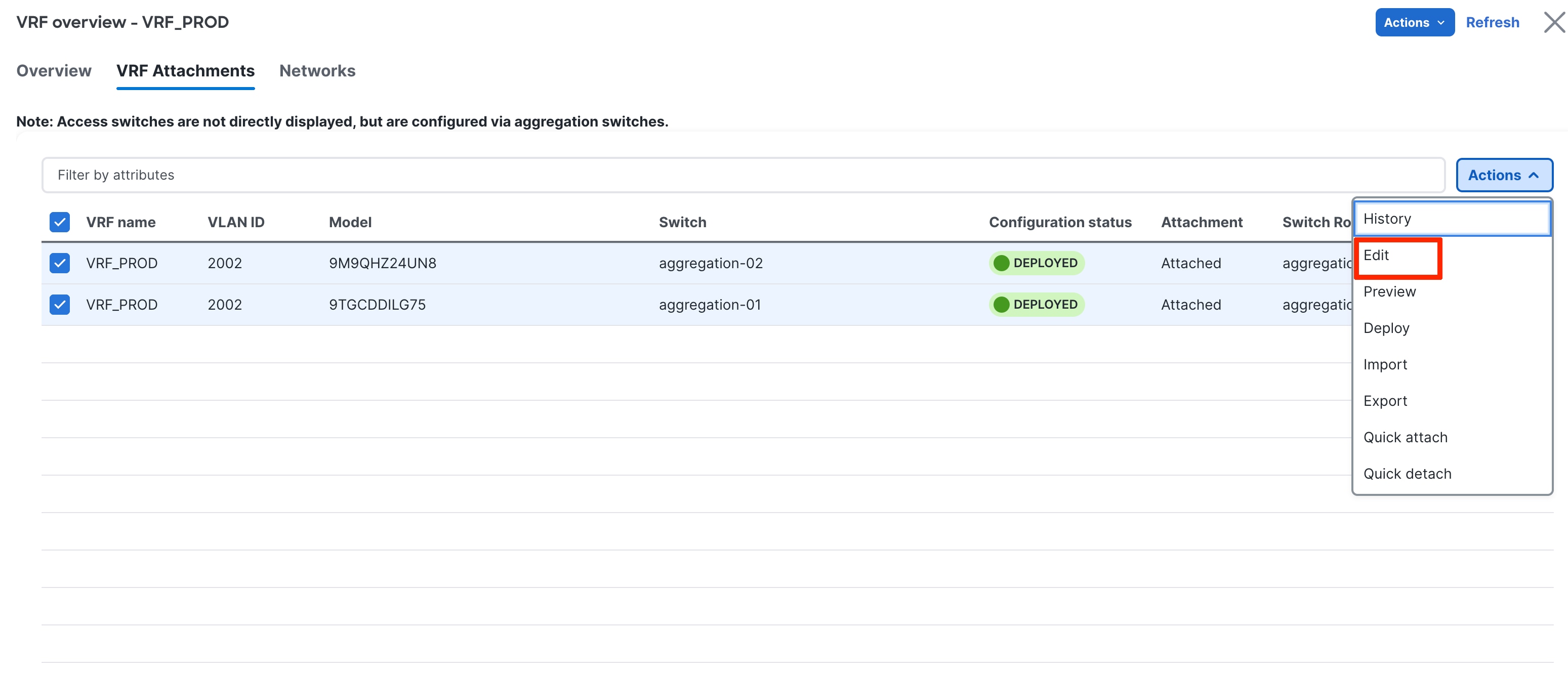
When you edit the VRF attachments of the VRF instance that you want to extend using VRF-Lite, ND shows a list of Aggregation to Core attachments that ND auto-detected with the respective VRF_Lite policy attached (for the auto generation of configurations) as shown in the following screenshot:
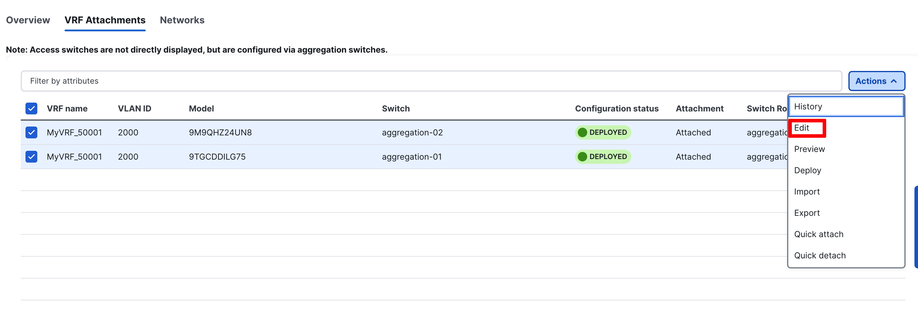
You can also see routing configurations between Aggregations on this screen.
Note: VRF instances have already been deployed on the Aggregation devices as a result of the network provisioning that you previously performed.
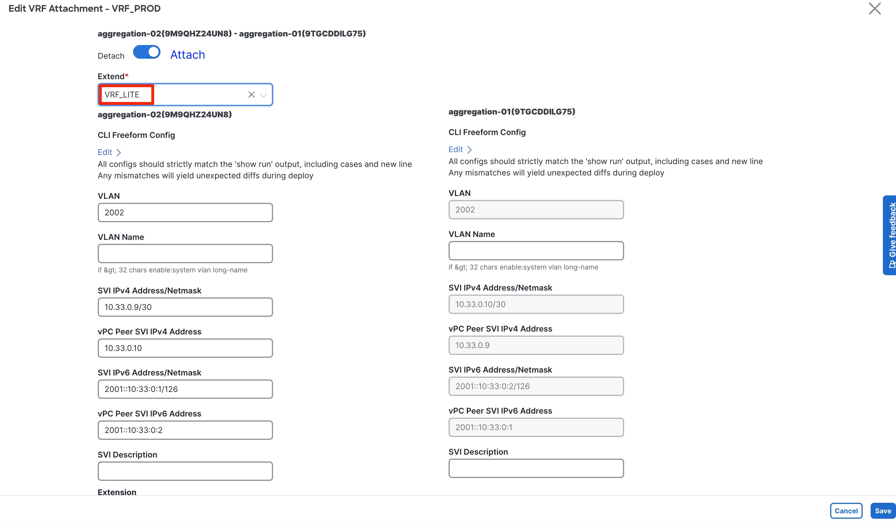
You should set the Extend option to VRF Lite.
ND automatically picks the IP addresses to be used for peering between Aggregations from the IP address pool, which is auto populated under Fabric Settings > Resources. You can customize this pool. This peering establishes routing between Aggregations to provide a backup route in case the links between FHRP Active (Aggregation) and Core go down.
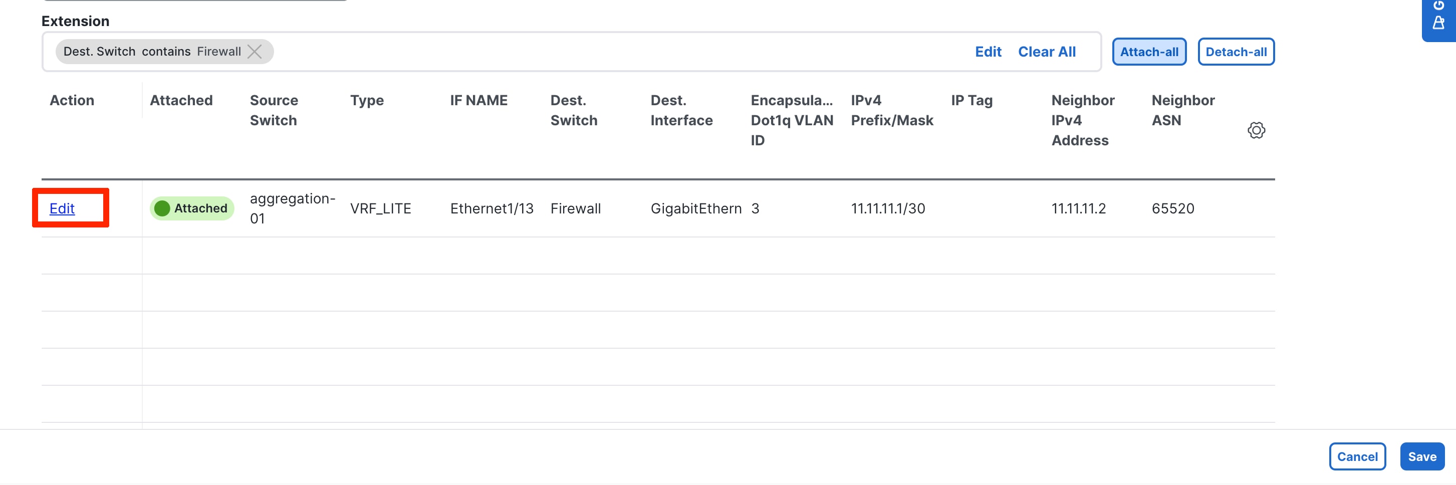
Next is establishing VRF_Lite between the Aggregation and Core/Edge layers. You can do Attach All or click Edit to select to extend specific connections.

After ND saves the intent to extend the VRF instance, you can perform a deploy operation first on the Aggregations in the Enhanced Classic LAN Fabric and then on the Core fabric for the Core.
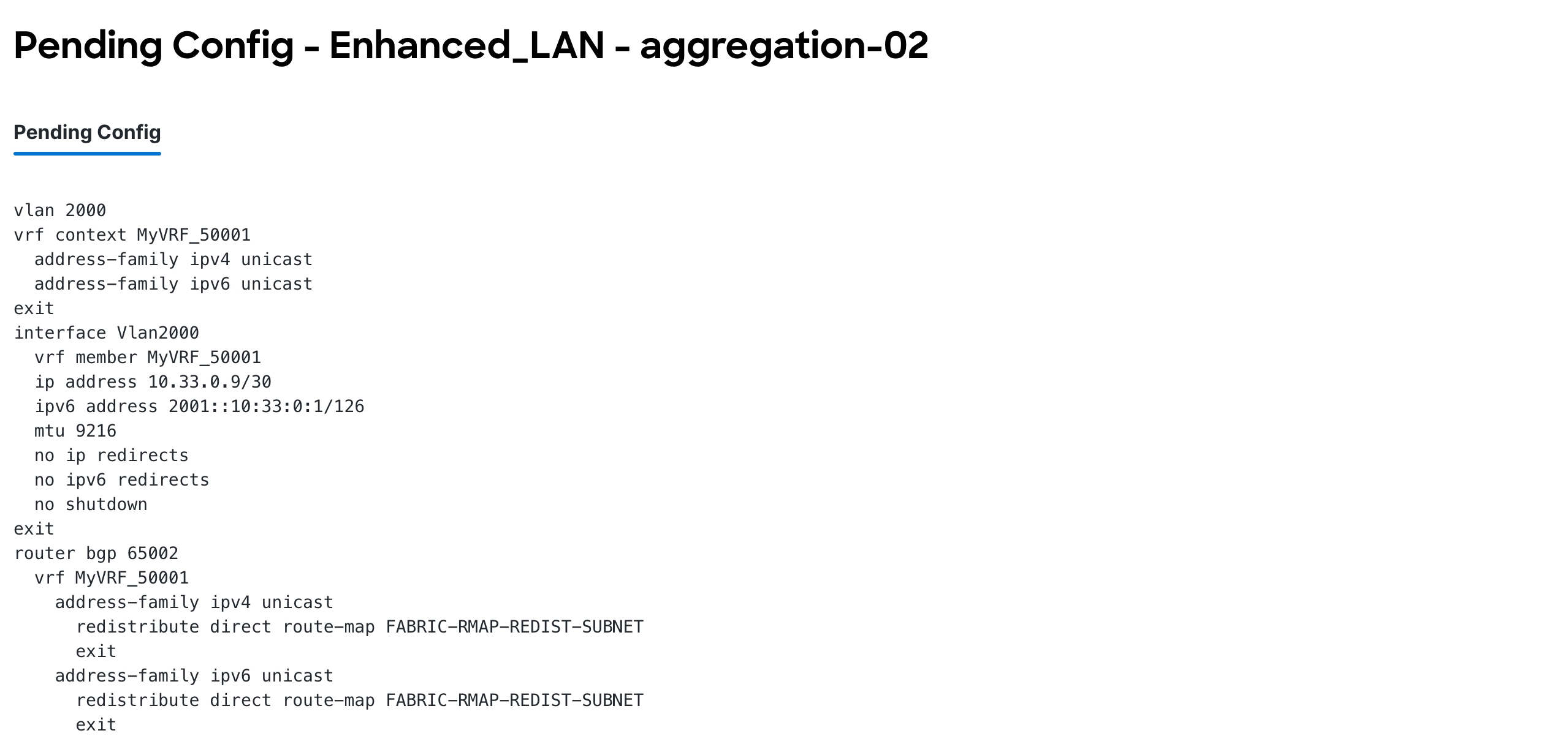
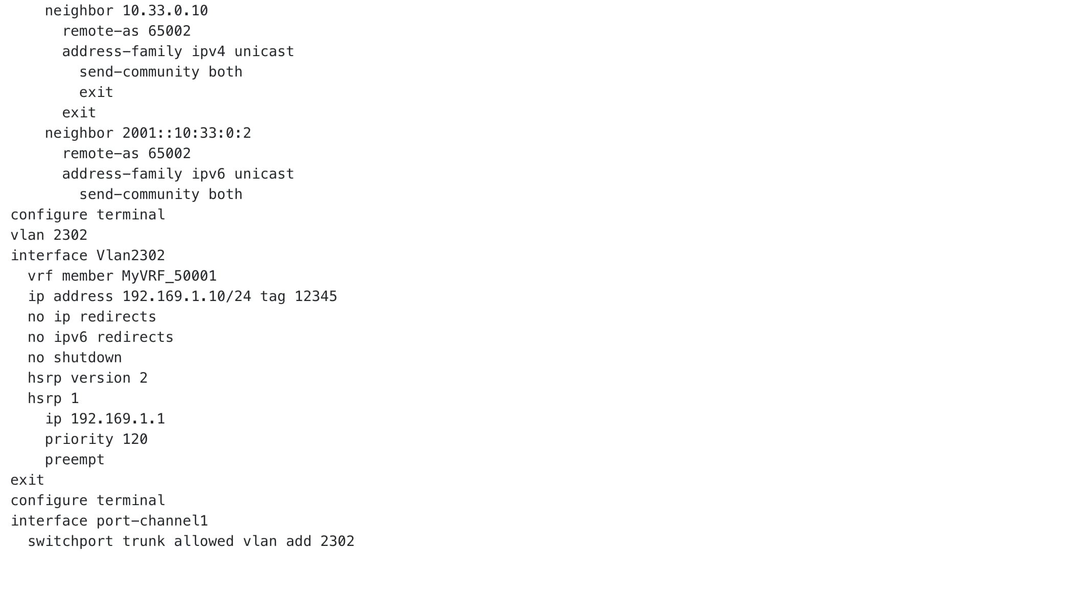
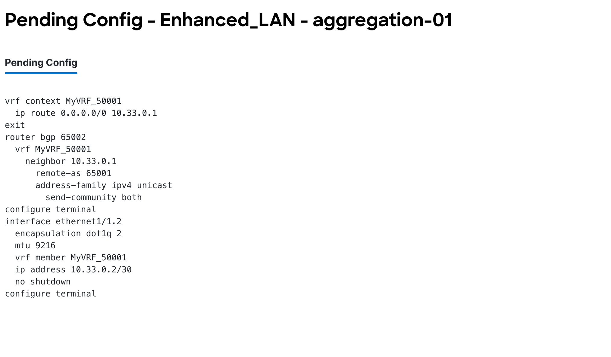
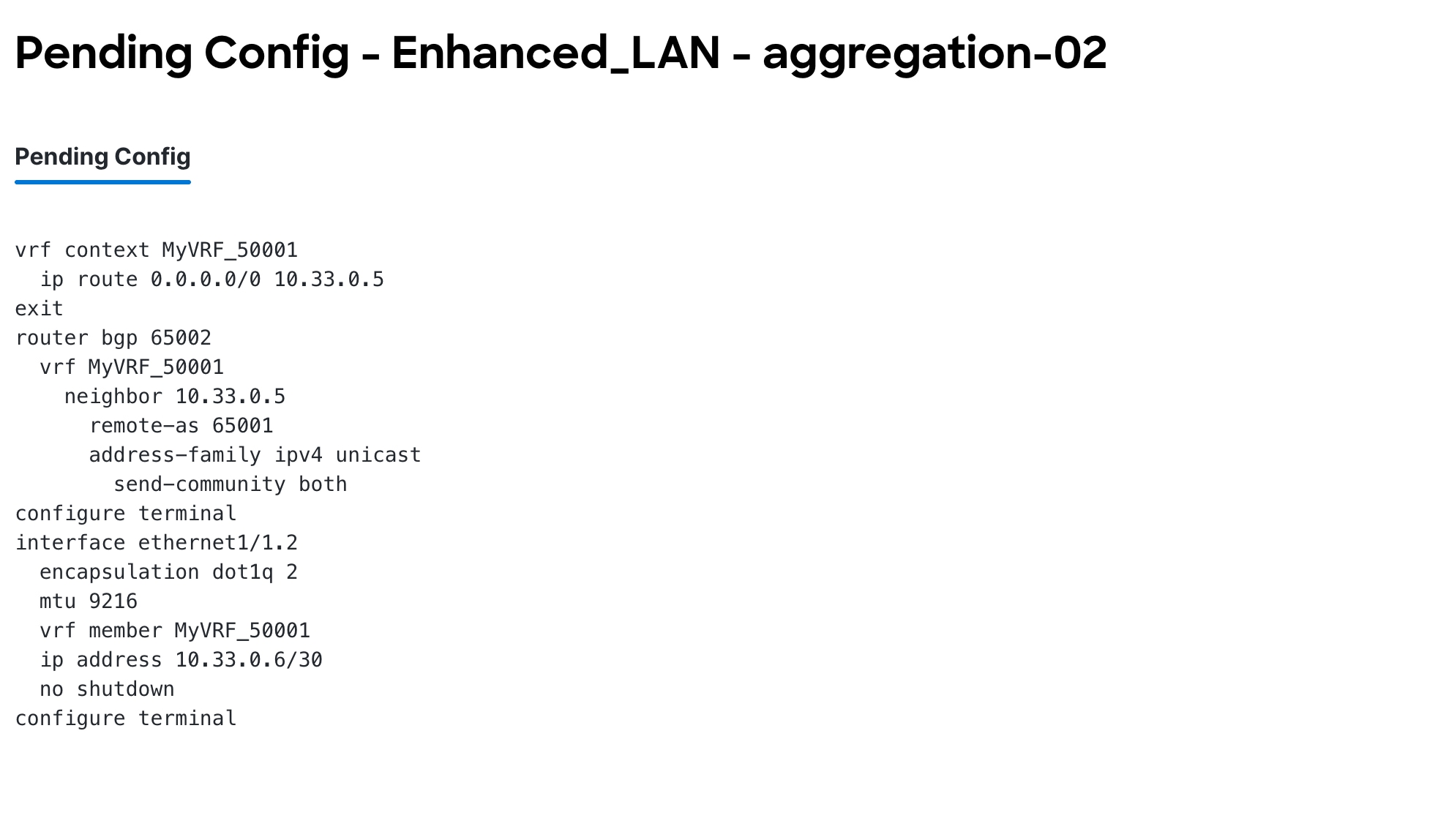
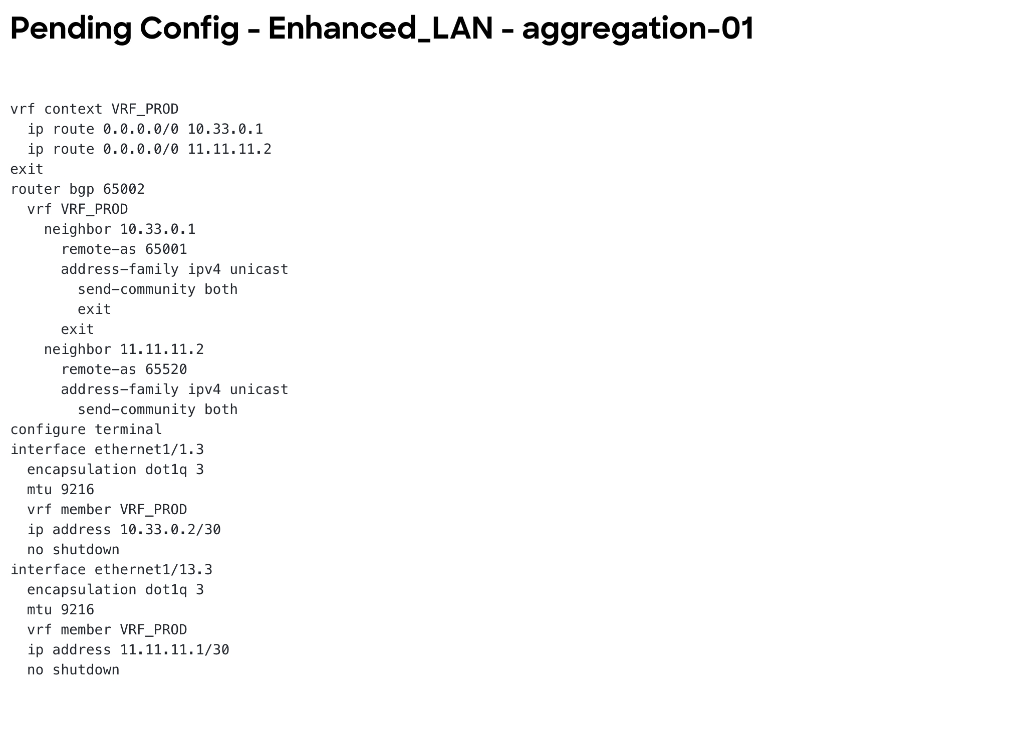
Step 3: Deploy on Aggregations
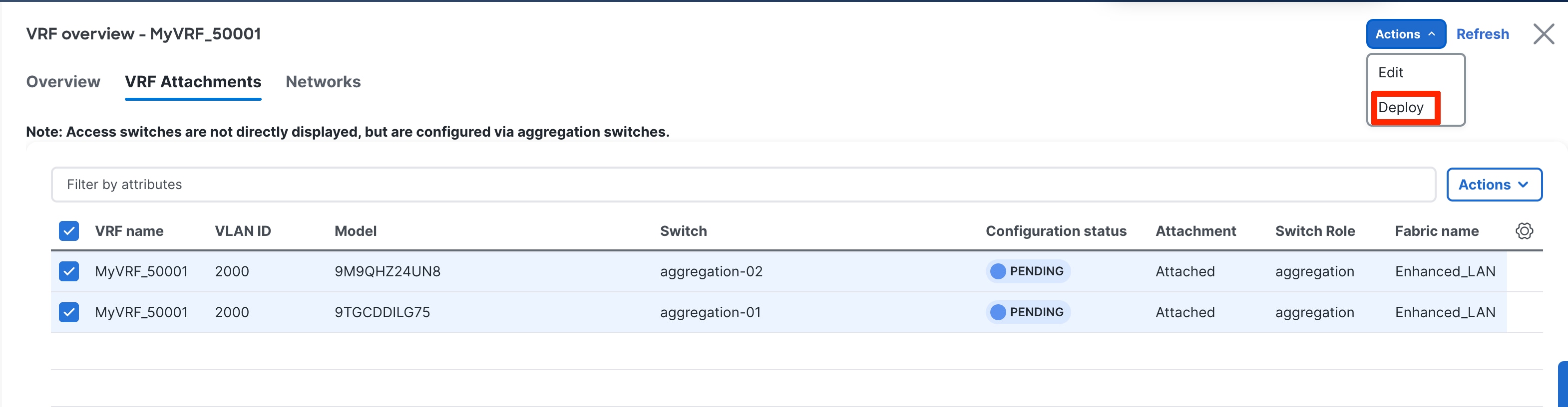
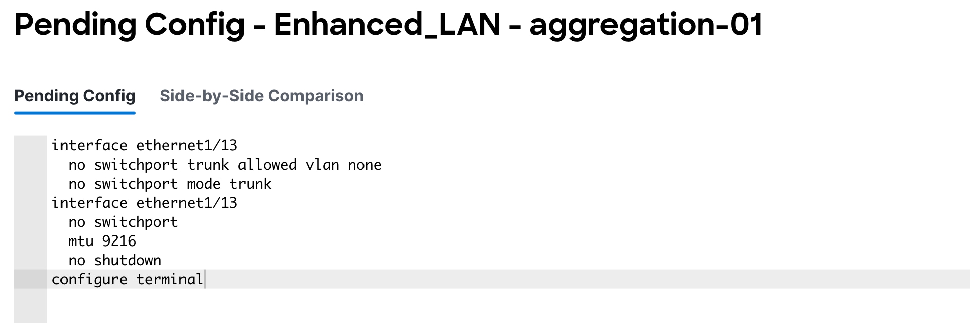
The Pending Configuration shows how ND creates sub-interfaces that are members of respective VRF instances, as well as the SVI for the VRF instance with the IP addresses entered during VRF instance extension (used for iBGP peering between Aggregations) and establishes peering between the Aggregation and Core layers for these sub-interfaces.
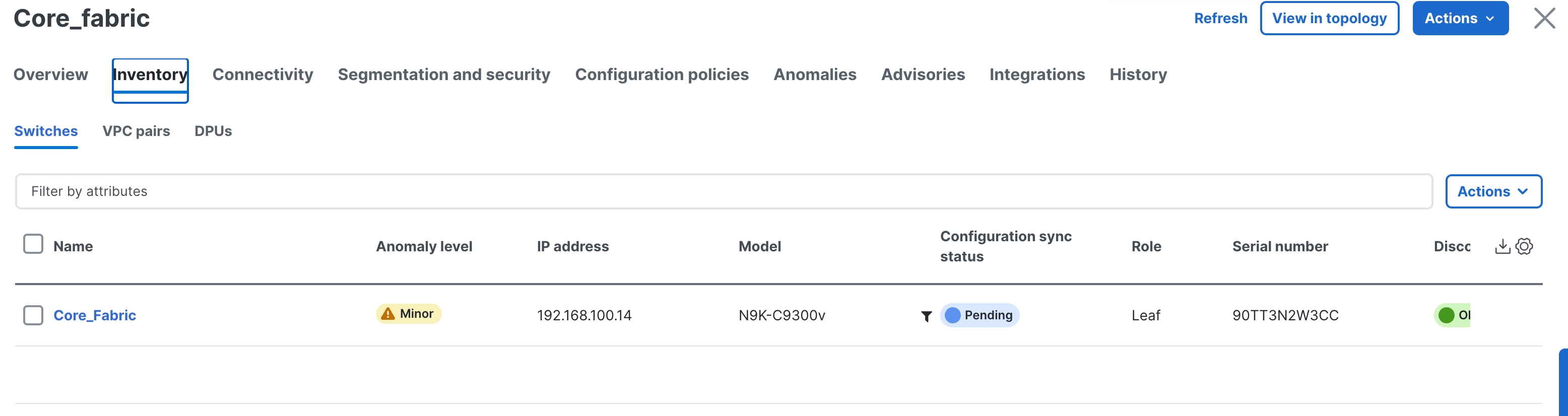
You must now perform the same deploy operation for the Core-Fabric to provision the pending configurations for the respective VRF-lite to the Core.

VRF-Lite extension between Collapsed Core and WAN
In case of Collapsed Core, you might need to use VRF-Lite between the Aggregation Role (Collapsed Core) and the WAN Router. The Aggregation switch will be a Cisco Nexus 9000. The WAN router can be managed in ND and can either be a Cisco Nexus or non-Cisco/non-Nexus device. The options are as follows:
● WAN router is a Cisco Nexus platform: When the WAN router is a Nexus device, the process remains the same as when we have a Core switch. The WAN router should be discovered and managed in the External and inter-fabric connectivity fabric with its role listed as "CORE." ND auto generates VRF-Lite configurations. All the steps for VRF-Lite between the Aggregation and the WAN router remain the same as the VRF-Lite Extension Between the Aggregation and Core/Edge LayersVRF-Lite Extension Between the Aggregation and Core/Edge Layers section.
● WAN router is a non-Nexus (Cisco) platform: When the WAN router is a non-Nexus device, the router should still be discovered and managed in the External and inter-fabric connectivity fabric with the role of "CORE." If the Auto Generate Configuration for Peer field is enabled, and the edge device is an IOS XR device, enter ios_xr_Ext_VRF_Lite_Jython in the Template for Configuration Generation on Peer field. If Auto Generate Configuration for Peer is enabled, and the edge device is an IOS XE device, enter ios_xe_Ext_VRF_Lite_Jython in the Template for Configuration Generation on Peer field.
● WAN router is a non-Nexus (Non-Cisco) platform: When the WAN router is a non-Nexus device, the router should still be discovered and managed in the External and inter-fabric connectivity fabric with the role of "CORE." However, the VRF-Lite configurations will not be auto-generated. You must add the VRF-Lite Jython policy on the WAN router manually.
See the following procedures in the Working with Connectivity in Your Nexus Dashboard LAN FabricsWorking with Connectivity in Your Nexus Dashboard LAN Fabrics
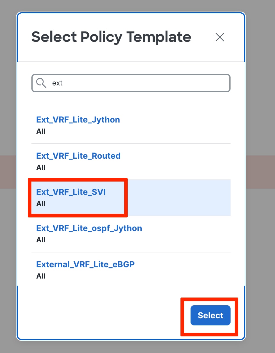
● VRF-Lite to WAN router using a routed interface or port channel: Whether the WAN router is a Nexus or non-Nexus device, there may be scenarios where you want to use VRF-Lite using SVIs or Routed Port/Port-Channels. ND VRF-lite auto-workflow supports VRF-Lite extension only for sub-interfaces. Users can deploy policies manually when VRF-Lite between the Collapsed Core and WAN is required using routed interfaces or SVIs.
The policies are as follows:
◦ Ext_VRF_Lite_SVI (for VRF-Lite using an SVI)
◦ Ext_VRF_Lite_Routed (for VRF-Lite using routed ports or port channels)
Day 2 for Enhanced Classic LAN
All maintenance and operational features listed below are supported equally for Classic LAN networks and VXLAN fabrics:
● Image Management: upgrades, downgrades, EPLDs, RPMs, and SMUs
● Change Management and Rollback
● Inventory View
● Event Analytics
● Deployment History and Audit Logs
● Backup and Restore
● Performance Metrics, Link and Interface stats, and Protocol Views
● Programmable Reports
● Virtual infrastructure (VMM, K8s, OpenStack) Visibility
These features are agnostic to the fabric type. For more information about these features, see the Cisco ND Configuration Guide.
Note:
● To use alarms and get immediate notification of link/interfaces/switch down, you must configure ND as a trap destination.
● For syslog, ND by default is not a syslog receiver. You must configure ND to be a syslog receiver, and thereafter you can define policies to capture syslog messages of interest and trigger the appropriate alarms. Performance monitoring does not require this, as performance monitoring is an SNMPv3 poll from ND to the switch.
● SCP is required for image management, NX-API certificate installation, NDI functionality, and POAP.
● SNMP is used for device discovery.
● Both SCP and SNMP pods are always enabled by default. Please refer to the Nexus Dashboard persistent IP addressesNexus Dashboard persistent IP addresses to understand the persistent IP requirements in 4.1.1
Integration of Classic LAN with Services
It is common for services such as firewalls and load balancers to be connected to Aggregations or Collapsed Core (a switch serving as Layer 2/Layer 3 boundary), with traffic being redirected to these services for security or traffic optimizations.
In scenarios with services such as a firewall attached to an Enhanced Classic LAN fabric, you must manually provision the respective configurations to the service devices. ND will not push any configurations to these.
You can achieve connectivity to the service device using the following options:
● VRF-Lite Using SubinterfacesVRF-Lite Using Subinterfaces
● VRF-Lite Using SVIsVRF-Lite Using SVIs
● VRF-Lite Using Routed Interfaces or Port ChannelsVRF-Lite Using Routed Interfaces or Port Channels
Note: The most common option is to use VRF-Lite with SVIs, as service nodes are typically deployed as a cluster (active/active or active/standby), and the cluster requires Layer 2 adjacency. You can use the sub-interfaces and routed interface or port channels option in the case of a standalone service node (that is, you do not have a cluster).
The succeeding subsections discuss these workflows. For the configurations, assume the Aggregation switch is connected to the firewall.
You must create a separate fabric using the "External and inter-fabric connectivity" fabric type for the service device.
The firewalls that connect to Enhanced Classic LAN fabric type do not support the existing Layer 4 to Layer 7 services workflow in ND as of release 4.1.1 Hence, these firewalls will be added as a meta device. From a routing or VRF-lite perspective, devices are considered to be unmanaged.
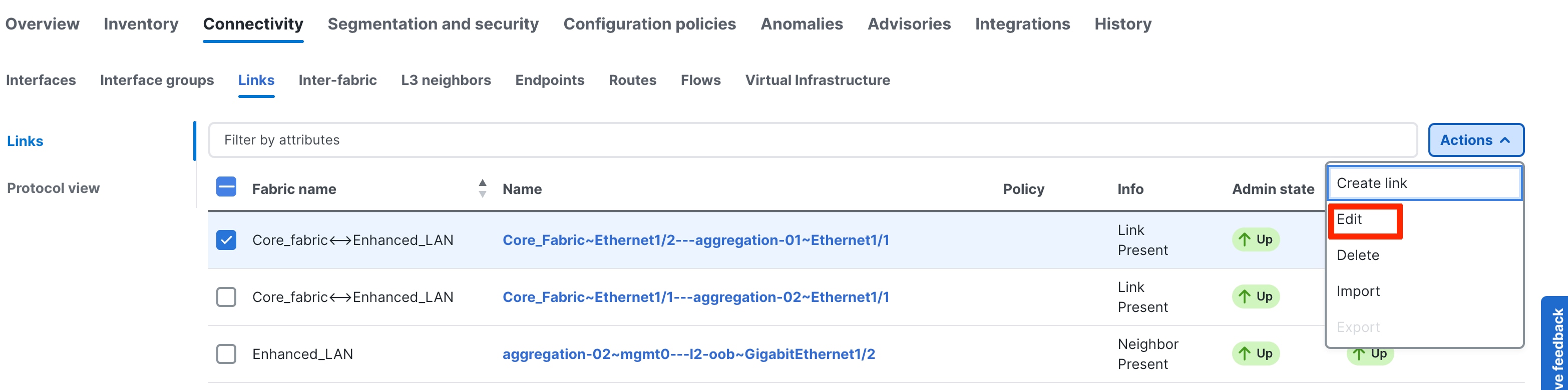
You must browse the Links under the Enhanced Classic LAN fabric and choose Actions > Create.
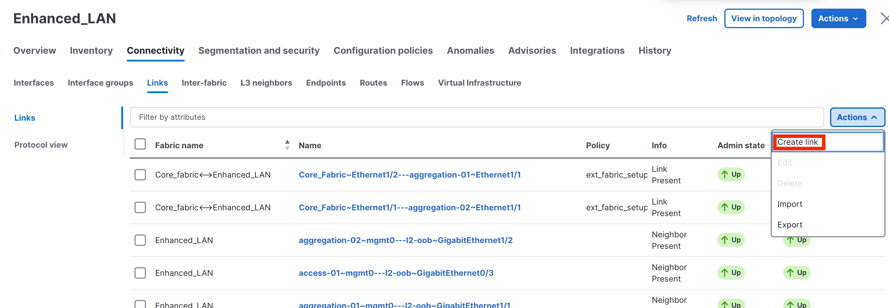
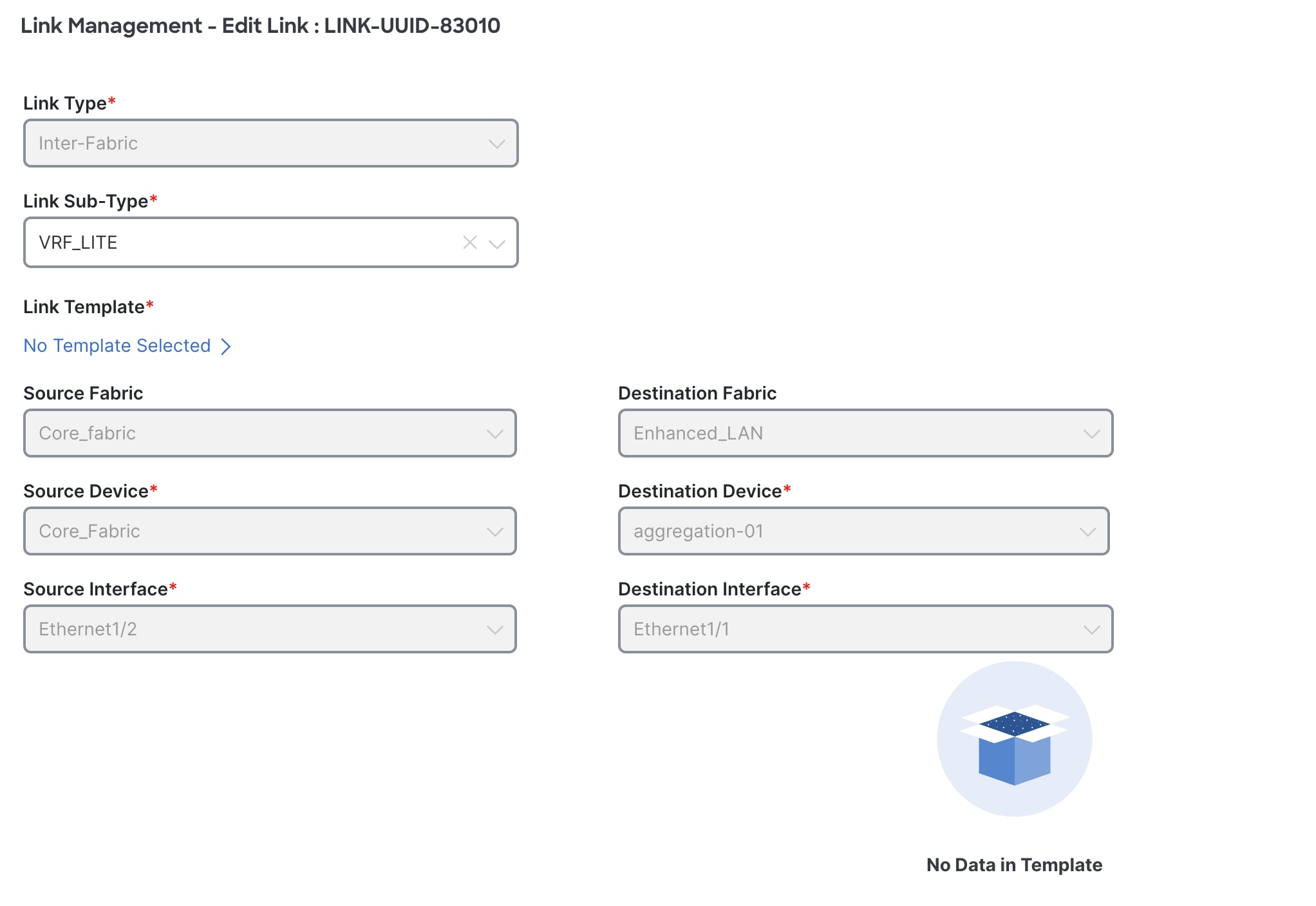
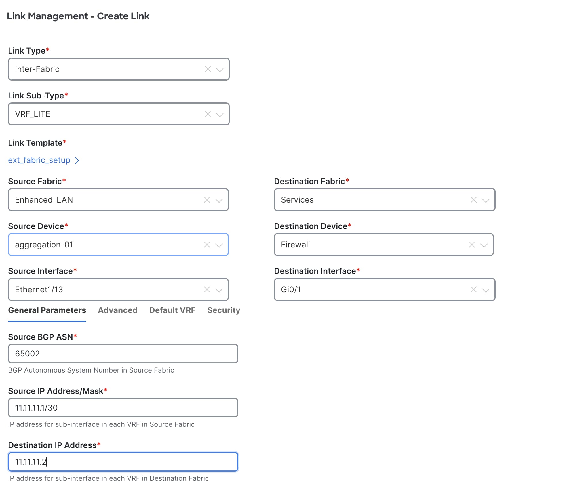
In the Link Management – Create Link dialog, perform the following procedure:
1. For Link Type, choose Inter-fabric.
2. For Link Sub-Type, choose VRF-Lite.
3. For Source Fabric, choose the Enhanced Classic LAN fabric that you created.
4. For Destination Fabric, choose Services.
5. For Source Device, choose the switch that the firewall is attached to, such as the Aggregation switch.
6. For Destination Device, choose the name of the firewall.
7. For Source Interface, choose the interface, such as "Ethernet1/27" on the Aggregation switch.
8. For Destination Interface, choose an interface.
9. For Source BGP ASN, enter the BGP autonomous system number that is in the source fabric.
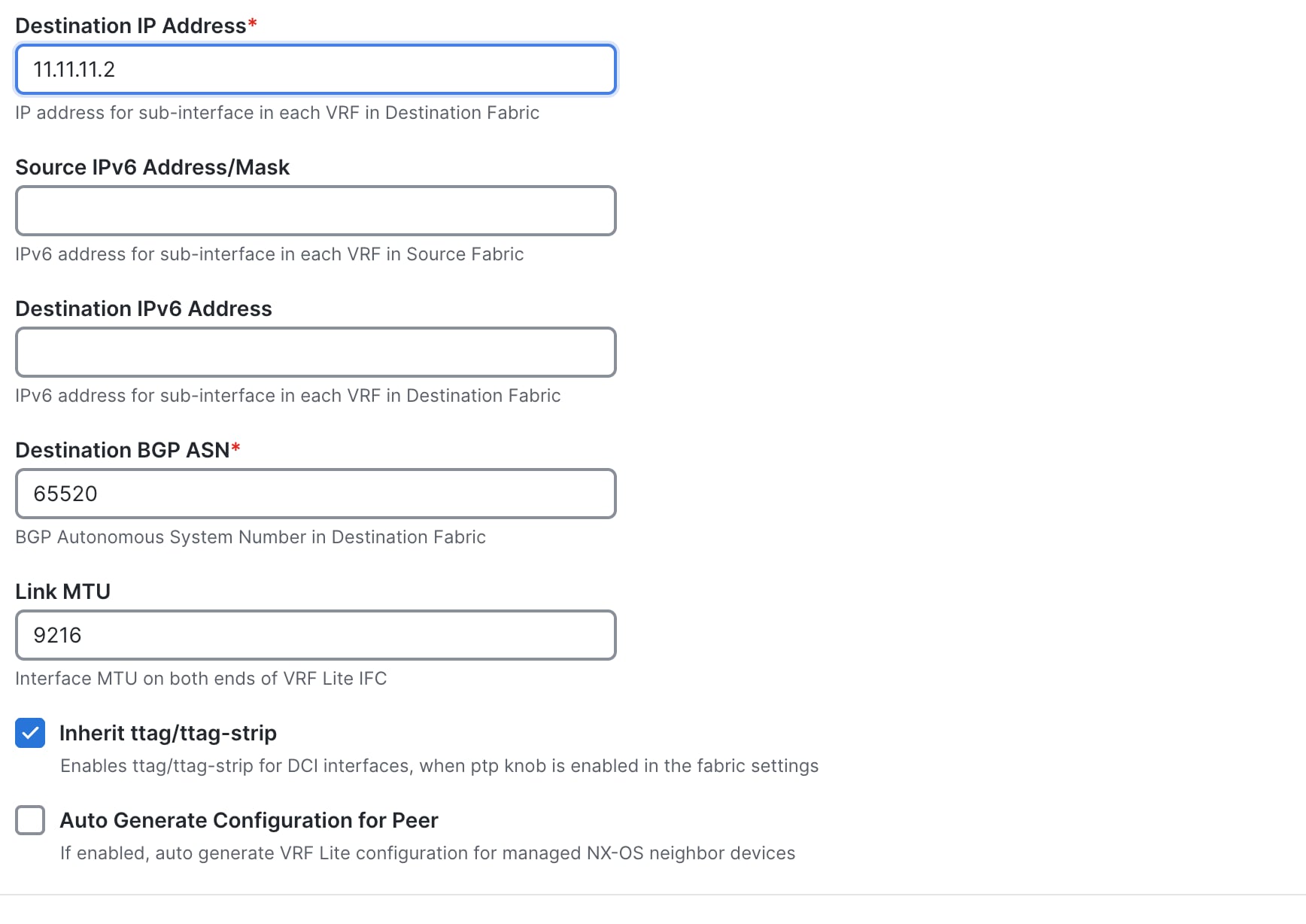
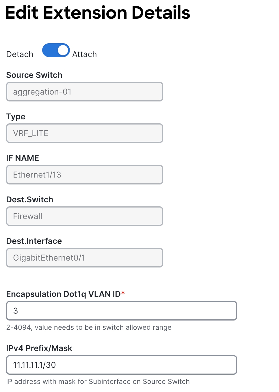
10. For Source IP Address/Mask, enter the IP address and mask for the Ethernet1/27 sub-interface, which is the source interface of the inter-fabric connection (IFC). ND creates a sub-interface for each VRF instance that is extended over this IFC and assigns a unique 802.1Q ID to the sub-interface. ND uses the IP address/mask that you enter, along with the value of the BGP Neighbor IP field, as the default values for the sub-interface that ND creates at the VRF extension. You can overwrite the default values.
11. For Destination IPv6 Address, enter the BGP neighbor IP address on the meta-device.
12. Click Save.
For more information, see the Working with Connectivity in Your Nexus Dashboard LAN Fabrics.
After saving, ND creates the following link between the two fabrics, with the firewall as a meta device:
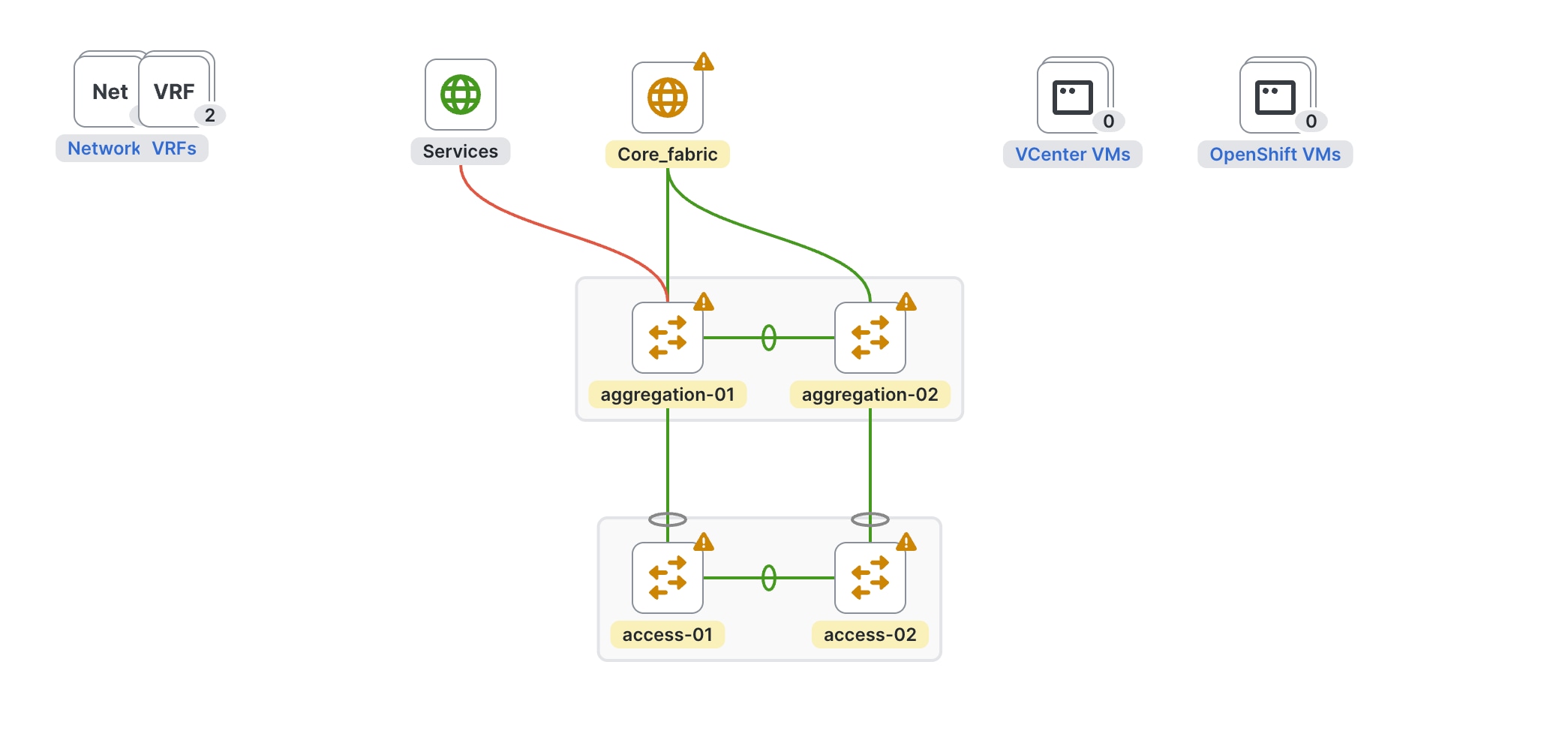
Make sure to deploy the pending configurations on the Aggregation switch, which marks the source interface defined as a routed port.

The VRF-Lite workflow is identical to VRF-Lite between Aggregation and Core, as described in the Day1 for Classic LAN section.
The following screenshots summarize the process of configuring the VRF-Lite extension on a VRF instance that you created:
For the procedure to create a new VRF instance, see the Layer 3 Network with a Custom VRF Instance section.
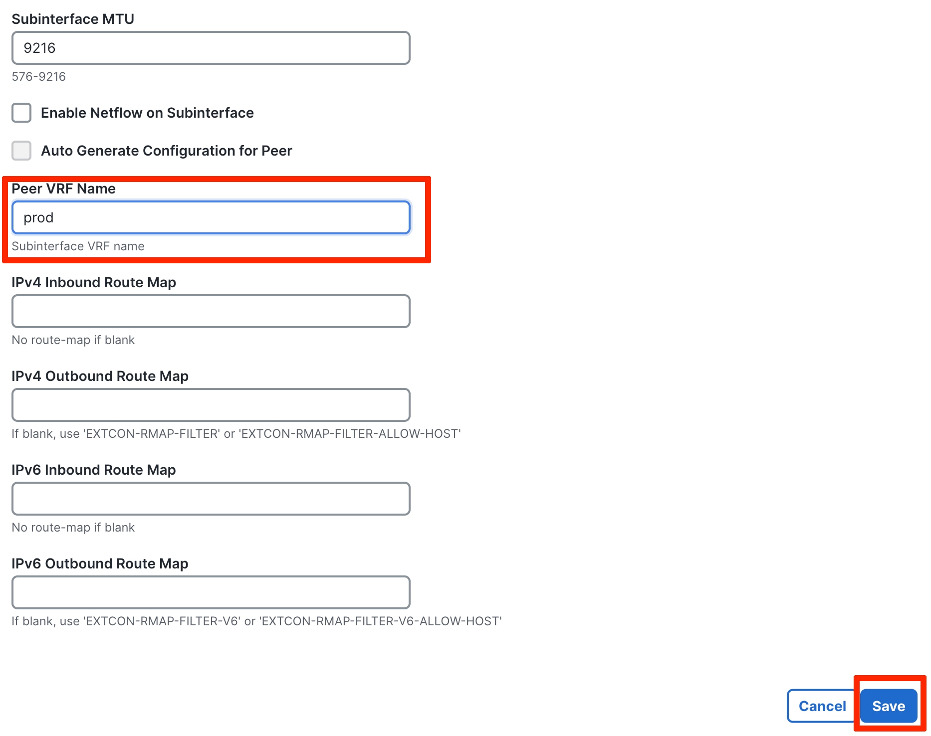
You can enter the peer VRF instance by editing the extension. The IP addresses shown in the screenshot are what you entered when you created the links, and you can overwrite the IP addresses at this point. Click Save to save the extension.
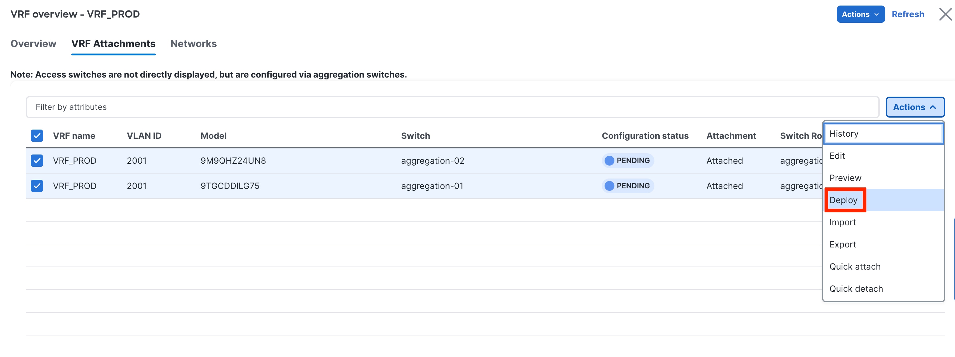
Choose Actions > Deploy the VRF instance.
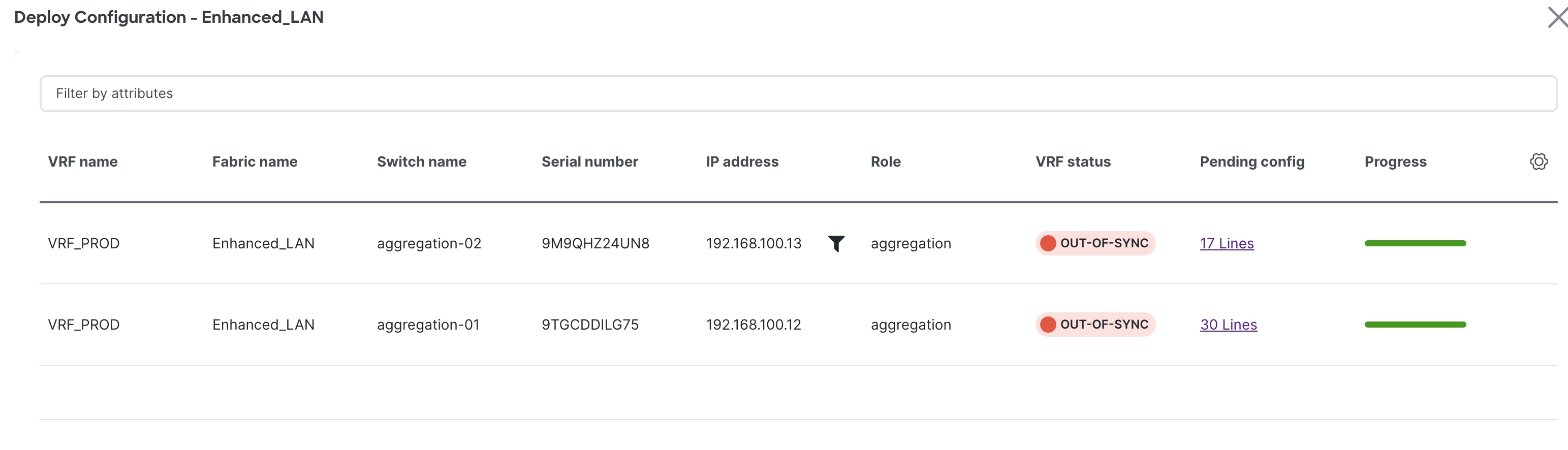
The following configuration is generated for the Aggregation switch. You must provision the firewall/service device with equivalent configurations for the peering to be up.
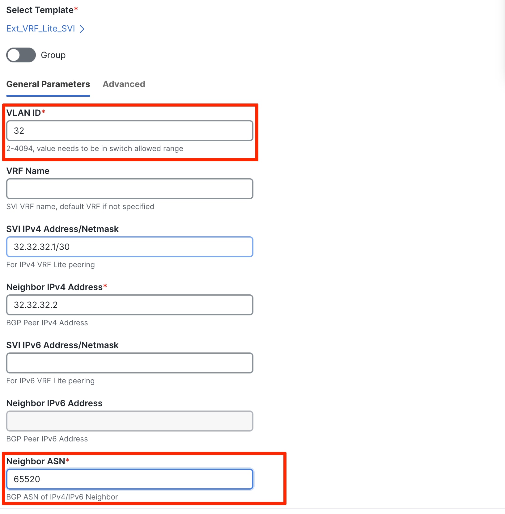
In cases where firewalls do not support subi-nterfaces, you can use SVIs for VRF-Lite with eBGP. You must do this on the Aggregation layer using the Ext_VRF_lite_SVI policy that is included with ND.
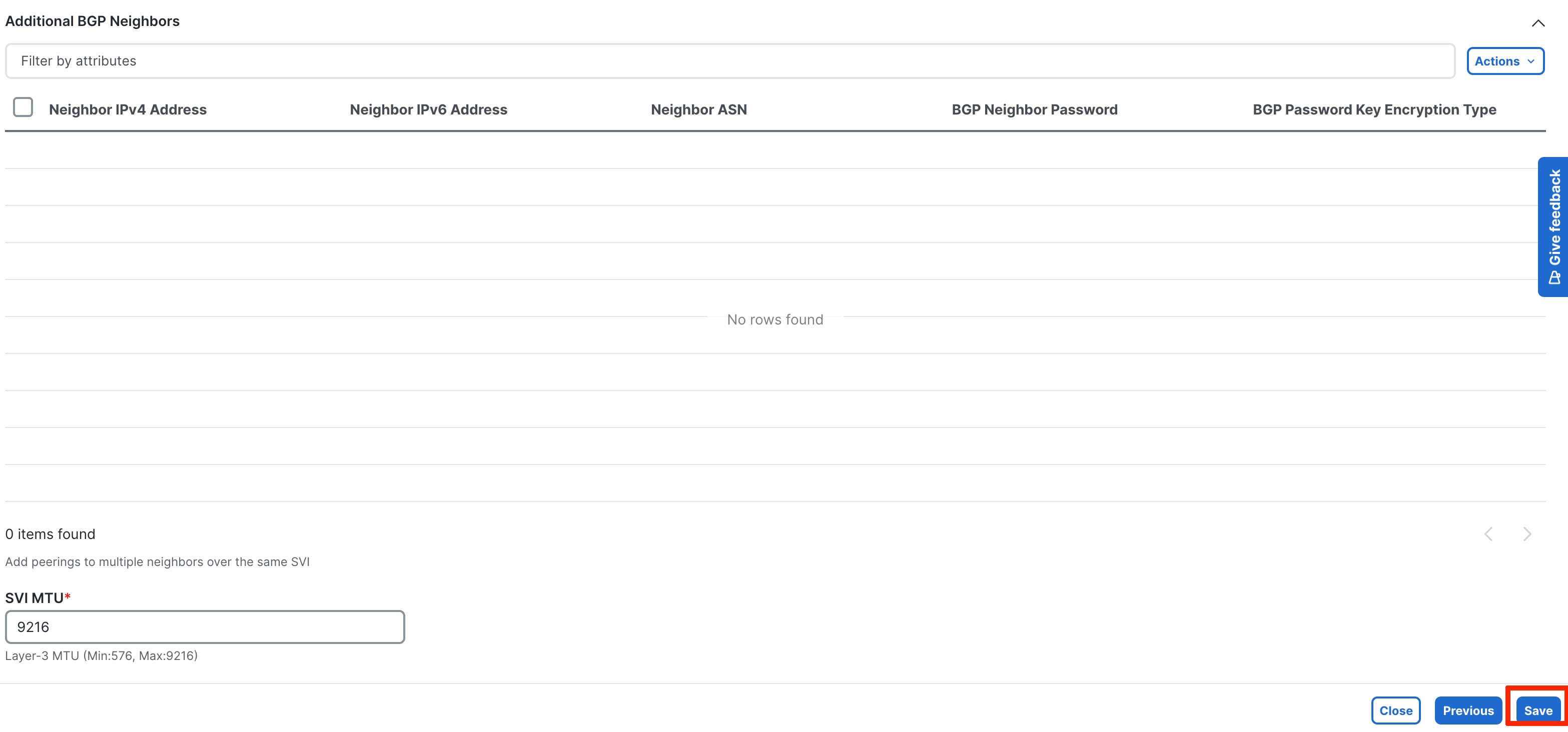
The following screenshots summarize the process:
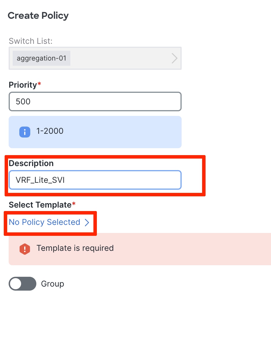
Input the parameters in the Ext_VRF_lite_SVI policy:
To see the generated configuration, choose the policy, the Actions -> Generated Config. You can now push the policy to the Aggregation switch.
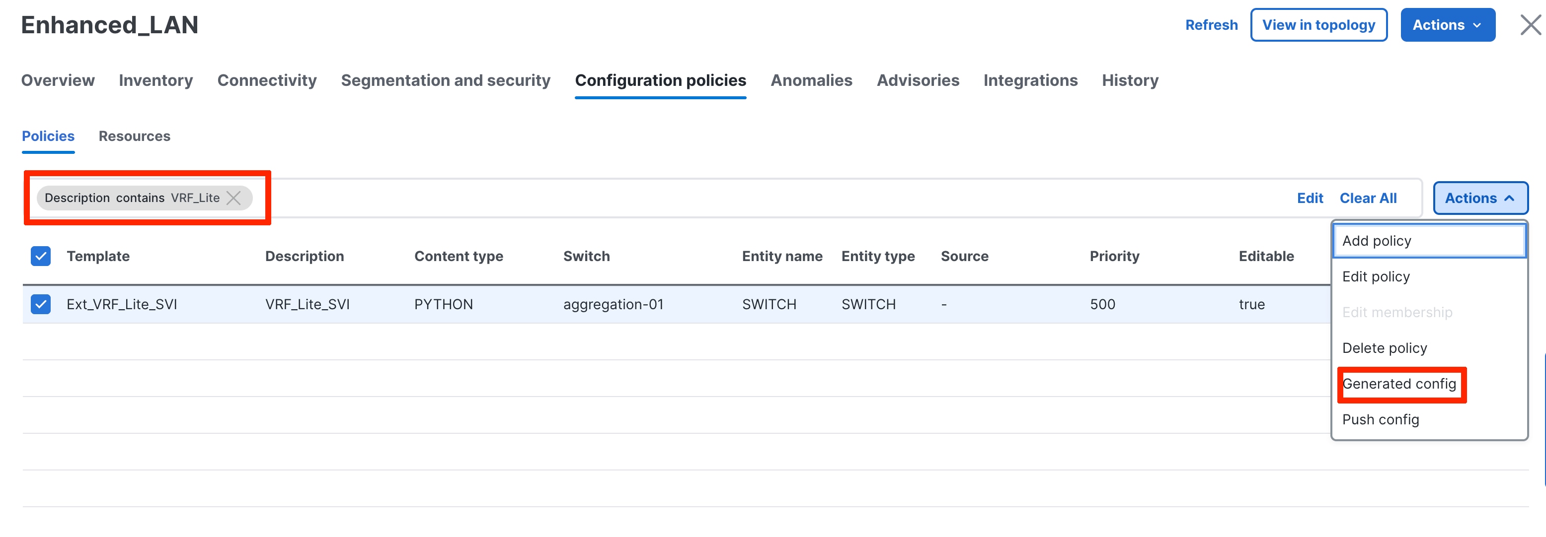
The following screenshot shows the generated configuration for an SVI-based VRF-Lite:
You must also provision the appropriate configurations on the firewall for the peering to come up.
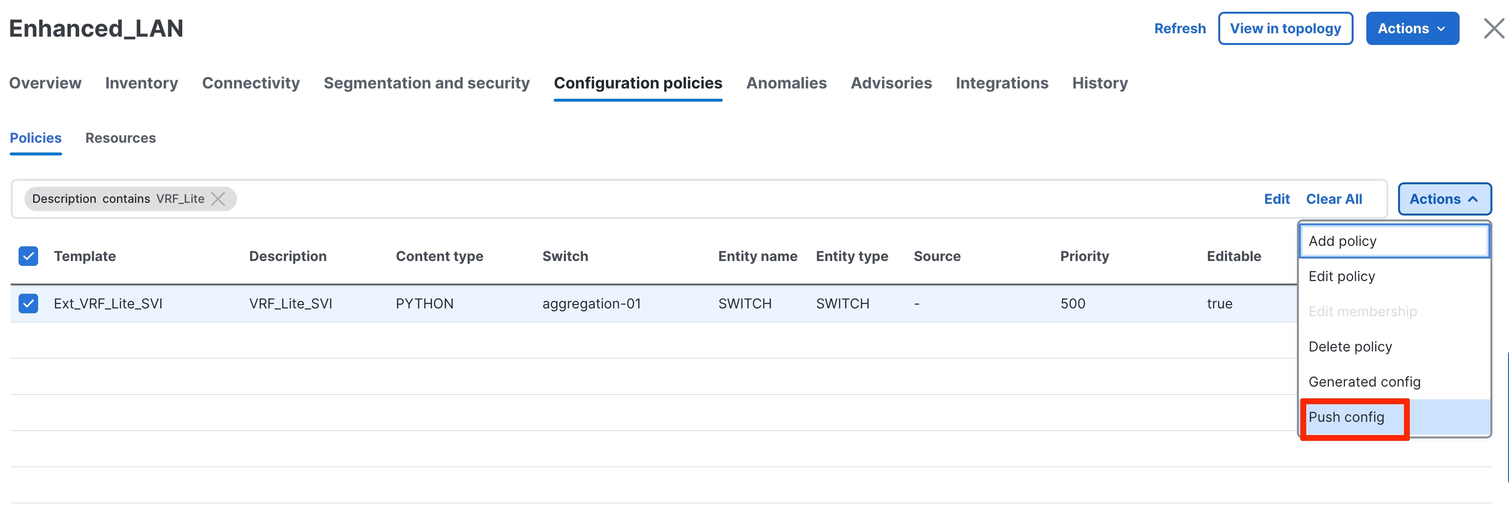
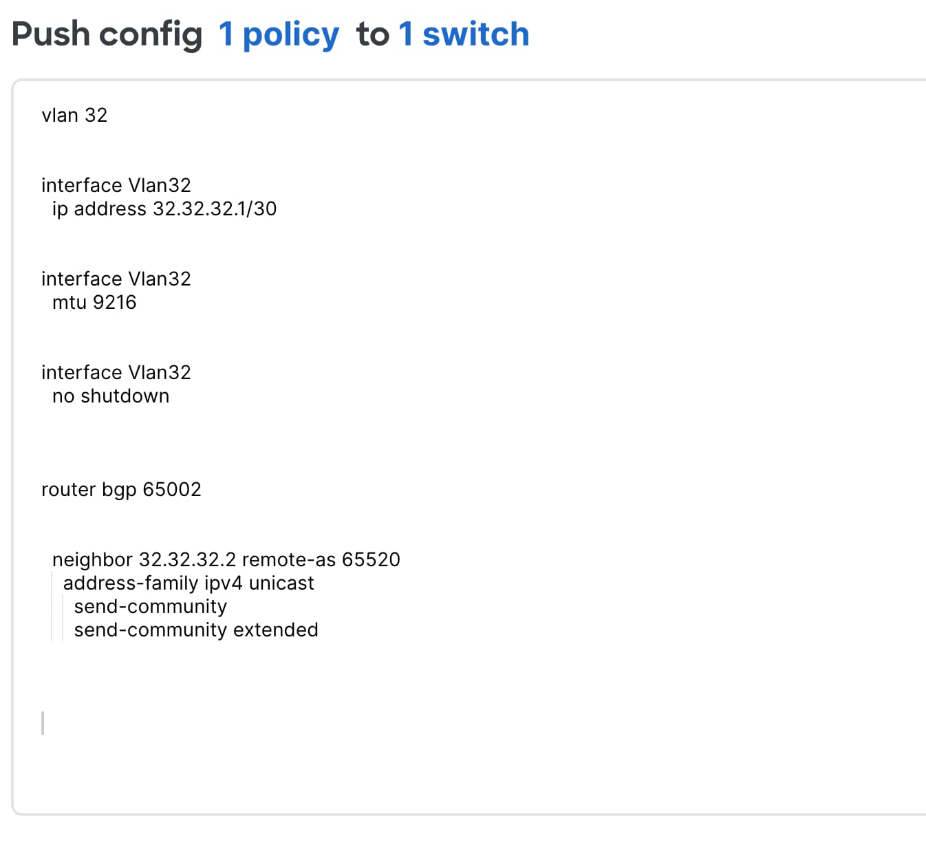
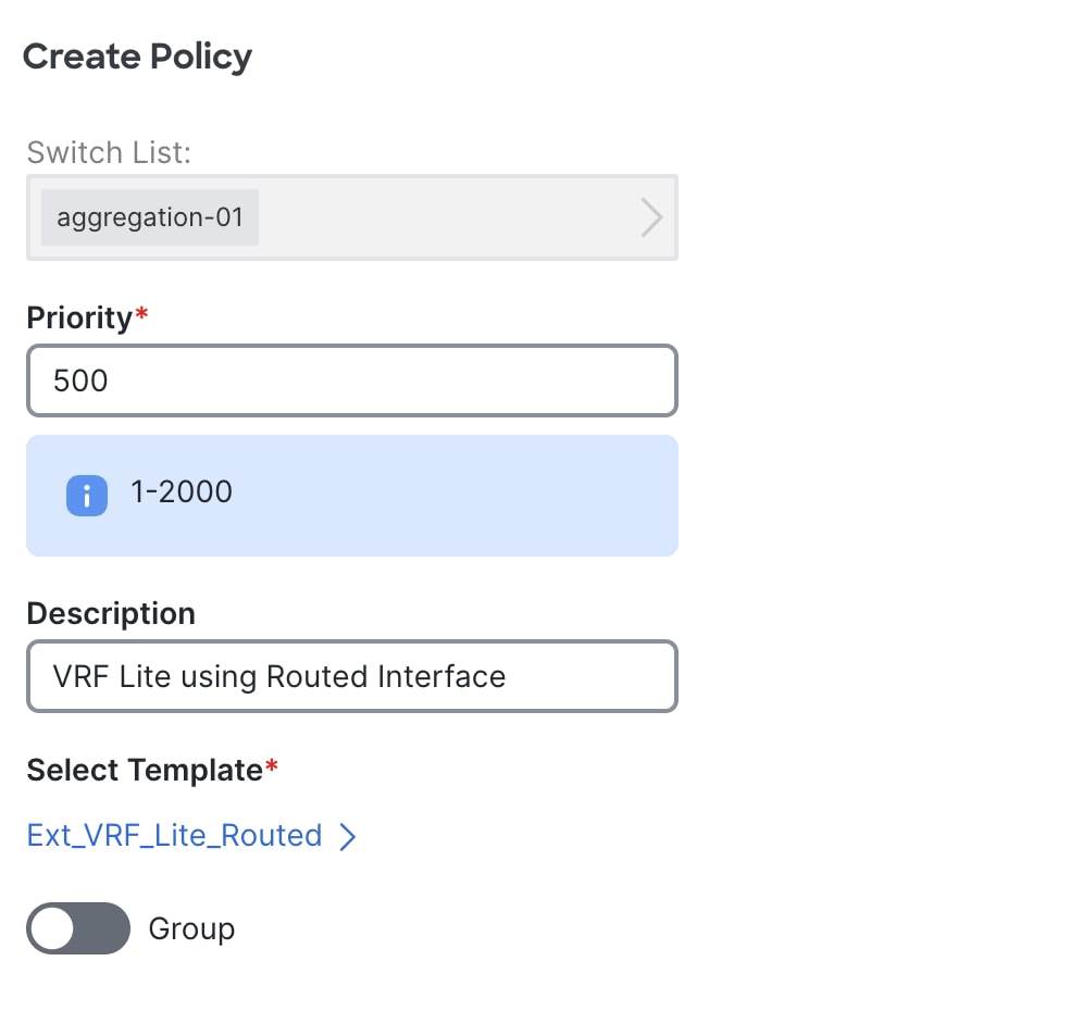
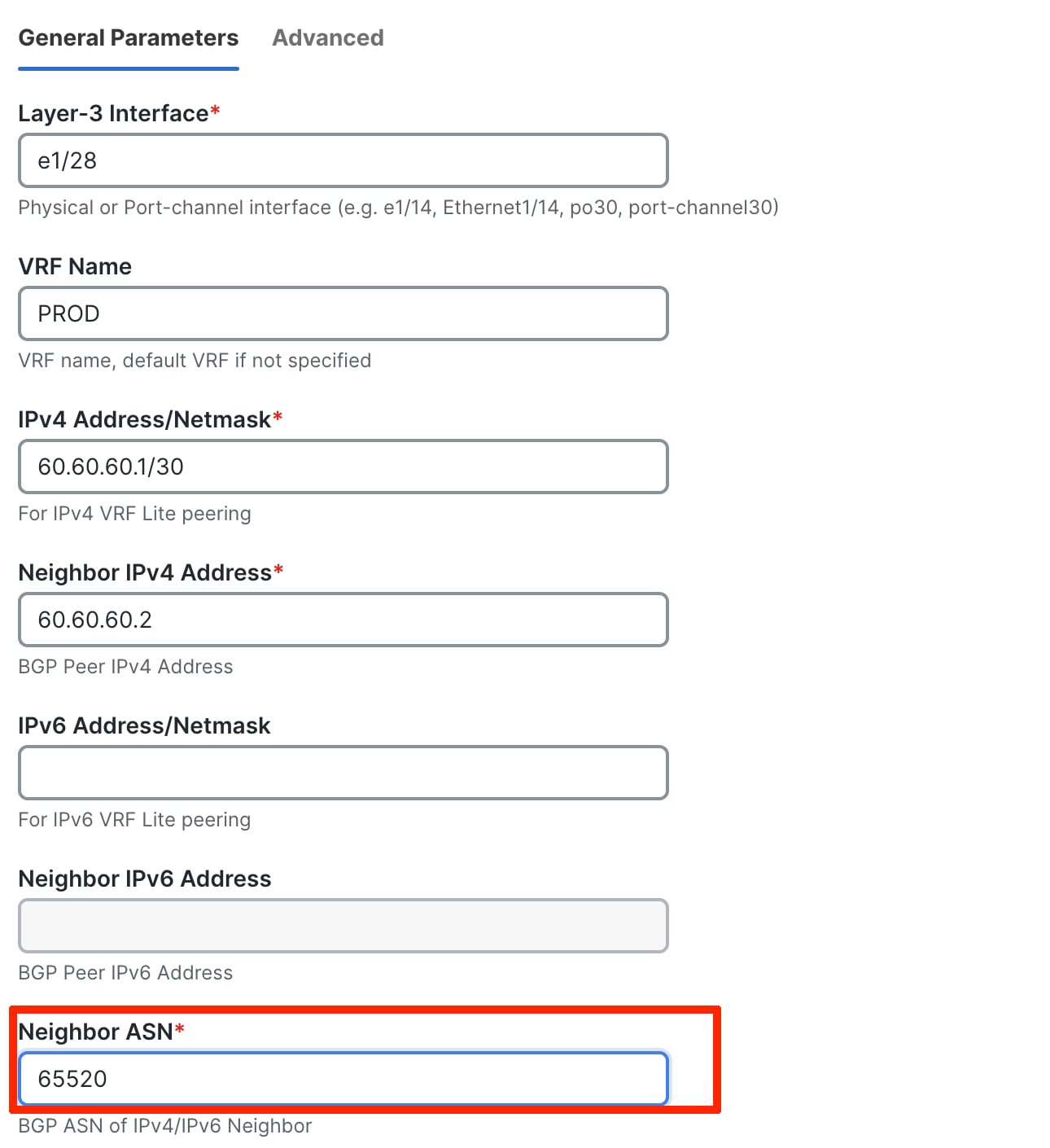
VRF-Lite Using Routed Interfaces or Port Channels
VRF-Lite over eBGP can also be achieved using routed interfaces or port channels on the Aggregation switch. In this case, you must manually apply a policy using the add policy per switch workflow, as described in the VRF-Lite Using SVIs section.
Use the Ext_VRF_Lite_Routed ND policy for routed interfaces. The following screenshots show usage of the policy:
 \
\
You must push the policy to the switches in Enhanced Classic LAN, and you must provision the equivalent configurations on the firewalls.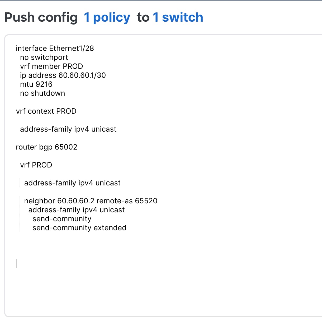
We recommend that you build newer classic Ethernet fabrics with Cisco Nexus 9000 switches in the Access, Aggregation, and Core layers, or that you have Cisco Nexus 9000 switches in the Access or Aggregation layer and use Cisco Nexus 7000 switches in the Core layer using the Enhanced Classic LAN fabric type. Cisco Nexus 7000 switches continue to be supported as a means to provide investment protection to customers who invested heavily in the platform and would like to continue to use the Cisco Nexus 7000 in the Core layer.
This section covers how networks comprising a mix of older platforms such as the Cisco Nexus 5000 and Cisco Nexus 6000 switches (which are not supported in an Enhanced Classic LAN) can co-exist with Cisco Nexus 7000 and 9000 switches in Enhanced Classic LAN. Use this option if you wish to refresh your older Cisco Nexus platforms with newer switches such as the Cisco Nexus 9000 switches. This can be a phased migration.
Note: To use an Enhanced Classic LAN Fabric, you must procure Cisco Nexus 9000 switches and have the cabling done for a 2 or 3 tier hierarchical network comprised of Cisco Nexus 9000 and 7000 switches, with vPCs at the Aggregation layer.
ND with Legacy Nexus Platforms
The following figures show topologies for use with legacy platforms:
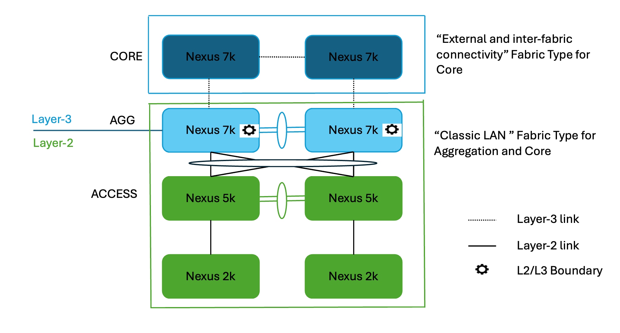
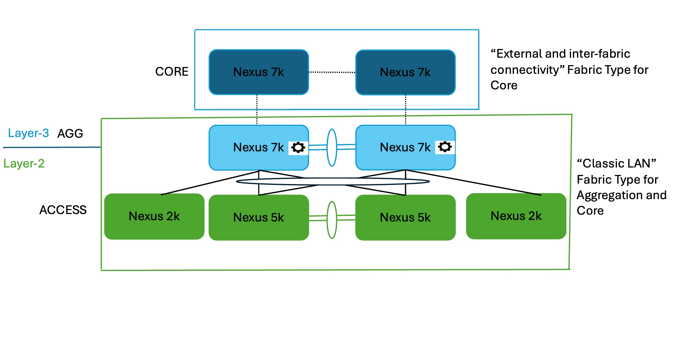
This is the starting point where you do not have any Cisco Nexus 9000 switches. Both types of topologies--with and without FEXes--are supported. You can have several combinations, such as Cisco Nexus 9000 switches at the Core and Aggregation layers instead of having only Cisco Nexus 7000 switches as shown in the figures. These topologies use Cisco Nexus 7000 switches with the assumption that you have not yet procured Cisco Nexus 9000 switches.
You must place Access and Aggregation switches in the "Classic LAN" fabric type, as Cisco Nexus 5000 switches are not supported in an Enhanced Classic LAN. This will be discussed in the following section.
For the Core layer with Cisco Nexus 7000 switches, follow the process in the For the Core Layer section and place the switches in the External and inter-fabric connectivity. After migration, this fabric will be used as the Core layer.
Create the fabric with the "Classic LAN" fabric type for these topologies, as this type supports all Cisco Nexus platforms.
Make sure the Fabric Monitor Mode check box does not have a check.

Save the fabric after you have chosen all of the parameters.
Next, discover the switches. This step does not disturb any configurations on the switch. All configurations in the switch are kept as-is: ND does not add nor delete any configuration. ND only discovers the switches and imports them into the fabric.
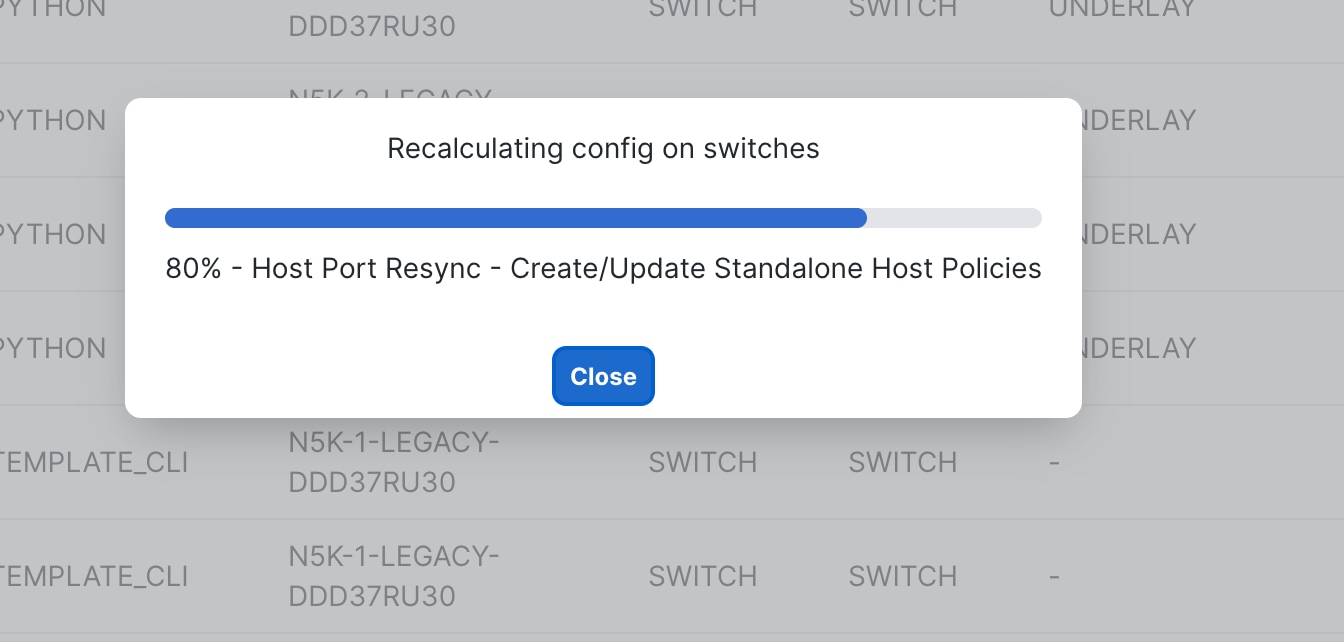
Because the Classic LAN fabric type does not support true brownfield, ND still does not have any intent that it learned from the switches while preserving all the configurations on the switch. ND has a feature called "Host Port Resync" that we recommend you use for switches that already have configurations. ND supports this feature for all Cisco NX-OS switches. Using Host Port Resync, ND learns all interface-related configurations and states for each switch, and these configurations become part of ND intent. After in the ND intent, you can incrementally manage the configurations from the controller using out-of-box or custom policies. Examples include vPC configurations, port channels, sub-interfaces, loopbacks, routed ports, host-facing ports, VLANs, and FEXes on the Access layer, and SVIs + VLAN + HSRP configurations on the Aggregation layer.
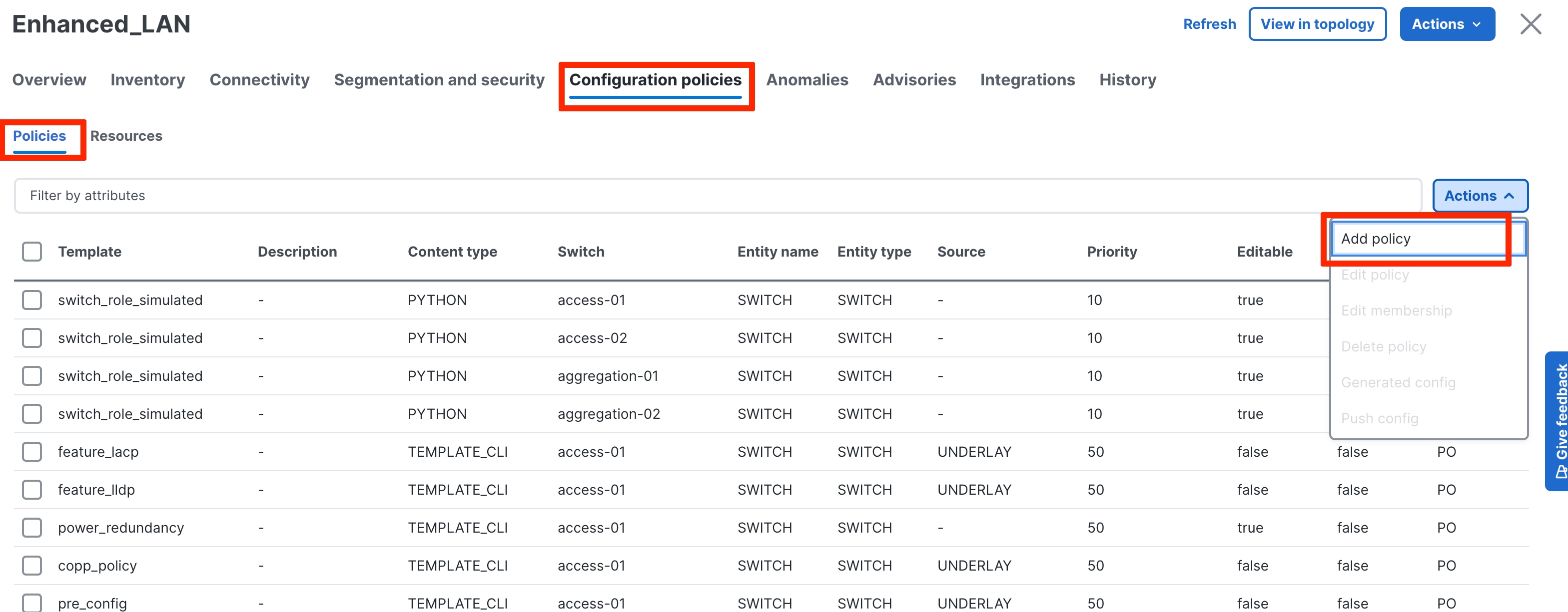
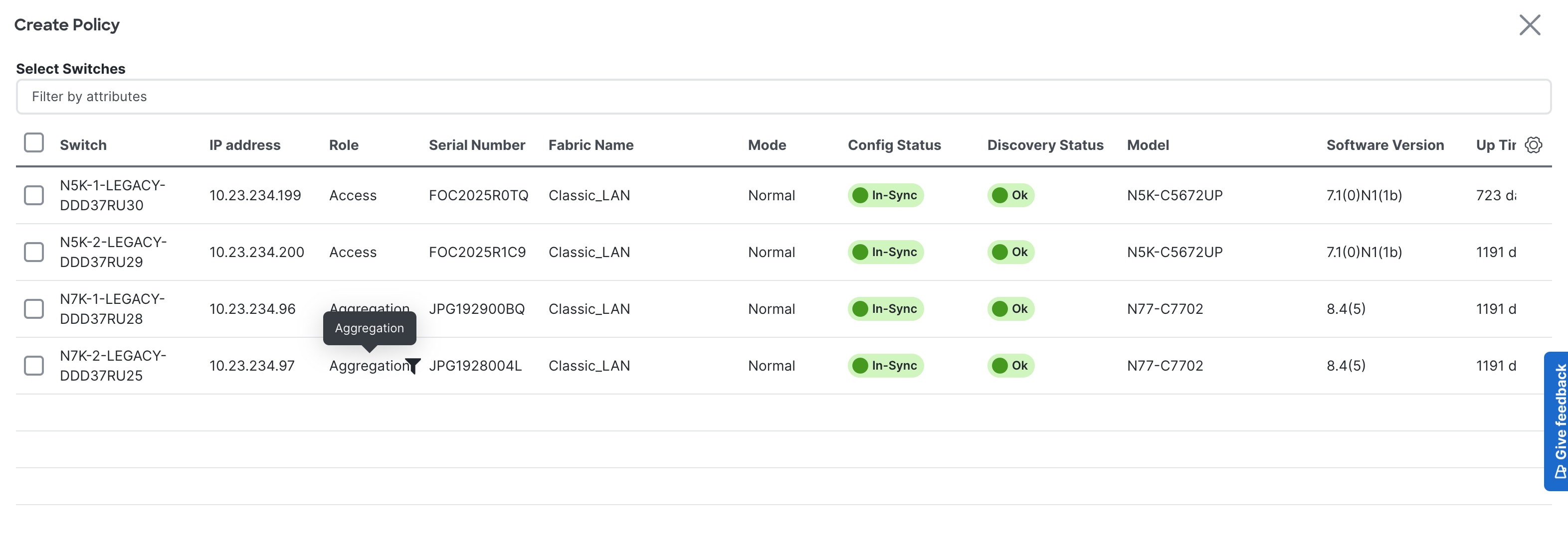
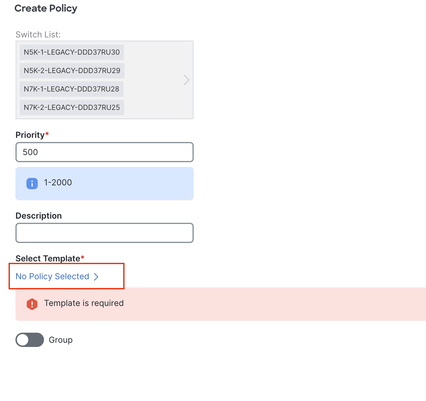
1. Navigate to Fabric > Configuration Policies > Actions > Add Policy.
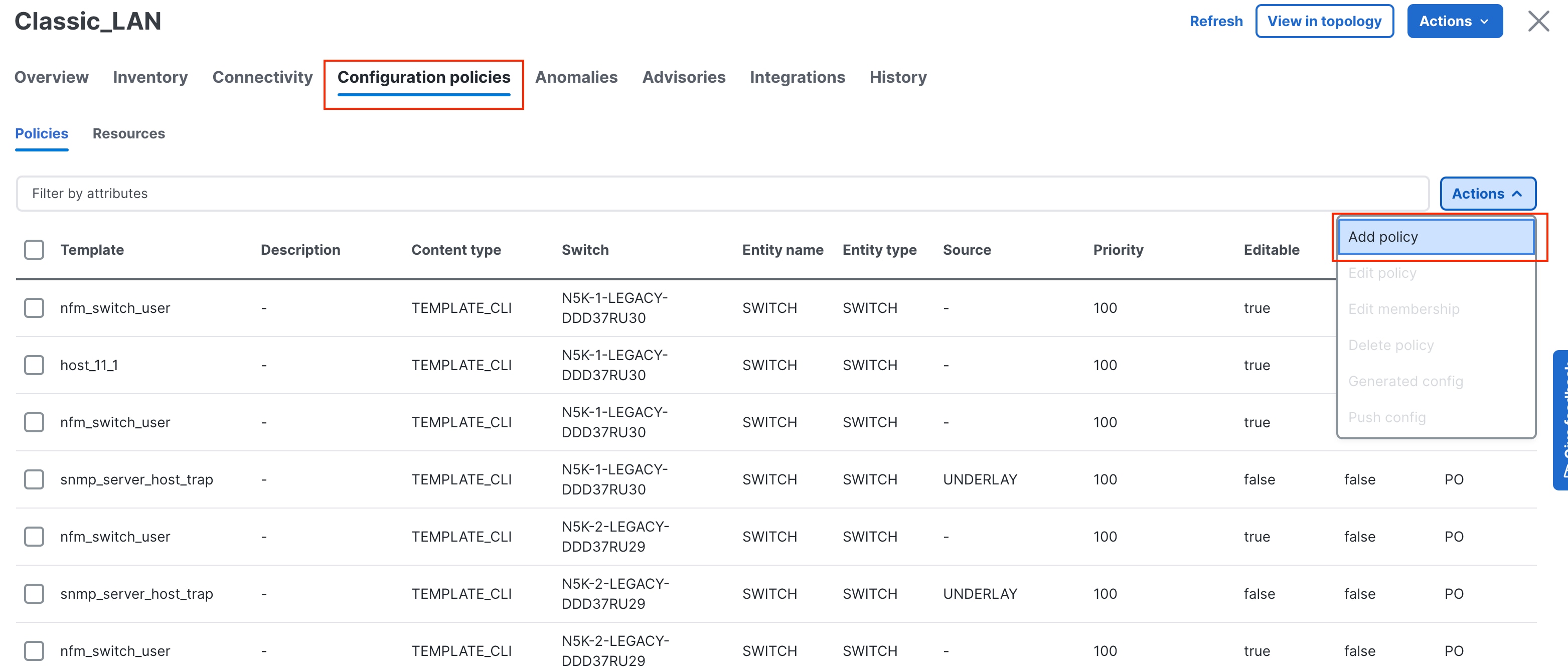
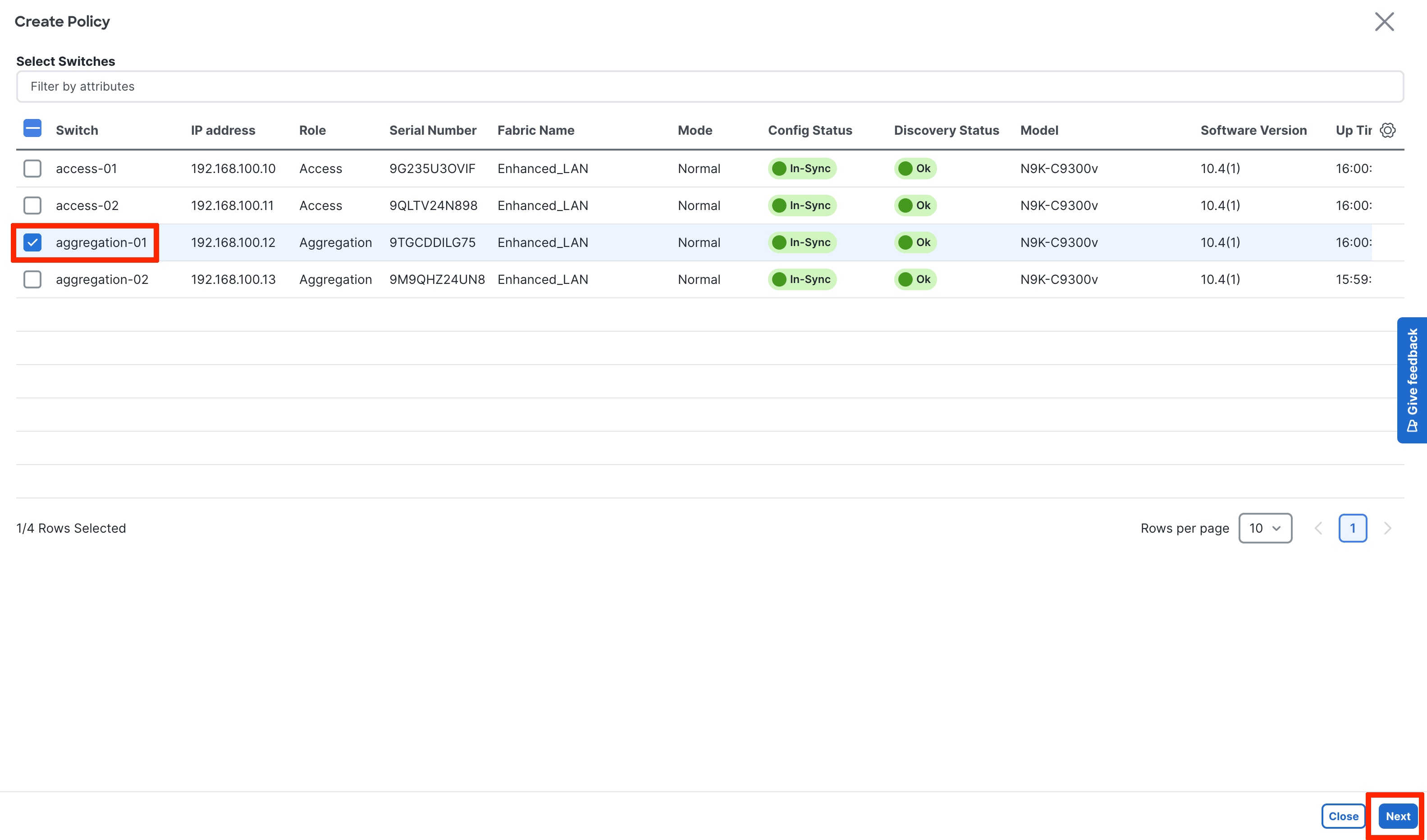
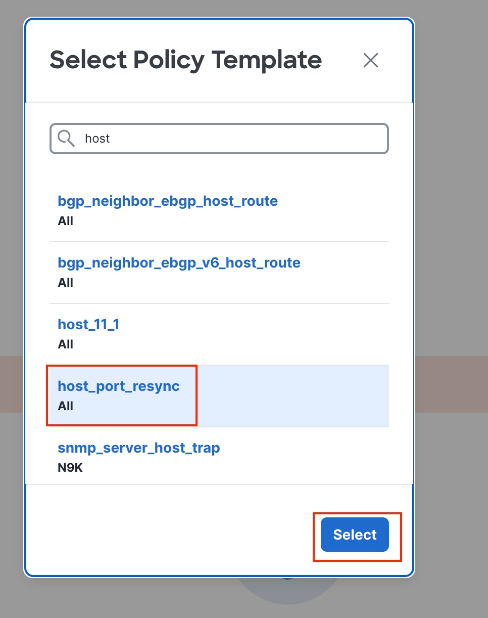
2. Select the switches and deploy the template host_port_resync.
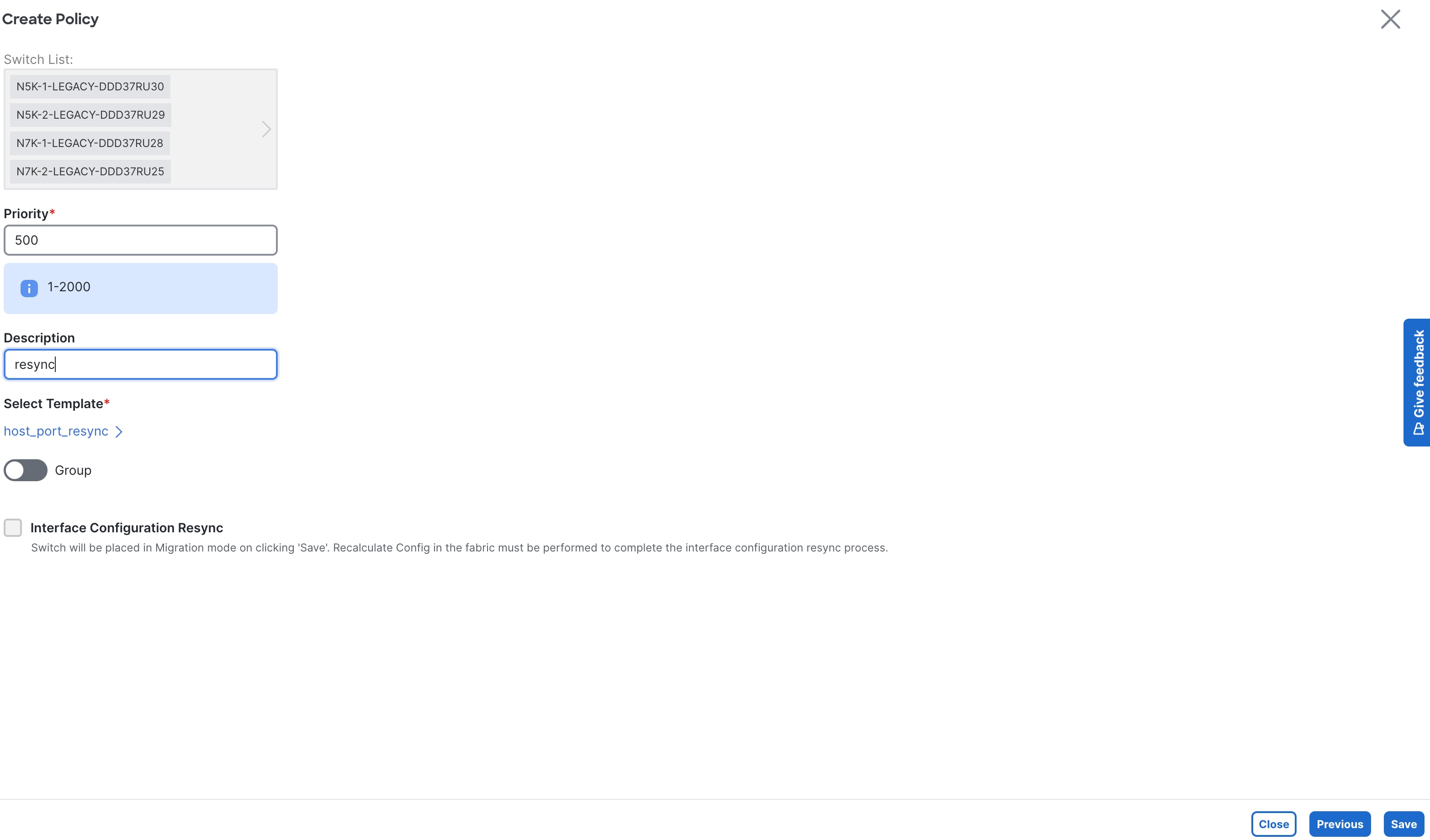
After ND deploys the template, ND starts learning Interface-specific intent and starts mapping interface configurations to existing policies. After this process completes, each interface becomes associated with a policy. Clicking on a policy shows the exact configuration present on the switch that has now been imported into ND.

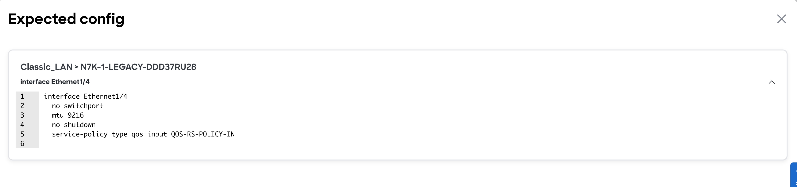
Hereafter, you can edit any of these Interface configurations, and ND pushes out the changes.
For all the other global configurations, such as routing or spanning-tree, because there was no support for a brownfield import, you must bring that intent manually into ND using out-of-box policies. There are a variety of policies available for Classic LAN use cases. ND has templates for all the following use cases and more:
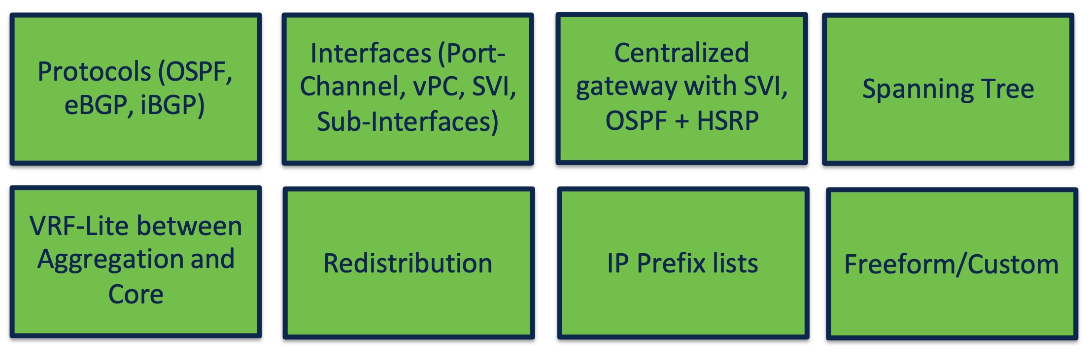
You must perform networks and VRF instance creation and the respective interface attachments using the appropriate policies.
This is how you can bring classic LAN networks with legacy Nexus platforms into ND and incrementally manage the networks using templates. All day 2 functionalities are available for the legacy classic LAN fabric as listed in the Using Enhanced Classic LAN section.
Note: Brownfield import plus end-to-end day 0 and day 1 automated workflows are available in the new Enhanced Classic LAN fabric type. However, the Cisco Nexus 2000, 5000, and 7000 platforms are EOL and EOS. Hence, we recommend that you refresh these platforms as soon as possible and start leveraging the benefits of this new fabric type in ND.
ND with Newer Cisco Nexus Platforms (Cisco Nexus 9000) Considering FEX
You can attach a FEX to an Access or Aggregation switch, or to both. You can transition all FEXes to Enhanced Classic LAN.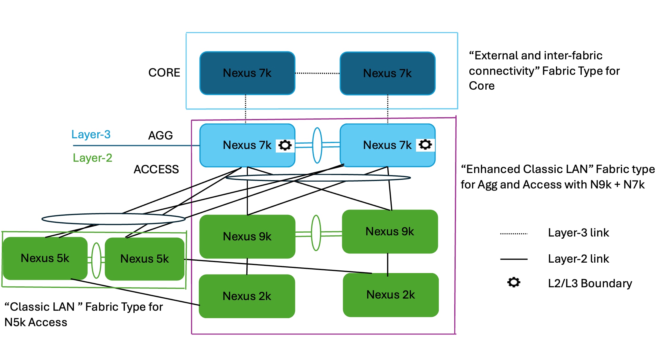
As you procure Cisco Nexus 9000 switches and you are ready to refresh the switches, you can build a best practice-based Classic Ethernet network from the ground up using the Enhanced Classic LAN fabric type with these Cisco Nexus 9000 switches at the Access layer (greenfield import) and Cisco Nexus 7000 switches at the Aggregation layer (brownfield Import). Alternatively, you can also replace the Cisco Nexus 7000 switches at the Aggregation layer with Cisco Nexus 9000 switches (greenfield import of the Cisco Nexus 9000 switches). You can also move FEXes to this new fabric and you can provision active-active/straight-through connectivity with the Cisco Nexus 9000 switches using ND.
You can leave the Cisco Nexus 5000 switches in the Classic LAN fabric type and manage the switches from there until they are ready to be retired. You can incrementally add any new Cisco Nexus 9000 switches to the Enhanced Classic LAN fabric in phases. ND provisions the configurations as long as you defined the role as discussed in the Day 0 for Classic LAN section. You can leave the Cisco Nexus 7000 Core switches in the External and inter-fabric connectivity fabric type to take advantage of auto VRF-Lite provisioning between the Aggregation and Core layers.
The process is summarized as follows:
1. You can keep the Cisco Nexus 5000 switches in the Classic LAN fabric as before and incrementally manage the switches using policies until they are ready to be retired.
2. As and when you procure Cisco Nexus 9000 switches, you can discover the switches in a new fabric using the Enhanced Classic LAN fabric type. You must define the roles, which will be a greenfield import with "Preserve Config = NO" setting. One-click vPC pairing options are available. ND pushes all relevant configurations with respect to roles and vPCs to these Cisco Nexus 9000 switches.
3. You can move Cisco Nexus 7000 switches as vPC pairs at the Aggregation layer in the Enhanced Classic LAN fabric. Because these are existing switches with configurations already in place, you can use brownfield import with "Preserve Config = YES" to do a non-disruptive migration of the Cisco Nexus 7000 switches from the Classic LAN fabric to Enhanced Classic LAN fabric. This preserves the original connectivity of the Cisco Nexus 7000 switches with the Cisco Nexus 5000 switches even though these are in two different fabrics. Hereafter, for any new configurations between Cisco Nexus 7000 and 9000 switches, you can use the Enhanced Classic LAN workflows as described in the Day 0 for Classic LAN and Day 1 for Classic LAN sections.
4. You can move FEXes to the Enhanced Classic LAN fabric with a brownfield import. ND preserves all the configurations between the Cisco Nexus 5000 switches and FEXes. You can provision any new configurations between FEXes and Cisco Nexus 9000 switches from the Enhanced Classic LAN fabric. ND supports the active-active and straight-through options.
5. The Cisco Nexus 7000 Core switches stay in the External and inter-fabric connectivity fabric type. ND preserves all configurations. If there is no VRF-Lite between the Aggregation and Core switches, now would be a good time to configure VRF-Lite using Enhanced Classic LAN day 1 workflows to adhere by Cisco best practices.
The idea is to move all supported platforms to Enhanced Classic LAN to leverage the end-to-end automated workflows while eventually refreshing the older Cisco Nexus platforms with Cisco Nexus 9000 switches. For more information about Enhanced Classic LAN workflows, see the Day 0 for Classic LAN, Day 1 for Classic LAN, and Day 2 for Classic LAN sections.
Layer 2/Layer 3 Demarcation at the Core Layer
The topologies discussed in the paper so far consider Layer 2/Layer 3 demarcation at the Aggregation layer. This is per Cisco recommended best practice for a classical Ethernet network. However, if the network is designed so that the Layer 2/Layer 3 boundary is at the Core layer instead, with the Access and Aggregation layers being Layer 2, you can still use Enhanced Classic LAN to leverage the new features and automated workflows.
The following figure shows the first variation of the topology with all Cisco Nexus 9000 and Cisco Nexus 7000 at all the layers:
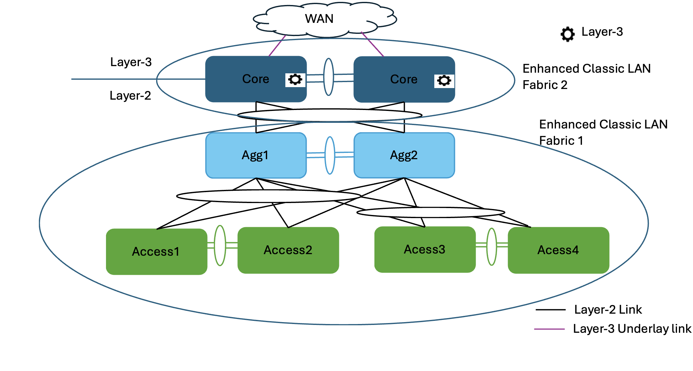
In this case, you can place the Access and Aggregation switches in "Enhanced Classic LAN Fabric1." You can set the options for FHRP and routing to NONE in the fabric settings and either keep everything else at the default values or customize the values. This will not provision any FHRP or routing configurations on both Access and Aggregation layers, making them all Layer 2. Set their roles appropriately as Access and Aggregation.
However, you must place the Core switches in "Enhanced Classic LAN Fabric2" with the role of "Aggregation." In the fabric settings, you can set the FHRP options to HSRP or VRRP. You can set the routing options based on the routing desired for external connectivity. ND considers this Aggregation switch as the Layer 2/Layer 3 boundary. You can place a WAN router as Core or Edge in a separate External and inter-fabric connectivity fabric to achieve VRF-Lite provisioning workflows with Fabric2 as discussed in the VRF-Lite Extension Between the Aggregation and Core/Edge Layers section.
A brownfield import works for both Fabrics 1 and 2. For Fabric 1, ND learns only Layer 2 networks, whereas for Fabric 2, ND learns Layer 3 Networks. You can perform any incremental provisioning using day 1 workflows from individual fabrics. You can also add both fabrics to a fabric group for better visualization.
For a greenfield, see the Day 0 for Classic LAN, Day 1 for Classic LAN, and Day 2 for Classic LAN sections.
Fabric 1 follows the Layer 2 network workflow. For more information, see the Layer 2 Network section. Fabric 2 follows the creation of Layer 3 network workflow with a custom or default VRF instance. For more information, see the Layer 3 Network with a Custom VRF Instance and Layer 3 Network in Default VRF Instance sections.
The following figure shows the second variation of the topology, when the Access layer consists of platforms unsupported in Enhanced Classic LAN (such as the Cisco Nexus 5000 switches), whereas the other layers consist of Cisco Nexus 9000 and 7000 switches:

In this case, you can place the Access switches in "Classic LAN Fabric1." You can incrementally manage these switches using policies until they are ready to retire. You must create and attach networks and VRF instances and configure vPCs and interface between Access and Aggregation switches using the appropriate policies.
You must place the Aggregation and Core switches in a separate "Enhanced Classic LAN Fabric2" with the Aggregation switch role set to "Access", and the Core switch role set to "Aggregation." In the fabric settings, you can set the FHRP options to HSRP or VRRP. You can set the routing options based on the routing desired for external connectivity. ND considers this Aggregation switch as the Layer 2/Layer 3 boundary. You can place a WAN router as Core or Edge in a separate External and inter-fabric connectivity fabric to achieve VRF-Lite provisioning workflows with Fabric2 as discussed in the VRF-Lite Extension Between the Aggregation and Core/Edge Layers section.
A brownfield import works for only Fabric 2. For Fabric 1, you can use a host port resync.
ND learns Layer 2 and Layer 3 networks for Fabric 2. You can perform any incremental provisioning using day 1 workflows from individual fabrics. You can also add both fabrics to a fabric group for better visualization.
For a greenfield, see the Day 0 for Classic LAN, Day 1 for Classic LAN, and Day 2 for Classic LAN sections.
Fabric 1 follows the creation of the Layer 2 network workflow using the policies in a Classic LAN. Fabric 2 follows the creation of a Layer 2 network at the Access layer. For more information, see the Layer 2 Network section. The Layer 3 network creation has a custom or default VRF instance in the Aggregation layer. For more information, see the Layer 3 Network with a Custom VRF Instance and Layer 3 Network in Default VRF Instance sections.
Migration from Classic LAN and VXLAN Networks
VXLAN as a technology has various benefits over traditional hierarchical Classical Ethernet networks. Along with being the industry-standard and widely adopted, VXLAN is:
● Proven and scalable
● Improves network performance
● Increases network reliability
● Simplifies network management and IP address mobility
● Helps with segmentation and multi-tenancy
ND highly simplifies VXLAN greenfield (and brownfield) deployment with a few clicks, using the "Data center VXLAN EVPN" fabric type while adhering to best practices. You can find the end-to-end provisioning of a VXLAN using ND in the Nexus Dashboard, Release 4.1.x User Content. As you plan for this adoption, it is imperative that you must be able to configure the Enhanced Classic LAN and VXLAN fabrics within the same ND instance until the Classic network is ready to be retired.
To plan for migration from Enhanced Classic LAN to VXLAN, you can consider the following topologies:
● Topology1: Layer 2 and Layer 3 connectivity between Aggregation switches in a brownfield Enhanced Classic LAN and border leaf switches in a greenfield VXLAN fabric.
This approach is viable if the legacy network and the new VXLAN fabric are geographically co-located.
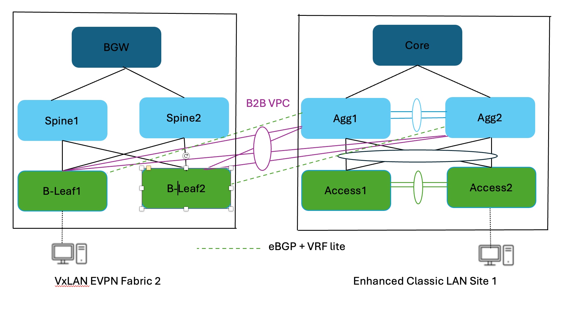
● Topology 2: Layer 2 and Layer 3 connectivity between Aggregation switches in an Enhanced Classic LAN and a border gateway in a VXLAN fabric that extends to border gateways in a greenfield VXLAN fabric.
This approach is viable if the Legacy network and the new VXLAN Fabric are geographically dispersed.
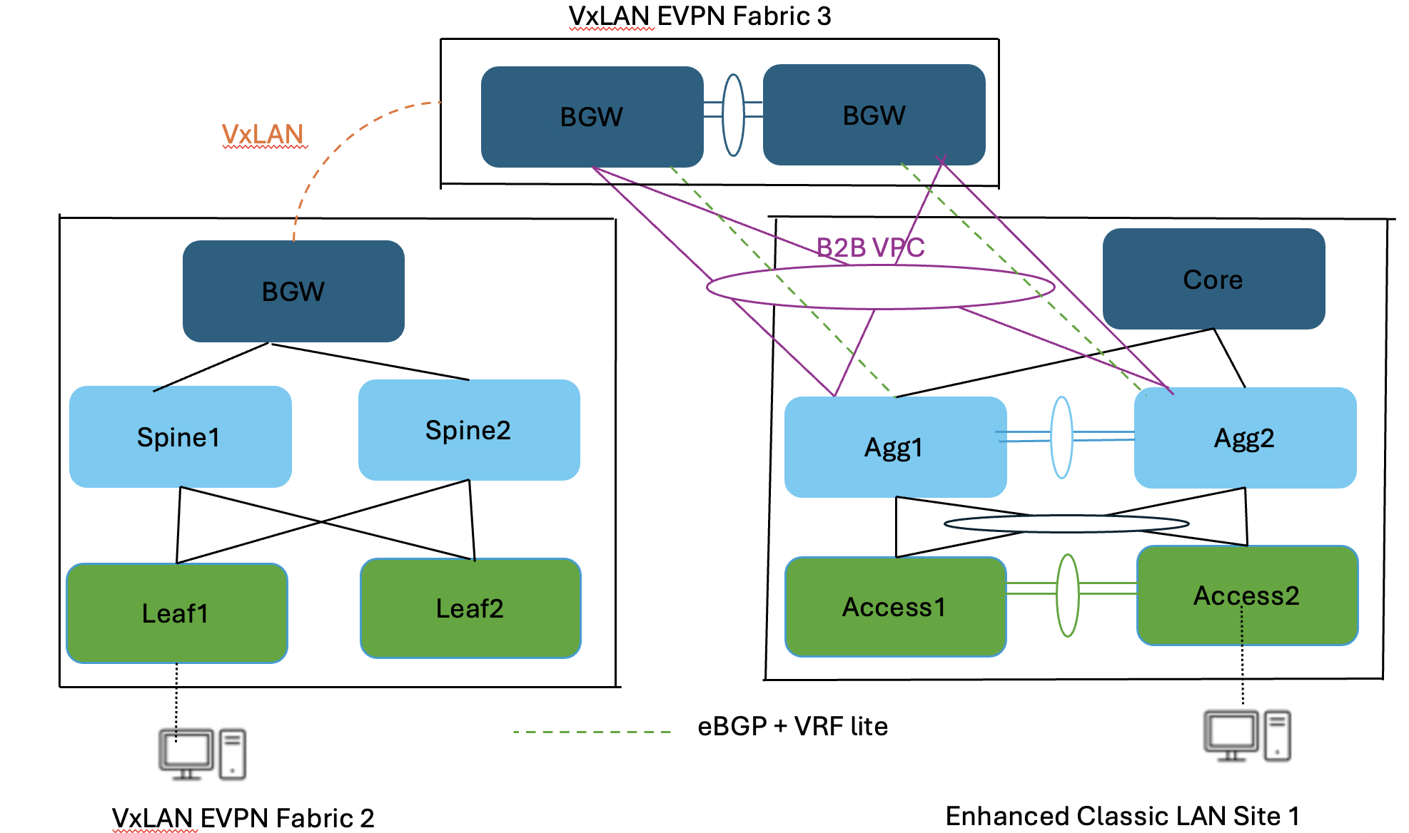
In both the topologies, you must make sure there is Layer 2 and Layer 3 connectivity between Aggregations in the brownfield site and border leaf switch or border gateway in the VXLAN site.
You must provision Layer 2 connectivity, such as using vPCs, port channels, and Layer 3 connectivity with VRF-Lite, using policies in ND. For information about using ND for provisioning Layer 2 connectivity, see:
● "Adding InterfacesAdding Interfaces" section in the Nexus Dashboard Fabric Controller, Release 12.2.2/12.2.3 User Content for LAN. The same configuration applies to 4.1.1 release.
With ND release 4.1.1, you can make Enhanced Classic LAN (ECL) part of a VXLAN EVPN Multi-Site fabric along with VXLAN fabrics. This allows you to configure VXLAN EVPN Multi-Site for DCI between Enhanced Classic LAN and VXLAN fabrics. This helps with coexistence and migration to VXLAN.
The following figure shows a topology for DCI:
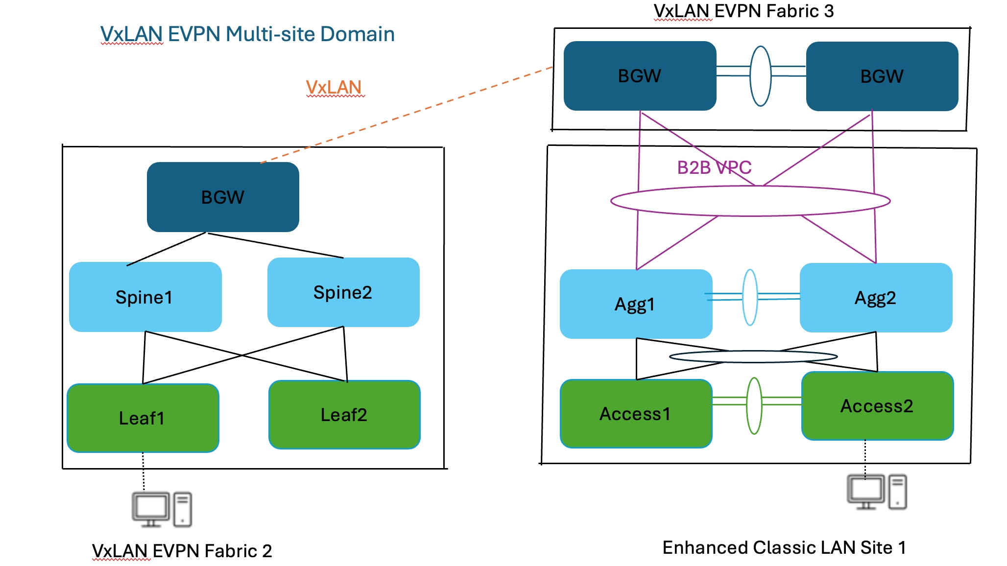
You can use the Data center VXLAN EVPN fabric type for a greenfield VXLAN fabric consisting of a leaf-spine-border Gateway (Fabric2) as well as border gateways (BGWs) (Fabric3) connecting the Aggregation switches (Enhanced Classic LAN Site1)—the existing brownfield Classic LAN legacy site. The border gateways allow for VXLAN EVPN Multi-Site.
Adding all 3 fabrics in a VXLAN EVPN Multi-Site domain allows for Layer 2 and Layer 3 extension of networks and VRF instances between:
● Border gateways in Fabric3 and Aggregation switches in the Enhanced Classic LAN Site1
● Border gateways in Fabric3 and border gateways in the greenfield VXLAN fabric Fabric1
You can use ND for:
● Importing and discovering existing brownfield classic Ethernet networks using Enhanced Classic LAN
● Setting up the greenfield VXLAN BGP EVPN fabric using POAP, bootstrap, or switch IP address discovery with border gateways
● VXLAN EVPN Multi-Site for Layer 2 and Layer 3 extension of networks between Classic and VXLAN fabrics
Enhanced Classic LAN uses the centralized gateway concept with FHRP, whereas VXLAN uses a distributed anycast gateway (DAG) concept. For coexistence of these two disparate types of gateways, that is keeping both running at the same time, Cisco NX-OS introduced a new feature starting in the 10.2(3) release as described in the "Default Gateway Coexistence of HSRP and Anycast Gateway (VXLAN EVPN)" chapter of the Cisco Nexus 9000 Series NX-OS VXLAN Configuration Guide, Release 10.6(x). As long as the switches are running the NX-OS 10.2(3) release or later, both DAG and FHRP gateways can coexist, and you can use the ND 12.1(3) release or later to provision the DAG and FHRP gateways. For the NX-OS 10.2(3) release and earlier, only one kind of gateway can exist. Hence, you must bring down the gateway for workloads from the brownfield Enhanced Classic LAN network and move the gateway to the greenfield VXLAN fabric with anycast gateway.
The Migrating Classic Ethernet Environments to VXLAN BGP EVPN whitepaper provides all the details from connectivity to migration/coexistence and the configurations required, and how you can use ND for performing these procedures.
This whitepaper discusses the Enhanced Classic LAN in the ND 4.1.1 release, which is when this solution was first introduced. Although the Enhanced Classic LAN fabric type provides an end-to-end workflow for provisioning a 2 or 3 tier classical Ethernet network, we recommend that you migrate to a VXLAN-based overlay network due to all the benefits such a network provides over Classic Ethernet. As described in this document, if you are running networks with Cisco Nexus 5000 or 6000 switches, we highly recommend that you refresh these End-of-Life (EOL) platforms to Cisco Nexus 9000 switches to take advantage of the latest hardware and software features.