Migrating Classic Ethernet Environments to VXLAN BGP EVPN
Available Languages
Bias-Free Language
The documentation set for this product strives to use bias-free language. For the purposes of this documentation set, bias-free is defined as language that does not imply discrimination based on age, disability, gender, racial identity, ethnic identity, sexual orientation, socioeconomic status, and intersectionality. Exceptions may be present in the documentation due to language that is hardcoded in the user interfaces of the product software, language used based on RFP documentation, or language that is used by a referenced third-party product. Learn more about how Cisco is using Inclusive Language.
- US/Canada 800-553-2447
- Worldwide Support Phone Numbers
- All Tools
 Feedback
 Feedback
Introduction
This document describes the migration from a Classic Ethernet ”brownfield” environment to a ”greenfield” virtual extensible LAN (VXLAN) Border Gateway Protocol (BGP) Ethernet Virtual Private Network (EVPN) fabric. The main focus is extending the Classic Ethernet network to a VXLAN BGP EVPN fabric, including migration of the first-hop gateway, which in turn facilitates moving workloads from the old network to a new one. The migration use case includes connectivity to an external Layer 3 network.
This document covers the concepts of interconnecting a Classic Ethernet brownfield environment with a new VXLAN BGP EVPN fabric.
Limited background information is included on other related components whose understanding is required for the migration. (See the “For more information” section at the end of this document for where to find background information on VXLAN BGP EVPN, Classic Ethernet, and Cisco Virtual Port Channel.)
Note: The documentation set for this product strives to use bias-free language. For the purposes of this documentation set, bias-free is defined as language that does not imply discrimination based on age, disability, gender, racial identity, ethnic identity, sexual orientation, socioeconomic status, and intersectionality. Exceptions may be present in the documentation due to language that is hardcoded in the user interfaces of the product software, language used based on RFP documentation, or language that is used by a referenced third-party product.
Migrating a Brownfield Network
The migration described in this document is often referred to as “Virtual Port Channel (VPC) back-to-back” and consists of interconnecting an existing brownfield network (based on Spanning Tree Protocol, VPC, or FabricPath technologies) to a newly developed VXLAN BGP EVPN fabric, with the end goal of migrating applications or workloads between those environments.
Figure 1 shows the migration methodology, highlighting the major steps required for performing the migration of applications.
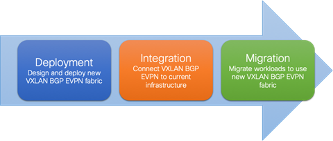
Figure 1 Migration Steps
The steps of the migration methodology are as follows:
1. First is the design and deployment of the new VXLAN BGP EVPN environment (greenfield network). It is likely that such a deployment will initially be small, with plans to grow over time as the number of workloads go higher. A typical VXLAN BGP EVPN fabric consists traditionally of a leaf-and-spine topology.
2. Second is the integration between the existing data center network infrastructure (called the brownfield network) and the new VXLAN BGP EVPN fabric. Layer 2 and Layer 3 connectivity between the two networks is required for successful application and workload migration across the two network infrastructures.
3. Third and final step consists of migrating workloads between the brownfield and the greenfield network. It is likely that this application migration process takes several months to complete, depending on the number and complexity of the applications being migrated. The communication between the greenfield and brownfield networks, across the Layer 2 and Layer 3 connections established in step 2, are used during this phase.
Through the migration steps, the placement of the first-hop gateway must be carefully considered. Prior to NX-OS Release 10.2(3), it was recommended place the first-hop gateway function on the Greenfield network for newly deployed Virtual LANs (VLANs) and associated IP subnets.
For VLANs and associated IP subnets that are migrated from the brownfield to the greenfield network, the timing of the first-hop gateway migration can be chosen based on the following criteria:
1. The time period when the majority of the workloads are migrated to the greenfield network.
2. Premigration of the first workload
3. Postmigration of the last workload
The correct timing depends on many factors, with the most critical being when a possible disruption to the network can be accommodated.
Starting from NX-OS Release 10.2(3), a new functionality is introduced allowing the coexistence of the FHRP default gateway configuration in the legacy network and of the Distributed Anycast Gateway (DAG) configuration in the greenfield VXLAN EVPN fabric. Therefore, this has now become the best practice configuration for migrating endpoints between the two networks. For more information, see Default Gateway Coexistence of HSRP and Anycast Gateway (VXLAN EVPN) (NX-OS Release 10.2(3) and later).
Layer 2 Interconnection
Interconnecting the brownfield network with the greenfield network via Layer 2 is crucial to facilitate seamless workload migration.
Note: When seamless workload migration is not required, a Layer 2 interconnect between brownfield and greenfield is not necessary. In these cases, a per-VLAN or per-IP subnet approach can be chosen for the migration. This approach does not provide a seamless migration, but it is viable in case it is beneficial.
Figure 2 shows the brownfield-greenfield interconnection, which highlights the major components of the migration approach.

Figure 2 Overview: Brownfield-greenfield Interconnection
For the Layer 2 interconnection, we establish a double-sided VPC (Virtual Port-Channel for Classic Ethernet) between a pair of nodes in the greenfield (VXLAN) and brownfield (Classic Ethernet) networks. A Classic Ethernet network is the focus of the migration. Interconnect the VPC domain with the VPC domain in the VXLAN BGP EVPN fabric. The double-sided VPC connection between the two network infrastructures allows a Layer 2 extension without risking any Layer 2 loop by maintaining all VPC links for actively forwarding traffic.
The nodes chosen in the greenfield network can represent a border node or any other switch that provides the VXLAN BGP EVPN tunnel endpoint functionality. In the brownfield network, the nodes for the interconnection should represent the Layer 2–Layer 3 demarcation. In the case of Classic Ethernet, the Layer 2–Layer 3 demarcation is found at various locations, depending on the topology and the chosen first-hop gateway mode. The commonly found Classic Ethernet with VPC deployments is Access-Aggregation topologies with first-hop gateway at the Aggregation nodes using VPC and traditional First Hop Routing Protocol (FHRP) – Hot Standby Router Protocol (HSRP)
Figures 3–5 depict these topologies and associated gateway placement options for the brownfield network.
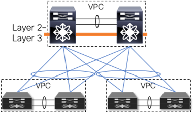
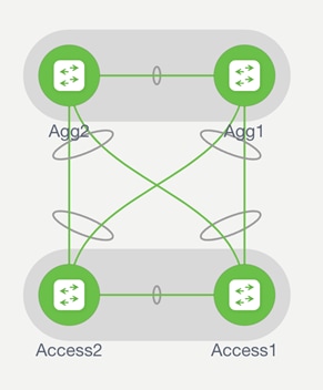
Figure 3 Access-aggregation with first-hop gateway at aggregation
The access-aggregation topology with VPC for Classic Ethernet shown in Figure 3 represents a brownfield network that was built with Spanning Tree Protocol or VPC technology.
The Layer 2–Layer 3 interconnection between the brownfield and the greenfield network would be placed at the aggregation nodes.
VPC Considerations
VPC is typically used in the access or aggregation layer of a network. At the access layer, it is used for active-active connectivity from endpoints (server, switch, NAS storage device, etc.) to the VPC domain. At the aggregation layer, VPC is used for providing both active-active connectivity from access layer to the aggregation VPC domain, and active-active connectivity to the first-hop gateway along with HSRP or VRRP, for the Layer 2–Layer 3 demarcation.
However, because VPC provides capabilities to build a loop-free topology, it is also commonly used to interconnect two separate networks at Layer 2, allowing extension of the Layer 2 domain. For the scope of this document, VPC is used to interconnect the brownfield Classic Ethernet network with the greenfield VXLAN BGP EVPN network.

Figure 4 Double-sided VPC (loop-free topology)
Note: Using VPC for Layer 2 interconnection between the brownfield and greenfield networks makes all existing VPC best practices applicable.
VPC Configuration
The configuration examples provided in this section highlight key concepts for interconnecting brownfield and greenfield networks.
Classic Ethernet VPC
The configuration example below shows a Classic Ethernet VPC domain in a brownfield network. Port-Channel 1 comprising member ports Ethernet 1/47 and 1/48, represents the VPC peer-link, which is required to be an IEEE 802.1Q trunk (switchport mode trunk). In addition, a Port-Channel 20 with VPC ID 20 is configured to provide Layer 2 interconnection to the VXLAN BGP EVPN greenfield network. The Virtual Port-Channel 20 has Ethernet interface 1/1 as a member port for the IEEE 802.1Q trunk and uses Link Aggregation Control Protocol (LACP).
Note: With LACP, the VPC domain ID should be different in the brownfield and greenfield networks.
Classic Ethernet Node 1
vpc domain 20
peer-switch
peer-gateway
ipv6 nd synchronize
ip arp synchronize
!
interface port-channel 1
description VPC peer-link
switchport mode trunk
spanning-tree port type network
vpc peer-link
!
interface port-channel 20
description virtual port-channel to greenfield
switchport mode trunk
spanning-tree port type normal
spanning-tree guard root
mtu 9216
storm-control broadcast level 5.00
storm-control multicast level 5.00
vpc 20
!
interface Ethernet 1/1
description member port of port-channel/VPC 20
switchport mode trunk
channel-group 20 mode active
!
interface ethernet 1/47
description member port VPC peer-link
switchport mode trunk
channel-group 1
!
interface ethernet 1/48
description member port VPC peer-link
switchport mode trunk
channel-group 1
Classic Ethernet Node 2
vpc domain 20
peer-switch
peer-gateway
ipv6 nd synchronize
ip arp synchronize
!
interface port-channel 1
description VPC peer-link
switchport mode trunk
spanning-tree port type network
vpc peer-link
!
interface port-channel 20
description virtual port-channel to greenfield
switchport mode trunk
spanning-tree port type normal
spanning-tree guard root
mtu 9216
storm-control broadcast level 5.00
storm-control multicast level 5.00
vpc 20
!
interface Ethernet 1/1
description member port of port-channel/VPC 10
switchport mode trunk
channel-group 20 mode active
!
interface ethernet 1/47
description member port VPC peer-link
switchport mode trunk
channel-group 1
!
interface ethernet 1/48
description Member port VPC peer-link
switchport mode trunk
channel-group 1
VXLAN BGP EVPN VPC
The following configuration example shows a Cisco VXLAN BGP EVPN VPC domain in the greenfield network. The individual VXLAN tunnel endpoint (VTEP) IP addresses are 10.10.10.11 and 10.10.10.12, for nodes 1 and 2, respectively, and the anycast VTEP IP address is 10.10.10.100, shared across both nodes. Port-channel 1 represents the VPC peer-link, which is a traditional IEEE 802.1Q trunk (switchport mode trunk) with participating interfaces Ethernet 1/47 and 1/48. In addition, a port-channel with VPC ID 10 is configured to provide the Layer 2 interconnection to the brownfield Classic Ethernet network. The virtual port-channel 10 has interface Ethernet 1/1 as a member port for the IEEE 802.1Q trunk and uses LACP.
Note: With LACP, the VPC domain ID should be different in the brownfield and greenfield network.
VXLAN BGP EVPN Node 1
vpc domain 10
peer-switch
peer-gateway
ipv6 nd synchronize
ip arp synchronize
!
interface loopback1
description loopback for VTEP (NVE)
ip address 10.10.10.11/32
ip address 10.10.10.100/32 secondary
!
interface port-channel 1
description VPC peer-link
switchport mode trunk
spanning-tree port type network
vpc peer-link
!
interface port-channel 10
description virtual port-channel to brownfield
switchport mode trunk
spanning-tree port type normal
mtu 9216
vpc 10
!
interface Ethernet 1/1
description member port of port-channel/VPC 10
switchport mode trunk
channel-group 10 mode active
!
interface ethernet 1/47
description member port VPC peer-link
switchport mode trunk
channel-group 1
!
interface ethernet 1/48
description member port VPC peer-link
switchport mode trunk
channel-group 1
VXLAN BGP EVPN Node 2
vpc domain 10
peer-switch
peer-gateway
ipv6 nd synchronize
ip arp synchronize
!
interface loopback1
description loopback for VTEP (NVE)
ip address 10.10.10.12/32
ip address 10.10.10.100/32 secondary
!
interface port-channel 1
description VPC peer-link
switchport mode trunk
spanning-tree port type network
vpc peer-link
!
interface port-channel 10
description virtual port-channel to brownfield
switchport mode trunk
spanning-tree port type normal
mtu 9216
vpc 10
!
interface Ethernet 1/1
description member port of port-channel/VPC 10
switchport mode trunk
channel-group 10 mode active
!
interface ethernet 1/47
description member port VPC peer-link
switchport mode trunk
channel-group 1
!
interface ethernet 1/48
description member port VPC peer-link
switchport mode trunk
channel-group 1
Spanning-Tree Considerations
VPC for Classic Ethernet supports not only endpoint connections but also supports connections of entire Classic Ethernet networks running Spanning Tree Protocol. Commonly, when a Classic Ethernet network is built, the Spanning Tree root is placed at the Aggregation nodes.
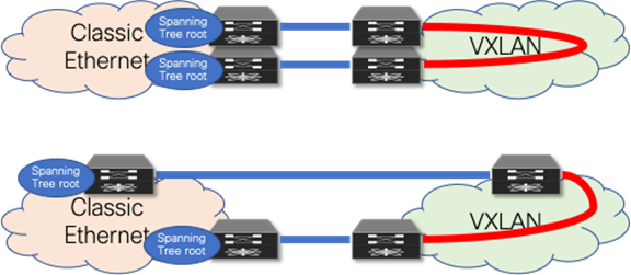
Figure 5 Layer 2 interconnect with loop
As opposed to a Classic Ethernet network, a VXLAN BGP EVPN network has no specific requirement for Spanning Tree. Even as the best practice dictates that every VTEP should be performing as the Spanning Tree root, the VXLAN overlay itself is not aware of Bridge Protocol Data Units (BPDUs) or Spanning Tree–related forwarding state, nor will it forward them. With the Classic Ethernet network being the Spanning Tree root, the connected VTEPs should have the Spanning Tree root port toward the Classic Ethernet network. As a result, it is crucial that only a single, logical, or physical, active Layer 2 connections between the brownfield and greenfield network be active. Otherwise, a Layer 2 loop exists, as shown in Figure 5. The single active connection can be achieved using a double-sided VPC connection or by manual VLAN distribution (see Figure 6).
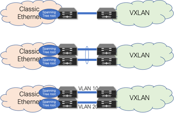
Figure 6 Loop-free Layer 2 interconnect (options)
Note: Spanning Tree BPDUs from the Classic Ethernet network are sent towards the VTEPs, but the VXLAN overlay does not forward the BPDUs, nor does it perform any blocking action on the VXLAN tunnel. As a result, a Layer 2 Loop can occur, so proper design of the Layer 2 interconnect is critical.
Spanning Tree Configuration
The examples in this section highlight key concepts for interconnecting the brownfield and greenfield networks as well as the Spanning Tree caveats. All best practices for Spanning Tree with Classic Ethernet VPC and VXLAN BGP EVPN VPC are applicable, whether or not shown in these examples.
VXLAN BGP EVPN Spanning Tree and VPC
The example below shows a Cisco VXLAN BGP EVPN VPC domain in the greenfield network. The individual VTEP IP addresses are 10.10.10.11 and 10.10.10.12, for nodes 1 and 2, respectively, and the anycast VTEP IP address is 10.10.10.100, shared across both VXLAN nodes. The Spanning Tree priority is set on both nodes to be the same and an inferior value to the Classic Ethernet nodes, so that the Classic Ethernet nodes the Spanning Tree root.
Note: The VXLAN Overlay does not forward BPDUs, hence no Spanning Tree blocking ports exist, specifically for the overlay. Best practice suggests assigning the lowest Spanning Tree priority (root) to all the VXLAN BGP EVPN nodes. However, during the migration phase from the Classic Ethernet network to VXLAN, it's important to maintain the Classic Ethernet network as the root to minimize downtime during migration. Otherwise, configuring VXLAN BGP EVPN nodes with a lower priority will trigger STP reconvergence, resulting in brief downtime for targeted VLANs.
VXLAN BGP EVPN Node 1
vpc domain 10
peer-switch
peer-gateway
ipv6 nd synchronize
ip arp synchronize
!
interface loopback1
description loopback for VTEP (NVE)
ip address 10.10.10.11/32
ip address 10.10.10.100/32 secondary
!
spanning-tree vlan 1-4094 priority 61440
VXLAN BGP EVPN Node 2
vpc domain 10
peer-switch
peer-gateway
ipv6 nd synchronize
ip arp synchronize
!
interface loopback1
description loopback for VTEP (NVE)
ip address 10.10.10.12/32
ip address 10.10.10.100/32 secondary
!
spanning-tree vlan 1-4094 priority 61440
Note: Spanning Tree root is specific to the Nexus 7000s implementation. This is a mismatch to the requirement for interconnecting with a Classic Ethernet network. So, a BPDU filter must be used on the Layer 2 interconnecting interfaces. Alternate methods are valid if the requirement for Spanning Tree root on the Classic Ethernet and VXLAN side are met.
VLAN Mapping
In Classic Ethernet, with or without VPC, all VLANs must be configured to allow the respective Layer 2 traffic to be forwarded from one Classic Ethernet enabled node to another. Primarily, Classic Ethernet uses the traditional 12-bit VLAN namespace (Figure 7), which allows for approximately 4000 VLANs.
Note: When traffic exits an Ethernet port, traditional Ethernet and VLAN semantics are used (Figure 7). Multiple VLANs can be transported over a single IEEE 802.1Q trunk toward an endpoint or Ethernet switch.
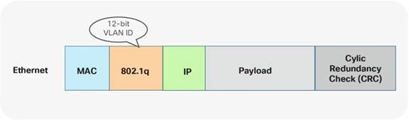
Figure 7 Ethernet namespace
With VXLAN, with or without VPC, VLANs do not exist between the VTEPs. Instead of using the VLAN namespace within a VXLAN enabled fabric, mapping is done on the nodes performing the VTEP function. At the VTEP, the Ethernet VLAN identifier is mapped to a VXLAN Network Identifier (VNI) through configuration. As a result, the VLAN itself becomes locally significant to the VTEP, whereas when communication is transported between VTEPs, a different namespace is used. VXLAN provides a more extensive namespace by allowing approximately 16 million unique identifiers in its 24-bit namespace Figure 8.
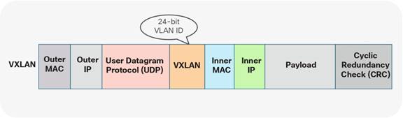
Figure 8 VXLAN namespace
Given these different approaches taken by Classic Ethernet and the VXLAN BGP EVPN fabrics, the VLAN mapping is not required to be consistent across all the network nodes in either brownfield or greenfield networks.
The following two scenarios show different VLAN-mapping approaches available for the Classic Ethernet to VXLAN BGP EVPN migration.
Scenario 1: 1:1 Mapping between VLANs
The first scenario follows consistent mapping where all the VLANs on every Ethernet-enabled node are consistent. From the first Classic Ethernet node (ingress), the VLAN stays consistent until it reaches the first VTEP (ingress). At this point, the VLAN is mapped to a VNI and transported across the overlay. At the destination VTEP (egress), the VNI is mapped to the same originally used VLAN. This scenario is referred to as 1:1 mapping or consistent VLAN usage (Figure 9)
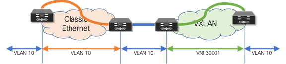
Figure 9 Consistent VLAN Mapping
As shown in the example below, the drawback of using the same VLAN mapping across all nodes is that even though VXLAN can support a significantly larger namespace, the number of Layer 2 identifiers possible across both networks stays at the available VLAN namespace.
VLAN mapping—Ingress Classic Ethernet node
vlan 10
VLAN mapping—Egress Classic Ethernet node
vlan 10
VLAN mapping—Ingress VXLAN node
vlan 10
vn-segment 30001
VLAN mapping—Egress VXLAN node
vlan 10
vn-segment 30001
Scenario 2: Mapping between Different VLANs
The second scenario provides a flexible mapping option for VLANs. From the first Classic Ethernet node (ingress), the VLAN stays consistent until it reaches the first VTEP (ingress). At this point, the VLAN is mapped to a VNI and transported across the overlay. At the destination VTEP (egress), the VNI is mapped to a different VLAN. (See Figure 10)
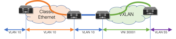
Figure 10 Flexible VLAN Mapping
In addition to the flexible VLAN Mapping, the port-VLAN translation approach in VXLAN can provide additional flexibility. This approach allows translation of the incoming VLAN from the brownfield (Classic Ethernet) so that the VXLAN environment will never learn of the originally used Classic Ethernet VLAN. (See Figure 11)
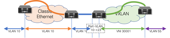
Figure 11 Flexible VLAN Mapping with Port-VLAN Translation
The drawback to this scenario resides in that VLANs change at various stages. While this method allows using VXLAN’s larger namespace, the translations and mapping at various stages can introduce operational complexity.
VLAN mapping—Ingress Classic Ethernet node
vlan 10
VLAN mapping—Egress Classic Ethernet node
vlan 10
VLAN mapping—Ingress VXLAN node (without port-VLAN)
vlan 10
vn-segment 30001
VLAN mapping—Ingress VXLAN node (with port-VLAN)
vlan 23
vn-segment 30001
interface port-channel 10
switchport vlan mapping enable
switchport vlan mapping 10 23
switchport trunk allowed vlan 23
VLAN mapping—Egress VXLAN node
vlan 55
vn-segment 30001
Layer 3 Interconnection
Interconnecting a brownfield network with a greenfield network via Layer 3 is crucial to allow communication between the endpoints in different IP subnets at various stages of the migration (Figures 12–13). The idea is to allow endpoints the ability to communicate with other endpoints in the same subnet or different subnets before, during, and after migration.
Note: Even when seamless workload migration is not required, a Layer 3 interconnect between brownfield and greenfield is necessary. However, the requirement for a direct interconnection can be relaxed, and external connectivity of the individual environments can be used for a per-subnet migration.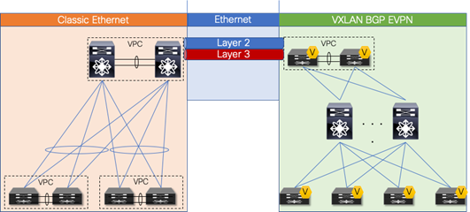
Figure 12 Overview: Brownfield-Greenfield Interconnection (Direct)
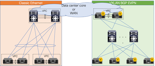
Figure 13 Overview: Brownfield-Greenfield Interconnection (Datacenter Core or WAN)
For the Layer 3 interconnection, establish a route peering session between a pair of nodes in the greenfield (VXLAN) and brownfield (Classic Ethernet) network respectively. During the migration from a Classic Ethernet network to a VXLAN BGP EVPN network, you interconnect the networks with a Virtual Route Forwarding (VRF)-aware approach, thereby using the multitenancy capability present in the greenfield VXLAN BGP EVPN network.
Note: Workloads or endpoints in the VXLAN BGP EVPN network are always present in a VRF instance other than VRF default or management.
As mentioned earlier, the nodes chosen in the greenfield network can represent a border node or any other switch that provides the VXLAN BGP EVPN tunnel endpoint functionality. In the brownfield network, the nodes for the interconnection should represent the Layer 2–Layer 3 demarcation. In Classic Ethernet, that demarcation is often found at the Aggregation nodes. The topology is referred to as Access/aggregation with first-hop gateway at aggregation using VPC and traditional FHRP (HSRP)
Note: This guide considers the Layer 2–Layer 3 interconnect to be separate connections, hence separate physical interfaces are used. In certain scenarios, the same physical connection can be employed for carrying Layer 2 and Layer 3 traffic with the use of the dynamic-routing-over-VPC feature. However, for this scenario, this feature must be supported on both the Classic Ethernet VPC as well as in the VXLAN BGP EVPN VPC environment.
Routing Protocol Choice
Several considerations must be considered when choosing routing protocols. Many or all may be viable for providing Layer 3 routing exchange between network nodes, but in the case of migration from a fabric network to a VXLAN BGP EVPN network, the following considerations are important in the context of this guide:
1. Greenfield network with VXLAN BGP EVPN
2. Clean routing domain separation
3. Extensive routing policy capability
4. VRF awareness
Given that BGP provides these capabilities and meets the requirements, we focus on the Layer 3 interconnection with external BGP (eBGP) as the routing protocol of choice.
Note: Other routing protocols can equally accommodate the requirement for the Layer 3 interconnect, but they might require additional redistribution configuration.
Note: By using VXLAN BGP EVPN in the greenfield network and eBGP for the Layer 3 interconnect, all host routes (/32 and /128) by default are advertised to the eBGP peers in the brownfield network. For migration, it might be beneficial to filter out these host routes to not overwhelm the available scale in the brownfield environment. Recall that in the brownfield environment, only non-host (/32 and /128) routing prefixes are advertised for reachability.
VRF Mapping
Note: By using VRF-lite for the Layer 3 interconnect between brownfield and greenfield networks, all existing best practices for VXLAN BGP EVPN and VRF-lite are applicable, even though some configurations may have been omitted for the sake of brevity.
Scenario 1: 1:1 Mapping between VRFs
The first scenario follows a consistent mapping where all the VRFs from the Classic Ethernet network are mapped to a matching VRF in the VXLAN BGP EVPN network. To accommodate this mapping, employ a VRF-lite approach by using subinterfaces and Layer 3 ECMP at the interconnect. The result is per-VRF eBGP peering at the Layer 2–Layer 3 demarcation node in the brownfield Classic Ethernet network and at the VXLAN BGP EVPN border node in the greenfield network. A point-to-point IP subnet per-VRF is employed, and the routing table between the two environments is exchanged. For the IP subnets in the Classic Ethernet network, ensure that the associated network prefixes are advertised into BGP. In the example in Figure 14, Switched Virtual Interface (SVI) 10 is instantiated on the VXLAN BGP EVPN network with distributed IP anycast gateway 192.168.10.1. The first-hop gateway for IP subnet 192.168.20.0/24 is instantiated on the brownfield Classic Ethernet network with HSRP. Routed traffic between these two subnets traverses the Layer 3 interconnect between the two networks.
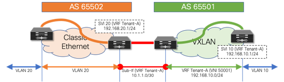
Figure 14 Consistent per-VRF Mapping
Layer 3 Configuration—Classic Ethernet Aggregation Node (named-to-named)
vlan 20
!
vrf context Tenant-A
!
interface vlan 20
vrf member Tenant-A
ip address 192.168.20.201/24
hsrp 10
ip 192.168.20.1
!
interface ethernet 1/10
no switchport
!
interface ethernet 1/10.20
encapsulation dot1q 20
vrf member Tenant-A
ip address 10.1.1.2/30
!
router bgp 65502
vrf Tenant-A
address-family ipv4 unicast
network 192.168.20.0/24
neighbor 10.1.1.1
remote-as 65501
update-source Ethernet1/10.20
address-family ipv4 unicast
Layer 3 Configuration—VXLAN BGP EVPN Border Node (named-to-named)
vlan 2001
vn-segment 50001
!
interface vlan 2001
vrf member Tenant-A
ip forward
no ip redirects
no shutdown
!
vrf context Tenant-A
vni 50001
rd auto
address-family ipv4 unicast
route-target both auto
route-target both auto evpn
!
interface nve 1
member vni 50001 associate-vrf
!
interface ethernet 1/10
no switchport
!
interface ethernet 1/10.20
encapsulation dot1q 20
vrf member Tenant-A
ip address 10.1.1.1/30
!
router bgp 65501
vrf Tenant-A
address-family ipv4 unicast
advertise l2vpn evpn
neighbor 10.1.1.2
remote-as 65502
update-source Ethernet1/10.20
address-family ipv4 unicast
Scenario 2: Mapping from Default VRF
The second scenario follows a many-to-one mapping where the VRF “default” in the Classic Ethernet network is mapped to a named VRF in the VXLAN BGP EVPN network (Figure 15). For this mapping, we employ a VRF-lite approach using the physical Interface in the brownfield and greenfield network. For redundancy and load sharing, Layer 3 ECMP is used at the interconnect. As a result, there is one eBGP peering in the VRF default (global routing table/underlay) at the Layer 2–Layer 3 demarcation node in the brownfield Classic Ethernet network, and a named VRF eBGP peering at the VXLAN BGP EVPN border node in the greenfield network. As before, a point-to-point IP subnet is used for peering, and the routing table between the two environments is exchanged. For each IP subnet in the Classic Ethernet network, we ensure that the associated network prefixes are respectively advertised into BGP.

Figure 15 VRF Default to VRF Tenant-A
Layer 3 Configuration—Classic Ethernet Aggregation Node (default-to-named)
vlan 20
!
interface vlan 20
ip address 192.168.20.201/24
hsrp 10
ip 192.168.20.1
!
interface ethernet 1/10
ip address 10.1.1.2/30
!
router bgp 65502
address-family ipv4 unicast
network 192.168.20.0/24
neighbor 10.1.1.1
remote-as 65501
update-source Ethernet1/10
address-family ipv4 unicast
Layer 3 Configuration—VXLAN BGP EVPN Border Node (default-to-named)
vlan 2001
vn-segment 50001
!
interface vlan 2001
vrf member Tenant-A
ip forward
no ip redirects
no shutdown
!
vrf context Tenant-A
vni 50001
rd auto
address-family ipv4 unicast
route-target both auto
route-target both auto evpn
!
interface nve 1
member vni 50001 associate-vrf
!
interface ethernet 1/10
no switchport
vrf member Tenant-A
ip address 10.1.1.1/30
!
router bgp 65501
vrf Tenant-A
address-family ipv4 unicast
advertise l2vpn evpn
neighbor 10.1.1.2
remote-as 65502
update-source Ethernet1/10
address-family ipv4 unicast
If it is necessary to allow the VXLAN BGP EVPN underlay to be reachable from the Classic Ethernet network, an extra eBGP peering session can be established from the brownfield VRF default to the greenfield VRF default (Figure 16). Because we require a routing session from the VXLAN BGP EVPN network in both the VRF default and VRF Tenant-A into the VRF default on the Classic Ethernet side, we either need two physical interfaces or use subinterfaces.
The example below shows how this can be achieved using subinterfaces. Note that while, as before, SVI 20 (HSRP) and SVI 20 (DAG) have been instantiated on the brownfield and greenfield networks, in this example, 10.10.10.0/24 is the underlay subnet on the greenfield VXLAN network that needs to be advertised over to the brownfield Classic Ethernet network.
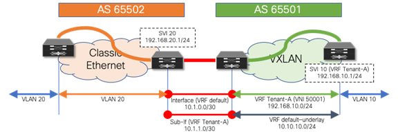
Figure 16 VRF Default to VRF Default and Tenant-A
Layer 3 Configuration—Classic Ethernet Aggregation Node (default-to-default/named
vlan 20
!
interface vlan 20
ip address 192.168.20.201/24
hsrp 10
ip 192.168.20.1
!
interface ethernet 1/10
no switchport
ip address 10.1.0.2/30
!
interface ethernet 1/10.20
encapsulation dot1q 20
ip address 10.1.1.2/30
!
router bgp 65502
address-family ipv4 unicast
network 192.168.20.0/24
neighbor 10.1.0.1
remote-as 65501
update-source Ethernet1/10
address-family ipv4 unicast
neighbor 10.1.1.1
remote-as 65501
update-source Ethernet1/10.20
address-family ipv4 unicast
Layer 3 Configuration—VXLAN BGP EVPN Border Node (default-to-default/named)
vlan 2001
vn-segment 50001
!
interface vlan 2001
vrf member Tenant-A
ip forward
no ip redirects
no shutdown
!
vrf context Tenant-A
vni 50001
rd auto
address-family ipv4 unicast
route-target both auto
route-target both auto evpn
!
interface nve 1
member vni 50001 associate-vrf
!
interface ethernet 1/10
no switchport
ip address 10.1.0.1/30
!
interface ethernet 1/10.20
encapsulation dot1q 20
vrf member Tenant-A
ip address 10.1.1.1/30
!
router bgp 65501
address-family ipv4 unicast
network 10.10.10.0/24
neighbor 10.1.0.2
remote-as 65502
update-source Ethernet1/10
address-family ipv4 unicast
vrf Tenant-A
address-family ipv4 unicast
advertise l2vpn evpn
neighbor 10.1.1.2
remote-as 65502
update-source Ethernet1/10.20
address-family ipv4 unicast
Default Gateway Migration Considerations (prior to NX-OS Release 10.2(3))
While interconnecting the brownfield network with the greenfield network is an important task, the placement of the first-hop gateway is equally important. During migration from a Classic Ethernet network to a VXLAN BGP EVPN network, when running pre-10.2(3) NX-OS software release, the first-hop gateway cannot simultaneously be active in both the brownfield and greenfield network, because the two first-hop gateways operate in different modes. While the brownfield operates in a traditional FHRP or anycast HSRP mode, the VXLAN BGP EVPN greenfield uses the distributed IP anycast gateway (DAG). These two different first-hop gateway modes are not compatible and cannot be active at the same time. The recommendation is, therefore, to upgrade to NX-OS Release 10.2(3) or later, to enable the coexistence of these first-hop gateway modes, as explained in Default Gateway Coexistence of HSRP and Anycast Gateway (VXLAN EVPN) (NX-OS Release 10.2(3) and later).
Note: The scenarios below are important when it is not possible or desired to activate this new functionality in NX-OS Release 10.2(3).
Scenario 1: Centralized First-Hop Gateway
Because migration starts from the brownfield network, the first-hop gateway used to establish communication between IP subnets is initially maintained there. This placement implies that the VXLAN BGP EVPN fabric initially provides only Layer 2 services, and the endpoints already migrated to the VXLAN BGP EVPN fabric send traffic to the brownfield network across the Layer 2 interconnect. Intersubnet or routed traffic from and to endpoints in the greenfield network, trombones over the Layer 2 interconnect to reach the first-hop gateway on the brownfield side, as shown in Figure 17.
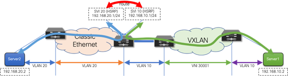
Figure 17 First-Hop Gateway in Brownfield Network
After all the workloads of a given IP subnet (VLAN) are migrated into the VXLAN BGP EVPN fabric, it is then possible to also migrate the first-hop gateway into the VXLAN BGP EVPN domain. This migration is performed by turning on DAG routing in the VLAN or VNI associated with the corresponding IP subnet and decommissioning the first-hop gateway function on the brownfield network devices (Figure 18). This way, the border nodes never need to have the distributed IP anycast gateway, assuming they have no directly attached workloads.
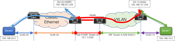
Figure 18 First-Hop Gateway in Brownfield and Greenfield Networks
First-Hop Configuration—Classic Ethernet Aggregation Node
vlan 20
!
vrf context Tenant-A
!
interface vlan 20
vrf member Tenant-A
ip address 192.168.20.201/24
hsrp 10
ip 192.168.20.1
!
First-Hop Configuration—VXLAN BGP EVPN Leaf Node
fabric forwarding anycast-gateway-mac 2020.0000.00aa
!
vlan 10
vn-segment 30001
!
vrf context Tenant-A
vni 50001
rd auto
address-family ipv4 unicast
route-target both auto
route-target both auto evpn
!
interface vlan 10
vrf member Tenant-A
ip address 192.168.10.1/24
fabric forwarding mode anycast-gateway
Scenario 2: Anycast First-Hop Gateway
In the second scenario, the first-hop gateway is immediately migrated from the brownfield network to the greenfield network before the workload migration begins (Figure 19). In this approach, no change to the migration infrastructure is required once migration begins. In contrast to the first scenario, there is a centralized first-hop gateway and later move the function to a DAG once all endpoints in that associated subnet are migrated. Here we move to the DAG first and maintain that state during the lifecycle of the network. Note that in this scenario, the DAG is also instantiated at the border nodes. This serves as the first-hop gateway for the workloads in the brownfield environment. As workloads move over to the VXLAN BGP EVPN network, their directly attached leaf takes over the first-hop gateway functionality.
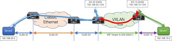
Figure 19 First-Hop Gateway Greenfield Network Only
First-Hop Configuration—VXLAN BGP EVPN Nodes
fabric forwarding anycast-gateway-mac 2020.0000.00aa
!
vlan 10
vn-segment 30001
!
vlan 20
vn-segment 30002
!
vrf context Tenant-A
vni 50001
rd auto
address-family ipv4 unicast
route-target both auto
route-target both auto evpn
!
interface vlan 10
vrf member Tenant-A
ip address 192.168.10.1/24
fabric forwarding mode anycast-gateway
!
interface vlan 20
vrf member Tenant-A
ip address 192.168.20.1/24
fabric forwarding mode anycast-gateway
Although neither first-hop gateway migration approach is preferred, each approach has its advantages and disadvantages. The second scenario has in its favor the fact that the DAG is used early, thereby providing experience in using it before migrating the major workloads. On the other hand, scenario 2 also has the disadvantage that, until the workload migration begins, traffic will always trombone over the Layer 2 interconnect.
Regardless of the chosen scenario, the preparatory steps required before the migration begins are similar.
Premigration Preparation — First-Hop Gateway
For the first-hop gateway migration, make sure that the change is as seamless as possible for the endpoints. The endpoints are typically configured with a default gateway IP to reach any destination outside their local IP subnet. The default gateway IP-to-MAC binding at the endpoint is resolved via the Address Resolution Protocol (ARP). Although it is easy to align the IP addresses from FHRP to the DAG, the alignment of the virtual MAC address to the anycast gateway MAC requires additional considerations.
With HSRP, the virtual MAC address for the first-hop gateway is derived from the HSRP version (1 or 2) and the configured HSRP group. It is commonly seen that HSRP groups change on a per-VLAN or per-SVI basis. The DAG used in VXLAN BGP EVPN follows a different approach from the per-group virtual MAC employed by HSRP. For the DAG, a global anycast gateway MAC is defined. This means that the virtual MAC—or more accurately the anycast gateway MAC—is the same for all first-hop gateways on the given node. In fact, the same anycast gateway MAC is shared by all the nodes in a given fabric.
Clearly, with these different approaches for virtual MAC assignments, some mechanism is needed to align the virtual MACs to allow migration from the HSRP MAC to the anycast gateway MAC.
As the endpoints are part of the brownfield network, they store the default gateway IP–to–HSRP virtual MAC binding in their ARP cache. Eventually, when the DAG is enabled, the ARP cache of the endpoints should be updated to have the gateway IP mapped to the anycast gateway MAC. Clearly, manually updating the ARP cache of every endpoint is tedious and impractical. Hence, in the brownfield network, even before starting the migration, the HSRP virtual MAC address for each VLAN or subnet should be updated to be the same as the anycast gateway MAC, via a configuration update, as shown here:
HSRP Virtual MAC Configuration—Classic Ethernet Aggregation Nodes
interface vlan 20
vrf member Tenant-A
ip address 192.168.20.201/24
hsrp 10
ip 192.168.20.1
mac-address 2020.0000.00aa
Anycast Gateway MAC Configuration—VXLAN BGP EVPN Nodes
fabric forwarding anycast-gateway-mac 2020.0000.00aa
After the change from the HSRP group-based virtual MAC address on the brownfield network side (Classic Ethernet) to the anycast gateway MAC, we must ensure that all endpoints learn about that change. Changing the state of FHRP from active to standby enables the first-hop gateway instance to send out a gratuitous ARP (GARP) message to inform all endpoints about the updated IP-to-MAC binding. As a result of this state change and GARP, the endpoints either update their ARP cache or invalidate their ARP cache and trigger an ARP request for the first-hop gateway’s MAC address. As a result, the new virtual MAC address (anycast gateway MAC) for the first-hop gateway is learned at the endpoints.
Note: The practice of changing the FHRP virtual MAC followed by a state change (active-standby) results in the highest probability that connected endpoints relearn the first-hop gateway’s new virtual MAC address. Nonetheless, a possibility remains that some endpoints will not honor the signalization through GARP or have a static MAC entry for the first-hop gateway. These endpoints require manual intervention to flush their ARP cache and hence, we recommend performing this action during a Maintenance Window.
After the premigration steps for the first-hop gateway are complete, the migration of workloads can be performed seamlessly. At the time, when the old first-hop gateway (HSRP) has to be disabled and the new first-hop gateway (DAG) enabled, a small traffic disruption may be observed. Hence, we recommend performing such first-hop gateway changes during a maintenance window. We reiterate that, for a given IP subnet or VLAN, FHRP in the brownfield network and the DAG in the greenfield network should never be enabled at the same time. Otherwise, unexpected forwarding behavior, ARP table misprogramming, and traffic forwarding failure can result.
Before describing more in detail how this new approach works, it is important to clarify a couple of points:
1. The configuration steps described in the previous “Premigration preparation—First-hop gateway” are still required to align the default gateway virtual MAC addresses in the Classic Ethernet network and VXLAN EVPN fabric.
2. The same recommendation of performing those pre-migration steps during a maintenance window continue to apply, just to handle the scenarios where the endpoints do not update their ARP caches based on received GARP messages and manual intervention is required for that purpose.
Refer to the following URL for detailed guidelines and deployment considerations for this new functionality:
In order to understand why this innovation was required to enable seamless coexistence of HSRP and DAG modes, let’s give a look at what would happen with pre-10.2(3) software when two subnets are extended between the Classic Ethernet network and the VXLAN EVPN fabric and an endpoint EP1 in the fabric belonging to subnet 10 was trying to communicate with an endpoint EP2 in the legacy network belonging to subnet 20 (figure 20).
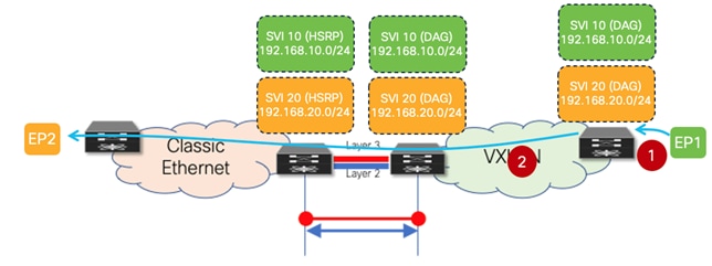
Figure 20 ARP Request Between VXLAN EVPN Fabric and Classic Ethernet Network
1. EP1, after completing the ARP exchange to resolve the VMAC of the DAG deployed on the leaf where it connects, sends a data packet destined to the VMAC of the DAG (Layer 2 header) and to EP2’s IP address (Layer 3 header).
2. The VXLAN EVPN leaf node routes the packet and, assuming EP2’s MAC/IP information has not been discovered in the fabric yet, generates an ARP request targeted to EP2. This packet is a Layer 2 broadcast packet, and it is flooded inside the fabric and on the Layer 2 connection between the two networks, until it reaches EP2. It is worth noticing how the payload of this ARP request contains the DAG VMAC and DAG IP as Sender MAC and IP addresses.
The figure below highlights the problem when EP2 replies to the ARP request.
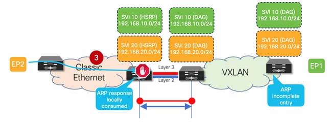
Figure 21 ARP Reply Locally Consumed on the HSRP Gateways on the Classic Ethernet Network
3. EP2 replies to the ARP request with a unicast ARP reply destined to the DAG VMAC (the Sender MAC of the received ARP request) and containing the DAG VMAC and DAG IP in the payload. Since the same VMAC and IP addresses have been configured on the HSRP gateways (as part of the pre-requisite configuration steps previously described), the ARP reply is locally consumed by the legacy aggregation device that receives it and it never reaches the VXLAN EVPN fabric. This implies that EP2’s MAC and IP addresses are never learned in the VXLAN EVPN fabric. Also, the leaf node that generated the ARP request for EP2 never gets the ARP reply and displays an ARP incomplete entry for EP2’s IP address.
The following two figures show instead the same communication pattern once the new functionality available in NX-OS Release 10.2(3) (and later) is enabled.
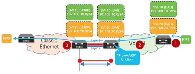
Figure 22 Proxy-ARP Function Enabled on the VXLAN EVPN Border Leaf Node
1. EP1, after completing the ARP exchange to resolve the VMAC of the DAG deployed on the leaf where it connects, sends a data packet destined to the VMAC of the DAG (Layer 2 header) and to EP2’s IP address (Layer 3 header).
2. The VXLAN EVPN leaf node routes the packet and, assuming EP2’s MAC/IP information has not been discovered in the fabric yet, generates an ARP request targeted to EP2. This packet is a Layer 2 broadcast packet, and it is flooded inside the fabric reaching the border leaf node(s) connected to the Classic Ethernet network. It is worth noticing how the payload of this ARP request contains the DAG VMAC and DAG IP as Sender MAC and IP addresses.
3. A “Proxy-ARP” function is now performed on the border leaf node, allowing to change the payload of the ARP request before forwarding it toward the Classic Ethernet network. Specifically, the border leaf system MAC is replacing the DAG VMAC as Sender MAC, whereas a border leaf specific IP address (configured as a secondary IP address on the SVI associated to the subnet for which the ARP is sent) is replacing the DAG IP as Sender IP.
Because of those changes applied on the border leaf node to the payload of the original ARP request, the forwarding of the ARP unicast reply from EP2 now changes as shown in the figure below.
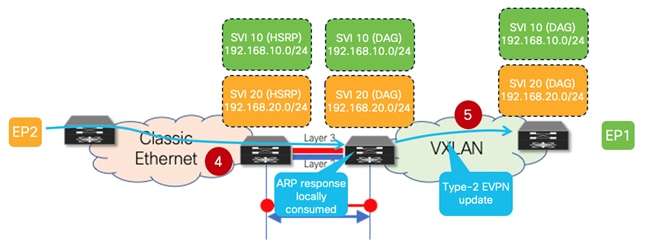
Figure 23 EP2’s ARP Reply Reaching the VXLAN EVPN Fabric
4. EP2 replies to the ARP request with a unicast ARP reply destined to the border leaf system MAC (the Sender MAC of the received ARP request). The packet is hence forwarded by the aggregation switches on the Layer 2 connection toward the VXLAN EVPN fabric and reaches the border leaf node that generated the “Proxy-ARP” request. The border leaf locally consumes the ARP reply and learns from it EP2’s MAC and IP information. From the point of view of the VXLAN EVPN fabric, EP2 is seen as an endpoint directly connected to the border leaf node.
5. The border leaf generates a Type-2 MP-BGP EVPN update and forwards it inside the fabric. This enables the leaf node where EP1 is connected to start routing traffic toward EP2 via the border leaf node (i.e., the leaf is not trying anymore to ARP for the destination).
Based on what has been explained above, it should be clear how the “Proxy-ARP” function enabled on the VXLAN EVPN border leaf nodes is the critical functionality allowing the coexistence of DAG and HSRP gateway modes. The configuration required to enable such functionality on the border leaf nodes is quite simple, as only two specific commands are required:
◦ The first one consists in configuring a secondary IP address associated to each DAG SVIs deployed on that node. This is a unique IP address assigned to each border leaf node that is inserted as Sender IP in the payload of the Proxy-ARP request. As such, sometimes this IP address is also referred to as the “external” IP address of the border node’s SVI.
interface vlan 10
vrf member Tenant-A
ip address 192.168.10.1/24
ip address 192.168.10.10 secondary use-bia
fabric forwarding mode anycast-gateway
!
interface vlan 20
vrf member Tenant-A
ip address 192.168.20.1/24
ip address 192.168.20.10 secondary use-bia
fabric forwarding mode anycast-gateway
Note: While the above configuration focuses on IPv4 configuration, the same functionality is supported for IPv6 deployments also.
◦ The second one allows identifying the specific interface where to start performing the “Proxy-ARP” function, which is the Layer 2 connection toward the Classic Ethernet network.
interface port-channel1
description vPC to the Classical Ethernet network
switchport
switchport mode trunk
switchport trunk allowed vlan 10.20
port-type external
vpc 1
The following are important and final considerations:
1. The requirement to enable the “Proxy-ARP” function only applies to the border leaf nodes to handle to modify the payload of ARP requests originated inside the VXLAN EVPN fabric and destined to endpoints connected to the Classic Ethernet network. For ARP requests originated by the aggregation devices in the Classic Ethernet network and destined to endpoints connected to the VXLAN fabric, there is no need to modify the ARP payload as the aggregation switches by default always use their unique SVI IP and switch MAC addresses as Sender MAC and IP values. This ensures that ARP responses are always returned to the specific aggregation node that generated the ARP request.
2. An endpoint originating an ARP request for its default gateway will always receive a single ARP response, independently from where the endpoint is connected.
◦ If the endpoint is part of the legacy environment, the ARP response will only come from the FHRP active node. This is because even if the original ARP request will be flooded toward the VXLAN EVPN fabric, it will be dropped when received on the "external" interface of the border nodes.
◦ If the endpoint is part of the VXLAN EVPN fabric, the ARP response will be received by the directly connected leaf node. ARP requests received on the fabric-facing ports of the border leaf nodes are dropped and never forwarded toward the Classic Ethernet network.
Migration Walkthrough
The preceding sections details the different aspects of migrating a brownfield Classic Ethernet network to a greenfield VXLAN BGP EVPN network. Although the individual steps have been explained, we have not yet described the migration process in chronological order. This section summarizes the main steps of the migration.
Locating Interconnection Nodes in Brownfield and Greenfield Network
It is important to define the location of where the Layer 2 to Layer 3 demarcation exists in the brownfield network (Figure 24). In the greenfield network, the interconnection point can be at any border node or similar node that can serve the routing and bridging requirements.

Figure 24 Interconnection Location
Building a Layer 3 Interconnect
The Layer 3 interconnect or Layer 3 external connectivity must exist in the brownfield and greenfield network (Figure 25). Ensure that the IP subnet and associated prefix local to each of the respective environments are advertised and learned in the adjacent network.
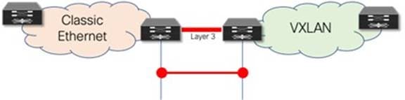
Figure 25 Layer 3 Interconnect
Building a Layer 2 Interconnect
The Layer 2 Interconnect is necessary if only seamless workload mobility and first-hop gateway sharing are required (Figure 26).
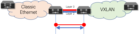
Figure 26 Layer 2 Interconnect
Defining the First-Hop Gateway Approach
The choice of first-hop gateway approach is dependent on the specific NX-OS release,
· Before NX-OS Release 10.2(3), it is necessary to decide if the brownfield network provides the first-hop gateway during the migration (Scenario 1) or if the greenfield network takes over this function as soon as possible (Scenario 2). Two different first-hop gateway modes (HSRP and DAG) cannot be simultaneously enabled for the same IP subnet. Only one first-hop gateway mode at a time must be enabled, with the goal being to migrate to the DAG at the end of the migration. Figure 27 represents Scenario 1, where the first-hop gateway is kept on the Classic Ethernet side until the migration of the endpoints part of that subnet is completed.
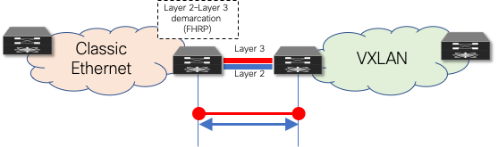
Figure 27 Layer 2–Layer 3 Demarcation (FHRP) as First-Hop Gateway
· From NX-OS Release 10.2(3), seamless coexistence of HSRP and Anycast Gateway modes is supported, and this allows to keep the two first-hop gateway modes simultaneously enabled for the same IP subnet (see Figure 28).
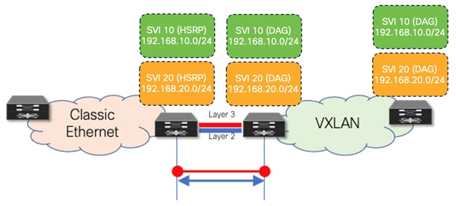
Figure 28 Coexistence of HSRP and DAG Gateway Modes
Aligning First-Hop Gateway Information (virtual MAC and virtual IP)
To facilitate seamless migration of the first-hop gateway, the virtual MAC and first-hop gateway IP address must be aligned first. To ensure that all endpoints learn the new virtual MAC (specifically the anycast gateway MAC) for the first-hop gateway, a state change must be performed on the FHRP-based first-hop gateway in the brownfield network.
Performing Workload Migration
After the interconnection at Layer 2 and Layer 3 is ready and the first-hop gateway has been respectively aligned, workloads can be migrated between the brownfield and the greenfield networks (Figure 29). This can be performed by using virtual machine mobility (cold or hot move) or by physically recabling workloads to the greenfield network. Also, the workload migration can be done independently from the fact that HSRP and DAG modes are simultaneously enabled or not.
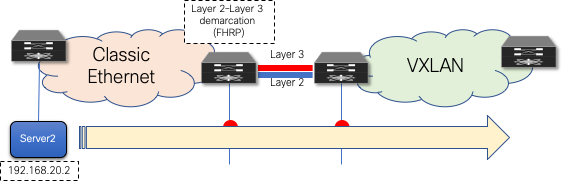
Figure 29 Workload Migration
Migrate and Decommission Unnecessary First-Hop Gateway
After the workloads have been migrated, the brownfield first-hop gateway can be decommissioned (Figure 30) and the greenfield first-hop gateway activated (Scenario 1) or simply kept enabled when leveraging the new functionality enabling the coexistence of HSRP and DAG modes. The decommissioning is not necessary with Scenario 2, where the DAG is enabled on the greenfield network before the workload migration begins.
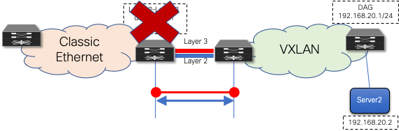
Figure 30 Decommission First-Hop Gateway
Decommission Layer 2 Interconnect
Although the Layer 3 external connectivity or interconnect might remain necessary for the lifecycle of the remaining resources in the brownfield network, the Layer 2 interconnect for the first-hop gateway can be decommissioned once the workload migration is complete. It is a good practice not to have any Layer 2 interconnects if they are not required, to avoid any possibility of Layer 2 loops (Figure 31).
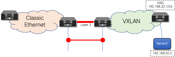
Figure 31 Decommission Layer 2 Interconnect
Cisco Nexus Dashboard Fabric Controller
Note: Cisco Data Center Network Manager (DCNM) is renamed as Cisco Nexus Dashboard Fabric Controller (NDFC) from Release 12.0.1a.
Using Cisco Nexus Dashboard Fabric Controller for Migration with Classic LAN Fabric Type
Among the many capabilities of Cisco Nexus Dashboard Fabric Controller software, perhaps the most appealing is its ability to manage multiple network deployments across the Cisco Nexus family of switches. The fabric controller instance can manage legacy 3-tier access-aggregation-core deployments, FabricPath deployments, routed fabrics, and VXLAN BGP EVPN deployments. On top of that, NDFC has the capability to manage brownfield and greenfield networks (Figure 32). NDFC supports Day-0 network provisioning using a flexible, customizable bootstrap workflow for device onboarding, Day-1 provisioning using configuration templates or profiles, and Day-2 network performance monitoring and troubleshooting. A Configuration Compliance engine closes the operations loop by periodically checking the NDFC-defined intent against what is configured on the switch. Any deviation is detected, flagged, and an appropriate remediation action is provided to bring back the switch IN-SYNC. NDFC groups switches that belong to a given network deployment into what are called fabrics. For more information on Day-0/Day-1/Day-2 VXLAN EVPN–based LAN provisioning, refer to Cisco NDFC Fabric Controller Configuration Guide.
Classic LAN fabric type is available since NDFC 12.0 release to manage classic hierarchical networks with Nexus platforms ranging from Nexus 2000, 5000, 6000, 7000, 9000 series. However, with Classic LAN fabric, the switch policies need to be manually applied and there is no support for brownfield import. It only supports interface level brownfield using the host port resync feature. To address the limitations with Classic LAN, Cisco introduces the Enhanced Classic LAN fabric type with NDFC 12.1(3) release. To understand more about Enhanced Classic LAN, see the further sections in this document.
Figure 32 to Figure 34 shows Classic LAN and the VXLAN BGP EVPN fabric types supported on NDFC, and their interconnections required for migration or co-existence.
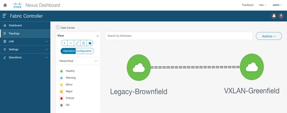
Figure 32 Cisco NDFC Managing Brownfield and Greenfield Deployments
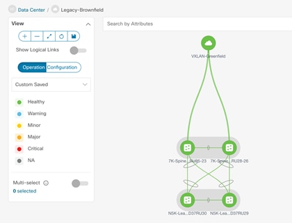
Figure 33 Cisco NDFC Managing Brownfield Classic Ethernet Network using Classic LAN Fabric
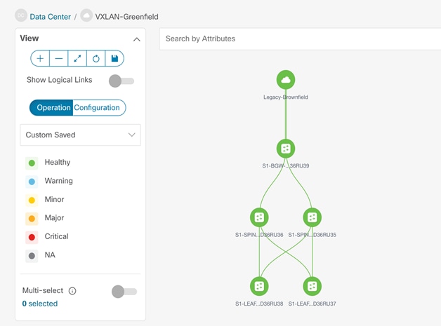
Figure 34 Cisco NDFC Managing Greenfield VXLAN BGP EVPN Fabric
When migrating a brownfield Classic Ethernet network to a greenfield VXLAN BGP EVPN fabric, the Cisco Nexus Dashboard Fabric Controller can support in the following ways:
1. Importing and discovering existing brownfield Classic Ethernet network - NDFC will import switches while preserving all their configurations. The switches can thereafter be managed incrementally from NDFC. You must do an explicit ‘Host Port Resync’ for NDFC to learn the interface configurations. Any other global configurations need to be manually ported to NDFC using policies.
2. Setting up the greenfield VXLAN BGP EVPN fabric through POAP/bootstrap/switch IP discovery.
3. Setting up the Layer 3 interconnect between the greenfield VXLAN BGP EVPN fabric and the brownfield Classic Ethernet network.
4. Setting up the VPC connection between the brownfield Classic Ethernet network and the greenfield VXLAN BGP EVPN fabric (Layer 2 interconnect).
5. Migrating the first-hop gateway from the brownfield network to the greenfield fabric (pre NX-OS 10.2(3)). As mentioned in this document, this step is required with switches running NX-OS software releases antecedent to 10.2(3).
6. Seamless co-existence of FHRP and anycast gateway modes from NXOS 10.2(3) and later using freeform templates in NDFC.
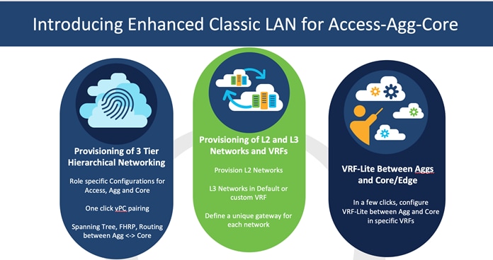
Using NDFC for Migration with Enhanced Classic LAN Fabric Type
NDFC 12.1(3) release introduces a new fabric template called Enhanced Classic LAN. This template is introduced to completely automate the L2 and L3 aspects of Access – Aggregation – Core Classic LAN networks, as per Cisco best practice templates. This minimizes the learning curve and makes it easy to move to an SDN-driven approach, while preparing for the future by improving scalability, creating the opportunity to build overlays with VXLAN, and offering a wide variety of maintenance and operational features. This fabric type is supported only for Nexus 2000, 7000 and 9000 platforms and allows to perform a full brownfield import, unlike the Classic LAN fabric type that represents the legacy way of managing CE networks.
For more details on Enhanced Classic LAN, see the Whitepaper.
Figure 35 depicts a typical example of Enhanced Classic LAN topology.
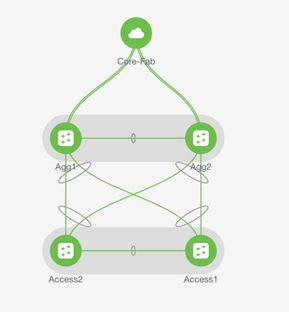
Figure 35 Enhanced Classic LAN Example Topology
When planning the migration between a legacy network and a greenfield VXLAN EVPN fabric leveraging the Enhanced Classic LAN fabric, there are two topologies that can be considered as shown in Figure 36 and Figure 37.
The approach depicted in Figure 36 is viable if the legacy network and the new VXLAN fabric are geographically co-located and can be directly connected with local point-to-point links.
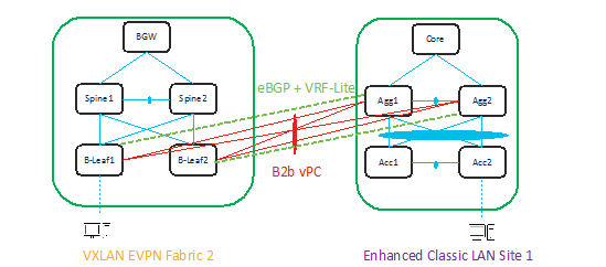
Figure 36 L2 and L3 connectivity between Aggregations in Brownfield Enhanced Classic LAN and Border Leaf in Greenfield VXLAN Fabric
The approach depicted in the Figure 37 is viable if the legacy network and the new VXLAN EVPN fabric are geographically dispersed. The use of Cisco BGWs is in this case required to extend connectivity between the two networks.
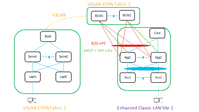
Figure 37 L2 and L3 Connectivity between Aggregation Switches in Enhanced Classic LAN and Border Gateway in VXLAN Fabric that Extends to Border Gateways in Greenfield VXLAN Fabric
In both the topologies shown above, it is required to establish Layer-2 and Layer-3 connectivity between the two networks. This is done on NDFC in a slightly different way depending on the specific use case under consideration, but mandates that Enhanced Classic LAN and VXLAN EVPN fabric types are allowed to be configured within the same NDFC instance, until the Classic network is ready to be retired.
In the first scenario, the Aggregation layer devices in the brownfield site and the Border Leaf nodes of the VXLAN fabric are directly connected. This implies that Layer-2 connectivity (through vPC or Port-Channel connections) and L3 connectivity (configuring VRF-Lite on separate dedicated interfaces) can be provisioned using policies in NDFC. For more information, see Configuring vPC and Configuring VRF-Lite.
In the second use case, where the two networks are geographically dispersed, it is necessary that the Enhanced Classic LAN (ECL) network becomes a part of the same VXLAN EVPN Multi-Site Domain along with the VXLAN EVPN fabric. This approach, as shown in Figure 38, leverages VXLAN EVPN Multi-Site for establishing DCI connectivity between these networks for either co-existence or migration purposes.
For more information about VXLAN EVPN Multi-Site architecture, see the “Multi-Site Domain for VXLAN BGP EVPN Fabrics” chapter in the Cisco NDFC Fabric Controller Configuration Guide.
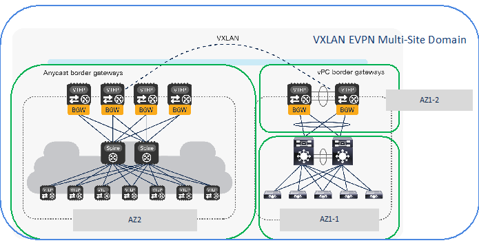
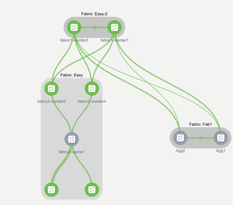
Figure 38 All Fabrics that are Part of the Same VXLAN EVPN Multi-Site Domain in a Geographically Dispersed Network
As shown in the figure above, the following fabric types must be defined in NDFC to provision connectivity between the legacy network and the greenfield VXLAN EVPN fabric:
1. An Enhanced Classic LAN fabric type is used for provisioning the Access-Aggregation-Core network, representing the first Availability Zone in Site 1 (AZ1-1).
2. A Datacenter VXLAN EVPN fabric type must also be defined representing a second Availability Zone in Site 1 (AZ1-2) for hosting the vPC Border Gateway (BGW) nodes locally connecting to the Aggregation switches in AZ1-1. The vPC BGW nodes are also required to extend Layer-2 and Layer-3 connectivity toward the VXLAN EVPN fabric in Site 2. They basically function simultaneously as leaf, border leaf and border gateway nodes.
3. A Datacenter VXLAN EVPN fabric type can finally be used for the Greenfield VXLAN Fabric in Site 2 consisting of Leaf-Spine-Border Gateway nodes (AZ2).
Note: In scenarios where multiple Enhanced Classic LAN fabrics (access/aggregation building blocks) are attached to the same pair of vPC BGW nodes in AZ1-2, you must ensure to use unique VLANs between the different vPC pairs of aggregation switches and the vPC BGW nodes.
Adding all the 3 fabrics in the same VXLAN EVPN multi-site domain allows to automate the extension of networks and VRFs between Border Gateways in AZ1-2 (Site 1) and Border Gateways in greenfield VXLAN Fabric AZ2 (Site 2).
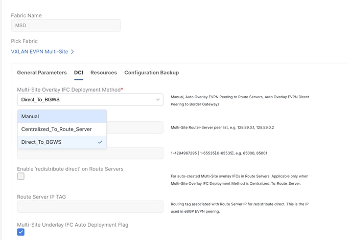
As seen below, for VXLAN EVPN Multi-Site Domain, you must set the IFC method to ‘Direct_to_BGWs’ or ‘Centralized_to_Route_Server’.
You can use NDFC for:
● Importing and discovering existing brownfield classic ethernet networks using the Enhanced Classic LAN fabric type
● Setting up the greenfield VXLAN BGP EVPN fabric
● Provision the required VXLAN EVPN Multi-Site configuration for layer-2 and layer-3 extension of networks between Classic and VXLAN fabrics
Enhanced Classic LAN uses the centralized default gateway concept with FHRP, whereas VXLAN uses a distributed anycast gateway (DAG) concept. For the co-existence of two disparate types of gateways, Cisco NX-OS introduced a new feature called “Proxy-ARP” starting from NX-OS release 10.2(3), as described in the "Default Gateway Coexistence of HSRP and Anycast Gateway (VXLAN EVPN)" chapter of the Cisco Nexus 9000 Series NX-OS VXLAN Configuration Guide. If the switches are running NX-OS 10.2(3) release or later, both DAG and FHRP gateways can co-exist and NDFC can be used to provision the same. For NX-OS releases prior to 10.2(3), only one kind of Gateway can be active at the same time. Hence, you must bring down the gateway for workloads from brownfield Enhanced Classic LAN network and move it to the greenfield VXLAN fabric with anycast gateway. Both these options are discussed in the following section.
Note: Non-disruptive migration is not supported if the existing Classic LAN fabric is using VRRP/VRRPv3 as FHRP protocol. In this case, you must schedule a maintenance window for migrating the default gateway between the legacy network and the greenfield VXLAN EVPN fabric.
To make the default gateway migration seamless, the FHRP virtual MAC used for each subnet in the Enhanced Classic LAN network must be aligned with anycast gateway MAC as defined in the fabric settings of Data Center VXLAN EVPN fabric. This is because while a single anycast gateway MAC is defined for all the subnets in a VXLAN EVPN fabric, the FHRP virtual MAC associated with each subnet depends on the specific FHRP group defined for that subnet. This implies that different FHRP group values are associated with different FHRP virtual MACs.
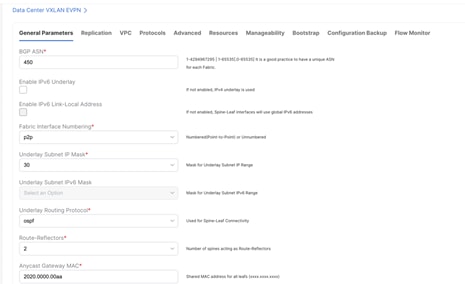
Figure 39 Anycast Gateway MAC in Data Center VXLAN EVPN Fabric Settings under General Parameters Tab
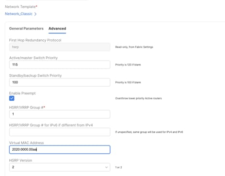
Figure 40 Virtual MAC address per Network (Under Advanced tab) in Enhanced Classic LAN Fabric Aligning with VXLAN Anycast Gateway MAC
Performing Migration using NDFC for NX-OS Release NXOS 10.2(3) and earlier
Note: We recommend that you schedule the migration during a maintenance window.
Before NX-OS Release 10.2(3), it was necessary to decide if the brownfield network provides the first-hop gateway during the migration (scenario 1) or if the greenfield network takes over this function as soon as possible (Scenario 2). Two different first-hop gateway modes (HSRP and DAG) cannot be simultaneously enabled for the same IP subnet. Only one first-hop gateway mode at a time must be enabled, with the intent of migrating to the DAG at some point during the migration.
The following migration scenario is applicable for geographically co-located Classic LAN and VXLAN fabrics as shown in Figure 36.
After the greenfield VXLAN EVPN fabric is provisioned through the NDFC Fabric Builder workflow, the VXLAN BGP EVPN overlay configuration can be instantiated on Cisco Nexus switches through a top-down push mechanism using Configuration Profile or CLI templates (Figure 35). Once the Layer 2–Layer 3 interconnect has been established and the premigration steps are complete, VXLAN overlay top-down provisioning can be initiated to push the appropriate Layer 2 configuration to the switches. By selecting the “Layer 2” option for a network, initially only the Layer 2 configuration of the associated network will be deployed to the switches.
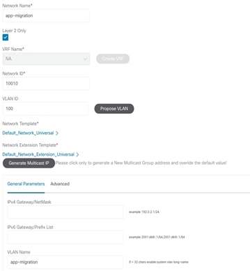
Figure 41 Deploying VXLAN Network (L2-only) on Leaf Switches
Figure 36 shows the preview screen for the configuration that is pushed down to the selected VXLAN BGP EVPN leaf switches.
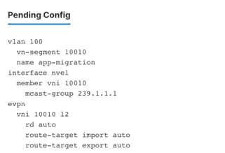
Figure 42 Preview of the VXLAN Configuration
Now, you can start deploying new workloads in these networks below the VXLAN EVPN fabric. In addition, existing workloads that are still connected to the legacy network can also be migrated over to the VXLAN EVPN fabric. All routed traffic from or to the workloads in the VXLAN EVPN fabric will still be forwarded through the centralized gateway on the Classic Ethernet network side.
Separately, the VRF can be deployed prior to the leaf or border switches on the VXLAN EVPN fabric to keep the switches prepared, in advance. Once all the endpoints for a given network or IP subnet is migrated from the brownfield network to the greenfield network, you should decommission the first-hop gateway on the brownfield Classic Ethernet network and to enable the Distributed IP Anycast Gateway functionality on the greenfield VXLAN BGP EVPN network (Figure 37). Essentially the Gateway IP with the appropriate network mask, can be filled in with the default gateway information for that subnet/network.
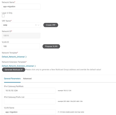
Figure 43 Uncheck Layer 2 Only Flag (Enabling Layer-3 GW) to Redeploy the Network
The change on the first-hop gateway can be performed using a script-based approach that shuts the FHRP-based first-hop gateway in the Brownfield Network or removes the FHRP configuration for that IP subnet. In addition, once this step is complete, the DAG is pushed down to the switches on the Greenfield Fabric. Figure 38 depicts the configuration that will be pushed to all switches on the VXLAN EVPN side. Both these tasks can be performed through the NDFC REST APIs that can trigger a configuration template job (for the brownfield network task) and the Network Manager top-down fabric provisioning for the greenfield fabric. As a result, the DAG becomes the first-hop gateway for the entire greenfield fabric.
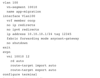
Figure 44 Preview of Distributed Anycast Gateway Configuration
Below migration scenario applies to geographically dispersed Classic and VXLAN fabrics as seen in Figure 38.
When geographically dispersed, Classic LAN as well as VXLAN fabrics are part of Multi-Site Domain. Once Enhanced Classic LAN is part of the VXLAN EVPN Multi-Site Domain, any net new networks and VRFs are still provisioned from the Enhanced Classic LAN fabric. Workflows of the creation of networks and VRFs in Classic LAN are covered in “Day 1 for Classic LAN” section of the White Paper. No action is required for the existing networks on Classic LAN.
For the VXLAN fabrics however, the workflows for networks and VRFs must be executed from VXLAN EVPN Multi-Site Domain and not individually within the VXLAN fabric. By doing so, the overlays can be pushed down to respective Border Gateways and Leaf nodes all at once. For migration, it is recommended to deploy these to the Border Gateways as well as the leaf nodes where the workloads are attached in VXLAN fabric.
Below is the initial state where the networks are deployed in Enhanced Classic LAN on Access and Aggregation.
Following is the final picture for the migration to be complete. Where the networks are deployed on the Border Gateways as well as the leaf nodes in the VXLAN fabric.
Consider the following 3 scenarios for mapping the networks and VRFs in Enhanced Classic LAN to overlays in VXLAN EVPN for migration use case. Ensure that you use the same VLAN for Enhanced Classic LAN and VXLAN networks.
1. L2 network: VLAN associated with a host in Classic LAN is mapped to an L2 network (Figure 45) in Enhanced Classic LAN. This network is deployed on Access switches where the hosts are attached. L2 Network in VXLAN EVPN Multi-Site Domain comprising of VXLAN EVPN fabrics as well as BGW sites must have matching VLAN as Classic LAN. VNIs for VXLAN will be auto allocated (Figure 46). This network can now be deployed to Border Gateways and Leaf nodes in a VXLAN network
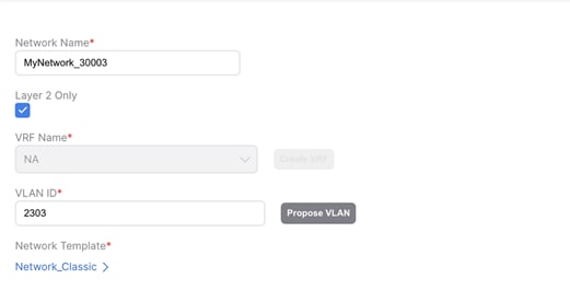
Figure 45 L2 Network in Enhanced Classic LAN
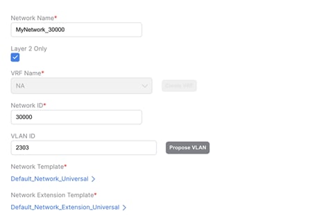
Figure 46 L2 Network in VXLAN EVPN Multi-Site Domain with the same VLAN ID as Enhanced Classic LAN
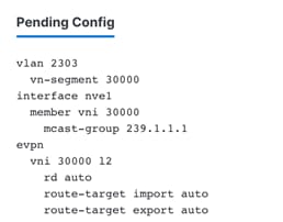
Figure 47 Pending Configuration for L2 Networks for VXLAN
2. L3 network in default VRF: An L3 network can be in a default or custom VRF. In this scenario, let’s discuss L3 network in a default VRF in Enhanced Classic LAN (Figure 48) where Aggregations are the FHRP gateway for these networks. These networks are deployed to Access switches with the hosts attached.
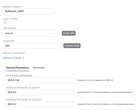
Figure 48 L3 Network in Default VRF in Enhanced Classic LAN with Gateway being the Aggregation Switches
Once all the endpoints for a given network/IP subnet have been migrated from the brownfield Enhanced Classic LAN network to the greenfield VXLAN network, you can decommission the first-hop gateway on the Classic Ethernet network and enable the Distributed IP Anycast Gateway functionality on the greenfield VXLAN BGP EVPN network. Essentially the gateway IP with the appropriate network mask, can be filled in with the default gateway information for that subnet or network (Figure 50).
Default VRF exists in Enhanced Classic LAN but is not a concept in VXLAN. Hence, a dummy VRF in VXLAN EVPN Multi-Site Domain must be created, analogous to this default VRF (Figure 49).
All L3 networks that are part of default VRF in Enhanced Classic LAN must be mapped to this dummy default VRF in VXLAN EVPN Multi-Site Domain (Figure 50) and must have matching VLAN in Enhanced Classic LAN and VXLAN networks. This network can be deployed to Border Gateways and leaf nodes in VXLAN network
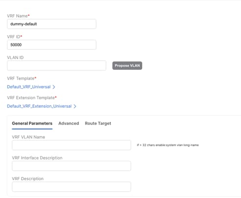
Figure 49 Creating a dummy default VRF in VXLAN EVPN Multi-Site Domain
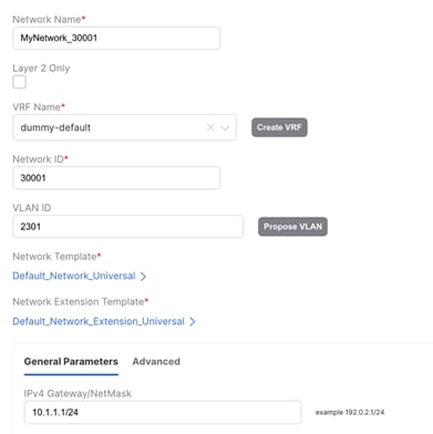
Figure 50 Creating an L3 Network Mapped to Dummy Default with Matching VLAN (as in Enhanced Classic LAN) in VXLAN EVPN Multi-Site Domain. The Gateway is the Distributed Anycast Gateway for VXLAN.
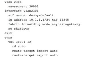
Figure 51 Preview of Distributed Anycast Gateway Configuration
3. L3 network in custom VRF
In this scenario, let’s discuss L3 network in a custom VRF in Enhanced Classic LAN (Figure 52) where Aggregations are the FHRP gateway for these networks. This network is deployed to Access switches with hosts attached.
This scenario is similar to the previous scenario with the exception that instead of creating a dummy default VRF in VXLAN EVPN Multi-Site Domain, you must create a VRF mapping the custom VRF in Enhanced Classic LAN (Figure 53).
Once the migration of gateway is ready to be performed, an L3 Network mapping to this custom VRF, matching VLAN and a new Distributed Anycast Gateway must be created in VXLAN EVPN Multi-Site Domain (Figure 54). This network can be deployed to Border Gateways and Leaf nodes in VXLAN network.

Figure 52 L3 Network in Custom VRF in Enhanced Classic LAN with Aggregation Switches as Gateway
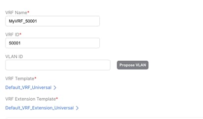
Figure 53 Custom VRF in VXLAN EVPN Multi-Site Domain
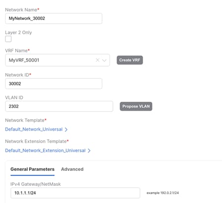
Figure 54 Creating an L3 Network Mapped to Dummy Default with matching VLAN (as in Enhanced Classic LAN) in VXLAN EVPN Multi-Site Domain. The Gateway is the Distributed Anycast Gateway for VXLAN.
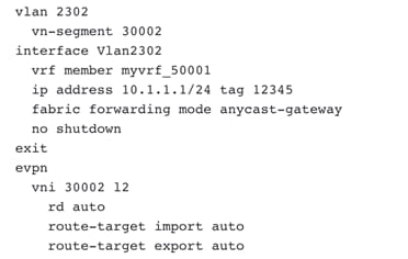
Figure 55 Preview of Distributed Anycast Gateway Configuration
Performing Migration using NDFC (from NX-OS Release 10.2(3) and later)
From NX-OS Release 10.2(3), seamless coexistence of HSRP and Anycast Gateway modes is supported, and this allows keeping the two first-hop gateway modes simultaneously enabled for the same IP subnet.
The Proxy-ARP functionality must be enabled on the VXLAN EVPN Border leaf or Border Gateway nodes or any switches that are providing Layer-2 and Layer-3 Interconnect between VXLAN EVPN fabric and the Classic Ethernet network.
Figure 56 DAG Freeform to push secondary use-bia command on the Border leaf/ Border Gateway nodes show the secondary IP address associated with each DAG SVIs deployed on the VXLAN EVPN Border leaf or Border Gateway nodes.
Note: In NDFC Release 12.1.3b, the configuration for secondary IP use-bia is unavailable. Now, we can leverage network freeform to push the configuration. The UI-based network profile support is planned in the future releases of NDFC.
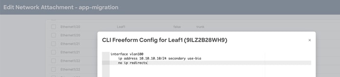
Figure 56 DAG Freeform to push secondary use-bia command on the Border leaf/ Border Gateway nodes
Figure 57 Enable Proxy-ARP Functionality using Port-Type External Command shows the VPC Interface configuration (Layer-2 interconnect) between VXLAN EVPN Border Leaf or Border Gateway nodes and Aggregation switches on Classic Ethernet network. The port-type external command identifies the specific interface on these nodes where Proxy-ARP functionality should be enabled.
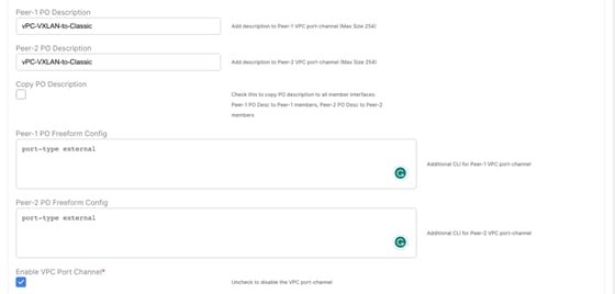
Figure 57 Enable Proxy-ARP Functionality using Port-Type External Command
Reference
For more information, see:
· Configuring VXLAN EVPN Multi-Site
Legal Information
Cisco and the Cisco logo are trademarks or registered trademarks of Cisco and/or its affiliates in the U.S. and other countries. To view a list of Cisco trademarks, go to this URL: https://www.cisco.com/c/en/us/about/legal/trademarks.html. Third-party trademarks mentioned are the property of their respective owners. The use of the word partner does not imply a partnership relationship between Cisco and any other company. (1721R)
Any Internet Protocol (IP) addresses and phone numbers used in this document are not intended to be actual addresses and phone numbers. Any examples, command display output, network topology diagrams, and other figures included in the document are shown for illustrative purposes only. Any use of actual IP addresses or phone numbers in illustrative content is unintentional and coincidental.
© 2020-2023 Cisco Systems, Inc. All rights reserved.