
New and changed information
The following table provides an overview of the significant changes up to this current release. The table does not provide an exhaustive list of all changes or of the new features up to this release.
| Release Version | Feature | Description |
|---|---|---|
|
Nexus Dashboard 4.3.1 |
Secondary-cluster onboarding for ACI fabrics |
Beginning with Nexus Dashboard 4.3.1, you can onboard an ACI fabric from any cluster in a multi-cluster environment that has connectivity to the fabric, including a secondary cluster. For more information about multi-cluster ACI onboarding behavior, see Connecting Clusters. |
|
Nexus Dashboard 4.3.1 |
Support for switches running SONiC images |
Support is now available for certain switches running SONiC (Software for Open Networking in Cloud) images in these Nexus Dashboard fabric types:
For more information, see Understanding switches running SONiC. |
|
Nexus Dashboard 4.3.1 |
Integrated EPG-to-ESG migration for VXLAN-ACI fabric groups |
Beginning with Nexus Dashboard 4.3.1, VXLAN-ACI fabric groups support an integrated workflow for migrating endpoint groups (EPGs) in a Cisco ACI fabric to endpoint security groups (ESGs). This feature guides you through analysis, conversion, and cleanup phases so that you can create migration snapshots, define the migration scope, review EPG-to-ESG mappings and ESG contract relationships, execute the conversion workflow, and remove obsolete legacy policy artifacts. For more information, see Understanding the process for importing tenant policies from ACI fabrics into VXLAN-ACI fabric groups. |
|
Nexus Dashboard 4.3.1 |
Support for non-default-tenant import into VXLAN-ACI fabric groups |
Prior to Nexus Dashboard 4.3.1, support was available only for importing default-tenant into VXLAN-ACI fabric groups. Beginning in Nexus Dashboard 4.3.1, support is now available for importing non-default-tenants into VXLAN-ACI fabric groups. For more information, see Understanding the Nexus One architecture. |
|
Nexus Dashboard 4.3.1 |
Netflow support for Nexus series switches (H1, H2) |
Beginning with Nexus Dashboard 4.3.1, Netflow configuration generated at the fabric level is supported on Nexus series switches (H1, H2) in addition to the previously supported Netflow-capable switch platforms. For more information, see Configuring Netflow support. |
Understanding LAN fabrics, ACI fabrics, and fabric groups

The information in this article applies to LAN fabrics, ACI fabrics, and fabric groups. For information on SAN fabrics, see Creating and Editing SAN Fabrics.
Before you begin creating fabrics or fabric groups, it’s helpful to understand more about each.
Understanding LAN and ACI fabrics
Fabrics are on-premises network regions that include a group of switches and other networking devices that provide connectivity to your applications and endpoints. They may be split in different availability zones (such as pods) that are analyzed and managed by Nexus Dashboard.
There are many types of fabrics:
-
LAN — This type of fabric contains either of these switch types:
-
NX-OS switches — These are a group of Nexus switches running NX-OS software. Nexus Dashboard manages and monitors NX-OS switches using best-practice templates. You can add a fresh set of NX-OS switches for greenfield deployments or onboard existing NX-OS switches to an existing fabric for incremental management and monitoring.
-
Non-Nexus switches and devices — Nexus Dashboard supports onboarding a variety of non-Nexus switches and service appliances such as IOS-XE, IOS-XR, firewalls, and load balancers. These devices support campus VXLAN EVPN fabrics, Layer 4 to Layer 7 (L4–L7) services, and external fabrics that enable east-west or north-south connectivity, such as an IP-based network (IPN), inter-site network (ISN), core, and edge.
-
-
ACI — ACI fabric consists of multiple Cisco N9000 switches running ACI software managed by an Application Policy Infrastructure Controller (APIC) cluster.
-
Monitoring and Analysis: Onboard existing ACI fabrics for continuous telemetry streaming. In environments with restricted connectivity, such as air-gapped networks, you can onboard ACI switches as offline snapshots to perform point-in-time analysis without a direct network connection. You can also use Orchestration to manage and coordinate policies across multiple ACI sites.
-
Nexus Dashboard multi-cluster architecture categorizes fabrics as Local or Remote.
-
Local: A fabric that is present in Nexus Dashboard cluster.
-
Remote: A fabric that is not present in this cluster, but rather is present in another cluster that is part of Nexus Dashboard multi-cluster connectivity.
In addition, local fabrics can be broken down in the following manner:
-
Online fabrics: Fabrics that are connected to Nexus Dashboard over the network.
-
Snapshot fabrics: Fabrics that are referenced by a snapshot for use in one-time analysis or demonstrations. They may or may not be connected to Nexus Dashboard over the network.
And finally, you can either create new fabrics or onboard existing fabrics. Note that before Nexus Dashboard and the individual services were unified into a single product (as described in the Nexus Dashboard Deployment and Upgrade Guide), there were fabric types that were available before unification but might not be available as a new fabric type with the unified product, such as the Legacy Classic LAN fabric type. You can still onboard those existing fabric types but you will not be able to create a new fabric with those pre-unification fabric types. See Mapping fabric types for more information.
Security group selector mapping
Security groups use selectors to classify traffic. The fabric type and network model determine how the system translates these selectors. For more information on security group selector mapping, see Mapping between ND, NX-OS and ACI policies for VXLAN-ACI fabric groups.
Grouping fabrics and clusters
There are several ways to group fabrics and clusters together in Nexus Dashboard:
Grouping Nexus Dashboard clusters
Multi-cluster connectivity: You can establish connectivity between multiple Nexus Dashboard and APIC clusters. For more information, see Connecting Clusters.
Grouping fabrics
The method that you use to group fabrics together differs depending on the type of fabric:
-
NX-OS fabrics: You can group fabrics together using a fabric group, which is a collection of fabrics grouped for visualization or management. The available fabric group types include:
-
VXLAN: A fabric group that is used to interconnect multiple data center VXLAN EVPN fabrics and/or ACI fabrics using border gateways. It can also be used to interconnect Data Center and Campus VXLAN EVPN fabrics. This enables shared overlay deployments for security and segmentation using VXLAN EVPN multisite. The IPN/ISN interconnect network fabric may also be optionally part of this group.
These types of VXLAN fabric groups are available:
-
VXLAN: This subtype of fabric group can contain multiple NX-OS-based Data Center VXLAN EVPN fabrics and/or IOS-XE-based Campus VXLAN EVPN fabrics (which need NX-OS-based border gateways). The DCI network comprising of Multi-Site and External Connectivity or BGP routed fabrics can also be part of this group.
-
VXLAN-ACI: A group that includes a Cisco ACI fabric connected to one or more Cisco NX-OS fabrics using the Nexus One architecture for unified management and policy deployment. For more information, see Understanding the Nexus One architecture.
-
-
Classic: A Classic fabric group can contain Enhanced Classic LAN, Legacy Classic-LAN, Any VXLAN EVPN and External and Inter-fabric connectivity fabrics. This group allows for a combined visualization at a topology level. No group level deployments are available in this fabric group.
-
IP Fabric for Media: A logical group of LAN or IP Fabric for Media (IPFM) fabrics. This type of fabric group can contain individual IPFM/IPFM-Classic/Classic-LAN fabrics. This type of group allows shared host and flow definitions.
-
-
Cisco ACI fabric management models: You can manage ACI fabrics in Nexus Dashboard using one of two methods:
-
Using Cisco ACI in Nexus Dashboard Orchestration
-
Deploys tenants, networks, and policy configurations across multiple ACI sites.
-
Provides a central point for multisite policy consistency and scale.
For more information, see Connecting Multiple ACI Fabrics and Working with Orchestration.
-
-
Using Cisco ACI in a VXLAN-ACI fabric group
-
Enables management and interoperability between Cisco ACI and Cisco NX-OS VXLAN EVPN fabrics.
-
Automates the infrastructure configuration for inter-fabric underlay and overlay connectivity between ACI and NX-OS fabrics.
-
Centralizes the deployment of security and segmentation policies across Cisco ACI and Cisco NX-OS environments.
For more information, see Understanding the Nexus One architecture
-
Constraint: You cannot enable Orchestration on a Cisco ACI fabric that is a member of a VXLAN-ACI fabric group. Similarly, you cannot add a Cisco ACI fabric to a VXLAN-ACI fabric group if Orchestration is enabled. When adding fabrics to a VXLAN-ACI fabric group, any ACI fabrics with Orchestration enabled will not be available to choose.
-
-
Multi-cluster fabric groups: You can create a multi-cluster fabric group that spans multiple Nexus Dashboard clusters to manage VXLAN fabrics across different clusters in a multi-cluster fabric group. For more information, see Create multi-cluster fabric groups.
Mapping fabric types
This table maps fabric types that existed in releases before Nexus Dashboard version 4.1.1 to the new fabric types available in the unified Nexus Dashboard.
-
In some cases, a pre-unification fabric type might not be available as a new deployment type and can only be onboarded into Nexus Dashboard. Those fabric types are marked as "Brownfield onboard only" in this table.
-
Similarly, a new fabric or fabric group type might become available in a unification release that was not available in pre-unification releases. Those fabric or fabric group types are marked as "N/A" in the Pre-unification fabrics fields in this table.
|
Pre-unification fabrics version 3.2.2 and earlier |
Post-unification fabric types version 4.1.1 and later |
|
|
Fabric technologies |
Fabric types |
|
|
LAN |
||
|
N/A |
||
|
VXLAN EVPN |
VXLAN EVPN Multi-Site |
|
|
Multi-Fabric Domain |
Fabric Group |
|
|
VXLAN EVPN |
Data Center VXLAN EVPN |
|
|
eBGP VXLAN EVPN |
BGP fabric |
|
|
VXLAN EVPN |
Campus VXLAN EVPN |
|
|
eBGP Routed |
BGP fabric |
|
|
Classic LAN |
Enhanced Classic LAN |
|
|
Classic LAN |
Classic LAN |
Legacy Classic LAN (Brownfield onboard only) |
|
Custom |
External connectivity network |
|
|
Custom |
Custom network |
|
|
Custom |
Multi-site external network |
|
|
LAN Monitor |
LAN Monitor |
|
|
IPFM |
||
|
IPFM |
IPFM |
|
|
IPFM |
IPFM Classic |
|
|
Generic Multicast |
IPFM Classic |
|
|
Multi-Fabric Domain |
Fabric Group |
|
Guidelines and limitations
-
MTU requirements when onboarding ACI fabrics: Nexus Dashboard, when used with remote leaf switches and Multi-Site architectures in Cisco ACI, requires jumbo MTU (Maximum Transmission Unit) settings on the network switches and on the Nexus Dashboard data interfaces.
Viewing LAN fabric information
These sections describe how to view fabric information.
View information on local online fabrics
Follow these steps to view information on local online fabrics.
-
Navigate to the Fabrics page.
Manage > Fabrics
-
Choose the local scope:
-
For Nexus Dashboard federation: Click the Fabrics tab, then click the Local subtab for the fabrics details page.
-
For standalone cluster: The Local and Remote tabs are not displayed; proceed directly to the next step.
-
-
Choose the fabric type:
-
For snapshot enabled: In the drop-down list underneath the Local tab, choose Online fabrics.
-
For snapshot disabled: The online fabrics and snapshot fabrics options are not displayed. The page displays online fabrics by default.
The table displays this information on already-configured local online fabrics.
Field Description Name
Displays the name of the fabric.
Type
Displays the type of the fabric.
Anomaly level
Displays the highest level of anomalies currently detected in the fabric. Anomalies are classified into these levels.
-
Critical: Shown when the network is down, such as when a fabric is not operational.
-
Major: Shown when connectivity to a given prefix or endpoint could be compromised, such as overlapping IP addresses or subnets.
-
Warning: Shown when the network is impacted, such as when connectivity to a given prefix or endpoint is degraded.
Advisory level
Displays the highest level of advisories currently detected in the fabric. Advisories are classified into these levels.
Advisory levels display only if you have enabled telemetry. Otherwise, Nexus Dashboard displays NA as the advisory level.
-
Critical: Shown when there are unsupported infrastructure and the severity of the bugs associated with notices is Severity1, such as when switches in a fabric are running under End-of-Life conditions or when a critical (Severity1) field notice or security advisory has been issued for a switch or software version currently running in your network.
-
Major: Shown when the severity of the bugs associated with notices is Severity2, such as when a critical (Severity2) field notice or security advisory has been issued for a switch or software version currently running in your network.
-
Warning: Shown when there is support for potentially at-risk infrastructure and the severity of the bugs associated with notices is Severity3, such as when switches in a fabric are approaching end-of-life conditions, or when a Severity3 field notice or security advisory has been issued for a switch or software version currently running in your network.
License tier
Displays the license tier for the software features that is being used in the fabric.
ASN
Displays the ASN for the fabric.
Connectivity status
Shows whether the fabric is reachable from the Nexus Dashboard cluster.
Fabric group
Shows when a fabric is a member of a fabric group.
Features
Shows the features that are enabled on the fabric.
-
-
-
If you want to modify the columns shown in the table, click the gear icon at the top right of the table, then choose the columns that you want to display in the table.
You can also perform these actions on the fabrics list page.
| Action | Description |
|---|---|
|
Actions > Create fabric |
Choose from the category to create a new fabric or onboard and automate configuration of an existing fabric.
|
|
Actions > Edit fabric settings |
Choose a fabric to edit, then click Actions > Edit fabric settings.
|
|
Actions > Delete fabric |
Choose a fabric to delete, then click Actions > Delete Fabric. Click Confirm to delete the fabric. |
|
Actions > Re-register (supports Cisco ACI fabrics only) |
Click Re-register to re-register the connection between Nexus Dashboard and a fabric. |
View information on local snapshot fabrics
Follow these steps to view information on local snapshot fabrics.
-
Navigate to the Fabrics page. Manage > Fabrics
-
Click the Fabrics tab, then click the Local subtab.
-
In the drop-down list underneath the Local tab, choose Snapshot fabrics.
The table displays this information on already-configured local snapshot fabrics.
Field Description Name
Displays the name of the fabric.
Anomaly level
Displays the anomaly level of the fabric. Anomalies are classified into these levels.
-
Critical: Shown when the network is down, such as when a fabric is not operational.
-
Major: Shown when connectivity to a given prefix or endpoint could be compromised, such as overlapping IP addresses or subnets.
-
Warning: Shown when the network is impacted, such as when connectivity to a given prefix or endpoint is degraded.
Advisory level
Displays the advisory level of the fabric. Advisories are classified into these levels.
Advisory levels display only if you have enabled telemetry. Otherwise, Nexus Dashboard displays NA as the advisory level.
-
Critical: Shown when there are unsupported infrastructure and the severity of the bugs associated with notices is Severity1, such as when switches in a fabric are running under End-of-Life conditions or when a critical (Severity1) field notice or security advisory has been issued for a switch or software version currently running in your network.
-
Major: Shown when the severity of the bugs associated with notices is Severity2, such as when a critical (Severity2) field notice or security advisory has been issued for a switch or software version currently running in your network.
-
Warning: Shown when there is support for potentially at-risk infrastructure and the severity of the bugs associated with notices is Severity3, such as when switches in a fabric are approaching end-of-life conditions, or when a Severity3 field notice or security advisory has been issued for a switch or software version currently running in your network.
Type
Displays the type of the fabric.
Connectivity to Nexus Dashboard Insights
Shows the connectivity status for this snapshot fabric.
Features
Shows the features that are enabled on the fabric.
Onboarding Time
Shows the date and time when this snapshot fabric was onboarded.
-
-
If you want to modify the columns shown in the table, click the gear icon at the top right of the table, then select the columns that you want to display in the table.
You can also perform this action on this page.
| Action | Description |
|---|---|
|
Actions > Delete fabric |
Choose a fabric to delete, then click Actions > Delete Fabric. Click Confirm to delete the fabric. |
View information on remote fabrics
Follow these steps to view information on remote fabrics.
-
Navigate to the Fabrics page. Manage > Fabrics
-
Click the Fabrics tab, then click the Remote subtab.
The Remote view on the Fabrics page is visible only when the Nexus Dashboard cluster is part of a multi-cluster federation. In a standalone cluster, the system does not display this Remote view.
The table displays this information on already-configured remote fabrics.
Field Description Name
Displays the name of the fabric.
Type
Displays the type of the fabric.
Owner
Nexus Dashboard cluster where the fabric was created.
License tier
Displays the license tier for the software features enabled on the fabric.
Features
Shows the features that are enabled on the fabric.
-
If you want to modify the columns shown in the table, click the gear icon at the top right of the table, then select the columns that you want to display in the table.
You can also perform this action on this page.
| Action | Description |
|---|---|
|
Actions > Edit fabric settings |
Choose a fabric to edit, then click Actions > Edit fabric settings. |
Creating or onboarding local online LAN fabrics
Guidelines and limitations: Creating or onboarding LAN fabrics
Following are the guidelines and limitations when creating or onboarding local online LAN fabrics:
-
NAT is not supported between the cluster IP addresses and switch management IP addresses.
-
Flow telemetry and in-band management is not supported on Enhanced Classic LAN fabrics.
Create or onboard a local online LAN fabric
Follow these steps to create a local online LAN fabric:
-
Click Manage > Fabrics to navigate to the Fabrics page.
You can view, create, delete, and modify fabrics and fabric groups in this page.
-
Choose Create fabric from Actions drop-down list.
The Create/Onboard Fabric page appears. Navigate through the Create/Onboard Fabric wizard to create a local online fabric.
Select a category
Follow these steps to select a category.
-
Determine what sort of fabric you want to create.
-
Create new LAN fabric: Choose this option to provision a new network comprising of Cisco NX-OS, IOS-XE, or IOS-XR devices through Nexus Dashboard.
-
Onboard existing LAN fabric: Choose this option to preserve an existing Cisco NX-OS, IOS-XE, or IOS-XR devices network’s configuration, and to monitor and automate the deployment of VXLAN, IP media, and Ethernet fabrics through Nexus Dashboard.
-
-
Click Next.
You advance to Select a type.
Select a type
Follow these steps to select a type. See Mapping fabric types for mapping information between pre-4.1.1 fabric types and the fabric types that are available in Nexus Dashboard 4.1.1.
-
Choose the type of fabric that you want to create.
Fabric type Description VXLAN
Used to automate a VXLAN BGP EVPN fabric for Cisco Nexus (NX-OS) or Catalyst (IOS-XE) switches.
Choose which type of VXLAN fabric you want to create:
-
Data Center VXLAN EVPN: Used for a VXLAN EVPN deployment with Nexus 3000 and 9000 switches.
-
Campus VXLAN EVPN: Used for VXLAN EVPN campus deployments with Catalyst 9000 and Cisco N9000 switches as border gateways.
Classic LAN
Used to automate the provisioning of a two- or three-tier traditional classic Ethernet network. This is a fabric for Nexus 3000/7000/9000-based Access-Aggregation-Core Classic LAN architectures. This type is also known as enhanced classic LAN.
AI
Not shown when onboarding an existing LAN fabric. Used to automate the provisioning of a Nexus (NX-OS) fabric for top performance artificial intelligence and machine learning (AI) networks using RoCEv2.
Choose which type of AI fabric that you want to create:
-
AI Routed: Used for eBGP-based CLOS fabrics using Cisco N9000 switches optimized for AI deployments.
-
AI VXLAN EVPN: Used for a VXLAN EVPN deployment with Nexus 3000 and 9000 switches optimized for AI deployments.
The new AI Fabric type deployment options are only available for greenfield deployments.
External and Inter-fabric connectivity
Used to automate provisioning of a network that might include Cisco NX-OS, IOS-XE, IOS-XR, or third-party devices for monitoring or provisioning. This includes use cases for external connectivity and multi-site inter-connectivity (IPNs or ISNs).
Routed
Not shown when onboarding an existing LAN fabric. Used to automate provisioning of BGP-based CLOS fabric on Cisco Nexus (NX-OS) switches.
IP Fabric for Media
Used to automate the creation of IP-based broadcast production networks on Cisco Nexus (NX-OS) switches.
Data Broker
Used to automate the deployment and management of Cisco Nexus Data Broker (NDB) fabrics on Cisco NX-OS switches, enabling efficient TAP and SPAN traffic aggregation. Simplifies the configuration process, streamlines network visibility, and supports scalable monitoring solutions for modern data centers.
-
-
Click Next.
You advance to Settings.
Settings
Follow these steps to configure the settings.
-
Configure the parameters and capabilities of the new fabric.
Field Description Configuration Mode
Determine which type of configuration mode that you want to use to configure this fabric.
-
Default: If you use the Default (basic) mode to create the fabric, you will provide a minimal number of configuration entries during this process so that you are able to create a fabric quickly and easily, and default recommended entries, based on Cisco best practices, are used for the remaining configuration entries that are available for this fabric type. You can then modify those remaining default entries at any point after you’ve created the fabric using the information provided in Editing fabric settings.
-
Advanced: If you use the Advanced mode to create the fabric, you see several more advanced configuration settings in this page. In addition, another step appears in the Create/Onboard Fabric workflow (Advanced settings), where you can create the fabric using more advanced configuration settings.
Nexus Dashboard does not allow you to choose a configuration mode for an NDB fabric. By default, the Default option is chosen. NDB fabric does not support the Advanced mode.
Name
Enter a unique name for the fabric. In Nexus Dashboard 4.3.1, fabric name length is limited to 64 characters.
Location
Choose the location for the fabric.
Overlay routing protocol
Shown in the following situations:
-
You chose one of the Data Center VXLAN EVPN fabric types in 2. Select a type (either Data Center VXLAN EVPN or AI Data Center VXLAN EVPN).
-
You clicked Advanced in the Configuration Mode field above.
Choose the type of overlay routing protocol:
-
iBGP: Interior Border Gateway Protocol. Used to set up a link between the same Autonomous Systems (AS).
-
eBGP: Exterior Border Gateway Protocol. Used to establish a connection between two distinct Autonomous Systems.
VRF-Lite protocol
Shown in the following situations:
-
You chose Classic as the fabric type in 2. Select a type.
-
You clicked Advanced in the Configuration Mode field above.
Choose the VRF-Lite Agg-Core/Edge or Collapsed Core-WAN peering protocol:
-
EBGP
-
OSPF
-
None: Nexus Dashboard does not configure the peering protocol if the None option is selected. You must manually configure the peering protocol with this option, if necessary.
BGP ASN/BGP ASN for spines
Available for these fabric types.
-
VXLAN (BGP ASN for spines)
-
Classic (BGP ASN)
-
AI (BGP ASN for spines)
-
External and inter-fabric connectivity (BGP ASN)
-
Routed (BGP ASN for spines)
Enter the BGP autonomous system number (ASN) for the fabric’s spine switches. Valid entries are:
1-4294967295 | 1-65535[.0-65535]where:
-
1-4294967295denotes an integer (whole) value from 1 to 4294967295 (inclusive), or -
1-65535[.0-65535]denotes a decimal value, where the left side of the decimal is a number from 1 to 65535 (inclusive) and the right side of the decimal is a value from 0 to 65535 (inclusive).
Following are examples of valid entries that would fall into either category above:
-
1 -
31 -
7654321 -
1.1 -
1.65535 -
2.999 -
65535.1
Following are examples of invalid entries that would violate the guidelines shown above:
-
-5 -
1.300000 -
65536.1
The BGP ASN field is not supported for NDB fabrics.
Network operating system
This field appears if you clicked Advanced in the Configuration mode.
Choose the version of network operating system that you want to use for this fabric.
-
NX-OS
-
SONiC
For more information on the SONiC network operating system, see Understanding switches running SONiC.
-
The SONiC network operating system is available only for certain switches, as described in Understanding switches running SONiC.
-
A fabric that contains switches running SONiC images can only contain those switch types. You cannot have a mix of switches running SONiC images and other switch types in the same fabric.
-
Choosing the SONiC option also automatically enables these options in this page:
-
Telemetry
-
Telemetry collection: Out-of-band
-
Telemetry streaming via: IPv4
These are the only valid supported options in these areas when using SONiC as the network operating system and cannot be changed.
-
-
In addition, certain configuration options might not be applicable and therefore are not shown if you choose the SONiC option.
-
SONiC does not support decimal values for the BGP ASN for the fabric’s spine switches, so Nexus Dashboard automatically converts decimal values entered in the BGP ASN for spines field into integer (whole) values.
-
License tier for fabric
Choose the licensing tier for the fabric:
-
Essentials
-
Advantage
-
Premier
Click on the information icon (i) next to License tier to see what functionality is enabled for each license tier.
NDB fabric currently supports only the Essentials license tier.
Fabric designer
This option allows you to design and build your fabric before purchasing the equipment. To enable Fabric Designer option, check the Quickly build a cable prior to equipment purchase check box.
Once you check the Quickly build and cable prior to equipment purchase check box, the Fabric designer settings option appears in the left navigation pane. Note that the Fabric designer option is applicable only for data center VXLAN EVPN fabrics. For more information, see Working with Fabric Designer in Nexus Dashboard.
The Fabric designer settings option appears after the Settings step in the left navigation pane, when you choose the Default configuration mode. If you choose Advanced configuration mode, this option appears after Advanced settings step.
Enabled features
Check the Telemetry check box to enable telemetry for the fabric. This is the equivalent of enabling the Nexus Dashboard Insights service in previous releases. The Telemetry option is only visible if you have checked the Telemetry check box in the Settings page while configuring parameters during fabric creation.
Enabling telemetry in Default configuration mode supports only in-band mode. To enable out-of-band (OOB) telemetry collection, you must select Advanced configuration mode.
For NDB fabrics, Auto network adaptation - Dynamically adapts to changes in the network layout without manual intervention option is available. If the inter-switch links between devices change, Nexus Dashboard updates the involved interfaces to deny traffic and redeploys user connections using the new route. You can edit this option as needed. NDB fabrics does not support telemetry. For more information, see Understanding NDB Fabrics and Switches.
Telemetry collection
This option becomes available if:
-
You enabled Telemetry in the Enabled features field, and
-
You clicked Advanced in the Configuration Mode field.
Choose either Out-of-band or In-band for telemetry collection.
Telemetry streaming via
This option becomes available if:
-
You enabled Telemetry in the Enabled features field, and
-
You clicked Advanced in the Configuration Mode field.
Choose either IPv4 or IPv6 for telemetry streaming.
Telemetry VRF
This option becomes available if:
-
You enabled Telemetry in the Enabled features field, and
-
You clicked Advanced in the Configuration Mode field.
Enter the appropriate VRF instance in this field.
Telemetry source interface
This option becomes available if:
-
You enabled Telemetry in the Enabled features field, and
-
You clicked Advanced in the Configuration Mode field.
Enter the source interface for telemetry streaming.
Security domain
This field appears if you clicked Advanced in the Configuration mode.
Choose the security domain for the fabric.
-
-
Click Next to advance to the next step in the fabric creation process.
-
If you chose Default in the Configuration Mode field above, the next step in the Create/Onboard Fabric workflow is Fabric summary.
-
If you chose Advanced in the Configuration Mode field above, the next step in the Create/Onboard Fabric workflow depends on the type of fabric that you are creating.
-
If you are creating an AI fabric, you advance to AI Settings.
-
If you are creating any other type of fabric (a non-AI fabric), you advance to Advanced settings.
-
-
AI Settings
For AI fabrics, follow these steps to configure the AI settings.
-
Configure the parameters and capabilities of the new fabric.
Field Description Policy selection mode
Not displayed if you chose SONiC as your network operating system.
Choose the QoS policy based on your fabric link speed:
-
User-defined (custom configuration)
-
800G
-
400G
-
100G
-
25G
See AI QoS classification and queuing policies for more information.
Dynamic load balancing
Click to Enable the options. Choose the Mode selection from the drop-down list and enter the aging period in the Flowlet aging time field. For more information, see Add a Dynamic Load Balancing (DLB) policy template.
-
Flowlet aging is applicable when you choose the flowlet, policy driven flowlet, or policy driven mixed mode mode option from the Dynamic_Load_Balancing_mode drop-down list when you add a Dynamic Load Balancing (DLB) policy template. It is not effective when you choose the per packet or policy driven per packet mode option from the Dynamic_Load_Balancing_mode drop-down list.
-
The NX-OS CLI does accept a flowlet aging value, regardless of the mode; however, it may have a
no operationresult based on the mode choice.
-
-
Click Next.
You advance to Advanced settings.
Advanced settings
When you create a fabric using these procedures, the standard workflow allows you to create a fabric using the bare minimum settings so that you are able to create a fabric quickly and easily. However, you can make more advanced configurations on this fabric, either by clicking Advanced in the Configuration Mode field as part of this fabric creation workflow or after you have completed this fabric configuration workflow.
Follow these steps to configure the advanced settings.
-
Locate the article that provides information on each of the available fields for the configuration settings for your fabric type.
See Editing fabric settings for more information on these advanced configuration settings for different types of fabrics.
-
Make the necessary advanced configuration changes for your fabric using the Editing Fabric Settings article for your fabric type.
-
Return to these procedures after you have completed the advanced configurations for your fabric type, then click Next.
You advance to Fabric summary.
Fabric summary
Follow these steps to view the fabric summary.
-
Verify all of the information that is shown in the Fabric summary page is correct.
-
If all of the information shown in the page looks correct, click Submit.
You advance to Fabric creation.
Fabric creation
Follow these steps to monitor the fabric creation.
-
Monitor the creation of the fabric.
You can see the fabric creation progress in this page. If you close the session, your fabric will still be created.
-
When the fabric creation is completed, determine your next step.
-
To bring up the Overview page for the fabric that you just created, click View fabric details.
-
To go back to the main Fabrics page with all of the configured fabrics in your cluster listed, click View all fabrics.
-
If you want to create another fabric at this time, click Create another fabric, then repeat these procedures.
-
Add switches to the fabric
Follow these procedures to add switches to the fabric:
-
Navigate to the Overview page for the fabric.
-
Click Manage > Fabrics > Fabrics.
-
Click on the fabric where you want to add a switch.
-
-
Click the Inventory tab.
-
Click the Switches subtab.
-
Click Actions > Add Switches, then enter the necessary information to add the switch to the fabric. Refer to the "Adding Switches to Your Fabric" article for more information.
Editing fabric settings
The following table provides pointers to articles that describe how to edit fabric settings for each type of fabric.
|
Type of Fabric |
Detailed Procedures |
|
ACI fabric |
|
|
AI Routed fabric |
|
|
AI Data Center VXLAN fabric |
|
|
Campus VXLAN fabric |
|
|
Classic fabric |
|
|
Data Center VXLAN fabric |
|
|
External fabric |
|
|
IPFM fabric |
|
|
Routed fabric |
|
|
Data Broker fabric |
Onboard ACI fabrics
Follow these steps to onboard ACI fabrics.
-
Navigate to the Fabrics page.
Manage > Fabrics
-
Choose Fabrics > Local.
-
In the drop-down underneath the Local tab, choose Online fabrics.
See Understanding LAN fabrics, ACI fabrics, and fabric groups for more information on the different types of local fabrics.
-
Click Create Fabric.
The Select a category step in the fabric creation process appears.
-
In the Onboard ACI fabric area, click Connect APIC cluster to start the onboarding workflow.
In a multi-cluster environment, you can onboard the ACI fabric from any cluster that has connectivity to the fabric, including a secondary cluster. After onboarding is complete, the fabric becomes available in the multi-cluster environment. For complete information about multi-cluster ACI onboarding behavior, fabric visibility, and deregistration, see Connecting Clusters.
+ The Connect Cluster page appears. Refer to the Connecting Clusters article for the procedures on connecting the APIC cluster.
You can also navigate to the Connect Cluster page by navigating to:
Admin > System Settings > Multi-cluster connectivity
and clicking on Connect Cluster.
Onboard ACI fabrics for VXLAN-ACI
Follow these steps to onboard ACI fabrics for VXLAN-ACI.
If you are onboarding the ACI fabric in a multi-cluster environment, see Connecting Clusters for information about onboarding from a secondary cluster and deregistration behavior.
-
Navigate to Manage > Fabrics
-
From the Actions drop-down list, choose Create fabric.
-
On the Create/Onboard Fabric page, choose Onboard ACI fabric.
-
On the Select type section, choose ACI, and then click Next.
-
On the Settings section, perform these actions:
-
Enter the Hostname/IP address.
-
Enter the Username and Password.
-
(Optional) Enter the Login domain — if you leave this field empty, the site’s local login is used.
-
(Optional) Check the Validate peer certificate — allows Nexus Dashboard to verify that the certificates of hosts to which it connects (such as site controllers) are valid and are signed by a trusted Certificate Authority (CA)checkbox.
-
-
Click Next.
-
On the Onboard fabric section, perform these actions:
-
Enter the Fabric name and Location details.
-
(Optional) Choose Essentials from the License tier option.
-
(Optional) In Enable Telemetry, check the Telemetry check box.
Telemetry must be enabled for Nexus One implementation.
-
(Optional) Choose the Telemetry collection option.
-
(Optional) Choose the Telemetry streaming option.
-
(Optional) In the Advance options section, choose from the Security domain drop-down list.
-
-
Click Next.
-
Review the details on Summary page and click Connect. After successful creation, the Create/Onboard Fabric page appears.
Onboard snapshot LAN fabrics
To onboard a local snapshot LAN fabric:
-
Enable the snapshot feature at the system level, if necessary.
-
Navigate to Admin > System Settings.
-
With the General tab selected, locate the Advanced Settings area.
-
Determine if the Fabric snapshot creation feature is enabled or not.
-
If you see Enabled under the Fabric snapshot creation field, this feature has already been enabled. Go to Step 2.
-
If you see Disabled under the Fabric snapshot creation field, continue with these procedures.
-
-
Click Edit in the Advanced Settings area.
The Advanced settings slide-in pane appears.
-
Click the checkbox next to Enable fabric snapshot creation to enable this feature, then click Save.
You will now see Enabled under the Fabric snapshot creation field.
-
-
Navigate to the Fabrics page.
Click Manage > Fabrics to navigate to the Fabrics page. You can view, create, delete, and modify fabrics and fabric groups in this page.
-
Click the Fabrics tab, then click the Local subtab.
-
In the dropdown underneath the Local tab, choose Snapshot fabrics.
See Understanding LAN fabrics, ACI fabrics, and fabric groups for more information on the different types of local fabrics.
-
Click Create fabric.
The Create Fabric page appears. Navigate through the Create Fabric wizard to create a local snapshot fabric.
Select a category
-
Click Onboard Snapshot fabric.
This allows you to onboard a snapshot fabric, which will have no Internet connectivity on the controllers or switches.
-
Click Next.
You advance to Basic settings.
Basic settings
-
Determine if you have a fabric snapshot file.
-
If you have a fabric snapshot file, choose that file or drag and drop to upload the file into the Upload file area.
-
If you don’t have a fabric snapshot file yet:
-
Click Download Script to download the
data-collectors.tar.gzto your machine. -
Extract the file you downloaded and run the data collection script. Follow the instructions provided in the readme.md file. After the script is completed successfully, the data is collected in a
<filename>.tar.gzfile.
The collection script requires that you have Python3 installed on your system.
-
Choose the file or drag and drop to upload the file into the Upload file area.
-
-
-
Click Next
-
Enter the fabric name to identify the fabric on Nexus Dashboard.
-
Choose the fabric location from the map to identify the fabric on Nexus Dashboard.
-
Click Next.
-
Verify the configuration.
-
Click Submit.
After your fabric is onboarded and fully prepared, Nexus Dashboard will start the analysis to collect data from your fabric and display the fabric information in the Fabrics page. For more information, see Fabric summary. The Fabric Analysis banner displays the progress of the analysis. The time to run the analysis depends on the size of the fabric.
-
Click Next.
You advance to Fabric summary.
Fabric summary
-
Verify all of the information that is shown in the Fabric summary page is correct.
-
If all of the information shown in the page looks correct, click Submit.
Create fabric groups
You can create groups of VXLAN fabrics to form a VXLAN fabric group or to support logical groups of LAN or IPFM fabrics for simplified management.
-
Click Manage > Fabrics, then choose Fabric groups to navigate to the Fabric groups page.
You can view, create, delete, and modify fabric groups on this page.

If you are creating a VXLAN-ACI fabric group, click the learn more link in VXLAN-ACI fabric groups description in the Fabric groups page to bring up a detailed walkthrough of the stages that you must go through to successfully create a VXLAN-ACI fabric group.
-
Click Actions > Create fabric group.
The Create fabric group page appears. Navigate through the Create fabric group wizard to create a fabric group.
Settings
-
Enter a name for the fabric group in the Name field.
-
Choose the type of fabric group that you want to create.
If you choose VXLAN as the fabric group type, an additional step in the Create fabric group workflow appears (Advanced settings). Advanced settings are available only for VXLAN fabric group types and not for any other fabric group types.
Type Description VXLAN
Choose from these VXLAN fabric group subtypes:
-
VXLAN: A VXLAN fabric group can contain individual VXLAN, external, or enhanced classic LAN fabrics. This type of fabric group allows for shared deployments for VXLAN overlays (networks and VRFs) and fabric interconnectivity.
-
VXLAN-ACI: A VXLAN-ACI fabric group, part of the Nexus One, integrates VXLAN, external, enhanced classic LAN, and ACI fabrics. The fabric manager manages this specialized VXLAN fabric group across heterogeneous ACI and NX-OS fabrics, and supports shared deployments for VXLAN overlays (networks and VRFs) and inter-fabric connectivity.
Classic
A classic fabric group can contain enhanced classic LAN, classic LAN, or external fabrics. This fabric group allows for a combined visualization at a topology level. No group level deployments are available in this fabric group.
IP Fabric for Media
An IP Fabric for Media (IPFM) fabric group can contain individual IPFM, IPFM classic, or classic LAN fabrics. This type of fabric group allows for shared host and flow definitions.
-
-
Click Next to advance to the next step in the fabric group creation process.
-
If you chose VXLAN or VXLAN-ACI in the Type field above, the next step in the Create fabric group workflow is Advanced settings.
-
If you chose Classic or IPFM in the Type field above, the next step in the Create fabric group workflow is Fabric group summary.
-
Advanced settings
-
Locate the Editing Fabric Settings for Fabric Groups article, which provides information on each of the available fields for the configuration settings for the VXLAN fabric group.
-
Make the necessary advanced configuration changes for your fabric group using the information provided in "Editing Fabric Settings for Fabric Groups" article.
-
Return to these procedures after you have completed the advanced configurations for your fabric group, then click Next.
You advance to Fabric group summary.
Fabric group summary
-
Verify all of the information that is shown on the Fabric group summary page is correct.
-
If all of the information shown in the page looks correct, click Submit.
You advance to Fabric group creation.
Fabric group creation
-
Monitor the creation of the fabric group.
You can see the fabric group creation progress on this page. If you close the session, your fabric group will still be created.
-
When the fabric group creation is completed, determine your next step.
-
To bring up the Overview page for the fabric group that you just created, click View fabric group details.
-
To go back to the main Fabric groups page with all of the configured fabric groups in your cluster listed, click View all fabric groups.
-
If you want to create another fabric group at this time, click Create another fabric group, then repeat these steps.
-
Add member fabrics to the fabric group
-
If the member fabric is a VXLAN EVPN fabric, make sure that the Underlay Routing Loopback IP Range and the Underlay VTEP Loopback IP Range pool values do not overlap with any existing member fabric within the fabric group, so there is no IP address conflict on the routing loopback interface or the VTEP loopback interface.
-
Before you add a Cisco NX-OS fabric to a VXLAN-ACI fabric group, enable Security Groups Pre-provisioning in the Cisco NX-OS fabric settings. If you do not enable this setting, an error occurs when you add the fabric to the group.
-
Ensure that these parameters are the same across Cisco NX-OS fabrics and in each VXLAN-ACI fabric group:
-
anycast gateway MAC address - This address must match the APIC default bridge domain (BD) MAC address (0022.bdf8.19ff).
-
security group name prefix, and
-
security group tag (SGT) ID range.
-
Follow these steps to add member fabrics to a fabric group.
-
Navigate to the Overview page for the fabric group.
-
Click Manage > Fabrics > Fabric Groups.
-
Click on the fabric group where you want to add member fabrics.
-
-
Click the Inventory tab.
-
Click the Member fabrics subtab.
-
Click Actions > Add member fabric.
A list of available member fabrics appears.
-
On the Add member fabric page, click a member fabric that you want to add to the fabric group.
You can add only one member fabric at a time on this page.
When adding member fabrics to a VXLAN-ACI fabric group, you must add the ACI fabric first. ACI fabrics require border gateways, must not have Orchestration enabled, and can belong to only one VXLAN-ACI fabric group. In addition, telemetry should have been enabled for all Cisco ACI fabrics during onboarding. This is required for Nexus Dashboard to manage Cisco ACI as part of a Nexus One architecture.
-
Click Select.
The member fabric now appears under the Member fabrics tab for this fabric group.
-
From the Actions drop-down list, click Recalculate and deploy.
-
Repeat steps 4 - 7 to add additional member fabrics to this fabric group.
Delete fabric groups
Follow these steps to delete fabric groups.
-
Navigate to the Fabric groups page.
-
Click Manage > Fabric to navigate to the Fabric page.
-
Click Fabric groups.
-
-
Choose the fabric group that you want to delete.
The Overview page for that fabric group appears.
-
Remove member fabrics from the fabric group that you want to delete.
You must remove member fabrics from the fabric group before you can delete the fabric group, with the ACI fabric being the last one.
-
Click Inventory > Member fabrics.
-
Choose the first member fabric to delete from the fabric group.
If you have a VXLAN-ACI fabric group, do not remove the ACI fabric first.
-
Click Actions > Remove fabric from fabric group.
-
Repeat these steps to remove all fabrics from the fabric group, with an ACI fabric being the last fabric to remove from the fabric group.
-
Click ← Back to return to the Fabric groups page.
-
-
In the Fabric groups page, choose the fabric group that you want to delete and click Actions > Delete Fabric Group.
Connect ACI and NX-OS fabrics
-
Choose Connectivity > Links verify that the link between your external fabric and the ACI fabric name is listed. For more information, see Grouping fabrics and clusters.
Follow these steps to configure inter-fabric underlay and overlay connectivity.
-
Navigate to Manage > Fabrics > Fabric groups
-
From the Name column, click the fabric.
-
Choose Recalculate and deploy from the Actions drop-down list.
The system displays the progress percentage as the recalculation moves through several stages. When the process completes, the Deploy Configuration page displays the fabric names and their statuses.
-
Choose Connectivity > Links for the fabric group. Verify that the following logical and physical links are displayed:
-
Underlay links: Locate the
vxlanAciMultisiteUnderlaypolicy name, which represents the border gateway (BGW) to inter-fabric network (IFN) connectivity. -
Overlay links: Locate the
vxlanAciOverlaypolicy name, which represents the full-mesh Ethernet VPN (EVPN) adjacencies between the ACI and Cisco NX-OS border gateways.
-
-
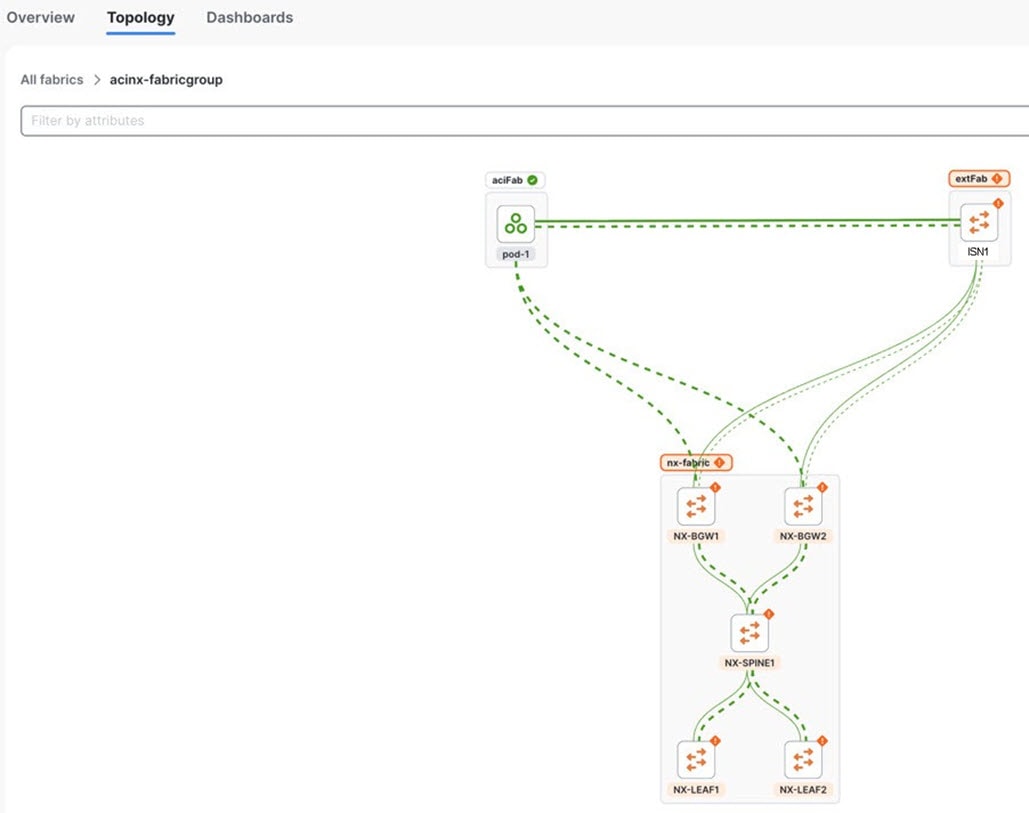
Choose Home > Topology to verify the links.
Create multi-cluster fabric groups
A multi-cluster fabric group is a logical container for VXLAN fabrics that are managed across multiple Nexus Dashboard clusters. To create a multi-cluster fabric group, you must integrate the participating Nexus Dashboard clusters into a federation (also known as one-manage).
-
Multi-cluster fabric group requirement: You must establish multi-cluster connectivity and federate the clusters before you can create a multi-cluster fabric group.
-
Primary cluster dependency: Create and manage multi-cluster fabric groups from the federation primary cluster. The primary cluster automatically synchronizes settings to all secondary clusters in the federation.
-
Fabric type limitation: Multi-cluster fabric groups support standard VXLAN fabrics only. VXLAN-ACI fabric group type is restricted to a single Nexus Dashboard cluster and does not support federation or multi-cluster management.
Guidelines and limitations for creating a multi-cluster fabric group
-
If you are viewing a single cluster, you can create fabrics and fabric group within a single cluster.
-
On the All Clusters > Fabrics page, you can view all the fabrics from all the member clusters. On the Fabric groups tab, you can view all the fabric groups from all the member clusters.
-
Even though the button displays as Create fabric group on the All Clusters > Multi-cluster fabric groups page, Nexus Dashboard creates a multi-cluster fabric group rather than a fabric group.
-
On the All Clusters page, if you click on Primary, you see the member fabrics for the primary cluster.
-
The health status for an NX-OS fabric will be shown if that fabric is owned by the cluster that you are viewing, but the health status will not be shown for an NX-OS fabric that is owned by another cluster in a multi-cluster fabric group.
-
Multi-cluster fabric groups support only standard Data Center VXLAN EVPN, including iBGP and External and Inter-Fabric Connectivity member fabric types.
-
Data Center VXLAN EVPN - external Border Gateway Protocol (eBGP) fabrics are not supported as multi-cluster fabric group members. You cannot add a standalone Data Center VXLAN EVPN - eBGP fabric directly to a multi-cluster fabric group, nor can you add a Multi-Site Domain (MSD) or fabric group that contains a Data Center VXLAN EVPN - eBGP member fabric.
-
-
Managing the same physical switch from more than one cluster is not supported in multi-cluster fabric group configurations. This unsupported configuration can affect topology views and deployment of inter-fabric connections in multi-cluster fabric groups.
Configure a multi-cluster fabric group
Follow these steps to configure a multi-cluster fabric group.
-
Ensure that you have configured multiple clusters for multi-cluster connectivity. For more information on multi-cluster connectivity in Nexus Dashboard, see the section "Connecting Nexus Dashboard clusters" in Connecting Clusters.
-
Navigate to All Clusters > Clusters and click on All Clusters.
-
Click Manage > Fabrics to navigate to the Fabrics page. You can view, create, delete, and modify fabrics and fabric groups on this page.
-
Click the Multi-cluster fabric groups tab.
You can see the multi-cluster fabric groups that have already been created on the Multi-cluster fabric groups page.
-
Click Create Fabric Group.
The Create multi-cluster fabric group page appears.
-
Navigate through the Create multi-cluster fabric group wizard to create a multi-cluster fabric group.
VXLAN is the default domain for creating multiple VXLAN and External fabrics.
-
Click Next.
-
Follow the steps for creating a fabric group. For more information, see Create fabric groups.
Add member fabrics to a multi-cluster fabric group
Follow these steps to add member fabrics to a multi-cluster fabric group.
-
Navigate to the All Clusters page for a multi-cluster fabric group.
-
Click Manage > Fabrics > Multi-Cluster fabric groups.
-
Click on the multi-cluster fabric group where you want to add a member fabric.
-
Click the Inventory tab.
-
Click the Member Fabrics subtab.
-
Click on the member fabric that you want to add to the multi-cluster fabric group.
-
Click Actions > Add member fabric.
A list of supported member fabrics appears on the Add member fabric page. Only Data Center VXLAN EVPN - iBGP fabrics and External and Inter-Fabric Connectivity fabrics are eligible member fabrics.
-
On the Add member fabric page, click a member fabric that you want to add to a multi-cluster fabric group.
You can add only one member fabric at a time on this page.
-
Click Select.
The member fabric now appears under the Member Fabrics tab for this multi-cluster fabric group.
-
From the Actions drop-down list, click Recalculate and deploy.
-
Repeat steps 6 - 10 to add additional member fabrics to this multi-cluster fabric group.
Remove member fabrics from a multi-cluster fabric group
Follow these steps to remove member fabrics from a multi-cluster fabric group.
-
Navigate to the All Clusters page for a multi-cluster fabric group.
-
Click Manage > Fabrics > Multi-Cluster fabric groups.
-
Click on the multi-cluster fabric group where you want to remove a member fabric.
-
Click the Inventory tab.
-
Click the Member Fabrics subtab.
-
Click on the member fabric that you want to remove from the multi-cluster fabric group.
-
From the Actions drop-down list, click Actions > Remove member fabric.
-
Click Ok.
The member fabric no longer displays under the Member Fabrics tab for this multi-cluster fabric group.
-
From the Actions drop-down list, click Recalculate and deploy.
-
Repeat steps 5 - 9 to remove additional member fabrics from this multi-cluster fabric group.
Back up and restore multi-cluster fabric group configurations
Back up multi-cluster fabric group configurations
Follow these steps to back up a multi-cluster fabric group configuration.
-
Navigate to the All Clusters page for a multi-cluster fabric group.
-
Click Manage > Fabrics > Multi-Cluster fabric groups.
-
Click on the appropriate multi-cluster fabric group to display the overview information for that fabric group.
-
Click Actions > Maintenance > Backup Fabric Group.
The Create Fabric Backup page appears.
-
In the Backup Tag area, enter a name for the backup, then click Create Backup.
Restore multi-cluster fabric group configurations
Follow these steps to restore a multi-cluster fabric group configuration.
-
Navigate to the All Clusters page for a multi-cluster fabric group.
-
Click Manage > Fabrics > Multi-Cluster fabric groups.
-
Click on the appropriate multi-cluster fabric group to display the overview information for that fabric group.
-
Click Actions > Maintenance > Restore Fabric Group.
The Restore Fabric Group page appears.
-
Review the backups shown on this page.
This table describes the columns that appear on the Select Backup tab.
Fields Descriptions Backup Date
Specifies the backup date.
Backup Version
Specifies the version of backup.
Backup Tag
Specifies the backup name.
Backup Type
Specifies the backup type (for example, a golden backup).
This table describes the fields that appear on the Action tab.
Actions Descriptions Mark as golden
To mark an existing backup as a golden backup, choose Mark as golden. Click Confirm in the confirmation dialog-box.
Remove as golden
To remove an existing backup from a golden backup, choose Remove as golden. Click Confirm in the confirmation dialog-box.
-
In the Select Backup step, click the radio button for the fabric backup that you want to restore, then click Next.
-
In the Restore Preview step, verify that the information is correct for the backup that you want to restore.
You can preview the details about the configuration in the backup file. You can also view the name and serial numbers for the switches in the Fabric backup. Click on Delta Config to view the configuration difference on the switches in the fabric.
-
Click Restore Intent.
-
In the Restore Status step, you can view the status of restoring the intent.
-
Click Next to view the preview configuration.
-
In the Configuration Preview step, you can resync the configurations on specific switches.
For the desired switch, check the Switch Name check box, and click ReSync.
-
Click Deploy to complete the Restore Fabric Group operation.
Migrate a Nexus Dashboard 3.2.x Orchestration-managed fabric to a multi-cluster fabric group
You can migrate a Nexus Dashboard 3.2.x Orchestration-managed fabric to a Nexus Dashboard 4.3.1 multi-cluster fabric group. For more information on a Nexus Dashboard 3.2.x multi-cluster fabric, see Managing and Monitoring Multi-Cluster Fabrics Using One Manage, Release 12.2.2/12.2.3.
Prerequisites for migrating a Nexus Dashboard 3.2.x Orchestration-managed fabric to a multi-cluster fabric group
-
Upgrade from Nexus Dashboard 3.2.x to Nexus Dashboard 4.3.1. For more information, see Upgrade from Nexus Dashboard 3.2.x to Nexus Dashboard 4.3.1.
-
Configure at least two clusters for multi-cluster connectivity. For more information, see the section "Create or onboard a local online LAN Fabric" in Creating Fabrics and Fabric Groups.
-
Onboard all the clusters that were managed by Nexus Dashboard Orchestrator. For more information, see Connecting Clusters, Release 4.1.1
-
You can add either a remote user or a local user accessing from primary cluster using the multi-cluster login domain. For more information, see the section "Add primary cluster as remote authentication domain" in Configuring Users, Roles, and Security.
You need to add a local user for the VXLAN multi-cluster fabric group domain.
Guidelines and limitations for migrating a Nexus Dashboard 3.2.x Orchestration-managed fabric to a multi-cluster fabric group
-
You can migrate any Nexus Dashboard 3.2.x Orchestration-managed fabric to a Nexus Dashboard 4.3.1 multi-cluster fabric group.
-
After upgrading to Nexus Dashboard 4.3.1, we do not recommend adding VRFs or networks before migrating to a multi-cluster fabric group.
Upgrade from Nexus Dashboard 3.2.x to Nexus Dashboard 4.3.1
Refer to the "Upgrading an Existing Nexus Dashboard Cluster to This Release" section in the Cisco Nexus Dashboard Deployment and Upgrade Guide, Release 4.1.x for upgrade procedures.
How to migrate a Nexus Dashboard 3.2.x Orchestration-managed fabric to a multi-cluster fabric group
Follow these steps to migrate a Nexus Dashboard 3.2.x Orchestration-managed fabric to a Nexus Dashboard 4.3.1 multi-cluster fabric group.
-
Connect your Nexus Dashboard clusters. For more information, see the section "Connecting multiple ACI fabrics through the Orchestration page" in Connecting Multiple ACI Fabrics and Working with Orchestration.
After migration, Nexus Dashboard converts the Multi-Site Orchestration (MSO) fabric type to a VXLAN fabric type.
You now have two connected clusters using the VXLAN fabric type.
-
Log in as a super-admin, admin, or fabric-admin.
Nexus Dashboard requires a fabric admin in a multi-cluster fabric group.
-
Configure a multi-cluster fabric group as a regular user from the primary cluster. For more information, see Create multi-cluster fabric groups.
-
Ensure that all the Orchestration-managed fabrics are in-sync before adding the Orchestration-managed fabrics to a multi-cluster fabric group.
-
Add the fabric groups managed by Nexus Dashboard Orchestration as a member to a multi-cluster fabric group. You should migrate Orchestration-managed fabrics from all the clusters managed by Nexus Dashboard Orchestration. For more information, see Add member fabrics to a multi-cluster fabric group.
-
Perform a Recalculate and deploy operation.
This will migrate the multisite overlay links to the multi-cluster fabric group. You can manage the multisite underlay port configuration pushed by NDO in the future by editing the policies with the template name
multisite_dci_underlay_sitelocal_jythonfrom the individual fabrics. For more information, see Working with Configuration Policies for Your Nexus Dashboard LAN or IPFM Fabrics.
+ After migrating an Orchestration-managed fabric from Nexus Dashboard 3.2.x, we do not expect there to be a difference in the configurations.
-
Ensure that there are no pending configurations after performing a Recalculate and deploy operation.
-
Create a network or add a VRF. For more information, see the sections "Working with VRFs" and "Working with networks" in Working with Segmentation and Security for Your Nexus Dashboard VXLAN Fabric.
View the migrated multi-cluster fabric group on the Topology page
You can view the migrated multi-cluster fabric group on the Topology page after migrating your Nexus Dashboard 3.2.x Orchestration-managed fabric to a Nexus Dashboard 4.3.1 multi-cluster fabric group.
Follow these steps to view the migrated multi-cluster fabric group details on the Topology page.
-
Navigate to All Clusters > Clusters and click on All Clusters.
-
Navigate to Home > Topology.
Nexus Dashboard displays the network topology from the connected clusters.
Additional settings
The following sections provide information for additional settings that might be necessary when creating LAN fabrics or fabric groups.
Understanding the Fabric Summary page
Click on a fabric to open the side kick panel. The following sections display the summary of the fabric:
-
Health - Shows the health of the Fabric.
-
Alarms - Displays the alarms based on the categories.
-
Fabric Info - Provides basic about the Fabric.
-
Inventory - Provides information about Switch Configuration and Switch Health.
Click the Launch icon to the right top corner to view the Fabric Overview.
Advanced settings
Follow these steps to enable the advanced settings option.
-
Navigate to Admin > System Settings.
-
With General selected, locate the Advanced settings area.
-
Determine if the Display advanced settings and options for TAC support feature is enabled or not.
-
If you see Enabled under the Display advanced settings and options for TAC support field, this feature has already been enabled.
-
If you see Disabled under the Display advanced settings and options for TAC support field:
-
Click Edit in the Advanced settings area.
The Advanced settings page appears.
-
Check the Display advanced settings and options for TAC support check box to enable, then click Save.
You will now see Enabled under the Display advanced settings and options for TAC support field.
-
-
-
In the Routes area, click Edit.
The Routes page appears.
-
On the Management network routes area, click + Add management network route and enter the IP address.
-
Click Save.
Prerequisites to creating a fabric
-
The ESXi host default setting on the vSphere Client for promiscuous mode is supported. For more information, see ESXi Networking for Promiscuous Mode section. The vNIC of the POD that has the Persistent IP shares the same MAC address of Nexus Dashboard bond0 or bond1 interface. Therefore, the POD sources the packets using the same MAC address of Nexus Dashboard bond0 or bond1 interfaces that are known by the VMware ESXi system.
-
Configure the persistent IP addresses in Cisco Nexus Dashboard. For more information, see Cluster Configuration section in Cisco Nexus Dashboard User Guide.
Change persistent IP address
You can change the persistent IP addresses that are assigned for mandatory pods, such as POAP-SCP and SNMP traps.
To change the persistent IP address, perform the following steps:
-
On the Nexus Dashboard Web UI, navigate to Admin > System Settings > Fabric Management.
-
Under Advanced Settings, click Admin.
-
In the LAN Device Management Connectivity field, change Management to Data or vice versa.
Changing the option results in a migration of SNMP and POAP-SCP pods to the persistent IP addresses associated with External Service Pool on Nexus Dashboard associated with the new LAN Device Management Connectivity option. After the completion of this process, the following message is displayed:
Some features have been updated. Reload the page to see latest changes.Click Reload the page.
-
On the Nexus Dashboard Web UI, navigate to Admin > System Settings > General.
-
In the External pools card, click Edit to change the required IP addresses for Persistent management IPs or Persistent data IPs.
-
Navigate back to Admin > System Settings > Fabric Management > Advanced Settings > Admin, then change the option in LAN Device Management Connectivity drop-down list to its initial selection.
Restoring this option to initial settings results in migration of the SNMP and POAP-SCP pods to use the updated persistent IP address from the appropriate external Service IP pool.
Configuring overlay mode
You can create a VRF or network in CLI or config-profile mode at the fabric level. The overlay mode of member fabrics in a VXLAN fabric group is set individually at the member-fabric level. Overlay mode can only be changed before deploying overlay configurations to the switches. After the overlay configuration is deployed, you cannot change the mode unless all the VRF and network attachments are removed.
If the switch has config-profile based overlays, you can import it in the config-profile overlay mode only. If you import it in the cli overlay mode, an error appears during brownfield import.
For brownfield import, if overlay is deployed as config-profile mode, it can be imported in config-profile mode only. However, if overlay is deployed as cli, it can be imported in either config-profile or cli modes.
To choose the overlay mode of VRFs or networks in a fabric, perform the following steps:
-
Navigate to the Edit Fabric page.
-
Go to the Advanced tab.
-
From the Overlay Mode drop-down list, choose config-profile or cli.
The default mode is cli.
Configuring Netflow support
Configuring Netflow at the fabric level allows you to collect, record, export, and monitor network flow and data to determine network traffic flow and volume for further analysis and troubleshooting. You can configure Netflow for VXLAN, Routed (BGP), External/inter-fabric connectivity, and Classic LAN fabric templates.
After Netflow is enabled for fabric, you can configure Netflow on a network, or an interface (VLAN, SVI, physical interface, sub-interface, or port-channel). Before enabling Netflow on the interface or network, ensure that the specified monitor name is defined in the fabric settings.
When Netflow is enabled at the fabric level, the configuration is generated for Netflow-capable Nexus series switches (FX, GX, EX, H1, H2) in the fabric except for spine/super-spine or switches with no_netflow policy. In a Multi-Site domain configuration, Netflow is configured per Easy Fabric and not for the entire Multi-Site domain.
You can use Cisco-provided Netflow record templates or custom Netflow record templates saved in the template library.
Nexus Dashboard does not validate the Netflow Monitor name.
The following are the guidelines for Netflow configuration on other network elements:
-
For VRF Lite IFC, the Netflow configuration is not inside the configuration profile, regardless of overlay mode.
-
For networks, Netflow configurations are not inside the configuration profile, regardless of overlay mode.
-
You can configure Netflow for Layer 2 Interface on trunk ports, access ports, dot1q tunnels, Layer2 port-channel, and VPC ports.
-
You can configure Netflow for the Layer 3 interface on SVI, Routed host, L3 Port-Channel, and sub-interfaces.
-
Netflow configuration for VLANs uses vlan_netflow Record Template. In Brownfield deployment, the Netflow configuration for VLANs is in switch freeform.
-
You can enable Netflow under SVI (for routed traffic) or Vlan Configuration (for switched traffic).
-
To configure IPv6 flow monitoring, use switch_freeform or interface freeform.
-
Netflow configuration under the trunk or routed port is in interface freeform.
-
For Host port resync, Netflow configuration is captured in interface freeform.
-
There is no explicit support for Netflow in Intra-Fabric link or Multisite Underlay IFC. Note that you can use freeform configuration.
Netflow support for brownfield deployments
For brownfield deployments, global Netflow configuration for export, record, and monitor are not captured due to the telemetry use case. After brownfield import, to avoid global level Netflow command being removed, you can perform the following actions:
-
Do not turn on strict CC.
-
Include the Netflow global configuration in switch freeform.
-
Enable Netflow in the fabric setting matching with the switch configuration.
Interface and VLAN-level Netflow configuration on the switch is captured in freeform.
-
SVI Netflow config is captured in switch_freeform tied to the network.
-
Netflow configuration for trunk or routed ports is in the interface freeform.
-
Netflow configuration for VLANs is in the switch_freeform.
-
The sub-interface configuration for VRF-Lite extensions is in int_freeform.
VXLAN OAM
In Nexus Dashboard, VXLAN OAM is supported on VXLAN, Routed (eBGP), External/interfabric-connectivity, and Classic LAN fabrics. You can track details such as reachability and actual path of the flows in a VXLAN EVPN based-fabric topology.
Guidelines
-
OAM must be enabled on the switches before using the OAM trace.
-
VXLAN OAM IPv6 is now supported.
-
NX-API and NX-API on HTTP port must be enabled.
-
vPC advertise-pip must be enabled.
-
For switch-to-switch OAM, ensure that the VRFs are configured along with loopback interfaces with IPv4 and/or IPv6 addresses under those VRFs.
-
For host-to-host OAM, ensure that the Networks are configured along with IPv4 and/or IPv6 gateway configuration.
-
IPv6 underlay is supported with VXLAN OAM.
Enable VXLAN OAM support over IPv6 underlay
Follow one of these steps to enable the VXLAN OAM support over IPv6 underlay.
-
On the Topology page:
-
Choose Actions > Add Fabric.
-
On the General Parameters tab, check the Enable IPv6 Underlay check box.
-
-
On the Fabrics page:
-
Choose Actions > Create Fabric.
-
On the General Parameters tab, check the Enable IPv6 Underlay check box.
Changing of IPv4 to IPv6 underlay is not supported for existing fabric settings.
To change the fabric settings from IPv4 to IPv6 underlay, delete the existing fabric and create new fabric with Underlay IPV6 enabled.
-
UI Navigation
-
In the Topology page: Click Actions. Choose VXLAN OAM option from the drop-down list.
-
From the Fabrics page: Choose Manage > Fabrics. Navigate to the fabric overview page of a fabric. Click Actions. Choose VXLAN OAM option from the drop-down list.
The VXLAN OAM page appears. The Path Trace Settings pane on the left displays the Switch to Switch and Host to Host tabs. Nexus Dashboard highlights the route on the topology between the source and destination switch for these two options.
The Switch to Switch option provides the VXLAN OAM ping and traceroute test results for the VTEP-to-VTEP use-case. Provide the following values to enable search by using the Switch to Switch option:
-
In the Source Switch drop-down list, choose the source switch.
-
In the Destination Switch drop-down list, choose the destination switch.
-
From the VRF drop-down list, choose or enter the VRF details.
-
Check the All paths included check box to include all the paths in the search results.
The Host to Host option provides the VXLAN OAM path trace results for the exact path that is taken by a given flow from the VTEP or switch that is connected to the source host to VTEP or switch that is connected to the destination host. For the Host to Host use-case, there are two options:
-
VRF or SVI for a network is instantiated on the switches in the VXLAN EVPN fabric. In such a scenario, the IP address information of the end hosts is required.
-
Layer 2 configuration for a given network is instantiated on the switches in the VXLAN EVPN fabric. In such a scenario, both the MAC and IP address information of the end hosts are required.
Provide the following values to enable search using the Host to Host option:
-
From the Source Host IP field, enter the IPv4/IPv6 address of the source host.
-
From the Destination Host IP field, enter the IPv4/IPv6 address of the destination host.
-
In the VRF field, choose VRF from the drop-down list or enter the VRF name that is associated with the hosts.
-
In the Source Port field, choose Layer 4 source port number from the drop-down list or enter its value.
-
In the Destination Port field, choose destination port number or enter its value.
-
In the Protocol field, choose the protocol value from the drop-down list or enter its value. This is the Layer 4 protocol, usually TCP or UDP.
-
Check the Layer 2 only check box to search the VXLAN-EVPN fabric that is deployed in Layer 2 only mode for some networks, that is, Layer 2 VNIs. No SVIs or VRFs should be instantiated in the fabric for these networks when you use this search option. When you check this option, you have to enter details of the source MAC address, destination MAC address, and VNI too.
Click Run Path Trace to view the path trace from switch to switch or host to host.
You can view the forward path and reverse path as well in the topology. The summary of the path trace appears in the Summary tab. You can view the details of the forward and reverse paths as well under Forward Path or Reverse Path tabs. Filter the results by attributes, if needed.
Understanding switches running SONiC
Support is now available for certain switches running SONiC (Software for Open Networking in Cloud) images in these Nexus Dashboard fabric types:
-
AI Routed
-
Routed
-
External
Support is available for these switches running SONiC images:
-
Cisco N9164E-NS4-O
-
Cisco N93108TC-FX3 (N9K-C93108TC-FX3)
These sections provide more detailed information based on the fabric type.
Switches running SONiC: On AI Routed and Routed fabrics
For AI Routed and Routed fabrics, you will configure SONiC as the network operating system for the switches as part of the process of creating the fabric. See Creating Fabrics and Fabric Groups for more information.
When you choose the SONiC Network operating system in the Advanced Configuration mode when creating a fabric and you add the relevant switches to the fabric, the switches are bootstrapped through ZTP (Zero Touch Provisioning). During ZTP, the switch discovers onboarding parameters through DHCP and establishes an initial communication with Nexus Dashboard, which delivers the appropriate SONiC image and startup configuration.
New SONiC-specific fabric, interface, and network templates are also available as part of this feature.
Since the switches running the SONiC image are fully managed by Nexus Dashboard, when you add a configuration policy for the switch, only the leaf_bgp_asn policy is available in the Add policy page for you to choose. You would specify the leaf switch’s ASN in the Leaf BGP AS # field in this page in the case where the ASN auto allocation option is disabled under General Parameters in fabric settings. See Working with Inventory in Your Nexus Dashboard LAN or IPFM Fabrics for more information.
The show commands, which are allowed to be run on SONiC switches, are listed in the sonic_allowed_show_clis template. The contents of that template are validated against when you choose Actions > Maintenance > Show commands and you choose sonic_show from the Commands pull-down list on the Switch show commands page.
Guidelines and limitations: Switches running SONiC on AI Routed and Routed fabrics
-
You must open the Nexus Dashboard port 30022 for switches running SONiC images to function in Routed and AI Routed fabrics.
-
Telemetry is always enabled on Routed and AI Routed fabrics with switches running SONiC images and cannot be disabled through the Nexus Dashboard GUI. It can be paused, which stops streaming but retains the configuration, and then resumed, which sends a full baseline then streams on-change updates. Telemetry can only be fully disabled by deleting the fabric.
-
Per-packet dynamic load-balancing is supported on Cisco N9164E-NS4-O switches. Per-packet dynamic load-balancing is not supported on Cisco N93108TC-FX3 switches.
-
AI job monitoring is not supported.
These are the additional guidelines and limitations for switches running SONiC.
Deployment constraints: Switches running SONiC on AI Routed and Routed fabrics
-
Greenfield only — Only greenfield deployments with IPv4 underlay and OOB management are supported.
-
Management access — Devices can only be managed via OOB (
eth0). Out-of-band configuration changes are not supported. -
Multi-AS only — Only Multi-AS mode is supported.
-
Port breakout — Must be done through the Nexus Dashboard GUI workflow.
-
Default VRF — Consistent with existing routed fabrics, only default VRF and external peering out of border switches in default VRF are supported.
Unsupported features: Switches running SONiC on AI Routed and Routed fabrics
The following features are not supported in this release:
In Routed and AI Routed fabrics with switches running SONiC images, only switch roles of spine, leaf and border are supported; all other switch roles are not supported.
-
Port-channels, vPC, PVLAN
-
HSRP/VRRP, BGP Authentication, BFD Authentication, MACsec
On the multi-attach of network screen, if a network is shown to be attached to short-formed interface eth0 for the SONiC switch, that interface actually refers to Ethernet0 rather than eth0 of the SONiC switch management interface. In other words:
-
eth0is the management port -
Ethernet0toEthernet47are the front panel ports 1-48 -
Ethernet48is the front panel port 49. If this port is configured as the breakout port, then:-
Ethernet48toEthernet51are configured as the breakout port, and -
Ethernet52is the front panel port 50, and so on
-
-
Freeform configuration
-
Banner and AAA configurations
NetFlow, Flow Telemetry, Traffic Analytics, sFlow, Flow Rules (unavailable at the fabric level), Policy CAM Analysis, Delta Analysis, Traffic Analytics, Conformance, Connectivity Analysis, Energy Management, Log Collector, Bug Scan
Switches running SONiC: External fabrics
For External fabrics, you will configure SONiC as the network operating system for the switches as part of the process of adding switches to the External fabric and discovering those switches. See Editing External Fabric Settings for more information.
These are the additional guidelines and limitations for switches running SONiC.
Deployment constraints: Switches running SONiC on External fabrics
-
Config compliance and freeform — For External fabrics, config compliance and freeform configs are not supported for switches running on the SONiC image. The Replay config option is provided instead for the user to upload the JSON format configurations to merge or replace the running configurations on the SONiC switches.
Switches running SONiC: General information
General guidelines and limitations: Switches running SONiC
-
A fabric that contains switches running SONiC images can only contain those switch types. You cannot have a mix of switches running SONiC images and switches with other types of images in the same fabric.
-
For switches running on SONiC, you can only update the image on those switches using a SONiC image. In addition, you must choose Disruptive as the update type for SONiC images. See Managing Your Fabric Software for more information.
-
Having the same subnet scope range between NX-OS fabrics and fabrics with switches running SONiC images is not supported in this release.
General deployment constraints: Switches running SONiC
-
Topology discovery — LLDP-based only.
General deployment model: Switches running SONiC
Telemetry is only supported in a co-hosted deployment (the colocation model is not supported). This means fabrics with switches running SONiC images are not supported on virtual cluster (app 500G) cluster types or colocated setups.
Troubleshooting issues
To help facilitate troubleshooting, Nexus Dashboard provides Begin and End troubleshooting actions to create or update the credential of the user rescue-user with corresponding permissions on switches running SONiC images. You can then access the switches with the username rescue-user and execute commands for troubleshooting. Once you are finished with troubleshooting, you can choose the End troubleshooting action to remove rescue-user from the switches.
AI QoS classification and queuing policies
These sections provide information about the AI QoS classification and queuing policies.
Understanding AI QoS classification and queuing policies
Support is available for configuring a low latency, high throughput, and lossless fabric configuration that can be used for artificial intelligence (AI) fabric based traffic.
The AI QoS feature allows you to:
-
Easily configure a network with homogeneous interface speeds, where most or all of the links run at 400Gb, 100Gb, or 25Gb speeds.
-
Provide customizations to override the predominate queuing policy for a host interface.
When you apply the AI QoS policy, Nexus Dashboard will automatically pre-configure any inter-fabric links with QoS and system queuing policies, and will also enable Priority Flow Control (PFC). If you enable the AI QoS feature on a VXLAN EVPN fabric, then the Network Virtual (NVE) interface will have the attached AI QoS policies.
You can enable this feature and set queuing policy parameters based on interface speed using new fields available during BGP fabric configuration.
+ Policies defined with these custom Classification and Queuing templates can be used in various host interface polices. For more information, see Create a policy using the custom QoS templates.
When enabling the AI feature, priority-flow-control watchdog-interval on is enabled on all of your configured devices, intra-fabric links, and all your host interfaces where Priority Flow Control (PFC) is also enabled. The PFC watchdog interval is for detecting whether packets in a no-drop queue are being drained within a specified time period. This release also adds the Priority flow control watch-dog interval field on the Advanced tab. When you create or edit a Data Center VXLAN EVPN fabric or other fabrics and AI is enabled, you can set the Priority flow control watch-dog interval field to a non-system default value (the default is 100 milliseconds). For more information on the PFC watchdog interval for Cisco NX-OS, see Configuring a priority flow control watchdog Interval in the Cisco N9000 Series NX-OS Quality of Service Configuration Guide.
If you perform an upgrade from an earlier release, and then do a Recalculate and deploy, you may see additional priority-flow-control watchdog-interval on configurations.
Guidelines and limitations for AI QoS classification and queuing policies
Following are the guidelines and limitations for the AI QoS and queuing policy feature:
-
Apply AI QoS policies at the fabric level rather than on individual switches to ensure consistent traffic classification and uniform policy enforcement.
-
On Cisco N9K-C9808 and N9K-C9804 series switches, the command priority-flow-control watch-dog-interval is not supported in either global or interface configuration modes and the command hardware qos nodrop-queue-thresholds queue-green is not supported in global configuration mode.
-
Cisco N9K-C9808 and N9K-C9804 series switches only support AI fabric type from NX-OS version 10.5(1) and later.
-
This feature does not automate any per-interface speed settings.
-
This feature is supported only on Nexus devices with Cisco Cloud Scale technology, such as the Cisco N9300-FX2, Cisco N9300-FX3, Cisco N9300-GX, and Cisco N9300-GX2 series switches.
-
This feature is not supported in fabrics with devices that are assigned with a ToR role.
Configure AI QoS classification and queuing policies
Follow these steps to configure AI QoS and queuing policies:
-
Enable AI QoS and queuing policies at the fabric level.
-
Create a fabric as you normally would.
-
In the Advanced tab in those instructions, make the necessary selections to configure AI QoS and queuing policies at the fabric level.
-
Configure any remaining fabric-level settings as necessary in the remaining tabs.
-
When you have completed all the necessary fabric-level configurations, click Save, then click Recalculate and deploy.
At this point in the process, the network QoS and queuing policies are configured on each device, the classification policy is configured on NVE interfaces (if applicable), and priority flow control and classification policy is configured on all intra-fabric link interfaces.
-
-
For host interfaces, selectively enable priority flow control, QoS, and queuing by editing the policy associated with that host interface.
See Working with Connectivity for LAN Fabrics for more information.
-
Within a fabric where you enabled AI QoS and queuing policies in the previous step, click the Interfaces tab.
The configured interfaces within this fabric are displayed.
-
Locate the host interface where you want to enable AI QoS and queuing policies, then click the box next to that host interface to select it and click Actions > Edit.
The Edit Interfaces page is displayed.
-
In the Policy field, verify that the policy that is associated with this interface contains the necessary fields that will allow you to enable AI QoS and queuing policies on this host interface.
For example, these policy templates contain the necessary AI QoS and queuing policies fields:
-
int_access_host
-
int_dot1q_tunnel_host
-
int_pvlan_host
-
int_routed_host
-
int_trunk_host
-
-
Locate the Enable priority flow control field and click the box next to this field to enable Priority Flow Control for this host interface.
-
In the Enable QoS Configuration field, click the box next to this field to enable AI QoS for this host interface.
This enables the QoS classification on this interface if AI queuing is enabled at the fabric level.
-
If you checked the box next to the Enable QoS Configuration field in the previous step and you created a custom QoS policy using the procedures provided in Create a policy using the custom QoS templates, enter that custom QoS classification policy in the Custom QoS Policy for this interface field to associate that custom QoS policy with this host interface, if necessary.
If this field is left blank, then Nexus Dashboard will use the default QOS_CLASSIFICATION policy, if available.
-
If you created a custom queuing policy using the procedures provided in Create a policy using the custom QoS templates, enter that custom queuing policy in the Custom Queuing Policy for this interface field to associate that custom queuing policy with this host interface, if desired.
-
Click Save when you have completed the AI QoS and queuing policy configurations for this host interface.
-
Create a policy using the custom QoS templates
Follow these procedures to use the custom QoS templates to create a policy, if desired. See Managing Your Template Library for general information on templates.
-
Within a fabric where you enabled AI QoS and queuing policies, click Inventory > Switches, then double-click the switch that has the host interface where you enabled AI QoS and queuing policies.
The Switch overview page for that switch appears.
-
Choose Configuration Policies > Policies.
-
Click Actions > Add policy.
The Create Policy page appears.
-
Set the priority and enter a description for the new policy.
Note that the priority for this policy must be lower (must come before) the priority that was set for the host interface.
-
In the Select Template field, click the No Policy Selected text.
The Select Policy Template page appears.
-
Make the necessary QoS classification or queuing configurations in the template that you selected, then click Save.
Any custom QoS policy created using these procedures are now available to use when you configure QoS and queuing policies for the host interface.
Configuring downstream VNI
In a VXLAN fabric, the Layer 3 and Layer 2 virtual network identifier (VNIs) are centrally managed using a VXLAN fabric group for inter-fabric connectivity. All the VXLAN fabrics within the VXLAN fabric group use the same VNI value for the Layer 3 or Layer 2 network. The problem is that before the fabrics are brought in for inter-fabric connectivity, the fabrics have been managed as standalone fabrics with existing VRFs and networks. The Layer 2 and Layer 3 overlays have been configured independently and have conflicting VNIs among fabrics.
There are two types of VNI conflicts:
-
The same VNI is used by different VRFs or networks in different VXLAN fabrics.
-
The same VRF or network uses different VNIs in different VXLAN fabrics.
This feature is supported when creating or editing fabric types:
-
VXLAN
-
Campus VXLAN Prior to Nexus Dashboard release 4.1.1, you could not add a VXLAN fabric to a VXLAN fabric group if there was a VNI conflict. With Nexus Dashboard release 4.1.1, downstream VNI (DSVNI) allows VXLAN fabrics with a VNI conflict to communicate with each other. On the border gateway, Nexus Dashboard uses different VNIs for exchanging intra-fabric and inter-fabric traffic. The existing VNI continues to be used for intra-fabric traffic. Stitching of the VNI occurs at the border gateways for inter-fabric traffic between fabrics using different VNIs.
Nexus Dashboard added downstream VNI options in a VXLAN fabric group for configuring a global Layer 2 VNI and a Layer 3 VNI pool. The two ranges should not conflict with VNIs already in use in existing VXLAN fabrics. We suggest picking from the high end of the VNI range for the global Layer 3 VXLAN VNI Global Range and the Layer 2 VXLAN VNI Global Range in the General Parameters page for the fabric. Nexus Dashboard generates a new VRF and a network VNI allocation based on these two ranges.
Enabling downstream VNI in a VXLAN fabric group does not affect existing VRFs and networks.
When Nexus Dashboard allocates a VNI for a VRF or a network, and its intra-fabric VNI is different from the downstream VNI, Nexus Dashboard requires additional configuration on the border gateway.
VRF CLIs on border gateways for downstream VNI
ip extcommunity-list standard <vrf-name> seq 10 permit rt 2324:50005
route-map MS-FABRIC-TO-EXTERNAL-RMAP permit 100
  match extcommunity <vrf-name>
  set extcomm-list <vrf-name> delete

vrf context <vrf-name>
  address-family ipv4 unicast
    route-target both <local-asn>:<DSVNI>
    route-target both <local-asn>:<DSVNI> evpn
  address-family ipv6 unicast
    route-target both <local-asn>:<DSVNI>
    route-target both <local-asn>:<DSVNI> evpn
Network CLIs on border gateways for downstream VNI
ip extcommunity-list standard <network-name> permit rt 27:30001
route-map MS-FABRIC-TO-EXTERNAL-RMAP permit 200
  match extcommunity <network-name>
  set extcomm-list <network-name> delete
route-map MS-FABRIC-TO-EXTERNAL-RMAP permit 65535
evpn
  vni <local-VNI> l2
  route-target both <local-asn>:<DSVNI>
Nexus Dashboard generates an additional route target containing the downstream VNI allowing border gateways in different fabrics to exchange routes.
extcommunity-list and route-map removes the local VNI from the BGP updates towards Data Center Interconnectivity (DCI). This prevents route leaking if the same VNI is used in a different fabric for a different VRF or network. route-map MS-FABRIC-TO-EXTERNAL-RMAP is applied to all multi-site overlay inter-fabric links if downstream VNI is enabled in the fabric group, regardless of whether the inter-fabric link is manually created or auto-generated by Nexus Dashboard.
Benefits of downstream VNI
-
Resolves overlapping VNIs when using conflicted VNIs for a VRF or a network in different fabrics because of not changing the default VNI pool, which is the same for all VXLAN fabrics
-
Supports route exchange using a route target
-
Prevents route leaking
-
The downstream VNI feature provides normalized VNI ID support for both Layer 2 and Layer 3 VNIs, helping manage VNI consistency and prevent conflicts.
Use cases for downstream VNI
When you add a new VXLAN fabric to a VXLAN fabric group for inter-fabric connectivity, and if Nexus Dashboard detects a VNI conflict, Nexus Dashboard allocates a new downstream VNI range.
-
If the same VNI is used by a VRF or a network in a VXLAN fabric group and the incoming VXLAN fabric (vrf1 in the fabric group and vrf2 in the incoming VXLAN fabric), Nexus Dashboard allocates a new VNI from the global VNI pool for both the VRF and the network. In this example, Nexus Dashboard allocates a new VNI for vrf1 and vrf2.
-
If a VRF or a network use a different VNI in a VXLAN fabric group and the incoming VXLAN fabric, Nexus Dashboard allocates a new VNI, if the VNI in the VXLAN fabric group is not already in the global VNI range.
-
In these two use cases, if there is a VNI conflict between the VXLAN fabric group and the incoming VXLAN fabric, and the VNI in the incoming VXLAN fabric is already in the global VNI range, you cannot add the VXLAN fabric to the VXLAN fabric group. In this use case, you can edit the global L2 VNI and or the L3 VNI range so that the VNI range does not overlap with the VNIs already used in the incoming VXLAN fabric.
Supported platforms
Ensure that all border gateways have the correct platform and NX-OS version that supports downstream VNI. For the list of supported platforms and NX-OS versions, see the Cisco N9000 Series NX-OS VXLAN Configuration Guide.
Guidelines and limitations for downstream VNI
-
You must use unique names for VRFS and networks.
This means that vrf foo on fabric1 and vrf foo on fabric2 refer to the same VRF. The same applies for network names.
-
You cannot disable downstream VNI in a VXLAN fabric group if there are any existing VRFs or networks with a fabric VNI that differs from the VNI of the VXLAN fabric group.
These features are not supported for downstream VNI:
-
Using the same VRF or network but using a different VRF name or network name in a different VXLAN fabric
-
IPv6 underlay
-
Security groups
-
PVLAN
-
TRM and TRMv6
-
CloudSec VXLAN tunnel encryption
-
Brownfield deployment where downstream VNI is already configured on a switch
Understanding the Nexus One architecture
In Nexus Dashboard Release 4.2.1 introduces the Nexus One architecture to unify the management and operation of Cisco Application Centric Infrastructure (ACI) and Cisco NX-OS Virtual Extensible LAN (VXLAN) Ethernet VPN (EVPN) fabrics. This architecture provides consistent policy enforcement and operational workflows across domains using a single management plane: Nexus Dashboard.
The Nexus One architecture eliminates operational silos between Cisco ACI and Cisco NX-OS environments. It provides policy enforcement, automated inter-fabric connectivity, and Layer 2 and Layer 3 stretching.
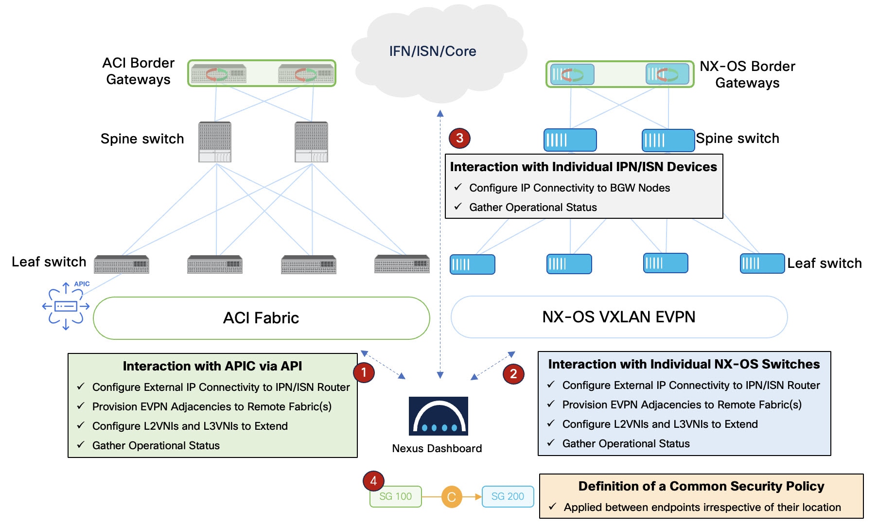
Architectural components
The Nexus One framework relies on these architectural components:
-
Management plane (Nexus Dashboard): The management plane acts as the central controller for the VXLAN-ACI fabric group. It handles the mapping of intents to specific Cisco ACI and Cisco NX-OS configurations.
-
Control plane and data plane interoperability: The system uses Cisco ACI and Cisco NX-OS border gateways to establish the control plane and the data plane between fabrics. The control plane exchanges reachability information through Multiprotocol-Border Gateway Protocol (MP-BGP) EVPN. The data plane provides reachability through VXLAN tunnels.
-
Inter-fabric network (IFN): This is the external routed Layer 3 network that provides the physical underlay connectivity between the Cisco ACI and Cisco NX-OS sites.
-
A "VXLAN-ACI" type of fabric group that manages this specialized VXLAN fabric group across heterogeneous ACI and NX-OS fabrics.
Nexus One topology
The Nexus One architecture uses a model to establish direct Multiprotocol-Border Gateway Protocol (MP-BGP) Ethernet VPN (EVPN) peering between Cisco ACI and Cisco NX-OS fabrics.
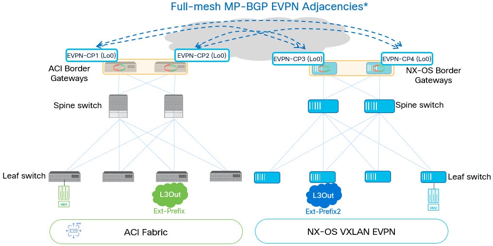
The diagram illustrates these elements:
-
A Nexus Dashboard cluster manages the group.
-
A Cisco ACI fabric has at least one border gateway per pod.
-
Cisco ACI and Cisco NX-OS VXLAN EVPN fabrics use border gateways to establish inter-fabric connectivity.
-
An inter-fabric network (IFN) connects both fabrics.
-
The system establishes logical BGP EVPN peerings directly between Cisco ACI BGWs and Cisco NX-OS BGWs.
Topology and architectural limitations
Observe these topological constraints when you use Nexus One:
-
Multi-cluster fabric group support: VXLAN-ACI fabric groups are restricted to a single Nexus Dashboard cluster. The VXLAN-ACI group type does not support multi-cluster fabric group (although a Nexus Dashboard cluster can be part of a multi-cluster fabric group, a VXLAN-ACI fabric group must reside on a single cluster.).
-
Fabric type restrictions: A VXLAN-ACI fabric group cannot contain Campus VXLAN EVPN fabrics. Use this group type for Data Center VXLAN EVPN and Cisco ACI interoperability.
-
Telemetry requirement: You must enable telemetry for the Cisco ACI fabric during onboarding to support the Nexus One operational model.
Support for adding multi-tenant NX-OS fabrics into VXLAN-ACI fabric groups
Prior to Nexus Dashboard 4.3.1, multi-tenant NX-OS fabrics, which are fabrics with tenants other than default-tenant (named tenants, or a non-default-tenants), were not allowed to be member fabrics in a VXLAN-ACI fabric group. If you wanted to bring those NX-OS fabrics into a VXLAN-ACI fabric group, you had to disassociate those non-default-tenants before you could add that NX-OS fabric as a member fabric in a VXLAN-ACI fabric group.
Beginning in Nexus Dashboard 4.3.1, support is now available for importing an NX-OS fabric into a VXLAN-ACI fabric group even if there are non-default-tenants associated with that NX-OS fabric, and you can then stretch that non-default-tenant and deploy any tenant policies to an ACI fabric after importing the multi-tenant NX-OS fabric into that VXLAN-ACI fabric group.
Note these guidelines and restrictions for adding multi-tenant NX-OS fabrics into VXLAN-ACI fabric groups:
-
Brownfield import is now supported for NX-OS fabrics for non-default-tenants.
-
You cannot remove an NX-OS fabric from a VXLAN-ACI fabric group while app-centric configurations or shared tenant common policies are present. You must first delete those policies before removing the fabric.
-
If any VRF or network is stretched in the border gateway devices of any site, you cannot remove the NX-OS fabric from the VXLAN-ACI fabric group. You have to first unstretch the configuration (networks and VRFs) from the border gateway devices in all sites before you can remove the NX-OS fabric from the VXLAN-ACI fabric group.
Mapping between ND, NX-OS and ACI policies for VXLAN-ACI fabric groups
This table provides mapping information between Nexus Dashboard, NX-OS and ACI policies for VXLAN-ACI fabric groups.
| Nexus Dashboard | NX-OS | ACI |
|---|---|---|
|
VRF |
VRF |
VRF |
|
Network |
Network |
BD, EPG |
|
Network attachment |
Network attachment |
EPG’s static port binding |
|
Security Group |
Security Group |
Endpoint Security Group |
|
Security Contract |
Security Policy Map |
Subject of ACI contract |
|
Protocol definition and protocol definition entry |
Security Class-map and match |
Filter and filter entry |
|
Security association name |
Not used |
ACI contract name |
|
Source of security association |
The source security group in a security association |
Consumer of ACI contract |
|
Destination of security association |
The destination security group in a security association |
Provider of ACI contract |
|
Network selector for security groups that uses a normal network as the selector |
VLAN selector |
EPG selector |
|
Network selector for security groups that uses a child network as the selector |
Port, VLAN selector |
EPG selector |
|
IP selector for security groups |
IP selector |
IP subnet selector |
|
External subnet selector |
External subnet selector |
External subnet selector |
Prerequisites and requirements for Nexus One
To implement the Nexus One architecture and establish interoperability between ACI and Cisco NX-OS fabrics within a VXLAN-ACI fabric group, meet these software, hardware, and system configurations:
Software version requirements
All components in the architecture must run the minimum software versions to support automated inter-fabric connectivity (IFC) and policy mapping:
-
Cisco Nexus Dashboard: Release 4.2.1 or later.
-
Cisco Application Policy Infrastructure Controller (APIC): Release 6.1.4 or later.
-
Cisco NX-OS: Release 10.5(3) or later.
Hardware and connectivity requirements
The physical infrastructure must support border gateway functions and inter-fabric communication.
-
Cisco ACI border gateways (BGWs): At least one border gateway is required in every Cisco ACI pod in the fabric group.
-
Inter-fabric network (IFN): An external Layer 3 network, must interconnect the Cisco ACI and Cisco NX-OS sites.
-
MTU settings: Configure jumbo MTU (9216) on the ISN or IFN switches.
System and fabric settings
Enable specific global and fabric-level settings in Nexus Dashboard to allow for automated discovery and telemetry collection.
-
Telemetry: You must enable telemetry for all Cisco ACI fabrics during onboarding. This is required for Nexus Dashboard to manage Cisco ACI as part of a Nexus One architecture.
-
LLDP link discovery: Enable Link Layer Discovery Protocol (LLDP) discovery in the Nexus Dashboard advanced settings (Admin > System Settings > General > Advanced settings).
-
Monitor mode: When you onboard fabrics of type External Connectivity (used for ISN or IFN switches), disable Monitor Mode to allow Nexus Dashboard to automate underlay and overlay configurations.
-
Fabric group membership: Add the ACI fabric, the external connectivity fabric (ISN or IFN), and the Cisco NX-OS fabrics to the same VXLAN-ACI fabric group to automate underlay and overlay configurations.
Supported switch roles
Nexus Dashboard automates connectivity based on the roles assigned to the switches during onboarding. Assign these supported roles to the switches:
-
For Cisco ACI fabrics:
-
Border gateway: At least one border gateway is required in every Cisco ACI pod.
-
-
For external connectivity fabrics (IFN):
-
Core router
-
Edge router
-
VXLAN-ACI fabric group configuration workflow
Navigate to the Fabric groups page (Manage > Fabrics > Fabric groups) and click the learn more link in VXLAN-ACI fabric groups description in the Fabric groups page to bring up a detailed walkthrough in the Nexus Dashboard GUI of the stages that you must go through to successfully create a VXLAN-ACI fabric group.
Follow these steps to deploy a VXLAN-ACI fabric group:
-
Onboard fabrics (ACI, Cisco NX-OS, ISN): Onboard the ACI fabric through the APIC, the Cisco NX-OS fabric, and the external connectivity inter-switch network (ISN) fabric into Nexus Dashboard. See Onboard ACI fabrics for those procedures.
-
Assign Cisco NX-OS roles: Assign the Border Gateway role to the appropriate switches in the Cisco NX-OS fabric. See Assign switch roles for those procedures.
-
Assign ISN roles: Assign the Core Router or Edge Router role to the switches in the external connectivity (ISN) fabric. See Assign switch roles for those procedures.
-
Create a VXLAN-ACI fabric group: Create a VXLAN-ACI fabric group. Ensure that you add the ACI fabric as the first member. See Create fabric groups for those procedures.
-
Create and associate a tenant: On the Multi-tenancy page, create a tenant and associate it with the VXLAN-ACI fabric group. See Configuring Tenants and Tenant Domains for those procedures.
-
Define and stretch a VRF: Create a VRF instance within the fabric group and stretch it to the ACI and Cisco NX-OS Border Gateways. See Working with VRFs for those procedures.
-
Define and stretch a network: Create a Layer 2 or Layer 3 network and stretch it across the fabric group to enable cross-domain connectivity. See Working with networks for those procedures.
The Layer 2 with VRF option appears only if the Security Groups MAC Segmentation option is enabled in the fabric settings.
-
Create security groups: Define security groups and add network or IP selectors to classify endpoints across the fabrics. See Working with security groups for those procedures.
-
Define protocol definitions: Create protocol definitions to specify the traffic filters, such as TCP, UDP, or ICMP, required for security rules. See Working with protocol definitions for those procedures.
-
Create security contracts: Define security contracts that reference protocol definitions and specify the traffic direction, such as Unidirectional or Bidirectional. See Working with security contracts for those procedures.
-
Establish security associations: Link source and destination security groups through a security association to apply the defined contract. See Working with security associations for those procedures.
-
Perform a tenant deploy: Preview the configuration intent and perform a Tenant Deploy to push all settings to the ACI and Cisco NX-OS fabrics. See Deploying tenants for those procedures.
Create VXLAN-ACI fabric group
Follow these steps to create VXLAN-ACI fabric group.
-
Navigate to Manage > Fabrics > Fabric groups.
-
From the Actions drop-down list, choose Create fabric group.
-
On the Select a type section, perform these actions:
-
Enter the Name.
-
Choose VXLAN from Type section.
-
Choose VXLAN-ACI option from Fabric group type section.
-
-
Click Next.
-
On the Advanced fabric group settings page, perform these actions:
-
General Parameters: Review and update the fields as needed.
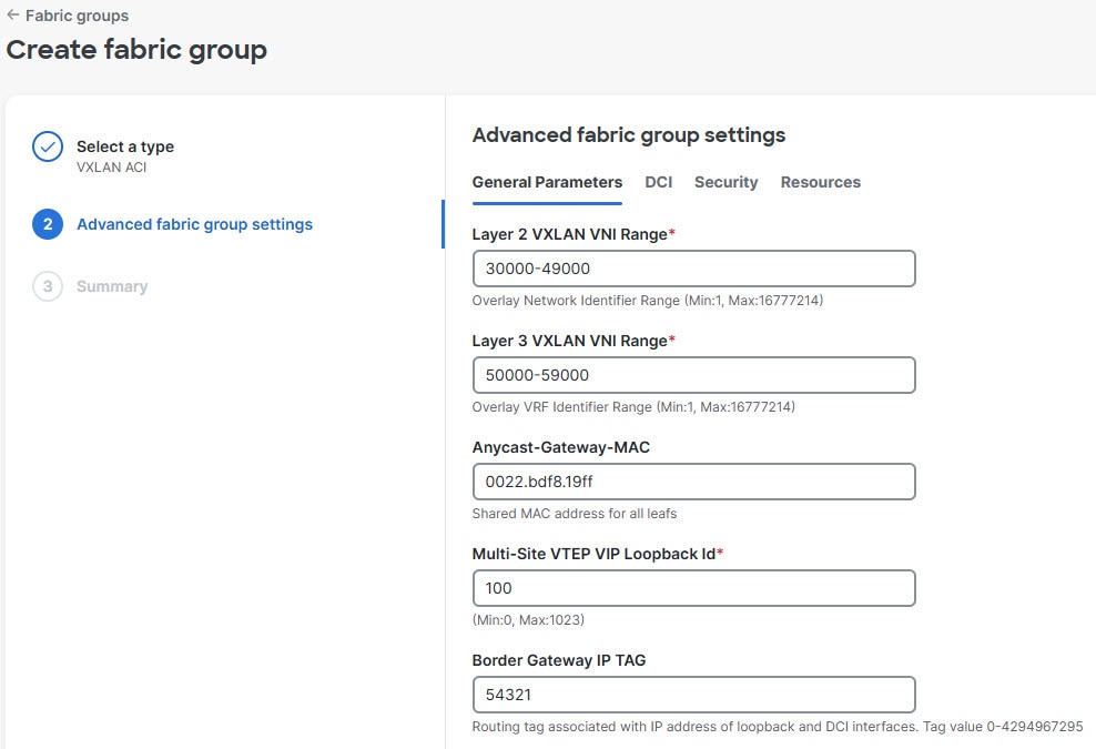
-
Enter the Anycast-Gateway-MAC as 0022.bdf8.19ff.
This address is the default MAC address for the Cisco APIC. Ensure that all Cisco NX-OS member fabrics use this same MAC address to maintain consistency across the VXLAN-ACI fabric group.
-
DCI: We recommend these:
-
Choose directPeering from the Multi-Site Overlay IFC Deployment Method drop-down list.
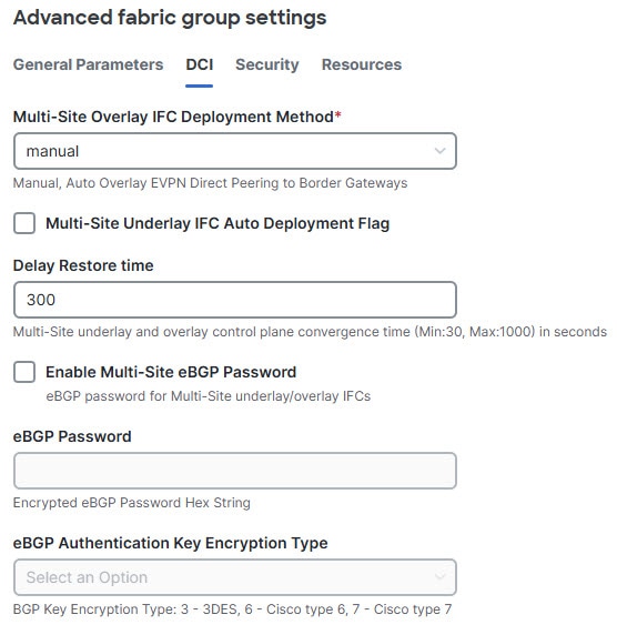
-
Check Multi-Site Underlay IFC Auto Deployment Flag check box.
-
-
Security: Review and update the fields as needed.
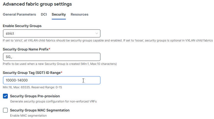
-
Ensure Enable Security Groups option is Strict.
-
Check the Security Groups MAC Segmentation check box. We recommend enabling this feature.
-
-
Resources: Review and update the fields as needed, and then click Next.
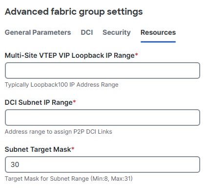
-
-
Review the details on Summary page and click Submit. After successful creation, the Create fabric group page appears.
-
Click Add member fabric.
The Add member fabric page appears.
-
From the Name column, click the ACI fabric. Always add the ACI fabric first.
After successful creation, the Add member fabric page appears with the confirmation message.
-
Click Add another member fabric, to repeat the procedure to add NX-OS fabric and external IFN fabrics.
Guidelines and limitations for VXLAN-ACI fabric groups
-
VXLAN-ACI fabric group restrictions: Observe the following restrictions when managing VXLAN-ACI fabric groups:
-
Nexus Dashboard does not support external Border Gateway Protocol (eBGP) passwords.
-
Add the Cisco ACI fabric as the first member fabric and remove it as the last member fabric.
-
Detach all policies created and owned by Nexus Dashboard and deploy before you remove the Cisco ACI fabric.
-
In Nexus Dashboard 4.2.1, add the Cisco NX-OS fabric to the VXLAN-ACI fabric group before you associate a tenant.
-
In Nexus Dashboard 4.2.1, a fabric group supports a maximum of one Cisco ACI fabric, which can be a multi-pod fabric, and two Cisco NX-OS fabrics.
-
VXLAN-ACI fabric groups do not support multi-cluster fabric groups or one-manage functionality. A VXLAN-ACI fabric group must contain fabrics managed by the same Nexus Dashboard cluster. It cannot span multiple clusters.
-
You cannot change a fabric group sub-type from VXLAN-ACI to VXLAN, nor can you change it from VXLAN to VXLAN-ACI.
-
-
Feature and configuration support:
-
VXLAN-ACI fabric group does not support route servers. In Nexus Dashboard 4.2.1, you must establish full-mesh EVPN adjacencies between the border gateway (BGW) devices in the same fabric group.
-
Nexus Dashboard does not support Layer 3 out (L3Out) configurations for Cisco ACI fabrics.
-
-
VRF policy enforcement: See "Guidelines and limitations: VRFs and VXLAN-ACI fabric groups" in Working with Segmentation and Security for Your Nexus Dashboard VXLAN Fabric for those guidelines.
-
Security policy limitations: See "Guidelines and limitations: Security groups and VXLAN-ACI fabric groups" in Working with Segmentation and Security for Your Nexus Dashboard VXLAN Fabric for those guidelines.
-
Tenant and policy management:
-
Deleting a tenant in Nexus Dashboard does not delete the corresponding tenant in the Cisco Application Policy Infrastructure Controller (APIC).
-
Deleting the last bridge domain (BD) or endpoint security group (ESG) does not delete the application network profile (ANP) in APIC.
-
The system does not support the migration of Cisco ACI Layer 3 out (L3Out) external endpoint groups (External EPGs) to security groups.
-
Policies in one user tenant cannot reference policies from another user tenant.
-
-
Operational and monitoring:
-
The EPG-to-ESG migration workflow does not include a general change-control or ticketing workflow. Snapshot rollback is available as part of the migration lifecycle.
-
Nexus Dashboard does not display faults or anomalies originating from ACI.
-
The Cisco ACI fabric view displays telemetry data streamed directly from the APIC. It does not show configurations in the VXLAN-ACI fabric group that has not been deployed to the APIC.
-
-
Network restrictions for VXLAN-ACI fabric groups: See "Guidelines and limitations: Networks and VXLAN-ACI fabric groups" in Working with Segmentation and Security for Your Nexus Dashboard VXLAN Fabric for those guidelines.
-
Security group MAC segmentation limitations: Observe these limitations for security group MAC segmentation in Nexus Dashboard 4.2.1:
-
Supported fabric types: The security group MAC segmentation feature is supported only for VXLAN-ACI fabric groups.
-
Unsupported configurations: Although the Security Groups MAC Segmentation option is visible on the Security page for all VXLAN fabrics, do not enable it for non-ACI VXLAN fabrics.
-
Functional impact: Enabling this feature on unsupported fabrics allows the creation of ‘Layer 2 with VRF’ networks, which are not supported. This prevents member add/remove operations and causes functional conflicts when using security group loose mode.
-
Recommendation: If you enabled this feature and deployed Layer 2 with VRF networks, remove those networks and disable Security Groups MAC Segmentation in the fabric settings to restore standard functionality.
-
Understanding the process for importing tenant policies from ACI fabrics into VXLAN-ACI fabric groups
This feature provides the ability to migrate endpoint groups (EPGs) on APIC to endpoint security groups (ESGs) using the EPG-to-ESG migration workflow, and import those ESGs, as well as VRFs, bridge domains, and so on, into Nexus Dashboard.
Mapping between ACI and Nexus Dashboard policies
Use the information in this table to understand how ACI components map to Nexus Dashboard components when importing tenant policies from existing ACI fabrics into Nexus Dashboard VXLAN-ACI fabric groups. For a more extensive set of mapping information, see Mapping between ND, NX-OS and ACI policies for VXLAN-ACI fabric groups.
| ACI (before import) | Nexus Dashboard (after import) |
|---|---|
|
Bridge domain (BD) + 1 endpoint group (EPG) (Network-centric design) |
Network (normal) |
|
BD + 2 or more EPGs (Application-centric design) |
Normal network + child networks:
|
|
EPG contract (original EPG contract, pre-migration) |
Security contract |
|
ESG contract |
Security association |
Import tenant policies from ACI fabrics
This section provides information and procedures for importing tenant policies from ACI fabrics into Nexus Dashboard for use with a VXLAN-ACI fabric group.
Guidelines and limitations: Importing tenant policies from ACI fabrics
-
To ensure a successful import of the tenant policies from the ACI fabrics, perform the tasks in the order listed above, which allows for less restrictive name lengths on the tenant policies. Performing the tasks out of order could force more restrictive, shorter name lengths.
-
Using the EPG-to-ESG migration workflow, as described in Use the EPG-to-ESG migration workflow, may be disruptive: either a temporary disruption in communication might occur or, if the migration does not respect the contracts, an impact might be seen on application flows. We recommend that you implement the EPG-to-ESG migration workflow during a maintenance window to minimize issues with any potential disruptions.
-
Migrating the EPGs on the ACI fabric to ESGs using the EPG-to-ESG migration workflow will cause traffic disruptions because the pcTag associated to the classified resources will change as part of the process. If you do not want to have that traffic impact, you can temporarily "open up" the security policies in a VRF by creating a vzAny-to-vzAny permit-all contract.
-
ACI contracts should have only one subject. When importing tenant policies from ACI fabrics, Nexus Dashboard only supports importing ACI contracts with one subject.
-
You must enable a global AES strong encryption key in the ACI fabric before going through the snapshot creation step in the EPG-to-ESG migration workflow. This setting is necessary so that APIC uses the key to encrypt secure fields, such as passwords. Refer to Encrypting Configuration Files Using the GUI in the appropriate Cisco APIC Basic Configuration Guide for those procedures.
Additional important information
These sections provide additional important information that is helpful when you go through the process of importing tenant policies from ACI fabrics.
Object name-length limits and automatic name shortening
When Nexus Dashboard generates the migration plan, each ESG, security association (contract clone), and Nexus Dashboard contract name is checked against a maximum length. Because Nexus Dashboard adds a tenant prefix to imported objects, the prefix consumes part of the budget for some object types. Generated names that would exceed the limit are shortened automatically, which allows for the analysis to succeed without manual intervention.
The migration plan applies the following limits:
-
The ESG name (stored in the ESG name field of the plan) has a maximum length of 61 characters, which includes the tenant prefix. When the tenant prefix length is 10 (the default fallback), the effective maximum for the ESG name itself is 52 characters.
-
The security-association name for each contract clone (the cloneName field of the plan) has a maximum length of 64 characters. The tenant prefix is not counted against this limit, so the effective maximum remains 64 characters regardless of the tenant prefix length.
-
The Nexus Dashboard contract name (the ndContractName field of the plan) has a maximum length of 38 characters, which includes the tenant prefix. When the tenant prefix length is 10 (the default fallback), the effective maximum for the Nexus Dashboard contract name itself is 29 characters.
-
For object types where the tenant prefix is counted, the effective maximum is computed as the total maximum (the tenant prefix length + 1). The "+1" accounts for the tenant/policy-name delimiter, which does not consume budget. The tenant prefix length comes from the per-tenant fabric configuration; when none is configured, Nexus Dashboard uses a fallback of 10 characters.
Shortened ndContractName: Each cloned ESG contract carries two related names in the migration plan:
-
cloneName: The security-association name (bounded by the 64-character security-association limit) -
ndContractName: The Nexus Dashboard contract policy name as it will appear in Nexus Dashboard (bounded by the 38-character Nexus Dashboard-contract limit, with the tenant prefix counted)
Nexus Dashboard seeds ndContractName from the original ACI contract name. If that name would exceed the effective Nexus Dashboard-contract budget, Nexus Dashboard shortens it by preserving the leading portion of the original, truncating the middle, and appending a deterministic 4-character hash of the full original name. The hash makes the shortening reproducible — a given source contract always produces the same shortened name — and prevents collisions when two original contracts share the same leading characters. Any prefix or suffix configured for ESG contract naming during the Create the migration record and APIC snapshot steps is preserved in the shortened result.
Verifying a shortened name: To identify the source of a shortened ndContractName, read the cloneFromDn field of the same contract clone entry in the migration plan; it preserves the full distinguished name of the original ACI contract even after shortening. Final names — shortened or not — also appear in the Map EPGs to ESGs and Review ESG contracts steps and in the Bulk edit YAML downloaded during analysis, so you can confirm them before proceeding to Conversion. If you edit a name in the Bulk edit YAML, keep it within the maximums listed above; otherwise, Nexus Dashboard re-shortens the value or rejects the upload during validation.
Inter-VRF global contracts and automatic scope expansion
If an endpoint group (EPG) or external EPG in one of the selected VRFs consumes or provides an inter-VRF global contract, the corresponding provider or consumer may reside in a VRF that you did not choose. Converting only one side of that relationship would leave broken contract references in the resulting ESG-based configuration, so Nexus Dashboard treats the selection as incomplete.
Before the migration plan is generated, Nexus Dashboard analyzes inter-VRF contract relationships across the in-scope tenants. If one side of an inter-VRF global contract is missing from your selection, Nexus Dashboard automatically adds the missing VRF or VRFs to the selection so that all VRFs that participate in the same contract are migrated together. The Select tenants/VRFs step then updates the VRF list to show both the VRFs that you originally selected and the VRFs that were added automatically.
Review the updated VRF list, including any VRFs that Nexus Dashboard added automatically, before you continue.
TCAM utilization and conversion mode
The migration workflow uses each leaf node’s policy TCAM utilization — measured by APIC as a 5-minute moving average — to choose between two conversion modes and, when utilization is too high, to block the conversion entirely. The check is applied per leaf node. A VRF inherits the highest TCAM band of any leaf node on which it is deployed, and the conversion mode is then selected globally from the worst band of any VRF included in the conversion scope.
-
Below 50% TCAM utilization: All in-scope VRFs are deployed on nodes with healthy TCAM. Conversion runs in TCAM non-optimized mode (ESG contract mappings are installed before EPG and external-EPG selectors). This temporarily uses additional TCAM during migration but minimizes traffic loss because contracts are in place before endpoints reclassify into ESGs.
-
Between 50% and 80% TCAM utilization: At least one node on which an in-scope VRF is deployed is in the warning band. Conversion proceeds, but it runs in TCAM optimized mode (EPG and external-EPG selectors are installed before ESG contract mappings). This conserves TCAM during migration, but you might see additional transient traffic loss while contracts are still being applied. The workflow lists the affected nodes and VRFs as warnings during the Analysis phase in the migration process.
-
At or above 80% TCAM utilization: At least one node on which an in-scope VRF is deployed is in the critical band. The workflow blocks the conversion and lists the critical nodes and VRFs so that you can identify the cause. To proceed, free TCAM on the affected nodes — for example, by removing unused contracts, filters, or rules — or remove the affected VRFs from the conversion scope and run the analysis again. The conversion remains blocked while any in-scope VRF is deployed on a leaf node at or above 80% TCAM utilization, and re-running the conversion without changing either the TCAM state or the conversion scope produces the same critical outcome.
TCAM utilization is sampled during the Analysis phase so that warning and critical conditions are visible before you reach the Conversion phase, and the same check is repeated in the Conversion phase before deployment so that recent changes in TCAM utilization are not missed.
For detailed information about TCAM-related migration behavior in the underlying ESG Migration Assistant process, see the Cisco APIC Security Configuration Guide, Release 6.2(x).
To review TCAM information in Nexus Dashboard:
-
Navigate to Analyze > Analysis Hub > Conformance > Scale.
-
In the Scale conformance last 6 months area, click Switch level, then, under All scale metrics > Fabrics, click on an entry in the ACI fabric in the Switch metrics conformance column.
-
In the Switch Scalability Metrics on Fabric aci-fabric-name page, look for information that contains TCAM in the Metric column (enter
Metric contains TCAMin the filter results field).
Because the underlying APIC measurement is a 5-minute average, transient TCAM spikes may not be reflected immediately, and TCAM that you free up on a node is not reflected in the workflow’s view until the next 5-minute sample is published.
Deleting a migration
Use Delete migration when you want to permanently remove a migration record and the per-migration state that Nexus Dashboard tracks. Delete is appropriate for migration records that were created in error, that you no longer intend to run, or that you have completed and verified and no longer need for audit purposes.
Delete operates on the migration record, not on the migrated configuration. It does not undo any ESG, contract, or selector changes that Conversion has already applied to APIC, and it does not restore the APIC fabric to an earlier configuration. If you want to revert the APIC fabric, perform a snapshot rollback before you delete the migration. After a successful delete, the migration cannot be recovered, and the rollback snapshots associated with that migration are no longer reachable from Nexus Dashboard. See About snapshot rollback for more information.
What delete affects: When delete completes successfully, Nexus Dashboard performs the following on the migration record and its associated artifacts, in this order:
-
On APIC, Nexus Dashboard requests deletion of each configuration snapshot that the migration created. Snapshot deletion is best-effort: if APIC is unreachable or rejects the request for an individual snapshot, that snapshot file remains on APIC and the migration delete continues. You can remove residual snapshot files manually on APIC if they are no longer needed.
-
In Nexus Dashboard, the migration record is removed, along with all child state: phase data, per-VRF analysis output, deployment results, cleanup results, status, and the migration’s tracked snapshot metadata.
-
On the helper component, the per-migration artifact directory (analysis output, cleanup plan, and similar generated files) is removed. This step is best-effort and does not affect the success of the delete.
When a delete is allowed or rejected: Delete is rejected when an operation is currently in progress for the migration record — for example, analysis, deployment, cleanup, or rollback. Wait for the operation to complete or fail before you delete. A migration record in any other state, including pending, successful, and failed, can be deleted.
Force delete: A force option is available for every migration scenario, but is necessary for migration records that are stuck in the in-progress state because of an earlier helper or APIC failure. Force delete bypasses the in-progress check and removes the migration record in the same way as a normal delete. Use force delete only when you are certain that no operation is actively running for the migration, because deleting a record while an operation is genuinely in flight can leave the APIC fabric in a partial state. After a force delete, verify the APIC fabric state against the most recent successful snapshot for that migration; if one exists, reconcile any differences manually or by means of a separate rollback.
How to delete a migration: To delete a migration:
-
In the EPG to ESG migration page for the member ACI fabric, locate the migration record.
-
From the Actions menu, choose Delete migration.
-
Confirm the action when prompted.
Nexus Dashboard performs the snapshot, record, and artifact cleanup described above and displays the result. The delete action is also recorded in the Nexus Dashboard audit log under the migration’s name and fabric.
What is preserved or deleted: Tenants, VRFs, ESGs, contracts, contract clones, selectors, and any other APIC objects created or modified by the migration remain in place after the migration record is deleted. The same applies to objects that were not part of the migration scope. Delete only removes Nexus Dashboard’s record of the migration workflow itself.
Restriction of one active migration per VRF
Each VRF on an ACI fabric can be a member of at most one migration that has not yet reached the successful terminal state. While a migration is still pending, in progress, or failed, the VRFs assigned to it remain reserved for that migration, and Nexus Dashboard prevents the same VRF from being included in any other migration on the same fabric. The reservation is released only in these conditions:
-
When the migration completes successfully and reaches the terminal Successful state
-
When the migration is deleted
-
When the migration is rolled back to the Analysis target (which clears the migration’s tenant and VRF selection entirely)
The constraint is enforced per fabric. A VRF with the same tenant name and VRF name on a different ACI fabric is a different VRF for migration purposes and is not affected.
Nexus Dashboard checks for VRF conflicts in two places during Phase 1: Analysis:
-
When you submit the tenant and VRF selection in the Select tenants/VRFs step. If any selected VRF is already a member of another active migration on the same fabric, the submission is rejected before analysis runs. The workflow displays the conflicting VRFs grouped by tenant and by the migration that already owns them, with instructions to complete, delete, or roll back the conflicting migration before selecting the VRF again. The migration record remains at the Select tenants/VRFs step; the analysis is not started.
-
When Nexus Dashboard automatically expands the migration scope to include a VRF on the other side of an inter-VRF global contract (see Inter-VRF global contracts and automatic scope expansion for more information). If the auto-added VRF is already a member of another active migration on the same fabric, the analysis cannot complete, and Nexus Dashboard returns the migration record to the Select tenants/VRFs step with the message that the required VRF dependencies could not be automatically selected because they are already included in active migrations. Delete or complete the migration that owns the required VRFs and run analysis again.
Resolving a VRF conflict: When a conflict is reported, choose one of the following actions on the migration that currently owns the conflicting VRFs:
-
Complete the migration: Drive it through Conversion and Cleanup to the Successful terminal state. Successful migrations release their VRFs immediately.
-
Delete the migration: Delete is the right action when the other migration is no longer needed or was created in error. See Deleting a migration for more information.
-
Roll back the migration to the Analysis target: An Analysis-target rollback clears the migration’s tenant and VRF selection, which releases all VRFs that the migration was holding. Rolling back to Conversion or Cleanup does not release the VRFs, because the migration’s tenant and VRF selection is preserved across those rollbacks. See About snapshot rollback for more information.
After the conflict is resolved on the other migration, retry the Select tenants/VRFs step, or, when the conflict was triggered by auto-expansion, retry analysis. Nexus Dashboard rechecks the constraint each time and proceeds when the conflict has cleared.
About snapshot rollback
Snapshot rollback is available as part of the migration lifecycle. Use rollback when you need to return the migration to a previously captured state after a migration step has been performed.
During the migration workflow, APIC snapshots are created at key stages such as Analysis, Conversion, and Cleanup. These snapshots provide recovery points that you can use if you need to revert changes after reviewing the migration outcome or after identifying an issue during a maintenance window.
Preserve the snapshot created at the beginning of each phase until you have verified the results of that phase. If a problem is identified during conversion or cleanup, use the APIC built-in configuration rollback capability to return to the appropriate snapshot before continuing with additional migration actions.
For detailed information about rollback behavior and verification guidance for the underlying ESG Migration Assistant process, see the Cisco APIC Security Configuration Guide, Release 6.2(x).
Snapshot rollback returns both sides of the migration to a previously captured point in a single action:
-
On APIC, Nexus Dashboard restores the fabric configuration from the snapshot associated with the target phase. The restore is an atomic, replace-style import of the snapshot file, so the resulting APIC state is identical to the state captured when that snapshot was taken.
-
In Nexus Dashboard, the migration record is reverted to the start of the target phase. The current phase, current operation, per-VRF status, and per-VRF counts are all reset to the values that were applied when that phase began, and any data, snapshots, and per-VRF results accumulated after the target phase are deleted.
Use rollback when, after reviewing the outcome of a migration step, you decide to revert that step before continuing. Because rollback affects the APIC fabric as well as the migration record, perform it during a maintenance window when possible.
Snapshots that are eligible as rollback targets: During the migration workflow, Nexus Dashboard creates three APIC configuration snapshots, one at the start of each phase. The snapshot is the rollback point for that phase:
-
The Analysis snapshot is created in Phase 1: Analysis, in the Create APIC snapshot step. Rolling back to Analysis returns the APIC fabric to the state captured before the migration plan was generated, and resets the migration record so that no tenants or VRFs are selected and no grouping strategy or editing mode is chosen. After the rollback, you must re-run the Select tenants/VRFs and Select grouping strategy steps.
-
The pre-conversion snapshot is created in Phase 2: Conversion, in the Create APIC snapshot step. Rolling back to Conversion returns the APIC fabric to the state captured before the ESG and contract changes were deployed, and resets the migration record so that the conversion can be reviewed and deployed again. The original tenant and VRF selection from Analysis is preserved, but per-VRF deployment and conversion results are cleared.
-
The pre-cleanup snapshot is created in Phase 3: Cleanup, in the Create APIC snapshot step. Rolling back to Cleanup returns the APIC fabric to the state captured before legacy EPG-based policy artifacts were removed, and resets the migration record so that the cleanup review and execution can be repeated. The original tenant and VRF selection is preserved, and per-VRF cleanup results are cleared.
When rollback is allowed: Rollback can be started from the migration record only when all of the following are true:
-
The migration record exists and is not in a terminal phase.
-
No operation is currently in progress for the migration record. If a phase action such as analysis, deployment, or cleanup is running, wait for it to complete or fail before starting rollback.
-
The selected target phase is at or before the current phase of the migration record. Rolling forward is not supported.
When any of these conditions is not met, Nexus Dashboard rejects the rollback request and the migration record state is left unchanged.
If a period of time has passed between the point that you went through a migration workflow and the point when you decide to perform a rollback, be aware of any changes that might have been made on the APIC side in that timeframe before performing a rollback. For example, if snapshots were taken during a particular migration workflow, and then you decide to perform a rollback at a later date using a snapshot from that earlier migration workflow, verify that changes have not been made on the APIC side during that timeframe because you might lose any configurations that were made in that timeframe when you perform the rollback.
How to perform a rollback: To perform a rollback:
-
In the EPG to ESG migration page for the member ACI fabric, open the migration record.
-
From the Actions menu, choose the rollback action for the desired target phase.
Nexus Dashboard lists the rollback snapshots that exist for that phase; select the snapshot to use. Nexus Dashboard then performs the APIC configuration restore and, when it completes successfully, applies the migration-record reset for that phase.
Rollback runs as a single operation on the migration record. While it is running, the record is marked in progress and no other phase action can be started against it.
What happens after a successful rollback: When rollback succeeds:
-
The APIC fabric configuration matches the snapshot you selected.
-
The migration record’s current phase is set to the target phase, its status is set to pending, and its current operation is set to the Create APIC snapshot step of the target phase. You are positioned to repeat the phase from its first step, including taking a new snapshot.
-
All snapshots that were created after the target phase are deleted from the migration record. The corresponding APIC snapshot files are not deleted automatically; you can remove them from APIC if they are no longer needed.
-
All migration-record data captured for phases after the target phase is deleted, including per-VRF analysis output, deployment results, and cleanup results.
-
For an Analysis-target rollback only, the tenant and VRF selection and the grouping strategy are also cleared. You must re-select them before proceeding.
What happens if rollback fails: If the APIC configuration restore does not succeed, Nexus Dashboard marks the migration record as failed and records the error returned by APIC. The migration record’s current phase is left at its pre-rollback value so that you can inspect the prior state. To recover, address the underlying APIC condition reported in the error, then either retry the rollback to the same target phase or open the migration record and use Resume to continue from the pre-rollback phase. Snapshots and migration-record data are not deleted on a failed rollback.
Per-fabric restriction on operations that actively modify the ACI fabric
In addition to the per-VRF restriction described in Restriction of one active migration per VRF, Nexus Dashboard enforces a per-fabric restriction on operations that actively modify the ACI fabric. For a given ACI fabric, at most one migration on that fabric can have any of the following operations in progress at the same time:
-
A Conversion deploy in the Deploy ESG & clone contracts step or the Conversion step of Phase 2: Conversion,
-
a cleanup execution in the Cleanup step of Phase 3: Cleanup, or
-
a snapshot rollback that is targeting Conversion, Cleanup, or any later phase of the migration record.
The restriction applies even when the migrations have non-overlapping tenant and VRF scopes because each of these operations changes the APIC fabric state that is shared across migration records.
The restriction does not apply to Phase 1: Analysis. Multiple migrations on the same fabric can run Analysis simultaneously, subject to the per-VRF restriction. The restriction also does not apply to snapshot creation, plan editing, or any other read-only step in the workflow.
Nexus Dashboard checks the restriction immediately before it starts a deploy, cleanup, or rollback. If another migration on the same fabric already has one of those operations in progress:
-
The new request is rejected,
-
the migration record is left in its current state with no operation started, and
-
Nexus Dashboard returns a message that names the operation that is in progress and the migration record that owns it.
Wait for the in-progress operation to finish or fail before you retry the rejected operation. If you need to stop the in-progress operation rather than wait for it, complete or roll back that migration first, then retry.
The restriction is per-fabric. A migration on a different ACI fabric is not affected, and operations on different fabrics can proceed concurrently.
Examples of Bulk edit YAML files
At a certain point in the Phase 1: Analysis stage of the EPG-to-ESG migration workflow, you will be given the option to Bulk edit the migration plan as a YAML file. Following are examples of Bulk edit YAML files for your reference.
vrfs:
    - vrf: uni/tn-foo/ctx-vrf-1
      esgs:
        - name: ESG_foo_ap-1_1
          applicationProfile: ap-1
          epgs:
            - uni/tn-foo/ap-ap-1/epg-epg-1
            - uni/tn-foo/ap-ap-1/epg-epg-3
          prov:
            - uni/tn-foo/brc-ct-1
          cons: []
        - name: ESG_foo_ap-1_2
          applicationProfile: ap-1
          epgs:
            - uni/tn-foo/ap-ap-1/epg-epg-2
            - uni/tn-foo/ap-ap-1/epg-epg-4
          prov: []
          cons:
            - uni/tn-foo/brc-ct-1
        - name: ESG_foo_ap-1_3
          applicationProfile: ap-1
          epgs:
            - uni/tn-foo/ap-ap-1/epg-epg-5
            - uni/tn-foo/ap-ap-1/epg-epg-7
          prov:
            - uni/tn-foo/brc-ct-2
          cons: []
        - name: ESG_foo_ap-1_4
          applicationProfile: ap-1
          epgs:
            - uni/tn-foo/ap-ap-1/epg-epg-6
            - uni/tn-foo/ap-ap-1/epg-epg-8
          prov: []
          cons:
            - uni/tn-foo/brc-ct-2
      leakInternalSubnets: []
      leakExternalPrefixes: []
contractClones:
    - cloneName: ct-1_e_1
      cloneFromDn: uni/tn-foo/brc-ct-1
      ndContractName: ct-1
      providerESG: uni/tn-foo/ap-ap-1/esg-ESG_foo_ap-1_1
      consumerESG: uni/tn-foo/ap-ap-1/esg-ESG_foo_ap-1_2
    - cloneName: ct-2_e_1
      cloneFromDn: uni/tn-foo/brc-ct-2
      ndContractName: ct-2
      providerESG: uni/tn-foo/ap-ap-1/esg-ESG_foo_ap-1_3
      consumerESG: uni/tn-foo/ap-ap-1/esg-ESG_foo_ap-1_4
contractIfClones: []
vrfs:
    - vrf: uni/tn-foo/ctx-vrf-1
      esgs:
        - name: esg-1
          applicationProfile: ap-1
          epgs:
            - uni/tn-foo/ap-ap-1/epg-epg-1
          prov:
            - uni/tn-foo/brc-ct-1
          cons: []
        - name: esg-2
          applicationProfile: ap-1
          epgs:
            - uni/tn-foo/ap-ap-1/epg-epg-2
          prov: []
          cons:
            - uni/tn-foo/brc-ct-1
        - name: esg-3
          applicationProfile: ap-1
          epgs:
            - uni/tn-foo/ap-ap-1/epg-epg-3
          prov:
            - uni/tn-foo/brc-ct-1
          cons: []
        - name: esg-4
          applicationProfile: ap-1
          epgs:
            - uni/tn-foo/ap-ap-1/epg-epg-4
          prov: []
          cons:
            - uni/tn-foo/brc-ct-1
        - name: esg-5
          applicationProfile: ap-1
          epgs:
            - uni/tn-foo/ap-ap-1/epg-epg-5
          prov:
            - uni/tn-foo/brc-ct-2
          cons: []
        - name: esg-6
          applicationProfile: ap-1
          epgs:
            - uni/tn-foo/ap-ap-1/epg-epg-6
          prov: []
          cons:
            - uni/tn-foo/brc-ct-2
        - name: esg-7
          applicationProfile: ap-1
          epgs:
            - uni/tn-foo/ap-ap-1/epg-epg-7
          prov:
            - uni/tn-foo/brc-ct-2
          cons: []
        - name: esg-8
          applicationProfile: ap-1
          epgs:
            - uni/tn-foo/ap-ap-1/epg-epg-8
          prov: []
          cons:
            - uni/tn-foo/brc-ct-2
      leakInternalSubnets: []
      leakExternalPrefixes: []
contractClones:
    - cloneName: ct-1_e_1
      cloneFromDn: uni/tn-foo/brc-ct-1
      ndContractName: ct-1
      providerESG: uni/tn-foo/ap-ap-1/esg-esg-1
      consumerESG: uni/tn-foo/ap-ap-1/esg-esg-2
    - cloneName: ct-1_e_2
      cloneFromDn: uni/tn-foo/brc-ct-1
      ndContractName: ct-1
      providerESG: uni/tn-foo/ap-ap-1/esg-esg-1
      consumerESG: uni/tn-foo/ap-ap-1/esg-esg-4
    - cloneName: ct-1_e_3
      cloneFromDn: uni/tn-foo/brc-ct-1
      ndContractName: ct-1
      providerESG: uni/tn-foo/ap-ap-1/esg-esg-3
      consumerESG: uni/tn-foo/ap-ap-1/esg-esg-2
    - cloneName: ct-1_e_4
      cloneFromDn: uni/tn-foo/brc-ct-1
      ndContractName: ct-1
      providerESG: uni/tn-foo/ap-ap-1/esg-esg-3
      consumerESG: uni/tn-foo/ap-ap-1/esg-esg-4
    - cloneName: ct-2_e_1
      cloneFromDn: uni/tn-foo/brc-ct-2
      ndContractName: ct-2
      providerESG: uni/tn-foo/ap-ap-1/esg-esg-7
      consumerESG: uni/tn-foo/ap-ap-1/esg-esg-6
    - cloneName: ct-2_e_2
      cloneFromDn: uni/tn-foo/brc-ct-2
      ndContractName: ct-2
      providerESG: uni/tn-foo/ap-ap-1/esg-esg-7
      consumerESG: uni/tn-foo/ap-ap-1/esg-esg-8
    - cloneName: ct-2_e_3
      cloneFromDn: uni/tn-foo/brc-ct-2
      ndContractName: ct-2
      providerESG: uni/tn-foo/ap-ap-1/esg-esg-5
      consumerESG: uni/tn-foo/ap-ap-1/esg-esg-6
    - cloneName: ct-2_e_4
      cloneFromDn: uni/tn-foo/brc-ct-2
      ndContractName: ct-2
      providerESG: uni/tn-foo/ap-ap-1/esg-esg-5
      consumerESG: uni/tn-foo/ap-ap-1/esg-esg-8
contractIfClones: []
vrfs:
    - vrf: uni/tn-tn-apic-94-11/ctx-vrf-1
      esgs:
        - name: esg-1
          applicationProfile: ap-1
          epgs:
            - uni/tn-tn-apic-94-11/ap-ap-1/epg-epg-1
          prov:
            - uni/tn-tn-apic-94-11/brc-ct-icmp
            - uni/tn-tn-apic-94-11/brc-ct-web
          cons: []
      leakInternalSubnets: []
      leakExternalPrefixes: []
    - vrf: uni/tn-tn-apic-94-11/ctx-vrf-2
      esgs:
        - name: esg-2
          applicationProfile: ap-1
          epgs:
            - uni/tn-tn-apic-94-11/ap-ap-1/epg-epg-2
          prov:
            - uni/tn-tn-apic-94-11/brc-ct-https
          cons:
            - uni/tn-tn-apic-94-11/brc-ct-web
      leakInternalSubnets: []
      leakExternalPrefixes: []
    - vrf: uni/tn-tn-apic-94-11/ctx-vrf-3
      esgs:
        - name: esg-3
          applicationProfile: ap-1
          epgs:
            - uni/tn-tn-apic-94-11/ap-ap-1/epg-epg-3
          prov: []
          cons:
            - uni/tn-tn-apic-94-11/brc-ct-https
            - uni/tn-tn-apic-94-11/brc-ct-icmp
      leakInternalSubnets: []
      leakExternalPrefixes: []
contractClones:
    - cloneName: ct-https_e_1
      cloneFromDn: uni/tn-tn-apic-94-11/brc-ct-https
      ndContractName: ct-https
      providerESG: uni/tn-tn-apic-94-11/ap-ap-1/esg-esg-2
      consumerESG: uni/tn-tn-apic-94-11/ap-ap-1/esg-esg-3
    - cloneName: ct-icmp_e_1
      cloneFromDn: uni/tn-tn-apic-94-11/brc-ct-icmp
      ndContractName: ct-icmp
      providerESG: uni/tn-tn-apic-94-11/ap-ap-1/esg-esg-1
      consumerESG: uni/tn-tn-apic-94-11/ap-ap-1/esg-esg-3
    - cloneName: ct-web_e_1
      cloneFromDn: uni/tn-tn-apic-94-11/brc-ct-web
      ndContractName: ct-web
      providerESG: uni/tn-tn-apic-94-11/ap-ap-1/esg-esg-1
      consumerESG: uni/tn-tn-apic-94-11/ap-ap-1/esg-esg-2
contractIfClones: []
vrfs:
    - vrf: uni/tn-coke/ctx-vrf-coke-2
      esgs:
        - name: ESG_instp-vrf-coke-2
          applicationProfile: l3out-vrf-coke-2
          epgs:
            - uni/tn-coke/out-l3out-vrf-coke-2/instP-instp-vrf-coke-2
          externalSubnets:
            - ip: 0.0.0.0/16
              scope: private
          prov:
            - uni/tn-coke/brc-ctr-new
          cons: []
      leakInternalSubnets: []
      leakExternalPrefixes: []
    - vrf: uni/tn-coke/ctx-vrf-coke
      esgs:
        - name: esg-coke-2
          applicationProfile: anp-coke
          preExisting: true
          epgs: []
          prov: []
          cons: []
      leakInternalSubnets: []
      leakExternalPrefixes: []
contractClones:
    - cloneName: ctr-new_e_1
      cloneFromDn: uni/tn-coke/brc-ctr-new
      ndContractName: ctr-new
      providerESG: uni/tn-coke/ap-l3out-vrf-coke-2/esg-ESG_instp-vrf-coke-2
      consumerESG: uni/tn-coke/ap-anp-coke/esg-esg-coke-2
contractIfClones: []
Understanding ACI fabric configurations that are skipped during the import process
When you start the process of importing tenant policies from ACI, as described in Import tenant policies from ACI into Nexus Dashboard, certain policies might not be compatible with Nexus Dashboard. In those situations, Nexus Dashboard skips those policies during the import process and imports only the supported policies. When this happens, a message is displayed with this information:
-
The policies that were skipped during import,
-
the reason each policy was skipped, and
-
the actions required for you to make the policies compatible and successfully import them into Nexus Dashboard.
These are examples of situations where an ACI fabric configuration might be skipped during the import process:
-
Objects that are created by default in APIC but are not eligible for import (for example, the
defaultandcopyVRFs in tenant-common) -
Preferred groups that are enabled on VRF
-
Object names that exceed the Nexus Dashboard maximum length after tenant prefixing
-
Subnet scopes that are not Nexus Dashboard-compatible
-
Subnets with prefix length of /32 or /128
-
Contracts with more than one subject
-
Contracts that have more than one consumer or one provider
-
Contracts that have missing consumer or provider
-
Contracts that have consumer interface
-
Consumer or provider other than ESG or vzAny
-
Consumer, provider, and contract not in same tenant
-
Consumer and provider are in different VRF
-
ESG with intra-isolation enabled
-
Unsupported selectors in ESG (for example: Tag Selector)
Create the VXLAN-ACI fabric group and associate fabrics
In Nexus Dashboard:
-
If the ACI fabric is not already added to Nexus Dashboard, onboard it to Nexus Dashboard using multi-cluster connectivity.
See Connecting Clusters for more information.
-
Create the fabric group and associate the fabrics.
You will import tenant policies from ACI fabrics and you will integrate both ACI and NX-OS fabrics into a single VXLAN-ACI fabric group. For more information, see Creating Fabrics and Fabric Groups.
-
Create a VXLAN-ACI fabric group.
-
Add the ACI and VXLAN fabrics to the VXLAN-ACI fabric group in the correct order.
You must add the ACI and VXLAN fabrics to the VXLAN-ACI fabric group in this order:
-
First, add the ACI fabric to the new VXLAN-ACI fabric group.
-
Then add the VXLAN fabric to the new VXLAN-ACI fabric group.
-
-
What’s next: Import tenants from ACI into Nexus Dashboard.
Import tenants from ACI into Nexus Dashboard
Use these procedures to create an ACI tenant in Nexus Dashboard and associate the tenant to the ACI fabric.
Because the ACI fabric is a member of the VXLAN-ACI fabric group, these procedures associate the tenant to the VXLAN-ACI fabric group as well.
In Nexus Dashboard:
-
Import the first tenant from ACI into Nexus Dashboard.
-
Follow the procedures provided in the "Import a tenant from ACI" section in Configuring Tenants and Tenant Domains to complete this task.
Enter these values in this procedure:
-
Fabric: Choose the ACI fabric that you added to the VXLAN-ACI fabric group in Create the VXLAN-ACI fabric group and associate fabrics.
-
ACI tenants on fabric: Choose the first tenant from ACI that you want to import into Nexus Dashboard.
-
-
Enter the necessary values for the remaining fields in the Import tenant (ACI) page, then click Save.
-
-
Repeat this step to import the remaining tenants from ACI into Nexus Dashboard, if necessary.
Once you have imported all the necessary tenants from ACI into Nexus Dashboard, navigate into the VXLAN-ACI fabric group and click Segmentation and security > Tenants to verify that all of the imported tenants are associated with this fabric group.
What’s next: Use the EPG-to-ESG migration workflow.
Use the EPG-to-ESG migration workflow
Beginning with Nexus Dashboard Release 4.3.1, you can migrate endpoint groups (EPGs) in a Cisco ACI fabric to endpoint security groups (ESGs) by using an integrated workflow in Nexus Dashboard for VXLAN-ACI fabric groups. This workflow provides a guided Nexus Dashboard experience for the ESG Migration Assistant process that is available in Cisco APIC.
The migration workflow is organized into Analysis, Conversion, and Cleanup phases. These phases help you define the migration scope, review the proposed ESG-based configuration, apply the required changes, and remove obsolete EPG-related artifacts after conversion is complete.
Outside the phase flow, the migration lifecycle also supports migration-level actions such as starting a migration, resuming a migration, and rolling back to an earlier snapshot when needed. Previews are also available at various stages during the deploy, conversion, and cleanup stages to verify the payload being pushed to the ACI fabric as a part of those operations.
For detailed information about the underlying ESG Migration Assistant behavior, see the Cisco APIC Security Configuration Guide, Release 6.2(x).
EPG-to-ESG migration phases in Nexus Dashboard
The EPG-to-ESG migration workflow is available in ACI fabrics that are members of the VXLAN-ACI fabric group under Segmentation and security > EPG to ESG migration. Nexus Dashboard uses a phased workflow so that you can review the migration scope, validate the proposed changes, and proceed in a controlled manner.
The workflow is organized into three phases:
-
Analysis, which corresponds to the migration assistant analysis or dry-run stage.
-
Conversion, which applies the reviewed migration plan.
-
Cleanup, which removes obsolete legacy policy artifacts after conversion is complete.
Tenant policy import is not part of the ESG Migration Assistant phase flow. Treat it as a separate post-migration task after you have completed and verified the migration workflow.
Complete migration verification and any required rollback decisions before you begin tenant policy import.
These phases describe the guided migration workflow in Nexus Dashboard. Additional lifecycle actions, such as resume and snapshot rollback, are available from the migration context outside the phase sequence.
-
As you proceed through the three phases, click the Learn more link in the upper right corner to get additional information about what happens in each phase of the migration process.
-
If you navigate away from the EPG-to-ESG migration workflow at any point during the migration process, you can return to the migration and resume your EPG-to-ESG migration workflow by navigating back to the EPG to ESG migration page in the ACI fabric, then choosing your migration workflow and clicking Actions > Resume.
Phase 1: Analysis
Use the Analysis phase to create the migration record, capture the initial APIC state, choose the migration strategy, and review the proposed EPG-to-ESG mappings and ESG contract relationships before proceeding to the Conversion phase. Only analysis is performed at this phase; there is no change of configurations on the member ACI fabric in this phase.
During analysis, Nexus Dashboard generates the migration plan used by the later phases. Review this plan carefully before conversion so that the resulting ESG groupings and contract relationships match the intended security policy model.
This step creates the migration record and captures the initial APIC state before the migration plan is generated. The snapshot created during this step provides the recovery point for the beginning of the migration workflow.
-
Navigate to Manage > Fabrics > Fabric groups.
-
Locate the VXLAN-ACI fabric group in the table, then, in the Member fabrics column, click the ACI fabric that is a member of the VXLAN-ACI fabric group.
The Overview for that member ACI fabric is displayed.
-
Choose Segmentation and security > EPG to ESG migration.
-
From the Actions menu, choose Create migration.
-
In the Create APIC snapshot step, enter the migration name.
See About snapshot rollback for more information on snapshots and rollbacks.
If migration creation succeeds but snapshot creation fails, the workflow can enter a partial state and allow the snapshot to be created afterward.
-
(Optional) Enter a snapshot name or use the system-generated value if that option is available.
-
Choose the ESG contract naming option for generated ESG contract objects.
You must choose to use a prefix, a suffix, or both so that cloned ESG contract names do not conflict with the original EPG contract names. For example, if the original contract name is
web, using a prefix such asecreatese_web, and using a suffix such asecreatesweb_e.-
Use prefix only
-
Use suffix only
-
Use prefix and suffix
-
-
Click Create snapshot.
-
Click Next.
-
In the Select tenants/VRFs step, select the tenants and VRFs to include in the migration.
This defines the migration scope and limits the plan to the VRFs that you want to analyze and convert.
If you have inter-VRF global contracts in the ACI fabric, see Inter-VRF global contracts and automatic scope expansion for important information before continuing with the migration.
-
Click Next.
-
In the Select grouping strategy step, choose the grouping strategy for the migration plan.
-
Optimized: Groups EPGs with similar contract patterns into fewer ESGs. Use Optimized when you want Nexus Dashboard to reduce the number of ESG groupings based on similar policy relationships.
-
One-to-one: Preserves a one-to-one mapping between each EPG and a corresponding ESG. Use One-to-one when you want to preserve the original EPG grouping structure more directly.
Review the generated mappings carefully, especially when you use the Optimized strategy, because the resulting grouping can change how policy relationships are represented after migration.
-
-
Run the analysis by clicking Analyze for the grouping strategy that you chose.
See Object name-length limits and automatic name shortening for information on name-length restrictions and shortening.
-
After the analysis is complete, choose the appropriate editing mode.
The analysis phase generates the migration plan that is used by the later phases.
-
In-UI configuration: Use this option for simpler adjustments, such as reviewing generated names and making focused changes in the workflow. With this option, you can make the necessary edits through the UI as you proceed through the workflow.
-
Bulk edit: Use this option when you need to make structural changes to the generated migration plan. For example, use Bulk edit when you want to:
-
change how EPGs are grouped into ESGs,
-
move an EPG to a different ESG, or
-
further refine the generated grouping before conversion.
To use the Bulk edit option:
-
Click Download the optimized YAML to download the YAML file.
-
Use a text editor to edit the YAML file offline to update your mappings.
See Examples of Bulk edit YAML files for examples of Bulk edit YAML files.
-
Upload the updated YAML file by clicking the upload box area and navigating to the file or by dragging the file to the upload box area.
User-edited YAML file are validated by Nexus Dashboard to ensure that no spurious entries are present.
-
-
-
-
Click Next.
After you update the migration plan, review the resulting EPG-to-ESG mappings and ESG contract relationships carefully before you proceed to the Conversion phase.
-
In the Map EPGs to ESGs step, review the proposed EPG-to-security-group mappings.
This confirms that the generated ESG structure matches the intended security grouping before deployment.
-
Make any necessary edits through the UI if you chose In-UI configuration as the editing mode earlier in these procedures.
-
Click Next when you are finished reviewing or editing the content on the Map EPGs to ESGs step.
-
-
In the Review ESG contracts step, review the generated ESG contract relationships.
This validates how the existing contract relationships will be represented after migration.
-
Make any necessary edits through the UI if you chose In-UI configuration as the editing mode earlier in these procedures.
-
Click Next when you are finished reviewing or editing the content on the Review ESG contracts step.
-
-
In the Summary step, review the proposed migration results.
-
Click Proceed Phase 2: Conversion.
After the analysis is complete:
-
the migration record appears in the migration pipeline
-
the selected tenants and VRFs are associated with the migration
-
the proposed EPG-to-ESG mappings are available for review
-
the proposed ESG contract relationships are available for review
-
the summary page is displayed
-
the migration is ready to proceed to the Conversion phase
-
Create an APIC snapshot before the analysis begins so that the workflow can evaluate the current EPG and contract relationships.
-
Review TCAM information during migration planning and conversion, especially when you use the Optimized grouping strategy. TCAM is a hardware resource used for policy and contract processing, and the resulting ESG grouping can affect how efficiently those resources are used.
The migration workflow can identify resource conditions that require additional review before conversion proceeds. In some environments, the migration process can continue with warnings, while in other cases conversion can be blocked if hardware resource utilization exceeds supported thresholds. See TCAM utilization and conversion mode for more information.
If the workflow displays TCAM utilization information or resource warnings, review that information before continuing with deployment or conversion actions. This is especially important when planning migrations for environments that are already operating near hardware policy limits.
-
If you use Bulk edit, review the updated plan carefully before you continue in the workflow.
Phase 2: Conversion
Use the Phase 2: Conversion phase to apply the reviewed migration plan, create the pre-conversion snapshot, review the proposed ESG and contract changes, deploy the configuration, monitor progress, and review the summary before proceeding to the Cleanup phase. This phase applies the configuration changes to the ACI fabric and may be disruptive, so we recommend that you perform this phase during a maintenance window to minimize issues with any potential disruptions.
Before conversion begins, preserve a rollback point by creating the pre-conversion snapshot. During this phase, Nexus Dashboard validates the reviewed migration plan, applies the ESG-based configuration, and reports status for the conversion workflow.
Create the pre-conversion snapshot to preserve the current APIC state before active ESG-based changes are applied. Keep this snapshot available until you have verified the conversion results.
-
Open the migration record and proceed to the Phase 2: Conversion phase.
-
In the Create APIC snapshot step, review or enter the pre-conversion snapshot name.
-
Click Create snapshot.
-
Click Next.
Before conversion is applied, review the proposed migration results and any workflow warnings. If the workflow displays validation, resource, or deployment warnings, resolve them before you continue.
-
In the Preview ESG & contract clones step, review the proposed ESG and contract changes.
-
If the workflow provides a configuration preview, review the generated configuration details.
-
Click Next.
-
In the Deploy ESG & clone contracts step, deploy the configuration for the selected scope.
-
If you want to delete a migration afterward, see Deleting a migration for those procedures.
-
You can have only one active migration per VRF. See Restriction of one active migration per VRF for more information.
-
-
If the workflow supports VRF-level actions, choose the appropriate deployment method:
-
Click Deploy all to deploy all VRFs, or
-
For each VRF that you want to deploy, click Deploy to deploy individual VRFs.
-
-
Monitor the deployment status for the included VRFs.
-
If any items fail and the workflow provides retry actions, retry the failed items as needed.
-
Click Next after deployment is complete.
-
In the Conversion step, review conversion progress and status.
-
Complete the conversion workflow.
-
In the Summary step, review the conversion results.
-
Click Proceed to Cleanup.
After the conversion is complete:
-
the pre-conversion snapshot is created,
-
the ESG and contract changes are deployed,
-
VRF-level status is displayed for the deployment and conversion workflow,
-
completed and failed items, if any, are visible in the workflow,
-
the conversion summary page is displayed, and
-
the migration is ready to proceed to the Cleanup phase.
Before you proceed to cleanup, verify that the expected EPG-to-ESG mappings, cloned contract relationships, and VRF-level results match the reviewed migration plan.
-
Create a pre-conversion snapshot so that the current state is preserved before the ESG-based configuration is deployed.
-
If the workflow displays TCAM utilization information or other resource warnings during conversion, review that information before proceeding with additional deployment actions.
-
If the workflow supports per-VRF deployment, use that option when you want to stage the conversion in smaller units.
Phase 3: Cleanup
Use the Cleanup phase to review the obsolete legacy policy artifacts identified after conversion, perform the cleanup actions, and review the final summary to complete the migration workflow.
Cleanup removes legacy EPG-based policy artifacts that are no longer needed after the ESG-based configuration is in place. Even after cleanup is complete, snapshot rollback may still be available from the migration context when rollback conditions are met.
Review the cleanup candidates before deletion so that you can confirm which legacy objects are no longer needed after conversion. Preserve the cleanup snapshot until you have verified the cleanup results for the selected scope.
-
Open the migration record and proceed to the Phase 3: Cleanup phase.
-
In the Create APIC snapshot step, review or enter the cleanup snapshot name.
-
Click Create snapshot.
-
Click Next.
-
In the Cleanup review step, review the objects identified for cleanup.
This lets you confirm which legacy objects are candidates for removal before you delete them.
-
Review the cleanup categories and object counts.
-
Click Next to proceed with the cleanup, or click Save & Exit if you don’t want to proceed with the cleanup at this time.
-
In the Cleanup step, perform the cleanup for the selected scope.
-
If the workflow supports VRF-level actions, choose the appropriate cleanup method.
-
Click Cleanup all to clean up all eligible VRFs, or
-
For each VRF that you want to clean up, click Cleanup to clean up individual VRFs.
-
-
Monitor cleanup status for the included VRFs.
-
Click Next after cleanup is complete.
-
In the Summary step, review the cleanup results.
-
Click Done.
After cleanup is complete:
-
the cleanup snapshot is created,
-
the identified obsolete artifacts are removed,
-
cleanup status is displayed for the selected scope,
-
the cleanup summary page is displayed, and
-
the migration workflow is complete.
After cleanup is complete, confirm that the expected legacy contracts and other obsolete migration-related artifacts were removed and that the intended ESG-based policy remains in place.
If a problem is identified during cleanup verification, use the APIC built-in configuration rollback capability to return to the cleanup snapshot before continuing with additional cleanup actions.
-
Review the cleanup categories before you proceed so that you understand which legacy objects are being removed.
-
If the workflow supports VRF-level cleanup, use that option when you want to complete cleanup in smaller units.
-
Review the cleanup summary to confirm that the expected objects were processed.
What’s next: Import tenant policies from ACI into Nexus Dashboard.
Import tenant policies from ACI into Nexus Dashboard
Use these procedures to import tenant policies from the ACI fabric.
In Nexus Dashboard:
-
Choose the first tenant that you imported from ACI into Nexus Dashboard in Import tenants from ACI into Nexus Dashboard.
-
Import the tenant policies from the ACI fabric.
Follow the procedures provided in the section "Import tenant policies" in Working with Segmentation and Security for Your Nexus Dashboard VXLAN Fabric to complete this task.
Certain ACI fabric configurations might get skipped during the import process. When this happens, Nexus Dashboard displays information on which ACI fabric configurations were skipped and why. See Understanding ACI fabric configurations that are skipped during the import process for more information.
-
Review or edit the policies that you’ve created.
Once you have completed all of the tasks in this Import tenant policies from ACI fabrics section, you can now review the policies that you’ve created and edit them, if necessary (for example, you might want to stretch a VRF from the policy). Refer to these sections in the Working with Segmentation and Security for Your Nexus Dashboard VXLAN Fabric for more information:
-
Deploy the tenant, if necessary.
After importing the tenant policies, you can deploy the tenant that you used when you imported the policies. See the section "Deploy tenants" in Working with Segmentation and Security for Your Nexus Dashboard VXLAN Fabric for more information.
Repeat these procedures to import tenant policies for any additional tenants that you imported from ACI into Nexus Dashboard.
Copyright
THE SPECIFICATIONS AND INFORMATION REGARDING THE PRODUCTS IN THIS MANUAL ARE SUBJECT TO CHANGE WITHOUT NOTICE. ALL STATEMENTS, INFORMATION, AND RECOMMENDATIONS IN THIS MANUAL ARE BELIEVED TO BE ACCURATE BUT ARE PRESENTED WITHOUT WARRANTY OF ANY KIND, EXPRESS OR IMPLIED. USERS MUST TAKE FULL RESPONSIBILITY FOR THEIR APPLICATION OF ANY PRODUCTS.
THE SOFTWARE LICENSE AND LIMITED WARRANTY FOR THE ACCOMPANYING PRODUCT ARE SET FORTH IN THE INFORMATION PACKET THAT SHIPPED WITH THE PRODUCT AND ARE INCORPORATED HEREIN BY THIS REFERENCE. IF YOU ARE UNABLE TO LOCATE THE SOFTWARE LICENSE OR LIMITED WARRANTY, CONTACT YOUR CISCO REPRESENTATIVE FOR A COPY.
The Cisco implementation of TCP header compression is an adaptation of a program developed by the University of California, Berkeley (UCB) as part of UCB’s public domain version of the UNIX operating system. All rights reserved. Copyright © 1981, Regents of the University of California.
NOTWITHSTANDING ANY OTHER WARRANTY HEREIN, ALL DOCUMENT FILES AND SOFTWARE OF THESE SUPPLIERS ARE PROVIDED “AS IS" WITH ALL FAULTS. CISCO AND THE ABOVE-NAMED SUPPLIERS DISCLAIM ALL WARRANTIES, EXPRESSED OR IMPLIED, INCLUDING, WITHOUT LIMITATION, THOSE OF MERCHANTABILITY, FITNESS FOR A PARTICULAR PURPOSE AND NONINFRINGEMENT OR ARISING FROM A COURSE OF DEALING, USAGE, OR TRADE PRACTICE.
IN NO EVENT SHALL CISCO OR ITS SUPPLIERS BE LIABLE FOR ANY INDIRECT, SPECIAL, CONSEQUENTIAL, OR INCIDENTAL DAMAGES, INCLUDING, WITHOUT LIMITATION, LOST PROFITS OR LOSS OR DAMAGE TO DATA ARISING OUT OF THE USE OR INABILITY TO USE THIS MANUAL, EVEN IF CISCO OR ITS SUPPLIERS HAVE BEEN ADVISED OF THE POSSIBILITY OF SUCH DAMAGES.
Any Internet Protocol (IP) addresses and phone numbers used in this document are not intended to be actual addresses and phone numbers. Any examples, command display output, network topology diagrams, and other figures included in the document are shown for illustrative purposes only. Any use of actual IP addresses or phone numbers in illustrative content is unintentional and coincidental.
The documentation set for this product strives to use bias-free language. For the purposes of this documentation set, bias-free is defined as language that does not imply discrimination based on age, disability, gender, racial identity, ethnic identity, sexual orientation, socioeconomic status, and intersectionality. Exceptions may be present in the documentation due to language that is hardcoded in the user interfaces of the product software, language used based on RFP documentation, or language that is used by a referenced third-party product.
Cisco and the Cisco logo are trademarks or registered trademarks of Cisco and/or its affiliates in the U.S. and other countries. To view a list of Cisco trademarks, go to this URL: https://www.cisco.com/go/trademarks. Third-party trademarks mentioned are the property of their respective owners. The use of the word partner does not imply a partnership relationship between Cisco and any other company. (1110R)
© 2017-2026 Cisco Systems, Inc. All rights reserved.
Americas Headquarters
Cisco Systems, Inc.
170 West Tasman Drive
San Jose, CA 95134-1706
USA
https://www.cisco.com
Tel: 408 526-4000
800 553-NETS (6387)
Fax: 408 527-0883