
New and changed information
The following table provides an overview of the significant changes up to this current release. The table does not provide an exhaustive list of all changes or of the new features up to this release.
| Release Version | Feature | Description |
|---|---|---|
|
Nexus Dashboard 4.3.1 |
Support for PIM PFM-SD on IPFM fabrics. |
Beginning with release 4.3.1, Nexus Dashboard supports configuring Protocol Independent Multicast (PIM) flooding mechanism – source discovery (PFM-SD) on IPFM fabrics. PFM-SD enables faster multicast source discovery by allowing first-hop routers to announce active multicast sources across the fabric. This eliminates the dependency on a Rendezvous Point (RP), MSDP, or BSR. PFM-SD supports single-site and multi-site deployments, default and non-default VRFs, and inter-fabric boundary control. For more information, see PIM flooding mechanism for source discovery and PFM-SD policies for non-default VRFs and multi-site deployments. |
|
Nexus Dashboard 4.3.1 |
Support for new Cisco switches |
Beginning with Nexus Dashboard 4.3.1, Nexus Dashboard adds support for the following switches running NX-OS 10.6(3) or a later release:
For more information, see Add switches. |
|
Nexus Dashboard 4.3.1 |
Cisco Nexus 9000 Series name change |
Cisco Nexus 9000 Series is now the Cisco N9000 Series. |
Understanding IPFM fabrics
The IP Fabric for Media (IPFM) fabric type is part of a LAN fabric.
Choose the IP Fabric for Media fabric to automate the creation of IP-based broadcast production networks on Cisco Nexus (NX-OS) switches.
This article describes how to edit an IPFM fabric that you already created. For instructions on creating a new IPFM fabric, see Creating Fabrics and Fabric Groups.
Editing an IPFM fabric
Follow these procedures to edit an IPFM fabric.
-
Navigate to the main Fabrics page:
Manage > Fabrics
-
In the table showing all of the Nexus Dashboard fabrics that you have already created, locate the row with the IPFM fabric that you want to edit.
-
Click the circle next to the appropriate fabric to choose it, then click Actions > Edit Fabric Settings.

You can also access the Edit fabric-name settings page for a fabric by navigating to that fabric’s Overview page, then clicking Actions > Edit fabric settings.
-
On the Edit fabric-name settings page, click the appropriate tab to edit fabric settings in these areas.
General
In the General tab, edit the fabric settings that you configured when you first created this fabric.
| Fabric type | Description |
|---|---|
|
Name |
The name for the fabric. Even though this field is shown, it is not editable. |
|
Type |
Displays the type of fabric. This field is not editable. |
|
Location |
Change the location for the fabric, if necessary. |
|
License tier for fabric |
Change the licensing tier for the fabric, if necessary:
Click on the information icon (i) next to License tier for fabric to see what functionality is enabled for each license tier. |
|
Security domain |
Change the security domain for the fabric, if necessary. |
What’s next: Complete the configurations in another tab if necessary, or click Save when you have completed the necessary configurations for this fabric.
Fabric management
In the Fabric management tab, click the appropriate subtab to edit fabric settings in these areas.
General Parameters
The General Parameters tab is displayed by default. The fields in this tab are described in the following table.
| Field | Description |
|---|---|
|
Fabric Interface Numbering |
Supports only numbered, point-to-point, networks. |
|
Fabric Subnet IP Mast |
Specifies the subnet mask for the fabric interface IP addresses. |
|
Fabric Routing Protocol |
Specifies the Cisco Interior Gateway Routing Protocol (IGP) used in the fabric. Options are:
|
|
Fabric Routing Loopback Id |
Specifies that the loopback interface ID is populated as 0 since loopback0 is usually used for fabric-underlay IGP peering purposes. The valid value ranges are from 0 to 1023. |
|
Manual Fabric IP Address Allocation |
Check this check box to disable dynamic allocation of the fabric IP address. By default, Nexus Dashboard allocates the underlay IP address resources (for loopbacks, fabric interfaces, and so on) dynamically from the defined pools. If you check the check box, the allocation scheme switches to static, and some of the dynamic IP address range fields are disabled. For static allocation, the underlay IP address resources must be populated into the Resource Manager (RM) using REST APIs. For more information, see the Cisco REST API Reference Guide, Release 12.0.1a. The REST APIs must be invoked after the switches are added to the fabric and before you use the Save & Deploy option. Changing from static to dynamic allocation keeps the current IP resource usage intact. Only future IP address allocation requests are taken from dynamic pools. |
|
Fabric Routing Loopback IP Range |
Specifies the range of loopback IP addresses for protocol peering. |
|
Fabric Subnet IP Range |
Specifies the IP addresses for the underlay point-to-point routing traffic between the interfaces. |
|
Enable Performance Monitoring |
Check this check box to monitor the performance of the fabric. Ensure that you do not clear interface counters from the command-line interface of the switches. Clearing interface counters can cause the Performance Monitor to display incorrect data for traffic utilization. If you must clear the counters and the switch has both |
What’s next: Complete the configurations in another tab if necessary, or click Save when you have completed the necessary configurations for this fabric.
Multicast
The Multicast tab allows you to configure and monitor Non-Blocking Multicast (NBM) active and passive VRFs. In NBM passive mode, Nexus Dashboard only monitors the IPFM fabric and does not configure it, except to set the VRF mode to NBM passive.
You can also enable Protocol Independent Multicast (PIM) flooding mechanism - source discovery (PFM-SD) to speed up multicast source discovery in media environments.
In NBM or regular multicast, both sender and receiver must be in the same fabric to display an active flow.
PIM flooding mechanism for source discovery
PFM-SD is a faster way to discover multicast sources in IPFM fabrics. It is designed for media environments where many multicast sources (such as SMPTE ST 2110 video and audio streams) start simultaneously.
With PFM-SD, active multicast sources are announced automatically across the fabric. This removes the need for traditional multicast components such as a PIM Rendezvous Point (RP), MSDP, or BSR, which simplifies the fabric design and reduces control-plane complexity.
When a multicast source becomes active, the first-hop router (the switch directly connected to the source) announces the source to the rest of the fabric. These announcements are distributed to all routers using the existing unicast routing, so every router learns about active sources proactively. Receivers can then join a source immediately, without waiting for RP registration.
For detailed information regarding the underlying protocol behavior, CLI configuration, and MSDP integration on Cisco Nexus switches, see the Cisco N9000 Series NX-OS Multicast Routing Configuration Guide.
Benefits of PFM-SD
-
Faster source discovery — Receivers join active sources without the delay of RP-based registration.
-
Simpler fabric design — No RP, MSDP, or BSR configuration is required for groups using PFM-SD.
-
Better scalability — Announcement rate and gap controls prevent control-plane overload when many sources come online at once.
For more information, see Enable PFM-SD.
The following table describes the fields under the Multicast tab.
| Field | Description |
|---|---|
|
Enable NBM Passive Mode |
Check this check box to enable NBM mode to Protocol Independent Multicast (PIM) passive mode. If you enable NBM passive mode, the switch ignores all rendezvous point (RP) and Multicast Source Discovery Protocol (MSDP) configurations. This is a mandatory check box. If you check this check box, the remaining fields and check boxes are disabled. For more information, see the Configuring an NBM VRF for Static Flow Provisioning section of the Cisco N9000 Series NX-OS IP Fabric for Media Solution Guide, Release 10.2(x). You must add the IP PIM Passive command when you add the VRF that is in passive mode to the interface. Perform the steps below to add the IP PIM Passive command:
|
|
Enable ASM |
Check this check box to enable groups with receiver sending (*,G) joins. If you check this check box, you enable the Any source multicast (ASM)-related section. |
|
NBM Flow ASM Groups for default VRF (w/wo SPT-Threshold Infinity) |
Specifies ASM-related information.
The table displays the values for the group address, prefix, and the enabled-SPT threshold. |
What’s next: Complete the configurations in another tab if necessary, or click Save when you have completed the necessary configurations for this fabric.
Enable PFM-SD
Ensure that all switches in the fabric are running Cisco NX-OS Release 10.3(2) or later. If any switch is running an older version, the fabric save operation fails with a version validation error.
Follow these steps to enable PFM-SD for the default VRF on an IPFM fabric.
-
Navigate to the Fabrics page.
Go to Manage > Fabrics.
-
From the Fabrics table, click an IPFM fabric.
The Fabric Overview page displays.
-
From the Actions drop-down list, choose Edit fabric settings.
The Edit fabric_name settings page displays.
-
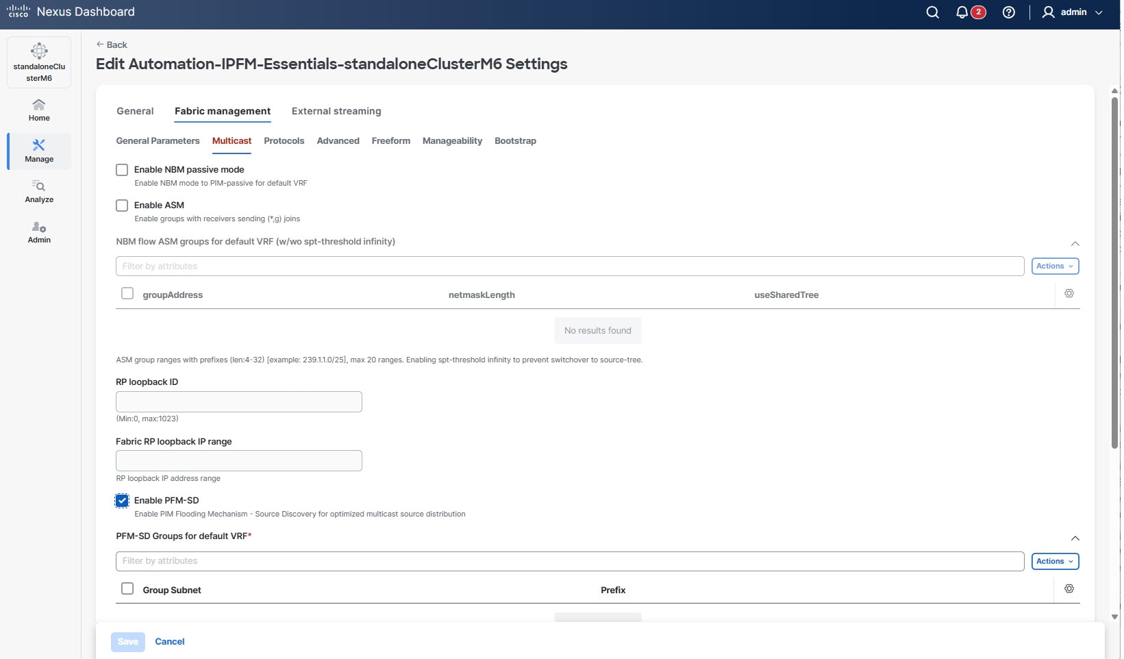
Click the Fabric management tab and then click the Multicast tab.
-
Check the Enable PFM-SD check box.
PFM-SD is enabled for the default VRF across all spine and leaf switches in the fabric.
-
In the PFM-SD Groups for default VRF table, add one or more multicast group ranges eligible for PFM-SD source discovery.
Follow these steps to add multicast group.
-
From the Actions drop-down list, choose Add.
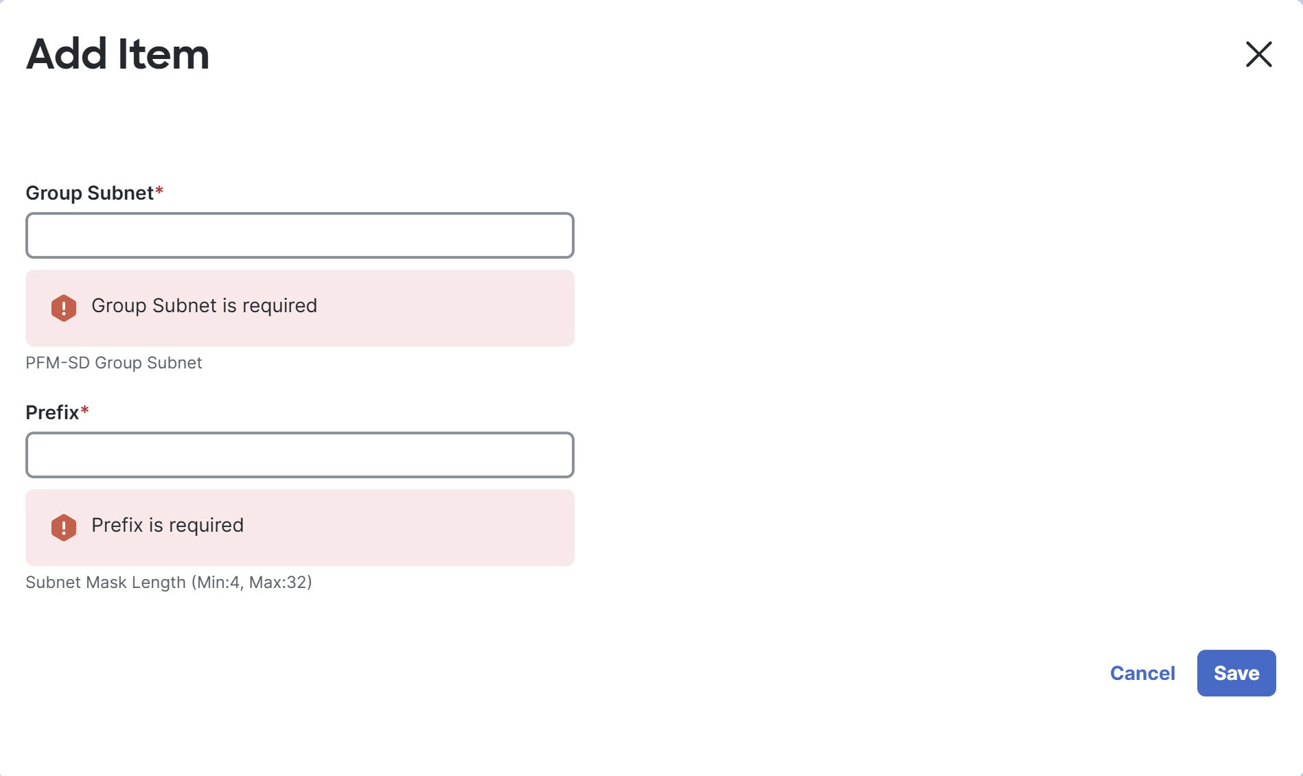
The Add Item dialog box appears.
-
Provide the following values.
-
Group Subnet — provide the IPv4 multicast group subnet address.
-
Prefix — provide the subnet mask length for the multicast group subnet. Valid values range from 4 to 32.
-
-
Click Save to add the group range to the table.
A maximum of 20 group ranges is supported per fabric. At least one group range is required.
-
-
In the PFM-SD Announcement Gap field, provide the minimum time gap (in milliseconds) between consecutive PFM-SD announcements.
This prevents bursts of control-plane traffic and improves scalability when a large number of multicast sources become active simultaneously.
Valid values range from 50 to 65535. The default value is 1000.
-
In the PFM-SD Announcement Rate field, provide the maximum number of PFM-SD announcements sent per interval.
Valid values range from 1 to 65535. The default value is 6.
-
Click Save to save the fabric settings.
-
Go to the Fabric Overview page, choose Actions > Recalculate and deploy to push the configuration to the switches.
-
Review the pending configuration and then click Deploy all.
-
After deployment completes, verify that all switches show an In sync status.
Guidelines and limitations for PFM-SD
-
PFM-SD requires Cisco NX-OS release 10.3(2) or later on all switches in the fabric. If any switch is running an older version, fabric save fails with a version validation error.
-
PFM-SD can be selectively enabled for specific multicast group ranges without impacting existing RP-based groups. Only groups matching the configured ranges use PFM-SD; other groups continue to use RP-based mechanisms if configured.
-
You cannot disable PFM-SD in fabric settings while multi-site policies (
ipfm_pfm_sd_multisite) exist for the default VRF. You must delete the child multi-site policies first and deploy the changes before disabling PFM-SD. -
For non-default VRFs, PFM-SD is configured per-switch using the
ipfm_pfm_sdpolicy template. For more information, see Working with policies when configuring an IPFM fabric. -
For multi-site deployments, each fabric participating in the deployment is configured independently. A deployment may include a mix of PFM-SD-enabled fabrics and traditional RP/MSDP-based fabrics.
Protocols
The fields in this tab are shown below.
| Field | Description |
|---|---|
|
Fabric Routing Protocol Tag |
Specifies the routing process tag for the fabric. |
|
OSPF Area Id |
Specifies the OSPF area ID, if OSPF is used as the IGP within the fabric.
The OSPF or IS-IS authentication fields are enabled based on your selection in the Fabric Routing Protocol field in the General Parameters tab. |
|
Enable OSPF Authentication |
Check the check box to enable OSPF authentication. Clear the check box to disable it. If you enable this field, the OSPF Authentication Key ID and the OSPF Authentication Key fields get enabled. |
|
OSPF Authentication Key ID |
Indicates that the key ID is populated. |
|
OSPF Authentication Key |
Ensure that the OSPF authentication key is the Triple Data Encryption Standard (3DES) key from the switch.
Plain-text passwords are not supported. Log in to the switch, retrieve the encrypted key, and enter it in this field. For more information, see the Retrieving the authentication key section for details. |
|
IS-IS Level |
Choose the IS-IS level. Available options are:
|
|
Enable IS-IS Network Point-to-Point |
Enables network point-to-point on numbered fabric interfaces. |
|
Enable IS-IS Authentication |
Check the check box to enable IS-IS authentication. Clear the check box to disable it. If you enable this field, the IS-IS Key ID field is auto populated. |
|
IS-IS Authentication Keychain Name |
Specifies the name of the IS-IS key chain. |
|
IS-IS Authentication Key ID |
Specifies the IS-IS authentication key ID. |
|
IS-IS Authentication Key |
Specifies the encrypted IS-IS authentication key. Log in to the switch, retrieve the encrypted key, and enter it in this field. A plain-text password gets converted to a Cisco type 7 password. For more information, see the Retrieve the encrypted IS-IS authentication key section for details. |
|
Enable PIM Hello Authentication |
Enables the PIM hello authentication. |
|
PIM Hello Authentication Key |
Specifies the PIM hello authentication key. |
What’s next: Complete the configurations in another tab if necessary, or click Save when you have completed the necessary configurations for this fabric.
Advanced
The fields in this tab are shown below.
| Field | Description |
|---|---|
|
Intra Fabric Interface MTU |
Specifies the maximum transmission unit (MTU) for the intra fabric interface. This value must be an even number. The valid values range from 576 to 9216. This is a mandatory field. |
|
Layer 2 Host Interface MTU |
Specifies the MTU for the Layer 2 host interface. This value must be an even number. The valid values range from 1500 to 9216. |
|
Power Supply Mode |
Choose the appropriate power supply mode that will be the default mode for the fabric from the drop-down list. This is a mandatory field. |
|
Enable CDP for Bootstrapped Switch |
Check this check box to enable the Cisco Discovery Protocol on the management (mgmt0) interface for a bootstrapped switch. By default, for bootstrapped switches, Cisco Discovery Protocol is disabled on the mgmt0 interface. |
|
Enable AAA IP Authorization |
Enables AAA IP authorization, when IP Authorization is enabled in the remote authentication server. This is required to support Nexus Dashboard in scenarios where customers have strict control of which IP addresses can have access to the switches. |
|
Enable NDFC as Trap Host |
Check this check box to enable Nexus Dashboard as an SNMP trap destination. Typically, for a native HA Nexus Dashboard deployment, the eth1 VIP IP address will be configured as SNMP trap destination on the switches. By default, this check box is enabled. |
|
Enable Precision Time Protocol (PTP) |
Enables PTP across a fabric. When you select this check box, PTP is enabled globally and on intra fabric interfaces. Additionally, the PTP Source Loopback Id and PTP Domain Id fields are editable. For more information, see Configuring PTP for IPFM fabrics. |
|
PTP Source Loopback Id |
Specifies the loopback interface ID loopback that is used as the source IP address for all PTP packets. The valid values range from 0 to 1023.
The PTP loopback ID cannot be the same as the RP loopback ID. Otherwise, an error appears. The PTP loopback ID can be the same as the Border Gateway Protocol (BGP) loopback or user-defined loopback that is created from Nexus Dashboard. The PTP loopback will be created automatically if it is not created. |
|
PTP Domain Id |
Specifies the PTP domain ID on a single network. The valid values range from 0 to 127. |
|
PTP Profile |
Select a PTP profile from the list. The PTP profile is enabled only on Inter-Switch Links (ISL) links. The supported PTP profiles are IEEE-1588v2, SMPTE-2059-2, and AES67-2015. |
|
Leaf Freeform Config |
Adds CLIs that should be added to switches that have the Leaf, Border, and Border Gateway roles. |
|
Spine Freeform Config |
Adds CLIs that should be added to switches with a Spine, Border Spine, Border Gateway Spine, and Super Spine roles. |
|
Intra-fabric Links Additional Config |
Adds CLIs that should be added to the intra fabric links. |
What’s next: Complete the configurations in another tab if necessary, or click Save when you have completed the necessary configurations for this fabric.
Freeform
The fields in this tab are shown below. For more information, see "Enable freeform configurations on fabric switches" in Working with Inventory in Your Nexus Dashboard LAN or IPFM Fabrics.
| Field | Description |
|---|---|
|
Leaf Pre-Interfaces Freeform Config |
Enter additional CLIs, added before interface configurations, for all Leafs and Tier2 Leafs as captured from Show Running Configuration. |
|
Spine Pre-Interfaces Freeform Config |
Enter additional CLIs, added before interface configurations, for all Spines as captured from Show Running Configuration. |
|
Leaf Post-Interfaces Freeform Config |
Enter additional CLIs, added after interface configurations, for all Leafs and Tier2 Leafs as captured from Show Running Configuration. |
|
Spine Post-Interfaces Freeform Config |
Enter additional CLIs, added after interface configurations, for all Spines as captured from Show Running Configuration. |
|
Intra-fabric Links Additional Config |
Add CLIs that should be added to the intra-fabric links. |
Manageability
The fields in this tab are shown below.
| Field | Description |
|---|---|
|
DNS Server IPs |
Specifies the comma-separated list of IP addresses (IPv4 or IPv6) of the Domain Name System (DNS) servers. |
|
DNS Server VRFs |
Specifies one VRF for all DNS servers or a comma-separated list of VRFs, one per DNS server. |
|
NTP Server IPs/Hostnames |
Specifies a comma-separated list of IP addresses (IPv4/IPv6) or hostnames for the NTP server. Hostnames are limited to 80 characters in length and must not contain any whitespace or special characters, except for hyphens (-) and periods (.). |
|
NTP Server VRFs |
Specifies one VRF for all NTP servers or a comma-separated list of VRFs, one per NTP server. |
|
Syslog Server IPs/Hostnames |
Specifies a comma-separated list of IP addresses (IPv4/IPv6) or hostnames for the Syslog server. Hostnames are limited to 199 characters in length and should not contain any whitespace or special characters, except for hyphens (-) and periods (.). |
|
Syslog Server Severity |
Specifies a comma-separated list of syslog severity values, one per syslog server. The minimum value is 0 and the maximum value is 7. To specify a higher severity, enter a higher number. |
|
Syslog Server VRFs |
Specifies one VRF for all syslog servers or a comma-separated list of VRFs, one per syslog server. |
|
AAA Freeform Config |
Specifies the AAA freeform Configurations. If AAA configurations are specified in the fabric settings, a switch_freeform Policy Template Instance (PTI) with a source as UNDERLAY_AAA and description as AAAConfigurations is created. |
What’s next: Complete the configurations in another tab if necessary, or click Save when you have completed the necessary configurations for this fabric.
Bootstrap
The fields in this tab are shown below.
| Field | Description |
|---|---|
|
Enable Bootstrap |
Check this check box to enable the bootstrap feature. Bootstrap functionality allows easy day-0 import and bring-up of new devices into an existing fabric. Bootstrap functionality leverages the NX-OS PowerOn Auto Provisioning (POAP) functionality. After you enable bootstrap functionality, you can enable the DHCP server for automatic IP address assignment for POAP using one of the following methods:
|
|
Enable Local DHCP Server |
Check this check box to initiate enabling of automatic IP address assignment through the local DHCP server. When you check this check box, the DHCP Scope Start Address and DHCP Scope End Address fields become editable. If you do not check this check box, Nexus Dashboard uses the remote or external DHCP server for automatic IP address assignment. |
|
DHCP Version |
Select DHCPv4 or DHCPv6 from this drop-down list. When you select DHCPv4, the Switch Mgmt IPv6 Subnet Prefix field is disabled. If you select DHCPv6, the Switch Mgmt IP Subnet Prefix field is disabled.
Cisco N9000 and Cisco Nexus 3000 series switches support IPv6 POAP only when switches are either Layer 2 adjacent (eth1 or out-of-band subnet must be a /64) or they are Layer 3 adjacent residing in some IPv6 /64 subnet. Subnet prefixes except /64 are not supported. |
|
DHCP Scope Start Address |
Specifies the first IP address in the IP address range to be used for the switch out-of-band POAP. |
|
DHCP Scope End Address- |
Specifies the last IP address in the IP address range to be used for the switch out-of-band POAP. |
|
Switch Mgmt Default Gateway |
Specifies the default gateway for the management VRF on the switch. |
|
Switch Mgmt IP Subnet Prefix |
Specifies the prefix for the mgmt0 interface on the switch. The prefix should be between 8 and 30. DHCP scope and management default gateway IP address specification If you specify the management default gateway IP address 10.0.1.1 and subnet mask 24, ensure that the DHCP scope is within the specified subnet, between 10.0.1.2 and 10.0.1.254. |
|
Switch Mgmt IPv6 Subnet Prefix |
Specifies the IPv6 prefix for the mgmt0 interface on the switch. The prefix should be between 64 and 126. This field is editable if you enable IPv6 for DHCP. |
|
Enable AAA Config |
Check this check box to include an AAA configurations from the Manageability tab as part of the device startup configuration post bootstrap. |
|
Bootstrap Freeform Config |
(Optional) Enter additional commands as needed. For example, if you require some additional configurations to be pushed to the device and be available post device bootstrap, they can be captured in this field, to save the desired intent. After the devices boot up, they will contain the configuration defined in the Bootstrap Freeform Config field. Copy-paste the running configuration to a freeform config field with the correct indentation, as seen in the running configuration on the NX-OS switches. The freeform config must match the running configuration. For more information on resolving freeform configuration errors in switches, see the Working with Inventory in Your Nexus Dashboard LAN or IPFM Fabrics. |
|
DHCPv4/DHCPv6 Multi Subnet Scope |
Specifies the field to enter one subnet scope per line. This field is editable after you check the Enable Local DHCP Server check box. The format of the scope should be defined as: |
|
DHCP Scope Start Address, DHCP Scope End Address, Switch Management Default Gateway, Switch Management Subnet Prefix |
For example, 10.6.0.2,10.6.0.9,10.6.0.1,24 |
What’s next: Complete the configurations in another tab if necessary, or click Save when you have completed the necessary configurations for this fabric.
Add switches
A switch can be added to a single fabric at any point in time. To add switches to a fabric and discover existing or new switches, refer to the "Add Switches to a Fabric" section in Working with Inventory in Your Nexus Dashboard LAN or IPFM Fabrics.
Beginning with Nexus Dashboard 4.3.1 release, Nexus Dashboard adds support for the following switches running NX-OS 10.6(3) release:
-
N9348Y12C-SE1
-
N9396Y12C-SE1
-
N9348Y2C6D-SE1U
-
N9396T12C-SE1
-
N9364E-SG2-Q
-
N9364E-SG2-O
Additional settings
The following sections provide information for additional settings that might be necessary when editing the settings for an IPFM fabric.
Retrieving the authentication key
Retrieve the 3DES encrypted OSPF authentication key
-
SSH into the switch.
-
On an unused switch interface, enable the following:
config terminal
    feature ospf
    interface Ethernet1/1
       no switchport
       ip ospf message-digest-key 127 md5 ospfAuth
In the example, ospfAuth is the unencrypted password.
This Step 2 is needed when you want to configure a new key.
-
Enter the show run interface Ethernet1/1 command to retrieve the password.
Switch # show run interface Ethernet1/1
   interface Ethernet1/1
     no switchport
     ip ospf message-digest key 127 md5 3 sd8478f4fsw4f4w34sd8478fsdfw
     no shutdown
The sequence of characters after md5 3 is the encrypted password.
-
Update the encrypted password into the OSPF Authentication Key field.
Retrieve the encrypted IS-IS authentication key
To get the key, you must have access to the switch.
-
SSH into the switch.
-
Create a temporary keychain.
config terminal
   key chain isis
   key 127
   key-string isisAuth
In the example, isisAuth is the plaintext password. This will get converted to a Cisco type 7 password after the CLI is accepted.
-
Enter the show run | section "key chain" command to retrieve the password.
key chain isis
   key 127
       key-string 7 071b245f5a
The sequence of characters after key-string 7 is the encrypted password. Save it.
-
Update the encrypted password into the ISIS Authentication Key field.
-
Remove any unwanted configuration made in Step 2.
Retrieve the 3DES encrypted BGP authentication key
-
SSH into the switch and enable BGP configuration for a non-existent neighbor.
Non-existent neighbor configuration is a temporary BGP neighbor configuration for retrieving the password.
router bgp
   neighbor 10.2.0.2 remote-as 65000
   password bgpAuth
In the example, bgpAuth is the unencrypted password.
-
Enter the show run bgp command to retrieve the password. A sample output:
neighbor 10.2.0.2
   remote-as 65000
   password 3 sd8478fswerdfw3434fsw4f4w34sdsd8478fswerdfw3434fsw4f4w3
The sequence of characters after password 3 is the encrypted password.
-
Update the encrypted password into the BGP Authentication Key field.
-
Remove the BGP neighbor configuration.
Retrieve the encrypted BFD authentication key
-
SSH into the switch.
-
On an unused switch interface, enable the following:
switch# config terminal
switch(config)# int e1/1
switch(config-if)# bfd authentication keyed-SHA1 key-id 100 key passwd
In the example, passwd is the unencrypted password and the key ID is 100.
This Step 2 is needed when you want to configure a new key.
-
Enter the show running-config interface command to retrieve the key.
switch# show running-config interface Ethernet1/1

interface Ethernet1/1
description connected-to- switch-Ethernet1/1
no switchport
mtu 9216
bfd authentication Keyed-SHA1 key-id 100 hex-key 636973636F313233
no ip redirects
ip address 10.4.0.6/30
no ipv6 redirects
ip ospf network point-to-point
ip router ospf 100 area 0.0.0.0
no shutdown
The BFD key ID is 100 and the encrypted key is 636973636F313233.
-
Update the key ID and key in the BFD Authentication Key ID and BFD Authentication Key fields.
Interface configuration for IPFM fabrics
Nexus Dashboard allows you to configure IPFM external links for each switch in your fabric. The external device can connect to the network through this interface by marking it an IPFM external link.
A user with the network operator role in Nexus Dashboard cannot save, deploy, undeploy, or edit interface configurations.
Interfaces in IPFM fabrics are managed by Nexus Dashboard interface manager. The default interface policy for IPFM is int_ipfm_l3_port.
The following issues are seen when an NBM VRF is deleted from Nexus Dashboard after an an interface is enabled with an NBM external link and unicast BW setting. When this occurs, the affected interfaces continue to show the external link and ucast BW as set.
Perform the following steps to resolve interface issues:
-
Choose all the switches that have these interface issues under the Configuration > Policies tab using Add policy.
-
Choose the host_port_resync template and click Save.
-
Select Recalculate & Deploy.
This syncs switch configuration with Nexus Dashboard.
-
Select Resync All.
The following are non-fabric ethernet interface policy templates for IPFM fabrics:
-
int_ipfm_l3_port
-
int_ipfm_access_host
-
int_ipfm_trunk_host
The following are the port-channel interface policy templates for IPFM fabrics:
-
int_ipfm_port_channel_access_host
-
int_ipfm_port_channel_trunk_host
-
int_ipfm_port_channel_access_member
-
int_ipfm_port_channel_trunk_member
The Switch Virtual Interface (SVI) template for IPFM fabrics is int_ipfm_vlan.
Supported templates for configuring interfaces
| Template | Description |
|---|---|
|
GigabitEthernet |
Interface template for creating a GigabitEthernet interface on an IOS XE switch. |
|
GigabitEthernet_freeform |
Interface template for a GigabitEthernet interface using a freeform config on a Cisco Catalyst 9000 series switch. |
|
GigabitEthernet_mgmt |
Interface template for a GigabitEthernet interface using a freeform config on a Cisco Catalyst 9000 series switch. |
|
ios_xe_int_access_host |
Interface template for creating an access switch port on a Cisco Catalyst 9000 series switch. |
|
ios_xe_int_monitor_ethernet |
Interface template for putting an ethernet interface into monitor mode. |
|
ios_xe_int_routed_host |
Interface template for creating a Layer 3 routed port on a Cisco Catalyst 9000 series switch. |
|
ios_xe_int_stackwise_dual_active |
Interface template for a stackwise virtual dual-active detection. |
|
ios_xe_int_stackwise_link |
Interface template for a stackwise virtual link. |
|
ios_xe_int_trunk_host |
Interface template for creating a trunk switchport on a Cisco Catalyst 9000 series switch. |
|
ios_xe_ptp_telemetry_template |
Interface template for configuring PTP monitoring on a Cisco Catalyst 9000 series switch. |
Supported interface types for creating interfaces
You can create the following types of interfaces on a Cisco Catalyst 9000 series switch in a Classic IPFM fabric:
-
Port Channel
-
Virtual Port Channel (VPC)
-
Straight-through (ST) FEX
-
Active-Active (AA) FEX
-
Loopback
-
Tunnel
-
Ethernet
-
Switch Virtual Interface (SVI)
For more information on creating interfaces, see the section "Add interfaces" in Working with Connectivity in Your Nexus Dashboard LAN Fabrics.
Create an interface for IPFM fabrics
This section describes the procedure to create a new interface for an IPFM fabric based on the template that you have selected from the available IPFM fabric interface templates.
IPFM fabrics do not support an IPv6 underlay.
To create an interface for IPFM fabrics, perform these steps:
-
Navigate to the Fabric Overview page for your fabric and click the Connectivity > Interfaces tab.
-
Choose Create new interface from the Actions drop-down list.
The Create new interface page appears.
-
Choose either Port Channel, Loopback, or SVI as the interface type for IPFM.
-
Choose a device from the drop-down list. The switches (spine and leaf) that are a part of the fabric are displayed in the drop-down list.
-
Enter the Port Channel ID, Loopback ID, or VLAN ID, based on your choice of the interface type.
-
Click the No Policy Selected link to select a policy that is specific to IPFM. In the Select Attached Policy Template dialog box, choose the required interface policy template and click Save.
-
Enter the appropriate values in the Policy Options area. Note that the appropriate Policy Options fields are displayed based on the policy.
Field Description Type - Port Channel
Following are the supported types:
-
Port Channel Member Interfaces — Specify a list of member interfaces, for example, e1/5, eth1/7-9.
-
Port Channel Mode — Choose one of the following channel mode options: on, active, or passive.
-
Enable BPDU Guard — Choose one of the following options for a spanning-tree Bridge Protocol Data Unit (BPDU) guard:
-
true — enables bdpuguard
-
false — disables bpduguard
-
no — returns to default settings
-
Enable Port Type Fast
Check this check box to enable spanning-tree edge port behavior.
MTU
Specify the maximum transmission unit (MTU) for the port channel or the MTU for the interface. The valid value range for MTU for the interface is from 576 to 9216.
SPEED
Specify the port channel speed or the interface speed.
Access VLAN
Specify the VLAN for the access port.
Trunk Allowed VLANS
Enter one of the following values:
-
none
-
all
-
VLAN ranges, for example, 1-200, 500-2000, 3000
Enable PTP
Check this check box to enable Precision Time Protocol (PTP) for the host interface for the IPFM fabric. For more information about PTP, see Configuring PTP for IPFM fabrics.
PTP Profile
Choose a PTP profile from the drop-down list: IEEE-1588v2, SMPTE-2059-2, or AES67-2015.
PTP VLAN
Specifies the PTP VLAN for a member interface when PTP is enabled.
Port Channel Description
Enter description for the port channel.
Freeform Config
Enter an additional CLI for the port channel if required.
Enable Port Channel
Check this check box to enable the port channel.
Type - Loopback
Following are the available types:
-
Interface VRF — Enter the name of the interface VRF. Enter default for default VRF.
-
Loopback IP-- Enter an IPv4 address for the loopback interface.
-
Loopback IPv6 address — Enter an IPv6 address for the loopback interface if the VRF is the non-default VRF. For the default VRF, add the IPv6 address in the freeform configuration.
-
Route-Map TAG — Enter the route-map tag associated with the interface IP.
-
Interface Description-- Enter description for the interface. The maximum size limit is 254 characters.
-
Freeform Config — Enter an additional CLI for the loopback interface if required.
-
Enable Interface — Check this check box to enable the interface.
Type - SVI
Following are the available options:
-
Interface VRF-- Enter the name of the interface VRF. Enter default for the default VRF.
-
VLAN Interface IP-- Enter IP address of the VLAN interface.
-
IP Netmask Length — Specify the IP netmask length used with the IP address. The valid value range is from 1 to 31.
-
Routing TAG — Enter the routing tag associated with the interface IP.
-
MTU — Specify the maximum transmission unit (MTU) for the Port Channel or the MTU for the interface. The valid value range for MTU for the interface is from 576 to 9216.
-
Disable IP redirects — Check this check box to disable both IPv4 and IPv6 redirects on the interface.
-
IPFM External-Link-- Check this check box to specify that the interface is connected to an external router.
-
Interface Description-- Enter description for the interface. The maximum size limit is 254 characters.
-
Freeform Config-- Enter an additional CLI for the VLAN interface if required.
-
Enable interface-- Check this check box to enable admin state for the interface.
The Interface Admin State field has been renamed to Enable interface.
-
-
Based on your requirements, click one of the following buttons:
-
Save - Click Save to save the configuration changes.
-
Preview - Click Preview to open the Preview interfaces configuration page and view the details.
-
Deploy - Click Deploy to configure the interfaces.
-
If you want to edit the interface, see Edit an interface for IPFM fabrics.
If your interface is ready, add a policy for configuring the IPFM fabric. For more information, see Add a policy for an IPFM fabric
Create a sub-interface for IPFM fabrics
This section describes the procedure to create a new sub-interface for an IPFM fabric.
-
Navigate to the Fabric Overview page for your fabric and click the Connectivity > Interfaces tab.
-
Select a leaf or a spine switch from the list of devices and choose Actions > Configuration > Create Subinterface.
The Create Subinterface page appears.
-
Click the No Policy Selected link to select a policy that is specific to IPFM.
-
In the Select Attached Policy Template dialog box, choose the int_ipfm_subif policy template and click Select.
-
Enter the appropriate values in the Policy Options area. Note that the appropriate Policy Options fields are displayed based on the policy.
Field Description Type - Port Channel
Following are the supported types:
-
Port Channel Member Interfaces — Specify a list of member interfaces, for example, e1/5, eth1/7-9.
-
Port Channel Mode — Choose one of the following channel mode options: on, active, or passive.
-
Enable BPDU Guard — Choose one of the following options for a spanning-tree Bridge Protocol Data Unit (BPDU) guard:
-
true — enables bdpuguard
-
false — disables bpduguard
-
no — returns to default settings
-
Enable Port Type Fast
Check this check box to enable spanning-tree edge port behavior.
MTU
Specify the maximum transmission unit (MTU) for the port channel or the MTU for the interface. The valid value range for MTU for the interface is from 576 to 9216.
SPEED
Specify the port channel speed or the interface speed.
Access Vlan
Specify the VLAN for the access port.
Trunk Allowed Vlans
Enter one of the following values:
-
none
-
all
-
VLAN ranges, for example, 1-200, 500-2000, 3000
Enable PTP
Check this check box to enable Precision Time Protocol (PTP) for the host interface for the IPFM fabric. For more information about PTP, see Configuring PTP for IPFM fabrics.
PTP Profile
Choose a PTP profile from the drop-down list: IEEE-1588v2, SMPTE-2059-2, or AES67-2015.
PTP VLAN
Specifies the PTP VLAN for a member interface when PTP is enabled.
Port Channel Description
Enter description for the port channel.
Freeform Config
Enter an additional CLI for the port channel if required.
Enable Port Channel
Check this check box to enable the port channel.
Type - Loopback
Following are the available types:
-
Interface VRF — Enter the name of the interface VRF. Enter default for default VRF.
-
Loopback IP-- Enter an IPv4 address for the loopback interface.
-
Loopback IPv6 address — Enter an IPv6 address for the loopback interface if the VRF is the non-default VRF. For the default VRF, add the IPv6 address in the freeform configuration.
-
Route-Map TAG — Enter the route-map tag associated with the interface IP.
-
Interface Description-- Enter description for the interface. The maximum size limit is 254 characters.
-
Freeform Config — Enter an additional CLI for the loopback interface if required.
-
Enable Interface — Check this check box to enable the interface.
Type - SVI
Following are the available options:
-
Interface VRF-- Enter the name of the interface VRF. Enter default for the default VRF.
-
VLAN Interface IP-- Enter IP address of the VLAN interface.
-
IP Netmask Length — Specify the IP netmask length used with the IP address. The valid value range is from 1 to 31.
-
Routing TAG — Enter the routing tag associated with the interface IP.
-
MTU — Specify the maximum transmission unit (MTU) for the Port Channel or the MTU for the interface. The valid value range for MTU for the interface is from 576 to 9216.
-
Disable IP redirects — Check this check box to disable both IPv4 and IPv6 redirects on the interface.
-
IPFM External-Link-- Check this check box to specify that the interface is connected to an external router.
-
Interface Description-- Enter description for the interface. The maximum size limit is 254 characters.
-
Freeform Config-- Enter an additional CLI for the VLAN interface if required.
-
Enable interface-- Check this check box to enable admin state for the interface.
The Interface Admin State field has been renamed to Enable interface.
IPFM Unicast Bandwidth Percentage
Specifies the dedicated percentage of bandwidth for unicast traffic. The remaining percentage is automatically reserved for multicast traffic.
If you leave this field blank, IPFM uses a global unicast bandwidth reservation.
IPFM Bandwidth Capacity Percentage
Specifies the dedicated percentage of bandwidth for this interface.
If you leave this field blank, Nexus Dashboard IPFM uses a global unicast bandwidth reservation.
-
-
Based on your requirements, click one of the following buttons:
-
Save — Click Save to save the configuration changes.
-
Preview — Click Preview to open the Preview interfaces configuration page and view the details.
-
Deploy — Click Deploy to configure the interfaces.
-
If you want to edit the interface, see Edit an interface for IPFM fabrics.
If your interface is ready, add a policy for the IPFM fabric. For more information, see Add a policy for an IPFM fabric.
Edit an interface for IPFM fabrics
This section describes the procedure to edit an existing IPFM fabric interface template. You can either change a template or edit the values for any of the editable parameters in the Policy Options area.
-
Navigate to the Fabrics page.
Go to Manage > Fabrics.
-
From the Fabrics table, click an IPFM fabric.
The Fabric Overview page displays.
-
In the Fabric Overview page, go to Connectivity > Interfaces.
-
Choose an easyFabric_IPFM fabric with an int_ipfm_13_port policy and an Up operational status.
-
From the Actions drop-down list, choose Edit configuration.
The Edit interface(s) page appears.
-
In the Policy field, choose a policy specific to an IPFM fabric.
-
In the Select Attached Policy Template dialog box, choose the required interface policy template and click Save.
-
Edit the required values in the Policy Options area.
Note that the appropriate Policy Options fields are displayed based on the policy. For more information about the parameters, see Create an interface for IPFM fabrics.
The following fields are specific to the int_ipfm_l3_port policy and the subinterface int_ipfm_subif policy:
Field Description IPFM Unicast Bandwidth Percentage
Specifies the dedicated percentage of bandwidth for unicast traffic. The remaining percentage is automatically reserved for multicast traffic.
If you leave this field blank, IPFM uses a global unicast bandwidth reservation.
IPFM Bandwidth Capacity Percentage
Specifies the dedicated percentage of bandwidth for this interface.
If you leave this field blank, Nexus Dashboard IPFM uses a global unicast bandwidth reservation.
IPFM External-Link
Check this check box to specify that the interface is connected to an external router.
Border Router
Check this check box to enable the border router configuration on the interface. The interface is a boundary of a Protocol Independent Multicast (PIM) domain.
Interface Description
Enter a description for the interface. The maximum size limit is 254 characters.
Enable Host Source Group Proxy
Check this check box to enable an IGMP host proxy on the interface. The IGMP host proxy connects a PIM-enabled multicast network to a domain different from the PIM domain.
For more information on configuring an IGMP source group proxy, see the Cisco N9000 Series NX-OX Multicast Routing Configuration Guide.
IGMP Host Source Group Proxy
You can filter by proxy groups, or you can add a new proxy group.
From the Actions drop-down list, choose Add, Edit, Delete, or Insert Above for adding IGMP proxy groups.
When policy groups are associated with an IGMP source group proxy, Nexus Dashboard creates a route map for the corresponding interface. Use the switch-level Deploy option to provision the route map on a switch.
Choose a group from the drop-down list to filter by IGMP proxy groups.
-
Ensure that you check the Enable interface check box.
-
Choose from one of the following options depending on your configuration:
-
Click Save to save the configuration changes.
-
Click Preview to open the Preview interfaces configuration page and view the details.
-
Click Deploy to configure the interfaces.
-
Add a policy for configuring the IPFM fabric. For more information, see Add a policy for an IPFM fabric.
Configure PFM-SD boundary on inter-fabric interfaces
When you enable PFM-SD, first-hop routers announce active multicast sources across the entire fabric. In a multi-site deployment where fabrics are interconnected, these announcements can cross fabric boundaries through inter-fabric interfaces. In some deployments, you may want to contain source discovery within each individual fabric so that each fabric discovers only its own multicast sources.
A PFM-SD boundary blocks PFM-SD advertisements from crossing an inter-fabric interface. Configure a PFM-SD boundary on an interface that connects to a neighbor fabric when you want to keep multicast source discovery contained within the local fabric.
-
The PFM-SD boundary controls whether PFM-SD advertisements cross between fabrics. This is independent of the
ipfm_pfm_sd_multisitepolicy, which uses MSDP to intentionally share source information between fabrics. You can use the boundary when you want to contain source discovery, and use the multi-site policy when you want to share source discovery. For more information, see Add anipfm_pfm_sd_multisitepolicy. -
The PFM-SD boundary option is available on the interface regardless of whether PFM-SD option is enabled at the fabric level. However, the boundary takes effect only when PFM-SD is active in the fabric.
Follow these steps to configure the PFM-SD boundary on an inter-fabric interface.
-
Navigate to the Fabrics page.
Go to Manage > Fabrics.
-
From the Fabrics table, click an IPFM fabric.
The Fabric Overview page displays.
-
In the Fabric Overview page, go to Connectivity > Interfaces.
-
Choose the inter-fabric interface that you want to configure.
-
From the Actions drop-down list, choose Edit configuration.
The Edit Interface(s) page displays.
-
In the Policy Options area, check the IPFM external-link check box.
This marks the interface as connected to a neighbor fabric.
-
Check the PFM-SD Boundary check box.
This applies the
ip pim pfm-sd boundary bothcommand to the interface and blocks PFM-SD advertisements from crossing the fabric boundary. -
Click Save.
-
Click Deploy to push the configuration to the switch.
Configuring PTP for IPFM fabrics
The Precision Time Protocol (PTP) is a protocol used to synchronize clocks throughout a computer network. When creating an interface, if you enable the Enable PTP check box, PTP is enabled across the fabric and on all the intra-fabric interfaces. The supported PTP profiles for IPFM fabrics are IEEE-1588v2, SMPTE-2059-2, and AES67-2015.
A few things to note about the per-interface PTP profile for nonfabric ethernet interfaces are:
-
You must enable PTP and select the PTP profile on each nonfabric ethernet interface.
-
A PTP profile can be different from the fabric-level PTP profile.
-
You must enable PTP in the fabric settings before you can configure PTP on a nonfabric ethernet interface.
If you disable PTP from the fabric settings, Nexus Dashboard removes the PTP configuration from all the interfaces, that is, both the fabric and nonfabric interfaces.
For more information about PTP monitoring for IPFM fabrics, see the section "PTP monitoring" in Working with Inventory in Your Nexus Dashboard LAN or IPFM Fabrics.
With this release, Nexus Dashboard 4.1.1 added support for PTP telemetry monitoring on Cisco Catalyst 9000 series switches. PTP monitoring uses telemetry and the configuration is similar to PTP monitoring for Cisco Catalyst 9000 series switches. You can retrieve statistics from a Cisco Catalyst 9000 series switch using PTP telemetry monitoring.
Nexus Dashboard added a ios_xe_ptp_telemetry policy for configuring PTP telemetry monitoring on Cisco Catalyst 9000 series switches. For more information, see Supported templates for configuring interfaces.
Guidelines for configuring PTP telemetry monitoring on Cisco Catalyst 9000 switches
-
Cisco Catalyst 9000 telemetry configuration requires a user-supplied IP address as the source address for telemetry.
-
The polling interval on a Cisco Catalyst 9000 series switch is 100th of a second, whereas it is a 1000th of a second (millisecond) on a Cisco N9000 series switch. The PTP template uses the same sampling interval for sensors.
-
You can view PTP telemetry sync status on the Switch Overview > PTP page. The Switch Overview > Telemetry Collection or Fabric Overview > Telemetry Status is not applicable for PTP telemetry.
Add the PTP telemetry policy to a Cisco Catalyst 9000 switch
-
Navigate to Manage > Fabrics and click on the fabric for which you want to configure PTP telemetry monitoring.
Fabric Overview displays.
-
Click Configuration Polices.
Configuration Policies > Policies displays.
-
Click Actions > Add policy.
Create Policy displays.
-
Choose the Cisco Catalyst 9000 switch or switches for which you would like to configure PTP monitoring.
-
Click Next.
The Cisco Catalyst 9000 switch or switches appear in Switch List.
-
In the Description field, enter telemetry.
The Select Policy Template dialog box displays.
-
In the search field, enter telemetry.
The ios_xe_ptp_telemetry policy displays.
-
Click Select.
-
If you are configuring a single Cisco Catalyst 9000 switch, enter the switch management IP address in the Telemetry Source IP Address field. If you are configuring multiple Cisco Catalyst 9000 switches, leave the Telemetry Source IP Address field empty.
-
In the Telemetry VRF field, specify Mgmt-vrf as the source VRF.
-
In the Telemetry Receiver IP Address field, use the same IP address as you used for importing the Cisco Catalyst 9000 series switch in Nexus Dashboard.
-
In the PTP Monitoring Interval field, specify a period in units of 100ths of a second.
-
Click Save.
-
Navigate to Manage > Fabrics > Configuration Policies > Policies.
-
Click Actions > Recalculate and deploy in the toolbar to push the configuration to the Cisco Catalyst 9000 switch or switches.
Deploy Configuration displays the progress of the deploy operation and the pending configurations.
-
On Deploy Configuration, if you click the hyperlink in Pending Config, you can view the pending configuration, which configures the PTP telemetry template.
-
Click Deploy All to deploy the pending configurations.
-
Once the deployment is successful, click Close.
Verify the PTP telemetry policy configuration
-
Navigate to Manage > Inventory > Switches to verify that the Cisco Catalyst 9000 switch or switches you added are included in the list of switches.
-
Click on a Cisco Catalyst 9000 switch on which you configured PTP monitoring.
Switch Overview displays.
-
Click PTP for viewing the port status, corrections, and clock status for the telemetry policy pushed to the switch. For more information, see the "PTP monitoring" section in Working with Inventory in Your Nexus Dashboard LAN or IPFM Fabrics.
Edit a PTP telemetry policy configuration
-
Navigate to Manage > Fabrics and click on the IPFM fabric for which you want to edit your PTP configuration.
The Fabric Overview page displays.
-
Click Configuration Polices.
-
Choose the PTP telemetry policy you want to edit and click Edit policy from the Actions drop-down list.
The Edit policy page appears.
-
Edit the necessary fields.
-
Click Save to save your edits.
-
Click Recalculate and deploy.
View the PTP telemetry policy configuration on Topology
-
Navigate to Manage > Fabrics and click on the IPFM fabric for which you want to view your PTP configuration.
The Fabric Overview page displays.
-
Click View in topology to view a visual representation of the Cisco Catalyst 9000 switch or switches you added for PTP monitoring.
Creating an IPFM fabric group
A Society of Motion Picture and Television Engineers (SMPTE 2022-7)-enabled transmitter duplicates an input stream and sends the input stream using two different paths to a destination receiver, which is also SMPTE 2022-7 enabled. The receiver combines the streams from both paths and reconstructs the original stream. If a packet is lost on path 1, the packet is taken from path 2. This involves two active IPFM fabrics named as red and blue fabrics. You can choose to name the IPFM fabrics other than red and blue fabrics.
You can group 2022-7 redundant fabrics into a fabric group. This feature allows you to associate endpoints and multicast groups from both fabrics for a side-by-side topology view for individual flows.
There is no change to the topology view compared to prior releases if there is no associated redundant flow or the IPFM fabrics are not grouped.
Benefits of creating an IPFM fabric group
-
Provides high availability with two switches in an IPFM fabric group
-
Provides a single entity for managing IPFM fabrics
-
Supports a side-by-side view of the red and blue fabrics for managing and monitoring both fabrics
-
Supports the SMPTE 2022-7 standard for sending digital video over an IP network
-
Provides endpoint group and multicast group associations
Guidelines and limitations for creating an IPFM fabric group
-
You cannot have more than two IPFM fabrics in a single fabric group. If you try to add a third IPFM fabric to a fabric group, you receive an error message.
Create an IPFM fabric group
An IPFM fabric group can contain individual IPFM, IPFM Classic, or Classic LAN fabrics. An IPFM fabric group allows for shared host and flow definitions.
For information on how to create an IPFM fabric group, see the section "Create fabric groups" in Creating Fabrics and Fabric Groups.
Add a child IPFM fabric to an IPFM fabric group
For information on how to add a child IPFM fabric to an IPFM fabric group, see the section "Add child fabrics to the fabric group" in Creating Fabrics and Fabric Groups.
Associate hosts from two fabrics in a host group
By adding two hosts to the host group, the hosts are associated together and are linked, so you can view the hosts in a side-by-side visual representation.
To associate hosts to a host group, perform the following steps:
-
Click Manage > Fabrics > Fabric Groups.
-
Choose a fabric group.
The Overview page of the fabric group displays.
-
Click Connectivity > Host Groups.
-
Click Actions > Add Host Group.
The Add Host Group page displays.
To link hosts from two IPFM fabrics, you need to specify the VRF associated with the fabric where the host resides, as well as enter the IP address of the host for each fabric. Optionally, you can add an alias to each host for better recognition.
Field
Description
VRF
Specify the VRF associated with the fabric for where each host resides.
IP Address
Enter the host IP address of the red fabric.
Host Alias
(Optional) Enter the host alias for the red fabric.
IP Address
Enter the host IP address of the blue fabric.
Host Alias
(Optional) Enter the host alias for the ble fabric.
-
Click Save.
Nexus Dashboard adds the hosts to the host group view where you can view the hosts in a side-by-side visual representation.
Associate flows to a host group
To associate flows to a host group, perform the following steps:
-
Click Manage > Fabrics > Fabric Groups.
-
Choose a fabric group.
The Overview page of the fabric group displays.
-
Click Connectivity > Flow Groups.
-
On the Flow Groups page, click Actions > Add Flow Group.
To link flows from two IPFM fabrics in a flow group, you need to specify the VRF associated with the fabric where the flow resides, as well as enter the multicast destination IP address of the flows in each fabric. Optionally, you can add a flow alias and a description for better recognition. Nexus Dashboard adds the flows to the host group view in a side-by-side representation.
Field
Description
VRF
Specify the VRF associated with the fabric for where the flow resides.
IP Address
Enter the multicast IP address for the red fabric.
Flow Alias
(Optional) Enter the flow alias for the red fabric.
Description
(Optional) Enter the description for the red fabric.
IP Address
Enter the multicast IP address for the blue fabric.
Flow Alias
(Optional) Enter the flow alias for the ble fabric.
Description
(Optional) Enter the description for the blue fabric.
-
Click Save and close the Fabric Overview page.
Nexus Dashboard adds the flows to the flow group view where you can view a side-by-side representation of both flows.
View side-by-side associations of IPFM member fabrics
You can view side-by-side associations of IPFM member fabrics on the Flows > Flow Status page.
-
Navigate to the Manage > Fabrics page, and click on a child member of an IPFM fabric group.
The Fabric Overview page displays.
-
Click on Connectivity > Flows.
-
Click on Flow Status and under the Flow Link State column, click on the active link.
Nexus Dashboard displays a side-by-side representation of the two fabrics and the grouped flows.
-
To access the same page from the topology view, click View in topology.
-
Right-click on the fabric group and click Detailed View.
The Fabric Overview page displays.
-
Right-click on a member of the fabric group.
The Fabric Overview page displays.
Working with policies when configuring an IPFM fabric
Fabric settings apply a uniform configuration across all leaf and spine switches in a fabric. When you need to configure a feature on specific switches, or configure settings that differ between switches, you can use policy templates.
Nexus Dashboard provides several policy templates for IPFM fabrics. The following are the available templates.
|
Policy template |
Purpose |
|
|
Configures NAT TCAM on Cisco Catalyst 9300 switches. |
|
|
Configures telemetry for IPFM fabrics. |
|
|
Configures VRF settings, including routing, PIM, and ASM. |
|
|
Configures PFM-SD for a non-default VRF on a specific switch. |
|
|
Configures MSDP peering between border switches in neighbor fabrics for inter-fabric multicast source sharing. |
Add a policy for an IPFM fabric
Follow these steps to add a policy to one or more switches in an IPFM fabric.
-
Navigate to the Fabrics page.
Go to Manage > Fabrics.
-
From the Fabrics table, click an IPFM fabric.
The Fabric Overview page displays.
-
Click the Configuration policies tab.
-
From the Actions drop-down list, choose Add policy.
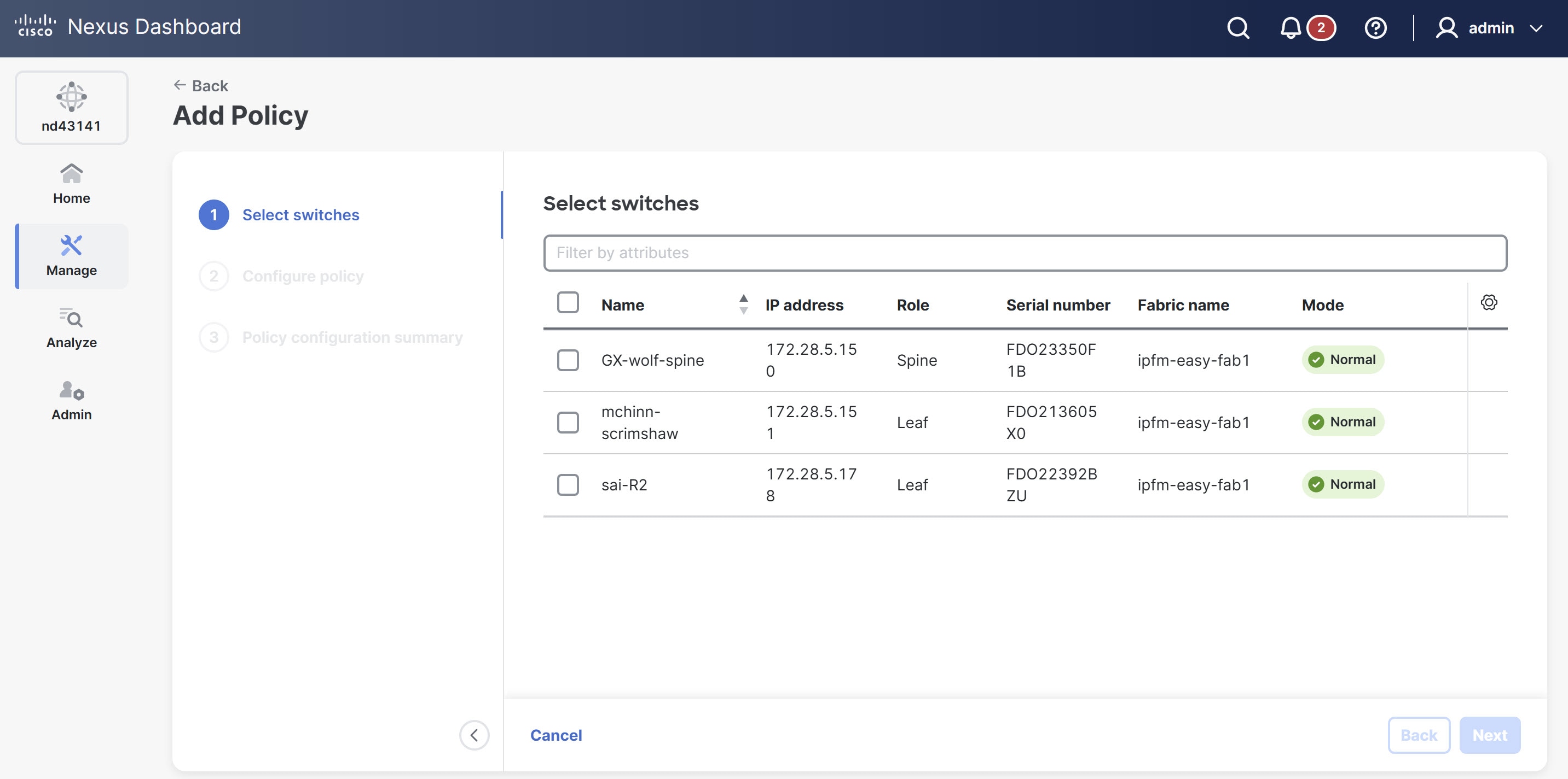
The Add Policy page displays.
-
Choose one or more switches and click Next.
-
Under Configure policy, click Select Policy Template.
The Select Policy Template page appears.
-
Choose the required template, for example, ipfm_tcam_nat_9300.
-
Click Select.
-
Enter a priority for the template. The valid value ranges are from 1 to 1000.
-
Enter the values in the template-specific fields, then click Save.
The fields that appear depend on the template you chose. For example, the ipfm_tcam_nat_9300 template requires you to enter the TCAM size in increments of 256.
-
Navigate to Manage > Fabrics > Configuration Policies > Policies.
-
From the toolbar, choose Actions > Recalculate and deploy to push the configuration to the switch or switches.
-
Review the pending configuration and then click Deploy all.
-
After deployment, verify that all switches show an In sync status.
Edit a policy for an IPFM fabric
Follow these steps to edit an existing policy on a switch in an IPFM fabric.
-
Navigate to the Fabrics page.
Go to Manage > Fabrics.
-
From the Fabrics table, click an IPFM fabric.
The Fabric Overview page displays.
-
Click the Configuration policies tab.
-
From the policies table choose the policy you want to edit.
-
From the Actions drop-down list, choose Edit policy.
The Edit policy page appears.
-
Make the required changes and click Save & view summary.
-
From the toolbar, choose Actions > Recalculate and deploy to push the updated configuration to the switches.
-
Review the pending configuration and then click Deploy all.
-
After deployment, verify that all switches show an In sync status.
PFM-SD policies for non-default VRFs and multi-site deployments
Nexus Dashboard provides the following two additional policy templates to support PFM-SD in non-default VRFs and across multi-site deployments.
| Template | Purpose |
|---|---|
|
ipfm_pfm_sd |
Configures PFM-SD for a non-default VRF on a specific switch. |
|
ipfm_pfm_sd_multisite |
Configures MSDP peering between border switches in neighbor fabrics for inter-fabric multicast source sharing. |
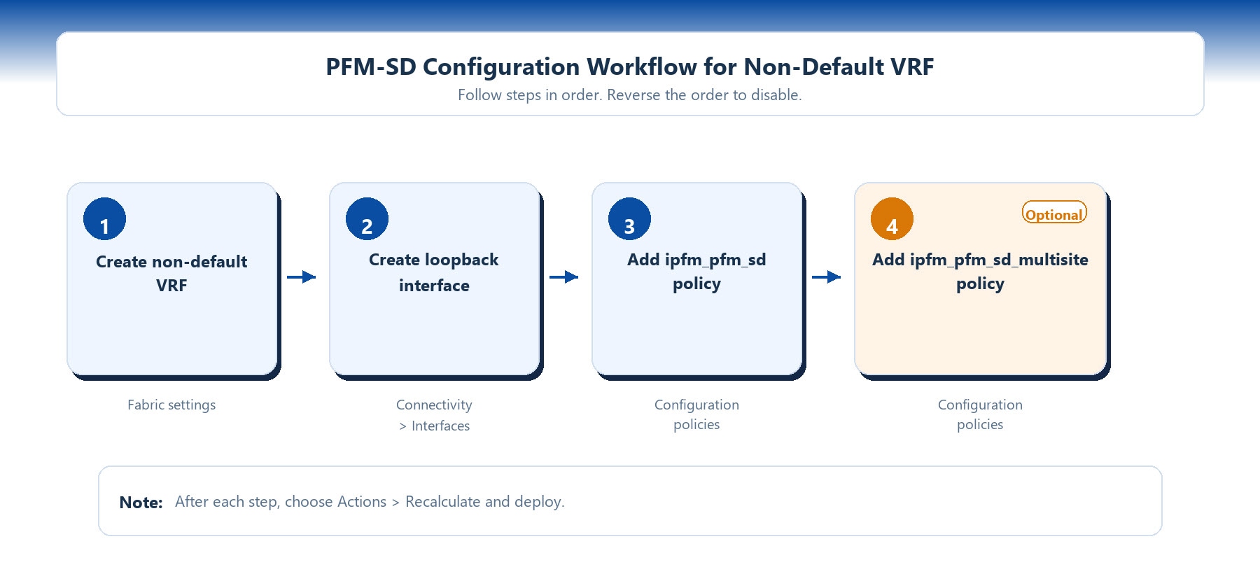
The ipfm_pfm_sd_multisite policy depends on the ipfm_pfm_sd policy. Before you create an ipfm_pfm_sd_multisite policy, an ipfm_pfm_sd policy must already exist for the same VRF on the same switch. You also cannot delete an ipfm_pfm_sd policy while an ipfm_pfm_sd_multisite policy exists for the same VRF. You must first delete the ipfm_pfm_sd_multisite policy.
The following diagram illustrates the configuration workflow for PFM-SD on a non-default VRF.
Prerequisites for configuring PFM-SD on a non-default VRF
Before you can add an ipfm_pfm_sd policy for a non-default VRF, you must complete the following prerequisite tasks in order.
-
Create the non-default VRF on the fabric.
-
Create a loopback interface and assign it to the non-default VRF.
These prerequisites are required because the ipfm_pfm_sd policy uses the loopback interface in the non-default VRF as the source IP for PFM-SD announcements. If either is missing, the policy deployment fails with a validation error.
These prerequisites apply only to non-default VRF configurations. For the default VRF, PFM-SD is configured directly through fabric settings and does not require these steps.
Create a non-default VRF
Follow these steps to create a non-default VRF on an IPFM fabric.
-
Navigate to the Fabrics page.
Go to Manage > Fabrics.
-
From the Fabrics table, click an IPFM fabric.
The Fabric Overview page displays.
-
Click the Configuration policies tab.
-
From the Actions drop-down list, choose Add policy.
The Add Policy page displays.
-
Under Select switches, choose the switches for which you want to create non-default VRF and click Next.
-
Under Configure policy, provide the following information.
Field Description Switch list
Displays the switches you chose.
Priority
Provide a priority value for this policy. Valid values range from 1 to 1000. The default value is 500.
Description
Provide a description for the VRF.
Policy template
-
Click Select policy template.
-
In the Filter by attributes field, choose Name, contains, and enter
ipfm_vrf. -
From the policies table choose
ipfm_vrfand click Select.
Group
Click the toggle button to create a single policy instance shared across all chosen switches, instead of creating individual policy instances per switch. You can use this option when you want to apply the same VRF configuration uniformly to multiple switches.
-
-
In the VRF name field, provide a unique name for the non-default VRF (for example,
red). -
Click Save to save the configuration.
The new configuration appears under the Policy configuration summary.
-
Click Done.
-
Navigate to the Fabric Overview page, from the Actions drop-down list, choose Recalculate and deploy to push the VRF configuration to the switches.
-
Review the pending configuration, then click Deploy all.
-
After deployment completes, verify that all switches show an In sync status.
Create a loopback interface for the non-default VRF
After the non-default VRF is created and deployed, create a loopback interface and assign it to that VRF. This loopback serves as the source interface for PFM-SD announcements.
Follow these steps to create a loopback interface for the non-default VRF.
-
Navigate to the Fabrics page.
Go to Manage > Fabrics.
-
From the Fabrics table, click an IPFM fabric.
The Fabric Overview page displays.
-
Click the Inventory tab.
-
From the Switches table, click the switch on which you want to create the loopback interface.
The Switch Overview page displays.
-
In the Switch Overview page, click the Connectivity tab.
-
In the Interfaces table, click Actions > Create interface.
The Create interface page displays.
-
From the Type drop-down list, choose Loopback.
-
From the Select a device drop-down list, choose the switch on which you want to create the loopback interface.
-
In the Loopback ID field, provide a unique loopback ID.
-
In the Policy options area, provide the following information.
Field Description Interface VRF
Provide the name of the non-default VRF you created earlier (for example,
red).For more information, see Create a non-default VRF.
Loopback IP
Provide an IPv4 address for the loopback interface. You must assign this IP address manually.
Secondary loopback ips
(Optional)
Routing tag
(Optional) Provide the routing tag associated with the interface IP.
Advertise loopback
(Optional)Check this option to advertise loopback by configuring OSPF/IS-IS on the interface.
Is service-reflect interface
(Optional)Check this option if this loopback used as service reflect source. Change of this parameter requires recalculate config from the fabric.
Interface description
(Optional) Provide a description for the interface. The maximum size limit is 254 characters.
Freeform Config
(Optional) Provide additional CLI commands for the loopback interface if required.
Enable Interface
Check this check box to enable the interface.
OSPF and PIM parameters are automatically added by the template. You only need to manually assign the loopback IP address and the VRF.
-
Click Save.
-
Navigate to the Fabrics page (go to Manage > Fabrics).
-
From the Actions drop-down list, choose Recalculate and deploy to push the loopback configuration to the switch.
-
Review the pending configuration, then click Deploy all
After you create a non-default VRF and a loopback interface you can enable PFM-SD for the switch. For more information. see Enable PFM-SD.
Add an ipfm_pfm_sd policy (non-default VRF)
You can use the ipfm_pfm_sd policy to configure PFM-SD for a non-default VRF on a specific switch. The default VRF is configured at the fabric level through fabric settings and does not require this policy.
Follow these steps to add an ipfm_pfm_sd policy.
-
Navigate to the Fabrics page.
Go to Manage > Fabrics.
-
From the Fabrics table, click an IPFM fabric.
The Fabric Overview page displays.
-
Click the Inventory tab.
-
From the Switches table, click the switch.
The Switch Overview page displays.
-
In the Switch Overview page, click the Configuration policies tab.
-
From the Actions drop-down list, choose Add policy.
The Add Policy page displays.
-
Under Configure policy, provide description of the PFM-SD policy.
-
Click Select Policy Template.
The Select Policy Template page appears.
-
In the Select Policy Template page, in the Filter by attributes field, choose Name, contains, and enter
pfm_sd. -
From the policies table choose
ipfm_pfm_sdand click Select.The following fields display under Configure policy.
Field Description VRF Name
Provide the non-default VRF name.
Originator Loopback
Provide the loopback interface ID used as the PFM-SD source. The loopback must exist in the specified VRF. Valid values range from 0 to 1023.
PFM-SD Announcement Gap
Provide the gap in milliseconds between announcements. Valid values range from 100 to 65535. The default value is 1000.
PFM-SD Announcement Rate
Provide the rate of announcements per interval. Valid values range from 1 to 60. The default value is 10.
-
In the PFM-SD Groups table, add one or more multicast group ranges eligible for PFM-SD source discovery.
Follow these steps to add multicast group.
-
From the Actions drop-down list, choose Add.
The Add Item dialog box appears.
-
Provide the following values.
-
Group Subnet — provide the IPv4 multicast group subnet address.
-
Prefix — provide the subnet mask length for the multicast group subnet. Valid values range from 4 to 32.
-
-
Click Save to add the group range to the table.
-
-
Click Save.
You can view the summary of policy changes under Policy configuration summary.
-
Navigate to Manage > Fabrics.
-
From the Actions drop-down list, choose Recalculate and deploy to push the configuration to the switch.
-
Review the pending configuration, then click Deploy all.
Add an ipfm_pfm_sd_multisite policy
You can use the ipfm_pfm_sd_multisite policy to configure MSDP peering on a border switch for inter-fabric multicast source sharing.
Ensure that an ipfm_pfm_sd policy already exists for the target VRF on this switch. For the default VRF, ensure that PFM-SD is enabled in fabric settings. The switch must be running Cisco NX-OS Release 10.6(3) or later.
Follow these steps to add an ipfm_pfm_sd_multisite policy.
-
Navigate to the Fabrics page.
Go to Manage > Fabrics.
-
From the Fabrics table, click an IPFM fabric.
The Fabric Overview page displays.
-
Click the Inventory tab.
-
From the Switches table, click the switch.
The Switch Overview page displays.
-
In the Switch Overview page, click the Configuration policies tab.
-
From the Actions drop-down list, choose Add policy.
The Add Policy page displays.
-
Under Select switches, choose the switch on which you want to configure the PFM-SD policy and click Next.
-
Under Configure policy, provide description of the PFM-SD policy.
-
Click Select Policy Template.
The Select Policy Template page appears.
-
In the Select Policy Template page, in the Filter by attributes field, choose Name, contains, and enter
pfm_sd. -
From the policies table choose
ipfm_pfm_sd_multisiteand click Select.The following fields display under Configure policy.
Field Description VRF Name
Provide the VRF name. The VRF name must match the VRF used in
ipfm_pfm_sd policy(or use default for fabric-level PFM-SD).MSDP Peer IPs
Specifies the list of MSDP peer IP addresses from the neighbor fabrics. Use the Actions drop-down list to add, edit, or delete peer IPs. At least one peer IP is required.
You must create
ipfm_pfm_sdpolicy for the same VRF on this switch before adding MSDP peer IPs.
Use Custom Multisite Route-Map
Check this check box to define a custom route-map for multi-site SA (Source Active) message filtering that is separate from the local PFM-SD route-map.
Checking this check box enables the Multisite PFM-SD Groups table. You must configure at least one multi-site group range.
-
In the Multisite PFM-SD Groups table, add one or more multicast group ranges eligible for PFM-SD source discovery.
Follow these steps to add multicast group.
-
From the Actions drop-down list, choose Add.
The Add Item dialog box appears.
-
Provide the following values.
-
Group Subnet — provide the IPv4 multicast group subnet address.
-
Prefix — provide the subnet mask length for the multicast group subnet. Valid values range from 4 to 32.
-
-
Click Save to add the group range to the table.
-
-
Click Save.
You can view the summary of policy changes under Policy configuration summary.
-
Navigate to Manage > Fabrics.
-
From the Actions drop-down list, choose Recalculate and deploy to push the configuration to the switch.
-
Review the pending configuration, then click Deploy all.
Disable PFM-SD
Disabling PFM-SD removes the PFM-SD configuration from all switches in the fabric. To disable PFM-SD on a fabric without encountering validation errors, you must delete its dependent policies in the correct reverse order of creation.
-
Deleting a policy removes the entire policy from the switch, not just individual peer addresses or group ranges.
-
Non-default VRF PFM-SD configurations do not appear in the default fabric settings. They must be deleted as separate per-switch policies before the fabric-level PFM-SD can be disabled.
-
If you attempt to disable PFM-SD while child policies still exist, Nexus Dashboard displays a validation error preventing the save operation.
Follow these steps to disable PFM-SD on an IPFM fabric.
-
Delete all
ipfm_pfm_sd_multisitepolicies. Navigate to Configuration policies and choose each multi-site policy. Click Actions > Delete policy. Then choose Actions > Recalculate and deploy to remove the MSDP configuration from the switches. -
Delete all
ipfm_pfm_sdpolicies for non-default VRFs. Navigate to Configuration policies and choose eachipfm_pfm_sdpolicy. Click Actions > Delete policy. Then choose Actions > Recalculate and deploy to remove the non-default VRF PFM-SD configuration. -
Disable PFM-SD in fabric settings. From the Fabric Overview page, choose Actions > Edit fabric settings. Click the Fabric management tab, then click the Multicast tab. Uncheck the Enable PFM-SD check box and click Save.
-
In the Fabric Overview page, choose Actions > Recalculate and deploy to remove the default VRF configuration.
-
Review the pending configuration, then click Deploy all.
-
After deployment completes, verify that all switches show an In sync status.
Copyright
THE SPECIFICATIONS AND INFORMATION REGARDING THE PRODUCTS IN THIS MANUAL ARE SUBJECT TO CHANGE WITHOUT NOTICE. ALL STATEMENTS, INFORMATION, AND RECOMMENDATIONS IN THIS MANUAL ARE BELIEVED TO BE ACCURATE BUT ARE PRESENTED WITHOUT WARRANTY OF ANY KIND, EXPRESS OR IMPLIED. USERS MUST TAKE FULL RESPONSIBILITY FOR THEIR APPLICATION OF ANY PRODUCTS.
THE SOFTWARE LICENSE AND LIMITED WARRANTY FOR THE ACCOMPANYING PRODUCT ARE SET FORTH IN THE INFORMATION PACKET THAT SHIPPED WITH THE PRODUCT AND ARE INCORPORATED HEREIN BY THIS REFERENCE. IF YOU ARE UNABLE TO LOCATE THE SOFTWARE LICENSE OR LIMITED WARRANTY, CONTACT YOUR CISCO REPRESENTATIVE FOR A COPY.
The Cisco implementation of TCP header compression is an adaptation of a program developed by the University of California, Berkeley (UCB) as part of UCB’s public domain version of the UNIX operating system. All rights reserved. Copyright © 1981, Regents of the University of California.
NOTWITHSTANDING ANY OTHER WARRANTY HEREIN, ALL DOCUMENT FILES AND SOFTWARE OF THESE SUPPLIERS ARE PROVIDED “AS IS" WITH ALL FAULTS. CISCO AND THE ABOVE-NAMED SUPPLIERS DISCLAIM ALL WARRANTIES, EXPRESSED OR IMPLIED, INCLUDING, WITHOUT LIMITATION, THOSE OF MERCHANTABILITY, FITNESS FOR A PARTICULAR PURPOSE AND NONINFRINGEMENT OR ARISING FROM A COURSE OF DEALING, USAGE, OR TRADE PRACTICE.
IN NO EVENT SHALL CISCO OR ITS SUPPLIERS BE LIABLE FOR ANY INDIRECT, SPECIAL, CONSEQUENTIAL, OR INCIDENTAL DAMAGES, INCLUDING, WITHOUT LIMITATION, LOST PROFITS OR LOSS OR DAMAGE TO DATA ARISING OUT OF THE USE OR INABILITY TO USE THIS MANUAL, EVEN IF CISCO OR ITS SUPPLIERS HAVE BEEN ADVISED OF THE POSSIBILITY OF SUCH DAMAGES.
Any Internet Protocol (IP) addresses and phone numbers used in this document are not intended to be actual addresses and phone numbers. Any examples, command display output, network topology diagrams, and other figures included in the document are shown for illustrative purposes only. Any use of actual IP addresses or phone numbers in illustrative content is unintentional and coincidental.
The documentation set for this product strives to use bias-free language. For the purposes of this documentation set, bias-free is defined as language that does not imply discrimination based on age, disability, gender, racial identity, ethnic identity, sexual orientation, socioeconomic status, and intersectionality. Exceptions may be present in the documentation due to language that is hardcoded in the user interfaces of the product software, language used based on RFP documentation, or language that is used by a referenced third-party product.
Cisco and the Cisco logo are trademarks or registered trademarks of Cisco and/or its affiliates in the U.S. and other countries. To view a list of Cisco trademarks, go to this URL: https://www.cisco.com/go/trademarks. Third-party trademarks mentioned are the property of their respective owners. The use of the word partner does not imply a partnership relationship between Cisco and any other company. (1110R)
© 2017-2026 Cisco Systems, Inc. All rights reserved.
Americas Headquarters
Cisco Systems, Inc.
170 West Tasman Drive
San Jose, CA 95134-1706
USA
https://www.cisco.com
Tel: 408 526-4000
800 553-NETS (6387)
Fax: 408 527-0883