
Cisco Nexus Hyperfabric — Install a Cisco EBox storage cluster
Cisco Nexus Hyperfabric and Cisco EBox storage clusters
This document provides information about installing a Cisco EBox storage cluster using Cisco UCSC-C225-M8N rack servers, which you can manage using Cisco Nexus Hyperfabric.
 Note
Note"EBox storage cluster" is the Cisco name for a VAST Data storage cluster.
Cisco EBox storage cluster site survey
Before you install a Cisco EBox storage cluster, prepare this information:
- Collect the list of serial numbers of all EBoxes.
- Collect the numerical order in which the EBoxes are mounted in racks from top to bottom along with the rack number.
- Prepare and reserve the IP pool ranges as per the Required services and IP pool ranges table.
|
Service or IP pool type |
Description |
Quantity |
Cluster local |
|---|---|---|---|
|
DNS IP addresses |
Collect the list of IP addresses that are assigned for the DNS service to be used by the cluster. |
At least 1. |
No |
|
NTP service IP addresses |
Collect the list of IP addresses that are assigned for the NTP service to be used by the cluster. |
At least 1. |
No |
|
Storage-Internal |
This IP pool is used for inter-storage server communication. |
Three /18 subnets. |
Yes |
|
Storage-Mgmt |
This IP pool is used for managing the x86 host and CIMC of the EBoxes. |
2 per EBox, 1 for the x86 host and 1 for CIMC. For example, if you have 12 EBoxes, you need 24 IP addresses. 1 per cluster for hosting the storage management service |
Yes |
|
Storage-External |
This IP pool is used for client-to-storage server communication. |
8 per EBox. For example, if you have 12 EBoxes, you need 96 IP addresses. |
No |
Guidelines for using a support host
You must use a support host to install and configure a Cisco EBox storage cluster if you use the 172.16.0.0/16 subnet for internal communications (the Storage-Internal logical network) and the subnet is routable. A support host is also known as a jump host.
These guidelines apply if you use a support host:
- If your support host has an IP address of 10.10.100.10/24 and the management IP address of your first cluster node is 10.10.100.100/24, then you must set the default route on the cluster node to point to 10.10.100.10.
- The support host should be on the same subnet as the management interface of the cluster nodes.
Example logical networks for a Cisco EBox storage cluster
This table provides example information about the logical networks that you must configure for Cisco Nexus Hyperfabric before you can install a Cisco EBox storage cluster.
|
Logical network |
VRF instance |
Leaf switch port |
VLAN |
Anycast gateway (SVI) IP address |
Quality of Service configuration |
Subnet |
|---|---|---|---|---|---|---|
|
Storage-Broadcast |
VrfStorageInt |
HF6100-32D Storage_Leaf1, Storage_Leaf2: Ethernet1_1 to Ethernet1_24 |
10 - untagged |
— |
— |
— |
|
Storage-Internal |
VrfStorageInt |
HF6100-32D Storage_Leaf1, Storage_Leaf2: Ethernet1_1 to Ethernet1_12 |
69 - tagged |
172.16.128.254 /24 |
RDMA DSCP: 26, PFC and ECN enabled (queue 3 because PFC is required) |
172.16.128.0 /24 |
|
CNP DSCP: 48, PFC is not required (queue 6 because strict priority is enabled on queue 61) |
||||||
|
Storage-External |
VrfFrontEnd |
HF6100-32D Storage_Leaf1, Storage_Leaf2: Ethernet1_13 to Ethernet1_24 HF6100-64ED FrontEnd_Leaf1, FrontEnd_Leaf2: FrontEnd_Ports2 |
200 - tagged |
10.198.54.129 /253 |
RDMA DSCP: 26, PFC and ECN enabled (queue 3 because PFC is required) |
10.198.54.128 /25 |
|
CNP DSCP: 48, PFC is not required (queue 6 because strict priority is enabled on queue 61) |
||||||
|
Mgmt-External (Mgmt-OOB)4 |
VrfMgmtNet |
HF6100-60L4D BMC_Leaf: 245 ports connected to C225-M8 CIMC/BMC Mgmt 1G and x86 Mgmt mLOM port 0 10G |
Untagged |
10.10.10.1/24 |
— |
10.10.10.0/24 |
|
Mgmt-Internal (CIMC/BMC)4 |
VrfMgmtNet |
HF6100-60L4D BMC_Leaf: 245 ports connected to C225-M8 BF3 BMC 1G |
Untagged |
10.10.2.1/24 |
— |
— |
1 We recommend that you assign only CNP traffic to queue 6.
2 For the Storage-External logical network, the FrontEnd_Leaf1 and FrontEnd_Leaf2 ports connect to the GPU server's frontend ports. See External connectivity to the storage switches.
3 This part of the network has 8 IP addresses per server and the IP addresses must be routable if the storage servers need to be accessible outside of the subnet. We recommend that you use the SVI IP address owned by Nexus Hyperfabric as the default gateway for servers.
4 The Mgmt-External and Mgmt-Internal logical networks are not explicitly discussed in this document. These networks do not need to be connected to Nexus Hyperfabric.
5 You need 2 ports per server. With an example of 12 servers, you need 24 ports.
This additional information applies to the table:
- The table assumes 12 servers as an example. You must use different leaf switch port ranges depending on the number of servers for your configuration. For example, if you have 11 servers, the Storage-Internal ports would be Ethernet1_1 to Ethernet1_11, the Storage-Broadcast ports would be Ethernet1_1 to Ethernet1_22, and the Storage-External ports would be Ethernet1_12 to Ethernet1_22.
- The table includes different VRF instances for the Storage-Internal, Storage-Broadcast, and Storage-External logical networks. However, you can instead use a single VRF instance for these logical networks.
- The VLAN ID for the Storage-External logical network and the IP addresses are examples. Use values that are appropriate for your configuration.
For information about configuring Quality of Service (QoS) with Nexus Hyperfabric, see Cisco Nexus Hyperfabric — Quality of Service (QoS) and traffic classification.
Cisco EBox storage cluster installation workflow
To install a Cisco EBox storage cluster for use with Cisco Nexus Hyperfabric, you must perform various tasks, both with the hardware and in Cisco Nexus Hyperfabric.
Step 1 | In Cisco Nexus Hyperfabric, design a fabric blueprint that includes the storage servers. Cisco Nexus Hyperfabric generates a bill of materials (BOM) for the fabric.
For information about designing a fabric blueprint and requesting an estimate ID, see Cisco Nexus Hyperfabric — Getting Started. |
Step 2 | After you receive the hardware, perform these substeps.
Optionally, while you wait for the hardware to arrive, you can perform step 3 first, then return to this step. |
Step 3 | Configure the logical networks.
|
Step 4 | Set up the server.
|
Step 5 | Enable Quality of Service (QoS) on the external server ports. |
Step 6 | Configure the baseboard management controller (BMC) user. |
Step 7 | Change the default user passwords. |
Cisco UCSC-C225-M8N ports
This image shows the rear ports of the Cisco UCSC-C225-M8N server.
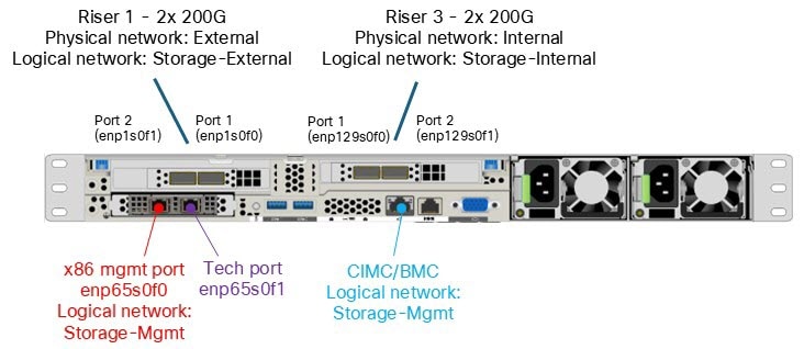
Internal cluster connectivity: enp129s0f0 and enp129s0f1
Cisco Nexus Hyperfabric uses NICs enp129s0f0 and enp129s0f1 for internal cluster communication between the Cisco EBox nodes (E-nodes). A bond0 interface in active-standby mode is also created using these two internal interfaces. On top of the bond, a VLAN 69 subinterface (bond0.69) is defined. In addition, per-NIC subinterfaces (enp129s0f0.69 and enp129s0f1.69) are also created.
This figure shows an example of internal connectivity to the storage switches Storage_Leaf1 and Storage_Leaf2.
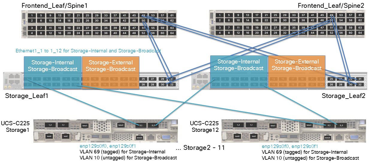
This information applies to the example in the illustration:
- There are 12 servers.
-
Logical network: Storage-Internal VLAN 69 (tagged)
- Anycast gateway (SVI) IP address: 172.16.128.254/24
- Network address: 172.16.128.0/24 This IP address must be non-routable.
- Inner VIP address on the Cisco EBox: 172.16.254.254
-
Logical network: Storage-Broadcast VLAN 10 (untagged)
- This logical network does not have an anycast gateway IP address.
- When you create a logical network, you must assign a VLAN to the network, even if the VLAN is untagged. The example uses VLAN 10.
- Ports 13 to 24 on the switches are reserved for Storage-Internal connectivity.
In the example configuration, bond0.69 has an extra IP address: 172.16.254.254/32. This was defined during cluster setup and is currently owned by Server 5, although it could move to another server. This IP address functions as the internal cluster virtual IP address used by the Cisco EBox services.
This example ip command output shows enp129s0f0 and enp129s0f1 configured for cluster communications and tagged with internal VLAN 69.
vastdata@svl-vc01-d-128-5 ~:$ ip -br a
lo                       UNKNOWN 127.0.0.1/8 ::1/128
enp65s0f0                UP      10.10.10.10/24 fe80::fl58:39e3:91d4:f252/64
enp65s0fl                DOWN    192.168.2.2/24 fe80::5032:3253:4d2b:fb05/64
enpl29s0f0               UP      fe80::4911:69e:fe86:6856/64 fe80::8725:7bee:4978:fc7c/64
enpl29sOfl               UP      fe80::4911:69e:fe86:6857/64 fe80::bl2a:ceea:9b3e:cfa6/64
enplsOfO                 UP      fe80::4911:69e:fe86:6226/64 fe80::8145:19e2:a768:941d/64
enplsOfl                 UP      fe80::4911:69e:fe86:6227/64 fe80::3beb:bd95:la35:e4ec/64
enpl29s0f3               UP      fe80::c522:9002:5f38:bl5a/64
enpl29s0f4               UP      fe80::9945:59b5:df87:c029/64
docker0                  DOWN    fe80::fc6e:78e4:lb0e:64f0/64
bond0                    UP      fe80::fc6e:78e4:lb0e:64f0/64
bond0.69@bond0           UP      172.16.128.5/18 172.16.254.254/32
                                 fe80::cfd7:355d:e26:2e4a/64
enpl29s0f0.69@enpl29s0f0 UP      172.16.0.5/18 fe80::cfd7:355d:e26:2e4a/64
enpl29s0fl.69@enpl29s0fl UP      172.16.64.5/18 fe80::cfd7:355d:e26:2e4a/64
ls0f0.200@enpls0f0       UP      10.198.54.144/25 10.198.54.170/25 10.198.54.158/25
                                 10.198.54.190/25 fe80::fc6e:78e4:lb0e:64f0/64
ls0fl.200@enpls0fl       UP      10.198.54.157/25 10.198.54.180/25 10.198.54.150/25
                                 10.198.54.191/25 fe80::fc6e:78e4:lb0e:64f0/64
This example ip command output shows enp129s0f0 and enp129s0f1 bonded with a subinterface.
vastdata@svl-vc01-d-128-5 ~:$ cat /proc/net/bonding/bondO
Ethernet Channel Bonding Driver: v3.7.1 (April 27, 2011)

Bonding Mode: fault-tolerance (active-backup)
Primary Slave: None
Currently Active Slave: enpl29sOf4
Mil Status: up
Mil Polling Interval (ms): 100
Up Delay (ms): 0
Down Delay (ms): 0
Peer Notification Delay (ms): 0

Slave Interface: enpl29s0f3
Mil Status: up
Speed: 200000 Mbps
Duplex: full
Link Failure Count: 1
Permanent HW addr: be:ef:3f:1c:4d:32
Slave queue ID: 0

Slave Interface: enpl29s0f4
Mil Status: up
Speed: 200000 Mbps
Duplex: full
Link Failure Count: 1
Permanent HW addr: be:ef:52:24:e8:da
Slave queue ID: 0
External connectivity: enp1s0f0 and enp1s0f1
Cisco Nexus Hyperfabric uses NIC ports enp1s0f0 and enp1s0f1 for external Cisco EBox connectivity, and the GPU servers use these ports to access the Cisco EBox storage. During cluster bringup, you choose a VLAN tag for these ports, which is VLAN 200 in the examples of this section.
This figure shows an example of external connectivity to the storage switches Storage_Leaf1 and Storage_Leaf2.
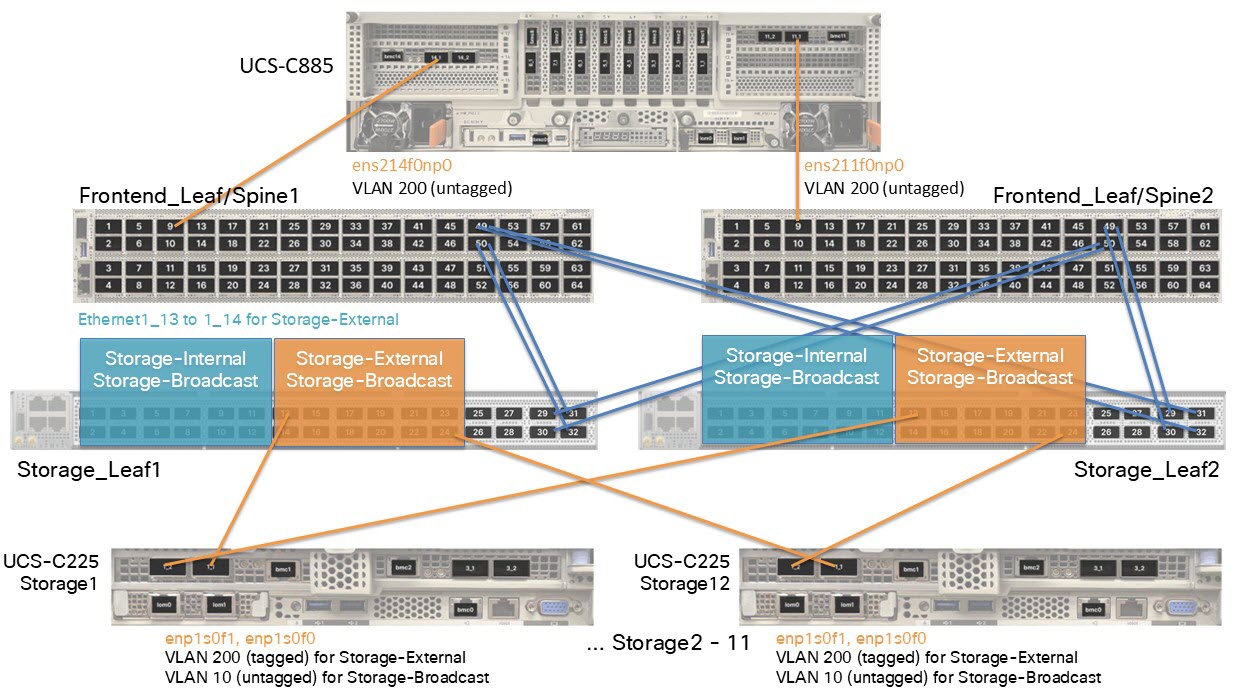
This information applies to the example in the illustration:
- There are 12 servers.
-
Logical network: Storage-External VLAN 200 (tagged)
- Anycast gateway (SVI) IP address: 10.198.54.129/25
- Network address: 10.198.54.128/25
-
Logical network: Storage-Broadcast VLAN 10 (untagged)
- This logical network does not have an anycast gateway IP address.
- Ports 13 to 24 on the switches are reserved for Storage-External connectivity.
Each interface is assigned multiple IP addresses from the external pool, which enables load balancing and path diversity for client traffic. This can occur because the GPU nodes see multiple IP endpoints.
This example ip command output shows enp1s0f0 and enp1s0f1 configured for external connectivity and tagged with external VLAN 200.
vastdata@svl-vc01-d-128-l ~:$ ip -br a
lo                       UNKNOWN 127.0.0.1/8 ::1/128
enp65s0f0                UP      10.10.10.10/24 fe80::fl58:39e3:91d4:f252/64
enp65s0fl                DOWN    192.168.2.2/24 fe80::5032:3253:4d2b:fb05/64
enpl29s0f0               UP      fe80::4911:69e:fe86:6856/64 fe80::8725:7bee:4978:fc7c/64
enpl29s0f1               UP      fe80::4911:69e:fe86:6857/64 fe80::bl2a:ceea:9b3e:cfa6/64
enpls0f0                 UP      fe80::4911:69e:fe86:6226/64 fe80::8145:19e2:a768:941d/64
enpls0fl                 UP      fe80::4911:69e:fe86:6227/64 fe80::3beb:bd95:la35:e4ec/64
enpl29s0f3               UP      fe80::c522:9002:5f38:bl5a/64
enpl29s0f4               UP      fe80::9945:59b5:df87:c029/64
docker0                  DOWN    fe80::fc6e:78e4:lb0e:64f0/64
bond0                    UP      fe80::fc6e:78e4:lb0e:64f0/64
bond0.69@bond0           UP      172.16.128.5/18 172.16.254.254/32
                                 fe80::cfd7:355d:e26:2e4a/64
enpl29s0f0.69@enpl29s0f0 UP      172.16.0.5/18 fe80::cfd7:355d:e26:2e4a/64
enpl29s0fl.69@enpl29s0fl UP      172.16.64.5/18 fe80::cfd7:355d:e26:2e4a/64
ls0f0.200@enpls0f0       UP      10.198.54.144/25 10.198.54.170/25 10.198.54.158/25
                                 10.198.54.190/25 fe80::fc6e:78e4:lb0e:64f0/64
ls0fl.200@enpls0fl       UP      10.198.54.157/25 10.198.54.180/25 10.198.54.150/25
                                 10.198.54.191/25 fe80::fc6e:78e4:lb0e:64f0/64
Management ports: enp65s0f0 and enp65s0f1
These are the management ports, which are also known as the LAN-on-Motherboard (LOM) ports.
|
Port |
Description |
|---|---|
|
enp65s0f0 |
This port is used for cluster bringup, management plane, and VAST GUI access. For example, the IP address 10.10.10.10/24, which is bolded in the example output, is the management IP address that you defined during setup. This IP address is currently hosted on VAST node 5, but may float to another node depending on the active management IP address. |
|
enp65s0f1 |
This port is reserved as the tech-support port and is typically not connected to any switch. This port is intended for direct crash cart access during field installation or troubleshooting. |
This example ip command output shows enp65s0f0 configured as the LOM 0 port.
vastdata@svl-vc01-d-128-5 ~:$ ip -br a
lo                       UNKNOWN 127.0.0.1/8 ::1/128
enp65s0f0                UP      10.10.10.10/24 fe80::fl58:39e3:91d4:f252/64
enp65s0fl                DOWN    192.168.2.2/24 fe80::5032:3253:4d2b:fb05/64
enpl29s0f0               UP      fe80::4911:69e:fe86:6856/64 fe80::8725:7bee:4978:fc7c/64
enpl29s0f1               UP      fe80::4911:69e:fe86:6857/64 fe80::bl2a:ceea:9b3e:cfa6/64
enpls0f0                 UP      fe80::4911:69e:fe86:6226/64 fe80::8145:19e2:a768:941d/64
enpls0fl                 UP      fe80::4911:69e:fe86:6227/64 fe80::3beb:bd95:la35:e4ec/64
enpl29s0f3               UP      fe80::c522:9002:5f38:bl5a/64
enpl29s0f4               UP      fe80::9945:59b5:df87:c029/64
docker0                  DOWN    fe80::fc6e:78e4:lb0e:64f0/64
bond0                    UP      fe80::fc6e:78e4:lb0e:64f0/64
bond0.69@bond0           UP      172.16.128.5/18 172.16.254.254/32
                                 fe80::cfd7:355d:e26:2e4a/64
enpl29s0f0.69@enpl29s0f0 UP      172.16.0.5/18 fe80::cfd7:355d:e26:2e4a/64
enpl29s0fl.69@enpl29s0fl UP      172.16.64.5/18 fe80::cfd7:355d:e26:2e4a/64
ls0f0.200@enpls0f0       UP      10.198.54.144/25 10.198.54.170/25 10.198.54.158/25
                                 10.198.54.190/25 fe80::fc6e:78e4:lb0e:64f0/64
ls0fl.200@enpls0fl       UP      10.198.54.157/25 10.198.54.180/25 10.198.54.150/25
                                 10.198.54.191/25 fe80::fc6e:78e4:lb0e:64f0/64
Install the VAST release bundle software on the storage servers
This procedure assumes that you have already installed and cabled the hardware, configured the logical networks, and performed basic server set up. For more information, see Cisco EBox storage cluster installation workflow.
Follow these steps to install the VAST release bundle software on the storage servers.
Step 1 | Connect to the second management port (tech support port) of the first server and assign an IP address in the same subnet, such as 192.168.2.254/24, to the machine that you used for the connection, then follow these substeps:
If you cannot use the second management port from an alternative host, then follow these substeps instead:
After the installer finishes discovery, you see a table of discovered servers. 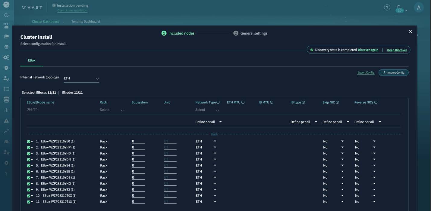
|
Step 2 | Verify that the table contains all expected servers. If you do not see all servers, that indicates an issue with cabling or switch configurations. |
Step 3 | Follow these substeps to update the table.
|
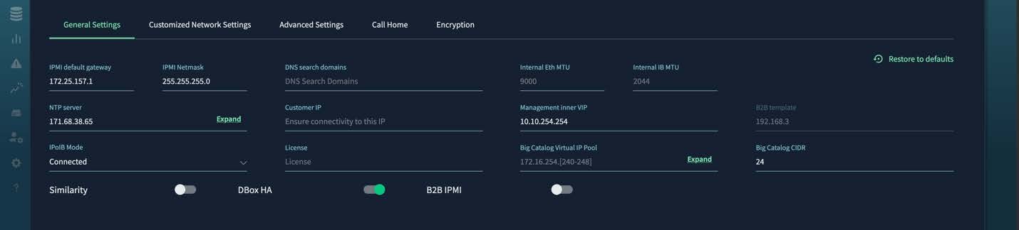
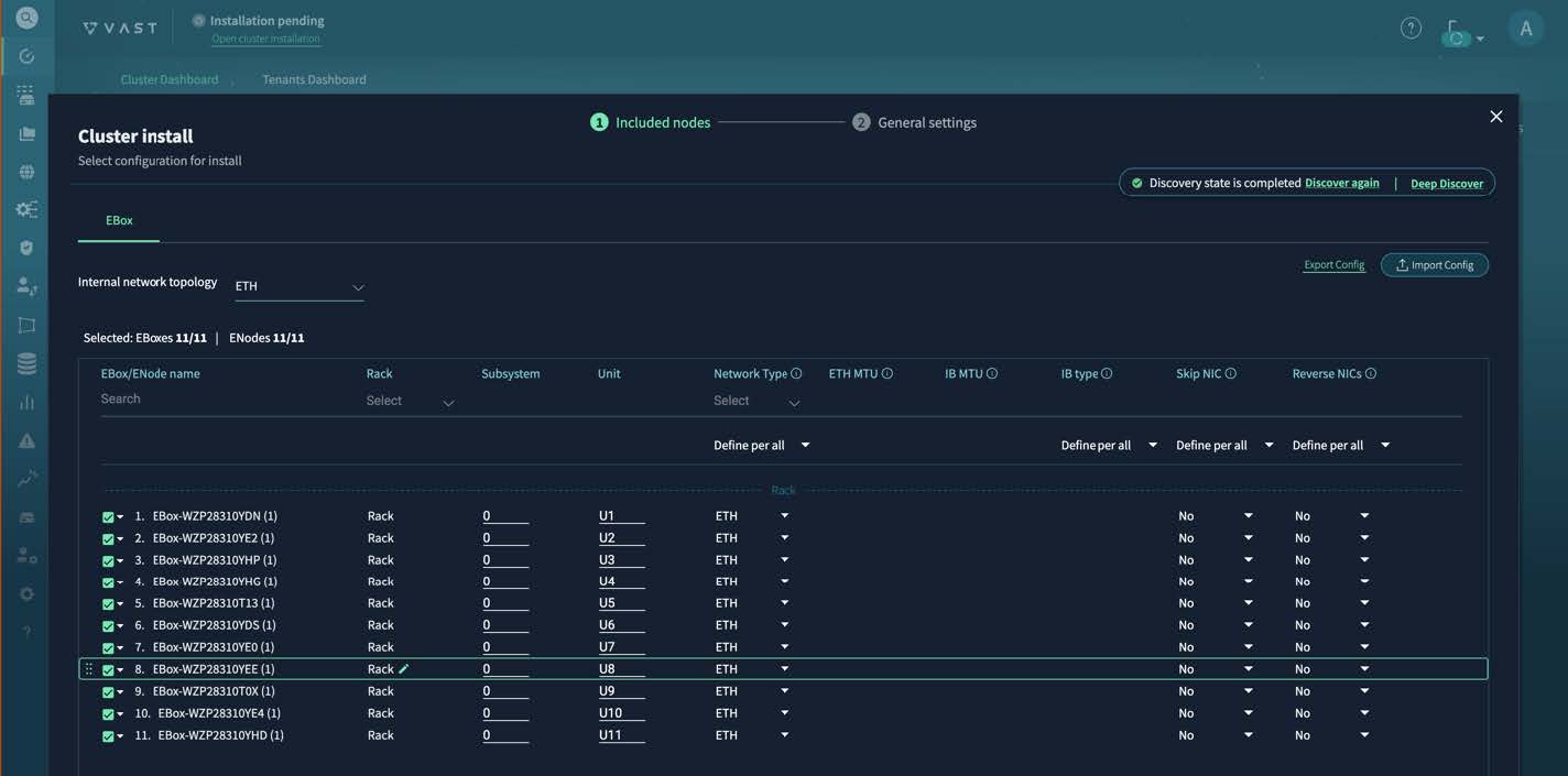
Step 4 | Configure the x86 and CIMC IP addresses, any additional IP address settings, the customized network settings for the internal network, and advanced settings. Fill out the fields as necessary, following some guidance specified here. On Cluster install page, for PSNT enter the same name as Cluster name. PSNT is an ID assigned by VAST after the software license is issued. Contact your Cisco customer representative to receive the ID. 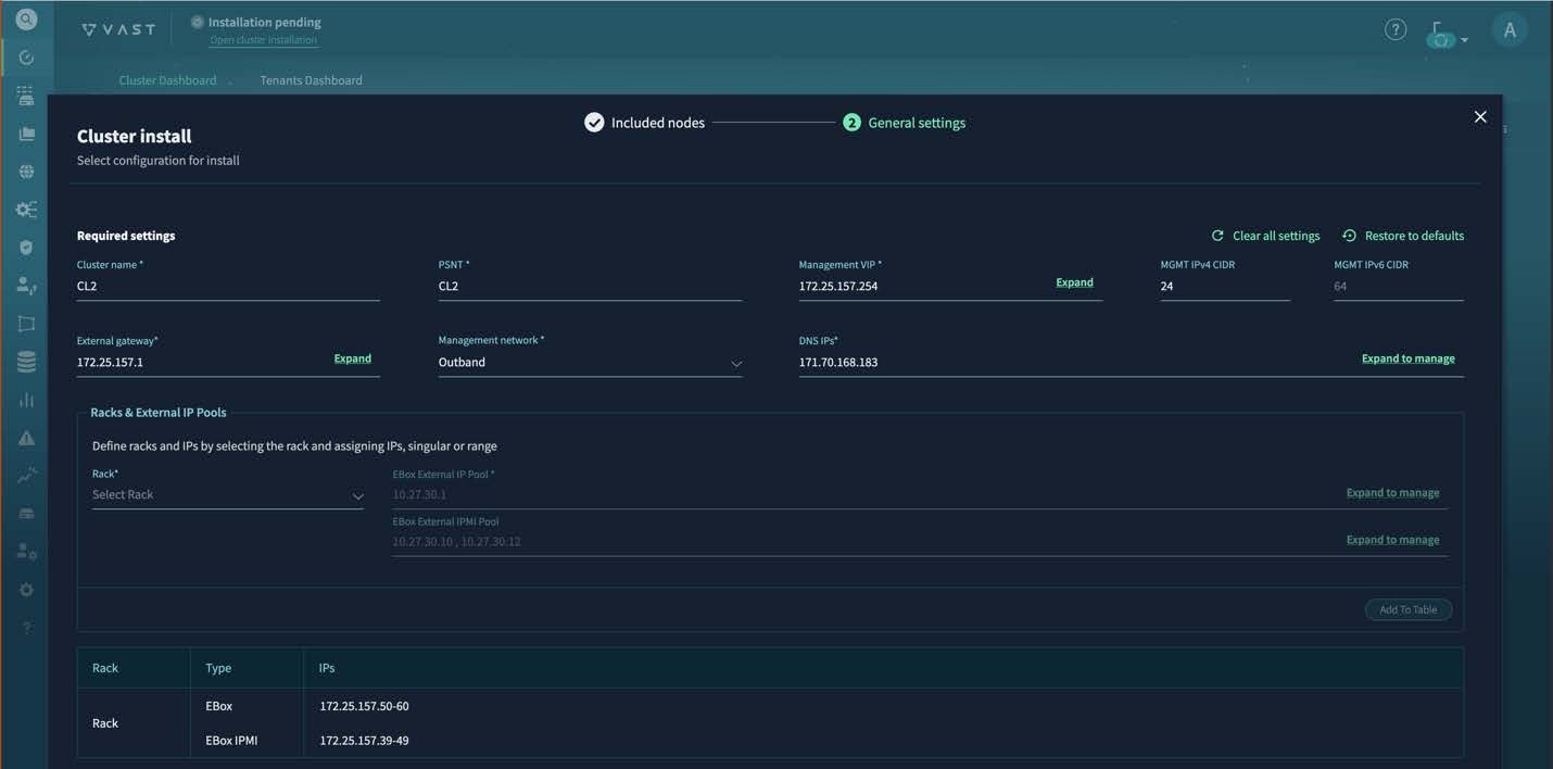
On the Customized Network Settings page for the internal network, for Selected QoS Type, select Priority Flow Control. 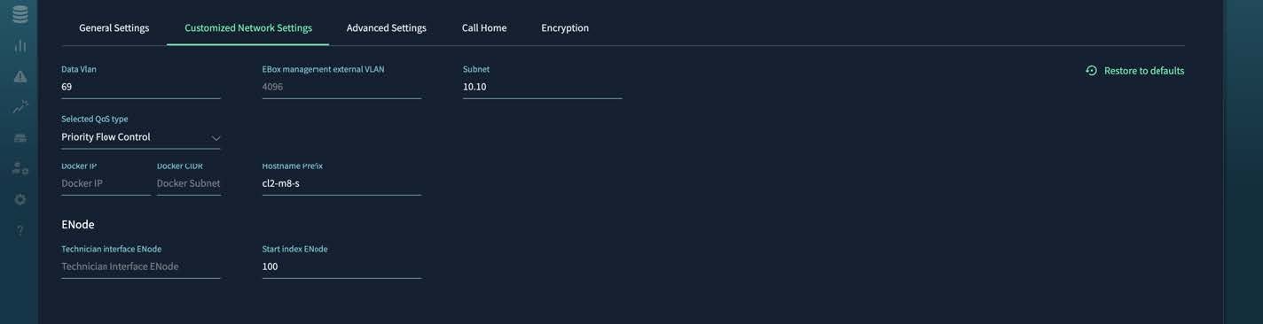
On the Advanced Settings page, specify these values:
|
Step 5 | Select Install Cluster. You can monitor the installation progress in the Activity tab on the left. The key milestones are "Cluster Deploy," "Cluster INIT," and "Cluster Activate." During the cluster deployment phase, you select an IP address from the management subnet that will become the VAST Management System (VMS) IP address, the VMS container reboots, and the GUI becomes permanently available at https://VMS_IP_address. You might also need to create a DNS entry to have a well-known service name or IP address to use for management purposes. After the installation reaches these milestones, the cluster transitions to the "Online" state. The dashboard looks similar to the screenshot, showing the expected count of inventory and storage capacity. 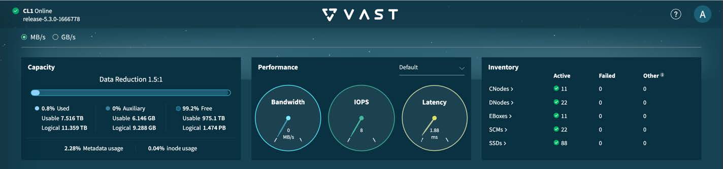
|
Perform server post-installation tasks
This procedure assumes that you installed the VAST release bundle software on the servers. For more information, see Install the VAST release bundle software on the storage servers.
Follow these steps to perform server post-installation tasks.
Step 1 | Complete the VAST release bundle software configuration to enable access from external clients, such as GPU servers or applications servers. This table shows the key tabs in which you must create or provision entities that external clients require for access.
For more information about VAST cluster administration, see the VAST Cluster Administrator's Guide. | ||||||||
Step 2 | (Optional) If your clusters need high read/write performance over NFS using RDMA, install the VAST Container Storage Interface (CSI) driver. For more information, see the VAST NFS User Guide.
|
Enable Quality of Service on the external ports of the servers (VMS releases 5.3.0 and 5.3.3)
In the VAST Management System (VMS) GUI, you must enable Quality of Service (QoS) on each storage server's external ports. This procedure is for VMS releases 5.3.0 and 5.3.3 and uses a combination of the VMS GUI and the server CLI.
Follow these steps to enable Quality of Service on the external ports of the servers.
Step 1 | Deactivate the storage cluster.
|
Step 2 | Use SSH to connect to one of the servers and view the contents of the /etc/vast-configure_network.py-params.ini file. The ini file must contain these settings: The third property is labeled "vxlan", but it also applies for IP fabric. If any of the setting values are not correct, perform these substeps.
|
Step 3 | Reactivate the storage cluster.
|
Step 4 | Repeat this procedure for each server. |
Enable Quality of Service on the external ports of the servers (VMS releases 5.3.5, 5.4.3, and later)
In the VAST Management System (VMS) GUI, you must enable Quality of Service (QoS) on each storage server's external ports. This procedure is for VMS releases 5.3.5, 5.4.3, and later and uses only the VMS GUI.
The configuration change will re-spawn containers serially. We do not recommend that you make these changes during cluster peak usage hours.
Follow these steps to enable Quality of Service on the external ports of the servers.
Step 1 | Navigate to . 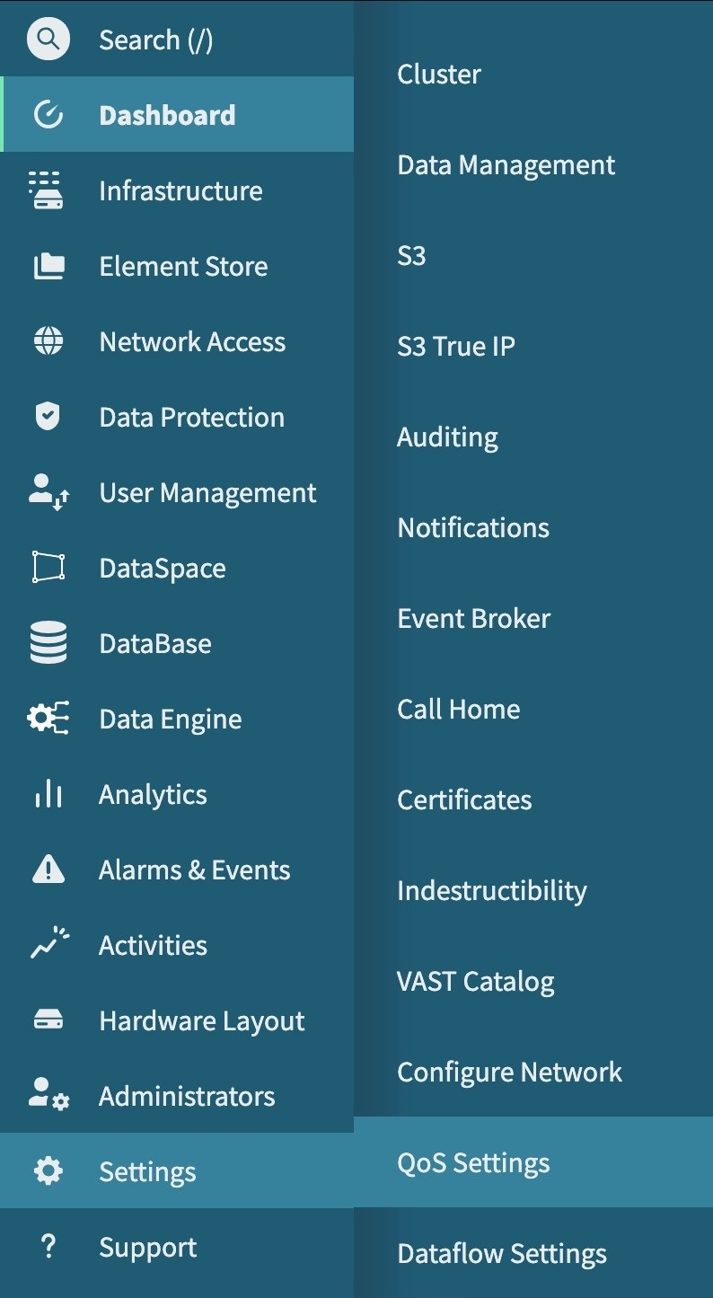
|
Step 2 | Update the QoS configuration. Use these settings for both internal and external network QoS:
These settings are for the DSCP & Mapping Section for both internal and external network QoS:
These settings are for External Network QoS:
These settings are for the DSCP & Mapping Section under External Network QoS:
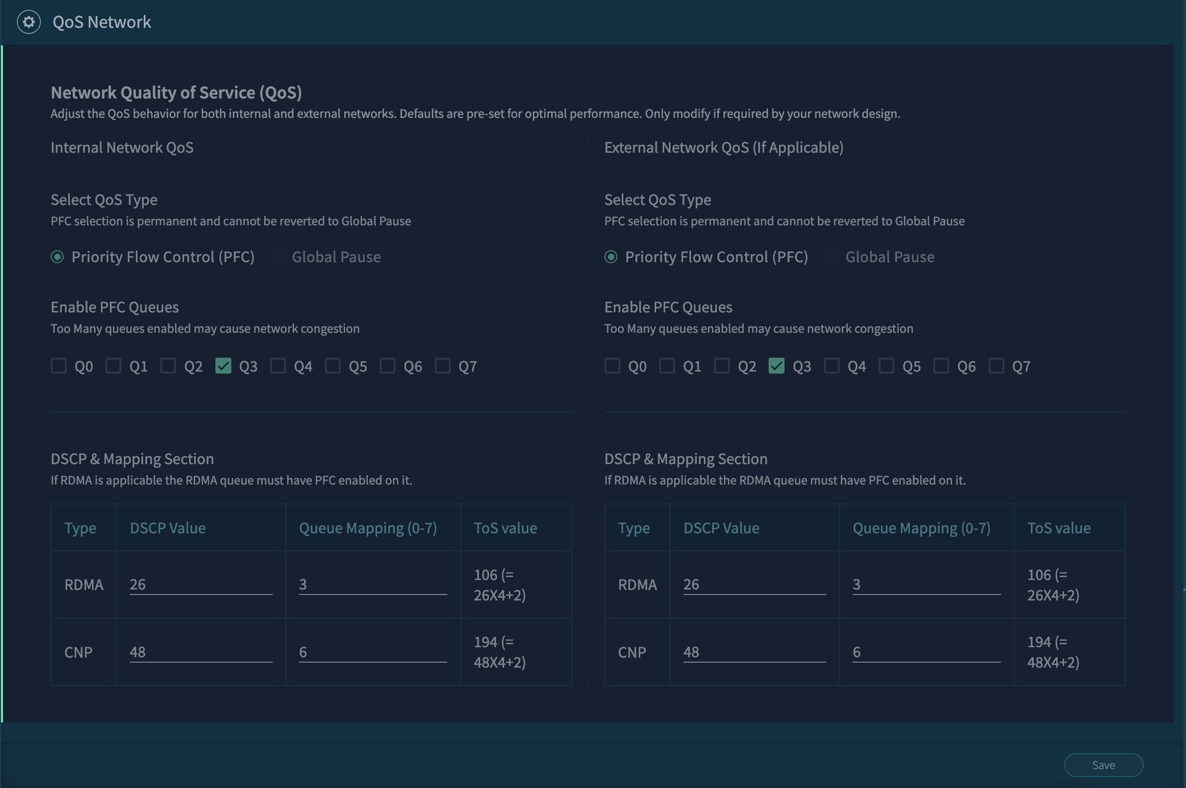
|
Step 3 | Select Save. |
Change the default user passwords
After you have set up a server, you should change the default user passwords.
Follow these steps to change the default user passwords.
Step 1 | In the VAST Management System (VMS) GUI, navigate to .
|
Step 2 | To change a Linux user or Intelligent Platform Management Interface (IPMI) pasword, use SSH to connect to one of the servers, then follow these substeps.
|
Guidelines for using a Cisco EBox storage cluster
These guidelines apply for using a Cisco EBox storage cluster:
- Use only the VAST Management System (VMS) for managing software on the server, including firmware upgrades. The VMS can properly orchestrate these processes to ensure high availability of the storage subsystem and maintain data integrity.
- Do not use Intersight to trigger operating system and firmware upgrades.
- Do not power cycle the cluster after it is up and running.
- Upgrade one server at a time.
Upgrading
Upgrade the VAST release bundle software
Follow these steps to upgrade the VAST release bundle software.
Step 1 | In the VAST Management System (VMS) GUI, navigate to . |
Step 2 | Select the hamburger icon and select VMS. 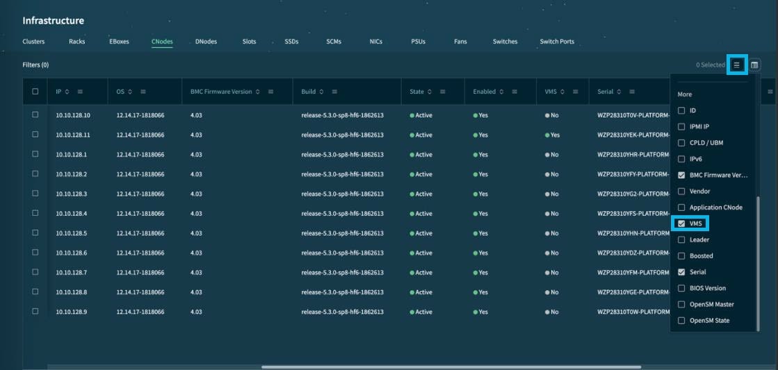
This displays the VMS column in the table. |
Step 3 | Find the VMS node that you want to upgrade in the table to get the IP address of the node. |
Step 4 | Use scp to copy the new release bundle to the VMS node's /vast/bundles directory. |
Step 5 | Use ssh to connect to the VMS node and execute these commands: |
Step 6 | In the VMS GUI, go to the Activities tab to view the status of the upgrade. |
Upgrade the operating system and firmware of the servers
After you upgrade the VAST Management System (VMS), you can perform a rolling upgrade of the operating system and firmware of the servers.
Follow these steps to upgrade the operating system and firmware of the servers.
Step 1 | In the VAST Management System (VMS) GUI, navigate to . |
Step 2 | Right select the cluster that you want to upgrade and select Upgrade. |
Step 3 | Select OS + FW, BMC Firmware, and Force, then select Upgrade Now. |
Step 4 | To monitor the status of the upgrade, navigate to Activities. This process takes almost 10 hours because the upgrade occurs in a non-disruptive manner with one server getting upgraded at a time. |
Expand a Cisco EBox storage cluster
After you deploy the initial cluster of 11 servers, you can expand the cluster with additional servers in increments of three.
Follow these steps to expand a Cisco EBox storage cluster.
Step 1 | Cable and power on the new servers. |
Step 2 | In the VAST Management System (VMS) GUI, navigate to . |
Step 3 | Select Add New EBoxes
|
Step 4 | Select Expand. The VMS starts the storage expansion process. After the VMS completes this process, all new EBoxes, CNodes, and DNodes will be in the "Activated" state. |
Create a support bundle
If you encounter an issue with the Cisco EBox storage cluster, create a support bundle and provide the bundle to Cisco EBox support personnel.
Follow these steps to create a support bundle.
Step 1 | In the VMS GUI, navigate to . |
Step 2 | Select Create Support Bundle.
|
Step 3 | After the support bundle task in the Activities tab is marked complete, download the support tarballs from the /userdata/bundles directory of every server.
|
Replacing hardware
Replace a failed server
Follow these steps to replace a failed server.
Step 1 | Physically replace the server, including cabling it and powering it on. |
Step 2 | In the VAST Management System (VMS) GUI, navigate to . |
Step 3 | Right select the EBox and select Replace. |
Replace a solid state drive in a server
Follow these steps to replace a solid state drive (SSD) in a server.
Step 1 | Physically replace the SSD. |
Step 2 | In the VAST Management System (VMS) GUI, navigate to . |
Step 3 | Right select the SSD that you replaced and select Activate. |
Replace a power supply unit in a server
If only one of the two power supply units (PSUs) fails, you can replace the failed PSU without powering down the server.
Follow these steps to replace a power supply unit in a server.
Step 1 | Physically replace the PSU. |
Step 2 | If you had to replace both PSUs, power up the server. |
Replace a network interface card in a server
Follow these steps to replace a network interface card (NIC) in a server.
Step 1 | In the VAST Management System (VMS) GUI, navigate to . |
Step 2 | Right select the server with the NIC that you will replace and select Deactivate. |
Step 3 | After the server is deactivated, right select the server and select Power off. |
Step 4 | After the server is powered off, replace the NIC. |
Step 5 | Right select the server and select Power on. |
Step 6 | After the server is powered on, right select the server and select Activate. |
Replace a fan in a server
Follow these steps to replace a fan in a server.
Step 1 | In the VAST Management System (VMS) GUI, navigate to . |
Step 2 | Right select the server with the fan that you will replace and select Deactivate. |
Step 3 | After the server is deactivated, right select the server and select Power off. |
Step 4 | After the server is powered off, replace the fan. |
Step 5 | Right select the server and select Power on. |
Step 6 | After the server is powered on, right select the server and select Activate. |
Replace an M.2 boot drive in a server
Follow these steps to replace an M.2 boot drive in a server.
Step 1 | In the VAST Management System (VMS) GUI, navigate to . |
Step 2 | Right select the server with the M.2 drive that you will replace and select Deactivate. |
Step 3 | After the server is deactivated, right select the server and select Power off. |
Step 4 | After the server is powered off, replace the M.2 drive. If both drives failed, then replace both of them. |
Step 5 | Right select the server and select Power on. |
Step 6 | After the server is powered on, right select the server and select Activate. If you replaced only one drive, the hardware RAID controller replicates the VAST operating system from the second drive to the new drive. However, if you replaced both drives or if the RAID controller is faulty, you must boot from PXE or VMedia and reinstall the VAST operating system. Contact your Cisco customer support representative for assistance. |