
Cisco Nexus Hyperfabric — Getting Started
Cisco Nexus Hyperfabric
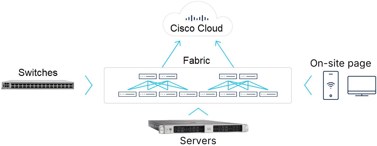
The Cisco Nexus Hyperfabric is a fabric-as-a-service solution that allows you to design and build a physical network that is managed by a cloud-based service. Your network can start as small as a single switch and can grow to multiple locations, each with a fabric of many switches.
The design, deployment, and operation of the Cisco Nexus Hyperfabric is based on a shared responsibility model between you and Cisco. Cisco automation and operations staff own the proper functioning of the cloud-based service and the software upgrade process. Your staff maintains direct control of the timing of switch upgrades and of all interconnections to your applications, hosts, domestic network, and connectivity to the cloud-based service.
Components of a Cisco Nexus Hyperfabric deployment
These components comprise a Cisco Nexus Hyperfabric deployment:
- Cisco Nexus Hyperfabric service: a scalable, globally-distributed, multi-tenant cloud-based software-as-a-service (SaaS) network infrastructure management solution. The Cisco Nexus Hyperfabric service is hosted and operated by Cisco, and is the single point of provisioning and visibility for your fabrics. Organizations are created within a specific geographic region, which determines where device telemetry and services reside.
- Cisco Nexus Hyperfabric switches: cloud-managed Cisco 6000 switches on your premises or in a colocation environment. Bootstrapping and administration of the switches is handled by the cloud-based service.
- High-performance fabrics: mesh or spine-leaf topologies that use EVPN VXLAN, Layer 2 VLANs, or IPv4/IPv6 routing.
- Graphical user interface (GUI) and the REST API: the interfaces that you can use to perform tasks in Cisco Nexus Hyperfabric.
- On-site page: provides the network cabling technicians with step-by-step tasks to claim, bind, and cable the devices in your fabric. This page also provides real-time validation of the fabric topology.
- Cisco UCS servers: (Optional) cloud-monitored Cisco UCSC-C225-M8N-1P servers for storage and Cisco UCSC-885A-M8-HC1 servers for GPUs on your premises or in a colocation environment. Bootstrapping and administration of the switches is handled by the cloud-based service.
How Cisco Nexus Hyperfabric works
This is the overall process of how Cisco Nexus Hyperfabric works:
- In collaboration with the Cisco Nexus Hyperfabric team, you design your fabric online using an automated design tool provided in the Cisco Nexus Hyperfabric GUI. The completed design is a blueprint for your new fabric.
-
When your fabric blueprint is complete, Cisco Nexus Hyperfabric generates these additional resources:
- A detailed bill of materials (BoM) for purchasing the necessary fabric components, including servers, switches, and pluggables such as optics, Direct Attach Cables (DACs), and Active Optical Cables (AOCs)
- A complete cabling plan for your installer to wire the fabric
- When you receive your components, your installer physically wires them as directed by the On-site page.
- Each new device contains an agent that allows it to contact Cisco Nexus Hyperfabric. You configure the management port of one switch and provide that port with an external Internet connection. That switch then contacts Cisco Nexus Hyperfabric. This Internet-connected switch is referred to as the "exit node".
- The agent enables each device to discover and authenticate its neighbors. As each device discovers a path to an exit node in the fabric, the device contacts the service through the exit node.
-
When your devices are connected and ready, you register ("claim") each device online with Cisco, specifying the organization that owns the device.
 NoteIn some cases, your devices might be received already claimed by your organization.
 - In Cisco Nexus Hyperfabric, you assign ("bind") each physical device to its logical location ("node") in the fabric blueprint. When you bind a device to a node in the blueprint, the device can download its configuration from Cisco Nexus Hyperfabric.
- After the fabric has been fully provisioned, you can connect your local hosts and servers to the fabric.
Device telemetry
Cisco Nexus Hyperfabric provides nearly real-time telemetry for these device stats:
- Switch or server: port status, assertions, and traffic stats
- Interface: port counters, link status, and network configuration
- Environmental: per switch sensor readings for fans, PSUs, and other components
- Optics and pluggables: digital optical monitoring (DOM) statistics
Nexus Hyperfabric use cases
Typical use cases for Cisco Nexus Hyperfabric include small to medium branch offices or remote colocation sites where you do not want on-premises management. The Cisco Nexus Hyperfabric is ideal for meeting needs such as
- deploying or extending new data center fabrics or easily building new data center fabrics
- deploying reliably and rapidly with basic network requirements and compute connectivity
- designing new data center networks easily and evolving them over time
- deploying small, spineless fabrics of one or two switches
- deploying new fabrics for AI clusters easily
- deploying seamlessly and extending distributed data centers to edge or co-locations, and
- starting small and expanding fabrics seamlessly without confined architectures.
Supported topologies
Cisco Nexus Hyperfabric supports these network topologies:
- A single switch or a redundant switch pair
- A small mesh network
- A spine and leaf fabric
- A multi-tier fabric
A growing site could change the topology as needed by revisiting the design tool in Cisco Nexus Hyperfabric and creating an updated blueprint.
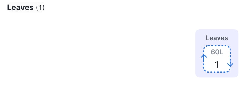
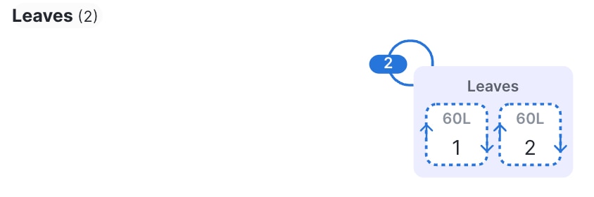
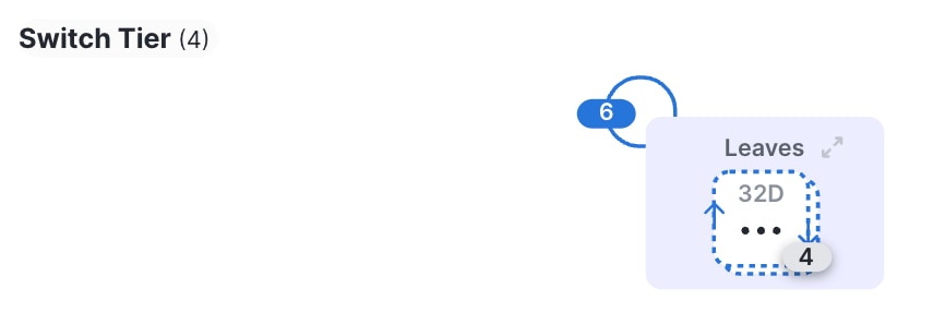
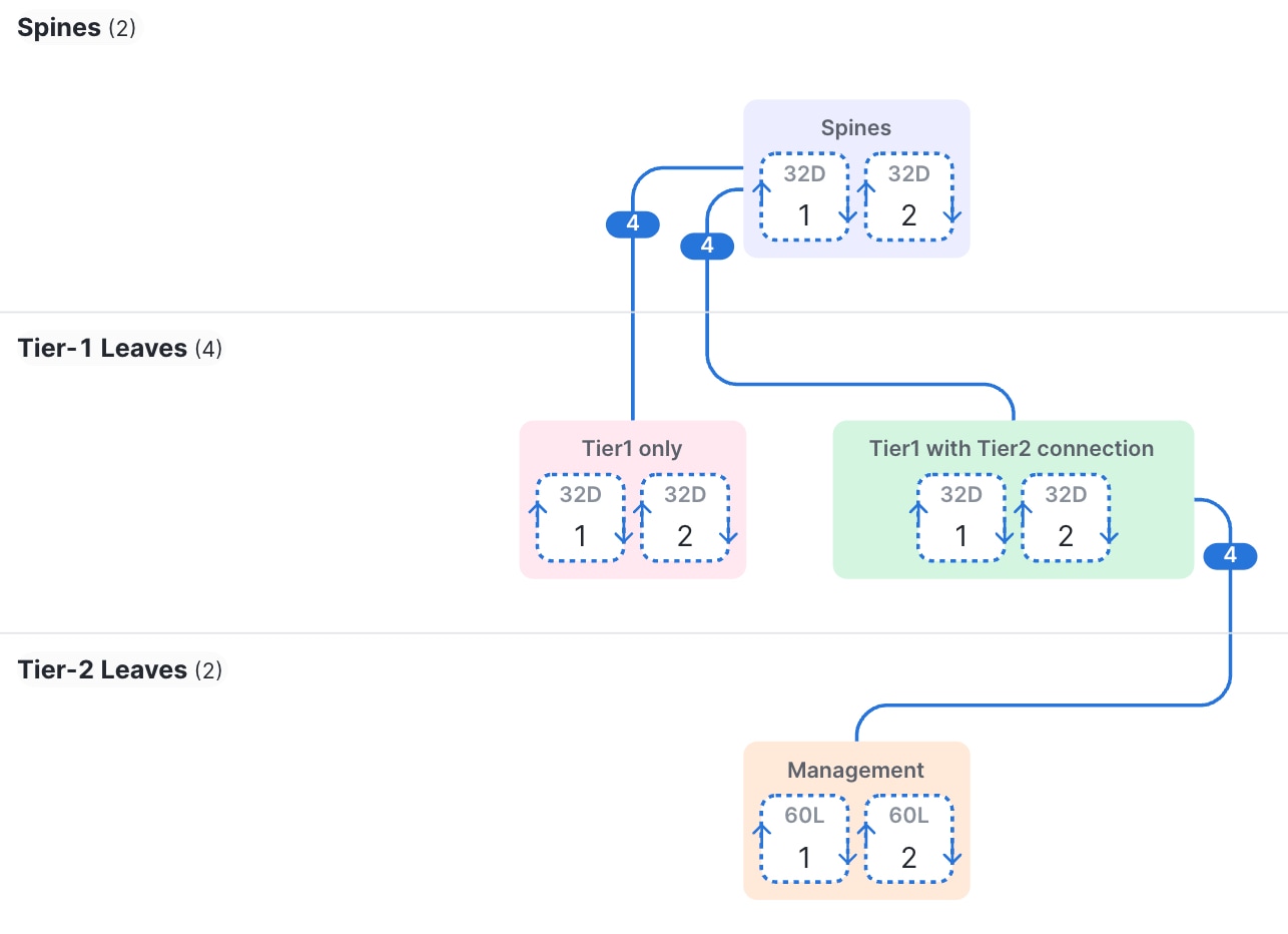
The illustrations in the topology subections show cable connections as colored lines joining different device groups. Each number on a cable indicates the number of connections between device groups.
Single leaf switch or redundant pair
In a site with fewer than 50 hosts, a single leaf switch may be sufficient. For high availability, you can deploy a second switch in a redundant configuration.
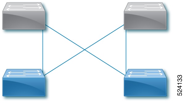
Small mesh fabric
A small mesh fabric has two to five interconnected leaf switches.
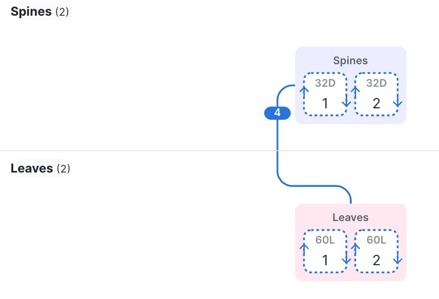
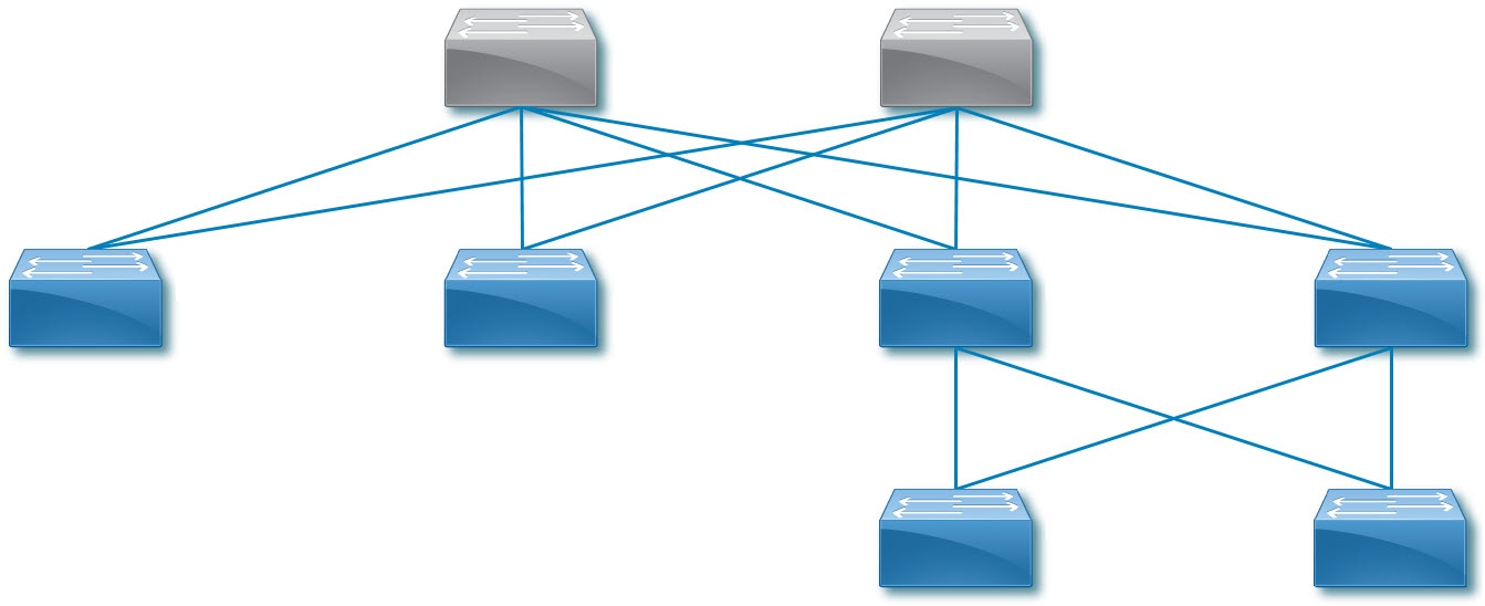
Spine and leaf fabric
A spine and leaf fabric can be a 2-tier topology that has one to four spine switches as the first tier and one or more leaf switches as the second tier. You can also have a 3-tier topology, in which you have additional leaf switches as the third tier connected to the second tier leaf switches.
The Cisco Nexus Hyperfabric lifecycle
To design, deploy, and maintain a network based on the Cisco Nexus Hyperfabric, you will work together with Cisco to follow the process illustrated in Cisco Nexus Hyperfabric lifecycle .
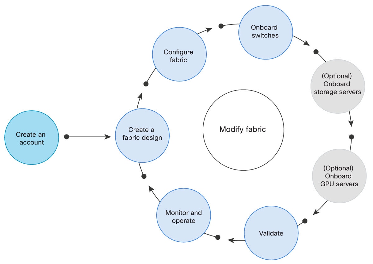
- Log in to Cisco Nexus Hyperfabric. The first step in creating your cloud-managed network is logging in to the Cisco Nexus Hyperfabric portal and creating an organization in which you will design and operate your network fabric. See Log into Cisco Nexus Hyperfabric.
- Create a fabric design. In Cisco Nexus Hyperfabric, you will design your fabric using the Blueprint Designer, selecting the devices and the topology to create a blueprint of your fabric. See Designing the fabric blueprint.
- Configure (or modify) the fabric. In the Blueprint Designer, configure the interconnections between the fabric devices. Configure the pluggables such as optics, Direct Attach Cables (DACs), and Active Optical Cables (AOCs), and configure the remaining ports for connection to servers and other network devices. See Modify a fabric.
- Onboard the switches. When the Nexus Hyperfabric switches have been physically installed and wired according to the blueprint, they must be "claimed" by the organization and "bound" to their logical positions (nodes) in the blueprint. The switches will become cloud-managed through the Cisco Nexus Hyperfabric portal. See Onboard a fabric.
- (Optional) Onboard the servers. When the servers have been physically installed and wired according to the blueprint, they must be "claimed" by the organization and "bound" to their logical positions (nodes) in the blueprint. The servers will become cloud-monitored through the Cisco Nexus Hyperfabric portal. See Onboard a fabric.
- Validate the design. After you bind the switches to the fabric blueprint, verify that traffic is being forwarded correctly.
- Monitor and operate the fabric. See Cisco Nexus Hyperfabric — Configure Fabrics .
Accessing Cisco Nexus Hyperfabric
Log into Cisco Nexus Hyperfabric
To get started in the design of your cloud-managed network, log into Cisco Nexus Hyperfabric.
You must have a cisco.com user account to log into Nexus Hyperfabric, which you can create at https://id.cisco.com/.
Follow these steps to log into Cisco Nexus Hyperfabric.
Step 1 | Point your Web browser to https://hyperfabric.cisco.com/. |
Step 2 | For Email, enter the email address that you registered with https://id.cisco.com/, then select Continue to cisco.com. You will be authenticated by Cisco's Single Sign-On (SSO) service. The Nexus Hyperfabric account is in addition to a cisco.com user account. 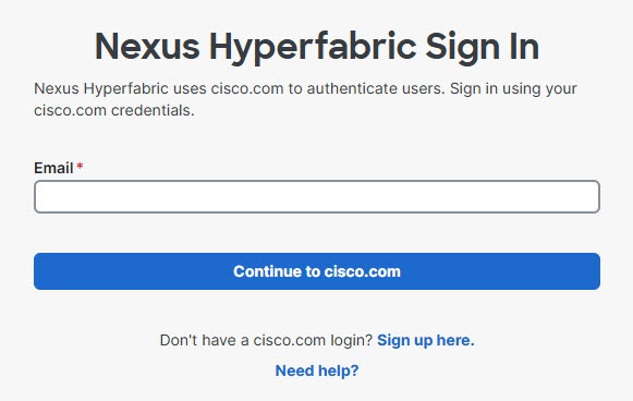
If you already are an administrator in one or more Nexus Hyperfabric organizations, you will be taken the main page of the organization you logged into last.
|
Step 3 | If you are not the administrator for an existing organization, Nexus Hyperfabric prompts you to create one. 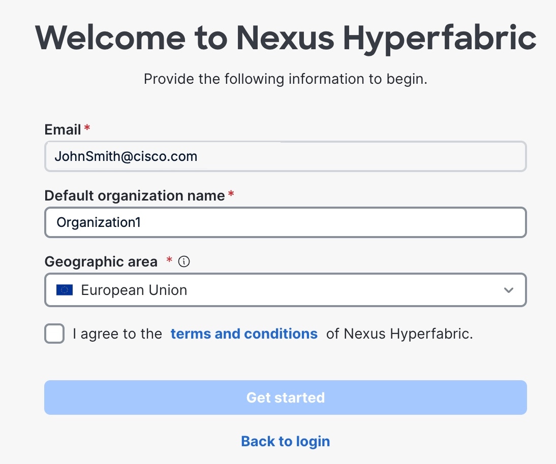
|
Add a new user
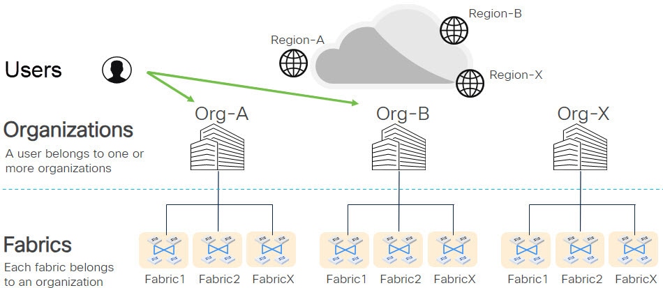
If you are an administrator for an organization, you can add a new user to that organization. A user can belong to multiple organizations. Users and organizations illustrates the association of users and organizations.
Follow these steps to add a new user.
Step 1 | Choose . 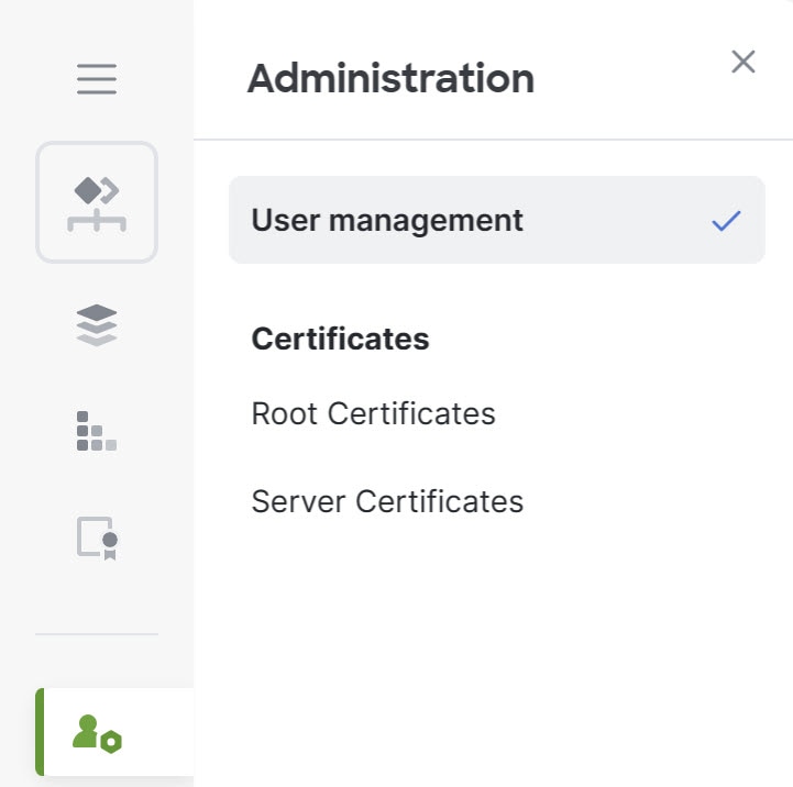
|
Step 2 | Select + Add User. 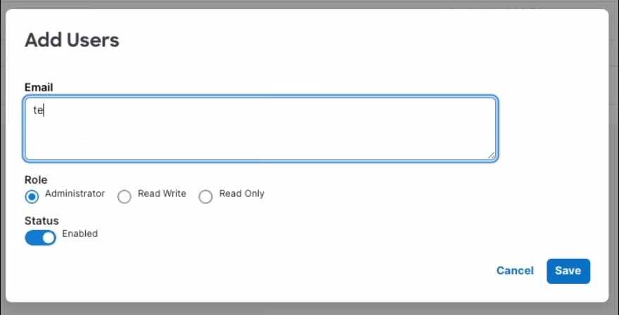
|
Step 3 | Enter the email addresses of the new users. You can enter a comma-separated list of email addresses. The role and status settings you select will apply to all users in this list. |
Step 4 | Select a role: Administrator, Read Write, or Read Only. |
Step 5 | Select the status of the users: Enabled or Disabled. |
Step 6 | Select Save. |
Identity provider federations
An identity provider (IdP) federation enables you to specify an IdP to use for single sign-on capability when logging into Cisco Nexus Hyperfabric. After you configure an IdP federation to use a specific domain, all users that are part of that domain can log into Nexus Hyperfabric using their regular (non-Cisco Connected Online) ID that they have with your company. These users have access to your company's Nexus Hyperfabric organization.
Limitations for identity provider federations
These limitations apply for identity provider (IdP) federations:
- A federated user cannot create an organization, regardless if the user is an administrator.
- A federated user cannot create an API bearer token. If you need a bearer token, contact a Cisco administrator within your organization to create one for you.
- Organizations in the European Union (EU) region do not support IdP federations.
Configure an identity provider federation
Follow these steps to configure an identity provider federation.
Step 1 | Add an authentication protocol. See the procedure for the authentication protocol that you want to add. |
Step 2 | |
Step 3 | Add a routing rule for an identity provider federation. Repeat this step if you want to configure multiple routing rules. |
Step 4 | Log into your identity provider (IdP) and add the users whom you want to be able to log into Nexus Hyperfabric using this IdP. See the documentation for your IdP for how to add users. |
Step 5 |
Add SAML as an authentication protocol
This procedure adds Security Assertion Markup Language (SAML) as an authentication protocol in Cisco Nexus Hyperfabric for use as an IdP federation. The procedure provides steps for using Microsoft Entra as the IdP as an example. You can use the IdP of your choice by substituting the Microsoft Entra-specific information as appropriate for your IdP. See your IdP's documentation for the exact steps.
NoteThe Microsoft Entra steps are subject to change without notice.
Follow these steps to add SAML as an authentication protocol.
Step 1 | Collect the service provider details from Nexus Hyperfabric.
| ||||||||||||
Step 2 | In your IdP, create a new Enterprise application for Nexus Hyperfabric. Follow these substeps for Microsoft Entra.
| ||||||||||||
Step 3 | Set up single sign-on with SAML. Follow these substeps for Microsoft Entra.
| ||||||||||||
Step 4 | Configure user attributes and claims. Follow these substeps for Microsoft Entra.
| ||||||||||||
Step 5 | Set up user groups. Follow these substeps for Microsoft Entra.
| ||||||||||||
Step 6 | Assign the user groups to the Nexus Hyperfabric application. Follow these substeps for Microsoft Entra.
| ||||||||||||
Step 7 | Download the federation metadata XML certificate file from your IdP. Follow these substeps for Microsoft Entra.
| ||||||||||||
Step 8 | In Cisco Identity, go to .
|
Add OpenID Connect as an authentication protocol
This procedure adds OpenID Connect as an authentication protocol in Cisco Nexus Hyperfabric for use as an identity provider (IdP) federation. The procedure provides steps for using Microsoft Entra as the IdP as an example. You can use the IdP of your choice by substituting the Microsoft Entra-specific information as appropriate for your IdP. See your IdP's documentation for the exact steps.
NoteThe Microsoft Entra steps are subject to change without notice.
Before following this procedure, configure OpenID Connect for use with Nexus Hyperfabric. See your IdP documentation for how to configure it.
Follow these steps to add OpenID Connect as an authentication protocol.
Step 1 | Collect the service provider details from Nexus Hyperfabric.
|
Step 2 | In your IdP, create a new Enterprise application for Nexus Hyperfabric. Follow these substeps for Microsoft Entra.
|
Step 3 | Collect information about the application that you created. Collect the client ID and discovery URL. Follow these substeps for Microsoft Entra.
|
Step 4 | Configure the client secret. Follow these substeps for Microsoft Entra.
|
Step 5 | Configure the redirect URI. Follow these substeps for Microsoft Entra.
|
Step 6 | Configure the application roles. Follow these substeps for Microsoft Entra.
|
Step 7 | Assign users or groups to the application roles. Follow these substeps for Microsoft Entra.
|
Step 8 | Configure applications roles to be included in the token. This step is not required for Microsoft Entra, as Microsoft Entra includes application roles in the
|
Step 9 | Configure API permissions. Follow these substeps for Microsoft Entra.
|
Step 10 | In Nexus Hyperfabric, choose . |
Step 11 | Select Launch admin portal. The Cisco Identity site opens in a new tab. |
Step 12 | In Cisco Identity, go to .
|
Add a domain for an identity provider federation
Follow these substeps to add a domain for an identity provider federation.
Step 1 | If you do not already have Cisco Identity open in your browser, follow these substeps.
|
Step 2 | In Cisco Identity, go to .
|
Add a routing rule for an identity provider federation
Follow these steps to add a routing rule for an identity provider federation.
Step 1 | If you do not already have Cisco Identity open in your browser, follow these substeps.
|
Step 2 | In Cisco Identity, go to .
|
Verify the identity provider federation configuration
After you have completed configuring your desired identity provider (IdP) and Cisco Identity for your new IdP federation, you can run a test to ensure that your federation works properly.
Follow these steps to verify the identity provider federation configuration.
Step 1 | In Cisco Identity, go to . |
Step 2 | Select the IdP that you added. |
Step 3 | In the pane that appears on the right, select . The test will inform you if there are any issues with the configuration. |
Common troubleshooting scenarios for identity provider federations
These are some common troubleshooting scenarios for identity provider (IdP) federations.
After creating an IdP federation, I can no longer log into Nexus Hyperfabric
Most likely, you misconfigured something, such as either forgetting to add the custom claim or entering the claim incorrectly. You can log into Nexus Hyperfabric using your cisco.com email address to bypass the misconfigured IdP federation by prefixing your email address with "cisco/". For example, "cisco/myEmailAddress@cisco.com". After logging in, fix the configuration.
All Nexus Hyperfabric administrators got removed from the remote IdP or the only administrator for your Nexus Hyperfabric organization is no longer an active user
You must have at least one Nexus Hyperfabric administrator in your organization. To resolve this issue, log into your remote IdP and either add a new administrator or upgrade an existing user to the administrator role.
Create a new organization
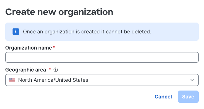
Follow these steps to create an organization.
Step 1 | Choose . |
Step 2 | Enter the name of the new organization. |
Step 3 | Select the region in which the organization resides. You can select either European Union (EU) or United States (US). The region determines where the device telemetry and services for the organization are stored and processed. |
Step 4 | Select Save. |
Region-based organizations
A region-based organization is a Nexus Hyperfabric organization that
- is bound to a single geographic region at the time of creation
- stores and processes its device telemetry and services within that region only, and
- helps you align with regional data handling requirements.
Cisco Nexus Hyperfabric supports these regions for organization creation:
- European Union (EU)
- United States (US)
How to identify an organization's region
The organizations list shows a region icon next to each organization name. Use the icon to quickly tell apart which region an organization resides in.
|
Region icon |
Region |
|---|---|
 |
European Union |
 |
United States |
Guidelines for creating an organization
Follow these guidelines when you create an organization in Cisco Nexus Hyperfabric.
Organization name guidelines
The organization name must meet these requirements:
- The name must be between 3 and 120 characters.
-
You can include these special characters in the name, as long as they are not the first or last character:
- -
- _
- +
- (space)
- /
- @
- .
- &
Organization region guidelines
Follow these guidelines when you select the region for an organization:
- Select the region based on where you want the organization's telemetry and service data to reside.
- Cisco Nexus Hyperfabric supports identity provider federation only for organizations in the US region. If you create an organization in the EU region, users must log in with their cisco.com credentials.
 Caution
You cannot change the region after you create the organization.
The region you select applies to the organization permanently. To have your fabrics, devices, or telemetry data reside in a different region, you must create a new organization in that region.
Organization limits and ownership
These limits and ownership rules apply to organizations:
- You can create up to 10 organizations.
- You cannot delete an organization after you create it.
- You are by default an administrator of any organization that you create.
User settings
Explains how to use bearer tokens for REST API authorization and change the default time zone and time format for a user.
Bearer tokens
Bearer tokens grant you authorization to use the Cisco Nexus Hyperfabric REST API calls. For more information about bearer tokens, as well as how to create them, see Cisco Nexus Hyperfabric API Authentication on Cisco DevNet.
Change the default time zone for user
You can choose the preferred time format and time zone you see in Cisco Nexus Hyperfabric. By default, Nexus Hyperfabric displays timestamps based on your browser's local time zone.
Step 1 | Select your username in the upper right of the GUI. |
Step 2 | From the Timezone drop-down list, select the time zone you wish to see. |
Step 3 | Set the time format to 12hr or 24hr. |
All timestamps in the GUI display the new time zone and format.
Data sharing with other applications
Describes how to share basic device inventory, telemetry, and notification data from Nexus Hyperfabric with other applications.
Share data with Cisco Cloud Control
Step 1 | Choose . |
Step 2 | Enable data sharing. |
Designing the fabric blueprint
When you have created a new organization or need to add a fabric to an existing organization, you can use the Blueprint Designer in the Cisco Nexus Hyperfabric to create a blueprint for the new fabric.
For supported fabric topologies, see Nexus Hyperfabric use cases.
The procedures for additional configuration, including port channels, logical networks, and routing tables, are described in other Cisco Nexus Hyperfabric articles.
Create a fabric using a template
You can create a fabric using a template, which has a predefined topology. You select a template based on the size of the fabric that you want to create.
Follow these steps to create a fabric using a template.
Step 1 | Choose Fabrics. |
Step 2 | Select + Add new fabric and select New from template. |
Step 3 | On the Templates page, select AI clusters or Switch fabrics as appropriate. |
Step 4 | Select the template with the topology that you want. |
Step 5 | If you want to change the default fabric name, select edit ( |
Step 6 | Modify the topology as appropriate, then select Save fabric blueprint. |
 ) next to the name, enter a new name, and select
 Create a fabric without using a template
Follow these steps to create a fabric without using a template.
Step 1 | Choose Fabrics. |
Step 2 | Select + Add new fabric and select New fabric.
|
Step 3 | Follow these substeps to configure the switch tiers.
To design a single-switch fabric or a mesh fabric with a switch model, create only one switch group. If you need to add another switch model, add another switch group. For example, you can have two switch groups—one for spine switches and one for leaf switches—to create a spine and leaf topology. As you make your switch choices, Cisco Nexus Hyperfabric updates the topology. |
Step 4 | In the Switch groups area of Group connections, select a box to configure the connections between the corresponding switch groups. The connections between the switch groups are displayed in a matrix of boxes. The matrix defines how the switches are connected to one another. The top and side labels show the names of the switch groups; the labels match on both axes. Each box shows the number of connections per switch group pair and is labelled with a letter such as A, B, or C. The Connections property specifies the number of connections, which you can change as indicated in the substeps. Each letter indicates a unique pair of switch PIDs, which can help you to identify outliers or misconfigurations quickly. The switches of the switch group specified by the left label are connected under the switches of the switch group indicated by the top label. The exception is if the switch group is the same on both axes, in which case the switches of that group are interconnected. As an example, assume you have two switches in a switch group named "Spine", four switches in another switch group named "Leaf", and you specify "2" for Connections between the groups. This means you have eight pairs of switches. Because you specified two connections, you have 16 total connections between the groups. After you select a box, the right side of the Switch groups area shows the properties of the group connections. You can select multiple boxes to see each of those group connections at the same time. For a selected switch group's connections, perform these substeps.
|
Step 5 | If your fabric will contain servers, follow these substeps.
|
Step 6 | Select Save fabric blueprint. The Saving fabric blueprint dialog appears and informs you that Cisco Nexus Hyperfabric generated the blueprint. |
Step 7 | If you want Cisco Nexus Hyperfabric to create the cabling plan now, select Run cabling. Otherwise, select Continue to topology. |
Modifying fabrics
If you have administrator or read-write access to the organization, you can modify the design of an existing fabric on the Fabrics page. You can make changes to the fabric blueprint at any stage: from an undeployed fabric design to an installed and running fabric.
The Fabrics blueprint page operates in one of two modes:
- Edit mode: This is the default mode for a user with administrator or read-write access. All fabric edit options are exposed.
- Running mode: This is the default mode for a user with read-only access. Settings and status are displayed, but no edit options are exposed. You can switch to edit mode only if you have administrator or read-write access.
All configuration procedures in this document assume that you are logged in with administrator or read-write access, and that the menus are in edit mode.
Modify a fabric
This procedure provides the typical workflow for making fabric configuration changes.
Follow these steps to modify a fabric.
Step 1 | Choose Fabrics, then click the fabric that you want to configure. |
Step 2 | If the fabric is not in the edit mode, click Switch to edit mode. |
Step 3 | Make your changes. NoteYour changes are not applied to the fabric until you review, commit, and push them. |
Step 4 | When you're ready to apply your changes, click Review configuration. 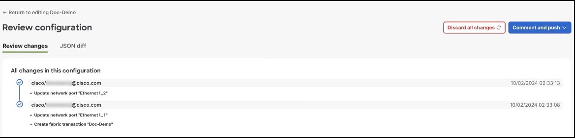
In the Review configuration page, you can view a list of brief descriptions of the changes since the last push, including the author's ID and the date and time when the change was saved. |
Step 5 | When you have reviewed the changes and are ready to apply them, click Comment and push. |
Step 6 | In the Comment before pushing configuration dialog box, enter the reason for the change. |
Step 7 | Click Push configuration. |
Step 8 | View the status of your changes. On the Fabrics blueprint page, view the fabric card to see the status of the pushed changes. Your changes may take some time to apply or they might generate red assertions. For example, if you push changes to an installed and running fabric, and the changes conflict with the physical cabling of the fabric, an assertion is raised. |
Deploying your fabric on site
The Cisco Nexus Hyperfabric greatly simplifies cabling operations of the switches in a fabric by providing features to guide tasks that you or a network cabling technician must perform on site. A network administrator uses Cisco Nexus Hyperfabric to create a blueprint that includes a cabling plan for the switches. You can view and follow tasks to set up the physical fabric topology or track the progress by going to a dedicated on-site page.
Alternatively, the network administrator can give a URL for the Cisco Nexus Hyperfabric on-site mobile-friendly site to the network cabling technicians. The technicians then open the URL on a mobile device to view the blueprint and follow that to set up the physical fabric topology or to view the status of the fabric.
For more information about deploying your fabric on site, see Cisco Nexus Hyperfabric — Deploying Your Fabric on Site.
Get the shareable link to the Cisco Nexus Hyperfabric on-site mobile-friendly site
Step 1 | In the Cisco Nexus Hyperfabric GUI, choose Fabrics, then select the fabric for which you want to get the link. |
Step 2 | Select On-site |
Step 3 | Select Shareable link. |
Step 4 | Go to the on-site mobile friendly site using one of these methods.
|
Cabling
Cisco Nexus Hyperfabric automatically determines how you should cable the devices in a fabric based on the number of connections per device pair and cabling strategy. The cabling strategy comprises two notions.
The first notion comprises these things:
- Strict: Cisco Nexus Hyperfabric connects each device pair with the number of connections that you selected. If a device does not have enough available ports for any reason, Cisco Nexus Hyperfabric indicates that there is an error with the cabling.
- Best effort: Cisco Nexus Hyperfabric connects each device pair with the number of connections that you selected if possible. However, if a device does not have enough available ports for any reason, Cisco Nexus Hyperfabric connects the devices in the pair to other devices in the same switch group that have enough available ports.
The second notion comprises these things:
-
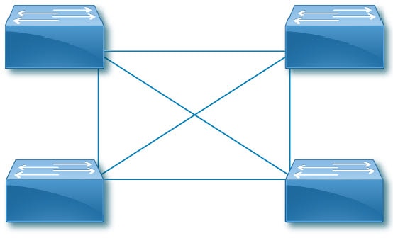
Dense: Cisco Nexus Hyperfabric connects consecutive ports of a device to consecutive ports of a paired device. The number of consecutive ports is equal to the number of connections per device pair that you selected. Cisco Nexus Hyperfabric repeats this connecting of consecutive ports for each successive paired device. This is used for switch-to-switch connections.
Switch-to-switch dense cabling strategy with two spine switches and two leaf switches 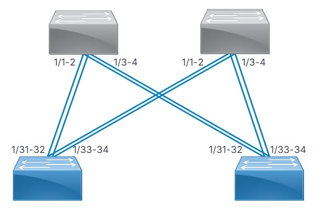
-
Distributed: Cisco Nexus Hyperfabric connects the first network interface card (NIC) of the first server to the first port of the first switch, then the second NIC of the server to the first port of the second switch, and so on until the server has one connection to the first port of each switch. Cisco Nexus Hyperfabric repeats this process with the successive servers, but the NICs connect to the successive port of each switch. After each servers' NICs are connected to each switch, the entire process repeats until there are a number of connections from each server to each switch equal to the specified number of connections.
Server port groups that have GPUs also use the distributed cabling strategy. In the rail group properties, these servers have width equal to the number of GPU servers and a count of 8.
With or without GPUs, the same NIC number on each server connects to the same switch. Thus, for a fabric with two servers (server1 and server2) and two switches (switch1 and switch2), NIC1 of both servers connect to switch1 while NIC2 of both servers connect to switch2.
Switch-to-server distributed cabling strategy with two leaf switches and two servers 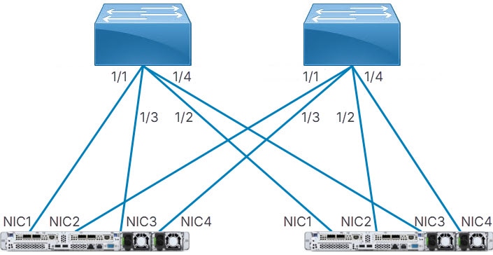
If your fabric includes connections between devices in the same switch group or server group, Cisco Nexus Hyperfabric allocates ports to device pairs in different groups first, then allocates ports to devices in the same group.
Add a root certificate for secure Transport Layer Security connectivity
You can configure switches to trust root certificates issued by their organization for establishing a secure Transport Layer Security (TLS) connection to Cisco Nexus Hyperfabric.
Follow these steps to add a root certificate for secure Transport Layer Security connectivity.
Step 1 | Choose . 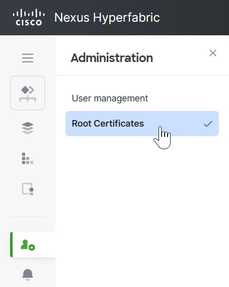
|
Step 2 | Select + Add Certificate. 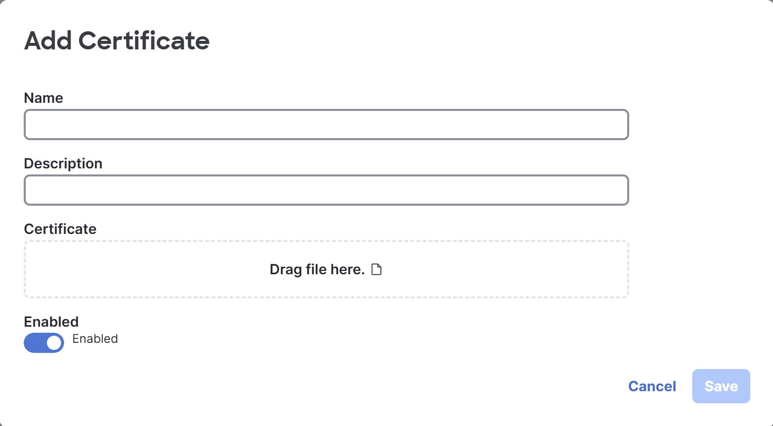
|
Step 3 | Fill out the fields, then select Save. For Certificate, drag the file with the certificate to the box, or select the box, navigate to the file, select the file, and select Open. |
Configuring switch ports
Configure a port at the switch level
You can configure various properties of a switch's port, such as the role and speed, and breakout status. The port role specifies the type of connection provided by a port.
Follow these steps to configure a port at the switch level.
Step 1 | Choose Fabrics, then select the fabric that contains the switch. |
Step 2 | If the fabric is not in the edit mode, select Switch to edit mode. |
Step 3 | In the Topology area, select the switch you want to configure, then select the switch name. |
Step 4 | In the Configure area, select Port configurations. The Port configurations table lists all ports of the switch. 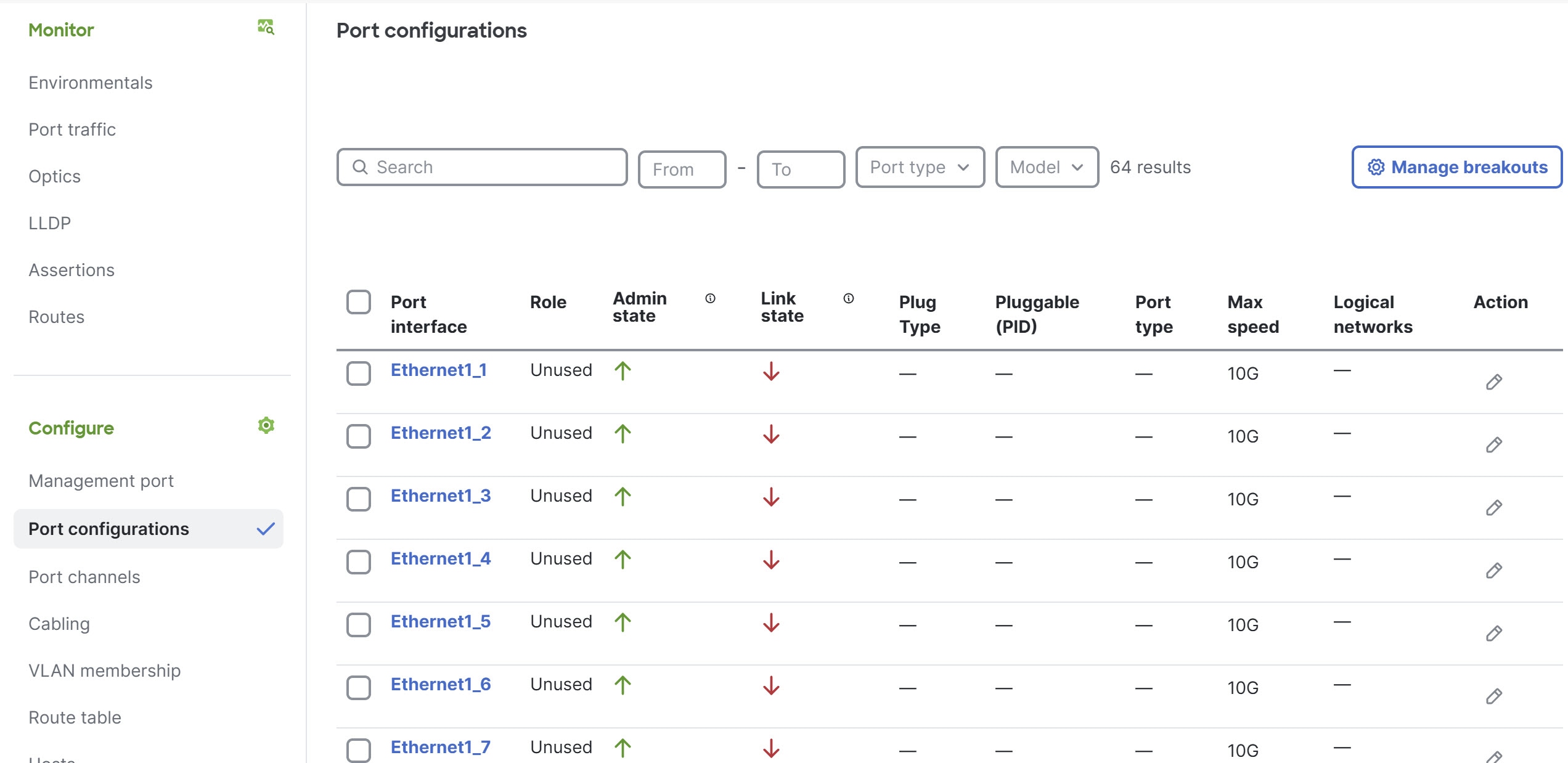
|
Step 5 | (Optional) If you want to enable or disable breakout for any of the ports, select Manage breakouts.
|
Step 6 | In the Port configurations table, under the Action column, select edit ( A dialog box opens for configuring the port. 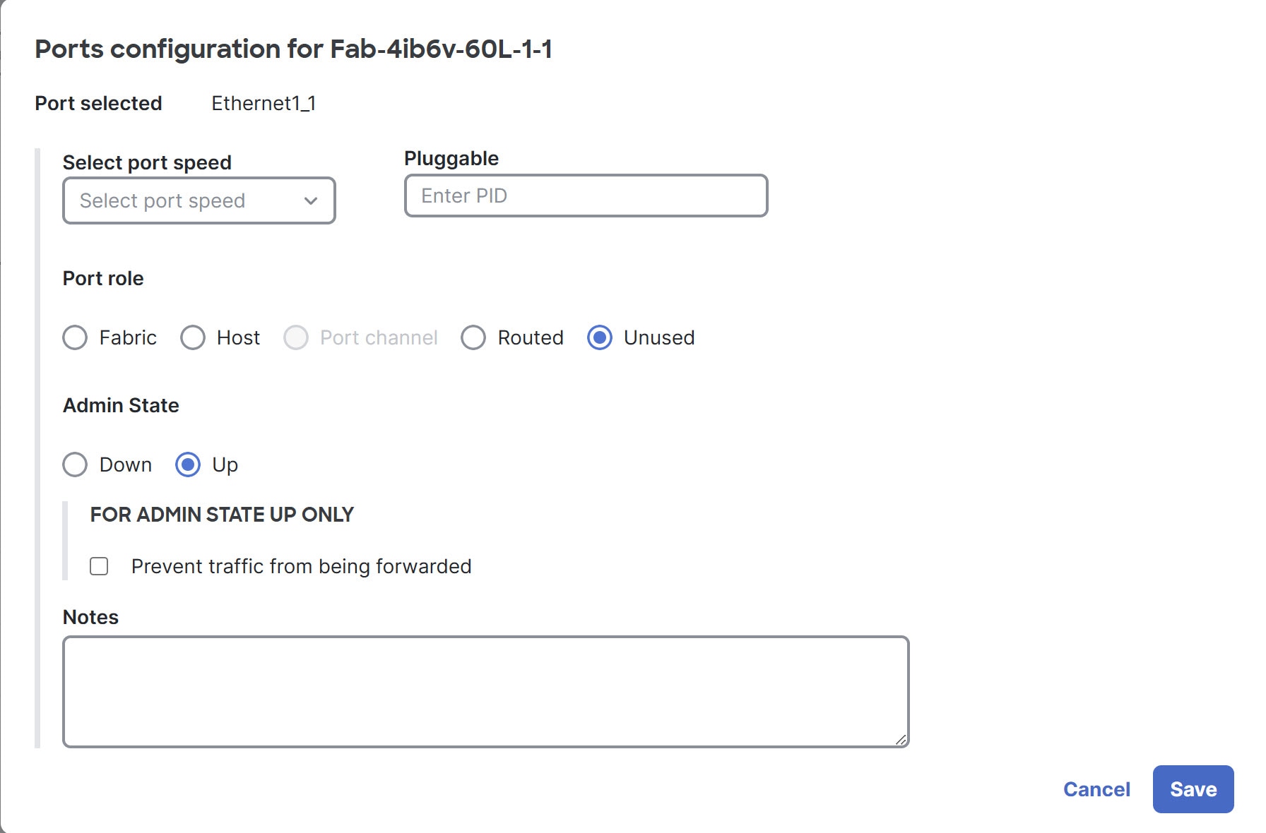
|
Step 7 | Repeat the previous step for every port on this switch that will connect to another leaf or spine switch or host in the fabric. |
Step 8 | Repeat this procedure for every leaf or spine switch in the fabric. |
Configure multiple ports at the switch level
You can configure various properties of multiple ports of a switch simultaneously, such as the role and speed. The port role specifies the type of connection provided by a port.
Some property choices reveal additional properties that you cannot set with this procedure. To configure these additional properties, you must configure the ports individually. The descriptions in each step indicate which properties have this limitation.
Follow these steps to configure multiple ports at the switch level.
Step 1 | Choose Fabrics, then select the fabric that contains the switch. |
Step 2 | If the fabric is not in the edit mode, select Switch to edit mode. |
Step 3 | In the Topology area, select the switch you want to configure, then select the switch name. |
Step 4 | In the Configure area, select Port configurations, then select the ports that you want to configure by putting a check in the box next to each port ID. 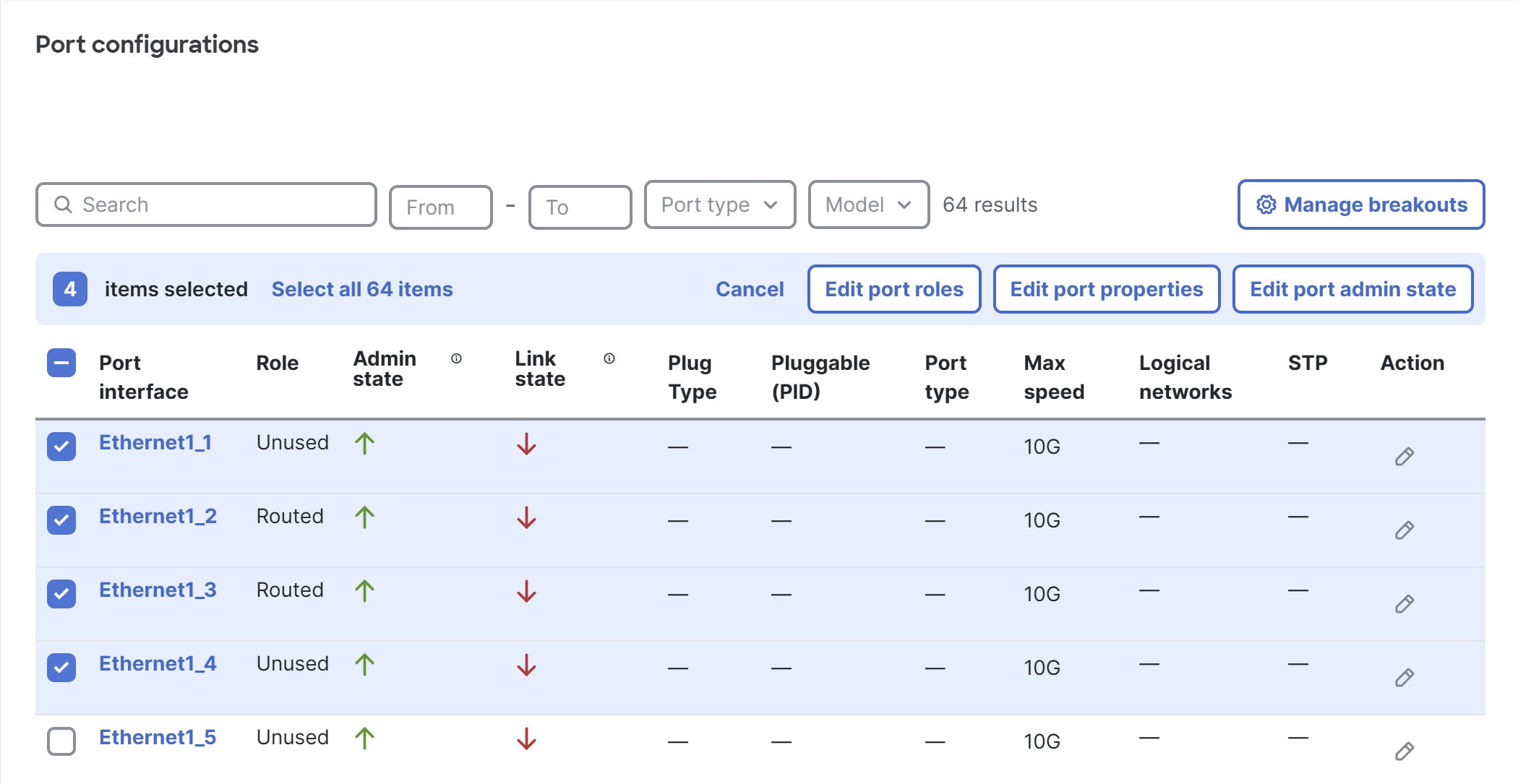
|
Step 5 | To change the role of the ports, select Edit port roles.
|
Step 6 | To change port properties, select Edit port properties. These properties include port speed and pluggable options.
|
Step 7 | To change the administrative state, select Edit port admin state.
|
Configure a switch port at the fabric level
You can configure any port of any switch in a fabric by going to the Physical topology area of that fabric. This page makes it easy to configure the ports of different switches.
Follow these steps to configure a port at the fabric level.
Step 1 | Choose Fabrics, then select the fabric that contains the switch for which you want to configure its ports. |
Step 2 | If the fabric is not in the edit mode, select Switch to edit mode. |
Step 3 | In the Physical topology area, select Port configurations. The Port configurations table lists all ports of all switches in the fabric. |
Step 4 | Above the Port configurations table, you can use the various fields and drop-down lists to filter the table.
|
Step 5 | In the Action column, select edit (
|
Configure multiple switch ports at the fabric level
You can configure any switch port in a fabric by going to the Physical topology area of that fabric. This page makes it easy to configure the ports of multiple switches simultaneously.
Some property choices reveal additional properties that you cannot set with this procedure. To configure these additional properties, you must configure the ports individually. The descriptions in each step indicate which properties have this limitation.
Follow these steps to configure multiple ports at the fabric level.
Step 1 | Choose Fabrics, then select the fabric that contains the switches for which you want to configure their ports. |
Step 2 | If the fabric is not in the edit mode, select Switch to edit mode. |
Step 3 | In Physical topology, select Port configurations. The Port configurations table lists all ports of all switches in the fabric. |
Step 4 | Above the Port configurations table, you can use the various fields and drop-down lists to filter the table.
|
Step 5 | Select the ports that you want to configure by checking the box next to each port ID. The ports can belong to different switches. |
Step 6 | To change the role of the ports, select Edit port roles.
|
Step 7 | To change the port properties, select Edit port properties. The properties include the port speed and pluggable.
|
Step 8 | If you want to change the admininistrative state, select Edit port admin state.
|
Guidelines for configuring ports
With the Cisco HF6100-60L4D switch, when you configure the speed of one of the SFP56 ports in a port group, the speed of the other port gets configured with the same speed.
Finish and commit the design
Your changes are not applied to the fabric until you review, commit, and push them.
Follow these steps to finish and commit the design.
Step 1 | Select Review configuration. |
Step 2 | Verify your changes in the review list. |
Step 3 | Select Comment and push. |
Step 4 | In the Comment before pushing configuration dialog box, enter the reason for the change. |
Step 5 | Select Push configuration. If you bound any devices as part of this push, the outline color of the device icons indicates the assertions for the devices. The devices should have a green outline, which indicates that there are no issues. A yellow outline indicates the device has an unexpected condition and there are issues detected, but the issues should not cause operation disruption. A red outline indicates the device has an unexpected condition and there are issues detected that can cause operation disruption; you should investigate the issues. 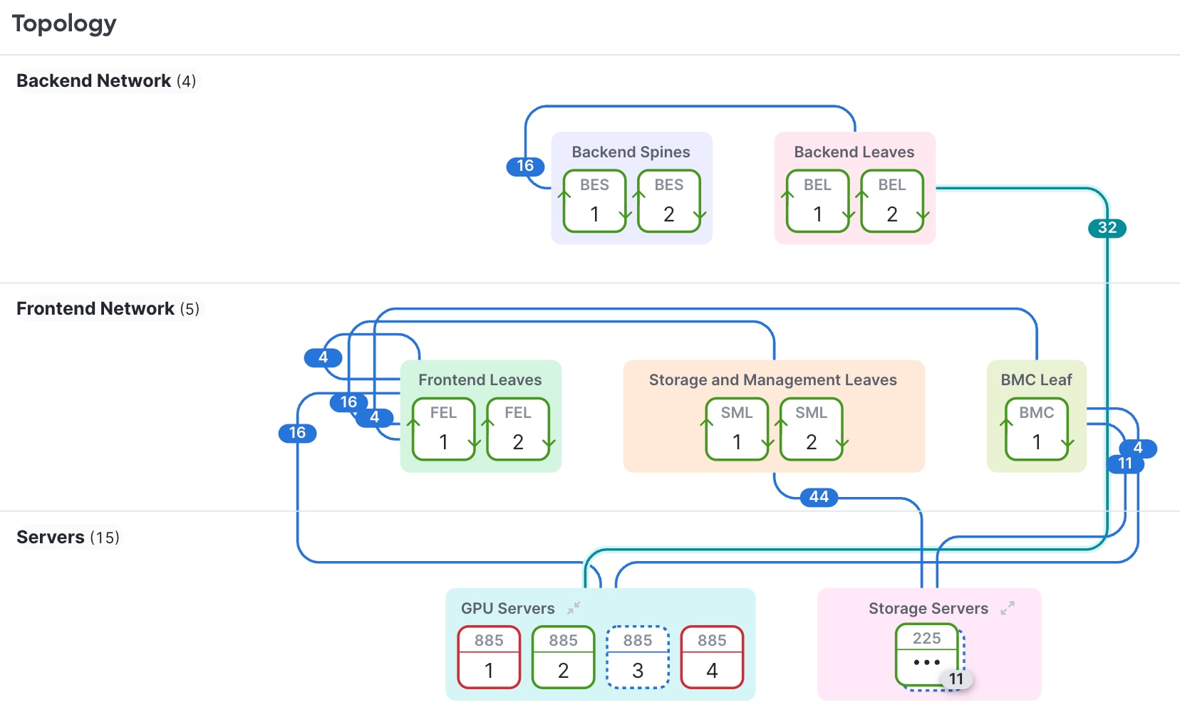
|
Bill of materials and ordering
Deployment
Deployment provides information about the assembly list and bill of materials (BOM) calculations and specifies if you need any parts for your fabric. You can export a CSV file of the assembly list and BOM for reference outside of Cisco Nexus Hyperfabric.
View or export deployment information
You can view deployment information or also export the deployment information to a CSV file to use as reference. You can view or export this information:
- A bill of materials for ordering products to build the fabric according to the blueprint design
- An assembly list to check the fulfillment of the necessary accessories, such as fans, power supplies, and optics required for each device
Follow these steps to view or export deployment information.
Step 1 | Choose Fabrics, then select the desired fabric. |
Step 2 | Select . 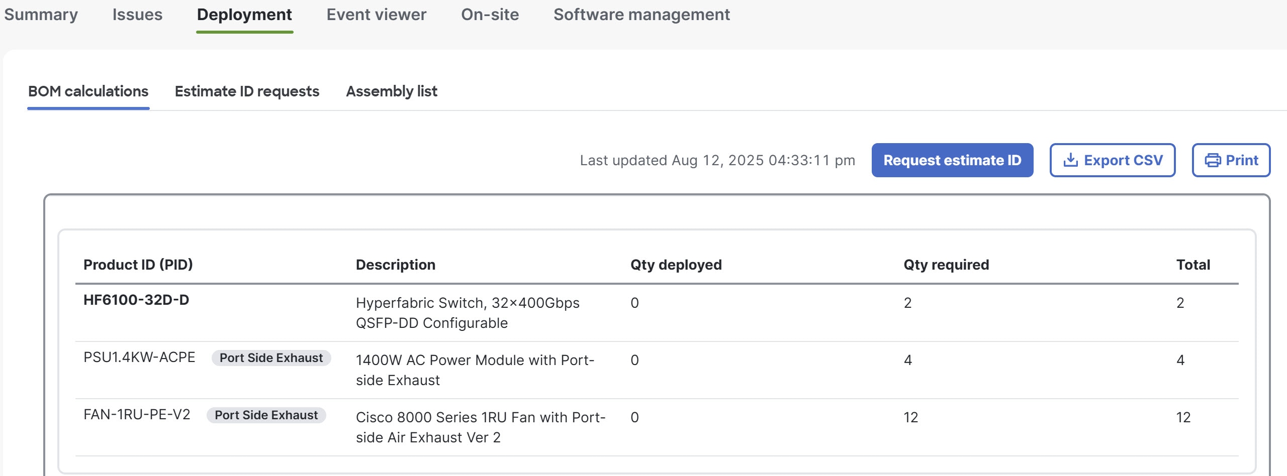
This page displays a bill of materials (BOM) of product IDs (PIDs), which specify the devices and accessories needed for this fabric design, as well as the optics based on the port connection configuration. The table shows how many of each PID are required and how many have been received and deployed. |
Step 3 | (Optional) To export the BOM as a comma-separated value (CSV) spreadsheet, select Export CSV. |
Step 4 | Select the Assembly list. 
This page displays a list of accessories, such as fans, power supplies, and optics required for each device. The table indicates whether the parts have been deployed and, if available, the serial numbers of the deployed parts. |
Step 5 | (Optional) To export the assembly list as a comma-separated value (CSV) spreadsheet, select Export CSV. |
Request an estimate ID for a bill of materials
When you request an estimate ID for a bill of materials (BOM), Cisco Nexus Hyperfabric communicates with the Cisco Commerce Workspace (CCW) to create the estimate and sends you an email with the estimate ID. You can then work with your partner or sales team contacts to discuss the estimate and order the parts.
Cisco Nexus Hyperfabric retains estimate IDs for 90 days. From the Estimate ID requests page, you can download any of the BOMs to save for a longer amount of time. If an estimate ID expires, you can request a new estimate ID.
Follow these steps to request an estimate ID for a bill of materials.
Step 1 | Choose Fabrics. |
Step 2 | Select the fabric that has the BOM for which you want the estimate ID. |
Step 3 | Select . |
Step 4 | Select Request estimate ID and perform these substeps.
|
Step 5 | Provide your Cisco partner or sales team contacts with the estimate ID. The estimate created by Cisco Nexus Hyperfabric is read-only. Your contacts must create a clone of the estimate, which will have a new estimate ID. Your contacts will then assist you with the cost estimate and complete your order using the new ID. |
Onboarding the fabric
Onboard a fabric
This procedure provides a high-level overview of the tasks you must perform to onboard a fabric.
Before you can onboard a fabric, you must physically install your fabric and wire the fabric to match the Cisco Nexus Hyperfabric blueprint.
Follow these steps to onboard a fabric.
Step 1 | Allow the switches to contact the Cisco Nexus Hyperfabric cloud service. |
Step 2 | Claim the switches to your organization. For more information, see Claiming devices. |
Step 3 | Bind each switch to its position in your fabric blueprint, allowing it to receive its specific configuration from the Cisco Nexus Hyperfabric. For more information, see Bind the devices. |
Step 4 | If you are deploying AI clusters, follow these substeps.
|
Prerequisites for onboarding
Before you can onboard your installed fabric, you must have the following:
- A working Internet connection to which a switch can connect for HTTPS (port 443) traffic
- An available DNS server
- A configured proxy server, if needed to reach the cloud
-
At least one management IPv4 or IPv6 address for a switch in your fabric
Note
We recommend that you connect all switches in your fabric to a management network.
Connect the first switch to the Cisco Nexus Hyperfabric cloud service
Upon delivery, a new Nexus Hyperfabric switch contains an agent that allows it to discover its neighbors and to contact Cisco Nexus Hyperfabric.
The following diagram shows an example of configuring the first switch for out-of-band (OOB) management node connection to the Cisco Nexus Hyperfabric. The management node configuration can be achieved through DHCP, if available, or by serial port configuration if you need a static IP address.
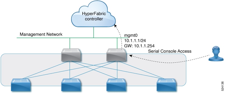
Typically, you will need to connect physically only one switch to the cloud. This switch automatically contacts Cisco Nexus Hyperfabric. When discovered by its neighbor switches in the fabric, this switch reports its availability as the "exit node" switch. Neighboring switches that lack OOB management connectivity can connect to Cisco Nexus Hyperfabric through the exit node switch.
Follow these steps to connect the first switch to the Cisco Nexus Hyperfabric cloud service.
Step 1 | At the physical site, select a switch that will have the initial Internet connection. This cloud-connected switch will become the exit node. |
Step 2 | Connect the switch's OOB management interface to an Internet connection. |
Step 3 | If a DHCP server is present, you can skip the remaining steps in this procedure. The switch will receive its DHCP configuration and will then contact Cisco Nexus Hyperfabric through the Internet connection. |
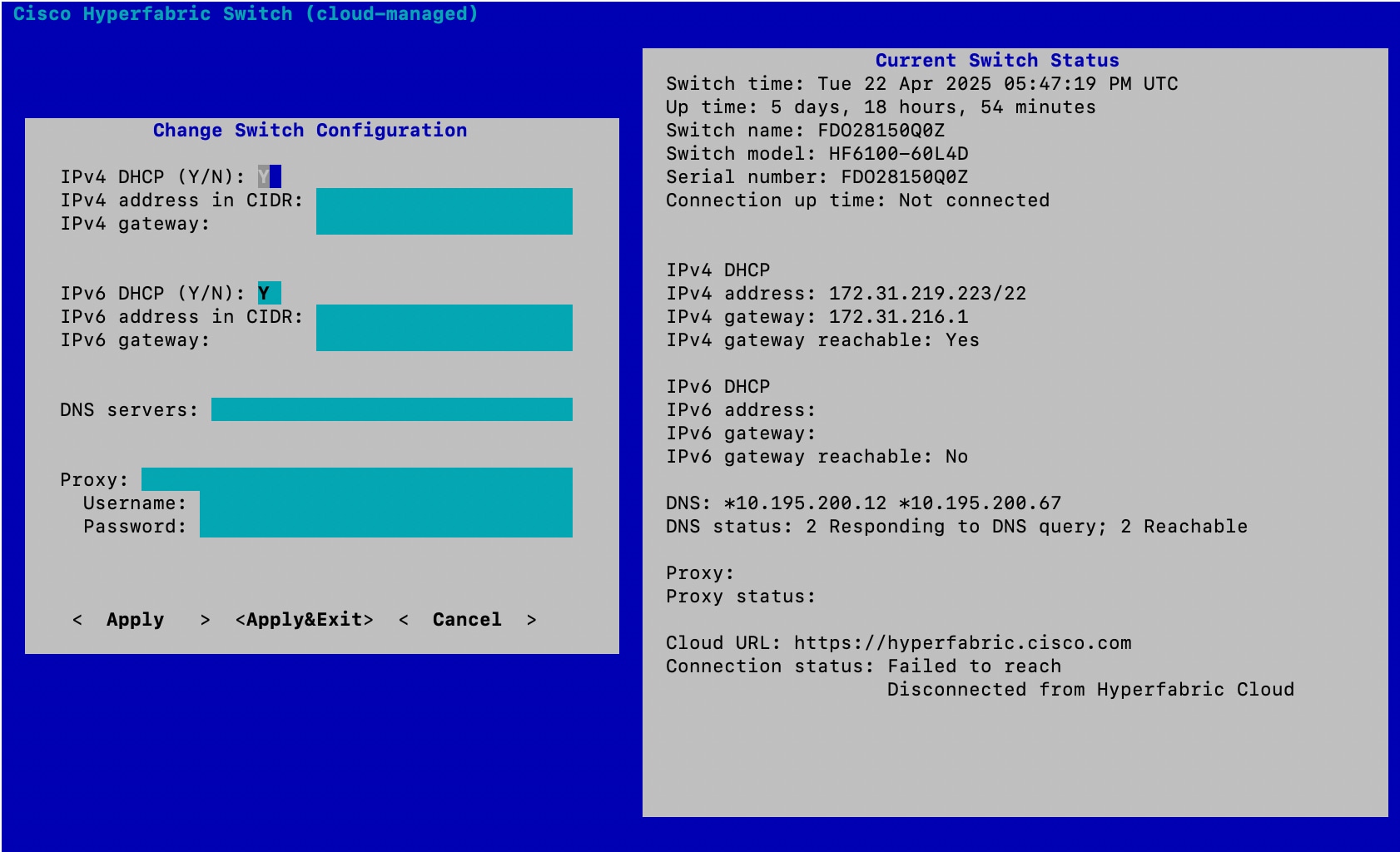
Step 4 | If you must configure a static IP address or if you must configure a proxy, connect a terminal to the serial console port of the switch using these connection parameters:
|
Step 5 | Log in to the serial console using "ttg-admin" as the username and "hfabric2025" as the password. You are asked whether you want to change the default password, which we recommend that you do.
|
Step 6 | In the console menu, select Change Configuration. 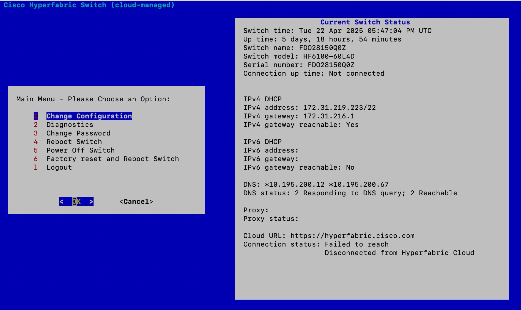
|
Step 7 | Select Apply.
|
 Tip
TipPreparing servers
Install the Cisco Nexus Hyperfabric agent on a server
You must install the Cisco Nexus Hyperfabric agent on a server to enable Nexus Hyperfabric to control the server.
Follow these steps to install the Cisco Nexus Hyperfabric agent on a server.
Step 1 | Use SSH to connect to the server. |
Step 2 | Configure the NVIDIA BlueField-3 (BF3) data processing unit to use the NIC mode.
|
Step 3 | Power cycle the server.
|
Step 4 | Install the Nexus Hyperfabric agent on the server.
|
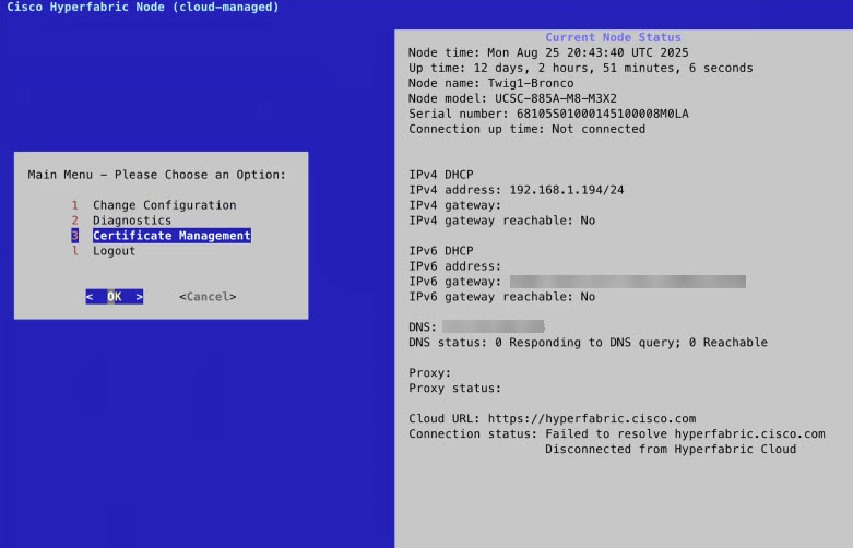
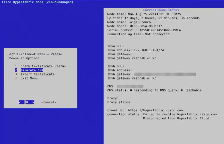
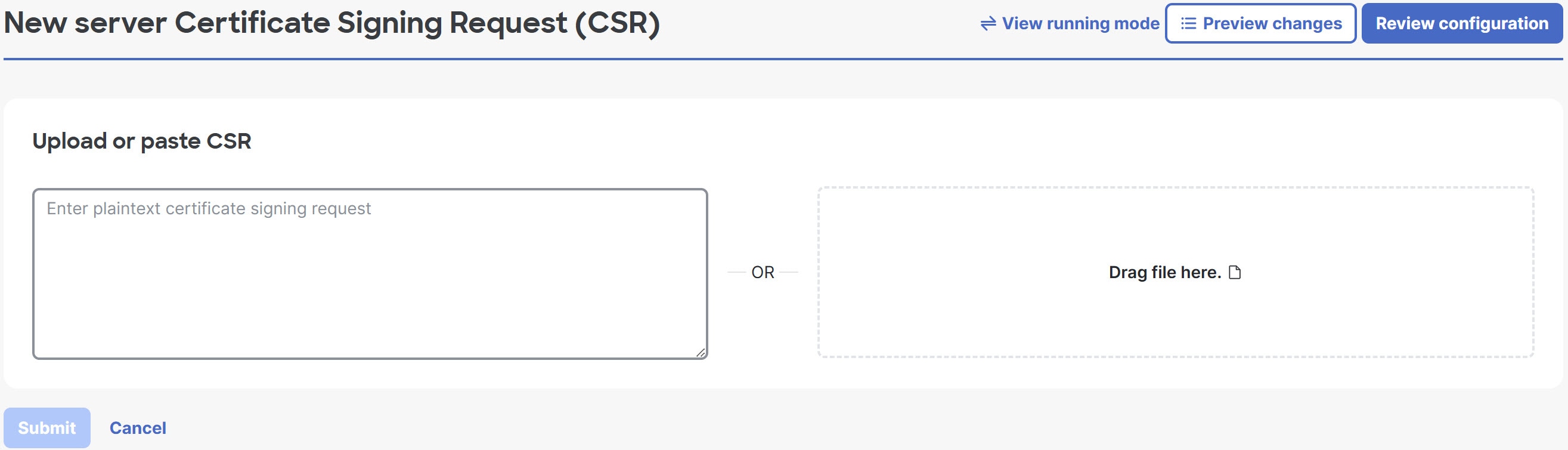
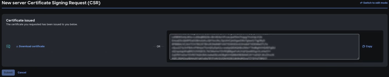
Step 5 | Generate a certificate signing request (CSR), use the CSR to get a certificate, and import the certificate in the server. You can use an automated process or a manual process for these actions. This step provides both processes in separate substeps. To use the automated process for these actions, follow these substeps:
To use the manual process for these actions, follow these substeps:
|
Considerations for installing the Cisco Nexus Hyperfabric agent
These considerations apply for installing the Cisco Nexus Hyperfabric agent:
- You can install the agent on a server only after you have installed OpenShift CoreOS as the host operating system on that server.
- Connect a server on which you installed the Nexus Hyperfabric agent to the Nexus Hyperfabric cloud controller for configuration management and telemetry. The agent can use any port, depending on the server routing table that is available in its kernel, regardless of how ports are used. For example, the ports can be used for east-west traffic, north-south traffic, and management. If the communication must be through management interfaces, you must configure a routing table accordingly. If the agent cannot reach the cloud controller directly, the agent relies on an exit node in the fabric to reach the controller.
Cisco Nexus Hyperfabric server agents and ISO images
This table provides the download location of the agents and ISO images that you need to use servers with Cisco Nexus Hyperfabric.
|
Agent or ISO image |
Download location |
|---|---|
|
UCS agent installer |
Download the appropriate package. RPM: https://cdn.hyperfabric.cisco.com/server/releases/agent/latest/ucs_agent_installer_latest.rpm DEB: https://cdn.hyperfabric.cisco.com/server/releases/agent/latest/ucs_agent_installer_latest.deb |
|
Nexus Hyperfabric deployment agent For installation information, see Install the Cisco Nexus Hyperfabric agent on a server. |
https://cdn.hyperfabric.cisco.com/server/releases/agent/latest/hf_agent_deploy.yaml |
Claiming devices
Upon delivery, a new device is not associated with any owner or organization. Before deploying the device, you must claim it through Cisco Nexus Hyperfabric and add it to the organization that owns the fabric in which the device will be deployed.
NoteIn some cases, your devices might already be claimed for your organization before delivery. If so, you can skip the claim procedures.
To claim the device, you must have physical and administrative access to the device.
Limitations for claiming devices
These limitations apply for claiming devices:
- You must claim the first device of your fabric using a claim code.
- When claiming devices without using claim codes, you can claim only switches that Cisco Nexus Hyperfabric has discovered. The discovery process is limited to switches that are directly connected to an already-claimed Nexus Hyperfabric switch. Only these directly connected devices will appear in the discovered list and be available for claiming.
Claim a switch using a claim code
You must claim the first switch of your fabric using a claim code. You can also claim subsequent switches using claim codes or you can claim discovered switches without using the claim codes. For information about claiming a switch without using a claim code, see Claim a discovered device without using a claim code.
Follow these steps to claim a switch using a claim code.
Step 1 | Use the serial console to log in to the switch and get the claim code that is shown in the serial console menu. If you want to claim multiple switches, then get the code from every switch that you want to claim. The claim code that displays in the console changes every two minutes, although a code is valid for four minutes. 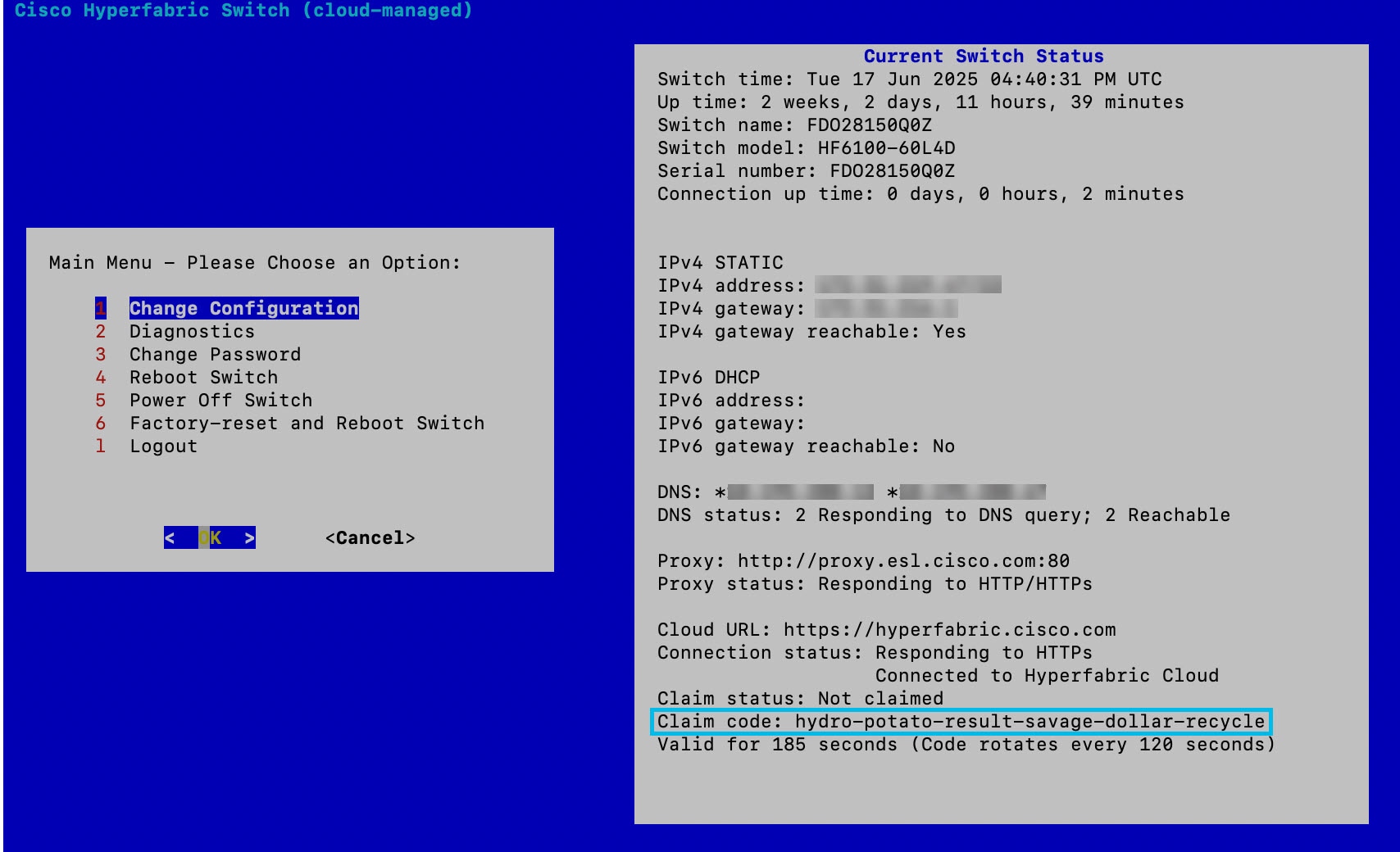
|
Step 2 | In the Cisco Nexus Hyperfabric GUI, choose . |
Step 3 | Select Claim devices. |
Step 4 | Enter the claim code, then select Claim. If you want to claim multiple switches, enter the codes separated by commas or new lines. The switch then becomes registered to the current organization as claimed. As the other fabric switches are installed and connected, unclaimed switches connected to the first switch will be discovered. |
Claim a discovered device without using a claim code
You must claim the first device of your fabric using a claim code, which means you cannot use this procedure for the first device. However, you can claim additional discovered devices without using the claim codes. For information about claiming the first device or a subsequent device using a claim code, see Claim a switch using a claim code.
You cannot use a baseboard management controller (BMC) port to claim a server.
Follow these steps to claim a discovered device without using a claim code.
Step 1 | Select . |
Step 2 | Click Claim devices. |
Step 3 | Click Claim discovered devices. 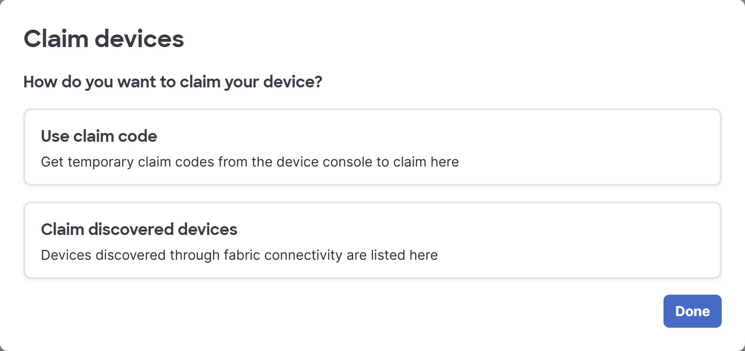
|
Step 4 | Select one or more switches, then click Claim. 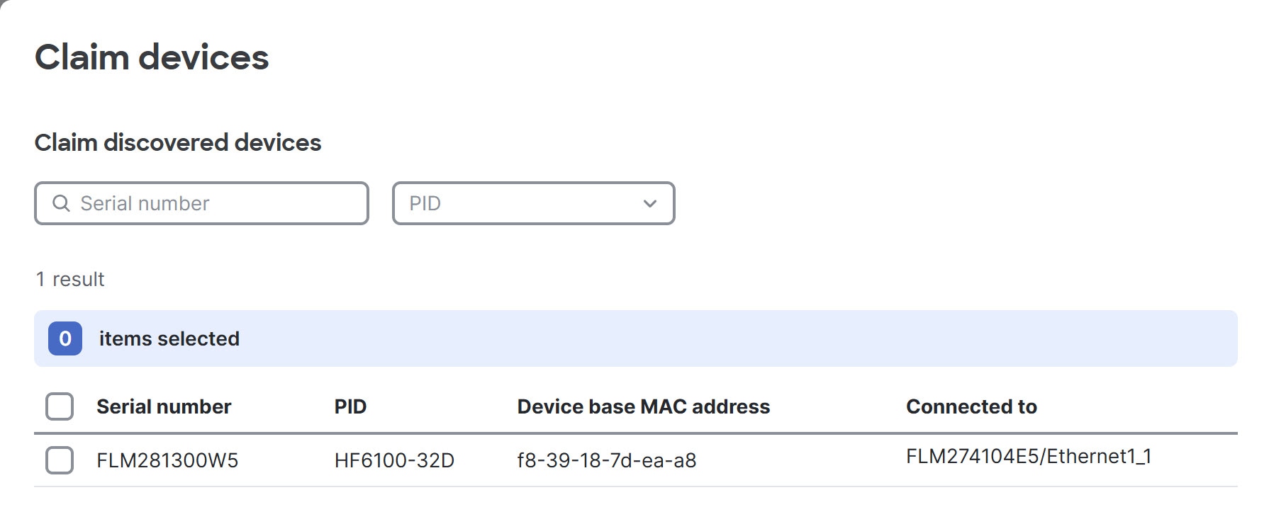
The devices then become registered to the current organization as claimed. Optionally, you can find the device with a specific serial number using the Serial number field and filter for switches with the product ID that you select from the PID drop-down. |
Bind the devices
In Cisco Nexus Hyperfabric, you must assign each physical device ("bind") to its logical position (node) in the fabric blueprint. When a device has been bound to a node in the blueprint, it can download its configuration from Cisco Nexus Hyperfabric.
A device that has been claimed but not yet bound to an organization's fabric is considered to be bound to the parking lot—a "null" fabric—until it is bound to an actual fabric.
Follow these steps to bind the devices.
Step 1 | Choose Fabrics. |
Step 2 | Select the fabric that contains the devices. |
Step 3 | If the fabric is not in the edit mode, select Switch to edit mode. |
Step 4 | In the Topology area, select the position of the device that you want to bind, then select Bind in the device information pane. 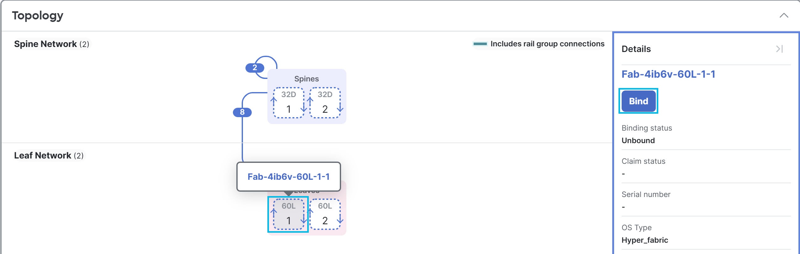
If a group has more than two devices, you must expand the group before you can select the position. 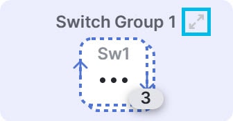
|
Step 5 | Select the physical device to assign to this position in the topology. The resulting dialog displays two options for the device configuration. 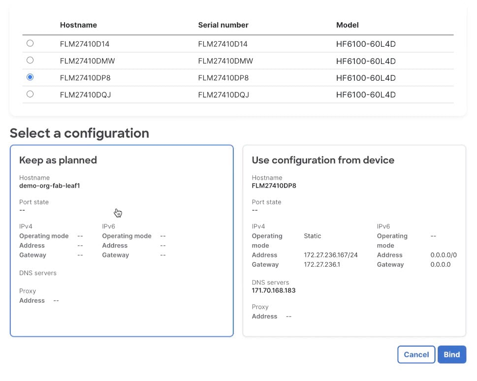
|
Step 6 | Select the configuration.
|
Step 7 | To bind the device to this logical location in the fabric blueprint, select Bind. When the binding operation for a device has completed successfully, the device icon in the topology view is blue. |
Step 8 | Repeat these steps to bind the remaining devices. |
Step 9 | Verify the cloud connectivity status of the devices.
|
View switch details by scanning the QR code
The Cisco 6000 series switches have stickers that have a unique QR code. The QR code provides a launch URL that contains the serial number of the switch. You can use a mobile device to scan the code, then open the URL to go to the switch details page in the Cisco Nexus Hyperfabric GUI.
For more information about the QR code, see the Cisco Nexus Hyperfabric Series – QR Code document.
Follow these steps to view switch details by scanning the QR code.
Step 1 | Use a mobile device to scan the QR code. |
Step 2 | Go to the URL that the code provides. One of these results occurs:
|
Finish and commit the design
Your changes are not applied to the fabric until you review, commit, and push them.
Follow these steps to finish and commit the design.
Step 1 | Select Review configuration. |
Step 2 | Verify your changes in the review list. |
Step 3 | Select Comment and push. |
Step 4 | In the Comment before pushing configuration dialog box, enter the reason for the change. |
Step 5 | Select Push configuration. If you bound any devices as part of this push, the outline color of the device icons indicates the assertions for the devices. The devices should have a green outline, which indicates that there are no issues. A yellow outline indicates the device has an unexpected condition and there are issues detected, but the issues should not cause operation disruption. A red outline indicates the device has an unexpected condition and there are issues detected that can cause operation disruption; you should investigate the issues.
|