
Cisco Nexus Hyperfabric — Configure Fabrics
Fabrics
A fabric is a collection of devices specific to one organization, and each device is specific to a single fabric. A fabric is the configuration and monitoring domain; users configure fabrics, not individual devices. A fabric is also a blueprint to which physical devices are bound and interconnected. The blueprint helps ensure the adherence to all physical and logical designs.
These are some of the things that you define in a fabric blueprint:
- Device model
- Number of spine switches, leaf switches, and servers
- Through which port the devices are connected
- VRF instance, VNI, and VLAN configuration
- Routing configuration
- Target software release for the devices in the fabric
Designing the fabric blueprint
When you have created a new organization or need to add a fabric to an existing organization, you can use the Blueprint Designer in the Cisco Nexus Hyperfabric to create a blueprint for the new fabric.
Create a fabric without using a template
Follow these steps to create a fabric without using a template.
Step 1 | Choose Fabrics. |
Step 2 | Select + Add new fabric and select New fabric.
|
Step 3 | Follow these substeps to configure the switch tiers.
To design a single-switch fabric or a mesh fabric with a switch model, create only one switch group. If you need to add another switch model, add another switch group. For example, you can have two switch groups—one for spine switches and one for leaf switches—to create a spine and leaf topology. As you make your switch choices, Cisco Nexus Hyperfabric updates the topology. |
Step 4 | In the Switch groups area of Group connections, select a box to configure the connections between the corresponding switch groups. The connections between the switch groups are displayed in a matrix of boxes. The matrix defines how the switches are connected to one another. The top and side labels show the names of the switch groups; the labels match on both axes. Each box shows the number of connections per switch group pair and is labelled with a letter such as A, B, or C. The Connections property specifies the number of connections, which you can change as indicated in the substeps. Each letter indicates a unique pair of switch PIDs, which can help you to identify outliers or misconfigurations quickly. The switches of the switch group specified by the left label are connected under the switches of the switch group indicated by the top label. The exception is if the switch group is the same on both axes, in which case the switches of that group are interconnected. As an example, assume you have two switches in a switch group named "Spine", four switches in another switch group named "Leaf", and you specify "2" for Connections between the groups. This means you have eight pairs of switches. Because you specified two connections, you have 16 total connections between the groups. After you select a box, the right side of the Switch groups area shows the properties of the group connections. You can select multiple boxes to see each of those group connections at the same time. For a selected switch group's connections, perform these substeps.
|
Step 5 | If your fabric will contain servers, follow these substeps.
|
Step 6 | Select Save fabric blueprint. The Saving fabric blueprint dialog appears and informs you that Cisco Nexus Hyperfabric generated the blueprint. |
Step 7 | If you want Cisco Nexus Hyperfabric to create the cabling plan now, select Run cabling. Otherwise, select Continue to topology. |
 ) next to the default name, modify the name, and select
 Create a fabric using a template
You can create a fabric using a template, which has a predefined topology. You select a template based on the size of the fabric that you want to create.
Follow these steps to create a fabric using a template.
Step 1 | Choose Fabrics. |
Step 2 | Select + Add new fabric and select New from template. |
Step 3 | On the Templates page, select AI clusters or Switch fabrics as appropriate. |
Step 4 | Select the template with the topology that you want. |
Step 5 | If you want to change the default fabric name, select edit ( |
Step 6 | Modify the topology as appropriate, then select Save fabric blueprint. |
Modifying fabrics
If you have administrator or read-write access to the organization, you can modify the design of an existing fabric on the Fabrics page. You can make changes to the fabric blueprint at any stage: from an undeployed fabric design to an installed and running fabric.
The Fabrics blueprint page operates in one of two modes:
- Edit mode: This is the default mode for a user with administrator or read-write access. All fabric edit options are exposed.
- Running mode: This is the default mode for a user with read-only access. Settings and status are displayed, but no edit options are exposed. You can switch to edit mode only if you have administrator or read-write access.
All configuration procedures in this document assume that you are logged in with administrator or read-write access, and that the menus are in edit mode.
Modify a fabric
This procedure provides the typical workflow for making fabric configuration changes.
Follow these steps to modify a fabric.
Step 1 | Choose Fabrics, then click the fabric that you want to configure. |
Step 2 | If the fabric is not in the edit mode, click Switch to edit mode. |
Step 3 | Make your changes.  Note NoteYour changes are not applied to the fabric until you review, commit, and push them. |
Step 4 | When you're ready to apply your changes, click Review configuration. 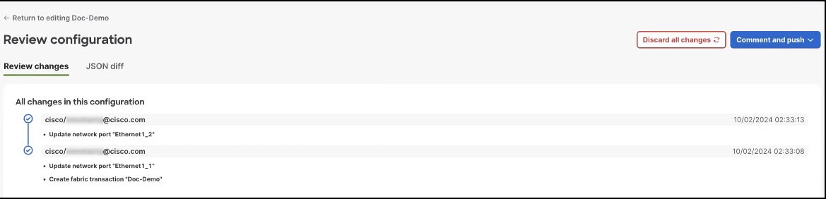
In the Review configuration page, you can view a list of brief descriptions of the changes since the last push, including the author's ID and the date and time when the change was saved. |
Step 5 | When you have reviewed the changes and are ready to apply them, click Comment and push. |
Step 6 | In the Comment before pushing configuration dialog box, enter the reason for the change. |
Step 7 | Click Push configuration. |
Step 8 | View the status of your changes. On the Fabrics blueprint page, view the fabric card to see the status of the pushed changes. Your changes may take some time to apply or they might generate red assertions. For example, if you push changes to an installed and running fabric, and the changes conflict with the physical cabling of the fabric, an assertion is raised. |
Cabling
Cisco Nexus Hyperfabric automatically determines how you should cable the devices in a fabric based on the number of connections per device pair and cabling strategy. The cabling strategy comprises two notions.
The first notion comprises these things:
- Strict: Cisco Nexus Hyperfabric connects each device pair with the number of connections that you selected. If a device does not have enough available ports for any reason, Cisco Nexus Hyperfabric indicates that there is an error with the cabling.
- Best effort: Cisco Nexus Hyperfabric connects each device pair with the number of connections that you selected if possible. However, if a device does not have enough available ports for any reason, Cisco Nexus Hyperfabric connects the devices in the pair to other devices in the same switch group that have enough available ports.
The second notion comprises these things:
-
Dense: Cisco Nexus Hyperfabric connects consecutive ports of a device to consecutive ports of a paired device. The number of consecutive ports is equal to the number of connections per device pair that you selected. Cisco Nexus Hyperfabric repeats this connecting of consecutive ports for each successive paired device. This is used for switch-to-switch connections.
Switch-to-switch dense cabling strategy with two spine switches and two leaf switches 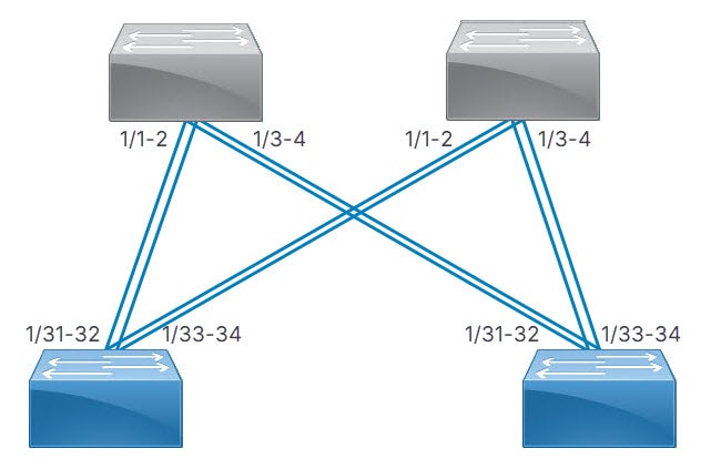
-
Distributed: Cisco Nexus Hyperfabric connects the first network interface card (NIC) of the first server to the first port of the first switch, then the second NIC of the server to the first port of the second switch, and so on until the server has one connection to the first port of each switch. Cisco Nexus Hyperfabric repeats this process with the successive servers, but the NICs connect to the successive port of each switch. After each servers' NICs are connected to each switch, the entire process repeats until there are a number of connections from each server to each switch equal to the specified number of connections.
Server port groups that have GPUs also use the distributed cabling strategy. In the rail group properties, these servers have width equal to the number of GPU servers and a count of 8.
With or without GPUs, the same NIC number on each server connects to the same switch. Thus, for a fabric with two servers (server1 and server2) and two switches (switch1 and switch2), NIC1 of both servers connect to switch1 while NIC2 of both servers connect to switch2.
Switch-to-server distributed cabling strategy with two leaf switches and two servers 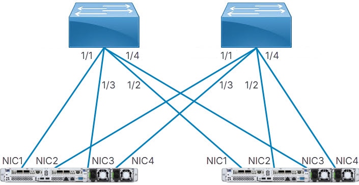
If your fabric includes connections between devices in the same switch group or server group, Cisco Nexus Hyperfabric allocates ports to device pairs in different groups first, then allocates ports to devices in the same group.
Modify a fabric topology
To add or remove switches, or to otherwise modify the topology of an existing fabric, navigate to the Fabrics page. In this menu, you can define the blueprint for the fabric. See the terminology section in the Cisco Nexus Hyperfabric Getting Started document. When you modify the fabric, the Nexus Hyperfabric creates a new blueprint.
Follow these steps to modify a fabric topology.
Step 1 | Select Fabrics, then select the fabric that you want to modify. |
Step 2 | If the fabric is not in the edit mode, select Switch to edit mode. |
Step 3 | In the Topology area, select Edit fabric. |
Step 4 | In the Edit fabric dialog box, set the properties as desired.
|
Step 5 | Select Save. |
Considerations for modifying a fabric topology
Removing a switch or a cable from a fabric topology impacts traffic going through the interface that you removed from the fabric. Adding a switch or a cable does not impact traffic.
Finish and commit the design
Your changes are not applied to the fabric until you review, commit, and push them.
Follow these steps to finish and commit the design.
Step 1 | Select Review configuration. |
Step 2 | Verify your changes in the review list. |
Step 3 | Select Comment and push. |
Step 4 | In the Comment before pushing configuration dialog box, enter the reason for the change. |
Step 5 | Select Push configuration. If you bound any devices as part of this push, the outline color of the device icons indicates the assertions for the devices. The devices should have a green outline, which indicates that there are no issues. A yellow outline indicates the device has an unexpected condition and there are issues detected, but the issues should not cause operation disruption. A red outline indicates the device has an unexpected condition and there are issues detected that can cause operation disruption; you should investigate the issues. 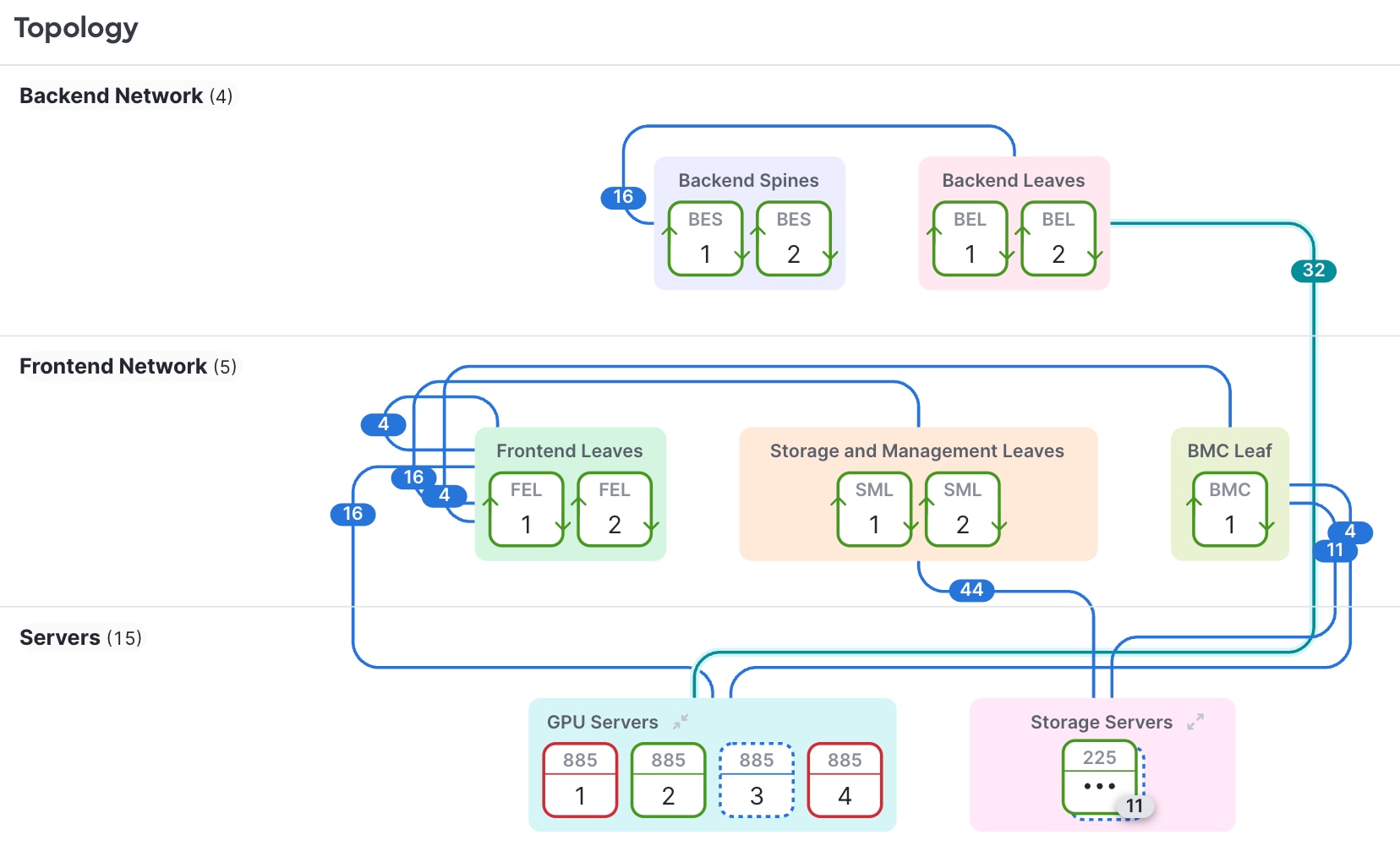
|
Exporting and importing a fabric blueprint
Export a fabric blueprint
You can export a fabric blueprint, which Cisco Nexus Hyperfabric saves as a JSON file on your local system. One use case of exporting a blueprint is that you can then import that blueprint into another organization to create the same fabric in that organization.
Follow these steps to export a fabric blueprint.
Step 1 | Choose Fabrics. |
Step 2 | For the fabric whose blueprint you want to export, select . Cisco Nexus Hyperfabric saves a JSON file of the blueprint on your local system. |
Import a fabric blueprint
If you have a JSON file of a fabric blueprint, you can import that blueprint into your Cisco Nexus Hyperfabric organization to create a new fabric blueprint. Cisco Nexus Hyperfabric validates the blueprint when you attempt to import it. If Cisco Nexus Hyperfabric detects issues with the blueprint, it informs you of the issues and stops the import.
Follow these steps to import a fabric blueprint.
Step 1 | Choose Fabrics. |
Step 2 | Select + Add new fabric and select Import fabric. The Import fabric configuration dialog box appears.
|
Clone a fabric blueprint
You can clone an existing fabric so that you have two identical fabric blueprints in the same organization.
Follow these steps to clone a fabric blueprint.
Step 1 | Choose Fabrics. |
Step 2 | Select ... in the tile of the fabric that you want to clone and select Clone fabric. The Clone fabric dialog box appears.
|
Considerations for exporting and importing a fabric blueprint
General considerations
The export and import functionality is not intended to be used as a save and restore functionality. For example, the JSON file of an exported fabric blueprint does not contain any password nor secrets.
Export considerations
These conderations apply for exporting a fabric blueprint:
- An exported blueprint does not contain any uncommitted configuration changes. Thus, if you made changes to the fabric but did not commit the changes, Nexus Hyperfabric will not include those changes in the exported blueprint.
- The JSON file of an exported fabric blueprint does not contain any passwords nor secrets.
Import considerations
These conderations apply for importing a fabric blueprint:
- An imported fabric blueprint does not have any bound switches. You must bind switches after importing the JSON file.
- After you import a fabric blueprint, you must manually configure any passwords and secrets that the fabric requires.
- If you want to import a fabric blueprint into an organization that already has a blueprint with the same name, you must give the imported blueprint a different name.
Fabric configuration history
Cisco Nexus Hyperfabric lets you manage fabric configurations by viewing the configuration history while you are reviewing configuration changes. From the configuration history, you can export specific revisions, restore a configuration to a prior revision, and restore a configuration from an exported revision file. You can view all past revisions, which appear by default from newest to oldest. You can filter the revisions by date range and determine who made changes and when. If you export a revision, you can choose to include secrets by providing an administrator-only password.
How restoring a fabric configuration revision works
Summary
After you select a revision to restore, whether from the Configuration history page or from a file, Cisco Nexus Hyperfabric compares the selected revision with the current configuration and performs one or more actions depending on the differences between the revisions.
Workflow
These stages describe how restoring a fabric configuration revision works.
-
Nexus Hyperfabric checks the topology by following the fabric design tree structure in this order:
- Fabric
- Tiers
- Groups
- Hardware set
- Nodes
-
Nexus Hyperfabric reconciles node-to-device bindings in this way:
When... And... Then... device A in the selected revision is bound to a node
device A in the current configuration is bound to that node
Nexus Hyperfabric makes no change.
device A in the selected revision is bound to a node
device B in the current configuration is bound to that node
Nexus Hyperfabric keeps the binding to device B and issues a warning that it changed the binding from device A to device B.
device A in the selected revision is bound to a node
no device is bound to that node in the current configuration
Nexus Hyperfabric issues an error indicating that the topology does not match.
no device is bound to a node in the selected revision
device B in the current configuration is bound to that node
Nexus Hyperfabric unbinds device B and issues a warning.
no device is bound to a node in the selected revision
no device is bound to that node in the current configuration
Nexus Hyperfabric makes no change.
-
Nexus Hyperfabric handles objects in this way:
-
Nexus Hyperfabric matches configuration objects by name. This list gives some examples of the objects:
- VRF instances
- Logical networks
- Loopbacks
- Subinterfaces
- Port channels
- Static routes
- BGP policies
- BGP peers
- DHCP relays
- Traffic classification
- IP SLA configurations
- Nexus Hyperfabric updates objects that are present in both the selected revision and the current configuration to match the selected revision.
- Nexus Hyperfabric creates objects that are only in the selected revision.
- Nexus Hyperfabric removes objects that are only in the current configuration.
-
Nexus Hyperfabric matches configuration objects by name. This list gives some examples of the objects:
Limitations for fabric configuration history
These limitations apply for fabric configuration history:
- Configuration history can display a maximum of 1,000 revisions, although there is no technical limit to the number of configurations Cisco Nexus Hyperfabric retains. Use the date range filter to narrow the display of configurations as necessary.
- If a device is unbound in the current configuration, but bound in the configuration that you selected to restore, the device will remain unbound.
- The selected configuration's topology must be a subset of or identical to the current configuration's topology. The Nexus Hyperfabric enforces this by matching the fabric design hierarchy top-down based on the position order. This means a selected configuration's entity and its matching current configuration's entity may have different names or different position numbers, but the entities must appear at the same relative rank after sorting by position. Hardware properties, such as device model, PSU model, and airflow, must match exactly at the corresponding ordinal positions. For example, if the selected configuration has tiers at positions [1, 2] and the current configuration has tiers at positions [1, 2, 3], the selected configuration's 1st tier (position 1) is matched against the current configuration's 1st tier (position 1), and the selected configuration's 2nd tier (position 2) is matched against the current configuration's 2nd tier (position 2). The current configuration's 3rd tier (position 3) has no match in the selected configuration and Nexus Hyperfabric deletes the tier upon restoring the configuration.
- You can only restore a configuration from a revision file that was exported from that same fabric.
- A Multi-Site-related configuration, such as the border port role setting on an interface and its IP address, is not included in a configuration revision. You must redo any Multi-Site-related configurations after you restore a configuration revision.
Restore a fabric configuration from a revision
You can restore a fabric configuration from the table of revisions in Configuration history. You can filter the table by time range and sort the table by any of the columns to make it easier to find a specific revision. By default, the table is in the order of newest to oldest revision.
You cannot have any uncommitted changes when you restore a revision.
Follow these steps to restore a fabric configuration from a revision.
Step 1 | Select Fabrics, then select the fabric that you want to modify. |
Step 2 | If the fabric is not in the edit mode, select Switch to edit mode. |
Step 3 | Select Review configuration, then Configuration history. |
Step 4 | (Optional) Follow these substeps to filter and sort the table to make it easier to find a revision.
|
Step 5 | In the row of the revision you want to restore, select . Nexus Hyperfabric displays a dialog with information about the revision. Follow these substeps.
|
Export a fabric configuration
You can export a fabric configuration to a revision file, which you can then use to restore that revision. You can choose to include passwords by providing a password, in which case Nexus Hyperfabric encrypts the file.
Follow these steps to export a fabric configuration.
Step 1 | Select Fabrics, then select the fabric that you want to modify. |
Step 2 | If the fabric is not in the edit mode, select Switch to edit mode. |
Step 3 | Select Review configuration, then Configuration history. |
Step 4 | (Optional) Follow these substeps to filter and sort the table to make it easier to find a revision.
|
Step 5 | In the row of the revision you want to export, select . Nexus Hyperfabric displays a dialog with information about the revision. Follow these substeps.
|
Restore a fabric configuration from a revision file
You can restore a fabric configuration from a revision file that you previously exported. Using a file makes it easier to restore a specific revision if your fabric has many revisions or if you want to restore an old revision.
You cannot have any uncommitted changes when you restore a revision.
Follow these steps to restore a fabric configuration from a revision file.
Step 1 | Select Fabrics, then select the fabric that you want to modify. |
Step 2 | If the fabric is not in the edit mode, select Switch to edit mode. |
Step 3 | Select Review configuration, then Configuration history. |
Step 4 | Select Restore from file, then follow these substeps.
|