
Cisco Nexus Hyperfabric — Configure Logical Networks
Logical networks
A logical network is a virtual construct that allows for the creation of network segments that are independent of the underlying physical network infrastructure. Each logical network in a Cisco Nexus Hyperfabric is assigned a virtual network identifier (VNI) that is unique within the fabric.
Logical networks can be categorized into Layer 2 and Layer 3 networks, each serving different purposes and providing different functionalities.
- Layer 2 logical networks, such as VLANs and VXLANs, allow devices to communicate as if they are on the same physical network, even if they are not. A Layer 2 logical network and its member ports are identified by a unique Layer 2 VNI.
- Layer 3 logical networks provide logical Layer 3 segmentation, allowing for routing and communication between different Layer 2 networks. A Layer 3 logical network and its member ports are identified by a unique Layer-3 VNI, which is associated with a unique tenant VRF (Virtual Routing and Forwarding).
Create a logical network
A Layer 2 or Layer 3 logical network requires a logical network name. A Layer 3 logical network requires an IP address and a route table. If you are creating a Layer 3 logical network, you must select an existing route table or create one if it does not exist already. A default route table is created automatically when an IP interface such as Layer 3 logical network or routed interface is created.
Follow these steps to create a Layer 2 logical network for intranetwork traffic or Layer 3 logical network for intranetwork or internetwork traffic.
Step 1 | Select Fabrics, then select the fabric to configure. |
Step 2 | If the fabric is not in the edit mode, select Switch to edit mode. |
Step 3 | In the Logical network area, select Logical networks (VNI). |
Step 4 | Select + Add a logical network. 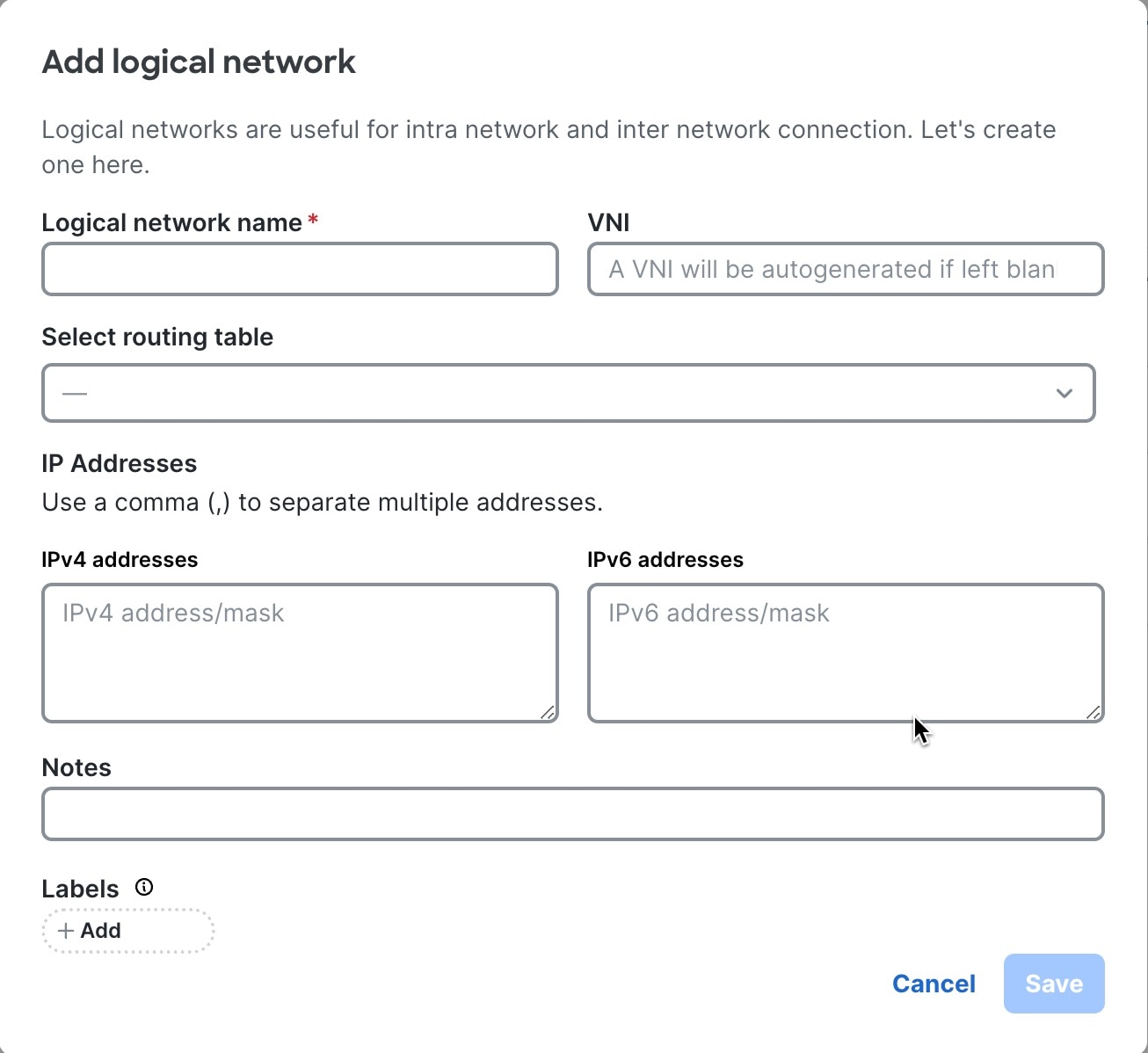
|
Step 5 | Configure a logical network.
|
Step 6 | The logical network (VNI) is displayed in the Logical network table. For a Layer 2 logical network, you can view the name and VNI number. For a Layer 3 logical network you can view the name, VNI number, and IPv4 and/or IPv6 IP addresses. For Layer 3 logical network, IP address is also displayed in the SVI table at the VRF level. Follow the following steps to view the SVI table.
|
Add a VLAN member to a logical network
A logical network is deployed by adding a VLAN member. A VLAN member maps a logical network to switch(s), port interface(s), port channel(s), and VLAN (tagged or untagged). After you add a VLAN member, the traffic coming from the switch, interface, and VLAN will be mapped to the logical network.
Follow these steps to add a VLAN member to an existing logical network.
Step 1 | Select Fabrics, then select the fabric to configure. |
Step 2 | If the fabric is not in the edit mode, select Switch to edit mode. |
Step 3 | In the Attachments area, select VLAN memberships. |
Step 4 | Select + Add a VLAN membership. 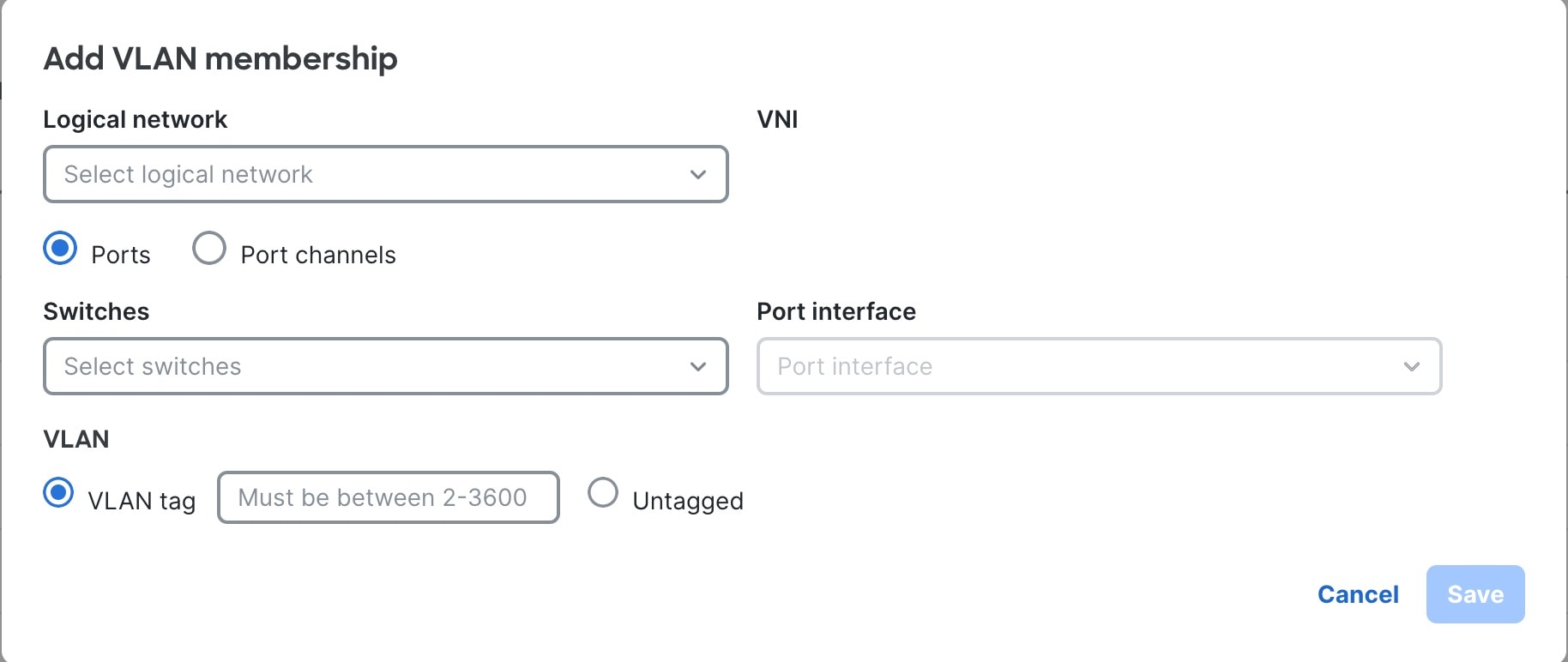
|
Step 5 | Select an existing logical network from the Logical network drop-down list. The VNI number for the selected network appears under VNI. |
Step 6 | Select an individual switch or select * to select all switches from the Select switch drop-down list. |
Step 7 | Select an individual port or port channel from the Port interface drop down list. |
Step 8 | Select VLAN tag and enter a VLAN number between 2 and 3800, or select Untagged. Nexus Hyperfabric allows you to configure a port as both native (untagged) as well as tagged (VLAN IDs 2-3800). When traffic with the configured tag arrives on the selected interface on the selected switch, it will be mapped to this logical network.
|
Step 9 | Select Save. The VLAN members are displayed in the VLAN membership table. |
Create a route table (VRF)
A route table is a data table stored in a Layer 3 switch that lists the routes to particular network destinations. The route table contains information about the topology of the network immediately around it. It is used to determine the best path for forwarding packets to their destination.
Virtual Route Forwarding (VRF) is a technology that allows having more than one route table on a single router or Layer 3 switch. In Nexus Hyperfabric, you can create multiple route tables on a single fabric.
Step 1 | Select Fabrics, then select the fabric to configure. |
Step 2 | If the fabric is not in the edit mode, select Switch to edit mode. |
Step 3 | In the Logical network area, select Route tables (VRF). |
Step 4 | Select + Add a route table. 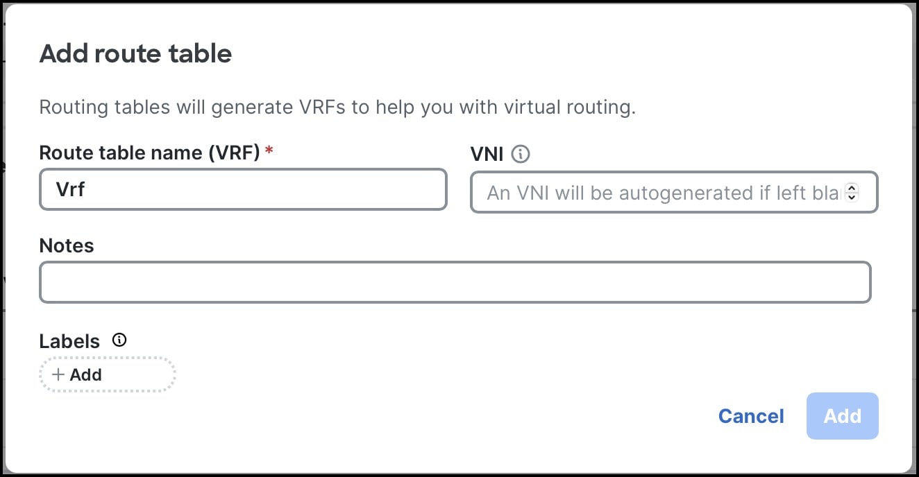
|
Step 5 | Select Add. The route table is displayed in the All route tables (VRF) area. |
Add a static route
Routers forward packets using route information from route table entries that you manually configure or from the route information that is calculated using dynamic routing algorithms.
Ensure these configurations exist prior to adding a static route:
- route table (VRF)
- loopback IP range if enabling IP SLA probes or DHCP relay profiles
Follow these steps to add a static route.
Step 1 | Navigate to the VRF where you want to configure static routes.
|
Step 2 | In the Configurations area, select Static routes. |
Step 3 | Select + Add a static route.
|
Add a routed interface
When you configure a routed port (interface) on a switch, you can choose to enable VLAN tagging, which requires you to configure 802.1Q VLAN sub-interfaces on a Layer 3 interface to forward IPv4 and IPv6 packets to another device using static or dynamic routing protocols. Alternatively, if you leave VLAN tagging disabled, you can choose a route table (VRF) and specify IPv4 addresses or IPv6 addresses for the routed interface.
This procedure configures a routed port at the switch level, but you can also configure a routed port at the fabric level.
Follow these steps to configure a routed port.
Step 1 | Navigate to the switch you are interested in.
|
Step 2 | In the Configure area, select Port configurations. The Port configurations table lists all ports of the switch. |
Step 3 | In the Action column, select ( |
Step 4 | In the Port configuration for switch_name, select Routed as the port role. |
Step 5 | To use VLAN tagging, enable Enable VLAN tagging. The SUB-INTERFACES configuration area appears. Perform these substeps for each sub-interface.
|
Step 6 | If you do not want to use VLAN tagging, disable Enable VLAN tagging and perform these substeps.
|
Step 7 | For Admin state, select the desired administrative state. |
Step 8 | Select Save. |
 ) for the port that you want to configure.
 Create a DHCP relay profile
A DHCP relay allows DHCP communication between hosts and remote DHCP servers that are not on the same network. When a host sends a DHCP broadcast for an IP address, the DHCP relay agent forwards the request to the subnet of the remote DHCP server. DHCP server dynamically assigns IP addresses.
Nexus Hyperfabric relays the request from the host to the DHCP server and relays the offer from the DHCP server to the host. To allow for this communication, you have to create a DHCP relay profile in Nexus Hyperfabric.
The DHCP relay supports:
- only IPv4 address family
- DHCP relay is applicable to one or more logical networks with SVIs
- DHCP server in the same VRF as the relay
- DHCP server can be inside or outside of the fabric
Ensure a route table (VRF) exists for the DHCP relay profile.
Step 1 | Select Fabrics, then select the fabric to configure. |
Step 2 | If the fabric is not in the edit mode, select Switch to edit mode. |
Step 3 | In the Logical network area, select Route tables (VRF). |
Step 4 | Select the route table name where you will add a DHCP relay profile. |
Step 5 | In the Configurations area, select DHCP relay profiles. If DHCP profiles have already been created in this VRF, a list of existing profiles is displayed. |
Step 6 | In the Loopback IPv4 range area, select This is the loopback IP address range for Nexus Hyperfabric switches that will forward DHCP requests. A Unique loopback IP address is automatically allocated to Nexus Hyperfabric switches that have the logical network with the DHCP profile associated. The loopback IP addresses should be reachable from the DHCP server. For example, if the DHCP server is outside the fabric behind an external router, then the loopback IP address range needs to be advertised to the external network. Otherwise, the return traffic from the DHCP server will be dropped before coming back to the fabric.  Note NoteIf you use BGP to advertise fabric subnets to the external network, make sure that the loopback IP addresses are permitted in your BGP export policy. |
Step 7 | Select + Add a DHCP relay profile. 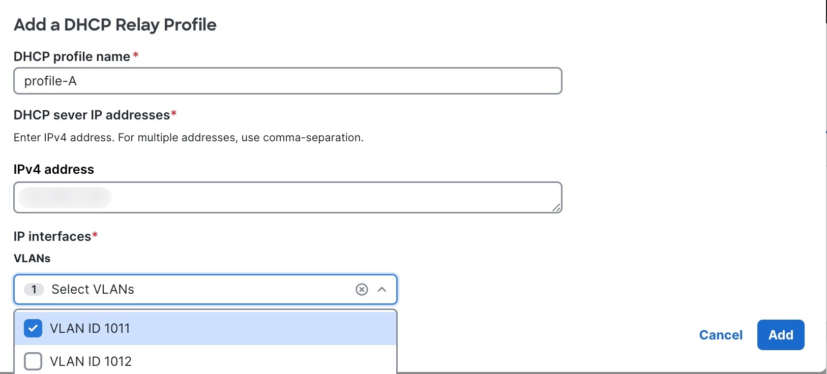
|
Associate a Layer 3 logical network to an existing DHCP relay profile
The switch virtual interface (SVI) represents a logical interface between the bridging function and the routing function of a VLAN in the device. SVI can have members that are physical ports or port channels. The SVI logical interface is associated with VLANs, and the VLANs have port membership.
In Nexus Hyperfabric associating a Layer 3 logical network to a DHCP relay profile to allows the host to talk to DHCP server using SVI.
NoteYou must create DHCP relay profile before associating with a Layer 3 logical network.
Follow these steps to associate a Layer 3logical network to an existing DHCP relay profile.
Step 1 | Select Fabrics, then select the fabric to configure. |
Step 2 | If the fabric is not in the edit mode, select Switch to edit mode. |
Step 3 | In the Logical network area, select Route tables. |
Step 4 | Select a route table (VRF). |
Step 5 | In the Configurations area, select SVIs. |
Step 6 | Select Add a SVI. 
Optionally, in the Action column, select
|
Create a loopback interface
Loopback interfaces provide a stable, always-up IP address for device management and identification. Even if physical interfaces go down, the loopback interface remains available.
Loopback interfaces in Cisco Nexus Hyperfabric are created in two ways:
- Automatically created loopback interfaces: Loopback interfaces are created automatically when a loopback IP range is defined as part of a DHCP relay profile. You can view the automatically assigned IP addresses and switches in the Loopback interfaces table.
- Manually created loopback interfaces: You can manually assign a loopback address for various purposes. These can include providing a consistent source IP address for establishing multihop BGP sessions, or helping to verify routing and connectivity within a specific VRF. In BGP multihop scenarios, the loopback address is especially important: it acts as a consistent endpoint for BGP sessions that span multiple network hops. By using a loopback address as the BGP source and destination, the session remains resilient to link failures on individual physical interfaces, as long as the device itself is reachable.
Follow these steps to manually create a loopback interface.
Step 1 | Select Fabrics, then select the fabric to configure. |
Step 2 | In the Logical network area, select Route tables (VRF). |
Step 3 | In the All route tables (VRF), select the name of the route table in which you want to create loopback interfaces. |
Step 4 | In the Configurations area, select Loopback interfaces. |
Step 5 | Select + Add loopback interface.
|
Step 6 | Select Add. The loopback interface is displayed in the Loopback interfaces table. |
Manage logical networks
Follow these steps to edit or delete a logical network.
Step 1 | Select Fabrics, then select the fabric to configure. |
Step 2 | If the fabric is not in the edit mode, select Switch to edit mode. |
Step 3 | In the Logical network area, select Logical networks (VNI). The Logical networks (VNI) table lists all the logical networks of the fabric. |
Step 4 | Edit or delete a logical network. In the Action column of a logical network row, choose one of these options:
|
 , then select
 Manage VLAN members
Follow these steps to edit or delete a VLAN member.
Step 1 | Select Fabrics, then select the fabric to configure. |
Step 2 | If the fabric is not in the edit mode, select Switch to edit mode. |
Step 3 | In the Logical network area, select Logical networks (VNI). |
Step 4 | Select a logical network and in the Monitor area, select VLAN membership. The VLAN membership table lists all the VLAN members. |
Step 5 | Edit or delete a VLAN member. In the Action column of a VLAN member row, choose one of these options:
|
Manage SVIs
Follow these steps to edit a SVI.
Step 1 | Select Fabrics, then select the fabric to configure. |
Step 2 | If the fabric is not in the edit mode, select Switch to edit mode. |
Step 3 | In the Logical network area, select Route tables (VRF). |
Step 4 | Select a route table and in the Configurations area, select SVIs. |
Step 5 | Edit or delete a SVI. In the Action column of a SVI row, choose one of these options:
|
Manage route tables
Follow these steps to edit or delete a route table (VRF).
Step 1 | Select Fabrics, then select the fabric to configure. |
Step 2 | If the fabric is not in the edit mode, select Switch to edit mode. |
Step 3 | In the Logical network area, select Route tables (VRF). The All route tables (VRF) table lists all the route tables. |
Step 4 | Edit or delete a route table. In the Action column of a route table row, choose one of these options:
|
Manage routed interfaces
Follow these steps to edit a routed interface.
Step 1 | Select Fabrics, then select the fabric to configure. |
Step 2 | If the fabric is not in the edit mode, select Switch to edit mode. |
Step 3 | In the Logical network area, select Route tables (VRF). |
Step 4 | Select a route table and in the Configurations area, select Routed interfaces. |
Step 5 | Edit or delete a routed interface. In the Action column of a routed interface row, choose one of these options:
|
Manage DHCP relay profiles
Follow these steps to edit or delete a DHCP relay profile.
Step 1 | Select Fabrics, then select the fabric to configure. |
Step 2 | If the fabric is not in the edit mode, select Switch to edit mode. |
Step 3 | In the Logical network area, select Route tables (VRF). |
Step 4 | Select a route table and in the Configurations area, select DHCP relay profiles. |
Step 5 | Edit or delete a DHCP relay profile. In the Action column of a DHCP relay profile row, choose one of these options:
|
Manage loopback interfaces
Loopback interfaces can be created in two ways: manually by the user or dynamically on switches when a loopback IP range is defined as part of a DHCP relay profile. All loopback interfaces (including those that are dynamically assigned) are shown in the Loopback interfaces table allowing you to see which loopback IPs are assigned to each switch and VRF. However, only user-created loopback interfaces can be edited or deleted.
Follow these steps to edit or delete the IP address of a loopback interface.
Step 1 | Select Fabrics, then select the fabric you want to configure. |
Step 2 | In the Logical network area, select Route tables (VRF). |
Step 3 | In the All route tables (VRF) table, select the name of the route table that contains the loopback interface you want to configure. |
Step 4 | In the Configurations area, select Loopback interfaces. |
Step 5 | Edit or delete a loopback interface. In the Action column of a loopback interface row, choose one of these options:
|
Manage anycast gateway MAC addresses
The MAC address is the fabric wide value used by all of switch virtual interfaces (SVIs) owned by the fabric.
Starting in July 2026, the default anycast gateway MAC address on the Cisco Nexus Hyperfabric is AE:00:00:00:00:01. Prior to July 2026, the default MAC address was AE:00:xx:xx:xx:xx, where xx:xx:xx:xx was automatically selected and unique for each fabric.
Follow these steps to manage anycast gateway MAC addresses.
Step 1 | Select Fabrics, then select the fabric to configure. |
Step 2 | If the fabric is not in the edit mode, select Switch to edit mode. |
Step 3 | In the Logical network area, select Logical networks (VNI). |
Step 4 | Next to Anycast gateway MAC address, select |
Step 5 | Enter a new MAC address and select Save. |
Limitations for anycast gateway MAC addresses
These limitations apply for anycast gateway MAC addresses:
- The MAC address must not be a broadcast or multicast address.
-
The MAC address must not be from a reserved range. These are the reserved MAC address ranges:
- ae-00
- ae-10
- de-ad
Spanning tree protocol
Spanning tree protocol (STP) prevents loops from being formed when switches or bridges are interconnected using multiple paths. Spanning tree protocol implements the 802.1D IEEE algorithm by exchanging Bridge Protocol Data Unit (BPDU) messages with other switches to detect loops, and then removes the loop by shutting down selected bridge interfaces. This algorithm guarantees that there is one and only one active path between two network devices.
By default, global STP is disabled on Nexus Hyperfabric. If global STP is disabled, host ports will drop BPDU messages. If global STP is enabled, Nexus Hyperfabric uses per-VLAN spanning tree plus (PVST+) and uses the same bridge ID for all the Nexus Hyperfabric switches.
STP recommendations
Follow these recommendations if you enabled global STP:
- Nexus Hyperfabric is the root bridge.
- Enable root guard on all host ports.
- Enable STP on all host ports with STP PortFast enabled and BPDU guard disabled.
Regardless of global STP status, non-host ports never transmit BPDU messages. As a result, BPDU messages are not transmitted to Nexus Hyperfabric overlay network. We recommend that you use Nexus Hyperfabric as the root bridge instead of relying on an external root bridge for loop prevention.
Since root guard supports per VLAN and auto-recovery, we recommend that you enable root guard to protect against an unexpected external root.
Even with STP PortFast enabled, if the port receives BPDU messages and BPDU guard is disabled, PortFast is disabled automatically and the BPDU messages will go through the regular STP learning state.
Because BPDU guard does not support per VLAN or auto-recovery, we recommend that you disable it. If a port is in the err-disable state because of BPDU guard, you must disable and then enable the port to recover it, which affects all VLANs on the port.
Enable spanning tree protocol on a fabric
Configuring spanning tree protocol (STP) involves enabling STP on the entire fabric and configuring the STP options for any ports with which you want to use STP.
Follow these steps to enable spanning tree protocol on a fabric.
Step 1 | Select Fabrics, then select the fabric that contains the switches. |
Step 2 | If the fabric is not in the edit mode, select Switch to edit mode . |
Step 3 | In the Attachments area, select Global spanning tree. |
Step 4 | Select Configure and follow these substeps.
|
Configure spanning tree protocol at the fabric level
To configure spanning tree protocol (STP), you must first enable STP on the entire fabric and then configure the STP options for each port. This procedure configures STP at the fabric level, but you can also configure STP at the switch level.
If you want to configuration STP on a port channel, see Configure spanning tree protocol on an existing port channel.
Follow these steps to configure spanning tree protocol at the switch level.
Step 1 | Enable STP on the fabric. |
Step 2 | In the Physical Topology area of the fabric's page, select Port configurations. |
Step 3 | In the Action column, select the edit button (
|
Step 4 | Select Save. |
Configure spanning tree protocol when configuring a port channel
You can configure spanning tree protocol (STP) when you configure a port channel. To do this, you must first enable STP on the entire fabric and then configure STP when you configure the port channel.
Follow these steps to configure spanning tree protocol when configuring a port channel.
Step 1 | Enable STP on the fabric. |
Step 2 | In the Attachments area of the fabric's page, select Port channel. A table of existing port channels appears. 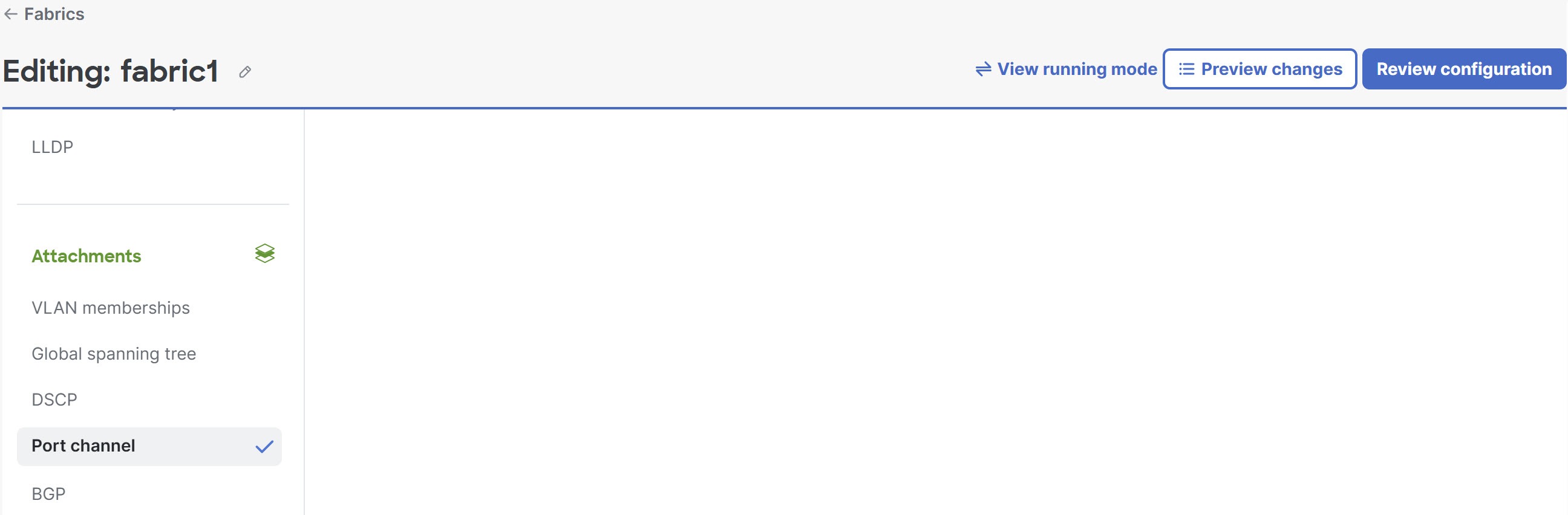
|
Step 3 | Select + Add port channel and follow these substeps to add the port channel. 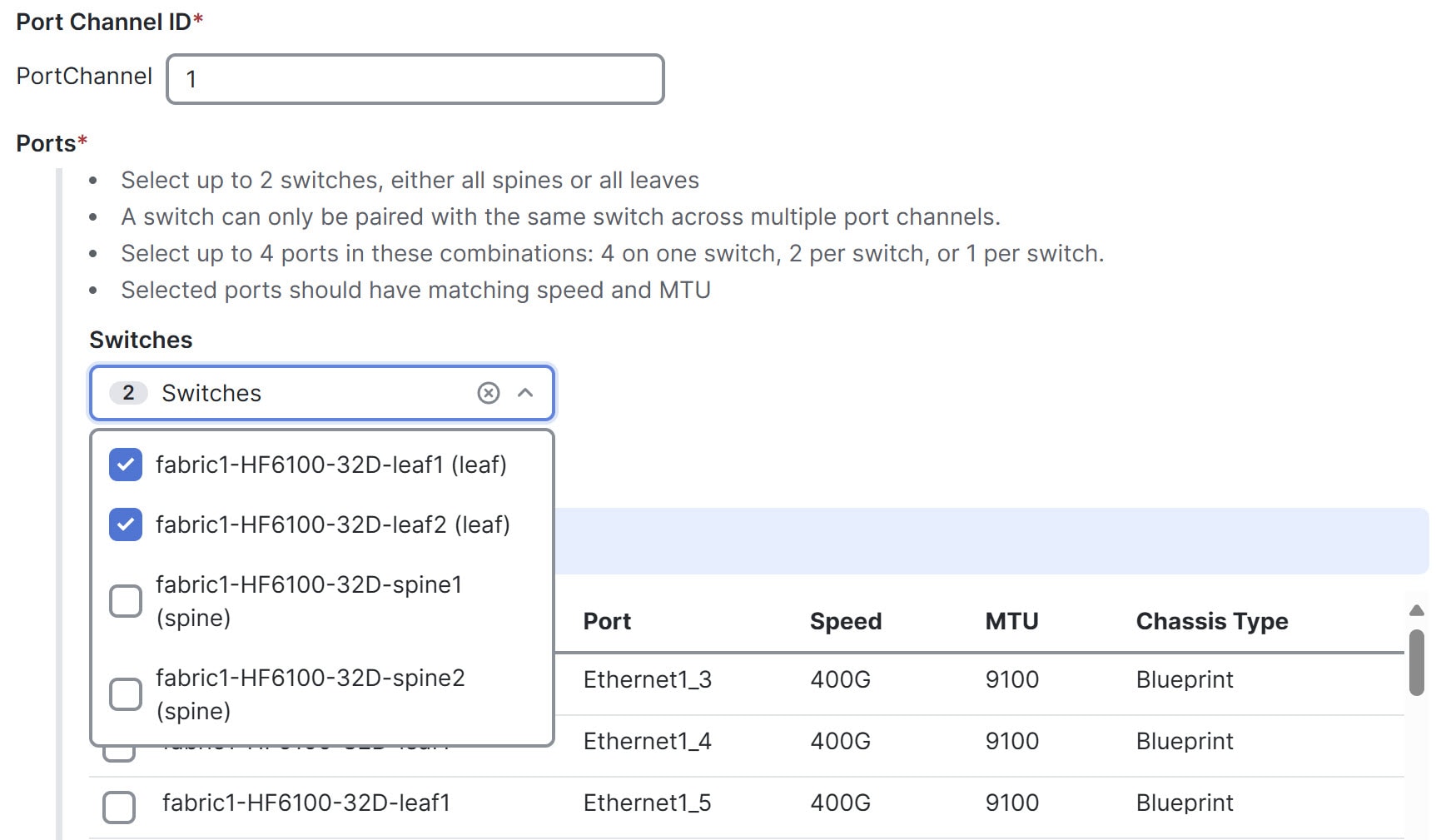
|
Configure spanning tree protocol on an existing port channel
You can configure spanning tree protocol (STP) on an existing port channel. To do this, you must first enable STP on the entire fabric and then configure STP on the port channel.
Follow these steps to configure spanning tree protocol on an existing port channel.
Step 1 | Enable STP on the fabric. |
Step 2 | In the Attachments area of the fabric's page, select Port channel. A table of existing port channels appears. 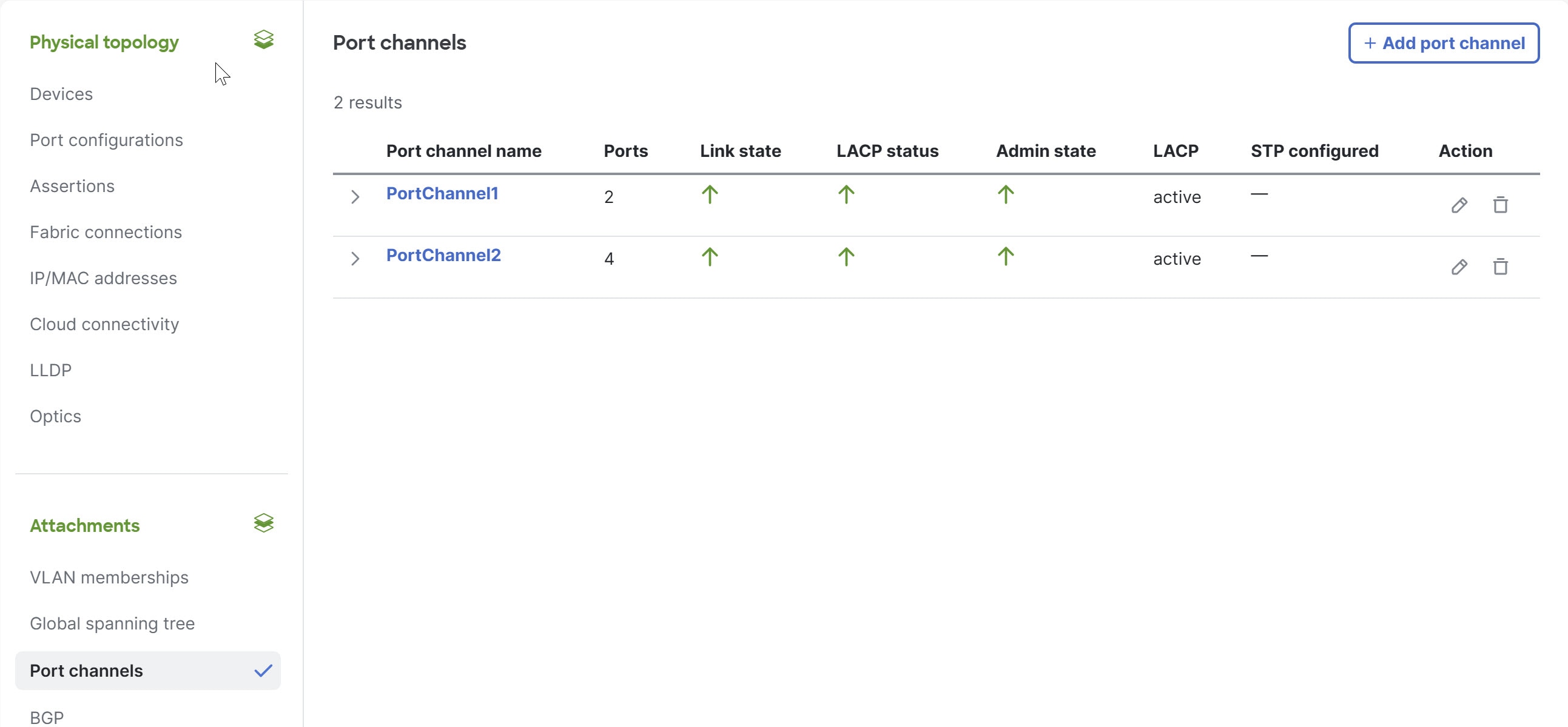
|
Step 3 | In the Action column, select the edit button (
|
Finish and commit your changes
Your changes are not applied to the fabric until you review, commit, and push them.
NoteFor a more detailed description of this procedure, see "Workflow for making changes to the fabric" in Cisco Nexus Hyperfabric—Getting Started.
Follow these steps to finish and commit your changes.
Step 1 | Select Review configuration. 
|
Step 2 | Verify your changes in the review list. |
Step 3 | Select Comment and push. |
Step 4 | In the Comment before pushing configuration dialog box, enter the reason for the change. |
Step 5 | Select Push configuration. |