
Cisco Nexus Hyperfabric — Switches
Configuring the switches and ports
The Blueprint Designer provides the basic design and port configuration for the fabric. During the fabric design phase or after fabric deployment, you can perform general configuration tasks. For example, you can enable host ports for your network devices, create routed ports for external connections, or add sub-interfaces. To configure and apply your changes, ensure that you are in edit mode and that you commit your changes.
Modify a switch configuration
Step 1 | Navigate to the switch you are interested in.
 |
Step 2 | In the Configure area, select a switch property to view or modify. 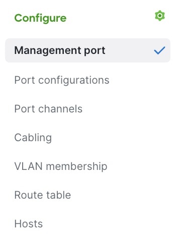 |
Step 3 | Configure the selected switch property. The configuration procedures are described in these links.
|
Configure the management interface of a switch
You typically configure the management interface and Craft console password prior to onboarding, but you may configure or modify these parameters after onboarding. You may want to modify the management interface configuration to update the IP addressing scheme, improve security settings, or adjust operational parameters.
Step 1 | Choose Fabrics, then select the fabric that has the switch you want to modify. |
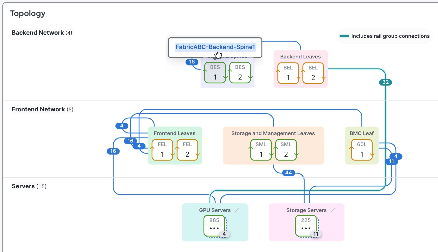
Step 2 | In the Topology area, select the switch you want to configure, then select the switch name. |
Step 3 | In the Configure area, select Management port. 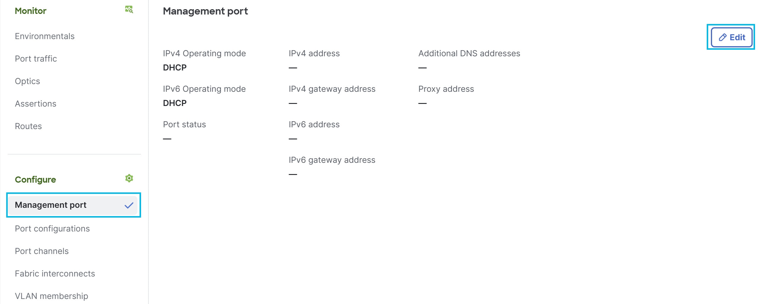
|
Step 4 | Select Edit. |
Step 5 | In the Edit management ports dialog box, select how the management port obtains IP addresses. At least one IPv4 or IPv6 address is required for cloud connectivity.
|
Step 6 | (Optional) Enter Proxy address , Proxy username , and Proxy password. |
Step 7 | (Optional) In the Forgot your console password? area, enter the new password in both fields, then select Update. For more information, see Change the Craft console password of a switch. |
Step 8 | Select Update. |
Managing switch ports
Dynamic port breakout
Dynamic port breakout enables you to divide a high-speed, channelized port on a network element into multiple low-speed ports. Each low-speed port can connect to a different network element, maximizing the use of the high-speed port's bandwidth. Breakout is suitable for very short links and offers a cost effective way to connect within racks and across adjacent racks. For example, you can split a 400 Gigabit (Gb) port into four independent and logical 100Gb ports.
You configure breakout on the down links (also known as the access-facing ports or downlink ports) and fabric links of the switches. Fabric links form the connections between switches.
For how to configure a port breakout, see Configure a port at the switch level.
View the ports of a switch
After you configure the ports of a switch, you can look at the status of all ports. At a glance, you can see which ports are up, not connected, disabled, or configured for breakout.
Follow these steps to view the ports of a switch.
Step 1 | Navigate to the switch you are interested in.
|
Step 2 | In the Ports area, select Port status or Face plate. 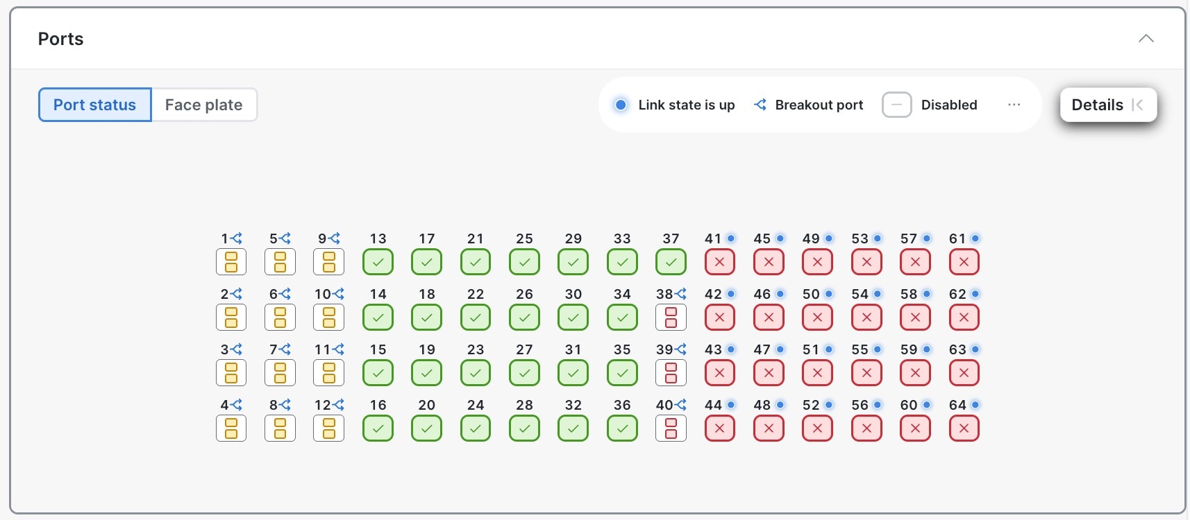
|
Step 3 | To see a list of all ports on the switch, in the Configure area, select Port configurations. See Configure a port at the switch level. |
Step 4 | To see details about a specific port:
|
Guidelines for configuring ports
With the Cisco HF6100-60L4D switch, when you configure the speed of one of the SFP56 ports in a port group, the speed of the other port gets configured with the same speed.
Configure a port at the switch level
You can configure various properties of a switch's port, such as the role and speed, and breakout status. The port role specifies the type of connection provided by a port.
Follow these steps to configure a port at the switch level.
Step 1 | Choose Fabrics, then select the fabric that contains the switch. |
Step 2 | If the fabric is not in the edit mode, select Switch to edit mode. |
Step 3 | In the Topology area, select the switch you want to configure, then select the switch name. |
Step 4 | In the Configure area, select Port configurations. The Port configurations table lists all ports of the switch. 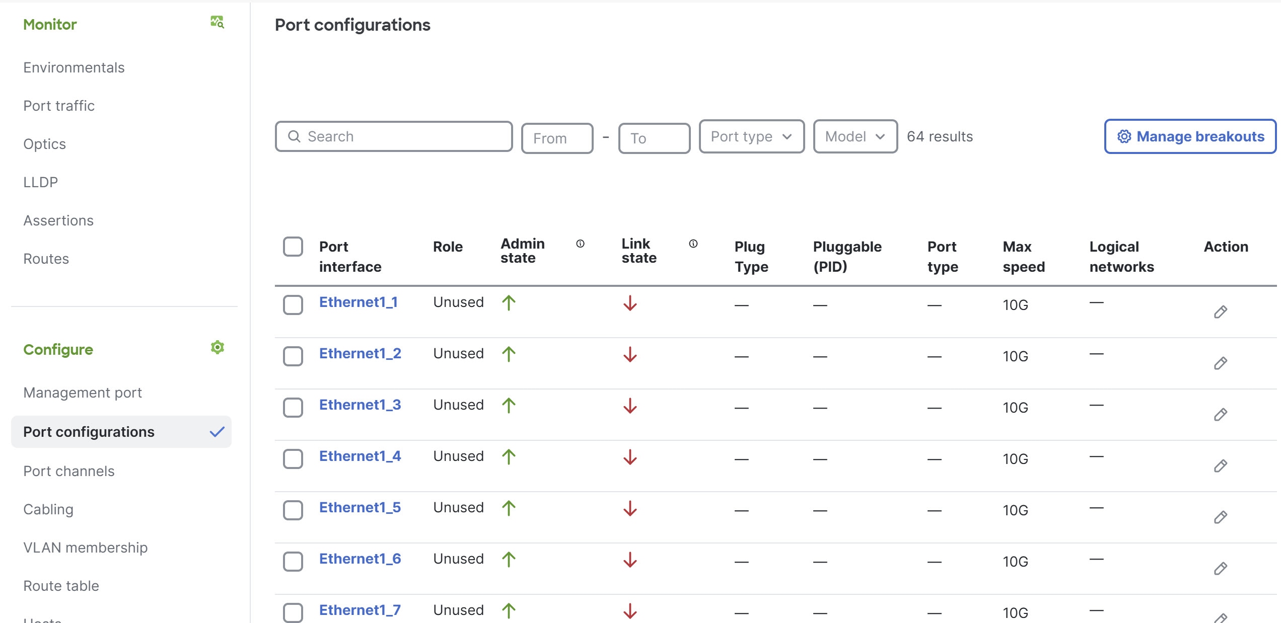
|
Step 5 | (Optional) If you want to enable or disable breakout for any of the ports, select Manage breakouts.
|
Step 6 | In the Port configurations table, under the Action column, select edit ( A dialog box opens for configuring the port. 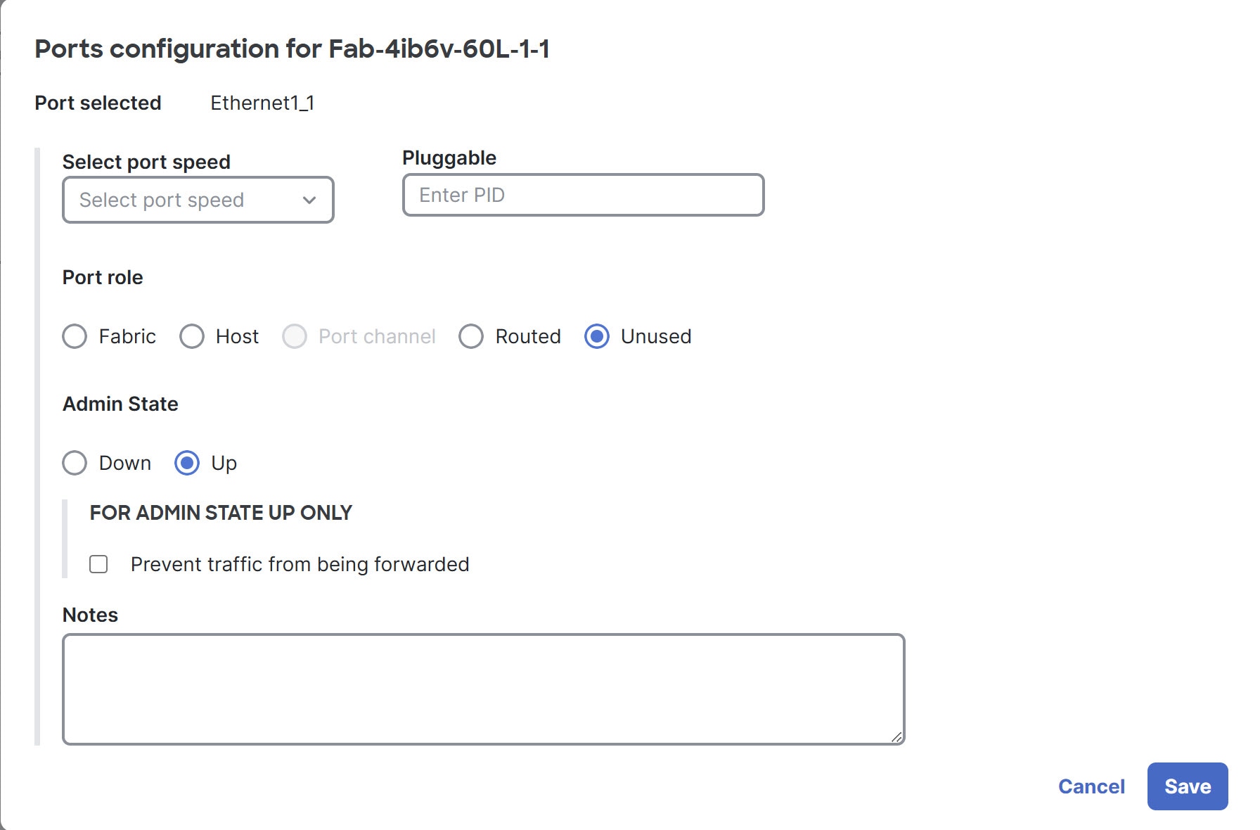
|
Step 7 | Repeat the previous step for every port on this switch that will connect to another leaf or spine switch or host in the fabric. |
Step 8 | Repeat this procedure for every leaf or spine switch in the fabric. |
 ) for the port that you want to configure.
Configure multiple ports at the switch level
You can configure various properties of multiple ports of a switch simultaneously, such as the role and speed. The port role specifies the type of connection provided by a port.
Some property choices reveal additional properties that you cannot set with this procedure. To configure these additional properties, you must configure the ports individually. The descriptions in each step indicate which properties have this limitation.
Follow these steps to configure multiple ports at the switch level.
Step 1 | Choose Fabrics, then select the fabric that contains the switch. |
Step 2 | If the fabric is not in the edit mode, select Switch to edit mode. |
Step 3 | In the Topology area, select the switch you want to configure, then select the switch name. |
Step 4 | In the Configure area, select Port configurations, then select the ports that you want to configure by putting a check in the box next to each port ID. 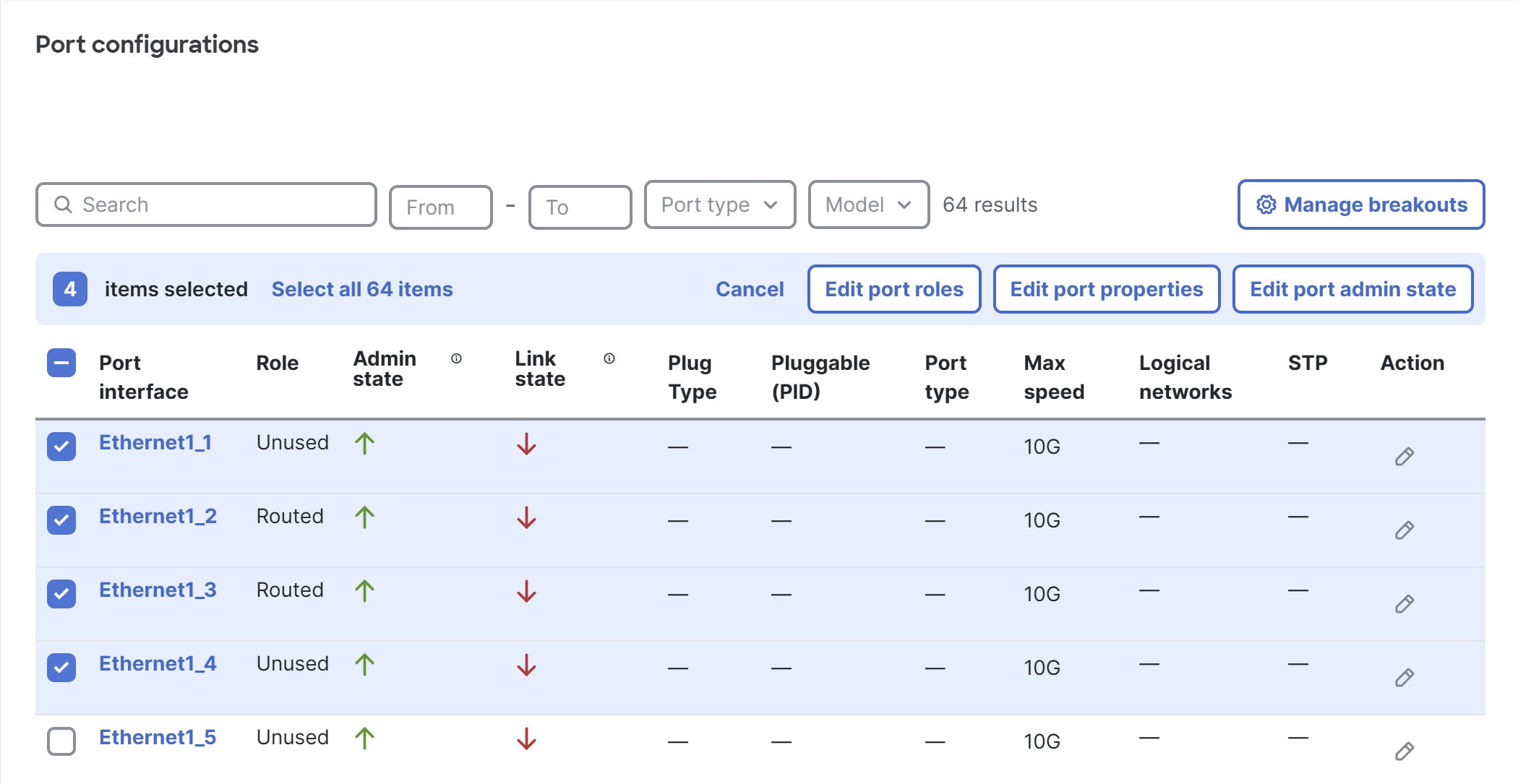
|
Step 5 | To change the role of the ports, select Edit port roles.
|
Step 6 | To change port properties, select Edit port properties. These properties include port speed and pluggable options.
|
Step 7 | To change the administrative state, select Edit port admin state.
|
Configure a switch port at the fabric level
You can configure any port of any switch in a fabric by going to the Physical topology area of that fabric. This page makes it easy to configure the ports of different switches.
Follow these steps to configure a port at the fabric level.
Step 1 | Choose Fabrics, then select the fabric that contains the switch for which you want to configure its ports. |
Step 2 | If the fabric is not in the edit mode, select Switch to edit mode. |
Step 3 | In the Physical topology area, select Port configurations. The Port configurations table lists all ports of all switches in the fabric. |
Step 4 | Above the Port configurations table, you can use the various fields and drop-down lists to filter the table.
|
Step 5 | In the Action column, select edit (
|
Configure multiple switch ports at the fabric level
You can configure any switch port in a fabric by going to the Physical topology area of that fabric. This page makes it easy to configure the ports of multiple switches simultaneously.
Some property choices reveal additional properties that you cannot set with this procedure. To configure these additional properties, you must configure the ports individually. The descriptions in each step indicate which properties have this limitation.
Follow these steps to configure multiple ports at the fabric level.
Step 1 | Choose Fabrics, then select the fabric that contains the switches for which you want to configure their ports. |
Step 2 | If the fabric is not in the edit mode, select Switch to edit mode. |
Step 3 | In Physical topology, select Port configurations. The Port configurations table lists all ports of all switches in the fabric. |
Step 4 | Above the Port configurations table, you can use the various fields and drop-down lists to filter the table.
|
Step 5 | Select the ports that you want to configure by checking the box next to each port ID. The ports can belong to different switches. |
Step 6 | To change the role of the ports, select Edit port roles.
|
Step 7 | To change the port properties, select Edit port properties. The properties include the port speed and pluggable.
|
Step 8 | If you want to change the admininistrative state, select Edit port admin state.
|
Change the Craft console password of a switch
Follow these steps to change the Craft console password of a switch.
Step 1 | Choose Fabrics, then click the fabric that contains the switch. |
Step 2 | In the Topology area, click the switch for which you want to change the Craft console password, then click the switch name. |
Step 3 | In the Configure area, click Management port, then click Edit. |
Step 4 | In the Forgot your console password? area, enter the new password in both fields, then click Update. |
What to do next
Push the configuration change. For more information, see Finish and commit your changes.
Limitations of changing the Craft console password of a switch
These limitations apply to changing the Craft console password of a switch:
- Switch must be connected to the Cisco Nexus Hyperfabric.
- Only an administrator can change the password.
Cabling
Cisco Nexus Hyperfabric automatically determines how you should cable the devices in a fabric based on the number of connections per device pair and cabling strategy. The cabling strategy comprises two notions.
The first notion comprises these things:
- Strict: Cisco Nexus Hyperfabric connects each device pair with the number of connections that you selected. If a device does not have enough available ports for any reason, Cisco Nexus Hyperfabric indicates that there is an error with the cabling.
- Best effort: Cisco Nexus Hyperfabric connects each device pair with the number of connections that you selected if possible. However, if a device does not have enough available ports for any reason, Cisco Nexus Hyperfabric connects the devices in the pair to other devices in the same switch group that have enough available ports.
The second notion comprises these things:
-
Dense: Cisco Nexus Hyperfabric connects consecutive ports of a device to consecutive ports of a paired device. The number of consecutive ports is equal to the number of connections per device pair that you selected. Cisco Nexus Hyperfabric repeats this connecting of consecutive ports for each successive paired device. This is used for switch-to-switch connections.
Switch-to-switch dense cabling strategy with two spine switches and two leaf switches 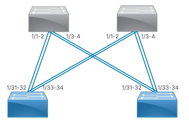
-
Distributed: Cisco Nexus Hyperfabric connects the first network interface card (NIC) of the first server to the first port of the first switch, then the second NIC of the server to the first port of the second switch, and so on until the server has one connection to the first port of each switch. Cisco Nexus Hyperfabric repeats this process with the successive servers, but the NICs connect to the successive port of each switch. After each servers' NICs are connected to each switch, the entire process repeats until there are a number of connections from each server to each switch equal to the specified number of connections.
Server port groups that have GPUs also use the distributed cabling strategy. In the rail group properties, these servers have width equal to the number of GPU servers and a count of 8.
With or without GPUs, the same NIC number on each server connects to the same switch. Thus, for a fabric with two servers (server1 and server2) and two switches (switch1 and switch2), NIC1 of both servers connect to switch1 while NIC2 of both servers connect to switch2.
Switch-to-server distributed cabling strategy with two leaf switches and two servers 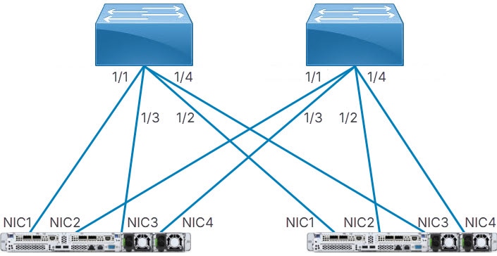
If your fabric includes connections between devices in the same switch group or server group, Cisco Nexus Hyperfabric allocates ports to device pairs in different groups first, then allocates ports to devices in the same group.
Server cabling
For uplink redundancy with servers that do not have GPUs, the cabling strategy is always distributed. The connections go from the ports of the switches to the ports of the network interface cards (NICs) of the servers.
Server port groups that have GPUs also use the distributed cabling strategy. In the rail group properties, these servers have width equal to the number of GPU servers and a count of 8.
In either case, the same NIC number on each server connects to the same switch. Thus, for a fabric with two servers (server1 and server2) and two switches (switch1 and switch2), NIC1 of both servers connect to switch1 while NIC2 of both servers connect to switch2.
Because switch-to-server connections are distributed, each subsequent NIC of a server connects to a different switch until all switches have one connection from different NICs of each server. After that, the next NIC of each server connects to the first switch and the process repeats.
Continuing the example, if you selected two connections, server1 has these connections:
- NIC1 to switch1
- NIC2 to switch2
- NIC3 to switch1
- NIC4 to switch2
Server2 has the same connections, but to different ports of the switches.
View cabling topology
You can view a graphical representation of the cables in a fabric and related device group connection information.
Step 1 | Choose Fabrics, then select the fabric you want to view cabling for. Cable connections appear as colored lines joining different device groups. Each number on a cable indicates the number of connections between device groups. 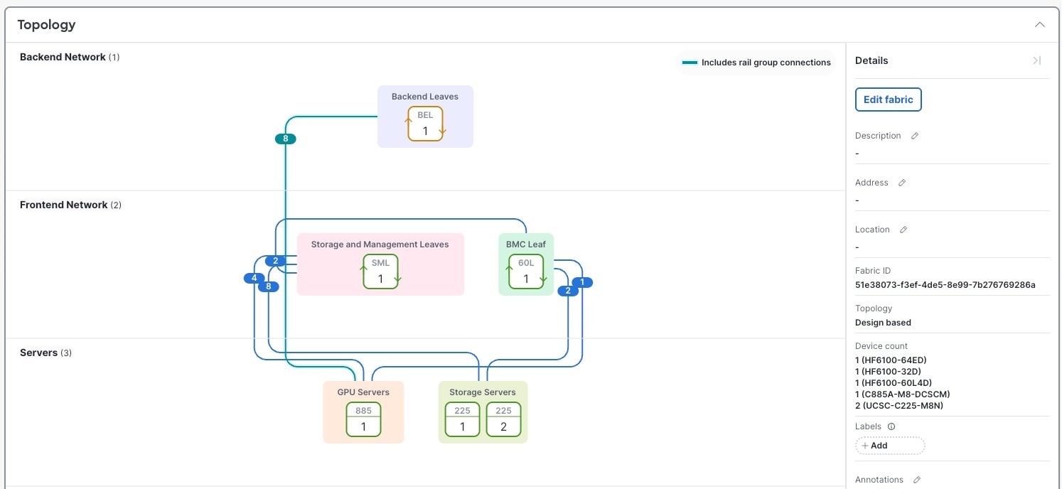 |
Step 2 | Select the number on a cable you are interested in. The Cabling drawer lists all connections for the selected cable. Each connection shows the device group names, device names, and interfaces. 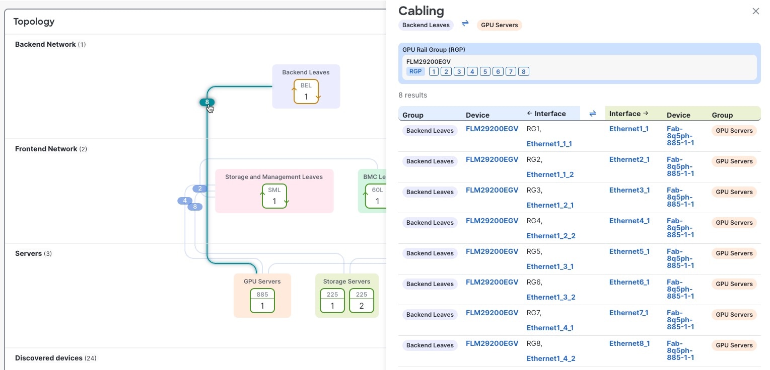 |
Modify cabling
You can view, export, and modify all fabric connections associated with a switch.
Step 1 | Navigate to the switch you are interested in.
|
Step 2 | In the Configure area, select Cabling. The Cabling table lists all fabric connections associated with the switch. To export this list, select Export CSV. |
Step 3 | Select Edit cabling. |
Step 4 | To modify switch group connections:
|
Step 5 | To modify rail groups, you can add a new rail group or modify these fields:
|
Step 6 | To modify server port group to switch group connections, you can edit these fields:
|
Step 7 | Select Save fabric blueprint to save configuration changes. |
Step 8 | Select Run cabling to apply configuration changes. |
Finish and commit your changes
Your changes are not applied to the fabric until you review, commit, and push them.
 Note
NoteFor a more detailed description of this procedure, see "Workflow for making changes to the fabric" in Cisco Nexus Hyperfabric—Getting Started.
Follow these steps to finish and commit your changes.
Step 1 | Select Review configuration. 
|
Step 2 | Verify your changes in the review list. |
Step 3 | Select Comment and push. |
Step 4 | In the Comment before pushing configuration dialog box, enter the reason for the change. |
Step 5 | Select Push configuration. |