Altitude Requirements
Altitude rating is 10,000 ft (3048 m). For China, it is 6,562 ft (2000 m).
The documentation set for this product strives to use bias-free language. For the purposes of this documentation set, bias-free is defined as language that does not imply discrimination based on age, disability, gender, racial identity, ethnic identity, sexual orientation, socioeconomic status, and intersectionality. Exceptions may be present in the documentation due to language that is hardcoded in the user interfaces of the product software, language used based on RFP documentation, or language that is used by a referenced third-party product. Learn more about how Cisco is using Inclusive Language.
The switch is positioned with its ports in either the front or the rear of the rack, depending on your cabling and maintenance requirements. To identify the airflow options for your switch, see the user-replaceable components in the Overview section of this document. Position the fan and power supply modules to move the coolant air from the cold aisle to the hot aisle in one of these ways:
Port-side exhaust airflow: Cool air enters the chassis through the fan and power supply modules in the cold aisle and exhausts through the port end of the chassis in the hot aisle.
Port-side intake airflow: Cool air enters the chassis through the port end in the cold aisle and exhausts through the fan and power supply modules in the hot aisle.
Single-direction airflow: The direction of the installed fan modules determines the airflow.
For port-side exhaust airflow, the N9348Y12C-SE1switch can support QSFP-100G-SR1.2 on rows 1 and 3 at a maximum ambient temperature of 35°C and on row 2 at a maximum ambient temperature of 30°C. It can also support QSFP-100G-SM-SR and QSFP-40/100-SRBD on rows 1, 2, and 3 at a maximum ambient temperature of 35°C.
For port-side intake airflow, there is no limitation.
You can identify the airflow direction of each fan and power supply module by its coloring.
 Note |
To prevent the switch from overheating and shutting down, position the air intake for the switch in a cold aisle. The fan and power supply modules must have the same direction of airflow. To change the airflow direction for the switch, shutdown the switch before changing the modules. |
Altitude rating is 10,000 ft (3048 m). For China, it is 6,562 ft (2000 m).
Provide the chassis with adequate clearance between the chassis and any other rack, device, or structure so that you can properly install the switch. Provide the chassis with adequate clearance to route cables, provide airflow, and maintain the switch.
For the clearances required for an installation of this chassis in a four-post rack, see this figure.
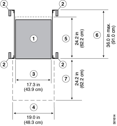
|
1 |
Chassis |
5 |
Depth of the chassis |
|
2 |
Vertical rack-mount posts and rails |
6 |
Maximum extension of the bottom-support rails 36.0 in (91.4 cm) |
|
3 |
Chassis width 17.3 in (43.9 cm) |
7 |
Depth of the front clearance area (equal to the depth of the chassis). |
|
4 |
Width of the front clearance area (equal to the width of the chassis with two rack-mount brackets that are attached to it). 19.0 in (48.3 cm) |
- |
- |
Exhaust fans cool power supplies. System fans cool switches by drawing in air and exhausting air out through various openings in the chassis. Fans also introduce dust and other particles, causing contaminant buildup in the switch and increased internal chassis temperature. Dust and particles can act as insulators and interfere with the mechanical components in the switch. Keep a clean operating environment to reduce the negative effects of dust and other particles.
In addition to keeping your environment free of dust and particles, use these precautions to avoid contamination of your switch:
Do not smoke near the switch.
Do not eat or drink near the switch.
The switch is sensitive to variations in voltage that is supplied by the power sources. Overvoltage, undervoltage, and transients (spikes) can erase data from memory or cause components to fail. To protect against these types of problems, ensure that there is an earth-ground connection for the switch.
Connect the grounding pad on the switch either directly to the earth-ground connection or to a fully bonded and grounded rack.
When the chassis is properly installed in a grounded rack, the switch is grounded because it has a metal-to-metal (no paint, stain, dirt, or anything else on it) contact to the rack. See Note to ensure proper conductivity between rack and switch is maintained.
Alternatively, ground the chassis by using a customer-supplied grounding cable that meets your local and national installation requirements. For U.S. installations, we recommend 6-AWG wire. Connect your grounding cable to the chassis with a grounding lug (provided in the switch accessory kit) and to the facility ground.
Note |
Create an electrical conducting path between the product chassis and the metal surface of the enclosure, or rack in which it is mounted, or to a grounding conductor. Provide electrical continuity by using thread-forming type mounting screws that remove any paint or non-conductive coatings and establish a metal-to-metal contact. Remove any paint or other non-conductive coatings on the surfaces between the mounting hardware and the enclosure or rack. Clean the surfaces and apply an antioxidant before installation. |
High humidity can cause moisture to enter the switch. Moisture can cause corrosion of the internal components and degradation of properties such as electrical resistance, thermal conductivity, physical strength, and size. The switch is rated to withstand from 5% to 90% (nonoperating) and 5% to 90% (operating) relative humidity.
Climate-controlled buildings usually maintain an acceptable level of humidity for the switch equipment. If the switch is located in an unusually humid location, use a dehumidifier to maintain the humidity within an acceptable range.
Electromagnetic interference (EMI) and radio frequency interference (RFI) from the switch can adversely affect other devices, such as radio and television (TV) receivers. Radio frequencies that emanate from the switch can also interfere with cordless and low-power telephones. Conversely, RFI from high-power telephones can cause spurious characters to appear on the switch monitor.
RFI is defined as any EMI with a frequency above 10 kHz. This type of interference can travel from the switch to other devices through the power cable and power source or through the air as transmitted radio waves. The Federal Communications Commission (FCC) publishes specific regulations to limit the amount of EMI and RFI that are emitted by computing equipment. Each switch meets these FCC regulations.
To reduce the possibility of EMI and RFI, use these guidelines:
Cover all open expansion slots with a blank filler plate.
Always use shielded cables with metal connector shells for attaching peripherals to the switch.
When wires are run for any significant distance in an electromagnetic field, interference can occur to the signals on the wires with these implications:
Bad wiring can result in radio interference emanating from the plant wiring.
Strong EMI, especially when it is caused by lightning or radio transmitters, can destroy the signal drivers and receivers in the chassis and even create an electrical hazard by conducting power surges through lines into equipment.
Note |
To predict and prevent strong EMI, consult experts in radio frequency interference (RFI). |
The wiring is unlikely to emit radio interference if you use a twisted-pair cable with a good distribution of grounding conductors. Copper cables should not be longer than maximum distances for the media type.
Note |
If the wires exceed the recommended distances, or if wires pass between buildings, give special consideration to the effect of a lightning strike in your vicinity. The electromagnetic pulse that is caused by lightning or other high-energy phenomena can easily couple enough energy into unshielded conductors to destroy electronic switches. Consult experts in electrical surge suppression and shielding if you have had similar problems in the past. |
The switch includes two power supplies (1-to-1 redundancy with current sharing) in one of these combinations:
Two 650-W AC power supplies
Two 930-W DC power supplies
Two 1200-W HVAC power supplies
Note |
Both power supplies must be of the same type. Do not mix AC and DC power supplies in the same chassis. |
Note |
For 1+1 redundancy, you must use two power sources and connect each power supply to a separate power source. |
The power supplies are rated to output up to 650W AC, 930W DC, or 1200W HVAC, but the switch requires less than these amounts of power from the power supply. To operate the switch, provision enough power from the power source to cover the requirements of both the switch and a power supply. Typically, this switch and a power supply require about 275 W of power input from a power source. But, provision as much as 490 W power input from the power source to cover peak demand.
Note |
Some of the power supply modules have rating capabilities that exceed the switch requirements. When calculating your power requirements, use the switch requirements to determine the amount of power that is required for the power supplies. |
To minimize the possibility of circuit failure, verify that each power-source circuit that is used by the switch is dedicated to the switch.
 Warning |
Statement 1005—Circuit Breaker This product relies on the building’s installation for short-circuit (overcurrent) protection. To reduce risk of electric shock or fire, ensure that the protective device is rated not greater than:
|
Many switch components can be damaged by static electricity. Not exercising the proper electrostatic discharge (ESD) precautions can result in intermittent or complete component failures. To minimize the potential for ESD damage, always use an ESD-preventive anti-static wrist strap (or ankle strap) and ensure that it makes adequate skin contact.
Note |
Check the resistance value of the ESD-preventive strap periodically. The measurement should be 1–10 megohms. Before you perform any of the procedures in this document, attach an ESD-preventive strap to your wrist and connect the leash to the chassis. |
Install these types of racks or cabinets for your switch:
Standard perforated cabinets
Solid-walled cabinets with a roof fan tray (bottom-to-top cooling)
Standard open four-post Telco racks
Work with your cabinet vendors to determine which of their cabinets meet these requirements or see the Cisco Technical Assistance Center (TAC) for recommendations:
Use a standard 19-inch (48.3-cm), four-post Electronic Industries Alliance (EIA) cabinet or rack with mounting rails that conform to English universal hole spacing per section 1 of the ANSI/EIA-310-D-1992 standard.
The depth of a four-post rack must be 24 to 32 inches (61.0 to 81.3 cm) between the front and rear mounting rails (for proper mounting of the bottom-support brackets or other mounting hardware).
You must also have power receptacles that are located within reach of the power cords that are used with the switch.
The switch has been shock- and vibration-tested for operating ranges, handling, and earthquake standards.
The operating temperature of the switch is 32 to 104 degrees Fahrenheit (0 to 40 degrees Celsius) at sea level. For every 300 meters (1000 feet) above sea level, the maximum temperature is reduced by 1 degree Celsius. The non-operating temperature of the switch is -40 to 158 degrees Fahrenheit (-40 to 70 degrees Celsius).
Built-in, automatic sensors in all switches in the Cisco N9000 Series monitor your switch at all times. Each module (supervisor, I/O, and fabric) has temperature sensors with two thresholds: minor and major.
Note |
For any major temperature alarms from the sensors, the switch powers down in 2 minutes. Power on the switch after fixing the temperature issue. |
Minor temperature threshold: If exceeded, a minor alarm occurs and these actions happen for all four sensors:
System messages display.
System sends Call Home alerts (if configured).
System sends SNMP notifications (if configured).
System fan speed will increment.
Major temperature threshold: If exceeded, a major alarm occurs and these actions happen:
If the threshold is exceeded in a switching module, only that module is shut down.
For all sensors:
System messages display.
System sends Call Home alerts (if configured).
System sends SNMP notifications (if configured).
System fan speed will increment.
If the major threshold is exceeded in a switching module, only that module is shut down.
If the major threshold is exceeded in an active supervisor module with HA-standby or standby present, only that supervisor module is shut down and the standby supervisor module takes over.
If you do not have a standby supervisor module in your switch, you have 2 minutes to decrease the temperature. During this interval, the software monitors the temperature every 5 seconds and continuously sends system messages every 10 seconds, as configured.
The regulatory compliance statements and requirements for the Network Equipment Building System (NEBS) certification are listed here.
Warning |
Invisible laser radiation may be emitted from the end of the unterminated fiber cable or connector. Do not view directly with optical instruments. Viewing the laser output with certain optical instruments, for example, eye loupes, magnifiers, and microscopes, within a distance of 100 mm, may pose an eye hazard. |
Warning |
Pluggable optical modules comply with IEC 60825-1 Ed. 3 and 21 CFR 1040.10 and 1040.11 with or without exception for conformance with IEC 60825-1 Ed. 3 as described in Laser Notice No. 56, dated May 8, 2019. |
Note |
This equipment may be ESD sensitive. Always use an ESD ankle or wrist strap before handling equipment. Connect the equipment end of the ESD strap to an unfinished surface of the equipment chassis or to the ESD jack on the equipment if provided. |
Warning |
Statement 7003—Shielded Cable Requirements for Intrabuilding Lightning Surge The intrabuilding port(s) of the equipment or subassembly must use shielded intrabuilding cabling/wiring that is grounded at both ends. The following port(s) are considered intrabuilding ports on this equipment: RJ-45 Management Ethernet port. |
Note |
Statement 7004—Special Accessories Required to Comply with GR-1089 Emission and Immunity Requirements To comply with the emission and immunity requirements of GR-1089, shielded cables are required for the following ports: Copper RJ-45 Ethernet Management port. |
Warning |
Statement 7005—Intrabuilding Lightning Surge and AC Power Fault The intrabuilding port(s) of the equipment or subassembly is suitable for connection to intrabuilding or unexposed wiring or cabling only. The intrabuilding port(s) of the equipment or subassembly MUST NOT be metallically connected to interfaces that connect to the OSP or its wiring for more than 6 meters (approximately 20 feet). These interfaces are designed for use as intrabuilding interfaces only (Type 2, 4, or 4a ports as described in GR-1089) and require isolation from the exposed OSP cabling. The addition of primary protectors is not sufficient protection in order to connect these interfaces metallically to an OSP wiring system. The following ports are considered intrabuilding ports on the equipment: RJ-45 Ethernet Management port. |
Warning |
Connect this equipment to AC mains that are provided with a surge protective device (SPD) at the service equipment that complies with NFPA 70, the National Electrical Code (NEC). |
Note |
This equipment is suitable for installations using the CBN. |
Note |
When you use thread-forming screws to bond equipment to its mounting metalwork, remove any paint and nonconductive coatings and clean the joining surfaces. Apply an antioxidant compound before joining the surfaces between the equipment and mounting metalwork. |
Note |
Statement 7016—Battery Return Conductor Treat the battery return conductor of this equipment as DC-I. |
Note |
The equipment is designed to boot up in less than 30 minutes provided the neighboring devices are fully operational. |
Note |
This equipment is suitable for installation in network telecommunications facilities. |
Note |
This equipment is suitable for installation in locations where the NEC applies. |
 Feedback