Product Overview
The Cisco N9348GC-FXP-ORV3 switch (NC9348GC-FXP-ORV3) is a 1-RU fixed-port, L2/L3 switch, designed for deployment in data centers.
-
48 100/1000-Megabit 1GBASE-T downlink ports
-
4 1/10-/25-Gigabit SFP28 downlink ports
-
2 40-/100-Gigabit QSFP28 uplink ports
-
Fan modules (three) with these airflow choices:
-
Port-side intake airflow with burgundy coloring (NXA-FAN-30CFM-B)
-
Port-side exhaust airflow with blue coloring (NXA-FAN-30CFM-F)

Note
This switch will power down due to a fan-policy trigger if fewer than 2 fans are operational.
Table 1. Fan Speeds for this Switch Port-Side Intake
Fan Speed %
Port-Side Exhaust
Fan Speed %
Typical/Minimum
40%
40%
Maximum
100%
100%
Note
Each fan module has two rotors. The switch can function normally if one rotor inside the any one fan module fails. In case of more than one rotor failure, the switch will issue a warning and power down in 2 minute.
-
-
Power supply modules (two—one for operations and one for redundancy [1+1]) with these choices (a mix of AC and DC power sources is supported but do not mix airflow directions):
-
350-W AC power supply with port-side intake airflow (burgundy coloring) (NXA-PAC-350W-PI2)
-
350-W AC power supply with port-side exhaust airflow (blue coloring) (NXA-PAC-350W-PE2)
-
350-W PHV power supply with port-side intake airflow (burgundy coloring) (NXA-PHV-350W-PI)
-
350-W PHV power supply with port-side exhaust airflow (blue coloring) (NXA-PHV-350W-PE)
-
440-W DC power supply with port-side intake airflow (burgundy coloring) (NXA-PDC-440W-PI)
-
440-W DC power supply with port-side exhaust airflow (blue coloring) (NXA-PDC-440W-PE)
Note
The 350-W AC power supply does not have the standby voltage to be able to carry to a second power supply, to allow it to communicate and poll the device.
-
Deployment Scheme for SFP-10G-T-X Transceivers
There are 4 ports of SFP on the 9348GC-FXP switch in a 2x2 pattern. The SFP-10G-T-X module can be used in all four of these ports.
To determine which transceivers, adapters, and cables this switch supports, see the Cisco Transceiver Modules Compatibility Information document.
Front-Panel Components
This figure shows the hardware features as seen from the port side of the chassis.
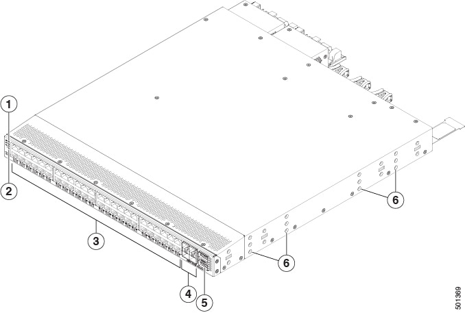
|
1 |
Chassis LEDs (Beacon [BCN], Status [STS], and Environment [ENV]) |
4 |
10-/25-Gigabit SFP28 downlink ports (4) |
|
2 |
LED (P) designated for possible future use |
5 |
40-/100-Gigabit QSFP28 uplink ports (2) |
|
3 |
100-/1000-Megabit 1GBASE-T downlink ports (48) |
6 |
Screw holes (6) for attaching rack mounting brackets |
Rear-Panel Components
This figure shows the hardware features as seen from the power supply side of the chassis.
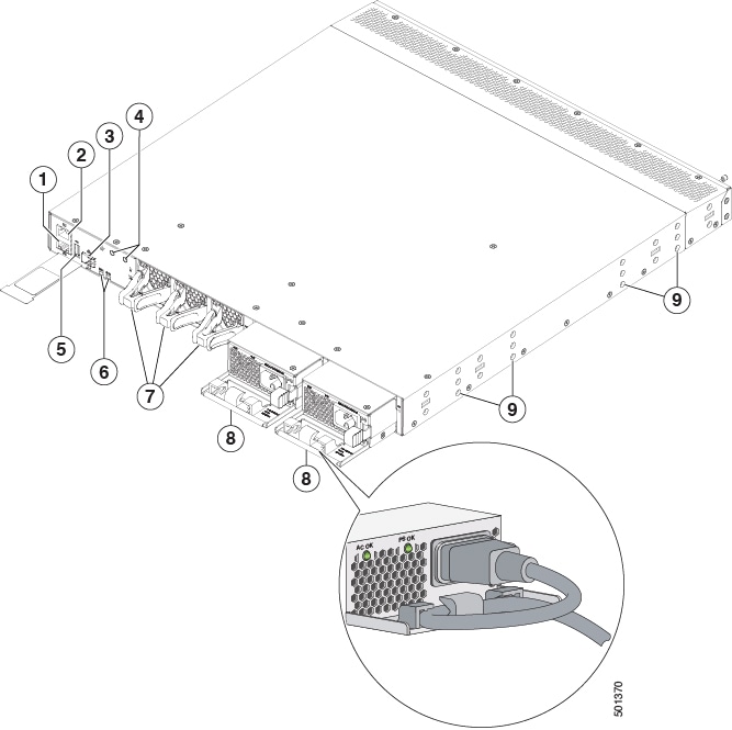
|
1 |
Management port (RJ-45 port) |
6 |
Chassis LEDs (Beacon [BCN] and Status [STS]) |
|
2 |
Console port (RS-232 port) |
7 |
Fan module (3) with fan slot 1 on the left and fan slot 3 on the right |
|
3 |
Management port (SFP port) |
8 |
Power supply (2) one used for operations and one used for redundancy, with power supply slot 1 on the left and slot 2 on the right |
|
4 |
Grounding pad |
9 |
Screw holes (6) for attaching rack mounting brackets |
|
5 |
USB port |
- |
Note |
USB support is limited to USB 2.0 devices that use less than 2.5 W (less than 0.5 A inclusive of surge current). Devices, such as external hard drives, that instantaneously draw more than 0.5 A are not supported. |
Depending on whether you plan to position the ports in a hot or cold aisle, you can order the fan and power supply modules with port-side intake or port-side exhaust airflow. To determine the airflow direction of the modules installed in your switch, see this table.
| Replaceable Modules | Port-Side Intake Airflow Coloring | Port-Side Exhaust Airflow Coloring |
|---|---|---|
| Fans | Burgundy | Blue |
| AC power supplies | Burgundy | Blue |
The fan and power supply modules are field replaceable. You can replace one fan module or one power supply module during operations, so long as the other modules are installed and operating. If you have only one power supply installed, you can install the replacement power supply in the open slot before removing the original power supply.
All of the fan and power supply modules must have the same direction of airflow. Otherwise, the switch can overheat and shut down. If you are installing a dual-direction power supply, that module automatically uses the same airflow direction as the other modules in the switch.
 Caution |
If the switch has port-side intake airflow (burgundy coloring for fan modules), you must locate the ports in the cold aisle. If the switch has port-side exhaust airflow (blue coloring for fan modules), you must locate the ports in the hot aisle. If you locate the air intake in a hot aisle, the switch can overheat and shut down. |
 Feedback