
Safety

Before you install, operate, or service the switch, see the Regulatory, Compliance, and Safety Information for the Cisco N9000 Series content for important safety information


Warning


IMPORTANT SAFETY INSTRUCTIONS

Before you work on any equipment, be aware of the hazards involved with electrical circuitry and be familiar with standard practices for preventing accidents. Read the installation instructions before using, installing, or connecting the system to the power source. Use the statement number at the beginning of each warning statement to locate its translation in the translated safety warnings for this device.

SAVE THESE INSTRUCTIONS


Note


You are strongly advised to read the safety instruction before using the product.

https://www.cisco.com/web/JP/techdoc/pldoc/pldoc.html

When installing the product, use the provided or designated connection cables/power cables/AC adapters.

〈製品使用における安全上注意〉

www.cisco.com/web/JP/techdoc/index.html

続ケーブル、電源コードセットACアダプタバッテリなどの部品、必添付品または

指定品をご使用ください。添付品指定品以外をご使用になると故障動作不良、火災

原因となりますまた、電源コードセットは弊社指定する製品以外機器には使用

できないためご注意ください。

Warning


To reduce risk of electric shock or personal injury, disconnect DC power before removing or replacing components or performing upgrades.


Caution


To prevent loss of input power, ensure the total maximum loads on the circuits supplying power to the switch are within the current ratings for the wiring and breakers.


Note


For AC input application, please refer to the statement below.


Warning


Statement 1005—Circuit Breaker

This product relies on the building’s installation for short-circuit (overcurrent) protection. To reduce risk of electric shock or fire, ensure that the protective device is rated not greater than: 20A (North America), 16A (Europe), and 13A (UK).


Warning


To prevent bodily injury when mounting or servicing this unit in a rack, you must take special precautions to ensure that the system remains stable. The following guidelines are provided to ensure your safety:

  • This unit should be mounted at the bottom of the rack if it is the only unit in the rack.

  • When mounting this unit in a partially filled rack, load the rack from the bottom to the top with the heaviest component at the bottom of the rack.

  • If the rack is provided with stabilizing devices, install the stabilizers before mounting or servicing the unit in the rack.


Warning


This unit is intended for installation in restricted access areas. Only skilled, instructed, or qualified personnel can access a restricted access area.


Warning


To reduce the risk of electric shock and fire, a readily accessible disconnect device must be incorporated in the fixed wiring.


Warning


This equipment must be grounded. To reduce the risk of electric shock, never defeat the ground conductor or operate the equipment in the absence of a suitably installed ground conductor. Contact the appropriate electrical inspection authority or an electrician if you are uncertain that suitable grounding is available.


Warning


This unit might have more than one power supply connection. To reduce risk of electric shock, remove all connections to de-energize the unit.


Warning


To reduce the risk of electric shock, connect the unit only to a DC power source that complies with the SELV requirements in the IEC 60950-based safety standards or the ES1 requirements in the IEC 62368-based safety standards.


Warning


To prevent personal injury or damage to the chassis, never attempt to lift or tilt the chassis using the handles on modules, such as power supplies, fans, or cards. These types of handles are not designed to support the weight of the unit.


Warning


To reduce risk of electric shock, when installing or replacing the unit, the ground connection must always be made first and disconnected last.

If your unit has modules, secure them with the provided screws.


Warning


Invisible laser radiation is present. Do not expose to users of telescopic optics. This applies to Class 1/1M laser products.


Warning


To reduce risk of electric shock or fire, installation of the equipment must comply with local and national electrical codes.


Note


An instructed person is someone who has been instructed and trained by a skilled person and takes the necessary precautions when working with equipment.

A skilled person or qualified personnel is someone who has training or experience in the equipment technology and understands potential hazards when working with equipment.


Warning


Only an instructed person or skilled person should be allowed to install, replace, or service this equipment. See statement 1089 for the definition of an instructed person or skilled person.


Install options with rack-mount kits

The rack-mount kit enables you to install the switch into racks of varying depths. Position the switch with easy access to either the port connections or the fan and power supply modules.

Install the switch using these rack-mount options.

  • Rack-mount kit (NXK-ACC-KIT-1RU) which you can order from Cisco. This option offers you easy installation, greater stability, increased weight capacity, added accessibility, and improved removability with front and rear removal.

    • When installing the NXK-ACC-KIT-1RU rack-mount kit, the distance between the outside face of the front mounting rail and the outside face of the back mounting rail should be 25.37 to 33 inches (64.43 to 83.82 cm) to allow for rear-bracket installation.

  • Rack-mount kit (N3K-C3064-ACC-KIT) which you can order from Cisco.

    • When installing the N3K-C3064-ACC-KIT rack-mount kit, the distance between the outside face of the front mounting rail and the outside face of the back mounting rail should be 22 to 30 inches (55.88 to 76.2 cm) to allow for rear-bracket installation.

The rack or cabinet that you use must meet the requirements listed the in General Requirements for Cabinets and Racks section.


Note


You are responsible for verifying that your rack and rack-mount hardware comply with the guidelines that are described in this document.


Airflow considerations

The switch comes with fan and power supply modules that have either port-side intake or port-side exhaust airflow for cooling the switch.

If you are positioning the port end of the switch in a cold aisle, verify that the switch has port-side intake fan modules with burgundy coloring. If you are positioning the fan and power supply modules in a cold aisle, verify that the switch has port-side exhaust fan modules with blue colorings. All fan modules must have the same direction of airflow.

Guidelines to install the switch

When installing the switch, follow these guidelines.

  • Ensure that there is adequate clearance space around the switch to allow for servicing the switch and for adequate airflow.

  • Ensure that you are positioning the switch in a rack so that it takes in cold air from the cold aisle and exhausts air to the hot aisle. If there is blue coloring on the fan modules, the switch is configured for port-side exhaust airflow and you must position the module side of the switch in a cold aisle. If there is burgundy coloring on the fan modules, the switch is configured for port-side intake airflow and you must position the port side of the switch in a cold aisle.

  • Ensure that the chassis can be adequately grounded. If the switch is not mounted in a grounded rack, we recommend connecting the system ground on the chassis directly to an earth ground.

  • Ensure that the site power meets the power requirements for the switch. If available, use an uninterruptible power supply (UPS) to protect against power failures.


    Note


    Avoid UPS types that use ferroresonant technology. These UPS types can become unstable with the switch, which can have substantial current draw fluctuations because of fluctuating data traffic patterns.


  • • Ensure that circuits are sized according to local and national codes. Typically, this often requires one or both of these:

    • AC power supplies typically require at least a 15-A or 20-A AC circuit, 100 to 240 VAC, and a frequency of 50 to 60 Hz.


      Note


      To prevent loss of input power, ensure the total maximum loads on the circuits supplying power to the switch are within the current ratings for the wiring and breakers.


Unpack and inspect the switch

Before you install a new chassis, unpack and inspect it to be sure that you have all the items that you ordered. Verify that the switch was not damaged during shipment. If anything is damaged or missing, contact your customer representative immediately.


Note


When you handle the chassis or its components, follow ESD protocol at all times to prevent ESD damage. This protocol includes but is not limited to wearing an ESD wrist strap that you connect to the earth ground.


Tip


Do not discard the shipping container when you unpack the switch. Flatten the shipping cartons and store them. If you need to move or ship the system in the future, you will need this container.


Before you begin

Before you unpack the switch and before you handle any switch components, be sure that you are wearing a grounded electrostatic discharge (ESD) strap. To ground the strap, attach it directly to an earth ground or to a grounded rack or grounded chassis (there must be a metal-to-metal connection to the earth ground).

Procedure


Step 1

Compare the shipment to the equipment list that is provided by your customer service representative. Verify that you have received all of the ordered items.

The shipment should include:

  • Switch chassis

  • Accessory kit

  • Rack-mount kit

Step 2

Check the contents of the shipping box for damage.

Step 3

Check for damage and report any discrepancies or damage to your customer service representative. Have the following information ready.

  • Invoice number of the shipper (see packing slip).

  • Model and serial number of the missing or damaged unit.

  • Description of the problem and how it affects the installation.

  • Effect of damage on the installation.

Step 4

Check to be sure that each of the power supply and the fan tray modules have the expected direction of airflow.

  • Port-side intake airflow modules

    • Burgundy (fan modules and AC power supplies)

  • Port-side exhaust airflow modules

    • Blue (fan modules and AC power supplies)

Note


All power supplies and fan modules must have the same direction of airflow.


Tools and equipment

Obtain these necessary tools and equipment for installing the chassis:

  • Number 1 and number 2 Phillips screwdrivers with torque capability to rack-mount the chassis.

  • 3/16-inch flat-blade screwdriver.

  • Tape measure and level.

  • ESD wrist strap or other grounding device.

  • Antistatic mat or antistatic foam.

  • Crimping tool for lug.

  • Wire-stripping tool.

  • M4 screws to fix brackets (16).

  • M4 screws to fix a ground lug (2).

Install the switch into a two-post rack

To install the switch, you must attach mounting brackets to the switch and secure the switch to the rack. Installation in racks other than 19-inch racks requires a bracket kit not included with the switch.

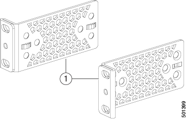
The following figure shows the standard 19-inch mounting brackets.

1

Standard mounting bracket for a 19-inch, two-post rack

Procedure


Step 1

Install the brackets to the switch.

  1. Determine which end of the chassis is to be located in the cold aisle as follows:

    • If the switch has port-side intake modules (fan modules with burgundy coloring), position the switch so that its ports will be in the cold aisle.

    • If the switch has port-side exhaust modules (fan modules with blue coloring), position the switch so that its fan and power supply modules will be in the cold aisle.

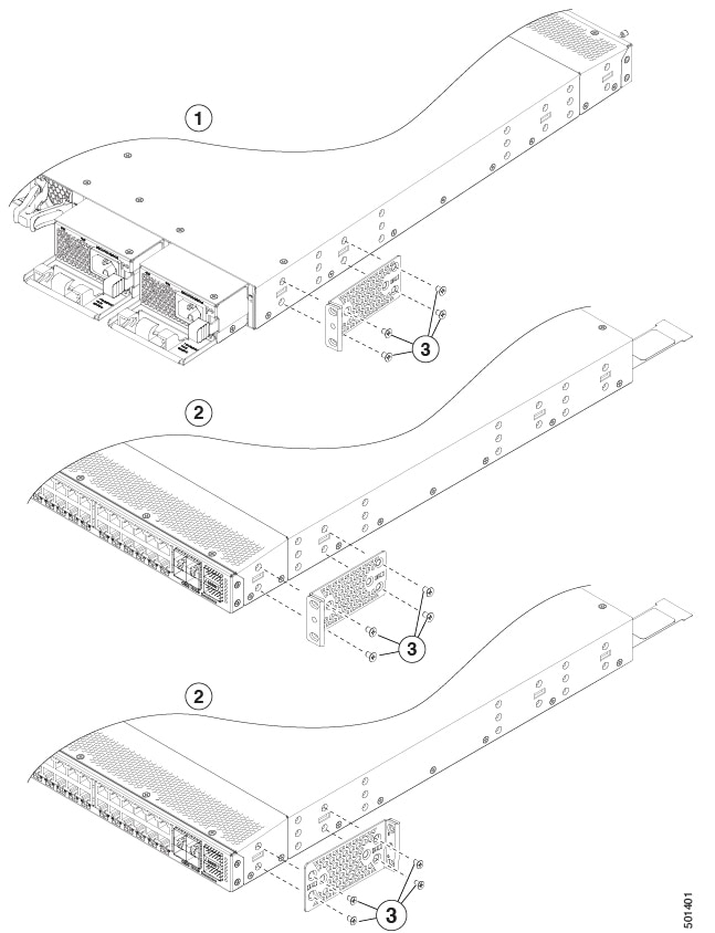
  2. Position the bracket so that four of its screw holes are aligned to the screw holes on the side of the chassis as shown in the following figure.


    Position the bracket

    1

    Rear-mounting position

    3

    Number-8 Phillips flat-head screws (4 each bracket)

    2

    Front-mounting position

    -

  3. Secure the bracket to the chassis using four Number-8 Phillips flat-head screws and tighten each screw to 12 in-lb (1.36 N·m) of torque.

  4. Repeat previous step for the other front rack-mount bracket on the other side of the switch and be sure to position that bracket the same distance from the front of the switch.

Step 2

Install the chassis into the rack.

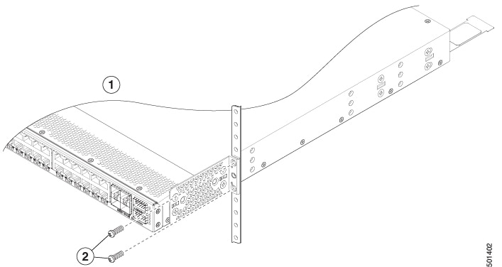
  1. Use two M4 screws to attach the brackets to the rack.


Install the chassis into the rack

1

Front-mounting position

2

M4 screws (2 each side)


Install the switch on an ORV3 rack

Open Rack Version 3 (ORV3) is a specification to build base frames for large scale deployment of racks. ORV3 adheres to the open hardware standards and is compatible with a wide range of IT equipment and facilitates interoperability with other Open Compute Project (OCP)-compliant hardware.

The N9K-9332D-GX2B-ORV3 switch is bundled or pre-installed on a tray to faciliate rack mounting the switch on ORV3 racks.

The tray with the preinstalled switch can be rack mounted on to the ORV3 rack.

Features of the switch preinstalled on the tray

To ensure that the preinstalled switch is compatible with the ORV3 rack,

  • Fans and power supply modules are hot swappable.

  • The serial number barcode and MAC address can be scanned.

  • Option to access RJ-45 Ethernet ports from the front panel of the switch.

  • A converter board to convert +48V busbar on the ORV3 rack to -48V.

    Cisco switches require -48V power source.

  • Inrush current prevention inbuilt into the power supply modules and converter boards to limit electric current spikes.

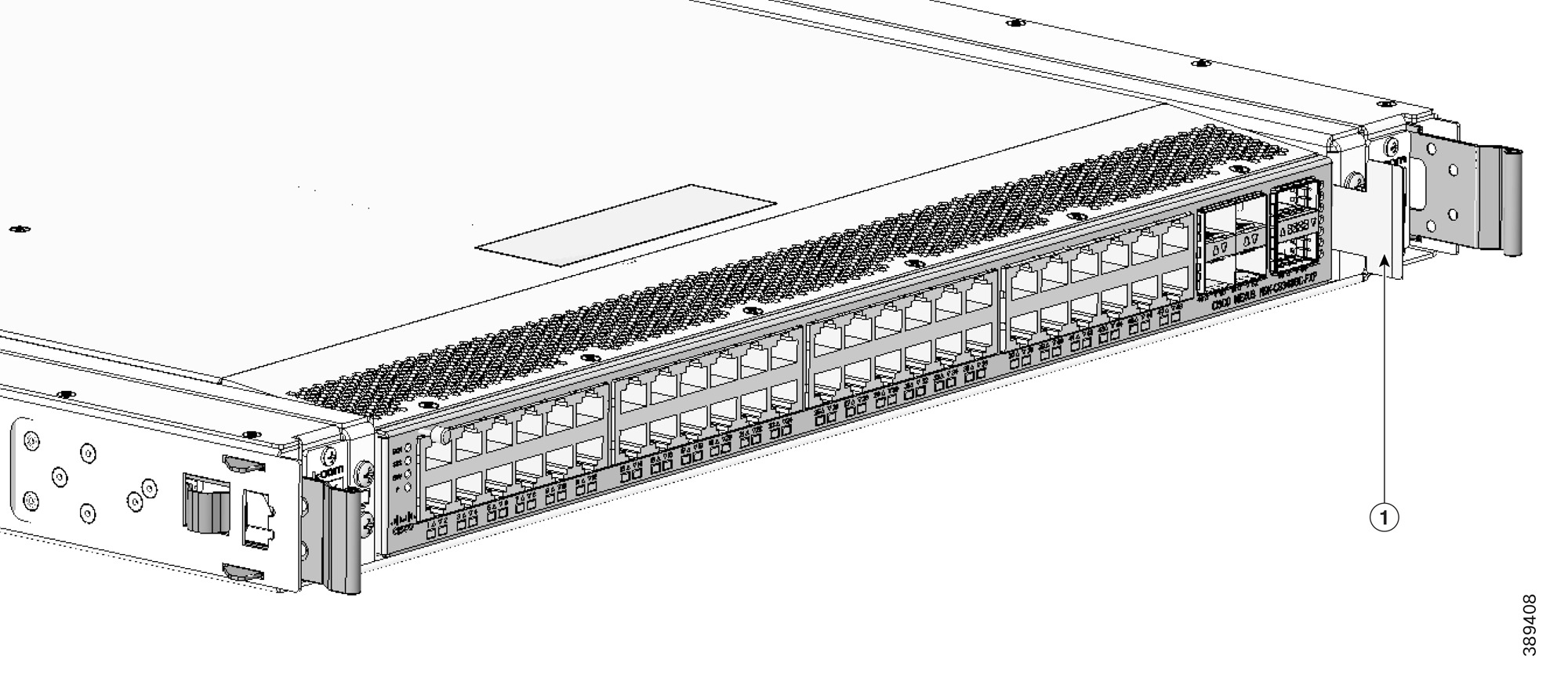
Pictorial representation of the preinstalled switch

This illustration displays the pullout for scanning the serial number.

Figure 1. Pullout for scanning the serial number

1

Pullout for scanning the switch serial number

-

-

This illustration displays the front view of the switch preinstalled on an ORV3 tray. Four captive screws secure the switch to the tray.

Figure 2. Front view of the switch preinstalled on an ORV3 tray

Front view of the switch preinstalled on an ORV3 tray

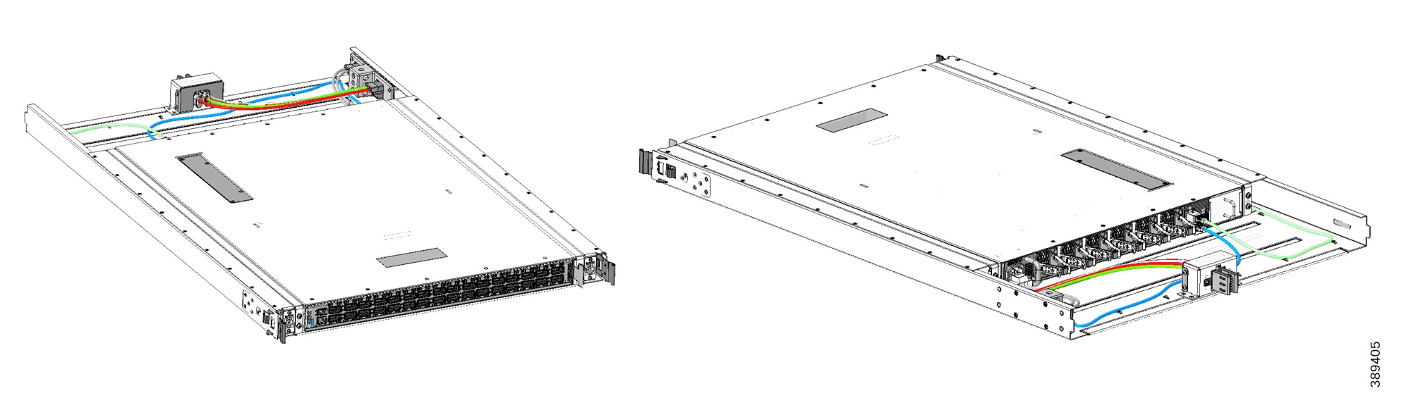
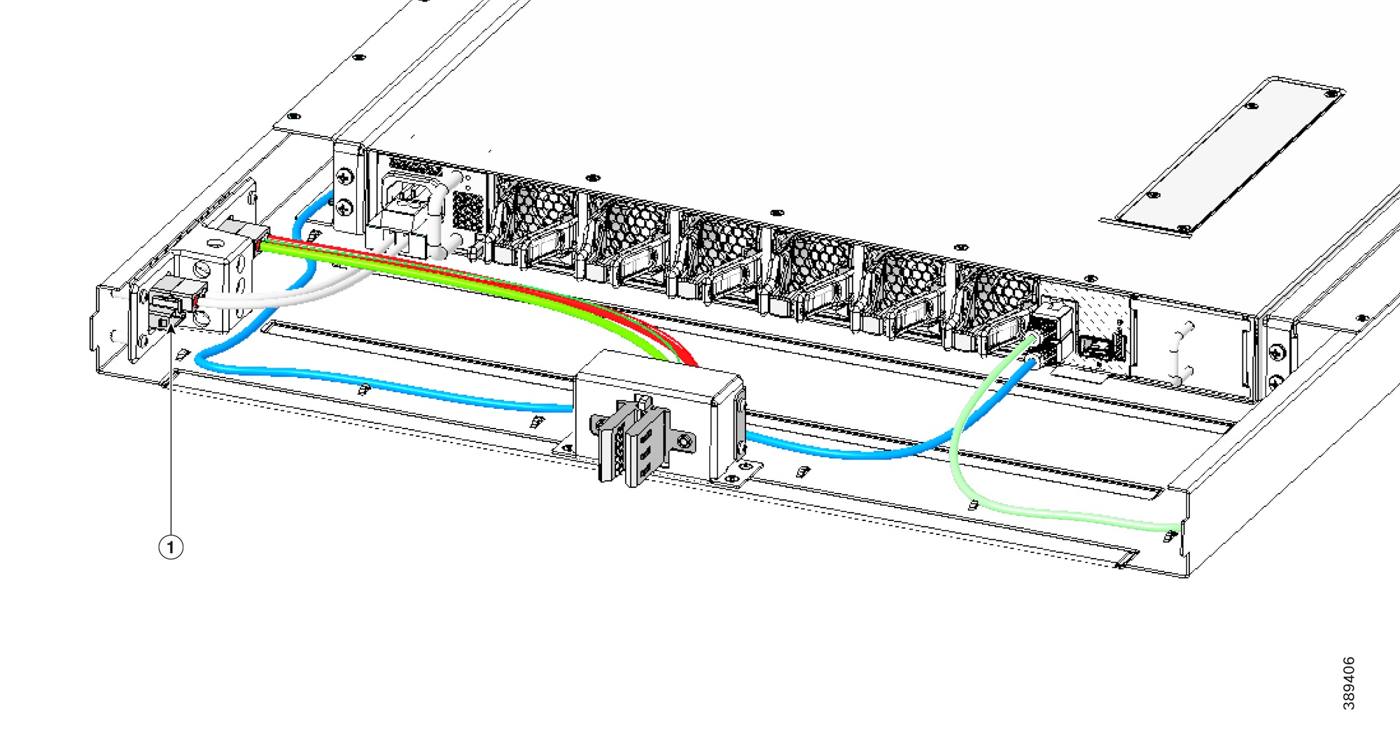
This illustration displays the rear view of the switch preinstalled on a tray.

Figure 3. Rear view of the preinstalled switch

Rear view of the preinstalled switch

1

RJ-45 connector

-

-

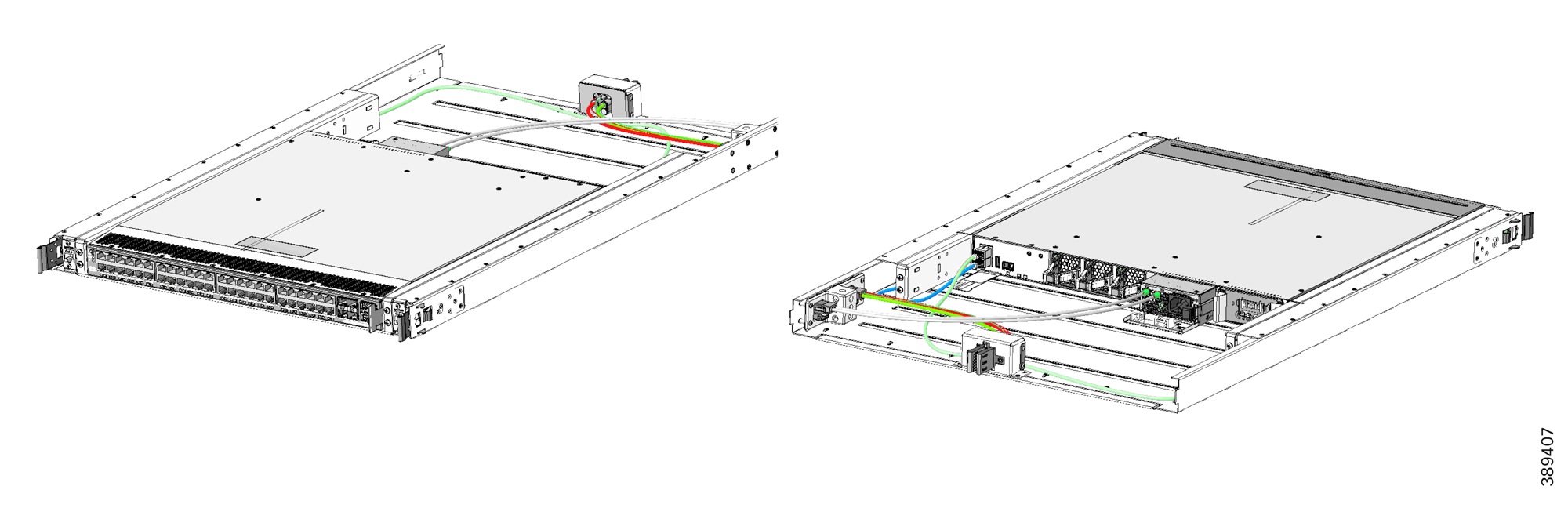
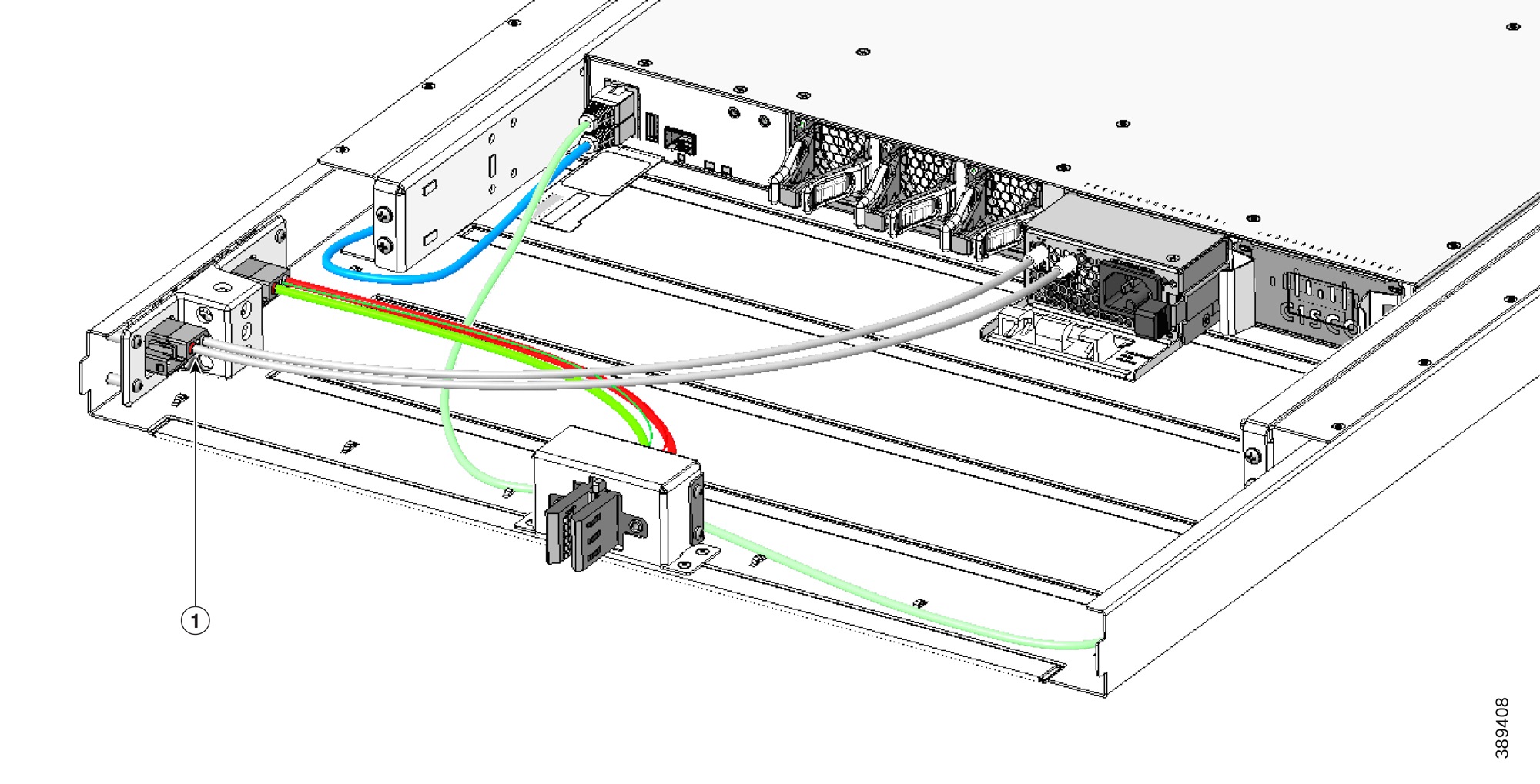
You must unplug the left power supply cable and push up the right power supply cables to remove the left power supply unit.

This illustration displays the placement of RJ-45 Ethernet ports and RJ-45 cables that connect the ports.

Figure 4. Placement of the RJ-45 Ethernet ports and cables

1

RJ-45 cables

Install the airflow sleeve (N9K-AIRFLOW-SLV)

Install the airflow sleeve (N9K-AIRFLOW-SLV) to allow proper airflow, so that the switch is properly cooled. This airflow sleeve is only compatible with rack mount kit (N3K-C3064-ACC-KIT).

Table 1. Minimum and maximum rack rail depth

Chassis

Minimum rack rail depth

Maximum rack rail depth

N9K-C9348GC-FXP

672.49 mm

764.29 mm


Note


You supply the screws to mount the airflow sleeve.


Before you begin

  • Verify that your shipment is complete.

  • Install your rack in a secure location.

Procedure


Insert the airflow sleeve into the rack and attach it.

  1. Holding the airflow sleeve (N9K-AIRFLOW-SLV) with both hands, position it in front of the fan side of the chassis.

  2. Holding the airflow sleeve level, insert screws (12-24 or 10-32, depending on the rack type) in each of the two front rack-mount flanges (using a total of two screws) and into the cage nuts or threaded holes in the vertical rack-mounting rails (see the figure).


    tighten screws on airflow sleeves

  3. Tighten the 10-32 screws to 20 in-lb (2.26 N·m) or tighten the 12-24 screws to 30 in-lb (3.39 N·m) of torque.


Ground the chassis

The switch chassis is automatically grounded when you properly install the switch in a grounded rack with metal-to-metal connections between the switch and rack.


Note


Provide an electrical conducting path between the product chassis and the metal surface of the enclosure or rack in which it is mounted or to a grounding conductor. To ensure electrical continuity, use thread-forming type mounting screws that remove any paint or non-conductive coatings and establish a metal-to-metal contact. Remove any paint or other non-conductive coatings on the surfaces between the mounting hardware and the enclosure or rack. Clean the surfaces and apply an antioxidant before installation.


If using AC or HVDC power supplies, the power cord for the AC power supplies provides grounding for the chassis. For supplemental grounding or bonding, attach a customer-supplied grounding cable to the chassis ground pad.

Ground the chassis. If you are using a 2-post rack, attach a customer-supplied grounding cable. Attach the cable to the chassis grounding pad and the facility ground. If you are using a 4-post rack, ensure that your chassis is grounded through the rack mount system or the power cable (AC or HVDC).


Warning


This equipment must be grounded. To reduce the risk of electric shock, never defeat the ground conductor or operate the equipment in the absence of a suitably installed ground conductor. Contact the appropriate electrical inspection authority or an electrician if you are uncertain that suitable grounding is available.


Warning


To reduce risk of electric shock, when installing or replacing the unit, the ground connection must always be made first and disconnected last.

If your unit has modules, secure them with the provided screws.


Before you begin

Before you can ground the chassis, verify the earth ground contact has a solid connection to the data center building.

Procedure


Step 1

Use a wire-stripping tool to remove approximately 0.75 inch (19 mm) of the covering from the end of the grounding wire. We recommend 6-AWG wire for the U.S. installations.

Step 2

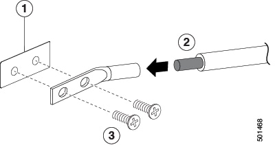
Insert the stripped end of the grounding wire into the open end of the grounding lug. Use a crimping tool to crimp the lug to the wire. See the figure. Verify that the ground wire is securely attached to the grounding lug by attempting to pull the wire out of the crimped lug (tug test).

1 Chassis grounding pad 3 2 M4 screws are used to secure the grounding lug to the chassis
2 Grounding cable, with 0.75 in. (19 mm) of insulation that is stripped from one end, which is inserted into the grounding lug and crimped in place

Step 3

Secure the grounding lug to the chassis grounding pad with two M4 screws, see figure 1. Tighten the screws to 11 to 15 in-lb (1.24 to 1.69 N m) of torque.

Step 4

Prepare the other end of the grounding wire and connect it to the facility ground.


Start the switch

Start the switch by connecting it to its dedicated power source. If you need n+n redundancy, connect each power supply in a switch to a different power source.


Note


This equipment is designed to boot up in less than 30 minutes, dependent on its neighboring devices being fully up and running.


Before you begin

  • The switch must be installed and secured to a rack or cabinet.

  • The switch must be adequately grounded.

  • The rack must be close enough to the dedicated power source so that you can connect the switch to the power source by using the designated power cables.

  • You have the designated power cables for the power supplies that you are connecting to the dedicated power sources.


    Note


    Depending on the outlet receptacle on your AC power distribution unit, you might need an optional jumper power cord to connect the switch to your outlet receptacle.


  • The switch is not connected to the network (this includes any management or interface connections).

  • The fan and power supply modules are fully secured in their chassis slots.

Procedure


Step 1

For the AC power supply, do this:

  1. Using the recommended AC power cable for your country or region, connect one end to the AC power supply.

  2. Connect the other end of the power cable to the AC power source.

Step 2

For any HVAC/HVDC power supply, connect it to a power source.

  • Using the recommended high voltage power cable for your country or region, connect the Anderson Power Saf-D-Grid connector on the power cable to the power receptacle on the power supply. Make sure that the connector clicks when fully pushed into the receptacle.

  • Connect the other end of the power cable to a power source.

    • Verify that the power is turned off at a circuit breaker for the power source terminals.

    • Remove the nuts from each of the terminal posts for the power supply.

    • Place the power cable negative-wire terminal ring on the negative terminal for the power source and secure them with a terminal nut.

    • Place the power cable positive-wire terminal ring on the positive terminal for the power source and secure them with a terminal nut.

    • Place the power cable ground-wire terminal ring on the ground terminal for the power source and secure them with a terminal nut.

    • If there is a safety cover for the power source terminals, place and secure it over the terminals to avoid an electrical shock hazard.

    • Turn on the power at the power source circuit breaker.

Step 3

For any DC power supply

  • Turn off the circuit breaker for the power source to avoid an electrical shock hazard.

  • Verify that the power cable wires from the power source are connected to a connector block.

  • Insert the connector block into the receptacle on the power supply. Make sure that the connector block clicks when fully inserted in the receptacle and does not pull out.

  • If there is a safety cover for the terminals, place and secure it over the terminals to avoid an electrical shock hazard.

  • Turn on the power at the circuit breaker for the DC power source.

Step 4

Verify that the power supply LED is on and green.

Step 5

Listen for the fans; they should begin operating when the power supply is powered.

Step 6

After the switch boots, verify that the following LEDs are lit.

  • On the fan modules, the Status (STA or STS) LED is green.

    If a fan module Status LED is not green, try reinstalling the fan module.

  • After initialization, the switch chassis Status (labeled as STA or STS) LED is green.

Step 7

Verify that the system software has booted and the switch has initialized without error messages.

A setup utility automatically launches the first time that you access the switch and guides you through the basic configuration. For instructions on how to configure the switch and check module connectivity, see the appropriate Cisco N9000 Series Configuration Guides.